

Omron H3DE DATASHEET
Solid-state Timer
H3DE
DIN Track Mounted, Standard 22.5-mm Width Timer Range
• A wide AC/DC power supply range (24 to 230 VAC/DC) reduces the number of timer models kept in stock. (except for H3DE-H)
• 12-VDC model available for a specific application. (H3DE-M2)
• Nameplate provided for easy timer identification and management.
• Terminal clamp left open when delivered.
• Finger protection terminal block to meet VDE0106/P100.
• Enables easy sequence checks through instantaneous outputs for a zero set value at any time range.
• Incorporates environment-friendly, cadmium-free contacts. (except for H3DE-H)
• High immunity to inverter noise.
• Approved by UL and CSA.
• Conforms to EN61812-1 and IEC60664-1 4 kV/2 for Low Voltage, and EMC Directives.
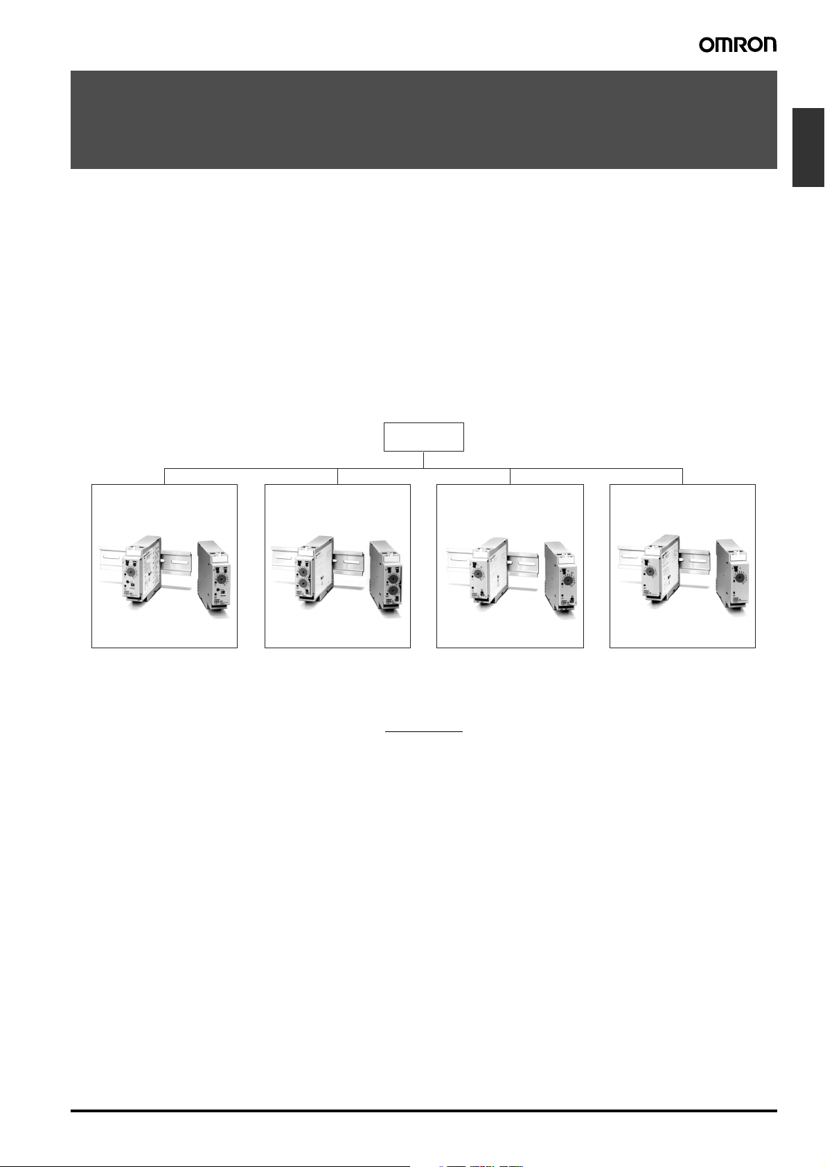
■ Broad Line-up of H3DE Series
H3DE
H3DE-M/S H3DE-F H3DE-G H3DE-H
Timers
Standard Timer Twin Timer
H3DE-M
H3DE-S
Solid-state Timer
H3DE-M/-S...................................................................................................................................... B-53
H3DE-F ........................................................................................................................................... B-63
H3DE-G .......................................................................................................................................... B-69
H3DE-H........................................................................................................................................... B-75
Common to ALL Timers
Accessories..................................................................................................................................... B-81
Precautions ..................................................................................................................................... B-82
H3DE-F
Star-delta Timer
H3DE-G
Contents
Power OFF-delay Timer
H3DE-H
Solid-state Timer H3DE B-51

52 Solid-state Timer H3DE
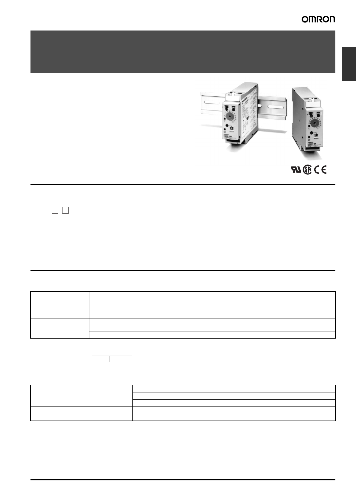
Solid-state Multi-functional Timer
H3DE-M/-S
• Eight operating modes (H3DE-M) and four operating modes
(H3DE-S) cover a wide range of applications.
• Programmable contact enables the building of a self-holding relay circuit (-@2 models).
• A wide time setting range of 0.10 s to 120 h.
Model Number Structure
■ Model Number Legend
H3DE -
1 2
1. M: Multi-function type
S: Standard type
2. 2: DPDT
1: SPDT
Timers
Ordering Information
■ List of Models
Supply voltage Control output Model
Multi-function type Standard type
12 VDC Contact output: DPDT (time-limit output SPDT and switchable
SPDT (time-limit ←→ instantaneous))
24 to 230 VAC/DC Contact output: DPDT (time-limit output SPDT and switchable
SPDT (time-limit ←→ instantaneous))
Contact output: SPDT (time-limit output SPDT) H3DE-M1 H3DE-S1
Note: Specify both the model number and supply voltage when ordering H3DE-M2.
Example: H3DE-M2 24 to 230 VAC/DC
Supply voltage
■ Accessories (Order Separately)
Mounting Track 50 cm (l) x 7.3 mm (t) PFP-50N
1 m (l) x 7.3 mm (t) PFP-100N
1 m (l) x 16 mm (t) PFP-100N2
End Plate PFP-M
Spacer PFP-S
H3DE-M2
(see note)
H3DE-M2
(see note)
---
H3DE-S2
Solid-state Multi-functional Timer H3DE-M/-S B-53
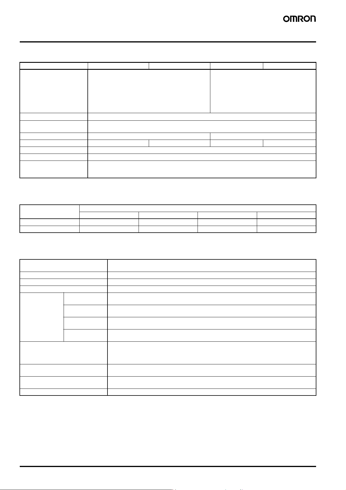
Specifications
■ General
Item H3DE-M2 H3DE-M1 H3DE-S2 H3DE-S1
Operating mode A: ON-delay (Signal or Power)
Terminal block
Terminal screw tightening
torque
Input type Voltage input ---
Output type Relay: DPDT Relay: SPDT Relay: DPDT Relay: SPDT
Mounting method DIN track mounting (see note)
Attachment Nameplate
Approved standards UL508, CSA 22.2 No.14
Note: Can be mounted to 35-mm DIN track with a plate thickness of 1 to 2.5 mm.
B: Flicker OFF start (Signal or Power)
B2: Flicker ON start (Signal or Power)
C: Signal ON/OFF-delay
D: Signal OFF-delay
E: Interval (Signal or Power)
G: Signal ON/OFF-delay
J: One-shot (Signal or Power)
Clamps two 2.5 mm
0.98 N·m max. {approx. 10 kgf·cm max.}
Conforms to EN61812-1, IEC60664-1 4 kV/2, VDE0106/P100
Output category according to IEC60947-5-1 (AC-13; 250 V 5A/AC-15; 250 V 3 A/DC-13; 30 V 0.1 A)
2
max. bar terminals without sleeves.
■ Time Ranges
A: ON-delay
B2: Flicker ON start
E: Interval
J: One-shot
Time scale display Time unit display
sec min hrs 10 h
x 0.1 0.1 to 1.2 s 0.1 to 1.2 min 0.1 to 1.2 h 1 to 12 h
x 1 1 to 12 s 1 to 12 min 1 to 12 h 10 to 120 h
Note: When the main dial is set to “0” for all settings, the output will operate instantaneously.
■ Ratings
Rated supply voltage
(see notes 1 and 2)
Operating voltage range 85% to 110% of rated supply voltage
Power reset Minimum power-off time: 0.1 s
Reset voltage 2.4 VAC/DC max.
Power consump-
tion (see note 3)
Voltage input Max. permissible capacitance between input lines (terminals B1 and A2): 2000 pF
Control output Contact output: 5 A at 250 VAC with resistive load (cosφ = 1)
Ambient temperature Operating: −10°C to 55°C (with no icing)
Ambient humidity Operating: 35% to 85%
Note: 1. DC ripple rate: 20% max.
2. Since an inrush current of 0.25 A will occur when using the power supply voltage at 24 VDC, pay careful attention when turning on or off
the power supply to the Timer with a solid-state output such as a sensor.
3. The power consumption is for mode A after the Timer counts the time-up time and for the AC input at 50 Hz. The power consumption of
the H3DE-M@ includes the input circuit with the B1 and A1 terminals short-circuited.
H3DE-M1 AC: approx. 4.3 VA (2.2 W) at 230 VAC
H3DE-M2 AC: approx. 4.8 VA (2.4 W) at 230 VAC
H3DE-S1 AC: approx. 2.7 VA (1.6 W) at 230 VAC
H3DE-S2 AC: approx. 3.2 VA (1.9 W) at 230 VAC
24 to 230 VAC/DC (50/60 Hz)
12 VDC (H3DE-M2 model only)
DC: approx. 0.7 W at 24 VDC
DC: approx. 1.0 W at 24 VDC
DC: approx. 0.7 W at 24 VDC
DC: approx. 1.0 W at 24 VDC
Load connectable in parallel with inputs (terminals B1 and A2)
H-level: 20.4 to 253 VAC/DC
L-level: 0 to 2.4 VAC/DC
5 A at 30 VDC with resistive load (cosφ = 1)
Storage: −25°C to 65°C (with no icing)
B-54 Solid-state Multi-functional Timer H3DE-M/-S
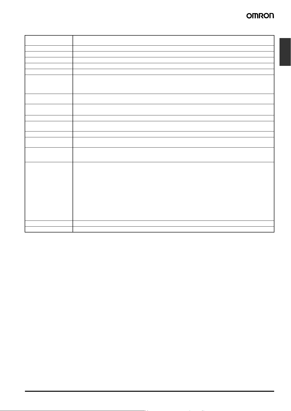
■ Characteristics
Accuracy of operating
time
Setting error ±10% ±50 ms max. of FS (see note 1)
Signal input time 50 ms min. (see note 1)
Influence of voltage ±0.5% max. of FS (±0.5% ±10 ms max. at 1.2-s range)
Influence of temperature ±2% max. of FS (±2%±10 ms max. at 1.2-s range)
Insulation resistance 100 MΩ min. at 500 VDC
Dielectric strength Between current-carrying metal parts and exposed non-current-carrying metal parts: 2,000 VAC for 1 min.
Vibration resistance Malfunction: 0.5-mm single amplitude at 10 to 55 Hz
Shock resistance
Contact material AGNi+gold plating (Use the G6RN-1 at 12 VDC.)
Impulse withstand volt-
age
Noise immunity Square-wave noise generated by noise simulator (pulse width: 100 ns/1 µs, 1-ns rise) ±1.5 kV
Static immunity Malfunction: 4 kV
Life expectancy Mechanical: 10 million operations min. (under no load at 1,800 operations/h)
EMC (EMI) EN61812-1
Degree of protection IP30 (Terminal block: IP20)
Weight 120 g
Note: 1. With the H3DE-M@, if the voltage exceeds 26.4 VAC/DC, the following hold at signal OFF for C, D, and G modes:
Accuracy of operating time: ±1% ±50 ms max. at 1.2-s range
Setting error: ±10% +100/−50 ms max.
Signal input time: 100 ms min.
2. For reference: A maximum current of 0.15 A can be switched at 125 VDC (cosφ=1).
A maximum current of 0.1 A can be switched if L/R is 7 ms.
In both cases, a life of 100,000 operations can be expected.
The minimum applicable load is 10 mA at 5 VDC (failure level: P).
±1% max. of FS (±1% ±10 ms max. at 1.2-s range) (see note 1)
Between control output terminals and operating circuit: 2,000 VAC for 1 min.
Between contacts of different polarities: 2,000 VAC for 1 min.
Between contacts not located next to each other: 1,000 VAC for 1 min.
Destruction: 0.75-mm single amplitude at 10 to 55 Hz
Malfunction: 100 m/s
Destruction: 1,000 m/s
3 kV (between power terminals)
4.5 kV (between current-carrying metal parts and exposed non-current-carrying metal parts)
Destruction: 8 kV
Electrical: 100,000 operations min. (5 A at 250 VAC, resistive load at 360 operations/h)
Emission Enclosure: EN55011 Group 1 class B
Emission AC Mains: EN55011 Group 1 class B
Harmonic Current: EN61000-3-2
Voltage Fluctuation and Flickering: EN61000-3-3
(EMS) EN61812-1
Immunity ESD: EN61000-4-2: 6 kV contact discharge (level 3)
Immunity RF-interference from AM Radio Waves: EN61000-4-3: 10 V/m (80 MHz to 1 GHz) (level 3)
Immunity Burst: EN61000-4-4: 2 kV power port and output port (level 3)
Immunity Surge: EN61000-4-5: 2 kV common mode (level 3)
2
2
(see note 2)
8 kV air discharge (level 3)
1 kV control port with capacitive clamp (level 3)
1 kV differential mode (level 3)
Timers
Solid-state Multi-functional Timer H3DE-M/-S B-55
Connections
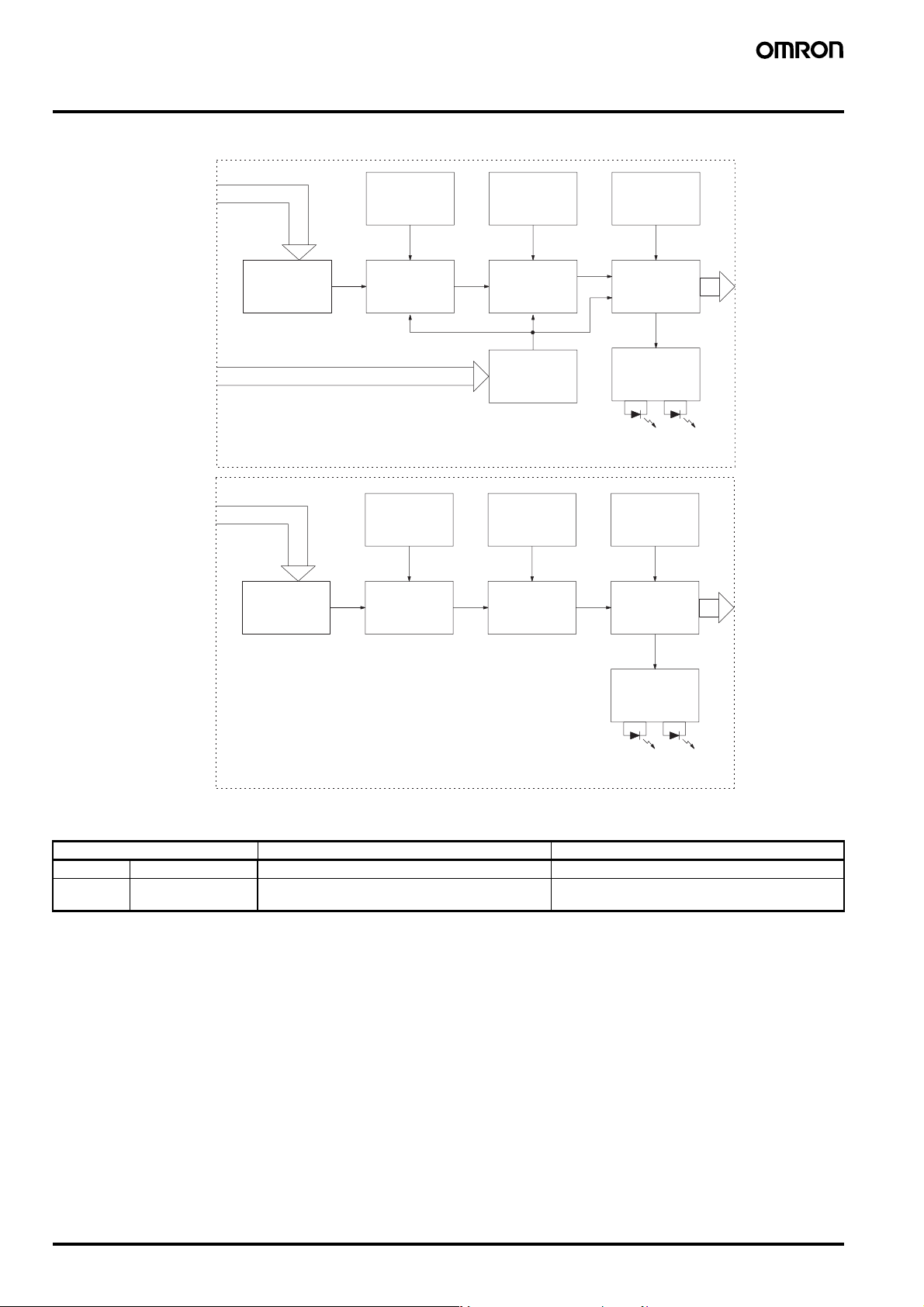
■ Block Diagram
H3DE-M1/-M2
AC (DC) input
Zero setting
detection
circuit
Time scale/
unit selectors
Operating
mode selector
H3DE-S1/-S2
Power supply
circuit
AC (DC) input
Power supply
circuit
Start input
Oscillation
circuit
Zero setting
detection
circuit
Oscillation
circuit
Counting
circuit
Input circuit
Time scale/
unit selectors
Counting
circuit
Output circuit
Indicator
circuit
Power-ON
indicator
Operating
mode selector
Output circuit
Indicator
circuit
Output
indicator
Powe r-ON
indicator
Output
indicator
■ I/O Functions
Item H3DE-M1/-M2 H3DE-S1/-S2
Input Start Starts operation. No input is available.
Output Control output Outputs are turned ON according to designated out-
put mode when preset value is reached. (See note.)
Note: When the output type selector switch on the bottom of the Timer is set to the instantaneous side, the relay R2 (terminal numbers 21/25, 22/
26, and 24/28) becomes an instantaneous contact and turns ON/OFF in synchronization with the changes in the power supply.
Outputs are turned ON according to designated output mode when preset value is reached. (see note.)
B-56 Solid-state Multi-functional Timer H3DE-M/-S
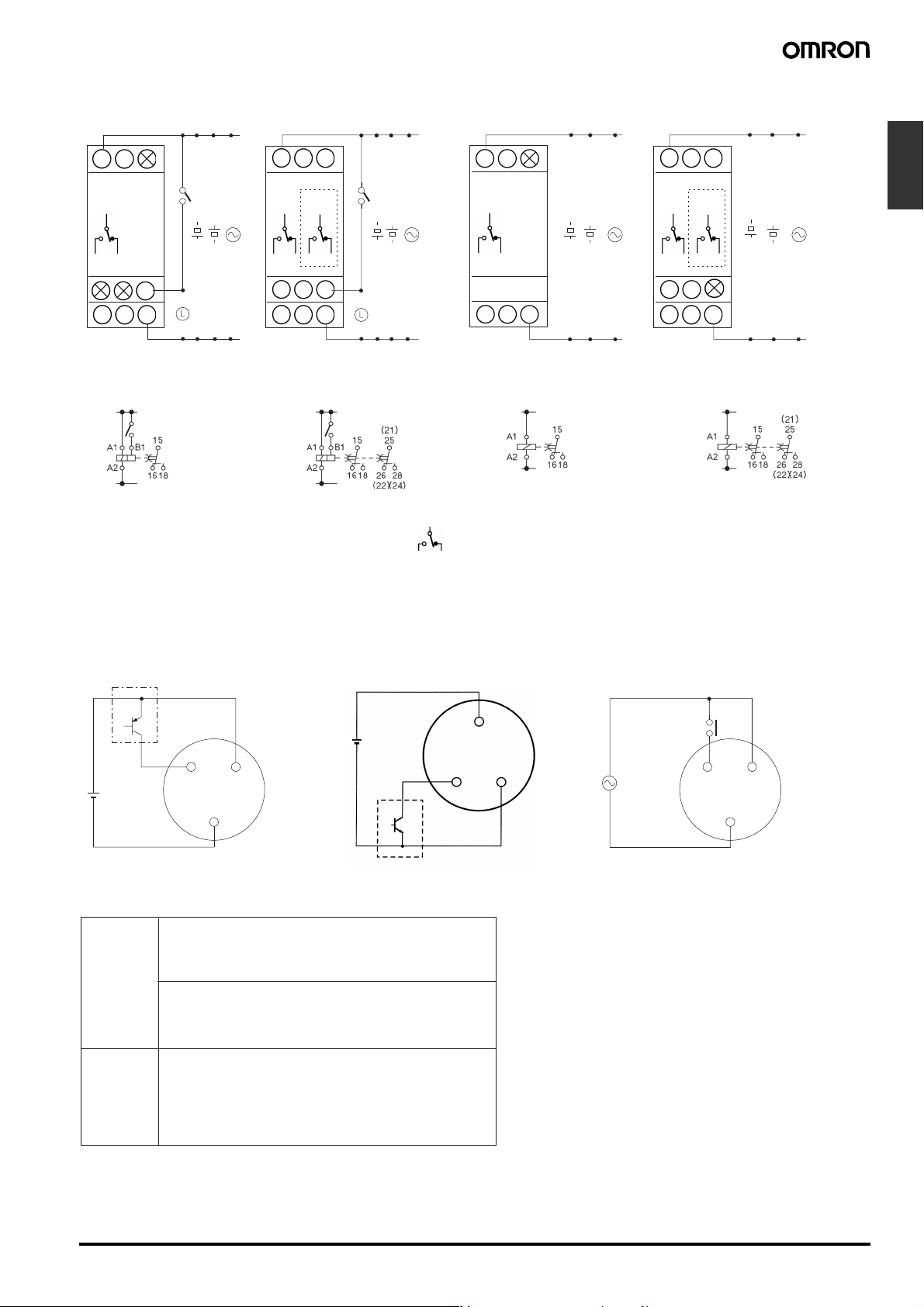
■ Terminal Arrangement
H3DE-M1 H3DE-S1H3DE-M2 H3DE-S2
A1 15
R1
15
18 16
18 16 A2
25
R1 R2
25/2115
28
/2426/22
/2426/22
/21
B1
-------------------------------------------------
-------------------------------------------------
-------------------------------------------------
------------
A1 15
18 16
B1
------------
-------------------------------------------------
-------------------------------------------------
(see note 2) (see note 2) (see note 2) (see note 2)
28
18 16 A2
-------------------------------------------------
A1 15
R1
15
18 16
18 16 A2
18 16
-------------------------------------------------
-------------------------------------------------
-------------------------------------------------
25
A1 15
(see note 1)(see note 1)
R1 R2
25/2115
28
/2426/22
28
/2426/22
18 16 A2
/21
-------------------------------------------------
-------------------------------------------------
(DIN notation) (DIN notation) (DIN notation) (DIN notation)
Note: 1. The relay R2 can be set to either instantaneous or time-limit contact using the switch located on the bottom of the Timer.
2. DC supply voltage does not require the designation of polarity.
3. The contact symbol for the H3DE is indicated with because it offers multiple operating modes and is different from the delayed
contact for conventional timers.
■ Input Connections
The inputs of the H3DE-M1/-M2 are voltage (voltage imposition or open) inputs.
Timers
-------------------------------------------------
No-contact Input
(Connection to PNP output sensor.)
No-contact Input
(Connection to NPN output sensor.)
Contact Input
Sensor
Timer
A
B1
2
A
1
(+)
24 VDC
(−)
(+)
24 VDC
(−)
Operates with PNP transistor ON Operates with relay ON
B1
Start Start
A1
A2
Sensor
Operates with NPN transistor ON
Voltage Input Signal Levels
1. Transistor ON
Residual voltage: 1 V max.
No-contact
input
(Voltage between terminals B
the rated "H-level" voltage (20.4 VDC min.).)
1 and A2 must be more than
2. Transistor OFF
Leakage current: 0.01 mA max.
(Voltage between terminals B
1 and A2 must be less than
the rated "L-level" voltage (2.4 VDC max.).)
Use contacts that can adequately switch 0.1 mA at each
Contact
input
voltage to be imposed. (When the contacts are ON or
OFF, voltage between terminals B
1 and A2 must be within
the following ranges:
When contacts are ON: 20.4 to 253 VAC/DC
When contacts are OFF: 0 to 2.4 VAC/DC
B1
TimerTimer
A1
A2
Solid-state Multi-functional Timer H3DE-M/-S B-57
Operation
■ Basic Operation
Setting of Selector
The selectors can be turned clockwise and counterclockwise to
select the desired time unit, time scale, or operating mode.
Each selector has a snap mechanism that secures the selector at a
given position. Set the selector at a position at which it is secured. Do
not set it midway between two securing positions or a malfunction
could result from improper setting.
Operating
mode selector
Operating
mode display
window
Selection of Time Unit and Time Scale
The desired time unit (s, m, h, or 10h) can be displayed in the time
unit display window above the time setting dial by turning the time
unit selector located at the upper right corner of the front panel. Time
scale (0.1 or 1) is selected with the time scale selector at the upper
left corner of the front panel, it appears in the time scale display window above the selector.
Time unit display
Time scale display
window
Time scale
selector
window
Selection of Operating Mode
The H3DE-M/-S can be set to any one of the operating modes A to J.
Turn the operating mode selector with a screwdriver until the desired
operating mode (A, B, C, B2, D, E, J, or G for the H3DE-M and A, E,
J, or B2 for the H3DE-S) appears in the operating mode display window located below the selector.
Time unit selector
B-58 Solid-state Multi-functional Timer H3DE-M/-S
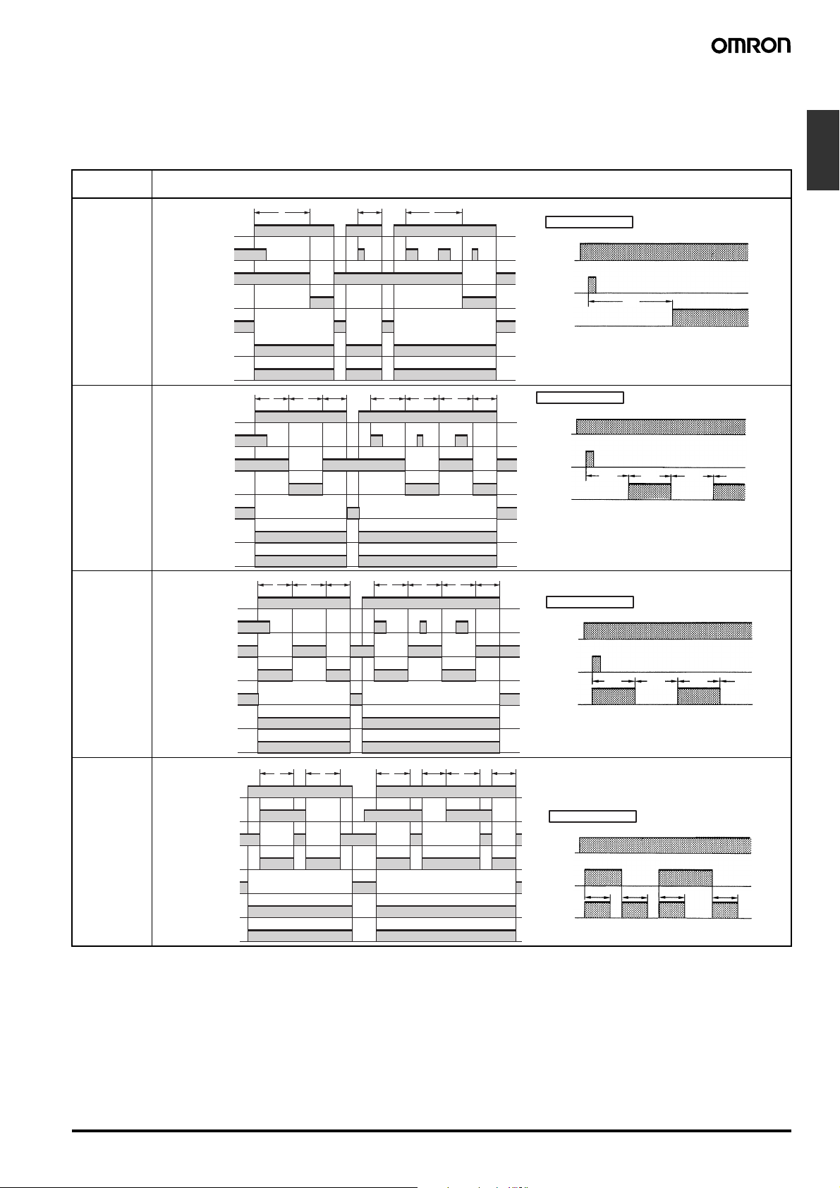
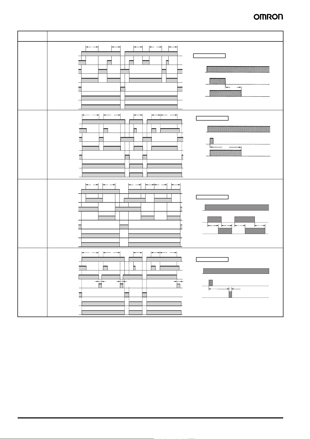
■ Timing Chart
Note: 1. The minimum power reset time is 0.1 s and the minimum signal input time is 0.05 s.
2. The letter “t” in the timing charts stands for the set time and “t–a” means that the period is less than the time set.
3. There is no start input with H3DE-S@ models. Operation starts when the power is turned ON.
4. There is no instantaneous output with H3DE-M1/-S1 models.
Operating
mode
A: ON-delay
t
t−a
Power (A1 and A2)
Start (B1 and A2)
(see note)
Time-limit contacts: NC
15 and 16 (25 and 26)
Time-limit contacts: NO
(output indicator)
15 and 18 (25 and 28)
Instantaneous contacts:
NC 25 and 26
Instantaneous contacts:
NO 25 and 28
Power indicator
B:
Flicker OFF
start
Power (A
1 and A2)
1 and A2)
Start (B
(see note)
Output relay: NC 15
and 16 (25 and 26)
Output relay: NO
(output indicator)
15 and 18 (25 and 28)
Instantaneous contacts:
NC 25 and 26
Instantaneous contacts:
NO 25 and 28
tt ttt
t−at−a
Power indicator
B2:
Flicker ON
start
Power (A
1 and A2)
1 and A2)
Start (B
(see note)
Output relay: NC 15
and 16 (25 and 26)
Output relay: NO
(output indicator)
15 and 18 (25 and 28)
Instantaneous contacts:
NC 25 and 26
Instantaneous contacts:
NO 25 and 28
tt ttt
t−at−a
Power indicator
C:
Signal ON/
OFFdelay
Power (A
1 and A2)
1 and A2)
Start (B
(see note)
Output relay: NC 15
and 16 (25 and 26)
Output relay: NO
(output indicator)
15 and 18 (25 and 28)
Instantaneous contacts:
NC 25 and 26
Instantaneous contacts:
NO 25 and 28
tttt
Power indicator
Note: The start input of the H3DE-M1 or H3DE-M2 model is activated by applying a voltage to B1 and A2 terminals.
The voltage can be applied by turning on the contact between B1 and A1 (Refer to Terminal Arrangement)
Timing chart
t
t−at−a
Basic operation
Powe r
**
*
Start
t
Output
* For power-on operation, impose voltage to the
Start input. The Timer starts operating at the
moment the power is turned on.
** Start input is invalid while the Timer is in opera-
tion.
Basic operation
Powe r
**
*
Start
t t t t
Output
* For power-on operation, impose voltage to the
Start input. The Timer starts operating at the
moment the power is turned on.
** Start input is invalid while the Timer is in opera-
tion.
Basic operation
Powe r
**
*
Start
t
Output
* For power-on operation, impose voltage to the
Start input. The Timer starts operating at the
moment the power is turned on.
** Start input is invalid while the Timer is in opera-
tion.
Basic operation
Powe r
*
Start
Output
* Start input is valid and re-triggerable while the
Timer is in operation.
tttt
Timers
t
t t
Solid-state Multi-functional Timer H3DE-M/-S B-59
.
Operating
mode
D:
Signal OFFdelay
E: Interval
G:
Signal ON/
OFFdelay
J:
One-shot output
(ON delay)
Power (A1 and A2)
1 and A2)
Start (B
(see note)
Output relay: NC 15
and 16 (25 and 26)
Output relay: NO
(output indicator)
15 and 18 (25 and 28)
Instantaneous contacts:
NC 25 and 26
Instantaneous contacts:
NO 25 and 28
Power indicator
Power (A1 and A2)
Start (B
1 and A2)
(see note)
Output relay: NC 15
and 16 (25 and 26)
Output relay: NO
(output indicator)
15 and 18 (25 and 28)
Instantaneous contacts:
NC 25 and 26
Instantaneous contacts:
NO 25 and 28
Power indicator
Power (A1 and A2)
Start (B1 and A2)
(see note)
Output relay: NC 15
and 16 (25 and 26)
Output relay: NO
(output indicator)
15 and 18 (25 and 28)
Instantaneous contacts:
NC 25 and 26
Instantaneous contacts:
NO 25 and 28
Power indicator
Power (A1 and A2)
Start (B1 and A2)
(see note)
Output relay: NC 15
and 16 (25 and 26)
Output relay: NO
(output indicator)
15 and 18 (25 and 28)
Instantaneous contacts:
NC 25 and 26
Instantaneous contacts:
NO 25 and 28
Power indicator
tt
tt
tttt
tt
Approx.
1+0.6 s
(fixed)
t−at−at−a
Approx.
1+0.6 s
(fixed)
Timing chart
t−at−a
t
t−at−a
t−at−a
t
Approx.
1+0.6 s
(fixed)
Basic operation
Powe r
*
Start
Output
* Start input is valid and re-triggerable while the
Timer is in operation.
Basic operation
Powe r
**
*
Start
t
Output
* For power-on operation, impose voltage to the
Start input. The Timer starts operating at the
moment the power is turned on.
** Start input is valid and re-triggerable while the
Timer is in operation.
Basic operation
Powe r
*
Start
t t t t
Output
* Start input is valid and re-triggerable while the
Timer is in operation.
Basic operation
Powe r
**
*
Start
Output
* For power-on operation, impose voltage to the
** Start input is valid and re-triggerable while the
t
Start input. The Timer starts operating at the
moment the power is turned on.
Timer is in operation.
Note: The start input of the H3DE-M1 or H3DE-M2 model is activated by applying a voltage to B1 and A2 terminals.
The voltage can be applied by turning on the contact between B1 and A1 (Refer to Terminal Arrangement).
t
Approx. 1+0.6 s
(fixed)
B-60 Solid-state Multi-functional Timer H3DE-M/-S
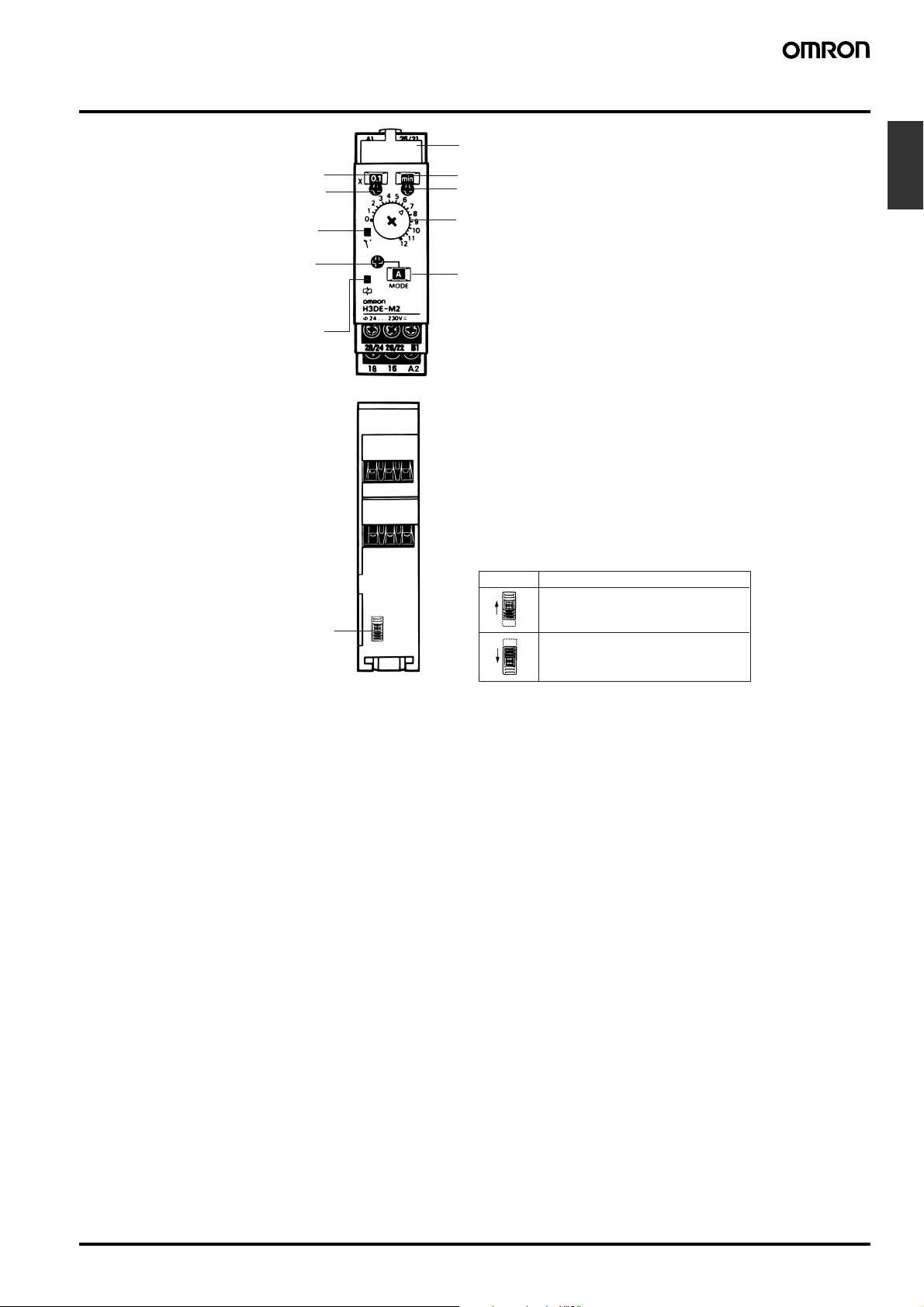
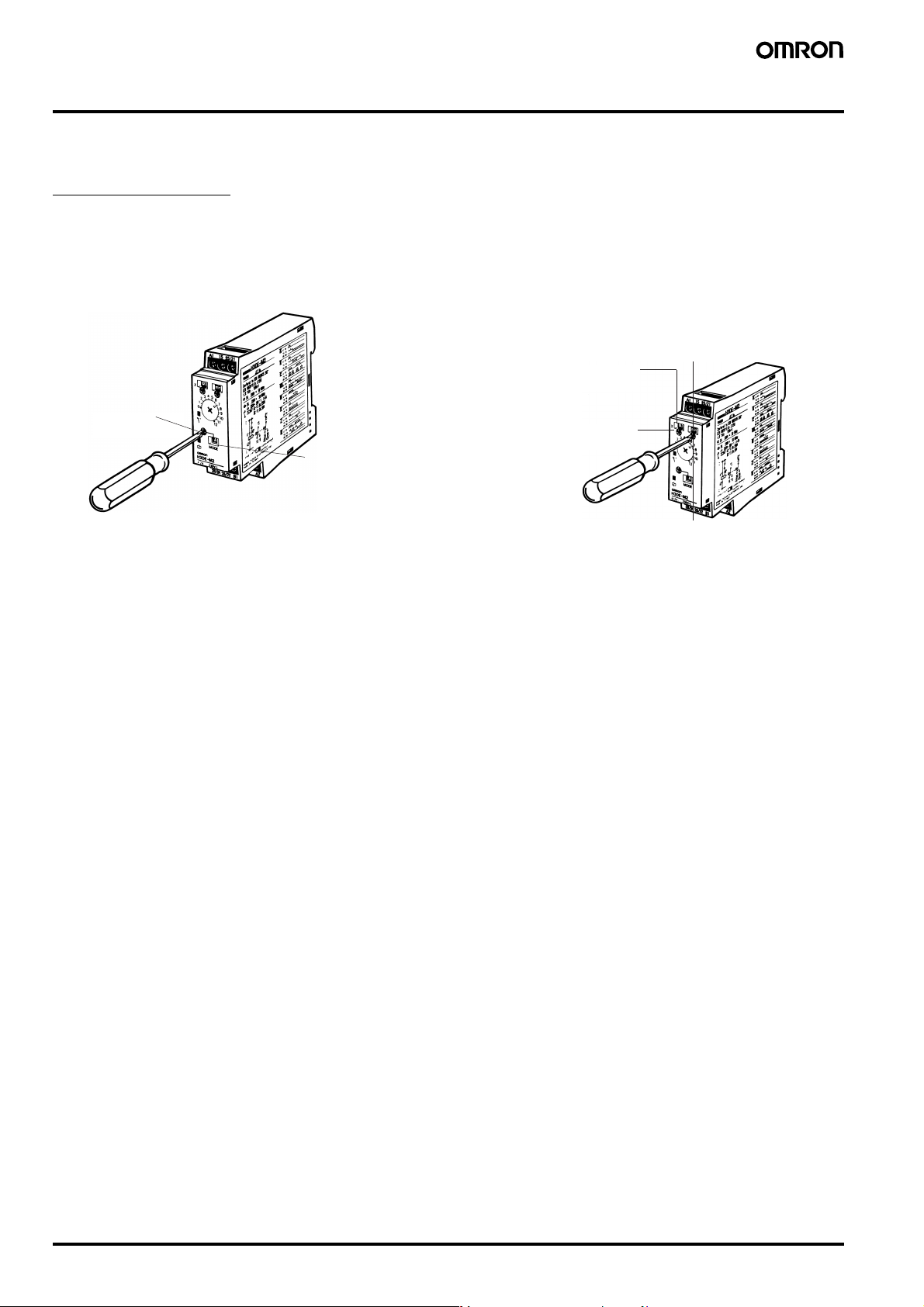
Nomenclature
Time scale display window
Time scale selector
(select 0.1 or 1)
Output indicator (orange)
(Lit while Timer gives output.)
Operating mode selector
(select a mode from A, B, C,
B2, D, E, J, and G for the
H3DE-M1/-M2, from A, E, J,
and B2 for the H3DE-S1/S2)
Power-on indicator (green)
(Lit while the power is on.)
(Front View)
Nameplate for user use (20
x 5.4 mm white panel)
Time unit display window
Time unit selector (select one from
sec, min, hrs, and 10 h)
Main dial (for setting a time value)
Operating mode display window
Timers
Output type selector switch for
H3DE-M2/-S2 (default setting
is time-limit output)
(Bottom View)
Output Type Selector Switch Settings
Setting Output type
Time-limit output (terminal numbers 25, 26 and
28) (default setting)
Instantaneous output
(terminal numbers 21, 22 and 24)
Solid-state Multi-functional Timer H3DE-M/-S B-61
 Loading...