


Solid-state Timer |
|
H3CR-F/G/H |
|
|
|
|
|
|
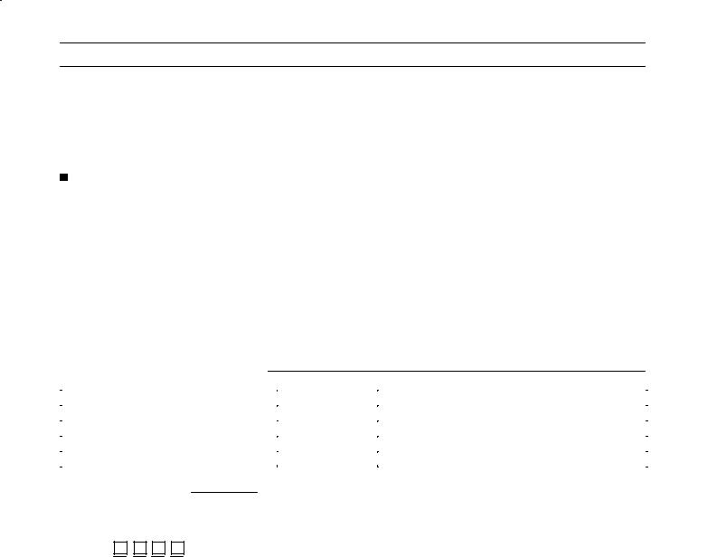
A Wide Variety of DIN 48 x 48-mm H3CR-F Twin Timers, H3CR-G Star-delta Timers, and H3CR-H Power OFF-delay Timers
Conforms to VDE0435/0110 and approved by UL and CSA.
Conforms to EMC standards.
Six-language instruction manual provided.

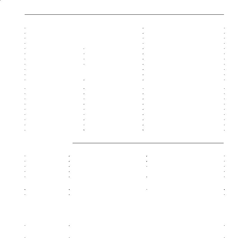
 Broad Line-up of H3CR Series
H3CR
|
|
|
|
|
|
|
|
|
|
|
|
|
|
|
|
H3CR-A |
H3CR-F |
H3CR-G |
H3CR-H |
||||
|
|
|
|
|
|
|
|
Multifunctional Timer
H3CR-A |
11-pin model |
|
H3CR-AS |
||
|
||
H3CR-A8 |
8-pin model |
|
H3CR-A8S |
|
|
H3CR-A8E |
8-pin with |
|
H3CR-A8EL |
instantaneous |
|
|
contact output |
|
|
model |
Twin Timer |
Star-delta Timer |
Power OFF-delay Timer |
|||
H3CR-F |
H3CR-G8L |
8-pin model |
H3CR-HRL |
|
11-pin model |
|
|||||
H3CR-FN |
11-pin model H3CR-G8EL |
H3CR-H8L |
|
||
|
8-pin model |
||||
H3CR-F-300 |
|
|
H3CR-H8RL |
||
H3CR-FN-300 H3CR-F8
H3CR-F8N
8-pin model
H3CR-F8-300
H3CR-F8N-300
Note: 1. H3CR-AS, H3CR-A8S: Transistor output models
2. Refer to the H3CR-A Datasheet (L84) for details.
1
H3CR-F 

 H3CR-F
Solid-state Twin Timers |
|
H3CR-F |
|
|
|
|
|
|
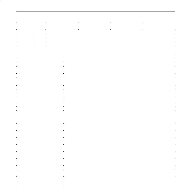
DIN 48 x 48-mm Solid-state Twin Timers
Wide power supply ranges of 100 to 240 VAC and 48 to 125 VDC respectively.
Independent ONand OFF-time settings. Furthermore, combinations of long ONor OFF-time and short OFFor ON-time settings are possible.
Fourteen time ranges from 0.05 s to 30 h or from 1.2 s to 300 h depending on the model to be used.
Models with a flicker ON start or flicker OFF start are available.
Easy sequence checks through instantaneous outputs for a zero set value at any time range.
Only 80 mm long when panel-mounted with a socket.
|
|
11-pin and 8-pin models are available. |
|
|
RC |
|
|||
|
|
|
|
|
|||||
|
|
|
|
|
|
|
|
|
|
|
|
|
|
|
|
|
|
|
|
Ordering Information |
|
|
|
|
|
||||
|
|
|
|
|
|||||
|
|
|
|
|
|
|
|
|
|
|
|
|
|
|
|
|
|
|
|
|
|
Operating |
Supply voltage |
|
0.05 s to 30 h models |
1.2 s to 300 h models |
|
||
|
|
modes |
|
|
|
|
|
|
|
|
|
|
11-pin models |
8-pin models |
11-pin models |
8-pin models |
|
||
|
|
|
|
|
|||||
|
|
|
|
|
|
|
|
||
|
Flicker OFF start |
100 to 240 VAC |
H3CR-F |
H3CR-F8 |
H3CR-F-300 |
H3CR-F8-300 |
|
||
|
|
|
|
|
|
|
|
|
|
|
|
|
24 VAC/DC |
|
|
|
|
|
|
|
|
|
|
|
|
|
|
|
|
|
|
|
12 VDC |
|
|
|
|
|
|
|
|
|
|
|
|
|
|
|
|
|
|
|
48 to 125 VDC |
|
|
|
|
|
|
|
|
|
|
|
|
|
|
||
|
Flicker ON start |
100 to 240 VAC |
H3CR-FN |
H3CR-F8N |
H3CR-FN-300 |
H3CR-F8N-300 |
|
||
|
|
|
|
|
|
|
|
|
|
|
|
|
24 VAC/DC |
|
|
|
|
|
|
|
|
|
|
|
|
|
|
|
|
|
|
|
12 VDC |
|
|
|
|
|
|
|
|
|
|
|
|
|
|
|
|
|
|
|
48 to 125 VDC |
|
|
|
|
|
|
Note: Specify both the model number and supply voltage when ordering.
Example: H3CR-F 24 VAC/DC
 Supply voltage
Model Number Legend:
H3CR - |
|
|
|
|
|
- |
|
|
|
|
|
1 |
2 |
|
3 |
4 |
|
|
|||
1. |
Classification |
|
|
|
3. Twin Timer Mode |
|||||
F: |
Twin timers |
|
|
|
None: Flicker OFF start |
|||||
2. |
Configuration |
|
|
|
N: |
Flicker ON start |
||||
|
|
|
4. Specified Type |
|||||||
None: 11-pin socket |
|
|
|
|||||||
8: |
8-pin socket |
|
300: |
Long time range (1.2 s to 300 h) type |
||||||
2

H3CR-F 

 H3CR-F

 Accessories (Order Separately)
|
Name/specifications |
Models |
|
|
|
|
|
Flush Mounting Adapter |
|
|
Y92F-30 |
|
|
|
|
|
|
|
Y92F-73 |
|
|
|
|
|
|
|
Y92F-74 |
|
|
|
|
Mounting Track |
|
50 cm (l) x 7.3 mm (t) |
PFP-50N |
|
|
|
|
|
|
1 m (l) x 7.3 mm (t) |
PFP-100N |
|
|
|
|
|
|
1 m (l) x 16 mm (t) |
PFP-100N2 |
|
|
|
|
End Plate |
|
|
PFP-M |
|
|
|
|
Spacer |
|
|
PFP-S |
|
|
|
|
Protective Cover |
|
|
Y92A-48B |
|
|
|
|
Track Mounting/ |
|
8-pin |
P2CF-08 |
Front Connecting Socket |
|
|
|
|
11-pin |
P2CF-11 |
|
|
|
||
|
|
|
|
Back Connecting Socket |
|
8-pin |
P3G-08 |
|
|
|
|
|
|
11-pin |
P3GA-11 |
|
|
|
|
Hold-down Clip |
|
For PL08 and PL11 Sockets |
Y92H-7 |
|
|
|
|
|
|
For PF085A Socket |
Y92H-8 |
Specifications

 General
Item |
H3CR-F |
|
|
H3CR-F8 |
|
H3CR-FN |
|
H3CR-F8N |
|
|
|
|
|
|
|
|
|
Operating mode |
Flicker OFF start |
|
|
|
Flicker ON start |
|
||
|
|
|
|
|
|
|
||
Pin type |
11-pin |
|
8-pin |
|
|
11-pin |
|
8-pin |
|
|
|
|
|
|
|
||
Operating/Reset method |
Time-limit operation/Time-limit reset or self-reset |
|
|
|
|
|||
|
|
|
|
|
|
|
|
|
Output type |
Relay output (DPDT) |
|
|
|
|
|
|
|
|
|
|
||||||
Mounting method |
DIN track mounting, surface mounting, and flush mounting |
|
||||||
|
|
|
|
|
||||
EMC |
Emission Enclosure: |
|
EN55011 Group 1 class A |
|
||||
|
Emission AC Mains: |
|
EN55011 Group 1 class A |
|
||||
|
Immunity ESD: |
|
IEC801-2: |
4 kV contact discharge (level 2) |
||||
|
|
|
|
|
8 kV air discharge (level 3) |
|
||
|
Immunity RF-interference: |
|
ENV50140: |
10 V/m (80 MHz to 1 GHz) (level 3) |
||||
|
Immunity Conducted Disturbance: |
ENV50141: |
10 V (0.15 to 80 MHz) (level 3) |
|
||||
|
Immunity Burst: |
|
IEC801-4: 2 kV power-line (level 3) |
|
||||
|
|
|
|
|
2 kV I/O signal-line (level 4) |
|
||
|
|
|
|
|
|
|
||
Approved standards |
UL508, CSA C22.2 No.14, LR/NK |
|
|
|
|
|
||
|
Conforms to VDE0435/2021, VDE0110 |
|
|
|
|
|||
|
Conforms to EN50081-2, prEN50082-2 |
|
|
|
|
|||

 Time Ranges
0.05 s to 30 h Models
Time unit |
|
s (sec) |
x10 s (10 s) |
min |
h (hrs) |
|
|
|
|
|
|
Setting |
1.2 |
0.05 to 1.2 |
1.2 to 12 |
0.12 to 1.2 |
|
|
|
|
|
|
|
|
3 |
0.3 to 3 |
3 to 30 |
0.3 to 3 |
|
|
|
|
|
|
|
|
12 |
1.2 to 12 |
12 to 120 |
1.2 to 12 |
|
|
|
|
|
|
|
|
30 |
3 to 30 |
30 to 300 |
3 to 30 |
|
Note: Instantaneous output is available at any time range. To obtain instantaneous output, set to below 0. |
|
||||
1.2 s to 300 h Models |
|
|
|
|
|
Time unit |
|
x10 s (10 s) |
x10 min (10 min) |
h (hrs) |
x10 h (10 h) |
|
|
|
|
|
|
Setting |
1.2 |
1.2 to 12 |
1.2 to 12 |
0.12 to 1.2 |
1.2 to 12 |
|
|
|
|
|
|
|
3 |
3 to 30 |
3 to 30 |
0.3 to 3 |
3 to 30 |
|
|
|
|
|
|
|
12 |
12 to 120 |
12 to 120 |
1.2 to 12 |
12 to 120 |
|
|
|
|
|
|
|
30 |
30 to 300 |
30 to 300 |
3 to 30 |
30 to 300 |
Note: Instantaneous output is available at any time range. To obtain instantaneous output, set to below 0.
3
|
H3CR-F |
|
|
|
|
H3CR-F |
|||
|
|
|
|||||||
|
|
|
|
||||||
|
|
|
|
|
|
|
|
|
|
|
|
|
|
|
|
|
|
|
|
|
|
Ratings |
|
|
|
|
|
|
|
|
|
|
|
|
|
|
|
||
|
|
|
|
|
|
|
|
||
|
|
|
|
||||||
|
Rated supply voltage (see note) |
100 to 240 VAC (50/60 Hz),12 VDC, 24 VAC/DC (50/60 Hz), 48 to 125 VDC |
|
||||||
|
|
|
|
||||||
|
Operating voltage range |
85% to 110% of rated supply voltage; 90% to 110% with 12-VDC models |
|
||||||
|
|
|
|
||||||
|
Power reset |
Minimum power-opening time: 0.1 s |
|
||||||
|
|
|
|
||||||
|
Power consumption |
100 to 240 VAC: approx. 10 VA; 12 VDC: approx. 1 W; |
|
||||||
|
|
|
|
24 VAC/DC: approx. 2 VA (AC), approx. 1 W (DC); 48 to 125 VDC: approx. 1.5 W |
|
||||
|
|
|
|
||||||
|
Control outputs |
Contact output: 5 A at 250 VAC, resistive load (cosφ = 1) |
|
||||||
Note: A power supply with a ripple of 20% max. (single-phase power supply with full-wave rectification) can be used with each DC Model.

 Characteristics
Accuracy of operating time |
± 0.3% FS max. (± 0.3% FS ± 10 ms in ranges of 1.2 and 3 s) |
|
|
Setting error |
± 5% FS ± 0.05 s max. |
|
|
Reset time |
0.1 s max. |
|
|
Influence of voltage |
± 0.5% FS max. (± 0.5% FS ± 10 ms in ranges of 1.2 and 3 s) |
|
|
Influence of temperature |
± 2% FS max. (± 2% FS ± 10 ms in ranges of 1.2 and 3s) |
Insulation resistance |
100 MΩ min. (at 500 VDC) |
Dielectric strength |
2,000 VAC, 50/60 Hz for 1 min (between current-carrying metal parts and exposed |
|
non-current-carrying metal parts) |
|
2,000 VAC, 50/60 Hz for 1 min (between control output terminals and operating circuit) |
|
1,000 VAC, 50/60 Hz for 1 min (between contacts not located next to each other) |
|
|
Impulse withstand voltage |
3 kV (between power terminals) for 100 to 240 VAC, 48 to 125 VDC |
|
1 kV for 12 VDC, 24 VAC/DC |
|
4.5 kV (between current-carrying terminal and exposed non-current-carrying metal parts) |
|
for 100 to 240 VAC, 48 to 125 VDC |
|
1.5 kV for 12 VDC, 24 VAC/DC |
|
|
Noise immunity |
± 1.5 kV (between power terminals), square-wave noise by noise simulator (pulse width: |
|
100 ns/1 µ s, 1-ns rise) |
|
± 400 V for 12 VDC |
Static immunity |
Malfunction: 8 kV |
|
Destruction: 15 kV |
|
|
Vibration resistance |
Destruction:10 to 55 Hz with 0.75-mm single amplitude each in three directions |
|
Malfunction:10 to 55 Hz with 0.5-mm single amplitude each in three directions |
|
|
Shock resistance |
Destruction: 980 m/s2 (100G) each in three directions |
|
Malfunction: 98 m/s2 (10G) each in three directions |
Ambient temperature |
Operating:–10° C to 55° C (with no icing) |
|
Storage: –25° C to 65° C (with no icing) |
Ambient humidity |
Operating: 35% to 85% |
|
|
Life expectancy |
Mechanical:20 million operations min. (under no load at 1,800 operations/h) |
|
Electrical: 100,000 operations min. (5 A at 250 VAC, resistive load at 1,800 operations/h) |
Case color |
Light Gray (Munsell 5Y7/1) |
|
|
Enclosure ratings |
IEC: IP40 |
|
|
Weight |
Approx. 100 g |
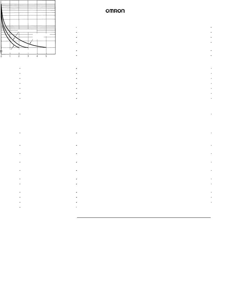
Engineering Data
) |
10,000 |
|
|
|
|
3 |
5,000 |
|
(x 10 |
|
|
|
|
|
operations |
1,000 |
|
|
|
|
|
|
|
|
|
30 VDC L/R = 7 ms |
Switching |
500 |
|
250 VAC/30 VDC (cosf = 1)
100
250 VAC (cosf = 0.4)
Reference: A maximum current of 0.15 A can be switched at 125 VDC (cosf = 1) and a maximum current of 0.1 A can be switched if L/R is 7 ms. In both cases, a life of 100,000 operations can be expected.
The minimum applicable load is 10 mA at 5 VDC (failure level: P).
Load current (A)
4
H3CR-F 

 H3CR-F
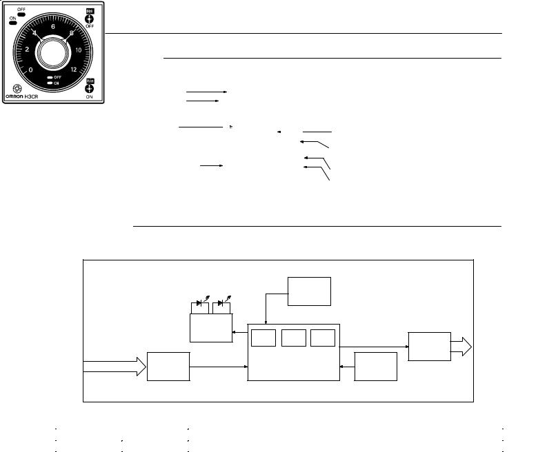
Nomenclature
OFF indicator (green)
Lit when the output is OFF.
ON indicator (orange)
Lit when the output is ON.
Scale range display windows
Time range selector (select one from 1.2, 3, 12, and 30)
For both ON-time and OFF-time.
 OFF-time unit display window
 OFF-time unit selector (select one from sec. 10 s, min., and hrs, or from 10 s, 10 min, hrs, and 10 h)
ON-time setting knob (with orange pointer)
For ON-time setting
OFF-time setting knob (with green pointer)
For OFF-time setting
ON-time unit display window
ON-time unit selector (select one from sec. 10 s, min., and hrs, or from 10 s, 10 min, hrs, and 10 h)
Operation

 Block Diagrams
|
ON indicator |
OFF indicator |
Zero setting |
|
||
|
detection |
|
||||
|
|
|
circuit |
|
|
|
|
Indicator |
|
|
|
|
|
|
circuit |
|
|
|
|
|
|
|
ROM |
RAM |
Clock |
Output |
|
|
|
|
|
|
||
|
|
|
|
|
circuit |
|
AC (DC) input |
Power supply |
One-chip microcomputer |
Time range/unit |
|||
circuit |
selectors |
|||||
|
|
|
||||

 I/O Functions
Inputs |
|
--- |
|
|
|
Outputs |
Control output |
Outputs are turned ON/OFF according to the time set by the ONand OFF-time setting knob. |
5
H3CR-F 

 H3CR-F
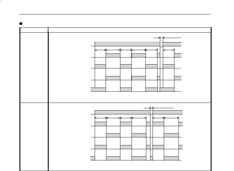
Timing Chart |
|
|
|
|
|
|
Operating mode |
|
|
Timing chart |
|
|
|
Flicker OFF start |
|
|
|
|
|
0.1 s min. |
|
|
|
|
|
|
|
Power |
ON |
|
|
|
|
|
OFF |
|
|
|
|
|
|
|
|
|
|
|
|
|
|
tOFF |
tON |
tOFF |
tON |
tOFF |
tOFF |
ON |
Lit |
|
|
|
|
|
indicator |
Not lit |
|
|
|
|
|
|
|
|
|
|
|
|
OFF |
Lit |
|
|
|
|
|
indicator |
Not lit |
|
|
|
|
|
Output |
ON |
|
|
|
|
|
NO |
OFF |
|
|
|
|
|
Output |
ON |
|
|
|
|
|
NC |
OFF |
|
|
|
|
|
|
tON: ON set time |
|
|
|
|
|
|
tOFF: OFF set time |
|
|
|
|
|
Flicker ON start |
|
|
|
|
0.1 s min. |
|
|
|
|
|
|
|
|
Power |
ON |
|
|
|
|
|
OFF |
|
|
|
|
|
|
|
tOFF |
tON |
tOFF |
tON |
tOFF |
|
|
tON |
|||||
ON |
Lit |
|
|
|
|
|
|
|
|
|
|
|
|
indicator |
Not lit |
|
|
|
|
|
OFF |
Lit |
|
|
|
|
|
indicator |
Not lit |
|
|
|
|
|
|
|
|
|
|
|
|
Output |
ON |
|
|
|
|
|
NO |
OFF |
|
|
|
|
|
|
|
|
|
|
|
|
Output |
ON |
|
|
|
|
|
NC |
OFF |
|
|
|
|
|
|
tON: ON set time |
|
|
|
|
|
|
tOFF: OFF set time |
|
|
|
|
|
6

H3CR-F 

 H3CR-F
Dimensions
Note: All units are in millimeters unless otherwise indicated.
H3CR-F
H3CR-FN  48
48 

H3CR-F-300
H3CR-FN-300
48
H3CR-F8
48
H3CR-F8N H3CR-F8-300 H3CR-F8N-300
48
17.466.6
5.7 |
6 |
52.3 |
0.7 |
|
|
|
|
37 dia |
|
44.8 x 44.8 |
|
|
|
14 dia.
R1.3
17.466.6
5.7 |
6 |
52.3 |
0.7 |
|
|
|
|
37 dia |
|
44.8 x 44.8 |
|
|
14 dia.
R1.3
Installation

 Terminal Arrangement
H3CR-F8 |
H3CR-F |
H3CR-F8N |
H3CR-FN |
H3CR-F8-300 |
H3CR-F-300 |
H3CR-F8N-300 |
H3CR-FN-300 |
(–) |
(+) |
|
|
(~) |
(~) |
(–)(~) |
(+)(~) |
|
|
|
|
Power supply |
|
|
Power supply |
Note: Leave terminals 5, 6, and 7 open.
Do not use them as relay terminals.
7
H3CR-G 

 H3CR-G
Solid-state Star-delta Timer |
|
H3CR-G |
|
|
|
|
|
|
DIN 48 x 48-mm Solid-state Star-delta
Timer
A wide star-time range (up to 120 seconds) and star-delta transfer time range (up to 0.5 seconds).
RC
Ordering Information
Outputs |
Supply voltage |
8-pin models |
|
|
|
Time-limit contact |
100 to 120 VAC |
H3CR-G8L |
|
|
|
|
200 to 240 VAC |
|
|
|
|
Time-limit contact and instantaneous contact |
100 to 120 VAC |
H3CR-G8EL |
|
|
|
|
200 to 240 VAC |
|
Note: Specify both the model number and supply voltage when ordering.
Example: H3CR-G8L 100 to 120 VAC
 Supply voltage
Model Number Legend:
H3CR -
|
1 |
2 |
3 |
4 |
|
1. |
Classification |
|
3. |
Outputs |
|
G: Star-delta timer |
|
None: Star-delta operation contact |
|||
|
|
|
|
E: |
Star-delta operation contact and instantaneous contact |
2. |
Configuration |
|
4. |
Dimensions |
|
8: 8-pin socket |
|
|
L: Long-body model |
||
8
H3CR-G 

 H3CR-G

 Accessories (Order Separately)
|
Name/specifications |
Models |
|
|
|
|
|
Flush Mounting Adapter |
|
|
Y92F-30 |
|
|
|
|
|
|
|
Y92F-70 |
|
|
|
|
|
|
|
Y92F-71 |
|
|
|
|
Mounting Track |
|
50 cm (l) x 7.3 mm (t) |
PFP-50N |
|
|
|
|
|
|
1 m (l) x 7.3 mm (t) |
PFP-100N |
|
|
|
|
|
|
1 m (l) x 16 mm (t) |
PFP-100N2 |
|
|
|
|
End Plate |
|
|
PFP-M |
|
|
|
|
Spacer |
|
|
PFP-S |
|
|
|
|
Protective Cover |
|
|
Y92A-48B |
|
|
|
|
Track Mounting/ |
|
8-pin |
P2CF-08 |
Front Connecting Socket |
|
|
|
Back Connecting Socket |
|
|
P3G-08 |
|
|
|
|
Time Setting Ring |
|
Setting a specific time |
Y92S-27 |
|
|
|
|
|
|
Limiting the Setting Range |
Y92S-28 |
|
|
|
|
Panel Cover (see note) |
|
Light Gray (5Y7/1) |
Y92P-48GL |
|
|
|
|
|
|
Black (N1.5) |
Y92P-48GB |
|
|
|
|
|
|
Medium Gray (5Y5/1) |
Y92P-48GM |
|
|
|
|
Hold-down Clip |
|
For PL08 and PL11 Sockets |
Y92H-1 |
|
|
|
|
|
|
For PF085A Socket |
Y92H-2 |
Note: The Time Setting Ring and Panel Cover are sold together.
Specifications

 General
Item |
H3CR-G8L |
|
|
|
H3CR-G8EL |
|
|
|
|
|
|
Functions |
Star-delta timer |
|
|
Star-delta timer with instantaneous output |
|
|
|
|
|
|
|
Pin type |
8-pin |
|
|
|
|
|
|
|
|
|
|
Operating/Reset method |
Time-limit operation/Self-reset |
|
|
|
|
|
|
|
|
|
|
Output type |
Time-limit: SPST-NO (star operation circuit) |
|
Time-limit: |
SPST-NO (star operation circuit) |
|
|
SPST-NO (delta operation circuit) |
|
|
SPST-NO (delta operation circuit) |
|
|
|
|
|
Instantaneous: SPST-NO |
|
|
|
|
|
||
Mounting method |
DIN track mounting, surface mounting, and flush mounting |
|
|||
|
|
|
|
||
EMC |
Emission Enclosure: |
EN55011 Group 1 class A |
|
||
|
Emission AC Mains: |
EN55011 Group 1 class A |
|
||
|
Immunity ESD: |
IEC801-2: |
4 kV contact discharge (level 2) |
||
|
|
|
8 kV air discharge (level 3) |
||
|
Immunity RF-interference: |
ENV50140: |
10 V/m (80 MHz to 1 GHz) (level 3) |
||
|
Immunity Conducted Disturbance: ENV50141: 10 V (0.15 to 80 MHz) (level 3) |
||||
|
Immunity Burst: |
IEC801-4: |
2 kV power-line (level 3) |
||
|
|
|
2 kV I/O signal-line (level 4) |
||
|
|
|
|
|
|
Approved standards |
UL508, CSA C22.2 No.14, LR/NK |
|
|
|
|
|
Conforms to VDE0435/2021, VDE0110 |
|
|
|
|
|
Conforms to EN50081-2, prEN50082-2 |
|
|
|
|
9
H3CR-G 

 H3CR-G

 Time Ranges
Star-delta transfer |
0.05 sec |
0.1 sec |
0.25 sec |
0.5 sec |
|
time |
|
|
|
|
|
|
|
|
|
|
|
Star |
6 |
0.5 to 6 sec |
|
|
|
operation |
|
|
|
|
|
12 |
1 to 12 sec |
|
|
|
|
time setting |
|
|
|
||
|
|
|
|
|
|
60 |
5 to 60 sec |
|
|
|
|
|
|
|
|
||
|
|
|
|
|
|
|
120 |
10 to 120 sec |
|
|
|

 Ratings
Rated supply voltage |
100 to 120 |
VAC (50/60 Hz), 200 to 240 VAC (50/60 Hz) |
|
|
|
Operating voltage range |
85% to 110% of rated supply voltage |
|
|
|
|
Power reset |
Minimum power-opening time: 0.5 s |
|
|
|
|
Power consumption |
100 to 120 |
VAC: approx. 6 VA/2.4 W |
|
200 to 240 |
VAC: approx. 12 VA/2.6 W |
|
|
|
Control outputs |
Contact output: 5 A at 250 VAC, resistive load (cosφ = 1) |
|

 Characteristics
Accuracy of operating time |
± |
0.3% FS max. |
Setting error |
± 5% FS ± 0.05 s max. |
|
Star-delta transfer time |
Accuracy: ± 25% FS + 5 ms max. |
|
Influence of voltage |
± |
0.5% FS max. |
Influence of temperature |
± |
2% FS max. |
Insulation resistance |
100 MΩ min. (at 500 VDC) |
|
Dielectric strength |
2,000 VAC, 50/60 Hz for 1 min (between current-carrying metal parts and exposed |
|
|
non-current-carrying metal parts) |
|
|
2,000 VAC, 50/60 Hz for 1 min (between control output terminals and operating circuit) |
|
|
1,000 VAC, 50/60 Hz for 1 min (between contacts not located next to each other) |
|
|
|
|
Impulse withstand voltage |
3 kV (between power terminals) |
|
|
4.5 kV (between current-carrying terminal and exposed non-current-carrying metal parts) |
|
|
|
|
Noise immunity |
± 1.5 kV (between power terminals), square-wave noise by noise simulator (pulse width: |
|
|
100 ns/1 µ s, 1-ns rise) |
|
Static immunity |
Malfunction: 8 kV |
|
|
Destruction: 15 kV |
|
|
|
|
Vibration resistance |
Destruction:10 to 55 Hz with 0.75-mm single amplitude each in three directions |
|
|
Malfunction:10 to 55 Hz with 0.5-mm single amplitude each in three directions |
|
|
|
|
Shock resistance |
Destruction: 980 m/s2 (100G) each in three directions |
|
|
Malfunction: 294 m/s2 (30G) each in three directions |
|
Ambient temperature |
Operating:–10° C to 55° C (with no icing) |
|
|
Storage: –25° C to 65° C (with no icing) |
|
Ambient humidity |
Operating: 35% to 85% |
|
|
|
|
Life expectancy |
Mechanical:20 million operations min. (under no load at 1,800 operations/h) |
|
|
Electrical: 100,000 operations min. (5 A at 250 VAC, resistive load at 1,800 operations/h) |
|
|
|
|
Case color |
Light Gray (Munsell 5Y7/1) |
|
|
|
|
Enclosure ratings |
IEC: IP40 |
|
|
|
|
Weight |
H3CR-G8L: approx. 110 g; H3CR-G8EL: approx. 130 g |
|
10
 Loading...