

Page 1
3
Solid-state Timer H3CR
DIN 48 x 48-mm Multifunctional Timer Series
Conforms to EN61812-1 and EN60664-1
(VDE0110) 4 kV/2.
Conforms to EMC standards (EN50081-2 and
EN50082-2).
Approved by UL and CSA.
Lloyds/NK approvals.
Six-language instruction manual provided.
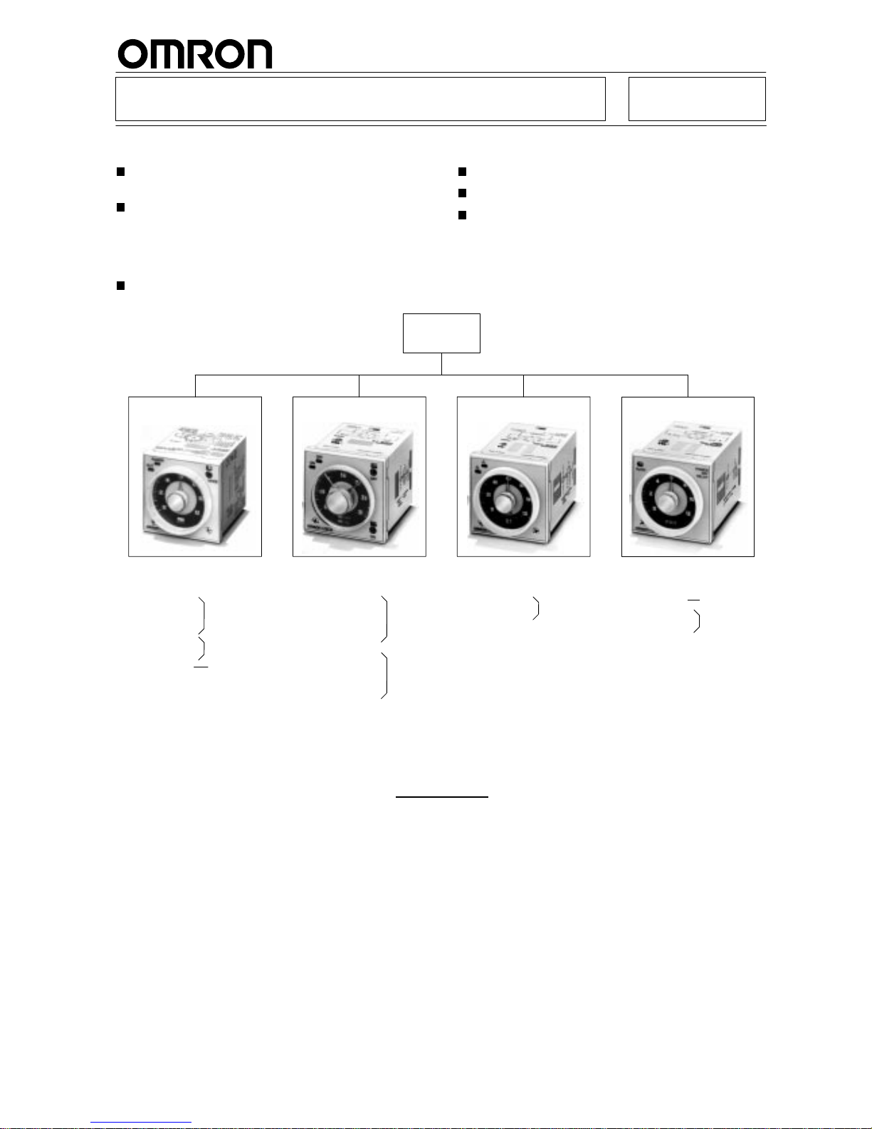
Broad Line-up of H3CR Series
H3CR
Multifunctional Timer
H3CR-A
H3CR-AS
H3CR-AP
H3CR-A8
H3CR-A8S
H3CR-A8E
Twin Timer
H3CR-F
H3CR-FN
H3CR-F-300
H3CR-FN-300
H3CR-F8
H3CR-F8N
H3CR-F8-300
H3CR-F8N-300
Star-delta Timer
H3CR-G8L
H3CR-G8EL
Power OFF-delay Timer
H3CR-HRL
H3CR-H8L
H3CR-H8RL
H3CR-HH3CR-GH3CR-F
Note: H3CR-AS, H3CR-A8S: T
ransistor output models
1
1-pin model
8-pin model
8-pin with
instantaneous
contact output
model
1
1-pin model
8-pin model
8-pin model
8-pin model
1
1-pin model
H3CR-A
Contents
Solid-state Timer
H3CR-A 4.
. . . . . . . . . . . . . . . . . . . . . . . . . . . . . . . . . . . . . . . . . . . . . . . . . . . . . . . . . . .
H3CR-F 23
. . . . . . . . . . . . . . . . . . . . . . . . . . . . . . . . . . . . . . . . . . . . . . . . . . . . . . . . . . . .
H3CR-G 29
. . . . . . . . . . . . . . . . . . . . . . . . . . . . . . . . . . . . . . . . . . . . . . . . . . . . . . . . . . . .
H3CR-H 36
. . . . . . . . . . . . . . . . . . . . . . . . . . . . . . . . . . . . . . . . . . . . . . . . . . . . . . . . . . . .
Common to ALL Timers
Operation 45.
. . . . . . . . . . . . . . . . . . . . . . . . . . . . . . . . . . . . . . . . . . . . . . . . . . . . . . . . .
Accessories 47
. . . . . . . . . . . . . . . . . . . . . . . . . . . . . . . . . . . . . . . . . . . . . . . . . . . . . . . .
Precautions 51
. . . . . . . . . . . . . . . . . . . . . . . . . . . . . . . . . . . . . . . . . . . . . . . . . . . . . . . . .
Page 2
H3CR-A
H3CR-A
4
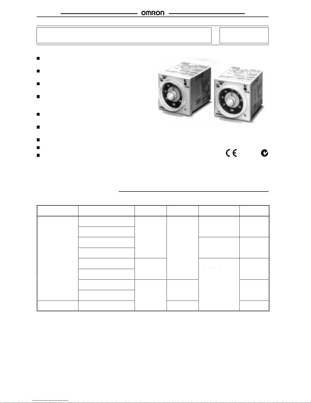
Solid-state Timer H3CR-A
DIN 48 x 48-mm State-of-the-art Multifunctional Timer
A
wider power supply range reduces the number of
timer models kept in stock.
A wide range of applications through six or four
operating modes.
Reduced power consumption.
(Except for H3CR-A8E)
Enables easy sequence checks through instanta-
neous outputs for a zero set value at any time
range.
Length, when panel-mounted with a Socket, of 80
mm or less.
Time
Setting
Rings enable consistent settings and
limit the setting range.
Panel Covers enable various panel designs.
PNP input models available.
Rich variety of inputs: Start, reset, and gate
functions (11-pin models and -AP models )
RC
Ordering Information
11-pin Models
Output Supply
voltage
Input type
T
ime range
Operating mode
(see note 2)
Model
Contact
100 to 240 V
AC (50/60 Hz)/
100 to 125 VDC
No-voltage input
0.05 s to 300 h
Six multi-modes: A,
B, B2, C, D, E
H3CR-A
24 to 48 V
AC (50/60 Hz)/
12 to 48 VDC
, ,,,
100 to 240 V
AC (50/60 Hz)/
100 to 125 VDC
Dual-modes: G, J
H3CR-A-300
24 to 48 V
AC (50/60 Hz)/
12 to 48 VDC
100 to 240 V
AC (50/60 Hz)/
100 to 125 VDC
V
oltage input
Six multi-modes: A,
B, B2, C, D, E
H3CR-AP
24 to 48 V
AC (50/60 Hz)/
12 to 48 VDC
, ,,,
100 to 240 V
AC (50/60 Hz)/
100 to 125 VDC
No-voltage input
0.1 s to 600 h
H3CR-A-301
24 to 48 V
AC (50/60 Hz)/
12 to 48 VDC
Transistor
(Photocoupler)
24 to 48 V
AC (50/60 Hz)/
12 to 48 VDC
0.05 s to 300 h
H3CR-AS
Page 3
H3CR-A
H3CR-A
5
8-pin Models
Output Supply
voltage
Input type
T
ime range
Operating mode
(see note 2)
Model
Contact
100 to 240 V
AC (50/60 Hz)/
100 to 125 VDC
No-input
available
0.05 s to 300 h
Four multi-modes: A,
B2, E, J
H3CR-A8
24 to 48 V
AC (50/60 Hz)/
12 to 48 VDC
,,
(Power supply start)
100 to 240 V
AC (50/60 Hz)/
100 to 125 VDC
0.1 s to 600 h
H3CR-A8-301
24 to 48 V
AC (50/60 Hz)/
12 to 48 VDC
Transistor
(Photocoupler)
24 to 48 V
AC (50/60 Hz)/
12 to 48 VDC
0.05 s to 300 h
H3CR-A8S
T
ime-limit contact
and instantaneous
100 to 240 V
AC (50/60 Hz)/
100 to 125 VDC
H3CR-A8E
contact
24 to 48 VDC/V
AC (50/60 Hz)
Note: 1. Specify
both the model number and supply voltage when
ordering.
Example:
H3CR-A 100 to 240 V
AC (50/60 Hz)/100 to 125 VDC
Supply voltage
2.
The operating modes are as follows
A: ON-delay
D: Signal OFF-delay
B: Flicker OFF start
E: Interval
B2: Flicker ON start
G: Signal ON/OFF-delay
C: Signal ON/OFF-delay
J: One-shot
Model Number Legend:
H3CR-Ajjj-j
123 4
1. Number
of Pins
None: 1
1-pin models
8:
8-pin models
2.
Input T
ype for 1
1-pin Models
None:
No-voltage input (NPN type)
P: V
oltage input (PNP type)
3. Output
None:
Relay output (DPDT)
S: Transistor output (NPN/PNP universal use)
E: Relay output (SPDT) with instantaneous relay output
(SPDT)
4. Suffix
300: Dual
mode models (signal
ON/OFF-delay and one-shot)
301: Double
time scale (range) models (0.1 s to 600 h)
Page 4
H3CR-A
H3CR-A
6
Accessories (Order Separately)
Name/specifications Models
Flush
Mounting Adapter
Y92F-30
us ou g dap e
Y92F-70
Y92F-71
Mounting T
rack
50 cm (l) x 7.3 mm (t)
PFP-50N
1 m (l) x 7.3 mm (t)
PFP-100N
1 m (l) x 16 mm (t)
PFP-100N2
End Plate
PFP-M
Spacer PFP-S
Protective Cover
Y92A-48B
T
rack Mounting/
8-pin P2CF-08
ac ou g/
Front Connecting Socket
8-pin, finger safe type
P2CF-08-E
11-pin P2CF-11
1
1-pin, finger safe type
P2CF-11-E
Back Connecting Socket
8-pin P3G-08
ac Co ec g Soc e
8-pin, finger safe type
P3G-08 with Y92A-48G (see note 1)
11-pin P3GA-11
1
1-pin, finger safe type
P3GA-1
1 with Y92A-48G (see note 1)
T
ime Setting Ring
Setting a specific time
Y92S-27
Limiting the setting range
Y92S-28
Panel Cover (see note 2)
Light gray (5Y7/1)
Y92P-48GL
Black (N1.5)
Y92P-48GB
Medium gray (5Y5/1)
Y92P-48GM
Hold-down Clip (see note 3)
For PL08 and PL1
1 Sockets
Y92H-7
For PF085A Socket
Y92H-8
Note: 1.
Y92A-48G is a finger safe terminal cover which is attached to the P3G-08 or P3GA-1
1 Socket.
2.
The T
ime Setting Ring and Panel Cover are sold together
.
3.
Hold-down Clips are sold in sets of two.
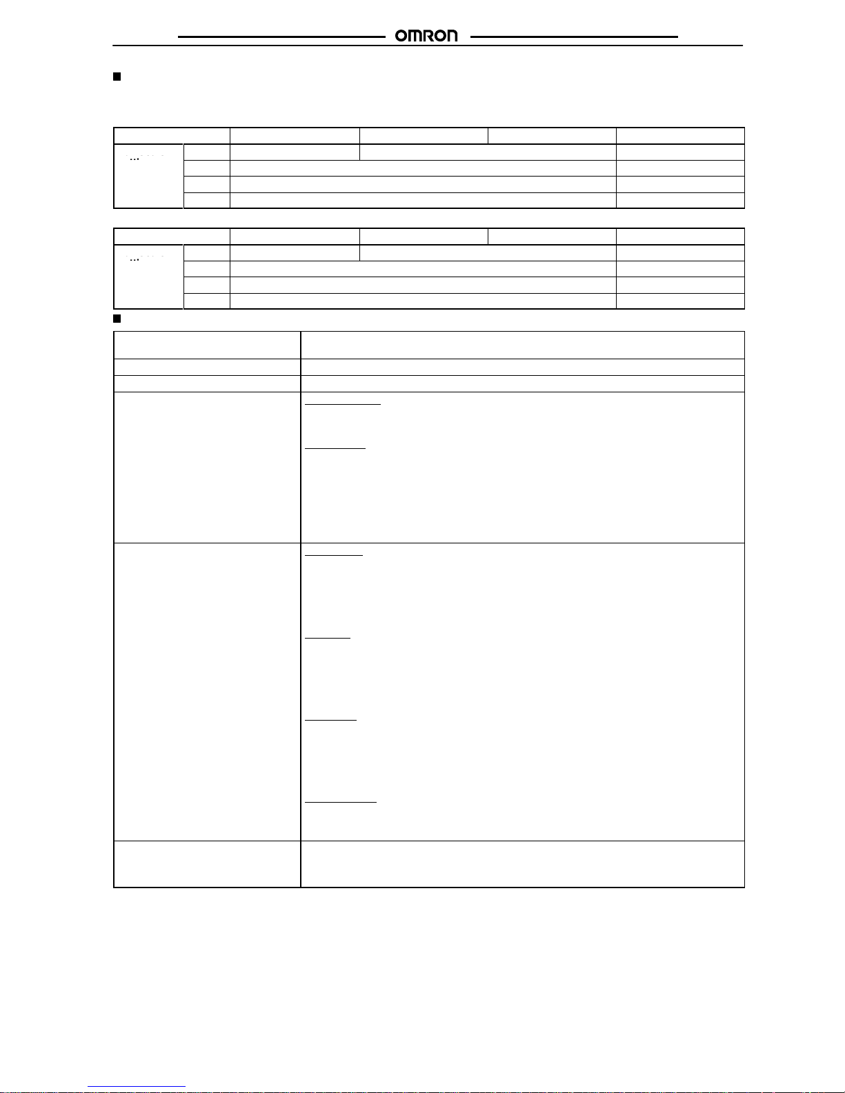
Specifications
General
Item H3CR-A/-AS H3CR-AP H3CR-A8/-A8S H3CR-A8E
Operating
mode
A: ON-delay
B: Flicker OFF start
B2: Flicker ON start
C:
Signal ON/OFF-delay
D:
Signal OFF-delay
E: Interval
G: Signal ON/OFF-delay (Only for H3CR-A-300)
J: One-shot (Only for H3CR-A-300)
A: ON-delay (power supply start)
B2: Flicker ON start (power supply start)
E:
Interval (power supply start)
J: One-shot (power supply start)
Pin type
11-pin 8-pin
Input type
No-voltage input
V
oltage input
---
T
ime-limit output
type
H3CR-A/-A8/-AP:
Relay output (DPDT)
H3CR-AS/-A8S: Transistor output (NPN/PNP universal)*
Relay output (SPDT)
Instantaneous output
type
---
Relay output (SPDT)
Mounting method
DIN track mounting, surface mounting, and flush mounting
Approved standards
UL508, CSA C22.2 No.14, NK, Lloyds
Conforms to EN61812-1 (VDE0435/P2021), IEC60664-1 (VDE01
10) 4kV/2, EN60947-5-1 (for contact output),
and EN60947-5-2 (for non-contact output).
*The internal circuits are optically isolated from the output. This enables universal application as NPN or PNP transistor
.
Page 5
H3CR-A
H3CR-A
7
Time Ranges
Note: When
the time setting knob is turned below “0” until the point where the time setting knob stops, the output will operate instantaneously
at
all time range settings.
Standard (0.05-s to 300-h) Models
Time
unit
s (sec)
min h (hrs)
x10 h (10 h)
Full scale
1.2
0.05 to 1.2 0.12 to 1.2 1.2 to 12
u sca e
setting
3
0.3 to 3 3 to 30
12
1.2 to 12 12 to 120
30
3 to 30 30 to 300
Double (0.1-s to 600-h) Models
Time
unit
s (sec)
min h (hrs)
x10 h (10 h)
Full scale
2.4
0.1 to 2.4 0.24 to 2.4 2.4 to 24
u sca e
setting
6
0.6 to 6 6 to 60
24
2.4 to 24 24 to 240
60
6 to 60 60 to 600
Ratings
Rated
supply voltage (see note 1)
100 to 240 V
AC (50/60 Hz)/100 to 125 VDC, 24 to 48 V
AC (50/60 Hz)/12 to 48 VDC (24 to
48 V
AC/VDC for H3CR-A8E) (see note 2)
Operating voltage range
85% to 1
10% of rated supply voltage (90% to 1
10% at 12 VDC)
Power reset
Minimum power-opening time: 0.1 s
Input
No-voltage Input
ON impedance:
1 kΩ
max.
ON residual voltage: 1 V max.
OFF impedance:
100 kΩ min.
V
oltage Input
Max. permissible capacitance between inputs lines (terminals 6 and 7): 1,200 pF
Load connectable in parallel with inputs (terminals 6 and 7).
• 100
to 240 V
AC/100 to 125 VDC
High (logic) level:
85 to 264 V
AC/85 to 137.5 VDC
Low (logic) level:
0 to 10 V
AC/0 to 10 VDC
•
24 to 48 V
AC/12 to 48 VDC
High (logic) level:
20.4 to 52.8 V
AC/10.8 to 52.8 VDC
Low (logic) level:
0 to 2.4 V
AC/0 to 1.2 VDC
Power consumption
H3CR-A/-A8
• 100
to 240 V
AC/100 to 125 VDC
(When at 240 V
AC, 60 Hz)
Relay ON: approx. 2.1 V
A (1.6 W)
Relay OFF: approx. 1.3 V
A (1.1 W)
•
24 to 48 V
AC/12 to 48 VDC
(When at 24 VDC)
Relay ON: approx. 0.8 W
Relay OFF: approx. 0.2 W
H3CR-AP
(see note 3)
• 100
to 240 V
AC/100 to 125 VDC
(When at 240 V
AC, 60 Hz)
Relay ON: approx. 2.5 V
A (2.2 W)
Relay OFF: approx. 1.8 V
A (1.7 W)
•
24 to 48 V
AC/12 to 48 VDC
(When at 24 VDC)
Relay ON: approx. 0.9 W
Relay OFF: approx. 0.3 W
H3CR-A8E
• 100
to 240 V
AC/100 to 125 VDC
(When at 240 V
AC, 60 Hz)
Relay ON/OFF: approx. 2 V
A (0.9 W)
•
24 to 48 V
AC/VDC
(When at 24 VDC)
Relay ON/OFF: approx. 0.9 W
H3CR-AS/-A8S
•
24 to 48 V
AC/12 to 48 VDC
(When at 24 VDC)
Output ON: 0.3 W Output OFF: 0.2 W
Control outputs T
ime limit contacts:
5 A at 250 V
AC/30 VDC, resistive load (cosφ
= 1)
T
ransistor output:
Open collector (NPN/PNP), 100 mA max. at 30 VDC max.,
residual voltage: 2 V max.
Instantaneous contact:
5 A at 250 V
AC, resistive load (cosφ
= 1)
Note: 1.
DC ripple rate: 20% max. if the power supply incorporates a single-phase, full-wave rectifier
.
2. Each
24-to-48-V
AC/12-to-48-VDC model causes an inrush current
of approximately 0.85 A. Pay careful attention when attempting
to
turn ON power to such a model with non-contact output from a device such as a sensor
.
3. The
values are for when the terminals 2 and 7 and terminals 10 and 6 are short-circuited, and include the consumption
current of the
input circuit.
Page 6

H3CR-A
H3CR-A
8
Characteristics
Accuracy
of
operating time
±
0.2% FS max. (
±0.2%±
10 ms max. in a range of 1.2 s)
Setting error ±
5% FS ±50 ms (see note)
Reset time
Min. power-opening time:
0.1 s max.
Min. pulse width:
0.05 s (H3CR-A/-AS)
Reset voltage
10% max. of rated voltage
Influence of voltage±0.2% FS max. (
±0.2%±
10 ms max. in a range of 1.2 s)
Influence of
temperature
±
1% FS max. (
±1%±
10 ms max. in a range of 1.2 s)
Insulation
resistance
100 MΩ min. (at 500 VDC)
Dielectric strength
2,000 V
AC (1,000 V
AC for H3CR-Aj
S), 50/60 Hz for 1 min (between current-carrying metal parts and
exposed non-current-carrying metal parts)
2,000 V
AC (1,000 V
AC for H3CR-Aj
S), 50/60 Hz for 1 min (between control output terminals and operating
circuit)
2,000 V
AC, 50/60 Hz for 1 min (between contacts of dif
ferent polarities)
1,000 V
AC, 50/60 Hz for 1 min (between contacts not located next to each other)
2,000 V
AC, 50/60 Hz for 1 min (between input and control output terminals and operation circuit)
Impulse withstand
voltage
3 kV (between power terminals) for 100 to 240 V
AC/100 to 125 VDC, 1 kV for 24 to 48 V
AC/12 to 48 VDC
4.5 kV (between current-carrying terminal and exposed non-current-carrying metal parts) for 100 to
240 V
AC/100 to 125 VDC, 1.5 kV for 24 to 48 V
AC/12 to 48 VDC and 24 to 48 V
AC/VDC
Noise immunity
±
1.5 kV (between power terminals) and ±600 V (between no-voltage input terminals), square-wave noise by
noise simulator (pulse width: 100 ns/1
µs, 1-ns rise)
Static immunity
Malfunction: 8 kV
Destruction: 15 kV
V
ibration resistance
Destruction:
10 to 55 Hz with 0.75-mm double amplitude each in 3 directions for 2 hours each
Malfunction:
10 to 55 Hz with 0.5-mm double amplitude each in 3 directions for 10 minutes each
Shock resistance
Destruction:
1,000 m/s2 3 times each in 6 directions
Malfunction:
100 m/s2 3 times each in 6 directions
Ambient
temperature
Operating: –10°
C to 55°C (with no icing)
Storage: –25°
C to 65°C (with no icing)
Ambient humidity
Operating:
35% to 85%
Life expectancy
Mechanical:
20,000,000 operations min. (under no load at 1,800 operations/h)
Electrical:
100,000 operations min. (5 A at 250 V
AC, resistive load at 1,800 operations/h)
EMC (EMI) EN50081-2
Emission Enclosure: EN55011 Group 1 class A
Emission AC Mains:
EN55011 Group 1 class A
(EMS) EN50082-2
Immunity ESD:
EN61000-4-2:
4 kV contact discharge (level 2)
8 kV air discharge (level 3)
Immunity RF-interference from AM Radio W
aves: ENV50140:
10 V/m (80 MHz to 1 GHz)
(level 3)
Immunity RF-interference from Pulse-modulated Radio W
aves: ENV50204:
10 V/m (900±5 MHz) (level 3)
Immunity Conducted Disturbance:
ENV50141:
10 V (0.15 to 80 MHz) (level 3)
Immunity Burst:
EN61000-4-4:
2 kV power-line (level 3)
2 kV I/O signal-line (level 4)
Immunity Surge:
EN61000-4-5:
1 kV line to line
2 kV line to ground (level 3)
Case color
Light gray (Munsell 5Y7/1)
Degree of protection
IP40 (panel surface)
Weight
Approx. 90 g
Note:
The value is ±5% FS +100 ms to –0 ms max. when the C, D, or G mode signal of the H3CR-AP is OFF
.
Page 7
H3CR-A
H3CR-A
9
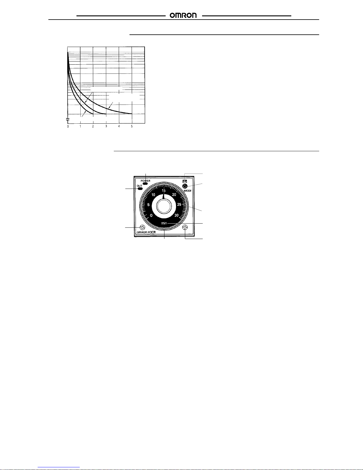
Engineering Data
Reference:A
maximum current of 0.15 A can be switched at 125 VDC (cosφ = 1)
and a maximum current of 0.1 A can be switched if L/R is 7 ms. In
both cases, a life of 100,000 operations can be expected.
The minimum applicable load is 10 mA (100 mA for H3CR-A8E) at
5 VDC (failure level: P).
Load current (A)
30 VDC L/R = 7 ms
250 VAC/30 VDC
(cosφ
= 1)
250 VAC (cosφ
= 0.4)
Switching operations (x 10 )
3
10,000
5,000
1,000
500
100
Nomenclature
Power
indicator (green) (Flashes when T
imer
operates; lit when T
imer stops operating)
Operating mode display window
Operating mode selector
Select a mode from:
A, B, B2, C, D, and E (H3CR-A, -AP
, and -AS)
A, B2, E and J (H3CR-A8, -A8S, and -A8E)
G and J (H3CR-A-300)
Scale range display windows
T
ime unit display window
T
ime unit selector (select one
from sec, min, hrs, and 10h)
T
ime setting
knob (set time)
Output indicator (orange)
(Lit when output)
T
ime range selector (select one
from 1.2, 3, 12, and 30 at full
scale; with the H3CR-Aj-301,
select from 2.4, 6, 24, or 60 at
full scale. )
Page 8
H3CR-A
H3CR-A
10
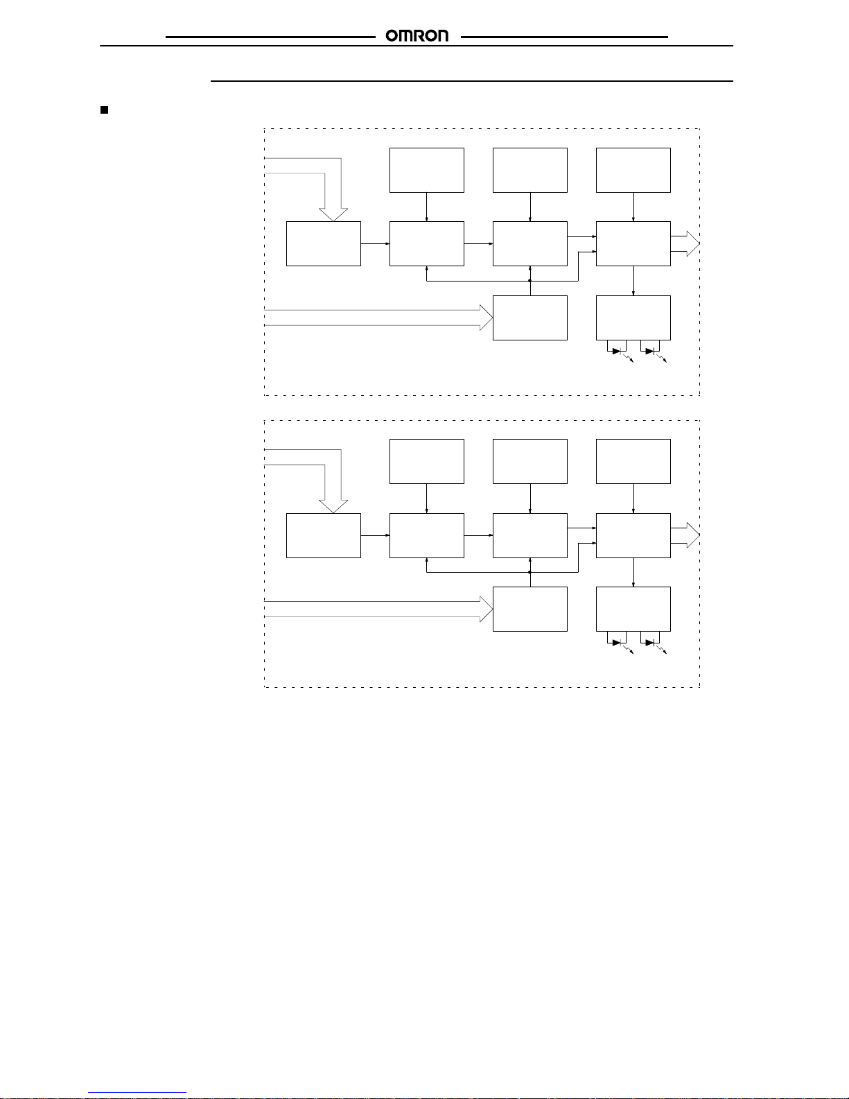
Operation
Block Diagrams
H3CR-A/AS
AC
(DC) input
Power supply
circuit
Zero setting
detection
circuit
Oscillation
circuit
T
ime range/
unit selectors
Counting
circuit
Operating
mode selector
Output circuit
Reset input, start input, and gate input
Input circuit
Indicator
circuit
Power-ON
indicator
Output-ON
indicator
H3CR-AP
AC (DC) input
Power supply
circuit
Zero setting
detection
circuit
Oscillation
circuit
T
ime range/
unit selectors
Counting
circuit
Operating
mode selector
Output circuit
Start
Input circuit
Indicator
circuit
Power-ON
indicator
Output-ON
indicator
Page 9
H3CR-A
H3CR-A
11
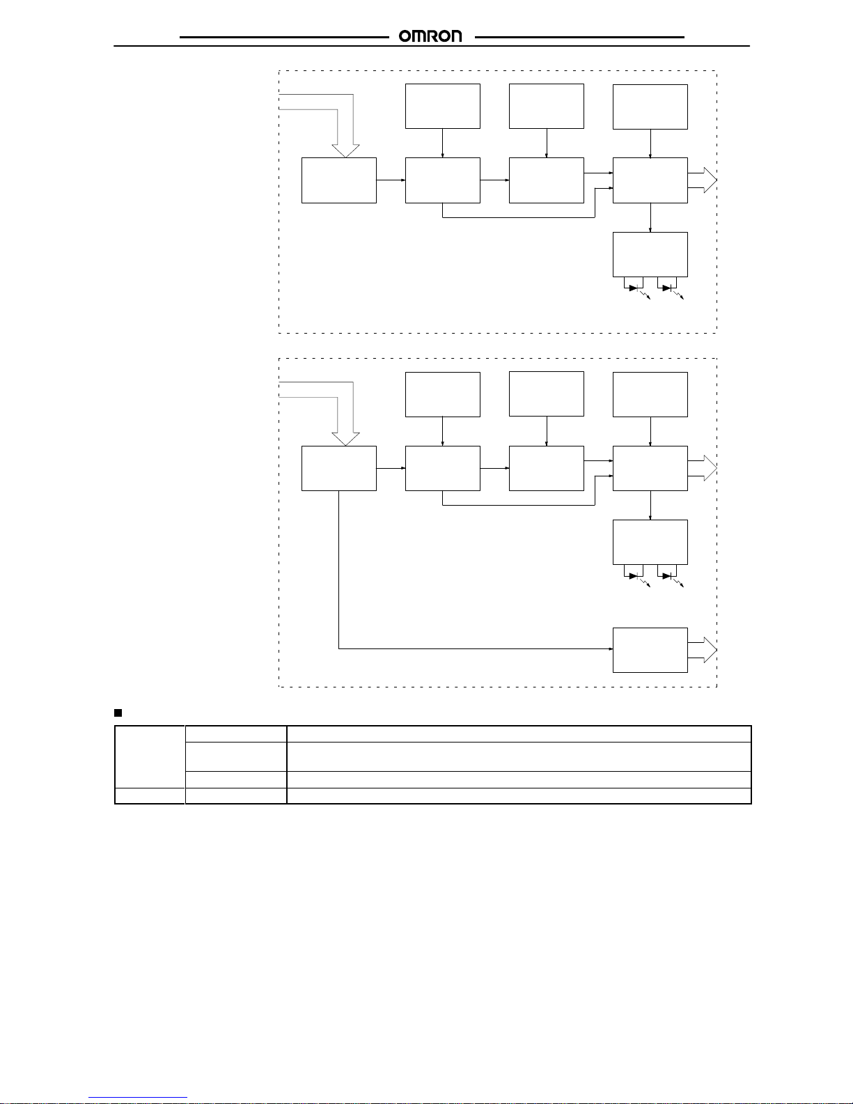
H3CR-A8/A8S
AC (DC) input
Power supply
circuit
Zero setting
detection
circuit
Oscillation
circuit
T
ime range/
unit selectors
Counting
circuit
Output circuit
Indicator
circuit
Power-ON
indicator
Output-ON
indicator
Operating
mode selector
H3CR-A8E
Instantaneous
output circuit
AC (DC) input
Power supply
circuit
Zero setting
detection
circuit
Oscillation
circuit
T
ime range/
unit selectors
Counting
circuit
Output circuit
Indicator
circuit
Power-ON
indicator
Output-ON
indicator
Operating
mode selector
I/O Functions
Inputs Start Starts
time-measurement.
(for -A/-AS
models)
Reset
Interrupts time-measurement and resets time-measurement value. No time-measurement is made
and control output is OFF while the reset input is ON.
Gate
Prohibits time-measurement.
Outputs Control output
Outputs are turned ON according to designated output mode when preset value is reached.
Note:
H3CR-AP incorporates start input only
.
Page 10
H3CR-A
H3CR-A
12
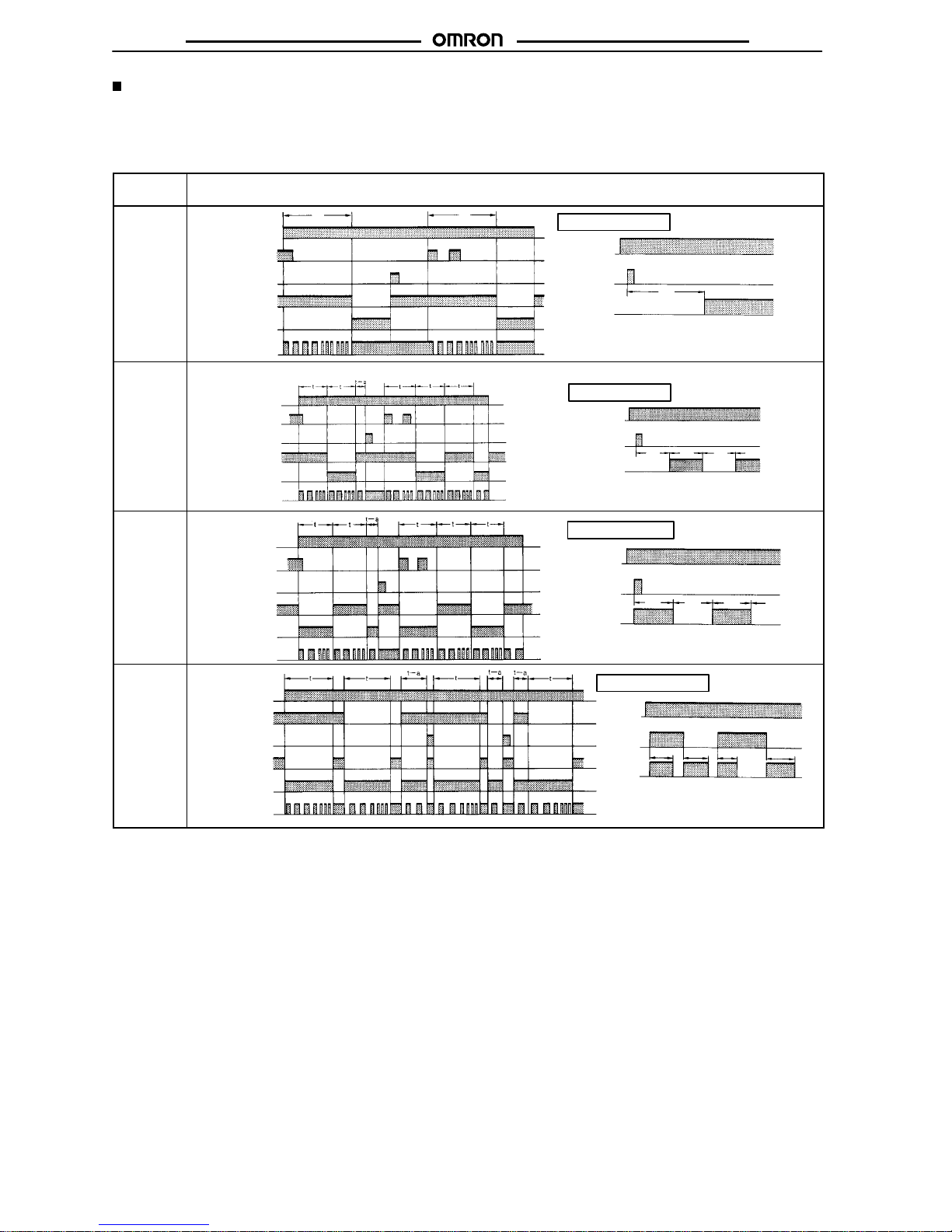
Timing Chart
Note: 1. The
minimum power-opening time (“Rt”) is 0.1 s and the minimum pulse width is 0.05 s.
2.
The letter “t” in the timing charts stands for the set time and “t–a” means that the period is less than the time set.
H3CR-A/-AS/-AP*
*H3CR-AP model incorporates start input only
.
Operating
mode
T
iming chart
A:
ON-delay
Power
Output
t
Basic operation
Power
Start
Reset
Output relay (NC)
Output relay (NO)
(Output indicator)
Power indicator
t t
Note: Start
input is invalid
while the T
im-
er
is in operation.
Start
(see note)
B:
Flicker OFF
start
Power
Output relay (NO)
(Output indicator)
Power indicator
Start
Reset
Output relay (NC)
Basic
operation
Power
Output
t t t t
Note: Start input is invalid while
the
T
imer is in operation.
Start
(see note)
B2:
Flicker ON
start
Basic operation
Power
Output
t
t
t t
Power
Start
Reset
Output relay (NO)
(Output indicator)
Power indicator
Output relay (NC)
Note: Start
input is invalid
while the T
im-
er
is in operation.
Start
(see note)
C:
Signal
ON/OFFdelay
Basic
operation
Power
Output
tt
t
t
Power
Start
Reset
Output relay (NC)
Power indicator
Output relay (NO)
(Output indicator)
Note: Start input is valid and re-
triggerable
while the T
imer
is
in
operation.
Start
(see note)
Page 11
H3CR-A
H3CR-A
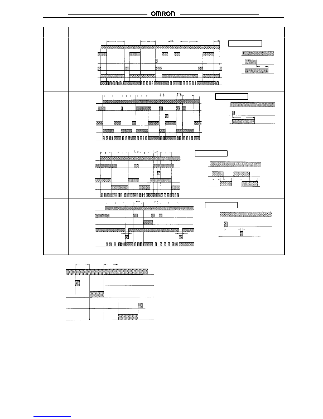
13
Operating
mode
Timing
chart
D:
Signal
OFF-delay
Basic operation
Power
Output
t
Output relay (NC)
Power indicator
Power
Start
Reset
Output relay (NO)
(Output indicator)
Note: Start input is valid and
re-triggerable
while the
Timer
is in operation.
Start
(see note)
E:
Interval
Power
Output
t
Basic operation
Power
Start
Reset
Output relay (NC)
Power indicator
Output relay (NO)
(Output indicator)
Note: Start input is valid and
re-triggerable while
the Timer is in operation.
Start
(see note)
G:
Signal
ON/OFFdelay
Basic
operation
Power
Start
Reset
Output relay (NC)
Power indicator
Power
Output
t
t
Output relay (NO)
(Output indicator)
Note: Start input is valid and re-trigger-
able
while
the T
imer is in operation.
t
t
Start
(see note)
J:
One-shot
output
Basic
operation
Power
Start
Reset
Output relay (NC)
Power indicator
1±0.6 s
(Fixed)
1±0.6 s
(Fixed)
Output
Power
Output relay (NO)
(Output indicator)
1±0.6 s
(Fixed)
Note: Start input is valid and re-
triggerable while the Timer
is
in operation.
Start
(see note)
t
Gate
Signal Input
Power
Start
Gate
Reset
Output
relay
ON
OFF
ON
OFF
ON
OFF
ON
OFF
ON
OFF
Note: 1. This
timing chart indicates
the gate input in op
-
erating
mode A (ON-delay operation).
2.
The set time is the sum of t1 and t2.
3.
H3CR-AP model incorporates start input only
.
t
1
t
2
Page 12

H3CR-A
H3CR-A
14
H3CR-A8/-A8S
Operating
mode
T
iming chart
A:
ON-delay
Power
Output
t
Basic operation
Power
Output relay
(NC)
Output relay
(NO) (output
indicator)
Power
indicator
B2:
Flicker ON
start
Power
Output relay
(NC)
Output relay
(NO) (output
indicator)
Power
indicator
Power
Output
t
Basic
operation
t t t
E:
Interval
Power
Output
t
Basic operation
Power
Output relay
(NC)
Power
indicator
Output relay
(NO) (output
indicator)
J:
One-shot
output
Power
Output relay
(NC)
Output relay
(NO) (output
indicator)
Power
indicator
Power
Output
t
Basic
operation
1±0.6
s
(Fixed)
1±0.6 s
(Fixed)
1±0.6 s
(Fixed)
Page 13
H3CR-A
H3CR-A
15
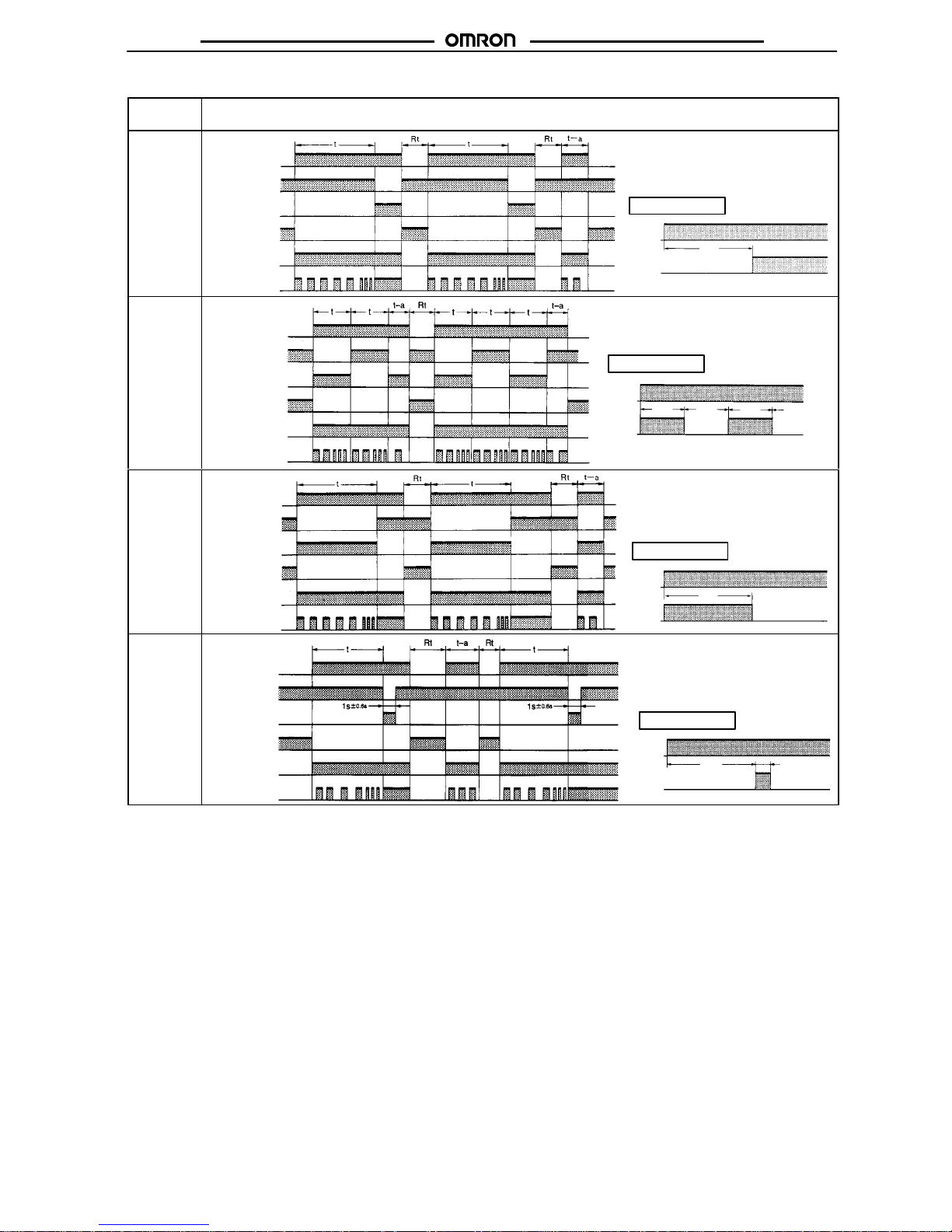
H3CR-A8E
Operating
mode
Timing
chart
A:
ON-delay
Power
Output
t
Basic operation
Power
Output relay
(NC)
Power indicator
Instantaneous
output relay (NC)
Instantaneous
output relay (NO)
Output relay
(NO) (output
indicator)
B2:
Flicker ON
start
Power
Output relay
(NC)
Power indicator
Instantaneous
output relay (NC)
Instantaneous
output relay (NO)
Output relay
(NO) (output
indicator)
Power
Output
t
Basic
operation
ttt
E:
Interval
Power
Output relay
(NC)
Power indicator
Instantaneous
output relay (NC)
Instantaneous
output relay (NO)
Output relay
(NO) (output
indicator)
Power
Output
t
Basic
operation
J:
One-shot
output
Power
Output relay
(NC)
Power indicator
Instantaneous
output relay (NC)
Instantaneous
output relay (NO)
Output relay
(NO) (output
indicator)
Power
Output
t
Basic
operation
1±0.6
s
(Fixed)
(Fixed) (Fixed)
Page 14
H3CR-A
H3CR-A
16
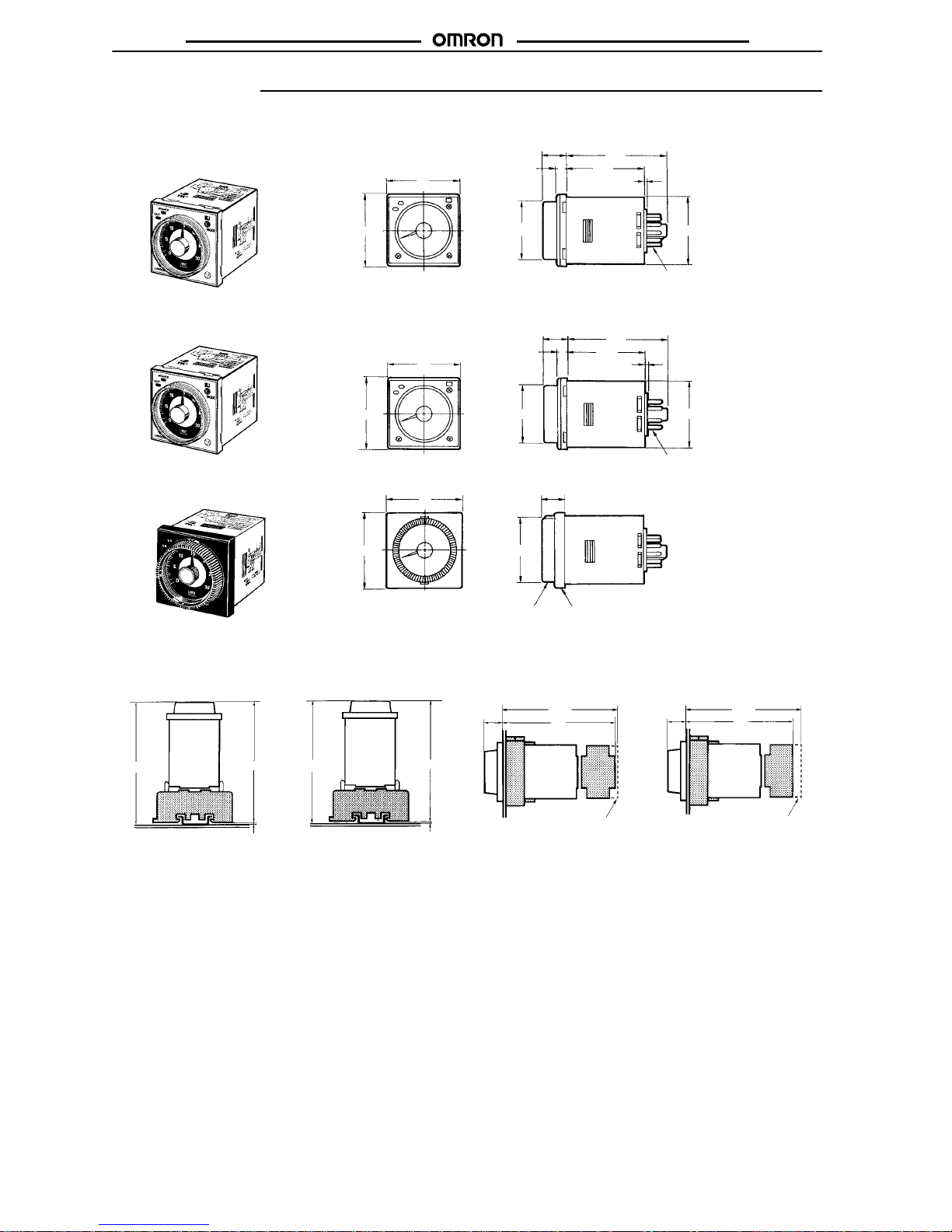
Dimensions
Note: All
units are in millimeters unless otherwise indicated.
H3CR-A
H3CR-AP
H3CR-AS
H3CR-A8
H3CR-A8S
H3CR-A8E
11 pins
48
48
66.6
52.3
15
6
39 dia. 44.8 x 44.8
0.7
8 pins
48
66.6
48
15
6
52.3
0.7
39 dia.
44.8 x 44.8
Dimensions with Set Ring
Time Setting
Ring
Panel cover
50
16.5
50
42 dia.
Dimensions with Front Connecting Socket
P2CF-08-j/P2CF-11-j
*These
dimensions vary with the kind of DIN track (reference value).
100.8*
98.5
2.3
*
H3CR-A
H3CR-AS
H3CR-A8j
P2CF-11
P2CF-08
89.9*
87.6
2.3
*
H3CR-A
H3CR-AS
+
Adapter
H3CR-A8j
+
Adapter
Y92F-30
P3GA-11
Y92F-30
P3G-08
80
15
15
Dimensions with Back Connecting Socket
P3G-08/P3GA-11
75
P2CF-11-E P2CF-08-E
81.5 81.5
(When
Y92A-48G
mounted)
(When
Y92A-48G
mounted)
Page 15
H3CR-A
H3CR-A
17
Installation
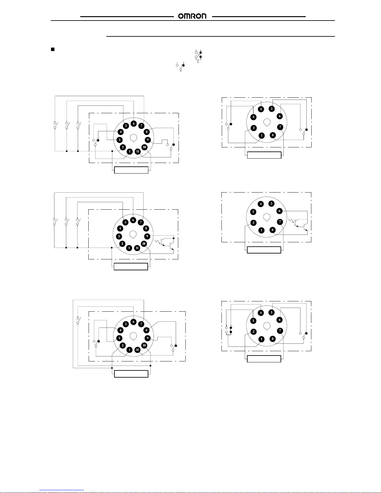
Terminal Arrangement
Note: The
delayed contact of conventional T
imers was indicated as
The contact symbol of the H3CR-A is indicated as because its operating mode is six multi-modes (four multi-modes for the
H3CR-A8).
11-pin Models
H3CR-A (Contact Output)
Reset input
Start input
Gate input
(–)(~) (+)(~)
Power supply
H3CR-AS (Transistor Output)
Power supply
(–)(~) (+)(~)
Reset input
Start input
Gate input
Note: Terminals
1, 3, 4, and 8 are
empty
. T
erminals 2, 5, 6, 7, and
10
are the same as for the H3CR-A.
H3CR-AP (Contact Output)
Power supply
(–)(~) (+)(~)
Start input
Note: T
erminal 5 is empty
.
8-pin Models
H3CR-A8 (Contact Output)
(–)
(~)
(+)
(~)
Power supply
H3CR-A8S (Transistor Output)
(–)
(~)
Power supply
(+)
(~)
Note: Terminals
1, 3, 4, and 5 are empty
. T
erminals 2 and 7 are the
same
as for the H3CR-A8.
H3CR-A8E (Contact Output)
(–)
(~)
(+)
(~)
Power supply
Page 16
H3CR-A
H3CR-A
18
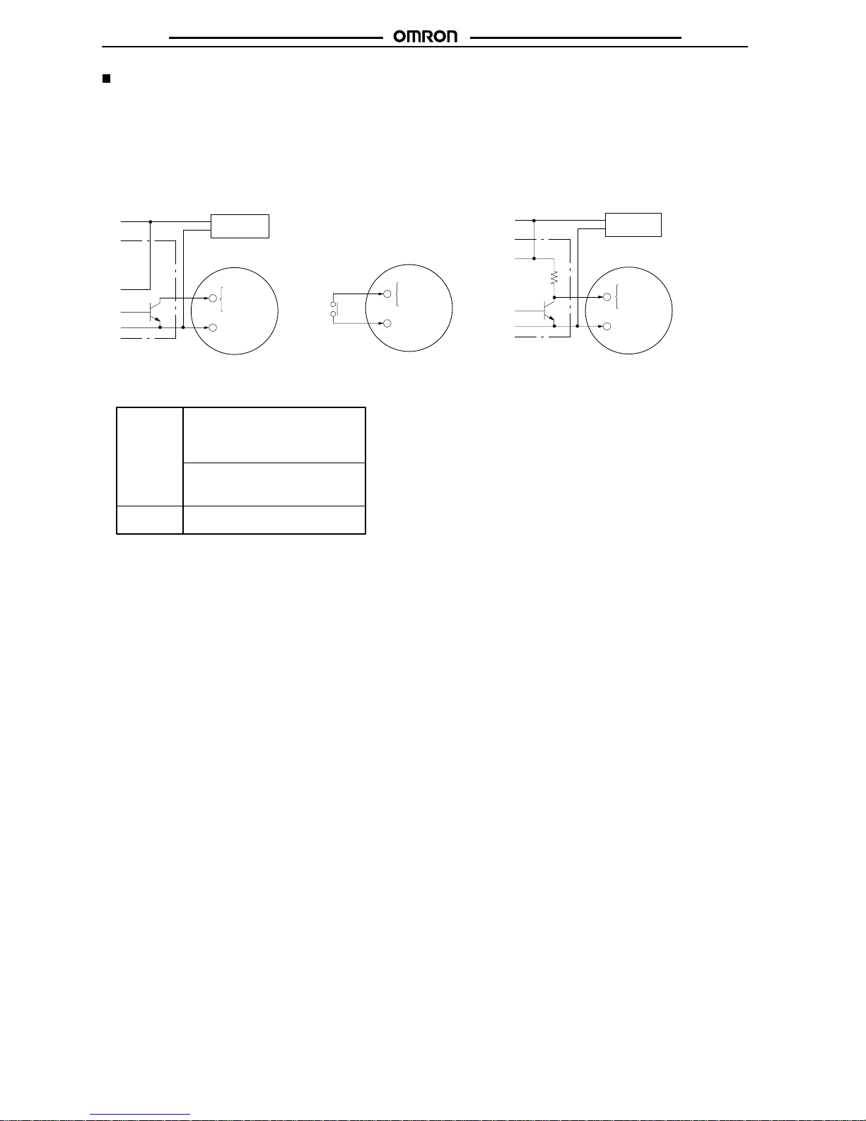
Input Connections
H3CR-A/-AS
The
inputs of the H3CR-A/-AS are no-voltage (short-circuit or open) inputs.
No-voltage Input Signal Levels
No-contact
input
Contact
input
1. Short-circuit level
Transistor ON
Residual voltage: 1 V max.
Impedance when ON: 1 kΩ max.
2. Open level
Transistor OFF
Impedance when OFF: 100 kΩ min.
Use contacts which can adequate
-
ly switch 0.1 mA at 5 V
No-contact Input
(Connection to NPN open
collector output sensor
.)
Contact Input
No-contact Input
(Connection to a voltage
output sensor
.)
No-voltage Inputs
12 to 24 VDC
(sensor power supply)
Sensor
Timer
5 Gate
6 Start
7 Reset
2 Input (0 V)
Operates with transistor ON
+–DC power
supply
Timer
Operates with relay ON
12 to 24 VDC
(sensor power supply)
Sensor
Timer
Operates with transistor ON
+–DC power
supply
5 Gate
6 Start
7 Reset
2 Input (0 V)
5 Gate
6 Start
7 Reset
2 Input (0 V)
Page 17
H3CR-A
H3CR-A
19
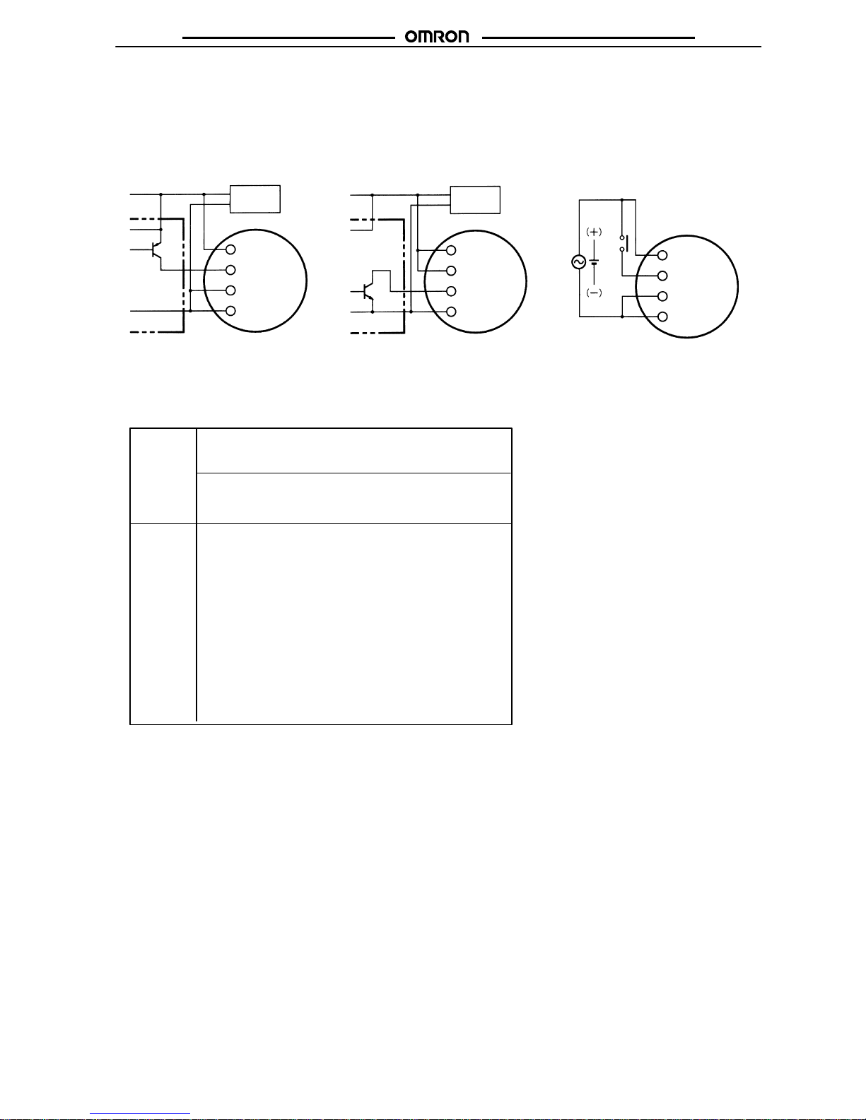
H3CR-AP
The
start input of the H3CR-AP is voltage input. (V
oltage imposition or open)
V
oltage Input Signal Levels
No-contact
input
Contact
input
1. T
ransistor ON
Residual voltage: 1 V max.
The voltage between terminals 6 and 7 must be 10.8 VDC min.
2. T
ransistor OFF
Leakage current: 0.01 mA max.
The voltage between terminals 6 and 7 must be 1.2 VDC max.
Use contacts that can adequately switch 0.1 mA at each oper
ating voltage.
The voltage between terminals 6 and 7 with contacts ON or
OFF must satisfy the specified value.
Contacts ON
100-to-240-V
AC and 100-to-125-VDC models: 85 to 264 V
AC
or 85 to 137.5 VDC
24-to-48-V
AC and 12-to-48-VDC models: 20.4 to 52.8 V
AC or
10.8 to 52.8 VDC
Contacts OFF
100-to-240-V
AC and 100-to-125-VDC models: 0 to 10 V
AC or
0 to 10 VDC
24-to-48-V
AC and 12-to-48-VDC models: 0 to 2.4 V
AC or 0 to
1.2 VDC
No-contact Input
(Connection to PNP open
collector output sensor)
No-contact Input
(Connection to NPN open
collector output sensor)
Contact Input
12 to 24 VDC
(sensor power supply)
Sensor
Timer
6 Start
Operates with PNP transistor ON
Operates with NPN transistor ON
12 to 24 VDC
(sensor power supply)
Timer
Sensor
Timer
Operates with relay ON
Note: Refer to the signal levels in the fol-
lowing table and be aware of the
minimum
applicable load of the relay
.
Voltage Inputs
10 Power
supply (+)
7 Input 0V
6 Start
10 Power
supply (+)
7 Input 0V
2 Power
supply
(–)
2 Power
supply
(–)
AC power supply
DC power supply
6 Start
10 Power
supply (+)
7 Input 0V
2 Power
supply
(–)
+
–
DC
power
supply
+
–
DC power
supply
Note: The input circuit is isolated from the
power supply circuit. Thus, an NPN
transistor
can be connected.
Page 18

H3CR-A
H3CR-A
20
Application Examples
A Mode: ON-delay
ON-delay
operation (A mode) is a basic mode.
1. Power-ON Start/Power-OFF Reset
The
Power-ON start/Power-OFF reset operation is
a standard oper
-
ating
method.
Power (2 and 10)
Start (2 and 6)
Control output: NC (8 and 11)
NC (1 and 4)
Control output:NO (9 and 11)
NO (1 and 3)
Power indicator
Flashing Lit
t
Externally short-circuited
Power
supply
2.
Signal Start/Signal Reset
The
Signal start/Signal reset
operation is useful for remote control of
the Timer.
Power (2 and 10)
Start (2 and 6)
Control output: NC (8 and 11)
NC (1 and 4)
Control output: NO (9 and 11)
NO (1 and 3)
Power indicator
Flashing
Lit
Reset (2 and 7)
Lit
(Power continuously supplied)
Start signal (remote control possible)
Reset signal
(remote control possible)
Power
supply
3.
Control of Integrated T
ime with Gate Signal
With a gate signal, the Power-ON start operation and Signal start
operation
can be controlled (the operation can be interrupted).
Power (2 and 10)
Start (2 and 6)
Control output: NC (8 and 11)
NC (1 and 4)
Control output: NO (9 and 11)
NO (1 and 3)
Power indicator
Power
supply
Flashing Lit
Gate (2 and 5)
Gate signal (The operation is interrupted with the
gate signal if the Timer detects an abnormal signal.)
Externally
short-circuited
t
1
t
2
t1 + t2: set time
B/B2 Mode: Flicker
The flicker operation in the B and B2 modes can be effectively
applied
to lamp or
buzzer (ON and OFF) alarms or the monitoring of
an
intermittent operation with a display
.
1. Power-ON Start/Power-OFF Reset (in B Mode)
Power (2 and 10)
Start (2 and 6)
Control output: NC (8 and 11)
NC (1 and 4)
Control output: NO (9 and 11)
NO (1 and 3)
Power indicator
Flashing
Externally short-circuited
Power
supply
Page 19

H3CR-A
H3CR-A
21
2.
Signal Start/Signal Reset (in B Mode)
If there is an abnormal signal, flashing starts. When the abnormal
condition
is restored, a reset signal stops the display flashing.
Power (2 and 10)
Start (2 and 6)
Control output: NC (8 and 11)
NC (1 and 4)
Control output: NO (9 and 11)
NO (1 and 3)
Power indicator
Reset (2 and 7)
Lit Flashing Lit
(Power continuously supplied)
Start signal
Reset signal
Power
supply
C Mode: Signal ON/OFF-delay
The
Signal ON-/OFF-delay operation (C mode) is useful for the
con
-
trol
of distribution of products on a production line into boxes by the
specified
number or time.
1. Power-ON Start/Instantaneous Operation/T
ime-limit Reset
A
set of these functions is useful for the operation of a machine for a
specified
period when power is ON.
Power (2 and 10)
Start (2 and 6)
Control output: NC (8 and 11)
NC (1 and 4)
Control output: NO (9 and 11)
NO (1 and 3)
Externally short-circuited
Power
supply
2.
Signal-ON-OFF Start/Instantaneous Operation/T
ime-limit
Reset
Power (2 and 10)
Start (2 and 6)
Control output: NC (8 and 11)
NC (1 and 4)
Control output: NO (9 and 11)
NO (1 and 3)
Power indicator
Flashing
Flashing
Flashing
Lit
Start signal
(The operation starts with the signal ON or OFF)
Lit
Lit
Lit
(Power continuously supplied)
Power
supply
D Mode: Signal OFF-delay
Signal OFF-delay operation (D mode) can be effectively used to
keep
a load operating for a certain period. For example, this function
enables
the cooling
fan for a lamp or heater to operate for a certain
period
after the lamp or heater is switched OFF
.
1. Power-ON Start/Instantaneous Operation/T
ime-limit Reset
Power (2 and 10)
Start (2 and 6)
Control output: NC (8 and 11)
NC (1 and 4)
Control output: NO (9 and 11)
NO (1 and 3)
Power indicator
Lit Flashing
Start signal (NC to NO)
Power
supply
Lit
Page 20

H3CR-A
H3CR-A
22
2.
Signal Start/Instantaneous Operation/T
ime-limit Reset
Lit
Start signal (NO to NC to NO)
Power (2 and 10)
Start (2 and 6)
Control output: NC (8 and 11)
NC (1 and 4)
Control output: NO (9 and 11)
NO (1 and 3)
Power indicator
Flashing Lit
(Power continuously supplied)
Power
supply
E Mode: Interval
1. Power-ON Start/Instantaneous Operation/T
ime-limit Reset
This
function is useful for the operation of a machine for a specified
period
after power is ON.
Power (2 and 10)
Start (2 and 6)
Control output: NC (8 and 11)
NC (1 and 4)
Control output: NO (9 and 11)
NO (1 and 3)
Power
supply
Externally short-circuited
2.
Signal Start/Instantaneous Operation/T
ime-limit Reset
This
function is useful for the repetitive control such as the filling of
liquid
for a specified period after each Signal start input.
Start signal
(Power continuously supplied)
Power
supply
Power (2 and 10)
Start (2 and 6)
Control output: NC (8 and 11)
NC (1 and 4)
Control output: NO (9 and 11)
NO (1 and 3)
t t
Page 21

H3CR-F
H3CR-F
23
Solid-state Twin Timers H3CR-F
DIN 48 x 48-mm Twin Timers
Wide
power supply ranges of 100 to 240 VAC and
48 to 125 VDC respectively.
Independent ON- and OFF-time settings. Further-
more, combinations of long ON- or OFF-time and
short OFF- or ON-time settings are possible.
Fourteen time ranges from 0.05 s to 30 h or from
1.2 s
to 300 h
depending on the model to be used.
Models with a flicker ON start or flicker OFF start
are available.
Easy sequence checks through instantaneous
outputs for a zero set value at any time range.
Length, when panel-mounted with a Socket, of 80
mm or less.
11-pin and 8-pin models are available.
RC
Ordering Information
Operating
Supply
voltage
0.05 s to 30 h models 1.2 s to 300 h models
Ope a g
modes
1
1-pin models 8-pin models
1
1-pin models 8-pin models
Flicker OFF start
100 to 240 V
AC H3CR-F H3CR-F8 H3CR-F-300 H3CR-F8-300
24 V
AC/DC
12 VDC
48 to 125 VDC
Flicker ON start
100 to 240 V
AC H3CR-FN H3CR-F8N H3CR-FN-300 H3CR-F8N-300
24 V
AC/DC
12 VDC
48 to 125 VDC
Note:
Specify both the model number and supply voltage when ordering.
Example: H3CR-F 24 V
AC/DC
Supply voltage
Model Number Legend:
H3CR - -
1 23 4
1.
Classification
F: T
win timers
2. Configuration
None: 11-pin socket
8: 8-pin socket
3. T
win T
imer Mode
None: Flicker OFF start
N: Flicker ON start
4. T
ime Range
None:
0.05 s to 30 h models
300:
1.2 s to 300 h models
Page 22

H3CR-F
H3CR-F
24
Accessories (Order Separately)
Name/specifications Models
Flush
Mounting Adapter
Y92F-30
us ou g dap e
Y92F-73
Y92F-74
Mounting T
rack
50 cm (l) x 7.3 mm (t)
PFP-50N
1 m (l) x 7.3 mm (t)
PFP-100N
1 m (l) x 16 mm (t)
PFP-100N2
End Plate
PFP-M
Spacer PFP-S
Protective Cover
Y92A-48B
T
rack Mounting/
8-pin P2CF-08
ac ou g/
Front Connecting Socket
8-pin, finger safe type
P2CF-08-E
11-pin P2CF-11
1
1-pin, finger safe type
P2CF-11-E
Back Connecting Socket
8-pin P3G-08
ac Co ec g Soc e
8-pin, finger safe type
P3G-08 with Y92A-48G (see note 1)
11-pin P3GA-11
1
1-pin, finger safe type
P3GA-1
1 with Y92A-48G (see note 1)
Hold-down Clip (see note 2)
For PL08 and PL1
1 Sockets
Y92H-7
For PF085A Socket
Y92H-8
Note: 1.
Y92A-48G is a finger safe terminal cover which is attached to the P3G-08 or P3GA-1
1 Socket.
2.
Hold-down Clips are sold in sets of two.
Specifications
General
Item H3CR-F H3CR-F8 H3CR-FN H3CR-F8N
Operating
mode
Flicker OFF start Flicker ON start
Pin type
11-pin 8-pin 11-pin 8-pin
Operating/Reset methodTime-limit operation/T
ime-limit reset or self-reset
Output type
Relay output (DPDT)
Mounting method
DIN track mounting, surface mounting, and flush mounting
Approved standards
UL508, CSA C22.2 No.14, NK, Lloyds
Conforms to EN61812-1 (VDE0435/P2021), IEC60664-1 (VDE0110) 4kV/2,
and EN60947-5-1 (for contact output).
Time Ranges
0.05
s to 30 h Models
T
ime unit
s (sec)
x10 s (10 s)
min h (hrs)
Setting 1.2
0.05 to 1.2 1.2 to 12 0.12 to 1.2
3
0.3 to 3 3 to 30 0.3 to 3
12
1.2 to 12 12 to 120 1.2 to 12
30
3 to 30 30 to 300 3 to 30
Note:
Instantaneous output is available at any time range. T
o obtain instantaneous output, set to below 0.
1.2 s to 300 h Models
T
ime unit
x10 s (10 s)
x10 min (10 min)
h (hrs)
x10 h (10 h)
Setting 1.2
1.2 to 12 1.2 to 12 0.12 to 1.2 1.2 to 12
3
3 to 30 3 to 30 0.3 to 3 3 to 30
12
12 to 120 12 to 120 1.2 to 12 12 to 120
30
30 to 300 30 to 300 3 to 30 30 to 300
Note:
Instantaneous output is available at any time range. T
o obtain instantaneous output, set to below 0.
Page 23

H3CR-F
H3CR-F
25
Ratings
Rated
supply voltage (see note)
100 to 240 V
AC (50/60 Hz),12 VDC, 24 VAC/DC (50/60 Hz), 48 to 125 VDC
Operating voltage range
85% to 1
10% of rated supply voltage; 90% to 1
10% with 12-VDC models
Power reset
Minimum power-opening time: 0.1 s
Power consumption
100 to 240 V
AC:
approx. 10 V
A (2.1 W) at 240 V
AC
24 V
AC/VDC:
approx. 2 V
A (1.7 W) at 24 V
AC
approx. 1 W at 24 VDC
48 to 125 VDC:
approx. 1.5 W at 125 VDC
12 VDC:
approx. 1 W at 12 VDC
Control outputs
Contact output: 5 A at 250 V
AC/30 VDC, resistive load (cosφ
= 1)
Note: A
power supply with a ripple of 20% max. (single-phase power supply with full-wave rectification) can be used with each DC Model.
Characteristics
Accuracy
of operating
time
±
0.2% FS max. (±0.2% FS ±10 ms max. in ranges of 1.2 and 3 s)
Setting error ±
5% FS ±50 ms max.
Reset time
0.1 s max.
Reset voltage
10 % max. of rated voltage
Influence of voltage
±
0.2% FS max. (±0.2% FS ±10 ms max. in ranges of 1.2 and 3 s)
Influence of
temperature
±
1% FS max. (±1% FS ±10 ms max. in ranges of 1.2 and 3s)
Insulation resistance
100 MΩ min. (at 500 VDC)
Dielectric strength
2,000 V
AC, 50/60 Hz for 1 min (between current-carrying metal parts and exposed non-current-carrying
metal parts)
2,000 V
AC, 50/60 Hz for 1 min (between control output terminals and operating circuit)
2,000 V
AC, 50/60 Hz for 1 min (between contacts of dif
ferent polarities)
1,000 V
AC, 50/60 Hz for 1 min (between contacts not located next to each other)
Impulse withstand
voltage
3 kV (between power terminals) for 100 to 240 V
AC, 48 to 125 VDC
1 kV for 12 VDC, 24 V
AC/DC
4.5 kV (between current-carrying terminal and exposed non-current-carrying metal parts) for 100 to 240 V
AC,
48 to 125 VDC
1.5 kV for 12 VDC, 24 V
AC/DC
Noise immunity
±
1.5 kV (between power terminals), square-wave noise by noise simulator (pulse width: 100 ns/1
µs, 1-ns
rise)
±
400 V for 12 VDC
Static immunity
Malfunction:8 kV
Destruction:15 kV
V
ibration resistance
Destruction:
10 to 55 Hz with 0.75-mm single amplitude for 2 hrs each in three directions
Malfunction:
10 to 55 Hz with 0.5-mm single amplitude for 10 min each in three directions
Shock resistance
Destruction:
980 m/s2 three times each in six directions
Malfunction:
98 m/s2 three times each in six directions
Ambient temperature
Operating:–10°
C to 55°C (with no icing)
Storage: –25°
C to 65°C (with no icing)
Ambient humidity
Operating: 35% to 85%
Life expectancy
Mechanical:
20 million operations min. (under no load at 1,800 operations/h)
Electrical:
100,000 operations min. (5 A at 250 V
AC, resistive load at 1,800 operations/h)
EMC (EMI) EN50081-2
Emission Enclosure: EN55011 Group 1 class A
Emission AC Mains:
EN55011 Group 1 class A
(EMS) EN50082-2
Immunity ESD:
EN61000-4-2:
4 kV contact discharge (level 2)
8 kV air discharge (level 3)
Immunity RF-interference from AM Radio W
aves: ENV50140:
10 V/m (80 MHz to 1 GHz)
(level 3)
Immunity RF-interference from Pulse-modulated Radio W
aves: ENV50204:
10 V/m (900±5 MHz) (level 3)
Immunity Conducted Disturbance:
ENV50141:
10 V (0.15 to 80 MHz) (level 3)
Immunity Burst:
EN61000-4-4:
2 kV power-line (level 3)
2 kV I/O signal-line (level 4)
Immunity Surge:
EN61000-4-5:
1 kV line to line (level 3)
2 kV line to ground (level 3)
Case color
Light Gray (Munsell 5Y7/1)
Enclosure ratings
IP40 (panel surface)
Weight
Approx. 100 g
Page 24

H3CR-F
H3CR-F
26
Engineering Data
Reference:
A maximum current of 0.15 A can be switched at 125 VDC (cosf = 1)
and a maximum current of 0.1 A can be switched if L/R is 7 ms. In
both cases, a life of 100,000 operations can be expected.
The minimum applicable load is 10 mA at 5 VDC (failure level: P).
Load current (A)
30 VDC L/R = 7 ms
250 VAC/30 VDC
(cosf
= 1)
250 VAC (cosf
= 0.4)
Switching operations (x 10 )
3
10,000
5,000
1,000
500
100
Nomenclature
ON indicator (orange)
Lit when the output is ON.
OFF indicator (green)
Lit
when the output is OFF
.
Scale range display
windows
Time range selector (select one
from 1.2, 3, 12, and 30 at full
scale)
For
both
ON-time and OFF-time.
OFF-time unit display window
OFF-time unit selector (select one from sec.
10
s, min., and hrs, or from 10 s, 10 min, hrs,
and 10 h)
ON-time
setting knob (with orange pointer)
For ON-time setting
OFF-time
setting knob (with green pointer)
For OFF-time setting
ON-time unit display window
ON-time unit selector (select one
from
sec. 10 s, min., and hrs, or from
10 s, 10 min, hrs, and 10 h)
Operation
Block Diagrams
ON indicator OFF indicator
Indicator
circuit
Power supply
circuit
One-chip microcomputer
Zero setting
detection
circuit
Time range/unit
selectors
ROM
RAM
Clock
AC
(DC) input
Output
circuit
I/O Functions
Inputs --Outputs Control output
Outputs are turned ON/OFF according to the time set by the ON- and OFF-time setting knob.
Page 25

H3CR-F
H3CR-F
27
Timing Chart
tON:ON
set time
t
OFF
:
OFF set time
Operating mode
T
iming chart
Flicker OFF start
ON
OFF
Power
ON
indicator
Output
NO
OFF
indicator
t
OFF
t
ON
t
OFFtON
t
OFF
t
OFF
0.1 s min.
Lit
Not lit
Lit
Not lit
Output
NC
ON
OFF
ON
OFF
Flicker ON start
t
ON
Power
ON
OFF
ON
indicator
OFF
indicator
t
OFF
t
ON
t
OFF
t
ON
t
OFF
0.1 s min.
Lit
Not lit
Lit
Not lit
Output
NO
Output
NC
ON
OFF
ON
OFF
Note: 1. The
reset time requires a minimum of 0.1 s.
2. When
power is supplied in flicker ON start mode, the OFF indicator lights momentarily
. This, however
, has no ef
fect on the perfor
-
mance
of the T
imer.
Page 26

H3CR-F
H3CR-F
28
Dimensions
Note:
All units are in millimeters unless otherwise indicated.
H3CR-F
H3CR-FN
H3CR-F-300
H3CR-FN-300
H3CR-F8
H3CR-F8N
H3CR-F8-300
H3CR-F8N-300
66.6
0.7
17.4
37 dia.
52.3
6
5.7
R1.3
14 dia.
44.8 x 44.8
66.6
0.7
17.4
37 dia.
52.3
6
5.7
R1.3
14 dia.
44.8 x 44.8
48
48
48
48
11 pins
8 pins
Dimensions with Front Connecting Socket
P2CF-08-j/P2CF-11-j
*These
dimensions vary with the kind of DIN track (reference value).
103.2* 100.9
2.3
*
P2CF-11
P2CF-08
92.3* 90.0
2.3*
Y92F-30
P3GA-11
Y92F-30
P3G-08
80
17.4
17.4
Dimensions with Back Connecting Socket
P3G-08/P3GA-11
75
H3CR-F
H3CR-FN
P2CF-11-E P2CF-08-E
H3CR-F8
H3CR-F
H3CR-FN
H3CR-F8
H3CR-F8N
H3CR-F8N
81.5
81.5
(When
Y92A-48G
mounted)
(When
Y92A-48G
mounted)
Installation
Terminal Arrangement
Power supply
(+)
(~)
(–)
(~)
Power supply
(–)(~)
(+)(~)
H3CR-F
H3CR-FN
H3CR-F-300
H3CR-FN-300
H3CR-F8
H3CR-F8N
H3CR-F8-300
H3CR-F8N-300
Note: Leave terminals 5, 6, and 7 open.
Do
not use them as relay terminals.
Page 27

H3CR-G
H3CR-G
29
Solid-state Star-delta Timer H3CR-G
DIN 48 x 48-mm Star-delta Timer
A wide star-time range (up to 120 seconds) and
star-delta transfer time range (up to 0.5 seconds).
RC
Ordering Information
Outputs Supply
voltage
8-pin models
T
ime-limit contact
100 to 120 V
AC H3CR-G8L
200 to 240 V
AC
T
ime-limit contact and instantaneous contact
100 to 120 V
AC H3CR-G8EL
200 to 240 V
AC
Note:
Specify both the model number and supply voltage when ordering.
Example: H3CR-G8L 100 to 120 V
AC
Supply voltage
Model Number Legend:
H3CR -
1 23
1.
Classification
G:
Star-delta timer
2. Configuration
8: 8-pin socket
3. Outputs
None:
Star-delta operation contact
E:
Star-delta operation contact and instantaneous contact
4. Dimensions
L:
Long-body model
4
Page 28

H3CR-G
H3CR-G
30
Accessories (Order Separately)
Name/specifications Models
Flush
Mounting Adapter
Y92F-30
us ou g dap e
Y92F-70
Y92F-71
Mounting T
rack
50 cm (l) x 7.3 mm (t)
PFP-50N
1 m (l) x 7.3 mm (t)
PFP-100N
1 m (l) x 16 mm (t)
PFP-100N2
End Plate
PFP-M
Spacer PFP-S
Protective Cover
Y92A-48B
T
rack Mounting/
8-pin P2CF-08
ac ou g/
Front Connecting Socket
8-pin, finger safe type
P2CF-08-E
Back Connecting Socket
8-pin P3G-08
ac Co ec g Soc e
8-pin, finger safe type
P3G-08 with Y92A-48G (see note 1)
T
ime Setting Ring
Setting a specific time
Y92S-27
Limiting the setting range
Y92S-28
Panel Cover (see note 2)
Light gray (5Y7/1)
Y92P-48GL
Black (N1.5)
Y92P-48GB
Medium gray (5Y5/1)
Y92P-48GM
Hold-down Clip (see note 3)
For PL08 and PL1
1 Sockets
Y92H-1
For PF085A Socket
Y92H-2
Note: 1.
Y92A-48G is a finger safe terminal cover which is attached to the P3G-08 Socket.
2.
The T
ime Setting Ring and Panel Cover are sold together
.
3.
Hold-down Clips are sold in sets of two.
Specifications
General
Item H3CR-G8L H3CR-G8EL
Functions Star-delta
timer
Star-delta timer with instantaneous output
Pin type
8-pin
Operating/Reset methodTime-limit operation/Self-reset
Output type Time-limit: SPST
-NO (star operation circuit)
SPST
-NO (delta operation circuit)
Time-limit: SPST
-NO (star operation circuit)
SPST
-NO (delta operation circuit)
Instantaneous: SPST-NO
Mounting method
DIN track mounting, surface mounting, and flush mounting
Approved standards
UL508, CSA C22.2 No.14, NK, Lloyds
Conforms to EN61812-1 (VDE0435/P2021), IEC60664-1 (VDE0110) 4kV/2,
and EN60947-5-1 (for contact output).
Time Ranges
Time
unit
Star operation time ranges
Full scale setting
6
0.5 to 6 s
u scaese g
12
1 to 12 s
60
5 to 60 s
120
10 to 120 s
Star-delta transfer time
Programmable at 0.05 s, 0.1 s, 0.25 s or 0.5 s
Page 29

H3CR-G
H3CR-G
31
Ratings
Rated
supply voltage
100 to 120 V
AC (50/60 Hz), 200 to 240 V
AC (50/60 Hz)
Operating voltage range
85% to 1
10% of rated supply voltage
Power reset
Minimum power-opening time: 0.5 s
Power consumption
100 to 120 V
AC:
approx. 6 V
A (2.6 W) at 120 V
AC
200 to 240 V
AC:
approx. 12 V
A (3.0 W) at 240 V
AC
Control outputs
Relay output: 5 A at 250 V
AC/30 VDC, resistive load (cosφ
= 1)
Characteristics
Accuracy
of operating
time
±
0.2% FS max.
Setting error ±
5% FS ±50 ms max.
Accuracy of Star-delta
transfer time
±
25% FS + 5 ms max.
Reset voltage
10 % max. of rated voltage
Influence of voltage
±
0.2% FS max.
Influence of
temperature
±
1% FS max.
Insulation resistance
100 MΩ min. (at 500 VDC)
Dielectric strength
2,000 V
AC, 50/60 Hz for 1 min (between current-carrying metal parts and exposed non-current-carrying
metal parts)
2,000 V
AC, 50/60 Hz for 1 min (between control output terminals and operating circuit)
2,000 V
AC, 50/60 Hz for 1 min (between contacts of dif
ferent polarities)
1,000 V
AC, 50/60 Hz for 1 min (between contacts not located next to each other)
Impulse withstand
voltage
3 kV (between power terminals)
4.5 kV (between current-carrying terminal and exposed non-current-carrying metal parts)
Noise immunity
±
1.5 kV (between power terminals), square-wave noise by noise simulator (pulse width: 100 ns/1
µs, 1-ns
rise)
Static immunity
Malfunction:8 kV
Destruction:15 kV
V
ibration resistance
Destruction:
10 to 55 Hz with 0.75-mm single amplitude for 2 hrs each in three directions
Malfunction:
10 to 55 Hz with 0.5-mm single amplitude for 10 min each in three directions
Shock resistance
Destruction:
980 m/s2 three times each in six directions
Malfunction:
294 m/s2 three times each in six directions
Ambient temperature
Operating:–10°
C to 55°C (with no icing)
Storage: –25°
C to 65°C (with no icing)
Ambient humidity
Operating: 35% to 85%
Life expectancy
Mechanical:
20 million operations min. (under no load at 1,800 operations/h)
Electrical:
100,000 operations min. (5 A at 250 V
AC, resistive load at 1,800 operations/h)
EMC (EMI) EN50081-2
Emission Enclosure: EN55011 Group 1 class A
Emission AC Mains:
EN55011 Group 1 class A
(EMS) EN50082-2
Immunity ESD:
EN61000-4-2:
4 kV contact discharge (level 2)
8 kV air discharge (level 3)
Immunity RF-interference from AM Radio W
aves: ENV50140:
10 V/m (80 MHz to 1 GHz)
(level 3)
Immunity RF-interference from Pulse-modulated Radio W
aves: ENV50204:
10 V/m (900±5 MHz) (level 3)
Immunity Conducted Disturbance:
ENV50141:
10 V (0.15 to 80 MHz) (level 3)
Immunity Burst:
EN61000-4-4:
2 kV power-line (level 3)
2 kV I/O signal-line (level 4)
Immunity Surge:
EN61000-4-5:
1 kV line to line (level 3)
2 kV line to ground (level 3)
Case color
Light Gray (Munsell 5Y7/1)
Enclosure ratings
IP40 (panel surface)
Weight
H3CR-G8L: approx. 1
10 g; H3CR-G8EL: approx. 130 g
Page 30

H3CR-G
H3CR-G
32
Engineering Data
Reference:
A maximum current of 0.15 A can be switched at 125 VDC (cosf = 1)
and a maximum current of 0.1 A can be switched if L/R is 7 ms. In
both cases, a life of 100,000 operations can be expected.
The minimum applicable load is 10 mA at 5 VDC (failure level: P).
Load current (A)
30 VDC L/R = 7 ms
250 VAC/30 VDC
(cosf
= 1)
250 VAC (cosf
= 0.4)
Switching operations (x 10 )
3
10,000
5,000
1,000
500
100
Nomenclature
Scale
range display
windows
Star operation
indicator (green)
Delta operation
indicator (orange)
Star
operation time range selector
(select
one from 6, 12, 60, and 120
at full scale)
Time unit display
(sec is fixed)
Time setting knob (for setting
star operation time)
Star-delta transfer time selector
(select one from 0.05 s, 0.1 s,
0.25
s, and 0.5 s)
Star-delta transfer time display window
Page 31

H3CR-G
H3CR-G
33
Operation
Block Diagrams
H3CR-G8L
Power
supply
circuit
Star operation
time
oscillation
circuit
Star
operation
time range
selector
Star-delta
transfer time
selector
Star
operation
time counting
circuit
Star-delta
transfer time
oscillation
circuit
Star-delta
transfer time
counting
circuit
Output
circuit
Star
operation
indicator
Delta
operation
indicator
Indicator
circuit
AC
input
Star operation
Delta operation
H3CR-G8EL
Power
supply
circuit
Star
operation
time
oscillation
circuit
Star
operation
time range
selector
Star
operation
time
counting
circuit
Output
circuit
Indicator
circuit
Star
operation
indicator
Delta
operation
indicator
Star operation
Delta operation
Instantaneous
output circuit
AC
input
Star-delta
transfer time
oscillation
circuit
Star-delta
transfer time
counting
circuit
Star-delta
transfer time
selector
I/O Functions
Inputs --Outputs Control output
If the time reaches the value set with the time setting knob, the star operation output will be
turned OFF and there will be delta operation output after the set star-delta transfer time has
elapsed.
Page 32

H3CR-G
H3CR-G
34
Timing Chart
t1: Star
operation time setting
t2:
Star-delta transfer time
Model T
iming chart
H3CR-G8L/-G8EL
t1
t2
0.5 s min.
Power (2 – 7)
Instantaneous
output
(1 – 3) (-E models)
Star operation
output
(8 – 5)
Delta operation
output
(8 – 6)
Star operation indicator
Delta operation indicator
ON
OFF
Lit
Not lit
ON
OFF
ON
OFF
ON
OFF
Lit
Not lit
Page 33

H3CR-G
H3CR-G
35
Dimensions
Note: All
units are in millimeters unless otherwise indicated.
15
6
78.0
63.7
39 dia.
44.8 x 44.8
0.7
48
48
8 pins
Dimensions with Set Ring
Time setting ring Panel cover
50
16.5
50
42 dia.
P2CF-08
101.3*
99
2.3
*
Y92F-30
P3G-08
15
86.4
H3CR-G8jL
P2CF-08-E
H3CR-
G8jL
Dimensions with Front Connecting Socket
P2CF-08-j
Dimensions with Back Connecting Socket
P3G-08
*These
dimensions vary with the kind of DIN track (reference value).
(When
Y92A-48G
mounted)
92.9
Installation
Terminal Arrangement
H3CR-G8L H3CR-G8EL
( ~
)( ~ )
Instantaneous contact
Star
operation
contact
Delta
operation
contact
( ~ )( ~ )
Star
operation
contact
Delta
operation
contact
Note: Leave terminals 1, 3, and 4 open.
Do
not use them as relay terminals.
Note: Leave
terminal 4 open. Do not use
them
as relay terminals.
Page 34

H3CR-H
H3CR-H
36
Solid-state Power OFF-delay Timer
H3CR-H
DIN 48 x 48-mm Power OFF-delay Timer
Long power OFF-delay times;
S-series: up to 12 seconds,
M-series: up to 12 minutes.
Models with forced-reset input are available.
11-pin and 8-pin models are available.
RC
Ordering Information
Input Output Supply
voltage
S-series M-series
1
1-pin models 8-pin models11-pin models 8-pin models
--- DPDT
100 to 120 V
AC --- H3CR-H8L --- H3CR-H8L
200 to 240 V
AC
24 V
AC/DC
48 VDC
100 to 125 VDC
With reset input
100 to 120 V
AC H3CR-HRL --- H3CR-HRL ---
200 to 240 V
AC
24 V
AC/DC
48 VDC
100 to 125 VDC
SPDT
100 to 120 V
AC --- H3CR-H8RL --- H3CR-H8RL
200 to 240 V
AC
24 V
AC/DC
48 VDC
100 to 125 VDC
Note:
Specify both the supply voltage and time unit code (S or M) in addition to the model number when ordering.
Example: H3CR-H8L 24 V
AC/DC M
Supply voltage
T
ime unit code
Model Number Legend:
H3CR -
1 23
1.
Classification
H:
Power OFF-delay timer
2. Configuration
None: 11-pin socket
8: 8-pin socket
3. Input
None:
Without reset input
R:
With reset input
4. Dimensions
L:
Long-body model
4
Page 35

H3CR-H
H3CR-H
37
Accessories (Order Separately)
Name/specifications Models
Flush
Mounting Adapter
Y92F-30
us ou g dap e
Y92F-70
Y92F-71
Mounting T
rack
50 cm (l) x 7.3 mm (t)
PFP-50N
1 m (l) x 7.3 mm (t)
PFP-100N
1 m (l) x 16 mm (t)
PFP-100N2
End Plate
PFP-M
Spacer PFP-S
Protective Cover
Y92A-48B
T
rack Mounting/
8-pin P2CF-08
ac ou g/
Front Connecting Socket
8-pin, finger safe type
P2CF-08-E
11-pin P2CF-11
1
1-pin, finger safe type
P2CF-11-E
Back Connecting Socket
8-pin P3G-08
ac Co ec g Soc e
8-pin, finger safe type
P3G-08 with Y92A-48G (see note 1)
11-pin P3GA-11
1
1-pin, finger safe type
P3GA-1
1 with Y92A-48G (see note 1)
Hold-down Clip (see note 2)
For PL08 and PL1
1 Sockets
Y92H-1
For PF085A Socket
Y92H-2
Note: 1.
Y92A-48G is a finger safe terminal cover which is attached to the P3G-08 or P3GA-1
1 Socket.
2.
Hold-down Clips are sold in sets of two.
Specifications
General
Item H3CR-H8L H3CR-H8RL H3CR-HRL
Operating/Reset
method
Instantaneous
operation/T
ime-limit reset
Instantaneous operation/T
ime-limit reset/Forced reset
Pin type
8-pin 11-pin
Input type
--- No-voltage
Output type
Relay output (DPDT)
Relay output (SPDT)
Relay output (DPDT)
Mounting method
DIN track mounting, surface mounting, and flush mounting
Approved standards
UL508, CSA C22.2 No.14, NK, Lloyds
Conforms to EN61812-1 (VDE0435/P2021), IEC60664-1 (VDE0110) 4kV/2,
and EN60947-5-1 (for contact output).
Time Ranges
Time
unit
S-series M-series
s (sec)
min
Setting 0.6
0.05 to 0.6
1.2
0.1 to 1.2
6
0.5 to 6
12
1 to 12
Min. power ON time
0.1 s min.
2 s min.
Note: If
the above minimum power ON time is not secured, the H3CR may not operate. Be sure to secure the above minimum power ON time.
Page 36

H3CR-H
H3CR-H
38
Ratings
Rated
supply voltage (see note 1)
100 to 120 V
AC (50/60 Hz), 200 to 240 V
AC (50/60 Hz), 24 V
AC/VDC (50/60 Hz), 48 VDC,
100 to 125 VDC
Operating voltage range
85% to 1
10% of rated supply voltage
No-voltage input (see note 2)
ON-impedance: 1 kΩ
max.
ON residual voltage: 1 V max.
OFF impedance:
500 kΩ min.
Power consumption
100 to 120 V
AC:
approx. 0.23 VA (0.22 W) at 120 V
AC
200 to 240 V
AC:
approx. 0.35 VA (0.3 W) at 240 V
AC
24 V
AC/DC:
approx. 0.17 VA (0.15 W) at 24 V
AC
approx. 0.1 W at 24 VDC
48 VDC:
approx. 0.18 W at 48 VDC
100 to 125 VDC:
approx. 0.5 W at 125 VDC
Control outputs
Contact output: 5 A at 250 V
AC/30 VDC, resistive load (cosφ
= 1)
Note: 1. A
power supply with a ripple of 20% max. (single-phase power supply with full-wave rectification) can be used with each DC Model.
2. For
contact input, use contacts which can adequately switch 0.1 mA at 5 V
.
Page 37

H3CR-H
H3CR-H
39
Characteristics
Accuracy
of operating
time
±
0.2% FS max. (±0.2% FS ±10 ms max. in ranges of 0.6 and 1.2 s)
Setting error ±
5% FS ±50 ms max.
Operation start voltage
30 % max. of rated voltage
Influence of voltage
±
0.2% FS max. (±0.2% FS ±10 ms max. in ranges of 0.6 and 1.2 s)
Influence of
temperature
±
1% FS max. (±1% FS ±10 ms max. in ranges of 0.6 and 1.2 s)
Insulation resistance
100 MΩ
min.
(at 500 VDC)
Dielectric strength
2,000 V
AC, 50/60 Hz for 1 min (between current-carrying metal parts and exposed non-current-carrying
metal parts)
2,000 V
AC, 50/60 Hz for 1 min (between control output terminals and operating circuit)
2,000 V
AC, 50/60 Hz for 1 min (between contacts of dif
ferent polarities)
1,000 V
AC, 50/60 Hz for 1 min (between contacts not located next to each other)
Impulse withstand
voltage
3 kV (between power terminals) for 100 to 120 V
AC, 200 to 240 V
AC, 100 to 125 VDC;
1 kV for 24 V
AC/DC, 48 VDC
4.5 kV (between current-carrying terminal and exposed non-current-carrying metal parts) for 100 to 120
V
AC, 200 to 240 V
AC, 100 to 125 VDC;
1.5 kV for 24 V
AC/DC, 48 VDC
Noise immunity
±
1.5 kV (between power terminals) and ±600 V (between input terminals), square-wave noise by noise
simulator (pulse width: 100 ns/1
ms, 1-ns rise);
±
1 kV (between power terminals) for 48 VDC
Static immunity
Malfunction:8 kV
Destruction:15 kV
V
ibration resistance
Destruction:
10 to 55 Hz with 0.75-mm single amplitude for 2 hrs each in three directions
Malfunction:
10 to 55 Hz with 0.5-mm single amplitude for 10 min each in three directions
Shock resistance
Destruction:
980 m/s2 three times each in six directions
Malfunction:
98 m/s2 three times each in six directions
Ambient temperature
Operating:–10°
C to 55°C (with no icing)
Storage: –25°
C to 65°C (with no icing)
Ambient humidity
Operating: 35% to 85%
Life expectancy
Mechanical:
10 million operations min. (under no load at 1,200 operations/h)
Electrical:
100,000 operations min. (5 A at 250 V
AC, resistive load at 1,200 operations/h)
EMC (EMI) EN50081-2
Emission Enclosure: EN55011 Group 1 class A
Emission AC Mains:
EN55011 Group 1 class A
(EMS) EN50082-2
Immunity ESD:
EN61000-4-2:
4 kV contact discharge (level 2)
8 kV air discharge (level 3)
Immunity RF-interference from AM Radio W
aves: ENV50140:
10 V/m (80 MHz to 1 GHz)
(level 3)
Immunity RF-interference from Pulse-modulated Radio W
aves: ENV50204:
10 V/m (900±5 MHz) (level 3)
Immunity Conducted Disturbance:
ENV50141:
10 V (0.15 to 80 MHz) (level 3)
Immunity Burst:
EN61000-4-4:
2 kV power-line (level 3)
2 kV I/O signal-line (level 4)
Immunity Surge:
EN61000-4-5:
1 kV line to line (level 3)
2 kV line to ground (level 3)
Case color
Light Gray (Munsell 5Y7/1)
Enclosure ratings
IP40 (panel surface)
Weight
Approx. 120 g
Page 38

H3CR-H
H3CR-H
40
Engineering Data
Reference:
A maximum current of 0.15 A can be switched at 125 VDC (cosf = 1)
and a maximum current of 0.1 A can be switched if L/R is 7 ms. In
both cases, a life of 100,000 operations can be expected.
The minimum applicable load is 10 mA at 5 VDC (failure level: P).
Load current (A)
30 VDC L/R = 7 ms
250 VAC/30 VDC
(cosf
= 1)
250 VAC (cosf
= 0.4)
Switching operations (x 10 )
3
10,000
5,000
1,000
500
100
Nomenclature
Time range selector (select
one
from 0.6, 1.2, 6, 12 at full
scale)
Output indicator (red)
Scale range display windows
Time unit display
S-series: sec
M-series: min
Time setting knob (for setting
power OFF-delay time)
Page 39

H3CR-H
H3CR-H
41
Operation
Block Diagrams
Without Reset Input (H3CR-H8L)
LCD
Time range
selector
Power supply
circuit
Oscillation
circuit
Counting
circuit
Output
circuit
Power failure
detection circuit
Indicator
circuit
AC
(DC) input
Output
indicator
With Reset Input (H3CR-H8RL/-HRL)
LCD
Time range
selector
Power supply
circuit
Oscillation
circuit
Counting
circuit
Output
circuit
Power failure
detection circuit
Indicator
circuit
Input circuit
AC
(DC) input
Reset input
Output
indicator
I/O Functions
Inputs Reset Turns
of
f the control output and resets the elapsed time.
Outputs Control output
Operates instantaneously when the power is turned on and time-limit resets when the set time
is up after the power is turned of
f.
Page 40

H3CR-H
H3CR-H
42
Timing Chart
t: Set
time
Rt:
Minimum power ON time (S-series: 0.1 s min.; M-series: 2 s min.)
Model T
iming chart
H3CR-H8L
Power
(see note)
ON
OFF
Output (1 – 3)
Output
indicator
Rt
t
Rt
t
Lit
Not lit
Output (1 – 4)
Output (8 – 6)
Output (8 – 5)
H3CR-H8RL
Lit
Not lit
ON
OFF
tt
Output
indicator
Output (8 – 6)
Power
(see note)
Reset input
ON (Short-circuited)
OFF (Open)
0.05 s min.
0.05 s min.
Rt
Rt
Output (8 – 5)
H3CR-HRL
Power
(see note)
ON
OFF
Output (1 – 3)
Output
indicator
Lit
Not lit
Output (1 – 4)
Output (1
1 – 9)
Output (1
1 – 8)
Reset input
Rt
t
Rt
t
0.05 s min.
0.05 s
min.
Note: If
the power is turned ON until the set time is up, the timer will be retriggered.
Page 41

H3CR-H
H3CR-H
43
Dimensions
Note:
All units are in millimeters unless otherwise indicated.
H3CR-H8L
H3CR-H8RL
H3CR-HRL
15
78.0
6
39 dia.
63.7 0.7
44.8 x 44.8
15
78.0
6
39 dia.
63.7
0.7
44.8 x 44.8
48
48
48
48
8 pins
11 pins
Dimensions with Front Connecting Socket
P2CF-08-j/P2CF-11-j
P2CF-11
112.2* 109.9
2.3*
Y92F-30
P3G-08
15
91.4
H3CR-HRL
P2CF-08
101.3* 99
2.3
*
Y92F-30
P3GA-11
15
86.4
Dimensions with Back Connecting Socket
P3G-08/P3GA-11
H3CR-H8jL
P2CF-08-E
P2CF-11-E
H3CR-
H8jL
H3CR-HRL
*These
dimensions vary with the kind of DIN track (reference value).
92.9
92.9
(When
Y92A-48G
mounted)
(When
Y92A-48G
mounted)
Page 42

H3CR-H
H3CR-H
44
Installation
Terminal Arrangement
Note: DC
models, including 24 V
AC/DC models, have polarity
.
8-pin Models
Without Reset Input (H3CR-H8L)
With Reset Input (H3CR-H8RL)
11-pin Model
With Reset Input (H3CR-HRL)
Power supply
(+)
(~)
(–)
(~)
Power supply
(–)(~)
(+)(~)
Power supply
(+)
(~)
(–)
(~)
Reset
input
Reset input
Note: Leave
terminal 3 open. Do not use
them
as relay terminals.
Note: Leave
terminal 6 open. Do not use
them
as relay terminals.
Page 43

H3CR
H3CR
45
Operation
Note: The undermentioned is common for all H3CR models.
Basic Setting
Setting of Selectors
The
selectors can be turned clockwise and counterclockwise to se
-
lect
the desired time unit, time range, or operating mode.
Each
selector has a snap mechanism that secures the selector at a
given
position.
Set the selector at a position at which it is secured.
Do
not set it midway between two securing positions or a malfunc
-
tion
could result from improper setting.
Selection of Operating Mode
• H3CR-A
Multifunctional T
imer
Turn the operating mode selector with a screwdriver until the desired operating mode (H3CR-A/AP/AS: A, B, B2, C, D, or E,
H3CR-A8/A8S/A8E:
A, B2,
E or J, H3CR-A-300: G or J) appears in
the
display window located above the selector
.
Groove
for
screwdriver
Operating mode
display window
Operating mode
selector
(i.e., H3CR-A)
Selection of Time Unit and Time Range
•
H3CR-A
Multifunctional T
imer
The
desired time unit (sec, min, hrs,
or 10h) is displayed in the win
-
dow
below the time setting knob by turning the time unit selector
lo
-
cated
at the lower right corner of the front panel. A time range (1.2,
3,
12, or 30/2.4, 6, 24, or 60 for H3CR-Aj-301) is selected with the
time
range selector at the lower left
corner of the front panel, and the
selected
time range appears (in the window at the lower right part)
within
the plastic frame of the time setting knob.
Scale range
display window
Time unit selector
Time unit display window
Time range
selector
Time setting
knob
• H3CR-F
T
win Timers
A
time range (0 to 1.2, 0 to 3, 0 to 12, or 0 to 30) is selected for ON-
and OFF-time using the time range
selector
at the lower left corner
of the front panel, and the selected time range appears within the
plastic frame of the time setting knob (= scale range display windows).
Time range
selector
For
ON-time, the desired time unit (sec, 10
s, min, and hrs, or 10 s,
10
min, hrs, and 10 h) is indicated in
the ON-time unit display win
-
dow
at the lower right corner of the front panel and can be changed
by
turning
the ON-time unit selector located below the ON-time unit
display
window
.
ON-time unit
selector
For
OFF-time, the desired time unit (sec, 10
s, min, and hrs, or 10 s,
10
min, hrs, and 10 h) is indicated in the OFF-time unit display win
-
dow
at the upper right corner of the front panel and can be changed
by turning the OFF-time unit selector located below the OFF-time
unit
display window
.
OFF-time unit
selector
Page 44

H3CR
H3CR
46
• H3CR-G
Star-delta T
imers
A
star operation time range (0 to 6, 0 to 12, 0 to 60, or 0 to 120 se
-
conds)
is selected with the star operation time range selector at the
lower
left corner of the front panel.
Star operation time
range selector
The
time required for switching
(0.05, 0.1, 0.25, or 0.5 second) from
the
star operation to the delta
operation of the H3CR-G can be se
-
lected
with the star-delta transfer
time selector at the lower right cor
-
ner
of the front panel.
Star-delta
transfer
time selector
• H3CR-H
Power OFF-delay T
imers
A
time range (0 to 0.6, 0 to 1.2, 0 to 6, and 0 to 12) is selected with the
time range selector at the lower left corner of the front panel. No time
unit
selector is available. When ordering the H3CR-H, specify S
(for
the
second unit) or M (for the minute unit) for your H3CR-H.
Time range
selector
Setting of Time
Use
the time setting knob to set the desired time.
Using the Time Setting Ring for H3CR-A/-G
Setting
a Specific T
ime
Mount the Panel Cover on the T
imer
, set the desired
time with the
time
setting knob, and place Time Setting Ring A onto the time set
-
ting
knob so that the time setting notch of T
ime Setting Ring A is
in
the
center of the reset lock position of the Panel Cover
.
Time setting
notch
Reset lock position
Time Setting Ring A Panel cover
Example: To set the time to 10 s.
Time setting notch
Setting position
Limiting
the Setting Range
Example: T
o set a range of 10 and 20 s.
Mount the Panel Cover on the Timer, set the time setting knob to
10 s (the lower limit of the setting range), and place Time Setting
Ring
C onto the time setting knob so that the stopper of T
ime Setting
Ring
C is on the right edge of the reset lock position of the Panel cov
-
er.
Next, set the time setting knob to 20 s (the upper limit of the set
-
ting
range), place T
ime Setting Ring B onto the time setting knob so
that
the stopper of T
ime Setting Ring B is on the
left edge of the reset
lock
position of the Panel Cover
.
Stopper
Reset lock position
Time Setting
Ring B
Time Setting
Ring C
Panel cover
Range
Page 45

H3CR
H3CR
47
Accessories (Order Separately)
Note: The undermentioned is common for all H3CR models.
Note: All
units are in millimeters unless otherwise indicated.
Flush Mounting Adaptor
Y92F-30
Panel Cutout
Note: The adapters for two or more timers mounted in a vertical line are different in
orientation
from those mounted in a horizontal line.
N can be obtained as follows (n: the number of H3CR models arranged side by side)
Without a Cover: N = (48n - 2.5) +1/
-0
With the Protective Cover: N = (51n - 5.5) +1/
-0
With the Panel Cover: N = (50n - 4.5) +1/
-0
0.5 R max.
45
+0.6
–0
45
+0.6
–0
(N)
58 52
42
48
Panel
Y92F-70/-73
Y92F-71/-74
Panel
88
58
45±0.15
Panel
43±0.2
58
45±0.2
50
+0.2
–0
Panel Cutout
Note: The
mounting panel
thickness
should
be 1 to 3.2 mm.
Adapter mounting hole Two, 4.5 dia.
52 to 53
76±0.265 to 66
R0.5 max.
R0.5 max.
45
+0.5
–0
55
+0.5
–0
Note: The
mounting panel
thickness
should
be 1 to 3.2 mm.
56
68
45±0.15
Page 46

H3CR
H3CR
48
Track Mounting/Front Connecting Socket
P2CF-08
P2CF-08-E (Finger Safe Terminal Type)
Conforming
to VDE0106/P100
T
erminal Arrangement/
Internal Connections
(T
op V
iew)
Surface Mounting Holes
40±0.2
Two, 4.5 dia. or two, M4
Eight,
M3.5 x 7.5 sems
Two, 4.5 dia.
holes
70 max.
50 max.
20.3 max.
7.8
3 4.5
35.4
4
50 max.
40±0.2
70 max.
Eight,
M3.5 x 7.5 sems
Two, 4.5 dia.
holes
7.8
4
35.4
21.5 max.
20.3
19
3
1.3
5 4.5
Track Mounting/Front Connecting Socket
P2CF-11
Terminal
Arrangement/
Internal Connections
(T
op V
iew)
Surface Mounting Holes
Two, 4.5 dia. or two, M4
40±0.2
Two, 4.5 dia.
holes
Eleven,
M3.5 x 7.5 sems
70 max.
50 max.
31.2 max.
7.8
3 4.5
35.4
4
P2CF-11-E (Finger Safe Terminal Type)
Conforming
to VDE0106/P100
Two, 4.5 dia.
holes
Eleven,
M3.5 x 7.5 sems
7.8
70 max.
4
40±0.2
50 max.
35.4
31.2 max.
30
5 4.5
3
1.2
Page 47

H3CR
H3CR
49
Back Connecting Socket
P3G-08
Terminal
Arrangement/
Internal Connections
(Bottom View)
45
27 dia.
45
4.9
17
P3GA-11
Terminal
Arrangement/
Internal Connections
(Bottom View)
45
45
27 dia.
25.6
4.5
16.3
6.2
Finger Safe Terminal Cover
Conforming
to VDE0106/P100
Y92A-48G
(Attachment for P3G-08/P3GA-11
Socket)
Twelve, 6.4 dia. holes
34
47.7
x 47.7
48 x 48
47.4
16.5
24.6
27.6
Mounting Track
PFP-100N, PFP-50N
PFP-100N2
4.5
15 25 25 25 25
10 10
7.3±0.15
35±0.3
27±0.15
1
4.5
15 25 25 25 25 15
10 10
35±0.3
27
24
16
29.2
1 1.5
1,000 (500)
(see note)
15 (5)
(see note)
Note: The value shown in parentheses are for the
PFP-50N.
1,000
End Plate
PFP-M
Spacer
PFP-S
50
11.5
M4
x 8
pan head
screw
10
6.2
1.8
1
35.5 35.3
1.8
1.3
4.8
5
16
12
44.3
34.8
16.5
10
Page 48

H3CR
H3CR
50
Protective Cover
Y92A-48B
The protective cover protects the front panel, particularly the time
setting
section, against dust, dirt, and water
. It also
prevents the set
value from being altered due
to accidental contact with the time set
-
ting
knob.
Note: 1. The
Y92A-48B Protective Cover is
made of a hard plas
-
tic and therefore it must be
removed to change the timer
set
value.
2. The Protective Cover cannot be mounted if the Panel
Cover
(sold separately) is used on the T
imer.
Y92A-48B
Hold-down Clip
Hold-down
clips are sold in sets of two.
Y92H-7/-1
For PL08 and PL1
1 Sockets
Y92H-8/-2
For PF085A Socket
Time Setting Ring/Panel Cover for H3CR-A/-G
There are three types of Panel Covers (Y92P-48GL, Y92P-48GB,
and
Y92P-48GM), all of which are available in three colors. Use
the
most suitable type of Panel Cover with the design of the scaling
plate
according to the application.
When setting a given time for the Timer, use of the Y92S-27 or
Y92S-28
T
ime Setting Ring facilitates the time setting operation and
minimizes
possible setting errors by operators.
The
Y92F-73 or Y92-F-74 Flush Mounting Adapter or the Protective
Cover
cannot be used.
The T
ime Setting Ring and Panel Cover should
be used as a pair
.
Setting a specific
time
T
ime Setting Ring A (Y92S-27) and
Panel Cover (Y92P-48GL, -48GB, or
-48GM)
Limiting the setting
range
T
ime Setting Ring B or C (Y92S-28),
and Panel Cover (Y92P-48GL, -48GB,
or -48GM)
Y92S-27
T
ime Setting A
Y92S-28
T
ime Setting B
Y92P-48GL
Light Gray
Y92P-48GB
Black
Y92P-48GM
Medium Gray
Y92S-28
T
ime Setting C
Page 49

H3CR
H3CR
51
Precautions (Common)
Note: The
undermentioned is common for all H3CR models.
Changing the Setting
Do
not change the time unit, time range, or operation mode while the
Timer
is in operation, otherwise the Timer may malfunction.
The
time unit and
time range can be set with the respective selec
-
tors turned clockwise or counterclockwise.
The selectors are of notched so that they will snap when they are
properly set. Do not set the selectors midway between notches,
otherwise
the T
imer may break or malfunction.
Do not use H3CR-A models (except for H3CR-AjS) in flicker
mode, or H3CR-F models at the lowest selector setting. Doing so
may
result in damage to contacts.
Power Supplies
Pay
the utmost attention not to make mistakes in polarity when wir
-
ing
the T
imer.
The H3CR Series uses a transformerless power supply. Do not
touch
the input terminals while the supply voltage
is applied, other
-
wise
an electric shock may be received.
A DC power supply can be connected if its ripple factor is 20% or
less and the mean voltage is within the rated operating voltage
range
of the T
imer.
An
AC power supply can be connected to the
power input terminals
without regard to polarity
. A DC power supply must be connected to
the
power input terminals
as designated according to the polarity of
the
terminals.
Make sure that the voltage is applied within the specified range,
otherwise
the internal elements of the T
imer may be damaged.
Connect
the power supply voltage through a relay or switch in such
a
way that the voltage reaches a fixed value at once, otherwise
the
Timer
may not be reset or a timer error may result.
Be
aware that the operating voltage will rise by 5% if the rated volt
-
age
is applied to the T
imer continuously while the ambient tempera
-
ture
is close to the maximum permissible ambient temperature.
The
power supply circuit of any H3CR-A model
(except for H3CRAjS), H3CR-F 100-to-240-VAC model, and H3CR-G model is a
switching
circuit. If the power line connected to the power supply cir
cuit has a transformer with high inductance, a counter-electromotive
voltage will be induced by the inductance. To suppress the volt
age,
apply a CR filter to the power supply line.
Operating Environment
Do
not use the T
imer in the following locations.
•
Locations with radical temperature changes.
•
Locations with high humidity that may result in condensation.
• Locations with excessive vibration or shock.
•
Locations with corrosive gas or dust.
• Locations where the Timer is exposed to sprayed water, oil, or
chemicals.
Organic solvents (such as paint thinner) as well as strong acid or
alkali
solutions will damage the outer casing of the T
imer.
If the Timer is used in an area with excessive electronic noise, be
sure
to separate the T
imer
, wires, and input device as far as possible
from
the noise sources. Furthermore, it is recommended that the in
put
signal wiring be shielded to prevent electronic interference.
Using a surge absorber is recommended if surge voltages occur
.
Precautions for EN61812-1 Confor-
mance
The H3CR Series as a built-in timer conforms to EN61812-1 provided
that the following conditions are satisfied.
Make sure that no voltage is applied to any terminals before dismounting
the T
imer from the Socket.
The
output section
of the H3CR is provided only with basic isolation.
Provide
supplementary basic isolation on the
load side connected
to
the output so that reinforced isolation required by the EN61812-1
will
be ensured.
The H3CR itself is designed under the following conditions:
• Overvoltage category III
•
Pollution degree 2
• Isolation
Operation parts: Reinforced isolation
– With
clearance of
5.5 mm and creepage distance of 5.5 mm at
230 VAC
Output: Basic isolation (see note)
– With clearance of 3 mm and creepage distance of 3 mm at
230 V
AC
Note: The
1
1-pin model ensures basic isolation by itself and also
ensures basic isolation with the 11-pin model mounted to
the OMRON P2CF-11-j
or P3GA-1
1 Socket.
Connect
the two output contacts dif
ferent in
polarity to the loads so
that
they will be the same in potential.
Others
If
the T
imer is mounted to a control board, dismount the T
imer from
the control board or short-circuit the control board circuitry before
carrying out a voltage withstand test between the electric circuitry
and
non-charged metal part of the T
imer
. This protects the
internal
circuitry
of the T
imer from damage.
Page 50

H3CR
H3CR
52
Precautions (H3CR-A)
Note: The
undermentioned is common for all H3CR-A models.
Power Supplies
For
the power supply of an input device of the H3CR-A
j/-AjS/-AP,
use
an isolating transformer with the primary and secondary wind
-
ings
mutually isolated and the secondary winding not grounded.
Example: H3CR-A
H3CR-A
Input
terminal
Power supply
Isolation transformer is required.
Input device
S,G, R
5, 6, 7
2
10
2
The H3CR-Aj/-AjS/AP’s power supply terminal 2 is a common
terminal
for input
signals to the T
imer
. Do not disconnect the wires
on terminal 2, otherwise the internal circuitry of the Timer will be
damaged.
H3CR-A
Input terminal
5, 6, 7
G, S, R
10
2
Make sure that the voltage is applied within the specified range,
otherwise
the internal elements of the T
imer may be damaged.
Input/Output
Relationship between Input and Power Supply
Circuits (except for H3CR-A8E)
The H3CR-A (except for H3CR-A8E) uses transformerless power
supply.
When connecting a relay or transistor as an external signal
input
device, pay attention to the following points to prevent short-
circuiting
due to a sneak current to the transformerless power
sup
-
ply. If a relay or transistor is connected to two or more T
imers, the
input
terminals of those T
imers must be wired properly so that
they
will
not dif
fer in phase, otherwise the terminals will be short-circuited
to
one another
.
Input
terminal
Power supply
H3CR-A
Input
terminal
Contact or transistor for
external input signal
Input
terminal
Power supply
Input
terminal
Incorrect
Correct
Short-circuit current
It is impossible to provide two independent power switches as
shown
below regardless of whether or not
the T
imers are dif
ferent in
phase.
Input
terminal
Power supply
Input
terminal
Page 51

H3CR
H3CR
53
Relationship between Input and Power Supply
Circuits (H3CR-Aj/-AjS)
An appropriate input is applied to the input signal terminals of the
H3CR-Aj/-AjS
when one of
the input terminals is short-circuited
with the common terminal (terminal 2) for the input signals. Never
use
terminal 10 as the common terminal for this purpose, otherwise
the
internal circuit of the T
imer will be damaged.
H3CR-A
10
2
Input terminal
5, 6, 7
G, S, R
Incorrect
Input terminal
5, 6, 7
G, S, R
Correct
H3CR-A
10
2
Do not connect a relay or any other load between input terminals,
otherwise
the internal circuit of the T
imer will be damaged due to the
high-tension
voltage applied to the input terminals.
Input
contact
AC or DC
power supply
H3CR-A
10
2
Input terminal
5, 6, 7
G, S, R
Ry
Relationship between Input and Power Supply
Circuits (H3CR-AP)
Input circuit
Power supply
circuit
AC/DC
power
supply
H3CR-AP
Since the input circuit and the power supply circuit are configured
independently,
the input circuit can be turned ON
or OFF irrespec
-
tive
of the ON/OFF state of the power supply
.
It
must be noted that a voltage equivalent to the power supply volt
-
age
is applied to the input circuit.
If
a relay or transistor is connected to two or more T
imers, the input
terminals
of those T
imers must be wired properly so that they will not
be different in phase or the terminals will be short-circuited to one
another
(refer to the figures below).
Incorrect
Contact
or transistor for
external input signal
H3CR-AP
Power supply
H3CR-AP
Short-circuit current
10
6
7
2
10
6
7
2
Correct
Contact or transistor for
external input signal
Power supply
H3CR-AP
H3CR-AP
Short-circuit current
10
6
7
2
10
6
7
2
Common to All H3CR-A Models
With
the H3CR-AP
, input
wires must be as short as possible. If the
floating
capacity of wires exceeds 1,200 pF
(approx. 10 m for cables
with
120 pF/m), the operation will be af
fected. Pay particular
atten
-
tion
when using shielded cables.
The H3CR-AjS transistor output is isolated from the internal circuitry by a photocoupler. Therefore, either NPN or PNP output is
possible.
Page 52

H3CR
H3CR
54
Precautions (H3CR-H)
Note: The undermentioned is common for all H3CR-H models.
Power Supplies
The H3CR-H has a large inrush current; provide sufficient power
supply
capacity
. If the power
supply capacity is too small, there may
be
delays in turning ON the output.
With
the H3CR-HjRL, for the power supply of an input device, use
an
isolating transformer
, of which
the primary and secondary wind
ings are mutually isolated and the secondary winding is not
grounded.
Input terminal
H3CR-HjRL
Power supply
Isolation transformer is required.
Input device
10
2
4* 7
1* 5
7*
2*
*
:H3CR-H8RL
Input/Output (H3CR-HjRL)
An
appropriate input is applied to the input signal terminal of the T
im-
er
when the input terminal for the
input signal is short-circuited. Do
not
attempt to connect any
input terminal to any terminal other than
the
input terminal or to apply voltage across other than the specified
input
terminals or the internal
circuits of the T
imer may be damaged.
The H3CR-Hj
RL uses transformerless power
supply
. When con
necting
a relay or transistor as an external signal input device, pay
attention
to
the following points to prevent short-circuiting due to a
sneak
current to the transformerless power supply
.
If
input is made simultaneously from one input contact or a transistor
to the H3CR-H and a Timer whose common input terminals are
used
as power terminals, such as the H3CR-A, a short-circuit cur
-
rent
will
be generated. Either input through isolated contacts, or iso
-
late
the power supply for one of the T
imers.
H3CR-HjRL
Short-circuit current
*: H3CR-H8RL
H3CR-A
10 7*
22*
10
2
R.S.
7
6G.5
4*
51*
7
Wiring
The
H3CR-H has a high impedance circuit. Therefore, the H3CR-H
may
not be reset if the H3CR-H is influenced by inductive voltage. In
order
to eliminate any influence of inductive voltage, the wires
con
nected to the H3CR-H must be as short as possible and should not
be
installed alongside power
lines. If the H3CR-H is influenced by
inductive
voltage that is 30% or more of the rated voltage, connect
a
CR filter with a capacitance of approximately 0.1 µF and a resistance of approximately 120 Ω or a bleeder resistor between the
power
supply terminals. If there is any residual voltage due to cur
-
rent
leakage, connect a bleeder resistor between
the power supply
terminals.
Operation
An
interval of
3 s minimum is required to turn on the H3CR-H after
the
H3CR-H is turned of
f. If the H3CR-H is turned on
and of
f repeat
edly with an interval of shorter than 3 s, the internal parts of the
H3CR-H
may deteriorate or the H3CR-H may malfunction.
Power
Output
state
1
3 s min.
Output
state 2
After
the forced reset function of the H3CR-H is activated, an inter
val
of 3 s
minimum is required to activate the forced reset function
again.
If the forced reset function is activated repeatedly with an in
terval
of shorter than 3 s, the internal parts of the H3CR-H may dete
riorate
and the H3CR-H may malfunction.
Power
Reset
input
3 s min.
Output
3 s min.
If
it is required that the output be turned
on repeatedly with an inter
val
of shorter than 3 s, consider use of the H3CR-A in mode D (sig
nal OFF-delay).
Others
If
the H3CR-H is dropped or experiences some other kind of shock,
because a latching relay is used for output, contacts may be
reversed
or go into a neutral state. If
the H3CR-H is dropped, recon
-
firm
correct operation.
Page 53

H3CR
H3CR
55
Page 54

H3CR
H3CR
56
Page 55

H3CR
H3CR
57
ALL DIMENSIONS SHOWN ARE IN MILLIMETERS.
To
convert millimeters into inches, multiply by 0.03937. T
o convert grams into ounces, multiply by 0.03527.
Cat. No. L084-E1-3 In the interest of product improvement, specifications are subject to change without notice.
Printed
in Japan
0200-2M (0696)
a
OMRON Corporation
Industrial
Automation Company
Measuring
and Supervisory Controls Division
28th Fl., Crystal T
ower Bldg.,
1-2-27, Shiromi, Chuo-ku,
Osaka 540-6028 Japan
T
el: (81)6-6949-6035/Fax: (81)6-6949-6069
 Loading...