

Omron H3CR DATASHEET
Solid-state Timer
H3CR
Please read and understand this catalog before purchasing the products. Please consult your OMRON representative if you have any questions
or comments. Refer to Warranty and Application Considerations (page 52), and Safety Precautions (page 22, 44, 51).
DIN 48 × 48-mm Multifunctional Timer Series
• Conforms to EN61812-1 and IEC60664-1 4 kV/2 for Low
Voltage, and EMC Directives.
• Approved by UL and CSA.
• Lloyds/NK approvals.
• Six-language instruction manual provided.
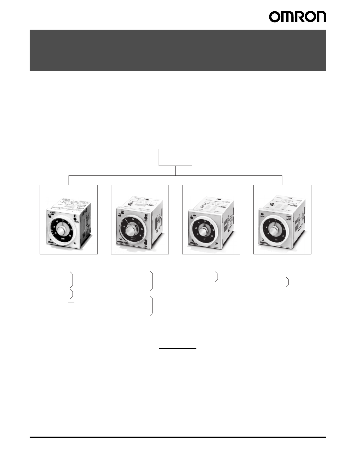
■ Broad Line-up of H3CR Series
H3CR
H3CR-A
Multifunctional Timer Twin Timer Star-delta Timer Power OFF-delay Timer
H3CR-A
H3CR-AS
H3CR-AP
H3CR-A8
H3CR-A8S
H3CR-A8E
11-pin model
8-pin model
8-pin with
instantaneous
contact output
model
H3CR-F
H3CR-FN
H3CR-F-300
H3CR-FN-300
H3CR-F8
H3CR-F8N
H3CR-F8-300
H3CR-F8N-300
11-pin model
8-pin model
H3CR-GH3CR-F
H3CR-G8L
H3CR-G8EL
8-pin model
H3CR-H
H3CR-HRL
H3CR-H8L
H3CR-H8RL
11-pin model
8-pin model
Note: H3CR-AS, H3CR-A8S: Transistor output models
Solid-state Timer
H3CR-A........................................................................................................................................... 2
H3CR-F........................................................................................................................................... 24
H3CR-G .......................................................................................................................................... 30
H3CR-H .......................................................................................................................................... 37
Common to ALL Timers
Operation ........................................................................................................................................ 45
Accessories..................................................................................................................................... 47
Safety Precautions.......................................................................................................................... 51
Contents
Solid-state Timer H3CR 1
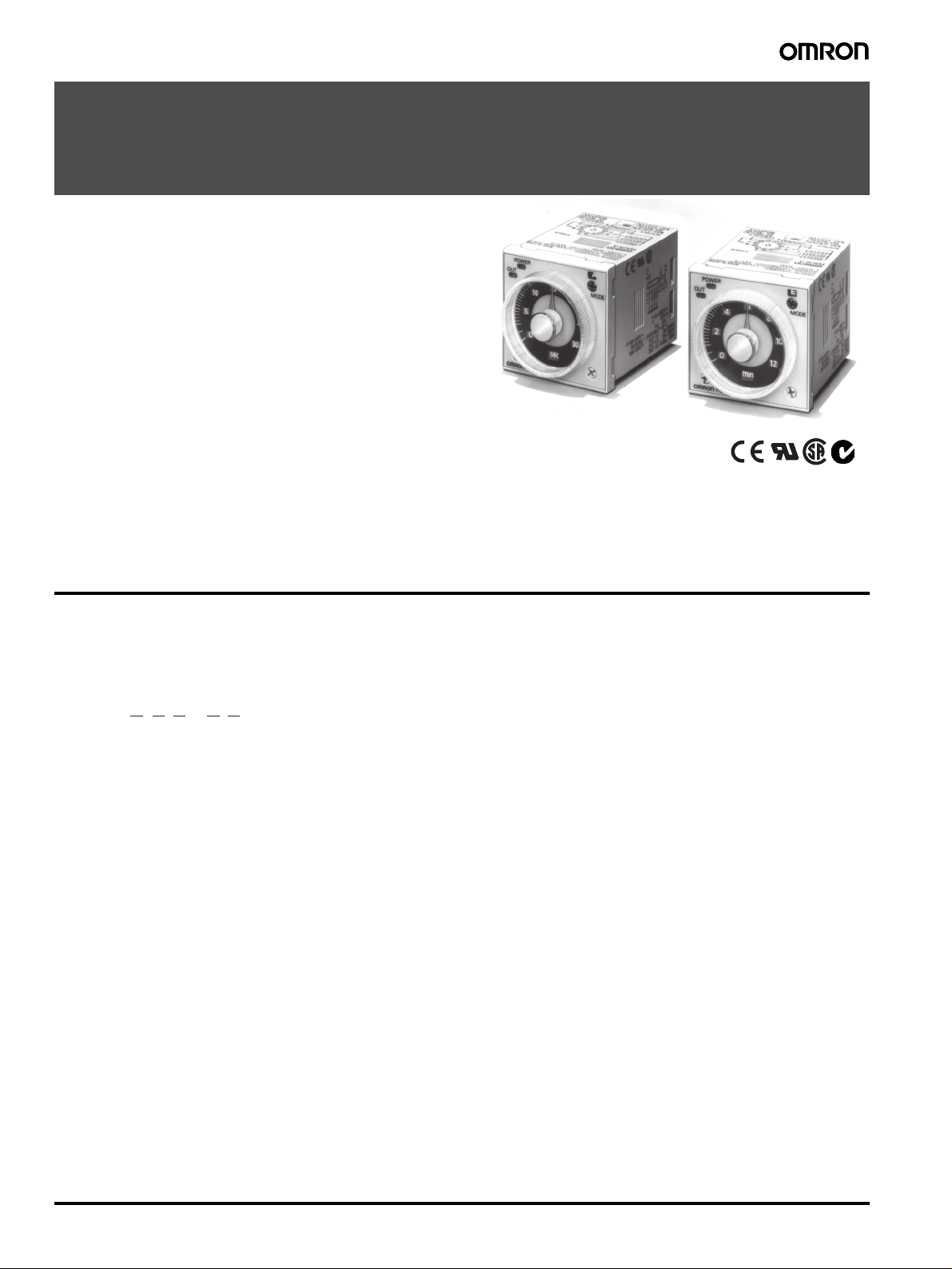
Solid-state Multi-functional Timer
H3CR-A
DIN 48 × 48-mm State-of-the-art
Multifunctional Timer
• A wider power supply range reduces the number of timer models kept in stock.
• A wide range of applications through six or four operating
modes.
• Reduced power consumption.
(Except for H3CR-A8E)
• Enables easy sequence checks through instantaneous outputs
for a zero set value at any time range.
• Length, when panel-mounted with a Socket, of 80 mm or less.
• Time Setting Rings enable consistent settings and limit the setting range.
• Panel Covers enable various panel designs.
• PNP input models available.
• Rich variety of inputs: Start, reset, and gate functions (11-pin
models and -AP models)
Model Number Structure
■ Model Number Legend
Note: This model number legend includes combinations that are not available. Before ordering, please check the List of Models on page 3 for avail-
ability.
H3CR-A@ @ @ - @ @
1. Number of Pins
None: 11-pin models
8: 8-pin models
2. Input Type for 11-pin Models
None: No-voltage input (NPN type)
P: Voltage input (PNP type)
3. Output
None: Relay output (DPDT)
S: Transistor output (NPN/PNP universal use)
E: Relay output (SPDT) with instantaneous relay output (SPDT)
4. Suffix
300: Dual mode models (signal ON/OFF-delay and one-shot)
301: Double time scale (range) models (0.1 s to 600 h)
5. Supply Voltage
100-240AC/100-125DC: 100 to 240 VAC/100 to 125 VDC
24-48AC/12-48DC: 24 to 48 VAC/12 to 48 VDC
24-48AC/DC: 24 to 48 VAC/VDC (Only for H3CR-A8E)
123 45
2 Solid-state Multi-functional Timer H3CR-A
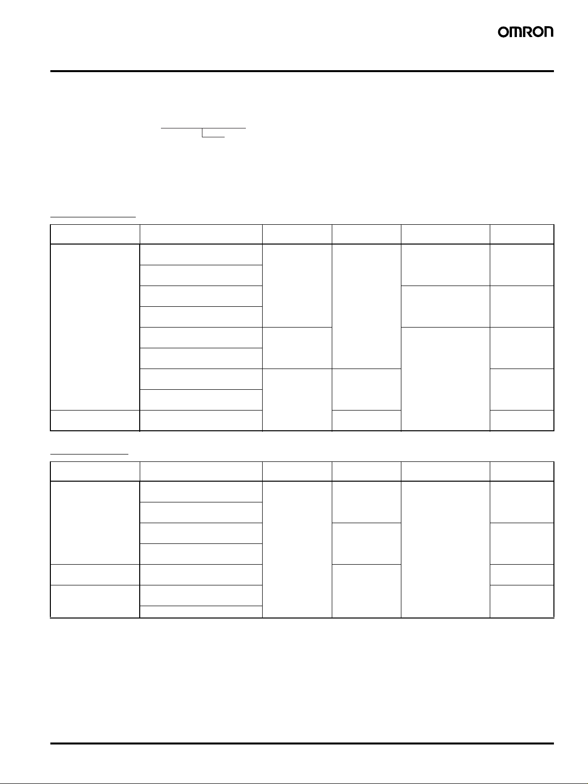
Ordering Information
■ List of Models
Note: 1. Specify both the model number and supply voltage when ordering.
Example: H3CR-A 100-240AC/100-125DC
Supply voltage
2. The operating modes are as follows
A: ON-delay D: Signal OFF-delay
B: Flicker OFF start E: Interval
B2: Flicker ON start G: Signal ON/OFF-delay
C: Signal ON/OFF-delay J: One-shot
11-pin Models
Output Supply voltage Input type Time range Operating mode
Contact 100 to 240 VAC (50/60 Hz)/
Transistor
(Photocoupler)
100 to 125 VDC
24 to 48 VAC (50/60 Hz)/
12 to 48 VDC
100 to 240 VAC (50/60 Hz)/
100 to 125 VDC
24 to 48 VAC (50/60 Hz)/
12 to 48 VDC
100 to 240 VAC (50/60 Hz)/
100 to 125 VDC
24 to 48 VAC (50/60 Hz)/
12 to 48 VDC
100 to 240 VAC (50/60 Hz)/
100 to 125 VDC
24 to 48 VAC (50/60 Hz)/
12 to 48 VDC
24 to 48 VAC (50/60 Hz)/
12 to 48 VDC
No-voltage input 0.05 s to 300 h Six multi-modes: A, B,
Voltage input Six multi-modes: A, B,
No-voltage input 0.1 s to 600 h H3CR-A-301
(See note 2)
B2, C, D, E
Dual-modes: G, J H3CR-A-300
B2, C, D, E
0.05 s to 300 h H3CR-AS
Model
(See note 1.)
H3CR-A
H3CR-AP
8-pin Models
Output Supply voltage Input type Time range Operating mode
Contact 100 to 240 VAC (50/60 Hz)/
Transistor
(Photocoupler)
Time-limit contact and
instantaneous contact
100 to 125 VDC
24 to 48 VAC (50/60 Hz)/
12 to 48 VDC
100 to 240 VAC (50/60 Hz)/
100 to 125 VDC
24 to 48 VAC (50/60 Hz)/
12 to 48 VDC
24 to 48 VAC (50/60 Hz)/
12 to 48 VDC
100 to 240 VAC (50/60 Hz)/
100 to 125 VDC
24 to 48 VAC/VDC (50/60 Hz)
(See note 2)
No-input available 0.05 s to 300 h Four multi-modes: A,
B2, E, J
(Power supply start)
0.1 s to 600 h H3CR-A8-301
0.05 s to 300 h H3CR-A8S
Model
(See note 1.)
H3CR-A8
H3CR-A8E
Solid-state Multi-functional Timer H3CR-A 3
■ Accessories (Order Separately)
Name/specifications Models
Flush Mounting Adapter Y92F-30
Y92F-73
Y92F-74
Mounting Track 50 cm (l)
1 m (l)
1 m (l)
End Plate PFP-M
Spacer PFP-S
Protective Cover Y92A-48B
Track Mounting/
Front Connecting Socket
Back Connecting Socket 8-pin P3G-08
Time Setting Ring Setting a specific time Y92S-27
Panel Cover (See note 2) Light gray (5Y7/1) Y92P-48GL
Hold-down Clip (See note 3) For PL08 and PL11 Sockets Y92H-7
Note: 1. Y92A-48G is a finger safe terminal cover which is attached to the P3G-08 or P3GA-11 Socket.
2. The Time Setting Ring and Panel Cover are sold together.
3. Hold-down Clips are sold in sets of two.
8-pin P2CF-08
8-pin, finger safe type P2CF-08-E
11-pin P2CF-11
11-pin, finger safe type P2CF-11-E
8-pin, finger safe type P3G-08 with Y92A-48G (See note 1)
11-pin P3GA-11
11-pin, finger safe type P3GA-11 with Y92A-48G (See note 1)
Limiting the setting range Y92S-28
Black (N1.5) Y92P-48GB
Medium gray (5Y5/1) Y92P-48GM
For PF085A Socket Y92H-8
× 7.3 mm (t) PFP-50N
× 7.3 mm (t) PFP-100N
× 16 mm (t) PFP-100N2
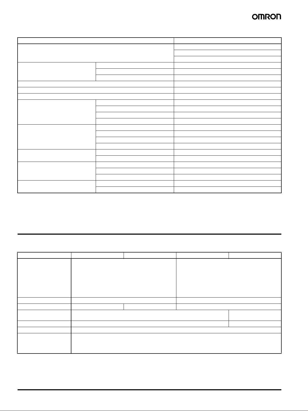
Specifications
■ General
Item H3CR-A/-AS H3CR-AP H3CR-A8/-A8S H3CR-A8E
Operating mode A: ON-delay
B: Flicker OFF start
B2: Flicker ON start
C: Signal ON/OFF-delay
D: Signal OFF-delay
E: Interval
G: Signal ON/OFF-delay (Only for H3CR-A-300)
J: One-shot (Only for H3CR-A-300)
Pin type 11-pin 8-pin
Input type No-voltage input Voltage input ---
Time-limit output type H3CR-A/-A8/-AP: Relay output (DPDT)
H3CR-AS/-A8S: Transistor output (NPN/PNP universal)*
Instantaneous output type --- Relay output (SPDT)
Mounting method DIN track mounting, surface mounting, and flush mounting
Approved standards UL508, CSA C22.2 No.14, NK, Lloyds
Conforms to EN61812-1 and IEC60664-1 (VDE0110) 4kV/2.
Output category according to EN60947-5-1 for Timers with Contact Outputs.
Output category according to EN60947-5-2 for Timers with Transistor Outputs.
*The internal circuits are optically isolated from the output. This enables universal application as NPN or PNP transistor.
A: ON-delay (power supply start)
B2: Flicker ON start (power supply start)
E: Interval (power supply start)
J: One-shot (power supply start)
Relay output (SPDT)
4 Solid-state Multi-functional Timer H3CR-A
■ Time Ranges
Note: When the time setting knob is turned below “0” until the point where the time setting knob stops, the output will operate instantaneously at
all time range settings.
Standard (0.05-s to 300-h) Models
Time unit s (sec) min (min) h (hrs)
Full scale
setting
1.2 0.05 to 1.2 0.12 to 1.2 1.2 to 12
3 0.3 to 3 3 to 30
×10 h (10 h)
12 1.2 to 12 12 to 120
30 3 to 30 30 to 300
Double (0.1-s to 600-h) Models
Time unit s (sec) min (min) h (hrs) ×10 h (10 h)
Full scale
setting
2.4 0.1 to 2.4 0.24 to 2.4 2.4 to 24
6 0.6 to 6 6 to 60
24 2.4 to 24 24 to 240
60 6 to 60 60 to 600
■ Ratings
Rated supply voltage (See notes 1, 2, and 5.) 100 to 240 VAC (50/60 Hz)/100 to 125 VDC, 24 to 48 VAC (50/60 Hz)/12 to 48 VDC (24 to 48 VAC/VDC for H3CR-
Operating voltage range 85% to 110% of rated supply voltage (90% to 110% at 12 VDC)
Powe r r es et Minimum power-opening time: 0.1 s
Input No-voltage Input
Power consumption H3CR-A/-A8
Control outputs Time limit contacts: 5 A at 250 VAC/30 VDC, 0.15 A at 125 VDC, resistive load (cos
Note: 1. DC ripple rate: 20% max. if the power supply incorporates a single-phase, full-wave rectifier.
2. Do not use an inverter output as the power supply. Refer to Power Supplies in Safety Precautions for All Timers on page 51 for details.
3. Models with 24-to-48-VAC or 12-to-48-VDC power supply have inrush current. Caution is thus required when turning ON and OFF power
to the Timer with a non-contact output from a device such as a sensor. (Models with an inrush current of approximately 50 mA and a 24VDC power supply are available (the H3CR-A-302 and H3CR-A8-302).)
4. The values are for when the terminals 2 and 7 and terminals 10 and 6 are short-circuited, and include the consumption current of the
input circuit.
5. Refer to Power Supplies in Safety Precautions for All Timers on page 51 when using the Timer together with a 2-wire AC proximity sensor.
A8E) (See note3.)
ON impedance: 1 kΩ max.
ON residual voltage: 1 V max.
OFF impedance: 100 k
Voltage Input
Max. permissible capacitance between inputs lines (terminals 6 and 7): 1,200 pF
Load connectable in parallel with inputs (terminals 6 and 7).
• 100 to 240 VAC/100 to 125 VDC
High (logic) level: 85 to 264 VAC/85 to 137.5 VDC
Low (logic) level: 0 to 10 VAC/0 to 10 VDC
• 24 to 48 VAC/12 to 48 VDC
High (logic) level: 20.4 to 52.8 VAC/10.8 to 52.8 VDC
Low (logic) level: 0 to 2.4 VAC/0 to 1.2 VDC
• 100 to 240 VAC/100 to 125 VDC
(When at 240 VAC, 60 Hz)
• 24 to 48 VAC/12 to 48 VDC
(When at 24 VDC)
H3CR-AP (See note 3)
• 100 to 240 VAC/100 to 125 VDC
(When at 240 VAC, 60 Hz)
• 24 to 48 VAC/12 to 48 VDC
(When at 24 VDC)
H3CR-A8E
• 100 to 240 VAC/100 to 125 VDC
(When at 240 VAC, 60 Hz)
• 24 to 48 VAC/VDC
(When at 24 VDC)
H3CR-AS/-A8S
• 24 to 48 VAC/12 to 48 VDC
(When at 24 VDC)
Transistor output: Open collector (NPN/PNP), 100 mA max. at 30 VDC max.,
Instantaneous contact: 5 A at 250 VAC/30 VDC, 0.15 A at 125 VDC, resistive load (cos
Relay ON: approx. 2.0 VA (1.6 W) Relay OFF: approx. 1.3 VA (1.1 W)
Relay ON: approx. 0.8 W Relay OFF: approx. 0.2 W
Relay ON: approx. 2.5 VA (2.2 W) (See note 4.) Relay OFF: approx. 1.8 VA (1.7 W) (See note 4.)
Relay ON: approx. 0.9 W (See note 4.) Relay OFF: approx. 0.3 W (See note 4.)
Relay ON/OFF: approx. 2 VA (0.9 W)
Relay ON/OFF: approx. 0.9 W
Output ON: 0.3 W Output OFF: 0.2 W
Ω min.
residual voltage: 2 V max.
φ = 1)
φ = 1)
Solid-state Multi-functional Timer H3CR-A 5
■ Characteristics
Accuracy of operating
time
Setting error
Reset time Min. power-opening time: 0.1 s max.
Reset voltage 10% max. of rated supply voltage
Influence of voltage
Influence of temperature
Insulation resistance 100 M
Dielectric strength 2,000 VAC (1,000 VAC for H3CR-A@S), 50/60 Hz for 1 min (between current-carrying metal parts and exposed non-
Impulse withstand
voltage
Noise immunity
Static immunity Malfunction: 8 kV
Vibration resistance Destruction: 10 to 55 Hz with 0.75-mm single amplitude each in 3 directions for 2 hours each
Shock resistance
Ambient temperature Operating:
Ambient humidity Operating: 35% to 85%
Life expectancy Mechanical: 20,000,000 operations min. (under no load at 1,800 operations/h)
EMC (EMI) EN61812-1
Case color Light gray (Munsell 5Y7/1)
Degree of protection IP40 (panel surface)
Weight Approx. 90 g
Note: 1. The value is ±5% FS +100 ms to −0 ms max. when the C, D, or G mode signal of the H3CR-AP is OFF.
2. Refer to the Life-test Curve.
±0.2% FS max. (±0.2%±10 ms max. in a range of 1.2 s)
±5% FS ±50 ms (See note 1)
Min. pulse width: 0.05 s (H3CR-A/-AS)
±0.2% FS max. (±0.2%±10 ms max. in a range of 1.2 s)
±1% FS max. (±1%±10 ms max. in a range of 1.2 s)
Ω min. (at 500 VDC)
current-carrying metal parts)
2,000 VAC (1,000 VAC for H3CR-A@S), 50/60 Hz for 1 min (between control output terminals and operating circuit)
2,000 VAC, 50/60 Hz for 1 min (between contacts of different polarities)
1,000 VAC, 50/60 Hz for 1 min (between contacts not located next to each other)
2,000 VAC, 50/60 Hz for 1 min (between input and control output terminals and operation circuit) for H3CR-AP
3 kV (between power terminals) for 100 to 240 VAC/100 to 125 VDC, 1 kV for 24 to 48 VAC/12 to 48 VDC
4.5 kV (between current-carrying terminal and exposed non-current-carrying metal parts) for 100 to 240 VAC/100 to
125 VDC, 1.5 kV for 24 to 48 VAC/12 to 48 VDC and 24 to 48 VAC/VDC
±1.5 kV (between power terminals) and ±600 V (between no-voltage input terminals), square-wave noise by noise
simulator (pulse width: 100 ns/1
Destruction: 15 kV
Malfunction: 10 to 55 Hz with 0.5-mm single amplitude each in 3 directions for 10 minutes each
Destruction: 1,000 m/s
Malfunction: 100 m/s
Storage:
Electrical: 100,000 operations min. (5 A at 250 VAC, resistive load at 1,800 operations/h) (See note 2)
Emission Enclosure: EN55011 Group 1 class A
Emission AC Mains: EN55011 Group 1 class A
(EMS) EN61812-1
Immunity ESD: IEC61000-4-2: 6 kV contact discharge (level 3)
Immunity RF-interference from AM Radio Waves: IEC61000-4-3: 10 V/m (80 MHz to 1 GHz) (level 3)
Immunity RF-interference from Pulse-modulated Radio Waves:IEC61000-4-3: 10 V/m (900
Immunity Conducted Disturbance: IEC61000-4-6: 10 V (0.15 to 80 MHz) (level 3)
Immunity Burst: IEC61000-4-4: 2 kV power-line (level 3)
Immunity Surge: IEC61000-4-5: 1 kV line to line (level 3)
−10°C to 55°C (with no icing)
−25°C to 65°C (with no icing)
2
2
3 times each in 6 directions
µs, 1-ns rise)
3 times each in 6 directions
8 kV air discharge (level 3)
±5 MHz) (level 3)
2 kV I/O signal-line (level 4)
2 kV line to ground (level 3)
6 Solid-state Multi-functional Timer H3CR-A
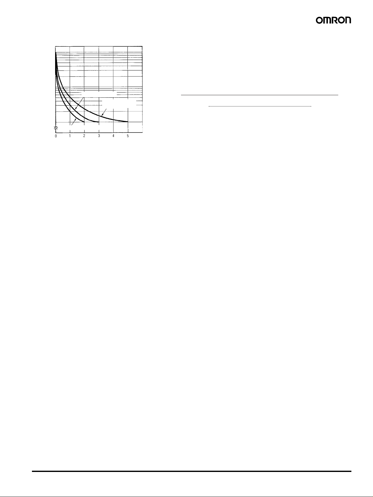
■ Life-test Curve
10,000
)
3
5,000
1,000
500
Switching operations (x 10
100
30 VDC L/R = 7 ms
250 VAC (cosφ = 0.4)
Load current (A)
250 VAC/30 VDC
(cosφ = 1)
Reference: A maximum current of 0.15 A can be switched at 125 VDC (cosφ = 1)
and a maximum current of 0.1 A can be switched if L/R is 7 ms. In
both cases, a life of 100,000 operations can be expected.
The minimum applicable load is 10 mA (100 mA for H3CR-A8E) at
5 VDC (failure level: P).
Solid-state Multi-functional Timer H3CR-A 7
Connections
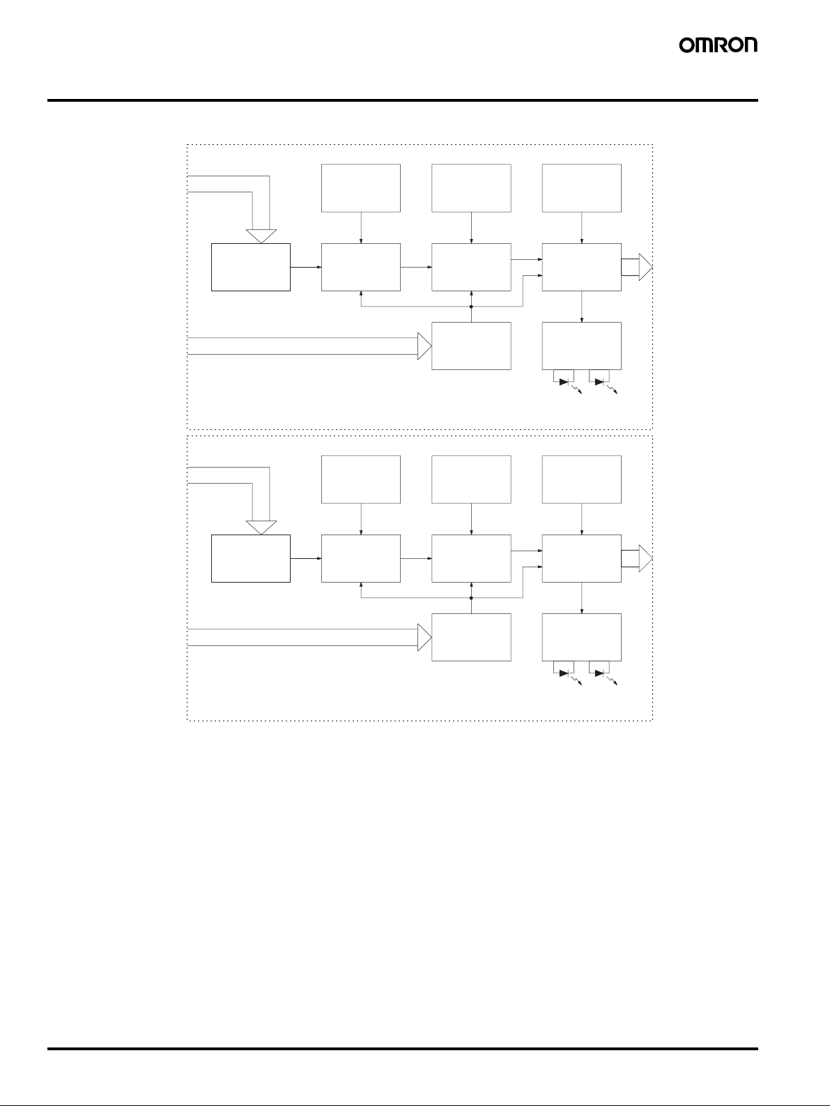
■ Block Diagrams
H3CR-A/AS
AC (DC) input
Zero setting
detection
circuit
Time range/
unit selectors
Operating
mode selector
H3CR-AP
Power supply
circuit
Reset input, start input, and gate input
AC (DC) input
Power supply
circuit
Start
Oscillation
circuit
Zero setting
detection
circuit
Oscillation
circuit
Counting
circuit
Input circuit
Time range/
unit selectors
Counting
circuit
Input circuit
Output circuit
Indicator
circuit
Power-ON
indicator
Operating
mode selector
Output circuit
Indicator
circuit
Output-ON
indicator
8 Solid-state Multi-functional Timer H3CR-A
Power-ON
indicator
Output-ON
indicator
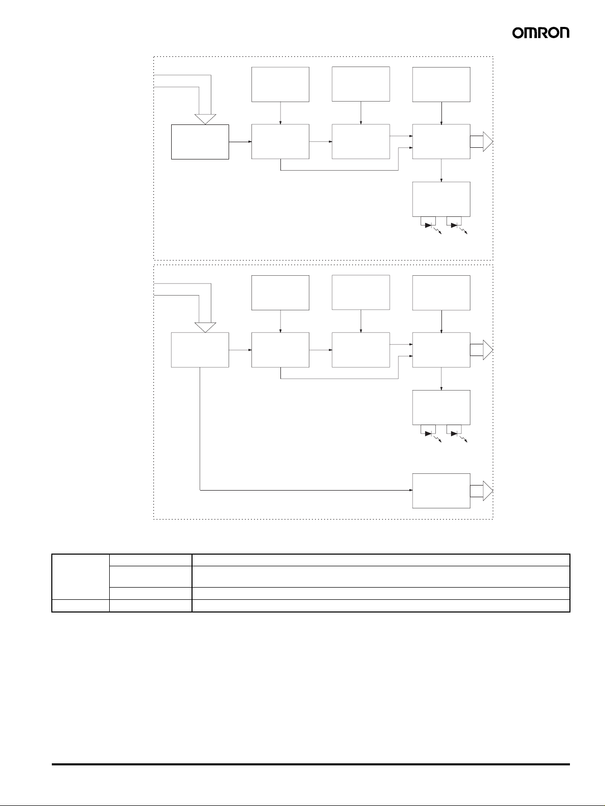
H3CR-A8/A8S
AC (DC) input
Zero setting
detection
circuit
Time range/
unit selectors
Operating
mode selector
H3CR-A8E
Power supply
circuit
AC (DC) input
Power supply
circuit
Oscillation
circuit
Zero setting
detection
circuit
Oscillation
circuit
Counting
circuit
Time range/
unit selectors
Counting
circuit
Output circuit
Indicator
circuit
Power-ON
indicator
Operating
mode selector
Output circuit
Indicator
circuit
Output-ON
indicator
Power-ON
indicator
Instantaneous
output circuit
Output-ON
indicator
■ I/O Functions
Inputs (for -A/
-AS models)
Outputs Control output Outputs are turned ON according to designated output mode when preset value is reached.
Note: H3CR-AP incorporates start input only.
Start Starts time-measurement.
Reset Interrupts time-measurement and resets time-measurement value. No time-measurement is made and
control output is OFF while the reset input is ON.
Gate Prohibits time-measurement.
Solid-state Multi-functional Timer H3CR-A 9
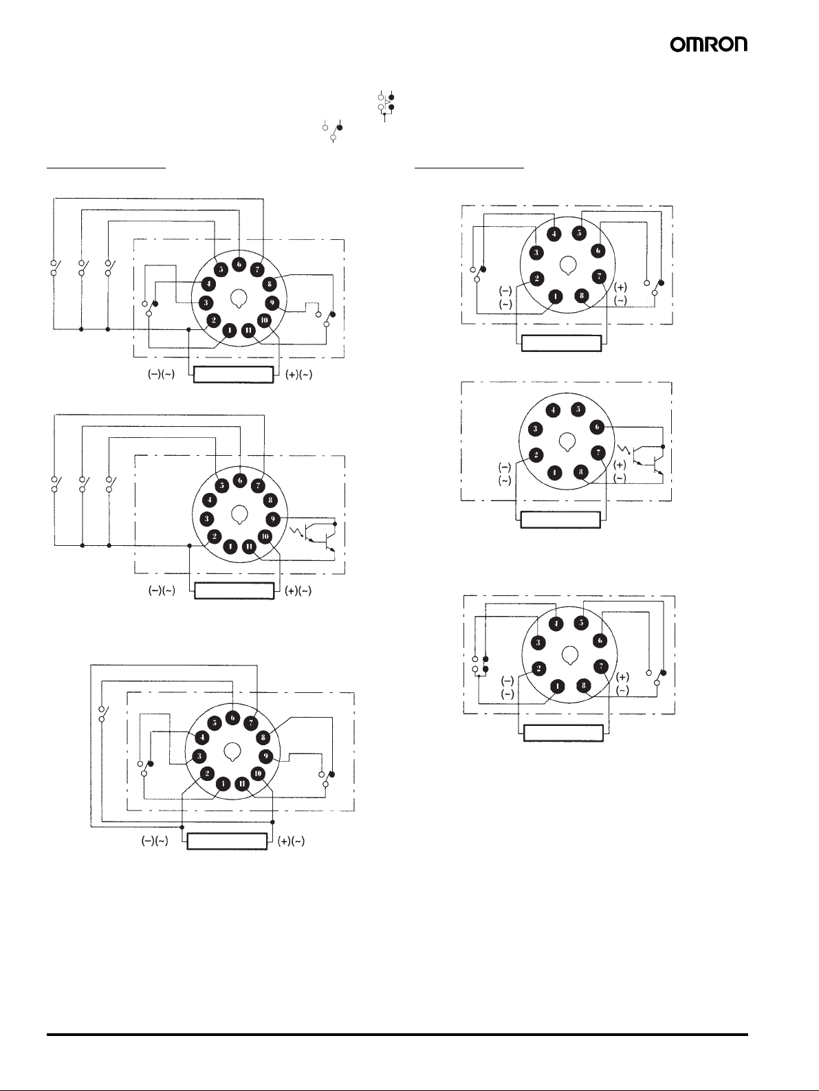
■ Terminal Arrangement
Note: The delayed contact of conventional Timers was indicated as
The contact symbol of the H3CR-A is indicated as because its operating mode is six multi-modes (four multi-modes for the H3CR-A8).
11-pin Models
H3CR-A/-A-300/-A-301 (Contact Output)
Reset input
Start input
Gate input
Power supply
H3CR-AS (Transistor Output)
Reset input
Start input
Gate input
8-pin Models
H3CR-A8/-A8-301 (Contact Output)
Power supply
H3CR-A8S (Transistor Output)
Power supply
Note: Terminals 1, 3, 4, and 5 are empty. Terminals 2 and 7 are the
same as for the H3CR-A8.
Power supply
Note: Terminals 1, 3, 4, and 8 are empty. Terminals 2, 5, 6, 7, and 10
are the same as for the H3CR-A.
H3CR-AP (Contact Output)
Start input
Power supply
Note: 1. Terminal 5 is empty.
2. Separate power supplies can be used for the Timer and in-
puts.
H3CR-A8E (Contact Output)
Power supply
10 Solid-state Multi-functional Timer H3CR-A
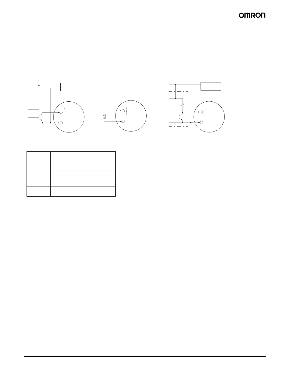
■ Input Connections
H3CR-A/-AS
The inputs of the H3CR-A/-AS are no-voltage (short-circuit or open) inputs.
No-voltage Inputs
No-contact Input Contact Input No-contact Input
(Connection to NPN open
collector output sensor.)
12 to 24 VDC
(sensor power supply)
Sensor
+
DC power
−
supply
Timer
5
6
7
2
Input (0 V)
Gate
Start
Reset
Timer
5
Gate
6
Start
7
Reset
2
Input (0 V)
(Connection to a voltage
output sensor.)
12 to 24 VDC
(sensor power supply)
Sensor
DC power
+
−
supply
Timer
5
6
7
2
Gate
Start
Reset
Input (0 V)
Operates with transistor ON
No-voltage Input Signal Levels
No-contact
input
1. Short-circuit level
Transistor ON
Residual voltage: 1 V max.
Impedance when ON: 1 kΩ max.
2. Open level
Transistor OFF
Impedance when OFF: 100 kΩ min.
Contact
input
Use contacts which can adequately switch 0.1 mA at 5 V
Operates with relay ON
Operates with transistor ON
Solid-state Multi-functional Timer H3CR-A 11
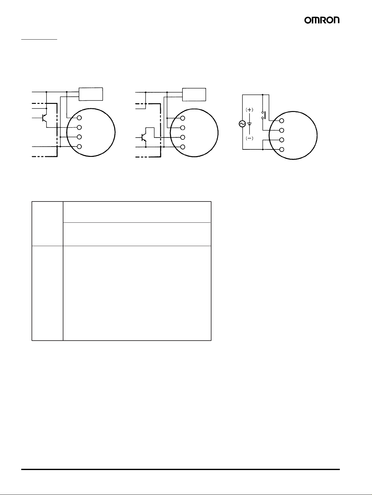
H3CR-AP
The start input of the H3CR-AP is voltage input. (Voltage imposition or open)
Voltage Inputs
No-contact Input No-contact Input Contact Input
(Connection to PNP open
collector output sensor)
12 to 24 VDC
(sensor power supply)
Sensor
Operates with PNP transistor ON
DC power
+
supply
−
Timer
10
6
7
Powe r
supply (+)
Start
Input 0V
Powe r
supply
(−)
(Connection to NPN open
collector output sensor)
12 to 24 VDC
(sensor power supply)
Sensor
Operates with NPN transistor ON
DC power
+
supply
−
Timer
10
6
7
22
Powe r
supply (+)
Start
Input 0V
Powe r
supply
(−)
AC power supply
Operates with relay ON
DC power supply
Timer
10
6
7
2
Powe r
supply (+)
Start
Input 0V
Powe r
supply
(−)
Voltage Input Signal Levels
No-contact
input
1. Transistor ON
Residual voltage: 1 V max.
The voltage between terminals 6 and 7 must be 10.8 VDC min.
2. Transistor OFF
Leakage current: 0.01 mA max.
The voltage between terminals 6 and 7 must be 1.2 VDC max.
Contact
input
Use contacts that can adequately switch 0.1 mA at each operating voltage.
The voltage between terminals 6 and 7 with contacts ON or
OFF must satisfy the specified value.
Contacts ON
100-to-240-VAC and 100-to-125-VDC models: 85 to 264 VAC
or 85 to 137.5 VDC
24-to-48-VAC and 12-to-48-VDC models: 20.4 to 52.8 VAC or
10.8 to 52.8 VDC
Contacts OFF
100-to-240-VAC and 100-to-125-VDC models: 0 to 10 VAC or
0 to 10 VDC
24-to-48-VAC and 12-to-48-VDC models: 0 to 2.4 VAC or 0 to
1.2 VDC
Note: The input circuit is isolated from the
power supply circuit. Thus, an NPN
transistor can be connected.
Note: Refer to the signal levels in the fol-
lowing table and be aware of the
minimum applicable load of the relay.
12 Solid-state Multi-functional Timer H3CR-A
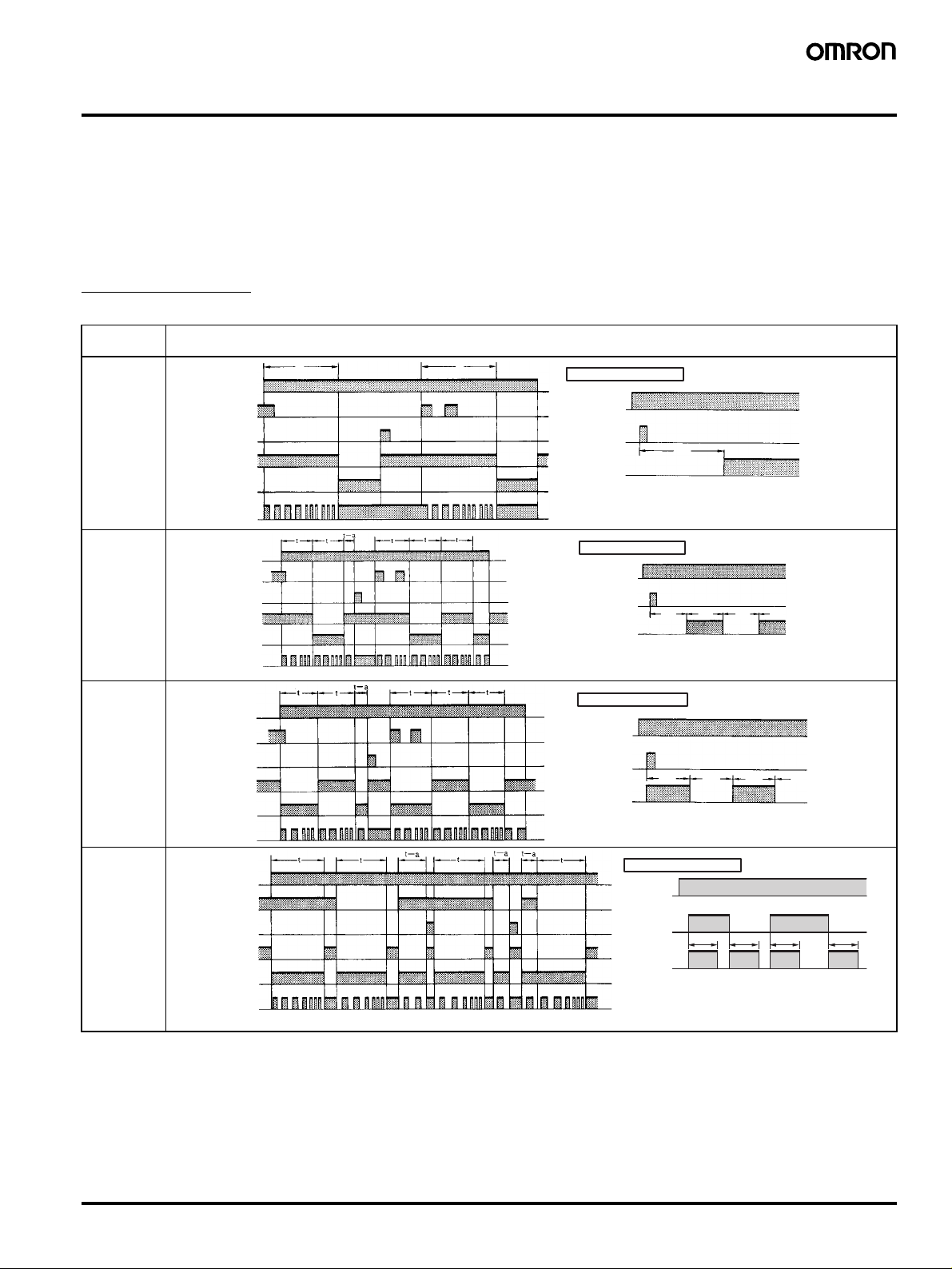
Operation
■ Timing Chart
Note: 1. The minimum power-opening time (“Rt”) is 0.1 s.
2. The minimum input pulse width (for start, reset) is 0.05 s.
3. The letter “t” in the timing charts stands for the set time and “t–a” means that the period is less than the time set.
4. Power supply start in mode J is also possible for H3CR-A8/-A8E/-A8S/-A8-301 models.
5. Refer to page 19 for application examples.
H3CR-A/-AS/-AP*
*H3CR-AP model incorporates start input only.
Operating
mode
A: ON-delay
B:
Flicker OFF
start
B2:
Flicker ON
start
C:
Signal ON/
OFFdelay
Powe r
Start
Reset
Output relay (NC)
Output relay (NO)
(Output indicator)
Power indicator
Powe r
Start
Reset
Output relay (NC)
Output relay (NO)
(Output indicator)
Power indicator
Powe r
Start
Reset
Output relay (NC)
Output relay (NO)
(Output indicator)
Power indicator
Powe r
Start
Reset
Output relay (NC)
Output relay (NO)
(Output indicator)
Power indicator
t t
Timing chart
Basic operation
Powe r
Start
(See note)
Output
t
Note: Start input is invalid while the
Timer is in operation.
Basic operation
Powe r
Start
(See note)
Output
t t t t
Note: Start input is invalid while
the Timer is in operation.
Basic operation
Powe r
Start
(See note)
Output
t
Note: Start input is invalid while the
Timer is in operation.
Basic operation
Powe r
Start
(See note)
Output
Note: Start input is valid and re-
t t
t
tttt
triggerable while the Timer is
in operation.
Solid-state Multi-functional Timer H3CR-A 13
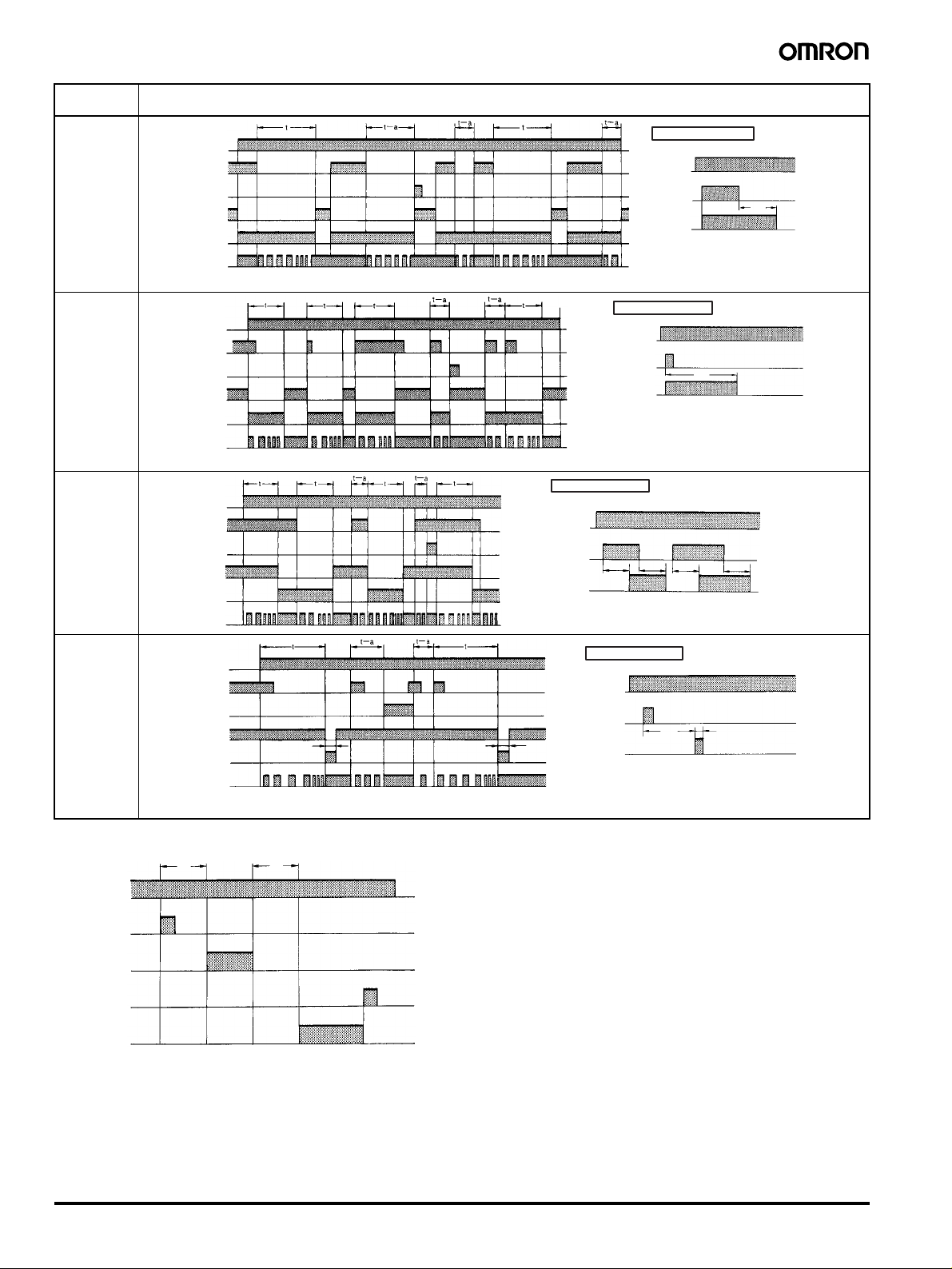
Operating
mode
D:
Signal OFFdelay
E:
Interval
G:
Signal ON/
OFFdelay
J:
One-shot output
Powe r
Start
Reset
Output relay (NC)
Output relay (NO)
(Output indicator)
Power indicator
Powe r
Start
Reset
Output relay (NC)
Output relay (NO)
(Output indicator)
Power indicator
Powe r
Start
Reset
Output relay (NC)
Output relay (NO)
(Output indicator)
Power indicator
Powe r
Start
Reset
Output relay (NC)
Output relay (NO)
(Output indicator)
Power indicator
1±0.6 s
(Fixed)
Timing chart
1±0.6 s
(Fixed)
Basic operation
Powe r
Start
(See note)
Output
Note: Start input is valid and
re-triggerable while the
Timer is in operation.
Basic operation
Powe r
Start
(See note)
Output
t
Note: Start input is valid and
re-triggerable while
the Timer is in operation.
Basic operation
Powe r
Start
(See note)
Output
tttt
Note: Start input is valid and re-triggera-
ble while the Timer is in operation.
Basic operation
Powe r
Start
(See note)
Output
t
1±0.6 s
(Fixed)
Note: Start input is valid and re-
triggerable while the Timer
is in operation.
t
Gate Signal Input
t1 t2
ON
Powe r
OFF
ON
Start
OFF
ON
Gate
OFF
ON
Reset
OFF
Output
ON
relay
OFF
Note: 1. This timing chart indicates the gate input in op-
erating mode A (ON-delay operation).
2. The set time is the sum of t
1 and t2.
3. H3CR-AP model incorporates start input only.
14 Solid-state Multi-functional Timer H3CR-A
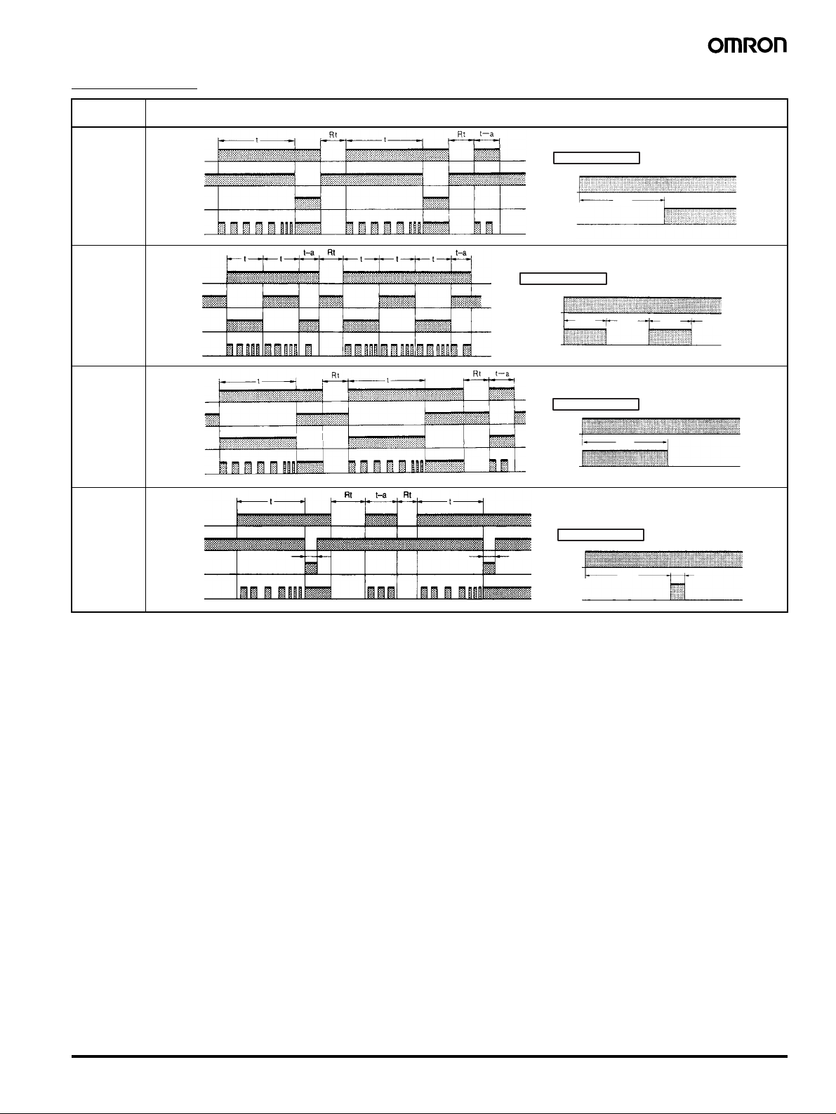
H3CR-A8/-A8S
Operating
mode
A:
ON-delay
:
B
2
Flicker ON
start
E:
Interval
J:
One-shot output
Powe r
Output relay
(NC)
Output relay
(NO) (output
indicator)
Powe r
indicator
Powe r
Output relay
(NC)
Output relay
(NO) (output
indicator)
Powe r
indicator
Powe r
Output relay
(NC)
Output relay
(NO) (output
indicator)
Powe r
indicator
Powe r
Output relay
(NC)
Output relay
(NO) (output
indicator)
Powe r
indicator
1±0.6 s
(Fixed)
Timing chart
1±0.6 s
(Fixed)
Basic operation
Powe r
Output
Basic operation
Powe r
t t t t
Output
Basic operation
Powe r
Output
Basic operation
Powe r
Output
t
t
t
1±0.6 s
(Fixed)
Note: 1. The minimum power-opening time (“Rt”) is 0.1 s.
2. The letter “t” in the timing charts stands for the set time and “t–a” means that the period is less than the time set.
Solid-state Multi-functional Timer H3CR-A 15
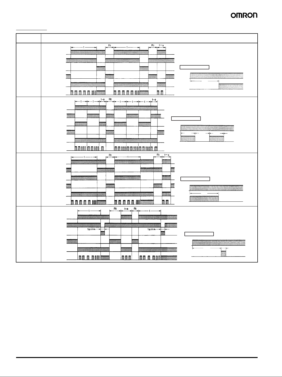
H3CR-A8E
Operating
Timing chart
mode
A:
ON-delay
:
B
2
Flicker ON
start
Instantaneous
output relay (NC)
Instantaneous
output relay (NO)
Instantaneous
output relay (NC)
Instantaneous
output relay (NO)
Powe r
Output relay
(NC)
Output relay
(NO) (output
indicator)
Power indicator
Powe r
Output relay
(NC)
Output relay
(NO) (output
indicator)
Power indicator
Basic operation
Powe r
Output
Basic operation
Powe r
t ttt
Output
E:
Interval
Powe r
Output relay
(NC)
Output relay
(NO) (output
indicator)
Instantaneous
output relay (NC)
Instantaneous
output relay (NO)
Power indicator
Basic operation
Powe r
Output
J:
One-shot output
Instantaneous
output relay (NC)
Instantaneous
output relay (NO)
Powe r
Output relay
(NC)
Output relay
(NO) (output
indicator)
Power indicator
(Fixed) (Fixed)
Basic operation
Powe r
Output
Note: 1. The minimum power-opening time (“Rt”) is 0.1 s.
2. The letter “t” in the timing charts stands for the set time and “t–a” means that the period is less than the time set.
t
t
t
1±0.6 s
(Fixed)
16 Solid-state Multi-functional Timer H3CR-A
 Loading...