

Omron G9SP-N20S, G9SP-N10D, G9SP-N10S Operation Manuals

Cat. No. Z922-E1-07
G9SP Series
Safety Controller
OPERATION M ANUAL

NOTE
All rights reserved. No part of this publication may be reproduced, stored in a retrieval system, or transmitted, in
any form, or by any means, mechanical, electronic, photocopying, recording, or otherwise, without the prior
written permission of OMRON.
No patent liability is assumed with respect to the use of the information contained herein. Moreover, because
OMRON is constantly striving to improve its high-quality products, the information contained in this manual is
subject to change without notice. Every precaution has been taken in the preparation of this manual. Nevertheless, OMRON assumes no responsibility for errors or omissions. Neither is any liability assumed for damages
resulting from the use of the information contained in this publication.
Trademarks
• Microsoft, Windows, and Windows Vista are either registered trademarks or trademarks of Microsoft Corporation
in the United States and other countries.
Other company names and product names in this document are the trademarks or registered trademarks of their
respective companies.
Copyrights
Microsoft product screen shots reprinted with permission from Microsoft Corporation.

G9SP-series Safety Controller:
G9SP-N@@@
Operation Manual
Revised December 2016

iv

TABLE OF CONTENTS
Introduction . . . . . . . . . . . . . . . . . . . . . . . . . . . . . . . . . . . . . . . . . . . . . . . . . . . . . . . . . . . . . . . . . . . . . ix
Manual Configuration . . . . . . . . . . . . . . . . . . . . . . . . . . . . . . . . . . . . . . . . . . . . . . . . . . . . . . . . . . . . . x
Sections in this Manual . . . . . . . . . . . . . . . . . . . . . . . . . . . . . . . . . . . . . . . . . . . . . . . . . . . . . . . . . . . . xi
Safety Precautions . . . . . . . . . . . . . . . . . . . . . . . . . . . . . . . . . . . . . . . . . . . . . . . . . . . . . . . . . . . . . . . . xv
Precautions for Safe Use . . . . . . . . . . . . . . . . . . . . . . . . . . . . . . . . . . . . . . . . . . . . . . . . . . . . . . . . . . . xviii
Precautions for Compliance with UL Standards and CSA Standards . . . . . . . . . . . . . . . . . . . . . . . . xxi
Regulations and Standards . . . . . . . . . . . . . . . . . . . . . . . . . . . . . . . . . . . . . . . . . . . . . . . . . . . . . . . . . xxii
Glossary . . . . . . . . . . . . . . . . . . . . . . . . . . . . . . . . . . . . . . . . . . . . . . . . . . . . . . . . . . . . . . . . . . . . . . . xxiv
Overview
SECTION 1
Overview . . . . . . . . . . . . . . . . . . . . . . . . . . . . . . . . . . . . . . . . . 1
1-1 Overview and Features of the G9SP-series Controller . . . . . . . . . . . . . . . . . . . . . . . . . . . . . 2
1-2 Basic Operating Procedures. . . . . . . . . . . . . . . . . . . . . . . . . . . . . . . . . . . . . . . . . . . . . . . . . .9
Hardware Settings
SECTION 2
Part Names and Specifications . . . . . . . . . . . . . . . . . . . . . . . 11
2-1 G9SP-series Controllers. . . . . . . . . . . . . . . . . . . . . . . . . . . . . . . . . . . . . . . . . . . . . . . . . . . . . 12
2-2 Expansion I/O Units . . . . . . . . . . . . . . . . . . . . . . . . . . . . . . . . . . . . . . . . . . . . . . . . . . . . . . . 40
2-3 Option Units . . . . . . . . . . . . . . . . . . . . . . . . . . . . . . . . . . . . . . . . . . . . . . . . . . . . . . . . . . . . . 48
Hardware Settings
SECTION 3
Calculating Response Performance . . . . . . . . . . . . . . . . . . . 51
3-1 Startup Time . . . . . . . . . . . . . . . . . . . . . . . . . . . . . . . . . . . . . . . . . . . . . . . . . . . . . . . . . . . . . 52
3-2 Reaction Times . . . . . . . . . . . . . . . . . . . . . . . . . . . . . . . . . . . . . . . . . . . . . . . . . . . . . . . . . . . 53
v

TABLE OF CONTENTS
Hardware Settings
SECTION 4
Installation and Wiring . . . . . . . . . . . . . . . . . . . . . . . . . . . . . 55
4-1 Installation . . . . . . . . . . . . . . . . . . . . . . . . . . . . . . . . . . . . . . . . . . . . . . . . . . . . . . . . . . . . . . . 56
4-2 Wiring . . . . . . . . . . . . . . . . . . . . . . . . . . . . . . . . . . . . . . . . . . . . . . . . . . . . . . . . . . . . . . . . . . 63
Software Design
SECTION 5
Preparations for Using the G9SP Configurator. . . . . . . . . . 67
5-1 Overview . . . . . . . . . . . . . . . . . . . . . . . . . . . . . . . . . . . . . . . . . . . . . . . . . . . . . . . . . . . . . . . . 68
5-2 Installation . . . . . . . . . . . . . . . . . . . . . . . . . . . . . . . . . . . . . . . . . . . . . . . . . . . . . . . . . . . . . . . 70
Software Design
SECTION 6
Creating Configuration Data. . . . . . . . . . . . . . . . . . . . . . . . . 79
6-1 Overview . . . . . . . . . . . . . . . . . . . . . . . . . . . . . . . . . . . . . . . . . . . . . . . . . . . . . . . . . . . . . . . . 80
6-2 Creating Configuration Data . . . . . . . . . . . . . . . . . . . . . . . . . . . . . . . . . . . . . . . . . . . . . . . . .81
6-3 Designing Device Security . . . . . . . . . . . . . . . . . . . . . . . . . . . . . . . . . . . . . . . . . . . . . . . . . .88
6-4 Offline Simulation . . . . . . . . . . . . . . . . . . . . . . . . . . . . . . . . . . . . . . . . . . . . . . . . . . . . . . . . . 93
6-5 Creating and Using User-defined Function Blocks. . . . . . . . . . . . . . . . . . . . . . . . . . . . . . . . 97
Software Design
SECTION 7
Communications with a Standard PLC Using an Option Board103
7-1 Functionality for All Option Board's . . . . . . . . . . . . . . . . . . . . . . . . . . . . . . . . . . . . . . . . . . . 104
7-2 RS-232C Serial Communications . . . . . . . . . . . . . . . . . . . . . . . . . . . . . . . . . . . . . . . . . . . . . 115
7-3 Ethernet Communications . . . . . . . . . . . . . . . . . . . . . . . . . . . . . . . . . . . . . . . . . . . . . . . . . . . 123
vi

TABLE OF CONTENTS
Software Design
SECTION 8
Connecting Online and Downloading to the G9SP-series
Controller . . . . . . . . . . . . . . . . . . . . . . . . . . . . . . . . . . . . . . . . 131
8-1 Overview . . . . . . . . . . . . . . . . . . . . . . . . . . . . . . . . . . . . . . . . . . . . . . . . . . . . . . . . . . . . . . . . 132
8-2 Downloading Configuration Data to the G9SP-series Controller and Verification . . . . . . . . 133
8-3 Uploading Data from the G9SP-series Controller. . . . . . . . . . . . . . . . . . . . . . . . . . . . . . . . . 135
8-4 Resetting the G9SP-series Controller . . . . . . . . . . . . . . . . . . . . . . . . . . . . . . . . . . . . . . . . . . 136
8-5 Setting a Device Password. . . . . . . . . . . . . . . . . . . . . . . . . . . . . . . . . . . . . . . . . . . . . . . . . . .137
Software Design
SECTION 9
Operation and Operating Modes. . . . . . . . . . . . . . . . . . . . . . 139
9-1 G9SP-series Controller Operating Modes . . . . . . . . . . . . . . . . . . . . . . . . . . . . . . . . . . . . . . . 140
9-2 Changing the Operating Mode. . . . . . . . . . . . . . . . . . . . . . . . . . . . . . . . . . . . . . . . . . . . . . . . 142
9-3 Configuration Lock and Automatic Operation . . . . . . . . . . . . . . . . . . . . . . . . . . . . . . . . . . . 143
9-4 Changing the Configuration Data . . . . . . . . . . . . . . . . . . . . . . . . . . . . . . . . . . . . . . . . . . . . . 145
9-5 Operation for Power Supply Interruptions . . . . . . . . . . . . . . . . . . . . . . . . . . . . . . . . . . . . . . 146
Startup and Debugging
SECTION 10
Checking Operating Status and Debugging . . . . . . . . . . . . . 147
10-1 Monitoring Devices . . . . . . . . . . . . . . . . . . . . . . . . . . . . . . . . . . . . . . . . . . . . . . . . . . . . . . . . 148
10-2 Monitoring Programs. . . . . . . . . . . . . . . . . . . . . . . . . . . . . . . . . . . . . . . . . . . . . . . . . . . . . . . 152
10-3 Debugging in Force Mode. . . . . . . . . . . . . . . . . . . . . . . . . . . . . . . . . . . . . . . . . . . . . . . . . . .155
10-4 Safety Validation and Preparations for Operation . . . . . . . . . . . . . . . . . . . . . . . . . . . . . . . . . 158
Maintenance and Inspections
SECTION 11
Backup and Restore Data Using Memory Cassette . . . . . . . 159
11-1 Overview . . . . . . . . . . . . . . . . . . . . . . . . . . . . . . . . . . . . . . . . . . . . . . . . . . . . . . . . . . . . . . . . 160
11-2 Backing Up Data to the Memory Cassette . . . . . . . . . . . . . . . . . . . . . . . . . . . . . . . . . . . . . . 162
11-3 Restoring Data to G9SP-series Controller. . . . . . . . . . . . . . . . . . . . . . . . . . . . . . . . . . . . . . . 164
11-4 Checking Configuration Data Using Indicators . . . . . . . . . . . . . . . . . . . . . . . . . . . . . . . . . . 167
vii

TABLE OF CONTENTS
Maintenance and Inspections
SECTION 12
Maintenance and Inspections . . . . . . . . . . . . . . . . . . . . . . . . 169
12-1 Inspections . . . . . . . . . . . . . . . . . . . . . . . . . . . . . . . . . . . . . . . . . . . . . . . . . . . . . . . . . . . . . . . 170
12-2 G9SP-series Controller Replacement Precautions. . . . . . . . . . . . . . . . . . . . . . . . . . . . . . . . . 171
Maintenance and Inspections
SECTION 13
Troubleshooting . . . . . . . . . . . . . . . . . . . . . . . . . . . . . . . . . . . 173
13-1 Overview of Troubleshooting . . . . . . . . . . . . . . . . . . . . . . . . . . . . . . . . . . . . . . . . . . . . . . . . 174
13-2 Error Details and Measures . . . . . . . . . . . . . . . . . . . . . . . . . . . . . . . . . . . . . . . . . . . . . . . . . .177
Appendices
A Application Templates . . . . . . . . . . . . . . . . . . . . . . . . . . . . . . . . . . . . . . . . . . . . . . . . . . . . .181
B Using the Password Recovery Tool . . . . . . . . . . . . . . . . . . . . . . . . . . . . . . . . . . . . . . . . . . . 199
C Version-related Information . . . . . . . . . . . . . . . . . . . . . . . . . . . . . . . . . . . . . . . . . . . . . . . . . 201
Index. . . . . . . . . . . . . . . . . . . . . . . . . . . . . . . . . . . . . . . . . . . . . 205
Revision History . . . . . . . . . . . . . . . . . . . . . . . . . . . . . . . . . . . 207
viii

Introduction
Thank you for purchasing a G9SP-series Safety Controller. This manual contains information required to
use the G9SP-series Controller. Please thoroughly read and understand this manual before you use the
G9SP-series Controller.
Intended Audience
This manual is intended for the following personnel, who must also have knowledge of electrical systems
(an electrical engineer or the equivalent).
• Personnel in charge of installing FA systems.
• Personnel in charge of designing FA systems.
• Personnel in charge of managing FA systems and facilities.
• Personnel in charge of qualifications and authority in all phases, including system design, installation,
operation, maintenance, and disposal.
ix
Manual Configuration
Information on the operation of G9SP-series Safety Controllers is provided in the following manuals.
Refer to the specific manual depending on the information that is required.
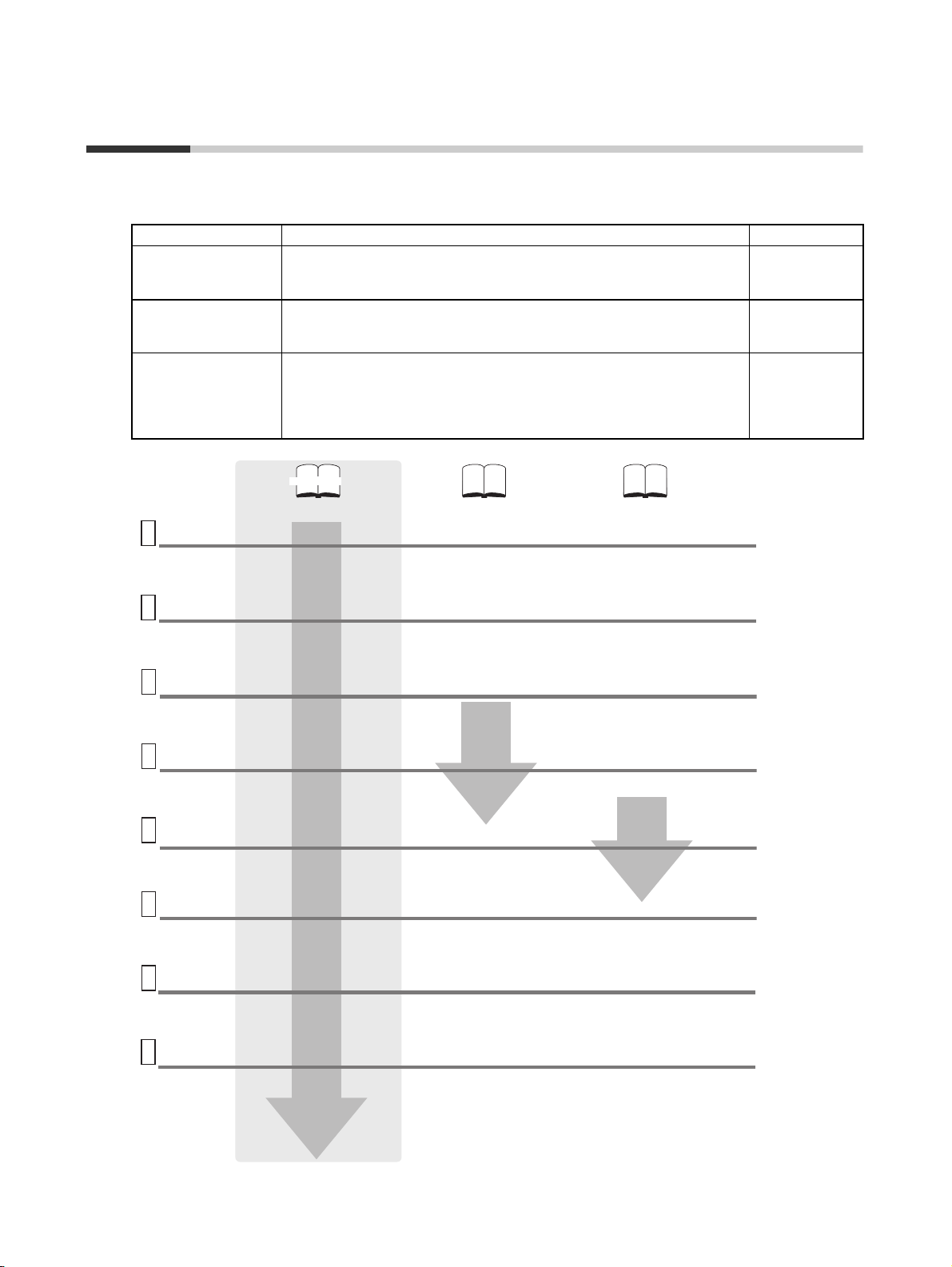
Manual name Contents Cat. No.
G9SP-series Safety
Controller Operation
Manual (this manual)
G9SP-series Safety
Controller Instructio ns
Reference Manual
G9SP-series Safety
Controller Host Connection Manual
System
configuration
1
settings
• Unit type, nomenclature, and specifications
• Configuring hardware
• Calculating safety response performance
Installation
2
and Wiring
• Precautions for installation in a panel
• Performing power supply wiring
Support
Software
3
Startup
Software
settings and
4
programming
Control
PLC
5
Design
Checking
and
debugging
6
operation
Operation
and
7
Maintenance
• Performing I/O wiring
• Installing the Support Software (G9SP
• Starting the Support Software
• Creating configuration data in the
• Setting the control PLC to
• Downloading configuration data to the
• Checking operation using the Support
• Replacement at G9SP failure
• Updating the configuration data in the
This manual provides detailed specifications and describes functions
and application methods for the G9SP-series Controller in detail.
This manual describes the safety programming methods, provides the
specifications, and describes the functions and operating methods of the
G9SP-series Controllers.
This manual provides sample ladder programming and describes how to
connect to a Standard PLC from another manufacturer using the communications functionality of the G9SP-series Controller's Option Board.
The procedure for connecting to a Standard PLC from another manufacturer is described in the G9SP Operation Manual.
This manual
G9SP-series Safety Controller
Operation Manual
(Cat. No. Z922)
Configurator)
Support Software
communicate with the G9SP
G9SP
Software
G9SP
G9SP-series Safety Controller Instructions
Reference Manual
(Cat. No. Z923)
• Safety logic programming
• Function block operation specifications
G9SP-series Safety Controller
Host Connection Manual
(Cat. No. Z924)
Note: Provided only as a PDF file.
• Sample ladder programming for the
control PLC
Z922
Z923
Z924
8
Troubleshooting
• Corrective measures and error codes
for troubleshooting
x

Sections in this Manual
Overview
1
Part Names and
2
Specifications
Calculating Response
3
Performance
Installation and Wiring
4
Preparations for Using
5
the G9SP Configurator
Creating Configuration Data
6
Checking Operating
10
Status and Debugging
Backup and Restore Data
11
Using Memory Cassette
Maintenance and
12
Inspections
Troubleshooting
13
Application Templates
A
Communications with a Standard PLC Using
7
an Option Board
Connecting Online and Downloading to the
8
G9SP-series Controller
Operation and Operating Modes
9
xi

xii

Terms and Conditions Agreement
Warranty, Limitations of Liability
Warranties
● Exclusive Warranty Omron’s exclusive warranty is that the Products will be free from defects in
materials and workmanship for a period of twelve months from the date of
sale by Omron (or such other period expressed in writing by Omron). Omron
disclaims all other warranties, express or implied.
● Limitations OMRON MAKES NO WARRANTY OR REPRESENTATION, EXPRESS OR
IMPLIED, ABOUT NON-INFRINGEMENT, MERCHANTABILITY OR FITNESS FOR A PARTICULAR PURPOSE OF THE PRODUCTS. BUYER
ACKNOWLEDGES THAT IT ALONE HAS DETERMINED THAT THE PRODUCTS WILL SUITABLY MEET THE REQUIREMENTS OF THEIR INTENDED
USE.
Omron further disclaims all warranties and responsibility of any type for claims
or expenses based on infringement by the Products or otherwise of any intellectual property right.
● Buyer Remedy Omron’s sole obligation hereunder shall be, at Omron’s election, to (i) replace
(in the form originally shipped with Buyer responsible for labor charges for
removal or replacement thereof) the non-complying Product, (ii) repair the
non-complying Product, or (iii) repay or credit Buyer an amount equal to the
purchase price of the non-complying Product; provided that in no event shall
Omron be responsible for warranty, repair, indemnity or any other claims or
expenses regarding the Products unless Omron’s analysis confirms that the
Products were properly handled, stored, installed and maintained and not
subject to contamination, abuse, misuse or inappropriate modification. Return
of any Products by Buyer must be approved in writing by Omron before shipment. Omron Companies shall not be liable for the suitability or unsuitability or
the results from the use of Products in combination with any electrical or electronic components, circuits, system assemblies or any other materials or substances or environments. Any advice, recommendations or information given
orally or in writing, are not to be construed as an amendment or addition to
the above warranty.
Limitation on
Liability; Etc
See http://www.omron.com/global/ or contact your Omron representative for
published information.
OMRON COMPANIES SHALL NOT BE LIABLE FOR SPECIAL, INDIRECT,
INCIDENTAL, OR CONSEQUENTIAL DAMAGES, LOSS OF PROFITS OR
PRODUCTION OR COMMERCIAL LOSS IN ANY WAY CONNECTED WITH
THE PRODUCTS, WHETHER SUCH CLAIM IS BASED IN CONTRACT,
WARRANTY, NEGLIGENCE OR STRICT LIABILITY.
Further, in no event shall liability of Omron Companies exceed the individual
price of the Product on which liability is asserted.
xiii

Application Considerations
Suitability of Use Omron Companies shall not be responsible for conformity with any standards,
codes or regulations which apply to the combination of the Product in the
Buyer’s application or use of the Product. At Buyer’s request, Omron will provide applicable third party certification documents identifying ratings and limitations of use which apply to the Product. This information by itself is not
sufficient for a complete determination of the suitability of the Product in combination with the end product, machine, system, or other application or use.
Buyer shall be solely responsible for determining appropriateness of
the particular Product with respect to Buyer’s application, product or system.
Buyer shall take application responsibility in all cases.
NEVER USE THE PRODUCT FOR AN APPLICATION INVOLVING SERIOUS
RISK TO LIFE OR PROPERTY WITHOUT ENSURING THAT THE SYSTEM
AS A WHOLE HAS BEEN DESIGNED TO ADDRESS THE RISKS, AND
THAT THE OMRON PRODUCT(S) IS PROPERLY RATED AND INSTALLED
FOR THE INTENDED USE WITHIN THE OVERALL EQUIPMENT OR SYSTEM.
Programmable
Products
Omron Companies shall not be responsible for the user’s programming of a
programmable Product, or any consequence thereof.
Disclaimers
Performance Data Data presented in Omron Company websites, catalogs and other materials is
provided as a guide for the user in determining suitability and does not constitute a warranty. It may represent the result of Omron’s test conditions, and the
user must correlate it to actual application requirements. Actual performance
is subject to the Omron’s Warranty and Limitations of Liability.
Change in
Specifications
Errors and Omissions Information presented by Omron Companies has been checked and is
Product specifications and accessories may be changed at any time based on
improvements and other reasons. It is our practice to change part numbers
when published ratings or features are changed, or when significant construction changes are made. However, some specifications of the Product may be
changed without any notice. When in doubt, special part numbers may be
assigned to fix or establish key specifications for your application. Please consult with your Omron’s representative at any time to confirm actual specifications of purchased Product.
believed to be accurate; however, no responsibility is assumed for clerical,
typographical or proofreading errors or omissions.
xiv
Safety Precautions
Definition of Precautionary Information
The following notation is used in this manual to provide precautions required to ensure safe usage of a
G9SP-series Controller. The safety precautions that are provided are extremely important to safety.
Always read and heed the information provided in all safety precautions.
The keywords and their definitions are as given below.
Indicates a potentially hazardous situation which, if not avoided,
WARNING
will result in minor or moderate injury, or may result in serious
injury or death. Additionally there may be significant property
damage.
Indicates precautions on what to do and what not to do to ensure using the product safely.
Indicates precautions on what to do and what not to do to ensure proper operation and performance.
Symbols
Caution
Precautions for Safe Use
Precautions for Correct Use
The circle and slash symbol indicates operations that you must not do.
The specific operation is shown in the circle and explained in text.
Indicates a potentially hazardous situation which, if not avoided,
may result in minor or moderate injury or in property damage.
The filled circle symbol indicates operations that you must do. The
specific operation is shown in the circle and explained in text. This
example shows a general precaution for something that you must do.
xv

WARNING
This is the Operation Manual for the G9SP-series Safety Controllers.
Obey the following warnings during system construction to ensure that safety-related components are configured to
enable the system functions to sufficiently operate.
● Risk Assessment
The proper use of the safety devices described in this manual as they relate to installation conditions and mechanical
performance and functions is a prerequisite for its use.
When selecting or using the safety devices, risk assessment must be performed during the development stage of the
equipment or facilities to identify potential danger factors in equipment or facilities in which the safety devices are to be
applied. Suitable safety devices must be selected under the guidance of a sufficient risk assessment system. An insufficient risk assessment system may result in the selection of unsuitable safety devices.
• Typical related international standards: ISO 14121, Safety of Machinery -- Principles of Risk Assessment
● Safety Measures
When using this safety device to build systems containing safety-related components for equipment or facilities, the
system must be designed with the full understanding of and conformance to international standards, such as those
listed below, and/or standards in related industries.
• Typical related international standards: ISO/DIS 12100, Safety of Machinery -- Basic Concepts and General
Principles for Design
IEC 61508, Safety Standard for Safety Instrumented Systems (Functional Safety of Electrical/Electronic/Programmable Electronic Safety-related Systems)
● Role of Safety Devices
The safety devices are provided with safety functions and mechanisms as stipulated in relevant standards, but suitable
designs must be used to enable these functions and mechanisms to operate properly inside system constructions containing safety-related components. Build systems that enable these functions and mechanisms to perform properly,
based on a full understanding of their operation.
• Typical related international standards: ISO 14119, Safety of machinery -- Interlocking devices associated with
guards -- Principles for design and selection
● Installation of Safety Devices
The construction and installation of systems with safety-related components for equipment or facilities must be performed by technicians who have received suitable training.
• Typical related international standards: ISO/DIS 12100, Safety of Machinery -- Basic Concepts and General
Principles for Design
IEC 61508, Safety Standard for Safety Instrumented Systems (Functional Safety of Electrical/Electronic/Programmable Electronic Safety-related Systems)
● Compliance with Laws and Regulations
This safety device conforms to the relevant regulations and standards, but make sure that it is used in compliance with
local regulations and standards for the equipment or facilities in which it is applied.
• Typical related international standards: IEC 60204, Safety of Machinery -- Electrical Equipment of Machines
● Observing Precautions for Use
When putting the selected safety device to actual use, heed the specifications and precautions in this manual and
those in the instruction manual that comes with the product. Using a product in a manner that deviates from these
specifications and precautions will lead to unexpected failures in equipment or devices, and to damage that results
from such failures, due to insufficient operating functions in safety-related components.
● Moving or Transferring Devices or Equipment
When moving or transferring devices or equipment, be sure to include this manual to ensure that the person to whom
the device or equipment is being moved or transferred will be able to operate it properly.
• Typical related international standards: ISO/DIS 12100, Safety of Machinery -- Basic Concepts and General
Principles for Design
IEC 61508, Safety Standard for Safety Instrumented Systems (Functional Safety of Electrical/Electronic/Programmable Electronic Safety-related Systems)
xvi
WARNING
Electric shock may occur. Do not touch any terminals while power is being supplied.
Serious injury may possibly occur due to loss of required safety functions. Do not use the
G9SP-series Controller's test outputs or standard outputs as safety outputs.
Serious injury may possibly occur due to loss of required safety functions. Do not use the
G9SP-series Controller's network data as safety data.
Serious injury may possibly occur due to loss of required safety functions. Do not use indicators on the G9SP-series Controller for safety operations.
Serious injury may possibly occur due to breakdown of safety outputs or test outputs. Do not
connect loads beyond the rated values to the safety outputs and test outputs.
Serious injury may possibly occur due to loss of required safety functions. Wire the G9SPseries Controller properly so that the 24VDC line does NOT touch the outputs accidentally or
unintentionally.
Serious injury may possibly occur due to loss of required safety functions. Ground the 0V line
of the power supply for external output devices so that the devices do NOT turn ON when the
safety output line or the test output line is grounded.
Serious injury may possibly occur due to loss of required safety functions. Perform user testing
and confirm that all of the G9SP-series Controller’s configuration data and operation is correct
before starting system operation.
Serious injury may possibly occur due to loss of required safety functions. When replacing a
G9SP-series Controller, confirm the model of the Controller is correct and configure the
replacement Controller suitably and confirm that it operates correctly.
Serious injury may possibly occur due to loss of required safety functions. Once the data has
been restored from the Memory Cassette, check that the configuration data of the G9SP-series
Controller is correct in that it operates properly and carry out the validation testing (User Testing).
Outputs may operate, possibly resulting in serious injury. Take sufficient safety measures
before force-setting or force-resetting variables in the program.
Serious injury may possibly occur due to loss of required safety functions. Use devices and
parts related to safety functions according to legal regulations in the applicable country. Use
certified items compliant with safety standards corresponding to the intended application.
xvii
Precautions for Safe Use
● Handling
Do not drop the G9SP-series Controller or subject it to excessive vibration or mechanical shock. The
G9SP-series Controller may be damaged and may not function properly.
● Installation and Storage Environment
Do not use or store the G9SP-series Controller in any of the following locations:
• Locations subject to direct sunlight
• Locations subject to temperatures or humidity outside the range specified in the
specifications
• Locations subject to condensation as the result of severe changes in temperature
• Locations subject to corrosive or flammable gases
• Locations subject to dust (especially iron dust) or salts
• Locations subject to water, oil, or chemicals
• Locations subject to shock or vibration
Take appropriate and sufficient measures when installing systems in the following locations. Inappropriate and insufficient measures may result in malfunction.
• Locations subject to static electricity or other forms of noise
• Locations subject to strong electromagnetic fields
• Locations subject to possible exposure to radioactivity
• Locations close to power supplies
This is a class A product designed for use in industrial environments. In residential areas it may cause
radio interference, in which case the user may be required to take adequate measures to reduce interference.
● Installation and Mounting
• Use the G9SP-series Controller within an enclosure with IP54 protection or higher according to IEC/
EN 60529.
• Use DIN Track (TH35-7.5/TH35-15 according to IEC 60715) or M4 screws with a tightening torque of
1.2 N·m (10.5 lb·in) to install the G9SP-series Controller into the control panel.
• Mount the G9SP-series Controller to the DIN Track using PFP-M End Plates (not included with the
G9SP-series Controller) to prevent it from falling off the DIN Track because of vibration. Correctly
mount all Units to DIN Track.
• Install the G9SP-series Controller in the vertical direction shown below to ensure adequate cooling.
• Space must be provided around the G9SP-series Controller, at least 20 mm from its side surfaces and
at least 50 mm from its top and bottom surfaces, for ventilation, wiring and Unit replacement.
• Be sure to lock all locking mechanisms, such as those on I/O terminal blocks and connectors, before
attempting to use the G9SP-series Controller.
xviii
Turn OFF the power supply before performing any of the following.
• Connecting or disconnecting Expansion I/O Units, Option Boards, or any other Units
• Assembling the G9SP-series Controller
• Connecting cables or wiring
• Connecting or removing terminal blocks
● Installation and Wiring
• Use the following to wire external I/O devices to the G9SP-series Controller.
Solid wire
Stranded wire
0.32 to 0.82 mm
0.32 to 0.5 mm
0.5 to 1.3 mm
0.5 to 0.82 mm
*1: When wiring two wires to one terminal. Use two wires of the same type and thickness.
• M3 self-rising screws are used for all screw terminals.
• Tighten the terminal block screws to a torque of 0.5 N·m (4.4 lb·in).
• Disconnect the G9SP-series Controller from the power supply before starting wiring. Devices connected to the G9SP-series Controller may operate unexpectedly.
• Properly apply the specified voltage to the G9SP-series Controller inputs. Applying an inappropriate
DC voltage or any AC voltage will cause the G9SP-series Controller to fail.
• Be sure to separate the communications cables and I/O cables from high-voltage/high-current lines.
• Be cautious not to get your fingers caught when attaching connectors to the plugs on the G9SP-series
Controller.
• Incorrect wiring may lead to loss of safety functions. Wire conductors correctly and verify the operation
of the G9SP-series Controller before using the system in which the G9SP-series Controller is incorporated.
• Lock the connectors on Option Units or Expansion I/O Units before using the Units.
• After wiring is completed, be sure to remove the label for wire clip entry prevention from the G9SPseries Controller to enable heat to escape for proper cooling.
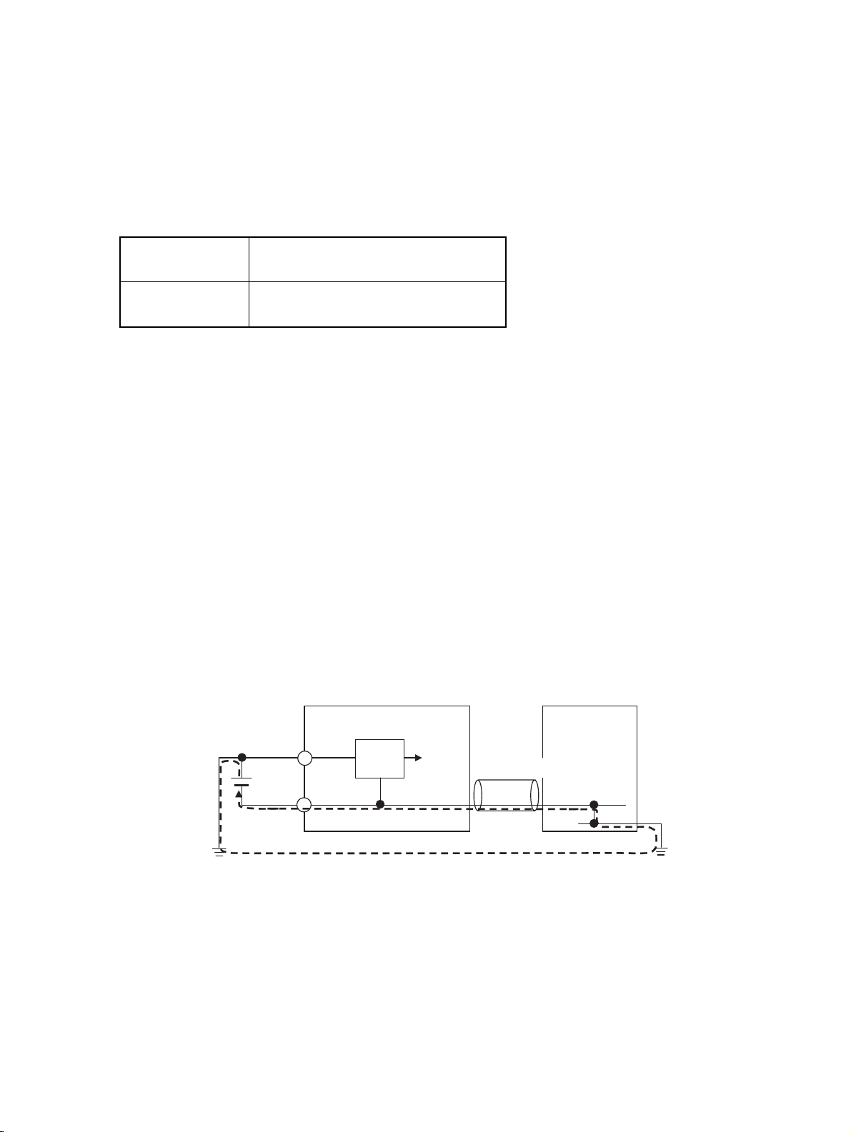
• Do not ground the 24-V side of the power supply to the G9SP-series Controller. If you do so, an
unwanted current flow shown in the following diagram may occur when you connect a computer or
other peripheral device.
2
AWG22 to AWG18
2
AWG22 to AWG20*1
2
AWG20 to AWG16
2
AWG20 to AWG18*1
G9SP
Peripheral device
Power supply circuit
24 V
USB cable
GND
0 V
0 V
• Connect no more than the specified number of Expansion I/O Units.
0 V
FG
xix

● Power Supply Selection
Use a DC power supply satisfying the following requirements.
• The secondary circuit of the DC power supply must be isolated from the primary circuit by double insulation or reinforced insulation.
• The output characteristic requirements defined in UL 508 for class 2 circuits or control voltage current circuits are satisfied.
• The output hold time must be 20 ms or longer.
• The DC power supply must be an SELV power supply that satisfies the requirements
of IEC/EN 60950-1 and EN 50178.
● Periodic Inspections and Maintenance
• Disconnect the G9SP-series Controller from the power supply before replacing the Controller. Devices
connected to the G9SP-series Controller may operate unexpectedly.
• Do not disassemble, repair, or modify the G9SP-series Controller. Doing so may lead to loss of safety
functions.
● Disposal
Be cautious not to injure yourself when dismantling the G9SP-series Controller.
xx
Precautions for Compliance with UL
Standards and CSA Standards
Use the following installation information instead of the general information in the instruction manual in
order to use the product under certified conditions of UL and CSA when the product is installed in the
USA or Canada. These conditions are required by NFPA 70 (National Electrical Code in the USA) and
Part 1 of the Canadian Electrical Code in Canada and may vary from information given in the product
manuals or safety precautions. G9SP-series Controllers have not been evaluated by UL as Programmable Safety Controllers, and the Safety functions of these devices have not been evaluated by UL as well.
• Surrounding air temperature: 55°C
• Do not use crimp terminals for field wiring.
• The DC power supply must satisfy the requirements for an isolated power supply
with external 8 A overcurrent protection.
• Do not use the +5 V output from the CP1W-CIF01 for anything other than the NTAL001.
• A G9SP-series Controller has two sets of power supply terminals, one for the main
power and one for I/O power. Connect both of them to the same power source.
● Ratings
Controller Rating for UL
G9SP-N20S Source: 24 V dc, 500 mA, isolated source
Input: 24 V dc, 6 mA /P, 20 points
Output: 24 V dc (GEN) (P.D.), 0.8 A /P, 8 points
Rated total currents of So0 to 3, So4 to 7 are 1.6 A each
Test Output:
T0 − T2: 24 V dc (GEN), 100 mA
T3: 24 V dc (GEN)(TUN), 300 mA
T4, T5: 24 V dc (GEN), 30 mA
Rated total currents of T0 − T2, T4 and T5 are 120 mA
G9SP-N10D Source: 24 V dc, 500 mA, isolated source
Input: 24 V dc, 6 mA, 10 points
Output: 24 V dc (GEN) (P.D.), 0.8 A /P, 16 points
Rated total currents of So0 to 3, So4 to 7, So8 to 11, So12 to So15 are 1.2 A each
Test Output:
T0 − T2: 24 V dc (GEN), 60 mA
T3: 24 V dc (GEN)(TUN), 300 mA
T4, T5: 24 V dc (GEN), 30 mA
Rated total currents of T0 − T2, T4 and T5 are 60 mA
G9SP-N10S Source: 24 V dc, 400 mA, isolated source
Input: 24 V dc, 6 mA /P, 10 points
Output: 24 V dc (GEN) (P.D.), 0.8 A /P, 1.6 A /Unit, 4 points
Test Output:
T0, T1: 24 V dc (GEN), 60 mA
T2: 24 V dc (GEN), 30 mA
T3: 24 V dc (GEN)(TUN), 300 mA
Rated total currents of T0 − T2 are 60 mA
Standard Output: 24 V dc (GEN), 100 mA, 4 points
● TERMINAL MARKINGS
Terminals Function
V1/G1 Power supply terminals for Internal/Input circuits (24 VDC).
V2/G2 Power supply terminals for output circuits (24 VDC).
NC Not used (Do not connect)
Si0 to Si19 Input terminals
T0 to T5 Test output terminals
So0 to So15 Output terminals
O0 to O3 Standard output terminals
xxi
Regulations and Standards
The G9SP-series Controller has obtained certification for the following standards.
Certifying body Standards
TÜV Rheinland • EN ISO 13849-1:2015
• EN ISO 13849-2:2012
• IEC 61508 parts 1-7:2010
• EN 62061:2005+A1:2013+A2:2015
• IEC 61131-2:2007
• EN ISO 13850:2015
UL • UL508 • CSA22.2 No.142
KOSHA
Others • CE Marking
*1 The G9SP-series Controller (version 1.1 or later) and the Expansion I/O Units have been certified for
the KOSHA S Mark.
Using a G9SP-series Controller enables building a safety control system that satisfy the following:
•S Mark
• C-Tick mark
• Requirements for SIL 3 (Safety Integrity Level 3) in IEC 61508, IEC/EN 62061,
Safety Standard for Safety Instrumented Systems (Functional Safety of Electrical/
Electronic/Programmable Electronic Safety-related Systems)
• Requirements for PLe (Performance Level e) and for safety category 4 in EN
ISO13849-1
*1
• EN 60204-1:2006+A1:2009
• EN 61000-6-2:2005
• EN 61000-6-4:2007+A1:2011
• NFPA 79-2015
• ANSI RIA 15.06-2012
• ANSI B11.19-2010
• ANSI/UL 1998:2013
Compliance with EC Directives
Applicable Directives
• EMC Directive (2014/30/EU)
• Machinery Directive (2006/42/EC)
Concepts
● EMC Directive
OMRON electrical devices are built into other components or equipment. OMRON therefore pursues
compliance with the related EMC standards so that they can be more easily built into other devices or
the equipment.*
OMRON cannot confirm compliance in the customer's actual application, however, because the customer may use a variety of components and equipment, and EMC performance depends on the configuration, wiring, and arrangement of the equipment and control panel into which a product applicable to
EC Directives is incorporated. Therefore, whether the products conform to the standards in the system
used by the customer must be checked by the customer.
* Applicable EMC (Electromagnetic Compatibility) standards are as follows: EN
61000-6-2 for EMS (Electromagnetic Susceptibility) and EN 61000-6-4 for Electromagnetic Interference (10-m regulations applied for EN 61000-6-4 radiated emission).
xxii

● Machinery Directive
The Machinery Directive requires ensuring the required safety for safety components used for machinery safety.
Applicable standards: EN ISO 13849-1:2015 and IEC/EN 62061 SIL CL3
● Conformance to EC Directives
The G9SP-series Controller complies with EC Directives. To ensure that the machine or device in which
the G9SP-series Controller is used complies with EC Directives, the following requirements must be
met.
• Make sure that the DC power supply connected to a DC Power Supply Unit or I/O
Unit satisfies the following conditions.
• There is double insulation or reinforced insulation between the primary circuit and secondary circuit.
• An isolated power supply that is limited to a current of 8 A or lower must be
used.
• The output hold time is 20 ms min.
• The power supply is a SELV power supply that satisfies requirements in IEC/
EN 60950-1 and EN 50178.
• G9SP-series products that comply with the EC Directives also comply with the
Generic Emission Standard (EN 61000-6-4) for EMI. The radiated emission characteristics (10-m regulations), however, may depend on the configuration of the control
panel that is used and the relation to and wiring with other connected devices. Even
through the G9SP-series Controller complies with EC Directives, the customer must
confirm that the overall machinery and equipment in which the G9SP-series Controller is used complies with the EC Directives.
EN ISO 13849-1 and IEC/EN 62061 Compliance
EN ISO 13849-1 and IEC/EN 62061 require process management to avoid system interference and to
simplify reading, understanding, testing, and maintaining software. This is required in all phases of the
life cycle of software programming and software design (e.g., basic software design, safety circuit system design, and software upgrades) in safety control systems to be developed using safety controllers.
Therefore, process management is required for design and development of software for facilities and
equipment that use the function blocks provided in the Safety Controller.
The customer must implement measures to ensure compliance with these standards.
To obtain the reliability data for safety of machinery to verify the safety performance of your equipment,
go to the following URL: http://www.ia.omron.com/support/sistemalibrary/index.html.
xxiii

Glossary
The following terms are used in this manual to describe the function blocks of the G9SP-series Safety
Controllers.
Terminology
Term Definition
Safety Describes a device, function, data, or other element for which special safety measures
have been implemented for use in Safety Controls.
Standard Describes a device, function, data, or other element that is used in Standard Controls.
Used to differentiate from devices, functions, data, or other elements for which special
safety measures have been implemented for use in Safety Controls.
Safety Controller A highly reliable controller that is used in Safety Controls.
Standard PLC A programmable controller (PLC) that is used for general controls.
Used to differentiate from a PLC used for Safety Controls.
Expansion I/O Unit The name of the CP1W-20EDT(-1) and CP1W-32ET(-1).
Some of the OMRON CP1-series Expansion I/O Units can be used in a G9SP-series
Controller. Expansion I/O Units are connected to a G9SP-series Controller to increase
the number of Standard I/O points.
Option Board The name of the CP1W-CIF01 and CP1W-CIF41.
Some of the OMRON CP1-series Option Boards can be used in a G9SP-series Control-
ler. An Option Board can be mounted in a G9SP-series Controller to communicate with a
Standard PLC.
Memory Cassette The name of the CP1W-ME05M.
This OMRON CP1@-series Memory Cassette can be used in a G9SP-series Controller. It
is used to back up and restore configuration data in G9SP-series Controllers.
G9SP Configurator The name of the WS02-G9SP@@.
Support Software that is used to set up, program, and debug G9SP-series Controllers.
configuration data Setup data that is used to operate a G9SP-series Controller. The configuration data is
created with the G9SP Configurator and then downloaded from the computer to memory
in the G9SP-series Controller. The configuration data contains the unit configuration set-
tings, I/O terminal settings, system settings, and Safety Program. Refer to SECTION 6
Creating Configuration Data for details.
backup An operation used to write the configuration data stored in internal memory in the G9SP-
series Controller to a Memory Cassette.
restore An operation used to write the configuration data stored in a Memory Cassette to internal
memory in the G9SP-series Controller.
Safety Input Device An input device for which special safety measures have been implemented for use in
Safety Controls. Safety Input Device is therefore a generic term for input devices such as
emergency stop switches and safety door switches.
Safety Output Device An output device for which special safety measures have been implemented for use in
Safety Controls. Safety Output Device is therefore a generic term for output devices such
as safety relays.
CP Series A series of programmable controllers manufactured by OMRON.
NE1A Series A series of Safety Network Controllers manufactured by OMRON. NE1A-series Control-
lers are high-end controllers in comparison to the G9SP-series Controllers.
dual channels Two channels that are used for redundancy with Safety Inputs or Safety Outputs. If the
two channels must have the same value, they are called equivalent dual channels. If they
must have the opposite values, they are called complementary dual channels.
discrepancy The state in which the status of two dual channels do not agree, resulting in a discrep-
ancy error.
xxiv
Acronyms
Acronym Meaning
MC Memory Cassette.
Si Safety Input.
An input from a Safety Input terminal. This term is used to differentiate from a
Standard Input (IN).
So Safety Output.
An output from a Safety Output terminal. This term is used to differentiate from
a Standard Output (OUT).
To Test Ou t p u t .
An output from a Test Output terminal used to diagnose a Safety Input terminal
by outputting a test pulse.
xxv

xxvi

Overview
SECTION 1
Overview
This section provides an overview and describes the features, system configuration, and application procedures for the
G9SP-series Controller.
1-1 Overview and Features of the G9SP-series Controller . . . . . . . . . . . . . . . . . . 2
1-1-1 Overview. . . . . . . . . . . . . . . . . . . . . . . . . . . . . . . . . . . . . . . . . . . . . . 2
1-1-2 Basic System and Configuration Devices. . . . . . . . . . . . . . . . . . . . . 2
1-1-3 Features. . . . . . . . . . . . . . . . . . . . . . . . . . . . . . . . . . . . . . . . . . . . . . . 5
1-2 Basic Operating Procedures . . . . . . . . . . . . . . . . . . . . . . . . . . . . . . . . . . . . . . 9
1
Overview and Features of the G9SP-series Controller Section 1-1
1-1 Overview and Features of the G9SP-series Controller
1-1-1 Overview
The G9SP-series Safety Controller is a programmable controller that is
designed for easy operation in small to mid-sized Safety Control systems.
Using the G9SP-series Safety Controller enables building Safety Control systems that satisfy the requirements for SIL 3 (Safety Integrity Level 3) in IEC
61508 (Safety Standard for Safety Instrumented Systems: Functional Safety
of Electrical/Electronic/Programmable Electronic Safety-related Systems) and
IEC/EN 62061 (Safety of Machinery -- Functional Safety of Safety-related
Electrical, Electronic and Programmable Electronic Control Systems), as well
as safety category 4 and PLe (Performance Level e) in EN ISO 13849-1.
The use of Expansion I/O Units and optional products enables a wide variety
of applications.
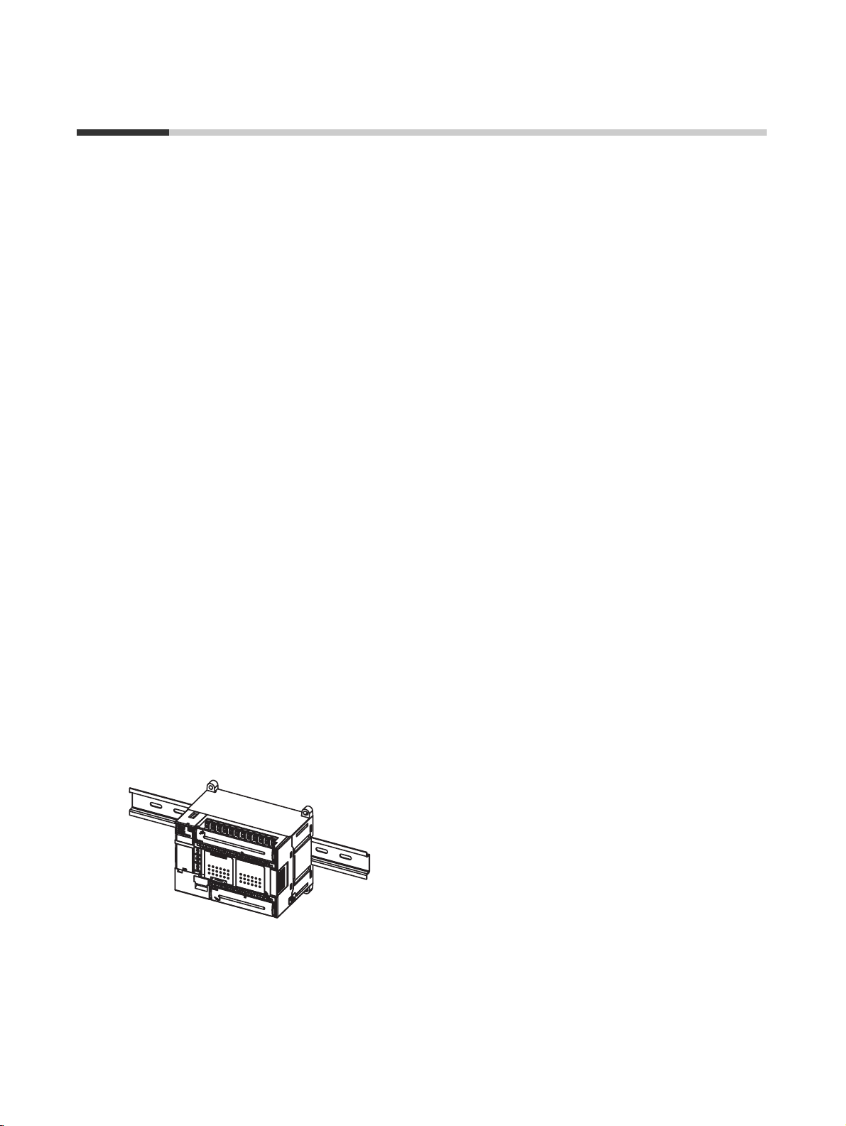
1-1-2 Basic System and Configuration Devices
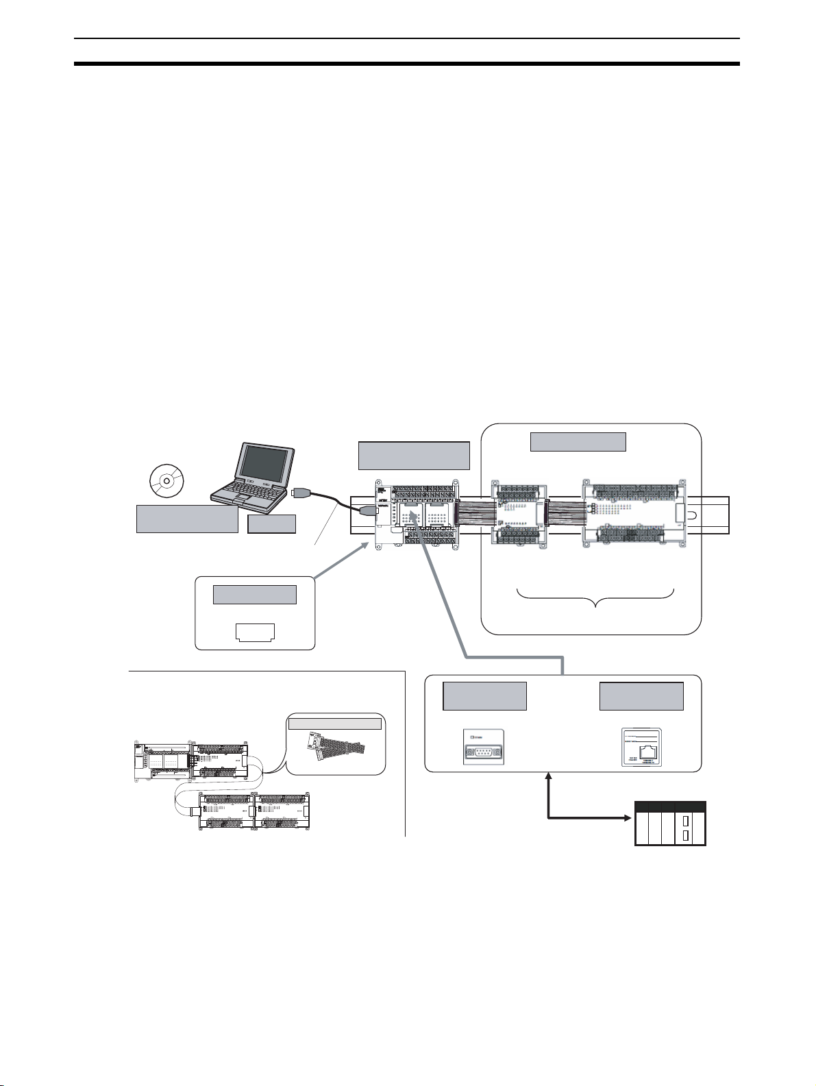
This section describes the basic system configuration for a G9SP-series Controller.
G9SP Configurator
Support Software
WS02-G9SP@@@
When distance is required between the Units, for example,
when a two-level layout is created using Expansion I/O Units.
G9SP-series
Controller
Computer
USB cable
G9SP-N@@@
Memory Cassette
CP1W-ME05M
MEMORY
I/O Connecting Cable
CP1W-CN811
Expansion I/O Units
G9SP-series
Safety Controller
RS-232C or
Ethernet communications
Expansion I/O Units
CP1W-20EDT/EDT1
CP1W-32ET/ET1
The G9SP-series Safety Controller can be
expanded using up to two Expansion I/O Units.
RS-232C
Option Board
CP1W-CIF01
CP1W-CIF41 (unit version 2.0 or later)
Or
Ethernet
Option Board
Standard PLC
2
Overview and Features of the G9SP-series Controller Section 1-1
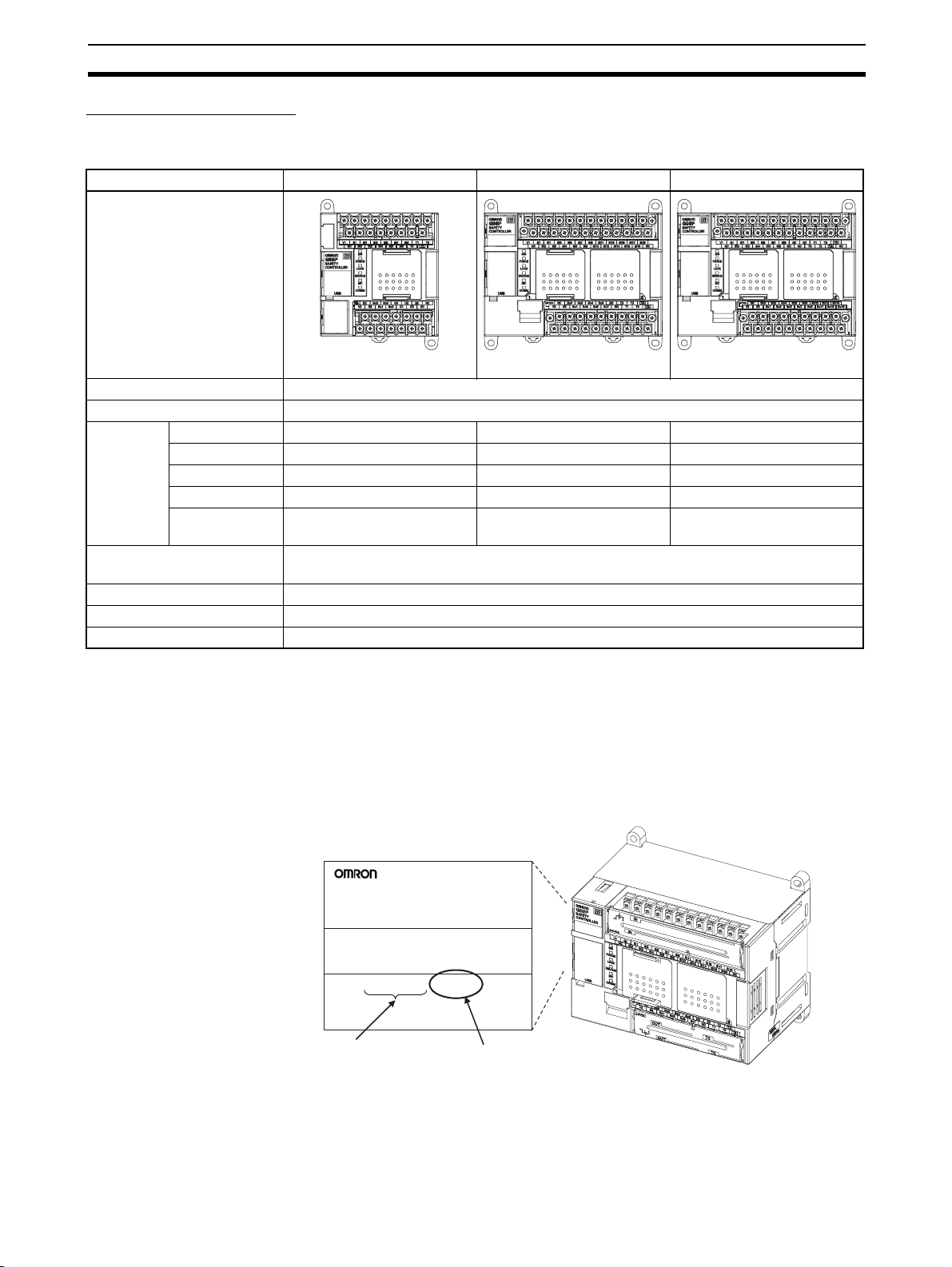
G9SP-series Controller
There are three models of G9SP-series Controllers depending on the number
of Safety I/O points.
Name/model G9SP-N10S G9SP-N10D G9SP-N20S
Appearance
W66 x H110 x D65 (mm) W130 x H110 x D85 (mm) W130 x H110 x D85 (mm)
Power supply 24 VDC
Program size Function blocks: 128 max.
Number of
I/O points
Expansion using Expansion
I/O Units
Mounting Option Boards One Option Board can be mounted.
Using Memory Cassettes Supported
Mounting a battery Not supported
Safety Inputs 10 points 10 points 20 points
Safety Outputs 4 semiconductor outputs 16 semiconductor outputs 8 semiconductor outputs
Test Outputs 4 points 6 points 6 points
Standard Inputs None None None
Standard Out-
4 semiconductor outputs None None
puts
Up to 2 Expansion I/O Units can be mounted.
Unit Versions of G9SP-series Controller
A “unit version” has been introduced to manage G9SP-series Controllers
according to differences in functionality accompanying Controller upgrades.
• Notation of Unit Versions on Products
Product nameplate
G9SP
SAFETY
CONTROLLER
Lot No. 28705 0000 Ver.1.0
OMRON Corporation MADE IN CHINA
Lot No.
• Confirming Unit Versions with the G9SP Configurator (version 1.10 or
higher)
The unit version is given to the right of the lot number on the nameplate
of the products for which unit versions are being managed, as shown
below.
G9SP-series
Safety Controller
Unit version
(example for unit version 1.0)
3
Overview and Features of the G9SP-series Controller Section 1-1
You can check the unit version by right-clicking the unit name in the
Project Window and selecting Properties from the G9SP Configura-
tor.
■ Unit Versions
The information provided in this manual applies to all unit versions unless otherwise specified.
Model Model numbers Unit version
G9SP-series Controller G9SP-N@@@ Unit version 1.0
Unit version 1.1
Unit version 2.0
Unit version 1.1 or later is certified for the KOSHA S Mark.
Expansion I/O Units
The following four models of CP-series Expansion I/O Units can be used.
The CP1W-CN811 I/O Connecting Cable can also be used.
Name/model Unit with 20 Standard I/O points Unit with 32 Standard I/O points
CP1W-20EDT CP1W-20EDT1 CP1W-32ET CP1W-32ET1
Appearance
COM 01 03 05 07 09 11
NC 00 02 04 06 08 10
CH
IN
CH
00 01 02 03
04 05 06 07
08 09 10 11
OUT
CH
00 01 02 03 04 05 06 07
CH
NC 00 01 02 04 05 07
NC COM COM COM 03 COM 06
EXP
NCNCNC
COM
01 03 05 07 09 11 01 03 05 07 09 11
NC
00 02 04 06 08 10
CH CH
CH
IN
CH
CH
0706050403020100
OUT
CH
0706050403020100
CH CH
NC
00 01 02 04 05 07 00 02 04 05 07
NC
COM COM COM COM COM COM03 06 01 03 06
111009080706050403020100
111009080706050403020100
00 02 04 06 08 10
EXP
W86 x H110 x D50 (mm) W150 x H110 x D50 (mm)
Number of I/O
points
Standard Inputs 12 points None
Standard Outputs 8 semiconductor
outputs (sinking)
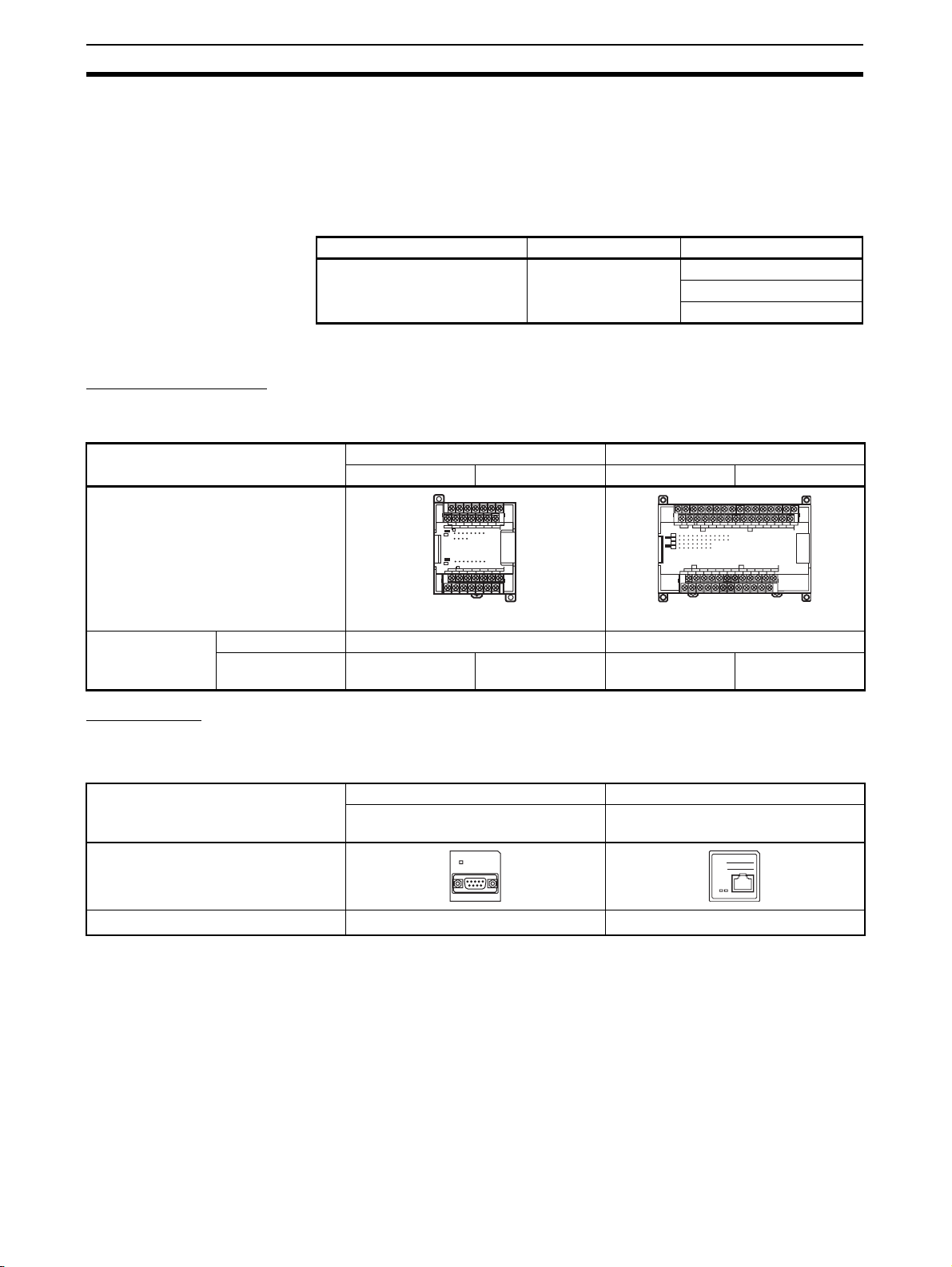
Option Units
Option Boards
The following two models of CP-series Option Boards can be used.
Name/model RS-232C Option Board Ethernet Option Board
Appearance
Protocol No-protocol
*1 Communications with an OMRON Standard PLC can be performed using
FINS/UDP.
Memory Cassette
The CP1W-ME05M CP-series Memory Cassette can be used.
8 semiconductor
outputs (sourcing)
32 semiconductor
outputs (sinking)
32 semiconductor
outputs (sourcing)
CP1W-CIF01 CP1W-CIF41
(unit version 2.0 or later)
COMM
*1
UDP/IP
IP ADDRESS:
SUBNET MASK:
COMMERR
10BASE-T
100BASE-TX
4
 Loading...