

Page 1

Cat. No. Z922-E1-07
G9SP Series
Safety Controller
OPERATION M ANUAL
Page 2

NOTE
All rights reserved. No part of this publication may be reproduced, stored in a retrieval system, or transmitted, in
any form, or by any means, mechanical, electronic, photocopying, recording, or otherwise, without the prior
written permission of OMRON.
No patent liability is assumed with respect to the use of the information contained herein. Moreover, because
OMRON is constantly striving to improve its high-quality products, the information contained in this manual is
subject to change without notice. Every precaution has been taken in the preparation of this manual. Nevertheless, OMRON assumes no responsibility for errors or omissions. Neither is any liability assumed for damages
resulting from the use of the information contained in this publication.
Trademarks
• Microsoft, Windows, and Windows Vista are either registered trademarks or trademarks of Microsoft Corporation
in the United States and other countries.
Other company names and product names in this document are the trademarks or registered trademarks of their
respective companies.
Copyrights
Microsoft product screen shots reprinted with permission from Microsoft Corporation.
Page 3

G9SP-series Safety Controller:
G9SP-N@@@
Operation Manual
Revised December 2016
Page 4

iv
Page 5

TABLE OF CONTENTS
Introduction . . . . . . . . . . . . . . . . . . . . . . . . . . . . . . . . . . . . . . . . . . . . . . . . . . . . . . . . . . . . . . . . . . . . . ix
Manual Configuration . . . . . . . . . . . . . . . . . . . . . . . . . . . . . . . . . . . . . . . . . . . . . . . . . . . . . . . . . . . . . x
Sections in this Manual . . . . . . . . . . . . . . . . . . . . . . . . . . . . . . . . . . . . . . . . . . . . . . . . . . . . . . . . . . . . xi
Safety Precautions . . . . . . . . . . . . . . . . . . . . . . . . . . . . . . . . . . . . . . . . . . . . . . . . . . . . . . . . . . . . . . . . xv
Precautions for Safe Use . . . . . . . . . . . . . . . . . . . . . . . . . . . . . . . . . . . . . . . . . . . . . . . . . . . . . . . . . . . xviii
Precautions for Compliance with UL Standards and CSA Standards . . . . . . . . . . . . . . . . . . . . . . . . xxi
Regulations and Standards . . . . . . . . . . . . . . . . . . . . . . . . . . . . . . . . . . . . . . . . . . . . . . . . . . . . . . . . . xxii
Glossary . . . . . . . . . . . . . . . . . . . . . . . . . . . . . . . . . . . . . . . . . . . . . . . . . . . . . . . . . . . . . . . . . . . . . . . xxiv
Overview
SECTION 1
Overview . . . . . . . . . . . . . . . . . . . . . . . . . . . . . . . . . . . . . . . . . 1
1-1 Overview and Features of the G9SP-series Controller . . . . . . . . . . . . . . . . . . . . . . . . . . . . . 2
1-2 Basic Operating Procedures. . . . . . . . . . . . . . . . . . . . . . . . . . . . . . . . . . . . . . . . . . . . . . . . . .9
Hardware Settings
SECTION 2
Part Names and Specifications . . . . . . . . . . . . . . . . . . . . . . . 11
2-1 G9SP-series Controllers. . . . . . . . . . . . . . . . . . . . . . . . . . . . . . . . . . . . . . . . . . . . . . . . . . . . . 12
2-2 Expansion I/O Units . . . . . . . . . . . . . . . . . . . . . . . . . . . . . . . . . . . . . . . . . . . . . . . . . . . . . . . 40
2-3 Option Units . . . . . . . . . . . . . . . . . . . . . . . . . . . . . . . . . . . . . . . . . . . . . . . . . . . . . . . . . . . . . 48
Hardware Settings
SECTION 3
Calculating Response Performance . . . . . . . . . . . . . . . . . . . 51
3-1 Startup Time . . . . . . . . . . . . . . . . . . . . . . . . . . . . . . . . . . . . . . . . . . . . . . . . . . . . . . . . . . . . . 52
3-2 Reaction Times . . . . . . . . . . . . . . . . . . . . . . . . . . . . . . . . . . . . . . . . . . . . . . . . . . . . . . . . . . . 53
v
Page 6

TABLE OF CONTENTS
Hardware Settings
SECTION 4
Installation and Wiring . . . . . . . . . . . . . . . . . . . . . . . . . . . . . 55
4-1 Installation . . . . . . . . . . . . . . . . . . . . . . . . . . . . . . . . . . . . . . . . . . . . . . . . . . . . . . . . . . . . . . . 56
4-2 Wiring . . . . . . . . . . . . . . . . . . . . . . . . . . . . . . . . . . . . . . . . . . . . . . . . . . . . . . . . . . . . . . . . . . 63
Software Design
SECTION 5
Preparations for Using the G9SP Configurator. . . . . . . . . . 67
5-1 Overview . . . . . . . . . . . . . . . . . . . . . . . . . . . . . . . . . . . . . . . . . . . . . . . . . . . . . . . . . . . . . . . . 68
5-2 Installation . . . . . . . . . . . . . . . . . . . . . . . . . . . . . . . . . . . . . . . . . . . . . . . . . . . . . . . . . . . . . . . 70
Software Design
SECTION 6
Creating Configuration Data. . . . . . . . . . . . . . . . . . . . . . . . . 79
6-1 Overview . . . . . . . . . . . . . . . . . . . . . . . . . . . . . . . . . . . . . . . . . . . . . . . . . . . . . . . . . . . . . . . . 80
6-2 Creating Configuration Data . . . . . . . . . . . . . . . . . . . . . . . . . . . . . . . . . . . . . . . . . . . . . . . . .81
6-3 Designing Device Security . . . . . . . . . . . . . . . . . . . . . . . . . . . . . . . . . . . . . . . . . . . . . . . . . .88
6-4 Offline Simulation . . . . . . . . . . . . . . . . . . . . . . . . . . . . . . . . . . . . . . . . . . . . . . . . . . . . . . . . . 93
6-5 Creating and Using User-defined Function Blocks. . . . . . . . . . . . . . . . . . . . . . . . . . . . . . . . 97
Software Design
SECTION 7
Communications with a Standard PLC Using an Option Board103
7-1 Functionality for All Option Board's . . . . . . . . . . . . . . . . . . . . . . . . . . . . . . . . . . . . . . . . . . . 104
7-2 RS-232C Serial Communications . . . . . . . . . . . . . . . . . . . . . . . . . . . . . . . . . . . . . . . . . . . . . 115
7-3 Ethernet Communications . . . . . . . . . . . . . . . . . . . . . . . . . . . . . . . . . . . . . . . . . . . . . . . . . . . 123
vi
Page 7

TABLE OF CONTENTS
Software Design
SECTION 8
Connecting Online and Downloading to the G9SP-series
Controller . . . . . . . . . . . . . . . . . . . . . . . . . . . . . . . . . . . . . . . . 131
8-1 Overview . . . . . . . . . . . . . . . . . . . . . . . . . . . . . . . . . . . . . . . . . . . . . . . . . . . . . . . . . . . . . . . . 132
8-2 Downloading Configuration Data to the G9SP-series Controller and Verification . . . . . . . . 133
8-3 Uploading Data from the G9SP-series Controller. . . . . . . . . . . . . . . . . . . . . . . . . . . . . . . . . 135
8-4 Resetting the G9SP-series Controller . . . . . . . . . . . . . . . . . . . . . . . . . . . . . . . . . . . . . . . . . . 136
8-5 Setting a Device Password. . . . . . . . . . . . . . . . . . . . . . . . . . . . . . . . . . . . . . . . . . . . . . . . . . .137
Software Design
SECTION 9
Operation and Operating Modes. . . . . . . . . . . . . . . . . . . . . . 139
9-1 G9SP-series Controller Operating Modes . . . . . . . . . . . . . . . . . . . . . . . . . . . . . . . . . . . . . . . 140
9-2 Changing the Operating Mode. . . . . . . . . . . . . . . . . . . . . . . . . . . . . . . . . . . . . . . . . . . . . . . . 142
9-3 Configuration Lock and Automatic Operation . . . . . . . . . . . . . . . . . . . . . . . . . . . . . . . . . . . 143
9-4 Changing the Configuration Data . . . . . . . . . . . . . . . . . . . . . . . . . . . . . . . . . . . . . . . . . . . . . 145
9-5 Operation for Power Supply Interruptions . . . . . . . . . . . . . . . . . . . . . . . . . . . . . . . . . . . . . . 146
Startup and Debugging
SECTION 10
Checking Operating Status and Debugging . . . . . . . . . . . . . 147
10-1 Monitoring Devices . . . . . . . . . . . . . . . . . . . . . . . . . . . . . . . . . . . . . . . . . . . . . . . . . . . . . . . . 148
10-2 Monitoring Programs. . . . . . . . . . . . . . . . . . . . . . . . . . . . . . . . . . . . . . . . . . . . . . . . . . . . . . . 152
10-3 Debugging in Force Mode. . . . . . . . . . . . . . . . . . . . . . . . . . . . . . . . . . . . . . . . . . . . . . . . . . .155
10-4 Safety Validation and Preparations for Operation . . . . . . . . . . . . . . . . . . . . . . . . . . . . . . . . . 158
Maintenance and Inspections
SECTION 11
Backup and Restore Data Using Memory Cassette . . . . . . . 159
11-1 Overview . . . . . . . . . . . . . . . . . . . . . . . . . . . . . . . . . . . . . . . . . . . . . . . . . . . . . . . . . . . . . . . . 160
11-2 Backing Up Data to the Memory Cassette . . . . . . . . . . . . . . . . . . . . . . . . . . . . . . . . . . . . . . 162
11-3 Restoring Data to G9SP-series Controller. . . . . . . . . . . . . . . . . . . . . . . . . . . . . . . . . . . . . . . 164
11-4 Checking Configuration Data Using Indicators . . . . . . . . . . . . . . . . . . . . . . . . . . . . . . . . . . 167
vii
Page 8

TABLE OF CONTENTS
Maintenance and Inspections
SECTION 12
Maintenance and Inspections . . . . . . . . . . . . . . . . . . . . . . . . 169
12-1 Inspections . . . . . . . . . . . . . . . . . . . . . . . . . . . . . . . . . . . . . . . . . . . . . . . . . . . . . . . . . . . . . . . 170
12-2 G9SP-series Controller Replacement Precautions. . . . . . . . . . . . . . . . . . . . . . . . . . . . . . . . . 171
Maintenance and Inspections
SECTION 13
Troubleshooting . . . . . . . . . . . . . . . . . . . . . . . . . . . . . . . . . . . 173
13-1 Overview of Troubleshooting . . . . . . . . . . . . . . . . . . . . . . . . . . . . . . . . . . . . . . . . . . . . . . . . 174
13-2 Error Details and Measures . . . . . . . . . . . . . . . . . . . . . . . . . . . . . . . . . . . . . . . . . . . . . . . . . .177
Appendices
A Application Templates . . . . . . . . . . . . . . . . . . . . . . . . . . . . . . . . . . . . . . . . . . . . . . . . . . . . .181
B Using the Password Recovery Tool . . . . . . . . . . . . . . . . . . . . . . . . . . . . . . . . . . . . . . . . . . . 199
C Version-related Information . . . . . . . . . . . . . . . . . . . . . . . . . . . . . . . . . . . . . . . . . . . . . . . . . 201
Index. . . . . . . . . . . . . . . . . . . . . . . . . . . . . . . . . . . . . . . . . . . . . 205
Revision History . . . . . . . . . . . . . . . . . . . . . . . . . . . . . . . . . . . 207
viii
Page 9

Introduction
Thank you for purchasing a G9SP-series Safety Controller. This manual contains information required to
use the G9SP-series Controller. Please thoroughly read and understand this manual before you use the
G9SP-series Controller.
Intended Audience
This manual is intended for the following personnel, who must also have knowledge of electrical systems
(an electrical engineer or the equivalent).
• Personnel in charge of installing FA systems.
• Personnel in charge of designing FA systems.
• Personnel in charge of managing FA systems and facilities.
• Personnel in charge of qualifications and authority in all phases, including system design, installation,
operation, maintenance, and disposal.
ix
Page 10
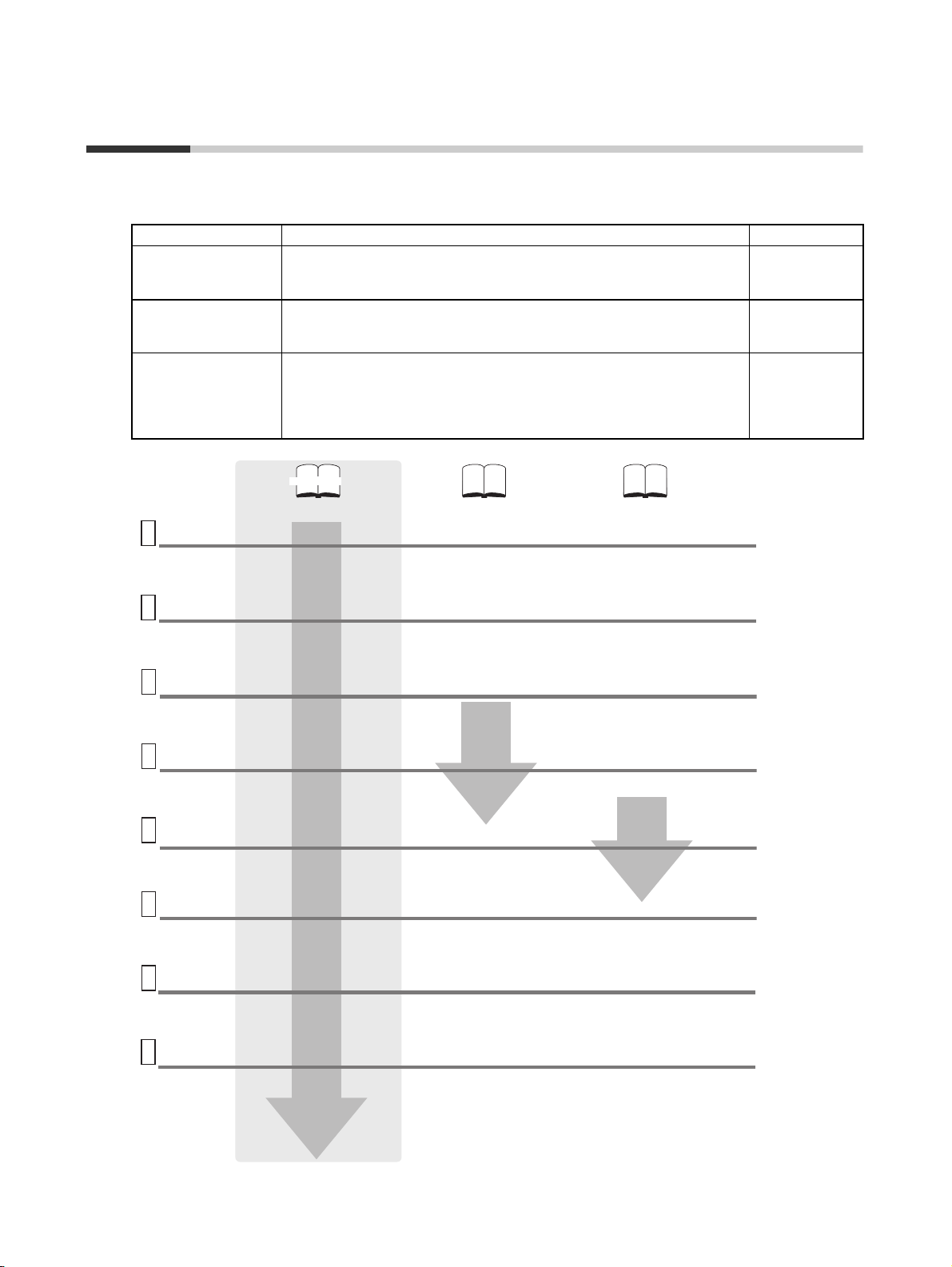
Manual Configuration
Information on the operation of G9SP-series Safety Controllers is provided in the following manuals.
Refer to the specific manual depending on the information that is required.
Manual name Contents Cat. No.
G9SP-series Safety
Controller Operation
Manual (this manual)
G9SP-series Safety
Controller Instructio ns
Reference Manual
G9SP-series Safety
Controller Host Connection Manual
System
configuration
1
settings
• Unit type, nomenclature, and specifications
• Configuring hardware
• Calculating safety response performance
Installation
2
and Wiring
• Precautions for installation in a panel
• Performing power supply wiring
Support
Software
3
Startup
Software
settings and
4
programming
Control
PLC
5
Design
Checking
and
debugging
6
operation
Operation
and
7
Maintenance
• Performing I/O wiring
• Installing the Support Software (G9SP
• Starting the Support Software
• Creating configuration data in the
• Setting the control PLC to
• Downloading configuration data to the
• Checking operation using the Support
• Replacement at G9SP failure
• Updating the configuration data in the
This manual provides detailed specifications and describes functions
and application methods for the G9SP-series Controller in detail.
This manual describes the safety programming methods, provides the
specifications, and describes the functions and operating methods of the
G9SP-series Controllers.
This manual provides sample ladder programming and describes how to
connect to a Standard PLC from another manufacturer using the communications functionality of the G9SP-series Controller's Option Board.
The procedure for connecting to a Standard PLC from another manufacturer is described in the G9SP Operation Manual.
This manual
G9SP-series Safety Controller
Operation Manual
(Cat. No. Z922)
Configurator)
Support Software
communicate with the G9SP
G9SP
Software
G9SP
G9SP-series Safety Controller Instructions
Reference Manual
(Cat. No. Z923)
• Safety logic programming
• Function block operation specifications
G9SP-series Safety Controller
Host Connection Manual
(Cat. No. Z924)
Note: Provided only as a PDF file.
• Sample ladder programming for the
control PLC
Z922
Z923
Z924
8
Troubleshooting
• Corrective measures and error codes
for troubleshooting
x
Page 11

Sections in this Manual
Overview
1
Part Names and
2
Specifications
Calculating Response
3
Performance
Installation and Wiring
4
Preparations for Using
5
the G9SP Configurator
Creating Configuration Data
6
Checking Operating
10
Status and Debugging
Backup and Restore Data
11
Using Memory Cassette
Maintenance and
12
Inspections
Troubleshooting
13
Application Templates
A
Communications with a Standard PLC Using
7
an Option Board
Connecting Online and Downloading to the
8
G9SP-series Controller
Operation and Operating Modes
9
xi
Page 12

xii
Page 13

Terms and Conditions Agreement
Warranty, Limitations of Liability
Warranties
● Exclusive Warranty Omron’s exclusive warranty is that the Products will be free from defects in
materials and workmanship for a period of twelve months from the date of
sale by Omron (or such other period expressed in writing by Omron). Omron
disclaims all other warranties, express or implied.
● Limitations OMRON MAKES NO WARRANTY OR REPRESENTATION, EXPRESS OR
IMPLIED, ABOUT NON-INFRINGEMENT, MERCHANTABILITY OR FITNESS FOR A PARTICULAR PURPOSE OF THE PRODUCTS. BUYER
ACKNOWLEDGES THAT IT ALONE HAS DETERMINED THAT THE PRODUCTS WILL SUITABLY MEET THE REQUIREMENTS OF THEIR INTENDED
USE.
Omron further disclaims all warranties and responsibility of any type for claims
or expenses based on infringement by the Products or otherwise of any intellectual property right.
● Buyer Remedy Omron’s sole obligation hereunder shall be, at Omron’s election, to (i) replace
(in the form originally shipped with Buyer responsible for labor charges for
removal or replacement thereof) the non-complying Product, (ii) repair the
non-complying Product, or (iii) repay or credit Buyer an amount equal to the
purchase price of the non-complying Product; provided that in no event shall
Omron be responsible for warranty, repair, indemnity or any other claims or
expenses regarding the Products unless Omron’s analysis confirms that the
Products were properly handled, stored, installed and maintained and not
subject to contamination, abuse, misuse or inappropriate modification. Return
of any Products by Buyer must be approved in writing by Omron before shipment. Omron Companies shall not be liable for the suitability or unsuitability or
the results from the use of Products in combination with any electrical or electronic components, circuits, system assemblies or any other materials or substances or environments. Any advice, recommendations or information given
orally or in writing, are not to be construed as an amendment or addition to
the above warranty.
Limitation on
Liability; Etc
See http://www.omron.com/global/ or contact your Omron representative for
published information.
OMRON COMPANIES SHALL NOT BE LIABLE FOR SPECIAL, INDIRECT,
INCIDENTAL, OR CONSEQUENTIAL DAMAGES, LOSS OF PROFITS OR
PRODUCTION OR COMMERCIAL LOSS IN ANY WAY CONNECTED WITH
THE PRODUCTS, WHETHER SUCH CLAIM IS BASED IN CONTRACT,
WARRANTY, NEGLIGENCE OR STRICT LIABILITY.
Further, in no event shall liability of Omron Companies exceed the individual
price of the Product on which liability is asserted.
xiii
Page 14

Application Considerations
Suitability of Use Omron Companies shall not be responsible for conformity with any standards,
codes or regulations which apply to the combination of the Product in the
Buyer’s application or use of the Product. At Buyer’s request, Omron will provide applicable third party certification documents identifying ratings and limitations of use which apply to the Product. This information by itself is not
sufficient for a complete determination of the suitability of the Product in combination with the end product, machine, system, or other application or use.
Buyer shall be solely responsible for determining appropriateness of
the particular Product with respect to Buyer’s application, product or system.
Buyer shall take application responsibility in all cases.
NEVER USE THE PRODUCT FOR AN APPLICATION INVOLVING SERIOUS
RISK TO LIFE OR PROPERTY WITHOUT ENSURING THAT THE SYSTEM
AS A WHOLE HAS BEEN DESIGNED TO ADDRESS THE RISKS, AND
THAT THE OMRON PRODUCT(S) IS PROPERLY RATED AND INSTALLED
FOR THE INTENDED USE WITHIN THE OVERALL EQUIPMENT OR SYSTEM.
Programmable
Products
Omron Companies shall not be responsible for the user’s programming of a
programmable Product, or any consequence thereof.
Disclaimers
Performance Data Data presented in Omron Company websites, catalogs and other materials is
provided as a guide for the user in determining suitability and does not constitute a warranty. It may represent the result of Omron’s test conditions, and the
user must correlate it to actual application requirements. Actual performance
is subject to the Omron’s Warranty and Limitations of Liability.
Change in
Specifications
Errors and Omissions Information presented by Omron Companies has been checked and is
Product specifications and accessories may be changed at any time based on
improvements and other reasons. It is our practice to change part numbers
when published ratings or features are changed, or when significant construction changes are made. However, some specifications of the Product may be
changed without any notice. When in doubt, special part numbers may be
assigned to fix or establish key specifications for your application. Please consult with your Omron’s representative at any time to confirm actual specifications of purchased Product.
believed to be accurate; however, no responsibility is assumed for clerical,
typographical or proofreading errors or omissions.
xiv
Page 15
Safety Precautions
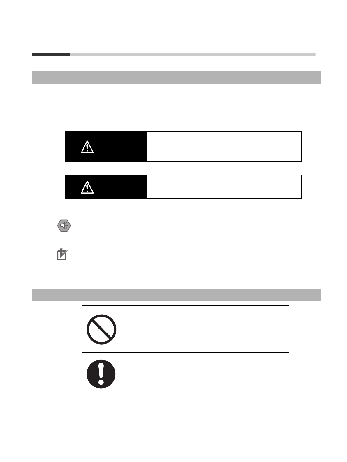
Definition of Precautionary Information
The following notation is used in this manual to provide precautions required to ensure safe usage of a
G9SP-series Controller. The safety precautions that are provided are extremely important to safety.
Always read and heed the information provided in all safety precautions.
The keywords and their definitions are as given below.
Indicates a potentially hazardous situation which, if not avoided,
WARNING
will result in minor or moderate injury, or may result in serious
injury or death. Additionally there may be significant property
damage.
Indicates precautions on what to do and what not to do to ensure using the product safely.
Indicates precautions on what to do and what not to do to ensure proper operation and performance.
Symbols
Caution
Precautions for Safe Use
Precautions for Correct Use
The circle and slash symbol indicates operations that you must not do.
The specific operation is shown in the circle and explained in text.
Indicates a potentially hazardous situation which, if not avoided,
may result in minor or moderate injury or in property damage.
The filled circle symbol indicates operations that you must do. The
specific operation is shown in the circle and explained in text. This
example shows a general precaution for something that you must do.
xv
Page 16

WARNING
This is the Operation Manual for the G9SP-series Safety Controllers.
Obey the following warnings during system construction to ensure that safety-related components are configured to
enable the system functions to sufficiently operate.
● Risk Assessment
The proper use of the safety devices described in this manual as they relate to installation conditions and mechanical
performance and functions is a prerequisite for its use.
When selecting or using the safety devices, risk assessment must be performed during the development stage of the
equipment or facilities to identify potential danger factors in equipment or facilities in which the safety devices are to be
applied. Suitable safety devices must be selected under the guidance of a sufficient risk assessment system. An insufficient risk assessment system may result in the selection of unsuitable safety devices.
• Typical related international standards: ISO 14121, Safety of Machinery -- Principles of Risk Assessment
● Safety Measures
When using this safety device to build systems containing safety-related components for equipment or facilities, the
system must be designed with the full understanding of and conformance to international standards, such as those
listed below, and/or standards in related industries.
• Typical related international standards: ISO/DIS 12100, Safety of Machinery -- Basic Concepts and General
Principles for Design
IEC 61508, Safety Standard for Safety Instrumented Systems (Functional Safety of Electrical/Electronic/Programmable Electronic Safety-related Systems)
● Role of Safety Devices
The safety devices are provided with safety functions and mechanisms as stipulated in relevant standards, but suitable
designs must be used to enable these functions and mechanisms to operate properly inside system constructions containing safety-related components. Build systems that enable these functions and mechanisms to perform properly,
based on a full understanding of their operation.
• Typical related international standards: ISO 14119, Safety of machinery -- Interlocking devices associated with
guards -- Principles for design and selection
● Installation of Safety Devices
The construction and installation of systems with safety-related components for equipment or facilities must be performed by technicians who have received suitable training.
• Typical related international standards: ISO/DIS 12100, Safety of Machinery -- Basic Concepts and General
Principles for Design
IEC 61508, Safety Standard for Safety Instrumented Systems (Functional Safety of Electrical/Electronic/Programmable Electronic Safety-related Systems)
● Compliance with Laws and Regulations
This safety device conforms to the relevant regulations and standards, but make sure that it is used in compliance with
local regulations and standards for the equipment or facilities in which it is applied.
• Typical related international standards: IEC 60204, Safety of Machinery -- Electrical Equipment of Machines
● Observing Precautions for Use
When putting the selected safety device to actual use, heed the specifications and precautions in this manual and
those in the instruction manual that comes with the product. Using a product in a manner that deviates from these
specifications and precautions will lead to unexpected failures in equipment or devices, and to damage that results
from such failures, due to insufficient operating functions in safety-related components.
● Moving or Transferring Devices or Equipment
When moving or transferring devices or equipment, be sure to include this manual to ensure that the person to whom
the device or equipment is being moved or transferred will be able to operate it properly.
• Typical related international standards: ISO/DIS 12100, Safety of Machinery -- Basic Concepts and General
Principles for Design
IEC 61508, Safety Standard for Safety Instrumented Systems (Functional Safety of Electrical/Electronic/Programmable Electronic Safety-related Systems)
xvi
Page 17
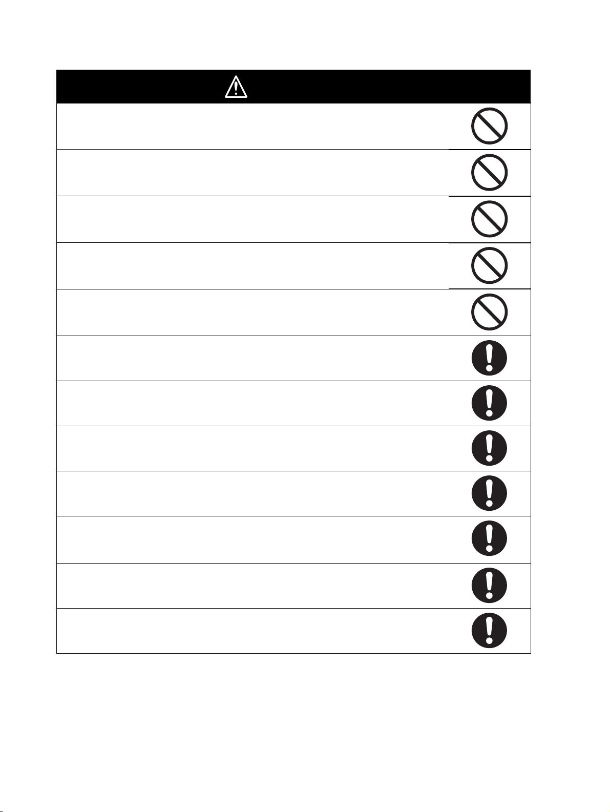
WARNING
Electric shock may occur. Do not touch any terminals while power is being supplied.
Serious injury may possibly occur due to loss of required safety functions. Do not use the
G9SP-series Controller's test outputs or standard outputs as safety outputs.
Serious injury may possibly occur due to loss of required safety functions. Do not use the
G9SP-series Controller's network data as safety data.
Serious injury may possibly occur due to loss of required safety functions. Do not use indicators on the G9SP-series Controller for safety operations.
Serious injury may possibly occur due to breakdown of safety outputs or test outputs. Do not
connect loads beyond the rated values to the safety outputs and test outputs.
Serious injury may possibly occur due to loss of required safety functions. Wire the G9SPseries Controller properly so that the 24VDC line does NOT touch the outputs accidentally or
unintentionally.
Serious injury may possibly occur due to loss of required safety functions. Ground the 0V line
of the power supply for external output devices so that the devices do NOT turn ON when the
safety output line or the test output line is grounded.
Serious injury may possibly occur due to loss of required safety functions. Perform user testing
and confirm that all of the G9SP-series Controller’s configuration data and operation is correct
before starting system operation.
Serious injury may possibly occur due to loss of required safety functions. When replacing a
G9SP-series Controller, confirm the model of the Controller is correct and configure the
replacement Controller suitably and confirm that it operates correctly.
Serious injury may possibly occur due to loss of required safety functions. Once the data has
been restored from the Memory Cassette, check that the configuration data of the G9SP-series
Controller is correct in that it operates properly and carry out the validation testing (User Testing).
Outputs may operate, possibly resulting in serious injury. Take sufficient safety measures
before force-setting or force-resetting variables in the program.
Serious injury may possibly occur due to loss of required safety functions. Use devices and
parts related to safety functions according to legal regulations in the applicable country. Use
certified items compliant with safety standards corresponding to the intended application.
xvii
Page 18
Precautions for Safe Use
● Handling
Do not drop the G9SP-series Controller or subject it to excessive vibration or mechanical shock. The
G9SP-series Controller may be damaged and may not function properly.
● Installation and Storage Environment
Do not use or store the G9SP-series Controller in any of the following locations:
• Locations subject to direct sunlight
• Locations subject to temperatures or humidity outside the range specified in the
specifications
• Locations subject to condensation as the result of severe changes in temperature
• Locations subject to corrosive or flammable gases
• Locations subject to dust (especially iron dust) or salts
• Locations subject to water, oil, or chemicals
• Locations subject to shock or vibration
Take appropriate and sufficient measures when installing systems in the following locations. Inappropriate and insufficient measures may result in malfunction.
• Locations subject to static electricity or other forms of noise
• Locations subject to strong electromagnetic fields
• Locations subject to possible exposure to radioactivity
• Locations close to power supplies
This is a class A product designed for use in industrial environments. In residential areas it may cause
radio interference, in which case the user may be required to take adequate measures to reduce interference.
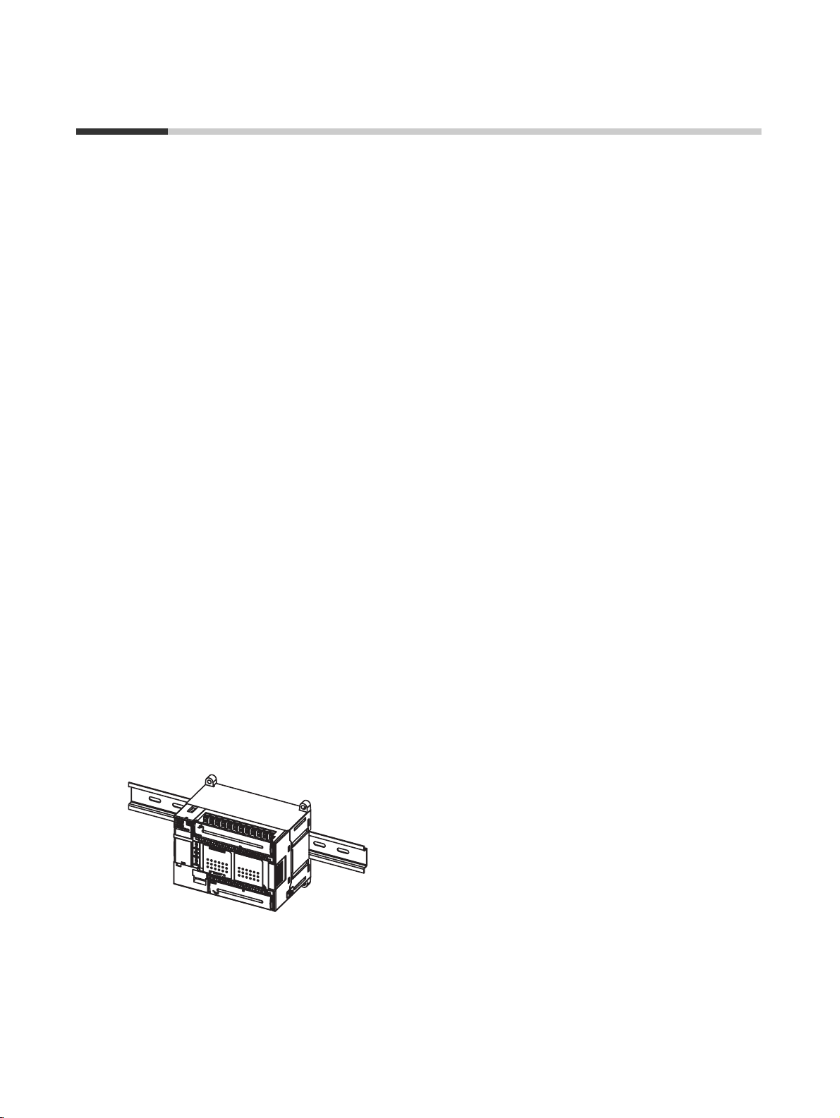
● Installation and Mounting
• Use the G9SP-series Controller within an enclosure with IP54 protection or higher according to IEC/
EN 60529.
• Use DIN Track (TH35-7.5/TH35-15 according to IEC 60715) or M4 screws with a tightening torque of
1.2 N·m (10.5 lb·in) to install the G9SP-series Controller into the control panel.
• Mount the G9SP-series Controller to the DIN Track using PFP-M End Plates (not included with the
G9SP-series Controller) to prevent it from falling off the DIN Track because of vibration. Correctly
mount all Units to DIN Track.
• Install the G9SP-series Controller in the vertical direction shown below to ensure adequate cooling.
• Space must be provided around the G9SP-series Controller, at least 20 mm from its side surfaces and
at least 50 mm from its top and bottom surfaces, for ventilation, wiring and Unit replacement.
• Be sure to lock all locking mechanisms, such as those on I/O terminal blocks and connectors, before
attempting to use the G9SP-series Controller.
xviii
Page 19
Turn OFF the power supply before performing any of the following.
• Connecting or disconnecting Expansion I/O Units, Option Boards, or any other Units
• Assembling the G9SP-series Controller
• Connecting cables or wiring
• Connecting or removing terminal blocks
● Installation and Wiring
• Use the following to wire external I/O devices to the G9SP-series Controller.
Solid wire
Stranded wire
0.32 to 0.82 mm
0.32 to 0.5 mm
0.5 to 1.3 mm
0.5 to 0.82 mm
*1: When wiring two wires to one terminal. Use two wires of the same type and thickness.
• M3 self-rising screws are used for all screw terminals.
• Tighten the terminal block screws to a torque of 0.5 N·m (4.4 lb·in).
• Disconnect the G9SP-series Controller from the power supply before starting wiring. Devices connected to the G9SP-series Controller may operate unexpectedly.
• Properly apply the specified voltage to the G9SP-series Controller inputs. Applying an inappropriate
DC voltage or any AC voltage will cause the G9SP-series Controller to fail.
• Be sure to separate the communications cables and I/O cables from high-voltage/high-current lines.
• Be cautious not to get your fingers caught when attaching connectors to the plugs on the G9SP-series
Controller.
• Incorrect wiring may lead to loss of safety functions. Wire conductors correctly and verify the operation
of the G9SP-series Controller before using the system in which the G9SP-series Controller is incorporated.
• Lock the connectors on Option Units or Expansion I/O Units before using the Units.
• After wiring is completed, be sure to remove the label for wire clip entry prevention from the G9SPseries Controller to enable heat to escape for proper cooling.
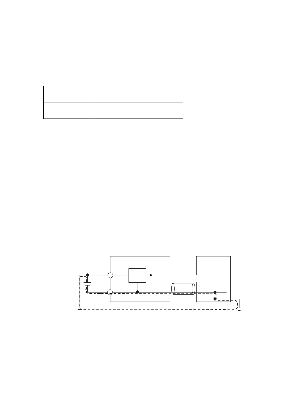
• Do not ground the 24-V side of the power supply to the G9SP-series Controller. If you do so, an
unwanted current flow shown in the following diagram may occur when you connect a computer or
other peripheral device.
2
AWG22 to AWG18
2
AWG22 to AWG20*1
2
AWG20 to AWG16
2
AWG20 to AWG18*1
G9SP
Peripheral device
Power supply circuit
24 V
USB cable
GND
0 V
0 V
• Connect no more than the specified number of Expansion I/O Units.
0 V
FG
xix
Page 20

● Power Supply Selection
Use a DC power supply satisfying the following requirements.
• The secondary circuit of the DC power supply must be isolated from the primary circuit by double insulation or reinforced insulation.
• The output characteristic requirements defined in UL 508 for class 2 circuits or control voltage current circuits are satisfied.
• The output hold time must be 20 ms or longer.
• The DC power supply must be an SELV power supply that satisfies the requirements
of IEC/EN 60950-1 and EN 50178.
● Periodic Inspections and Maintenance
• Disconnect the G9SP-series Controller from the power supply before replacing the Controller. Devices
connected to the G9SP-series Controller may operate unexpectedly.
• Do not disassemble, repair, or modify the G9SP-series Controller. Doing so may lead to loss of safety
functions.
● Disposal
Be cautious not to injure yourself when dismantling the G9SP-series Controller.
xx
Page 21
Precautions for Compliance with UL
Standards and CSA Standards
Use the following installation information instead of the general information in the instruction manual in
order to use the product under certified conditions of UL and CSA when the product is installed in the
USA or Canada. These conditions are required by NFPA 70 (National Electrical Code in the USA) and
Part 1 of the Canadian Electrical Code in Canada and may vary from information given in the product
manuals or safety precautions. G9SP-series Controllers have not been evaluated by UL as Programmable Safety Controllers, and the Safety functions of these devices have not been evaluated by UL as well.
• Surrounding air temperature: 55°C
• Do not use crimp terminals for field wiring.
• The DC power supply must satisfy the requirements for an isolated power supply
with external 8 A overcurrent protection.
• Do not use the +5 V output from the CP1W-CIF01 for anything other than the NTAL001.
• A G9SP-series Controller has two sets of power supply terminals, one for the main
power and one for I/O power. Connect both of them to the same power source.
● Ratings
Controller Rating for UL
G9SP-N20S Source: 24 V dc, 500 mA, isolated source
Input: 24 V dc, 6 mA /P, 20 points
Output: 24 V dc (GEN) (P.D.), 0.8 A /P, 8 points
Rated total currents of So0 to 3, So4 to 7 are 1.6 A each
Test Output:
T0 − T2: 24 V dc (GEN), 100 mA
T3: 24 V dc (GEN)(TUN), 300 mA
T4, T5: 24 V dc (GEN), 30 mA
Rated total currents of T0 − T2, T4 and T5 are 120 mA
G9SP-N10D Source: 24 V dc, 500 mA, isolated source
Input: 24 V dc, 6 mA, 10 points
Output: 24 V dc (GEN) (P.D.), 0.8 A /P, 16 points
Rated total currents of So0 to 3, So4 to 7, So8 to 11, So12 to So15 are 1.2 A each
Test Output:
T0 − T2: 24 V dc (GEN), 60 mA
T3: 24 V dc (GEN)(TUN), 300 mA
T4, T5: 24 V dc (GEN), 30 mA
Rated total currents of T0 − T2, T4 and T5 are 60 mA
G9SP-N10S Source: 24 V dc, 400 mA, isolated source
Input: 24 V dc, 6 mA /P, 10 points
Output: 24 V dc (GEN) (P.D.), 0.8 A /P, 1.6 A /Unit, 4 points
Test Output:
T0, T1: 24 V dc (GEN), 60 mA
T2: 24 V dc (GEN), 30 mA
T3: 24 V dc (GEN)(TUN), 300 mA
Rated total currents of T0 − T2 are 60 mA
Standard Output: 24 V dc (GEN), 100 mA, 4 points
● TERMINAL MARKINGS
Terminals Function
V1/G1 Power supply terminals for Internal/Input circuits (24 VDC).
V2/G2 Power supply terminals for output circuits (24 VDC).
NC Not used (Do not connect)
Si0 to Si19 Input terminals
T0 to T5 Test output terminals
So0 to So15 Output terminals
O0 to O3 Standard output terminals
xxi
Page 22
Regulations and Standards
The G9SP-series Controller has obtained certification for the following standards.
Certifying body Standards
TÜV Rheinland • EN ISO 13849-1:2015
• EN ISO 13849-2:2012
• IEC 61508 parts 1-7:2010
• EN 62061:2005+A1:2013+A2:2015
• IEC 61131-2:2007
• EN ISO 13850:2015
UL • UL508 • CSA22.2 No.142
KOSHA
Others • CE Marking
*1 The G9SP-series Controller (version 1.1 or later) and the Expansion I/O Units have been certified for
the KOSHA S Mark.
Using a G9SP-series Controller enables building a safety control system that satisfy the following:
•S Mark
• C-Tick mark
• Requirements for SIL 3 (Safety Integrity Level 3) in IEC 61508, IEC/EN 62061,
Safety Standard for Safety Instrumented Systems (Functional Safety of Electrical/
Electronic/Programmable Electronic Safety-related Systems)
• Requirements for PLe (Performance Level e) and for safety category 4 in EN
ISO13849-1
*1
• EN 60204-1:2006+A1:2009
• EN 61000-6-2:2005
• EN 61000-6-4:2007+A1:2011
• NFPA 79-2015
• ANSI RIA 15.06-2012
• ANSI B11.19-2010
• ANSI/UL 1998:2013
Compliance with EC Directives
Applicable Directives
• EMC Directive (2014/30/EU)
• Machinery Directive (2006/42/EC)
Concepts
● EMC Directive
OMRON electrical devices are built into other components or equipment. OMRON therefore pursues
compliance with the related EMC standards so that they can be more easily built into other devices or
the equipment.*
OMRON cannot confirm compliance in the customer's actual application, however, because the customer may use a variety of components and equipment, and EMC performance depends on the configuration, wiring, and arrangement of the equipment and control panel into which a product applicable to
EC Directives is incorporated. Therefore, whether the products conform to the standards in the system
used by the customer must be checked by the customer.
* Applicable EMC (Electromagnetic Compatibility) standards are as follows: EN
61000-6-2 for EMS (Electromagnetic Susceptibility) and EN 61000-6-4 for Electromagnetic Interference (10-m regulations applied for EN 61000-6-4 radiated emission).
xxii
Page 23

● Machinery Directive
The Machinery Directive requires ensuring the required safety for safety components used for machinery safety.
Applicable standards: EN ISO 13849-1:2015 and IEC/EN 62061 SIL CL3
● Conformance to EC Directives
The G9SP-series Controller complies with EC Directives. To ensure that the machine or device in which
the G9SP-series Controller is used complies with EC Directives, the following requirements must be
met.
• Make sure that the DC power supply connected to a DC Power Supply Unit or I/O
Unit satisfies the following conditions.
• There is double insulation or reinforced insulation between the primary circuit and secondary circuit.
• An isolated power supply that is limited to a current of 8 A or lower must be
used.
• The output hold time is 20 ms min.
• The power supply is a SELV power supply that satisfies requirements in IEC/
EN 60950-1 and EN 50178.
• G9SP-series products that comply with the EC Directives also comply with the
Generic Emission Standard (EN 61000-6-4) for EMI. The radiated emission characteristics (10-m regulations), however, may depend on the configuration of the control
panel that is used and the relation to and wiring with other connected devices. Even
through the G9SP-series Controller complies with EC Directives, the customer must
confirm that the overall machinery and equipment in which the G9SP-series Controller is used complies with the EC Directives.
EN ISO 13849-1 and IEC/EN 62061 Compliance
EN ISO 13849-1 and IEC/EN 62061 require process management to avoid system interference and to
simplify reading, understanding, testing, and maintaining software. This is required in all phases of the
life cycle of software programming and software design (e.g., basic software design, safety circuit system design, and software upgrades) in safety control systems to be developed using safety controllers.
Therefore, process management is required for design and development of software for facilities and
equipment that use the function blocks provided in the Safety Controller.
The customer must implement measures to ensure compliance with these standards.
To obtain the reliability data for safety of machinery to verify the safety performance of your equipment,
go to the following URL: http://www.ia.omron.com/support/sistemalibrary/index.html.
xxiii
Page 24

Glossary
The following terms are used in this manual to describe the function blocks of the G9SP-series Safety
Controllers.
Terminology
Term Definition
Safety Describes a device, function, data, or other element for which special safety measures
have been implemented for use in Safety Controls.
Standard Describes a device, function, data, or other element that is used in Standard Controls.
Used to differentiate from devices, functions, data, or other elements for which special
safety measures have been implemented for use in Safety Controls.
Safety Controller A highly reliable controller that is used in Safety Controls.
Standard PLC A programmable controller (PLC) that is used for general controls.
Used to differentiate from a PLC used for Safety Controls.
Expansion I/O Unit The name of the CP1W-20EDT(-1) and CP1W-32ET(-1).
Some of the OMRON CP1-series Expansion I/O Units can be used in a G9SP-series
Controller. Expansion I/O Units are connected to a G9SP-series Controller to increase
the number of Standard I/O points.
Option Board The name of the CP1W-CIF01 and CP1W-CIF41.
Some of the OMRON CP1-series Option Boards can be used in a G9SP-series Control-
ler. An Option Board can be mounted in a G9SP-series Controller to communicate with a
Standard PLC.
Memory Cassette The name of the CP1W-ME05M.
This OMRON CP1@-series Memory Cassette can be used in a G9SP-series Controller. It
is used to back up and restore configuration data in G9SP-series Controllers.
G9SP Configurator The name of the WS02-G9SP@@.
Support Software that is used to set up, program, and debug G9SP-series Controllers.
configuration data Setup data that is used to operate a G9SP-series Controller. The configuration data is
created with the G9SP Configurator and then downloaded from the computer to memory
in the G9SP-series Controller. The configuration data contains the unit configuration set-
tings, I/O terminal settings, system settings, and Safety Program. Refer to SECTION 6
Creating Configuration Data for details.
backup An operation used to write the configuration data stored in internal memory in the G9SP-
series Controller to a Memory Cassette.
restore An operation used to write the configuration data stored in a Memory Cassette to internal
memory in the G9SP-series Controller.
Safety Input Device An input device for which special safety measures have been implemented for use in
Safety Controls. Safety Input Device is therefore a generic term for input devices such as
emergency stop switches and safety door switches.
Safety Output Device An output device for which special safety measures have been implemented for use in
Safety Controls. Safety Output Device is therefore a generic term for output devices such
as safety relays.
CP Series A series of programmable controllers manufactured by OMRON.
NE1A Series A series of Safety Network Controllers manufactured by OMRON. NE1A-series Control-
lers are high-end controllers in comparison to the G9SP-series Controllers.
dual channels Two channels that are used for redundancy with Safety Inputs or Safety Outputs. If the
two channels must have the same value, they are called equivalent dual channels. If they
must have the opposite values, they are called complementary dual channels.
discrepancy The state in which the status of two dual channels do not agree, resulting in a discrep-
ancy error.
xxiv
Page 25

Acronyms
Acronym Meaning
MC Memory Cassette.
Si Safety Input.
An input from a Safety Input terminal. This term is used to differentiate from a
Standard Input (IN).
So Safety Output.
An output from a Safety Output terminal. This term is used to differentiate from
a Standard Output (OUT).
To Test Ou t p u t .
An output from a Test Output terminal used to diagnose a Safety Input terminal
by outputting a test pulse.
xxv
Page 26

xxvi
Page 27

Overview
SECTION 1
Overview
This section provides an overview and describes the features, system configuration, and application procedures for the
G9SP-series Controller.
1-1 Overview and Features of the G9SP-series Controller . . . . . . . . . . . . . . . . . . 2
1-1-1 Overview. . . . . . . . . . . . . . . . . . . . . . . . . . . . . . . . . . . . . . . . . . . . . . 2
1-1-2 Basic System and Configuration Devices. . . . . . . . . . . . . . . . . . . . . 2
1-1-3 Features. . . . . . . . . . . . . . . . . . . . . . . . . . . . . . . . . . . . . . . . . . . . . . . 5
1-2 Basic Operating Procedures . . . . . . . . . . . . . . . . . . . . . . . . . . . . . . . . . . . . . . 9
1
Page 28
Overview and Features of the G9SP-series Controller Section 1-1
1-1 Overview and Features of the G9SP-series Controller
1-1-1 Overview
The G9SP-series Safety Controller is a programmable controller that is
designed for easy operation in small to mid-sized Safety Control systems.
Using the G9SP-series Safety Controller enables building Safety Control systems that satisfy the requirements for SIL 3 (Safety Integrity Level 3) in IEC
61508 (Safety Standard for Safety Instrumented Systems: Functional Safety
of Electrical/Electronic/Programmable Electronic Safety-related Systems) and
IEC/EN 62061 (Safety of Machinery -- Functional Safety of Safety-related
Electrical, Electronic and Programmable Electronic Control Systems), as well
as safety category 4 and PLe (Performance Level e) in EN ISO 13849-1.
The use of Expansion I/O Units and optional products enables a wide variety
of applications.
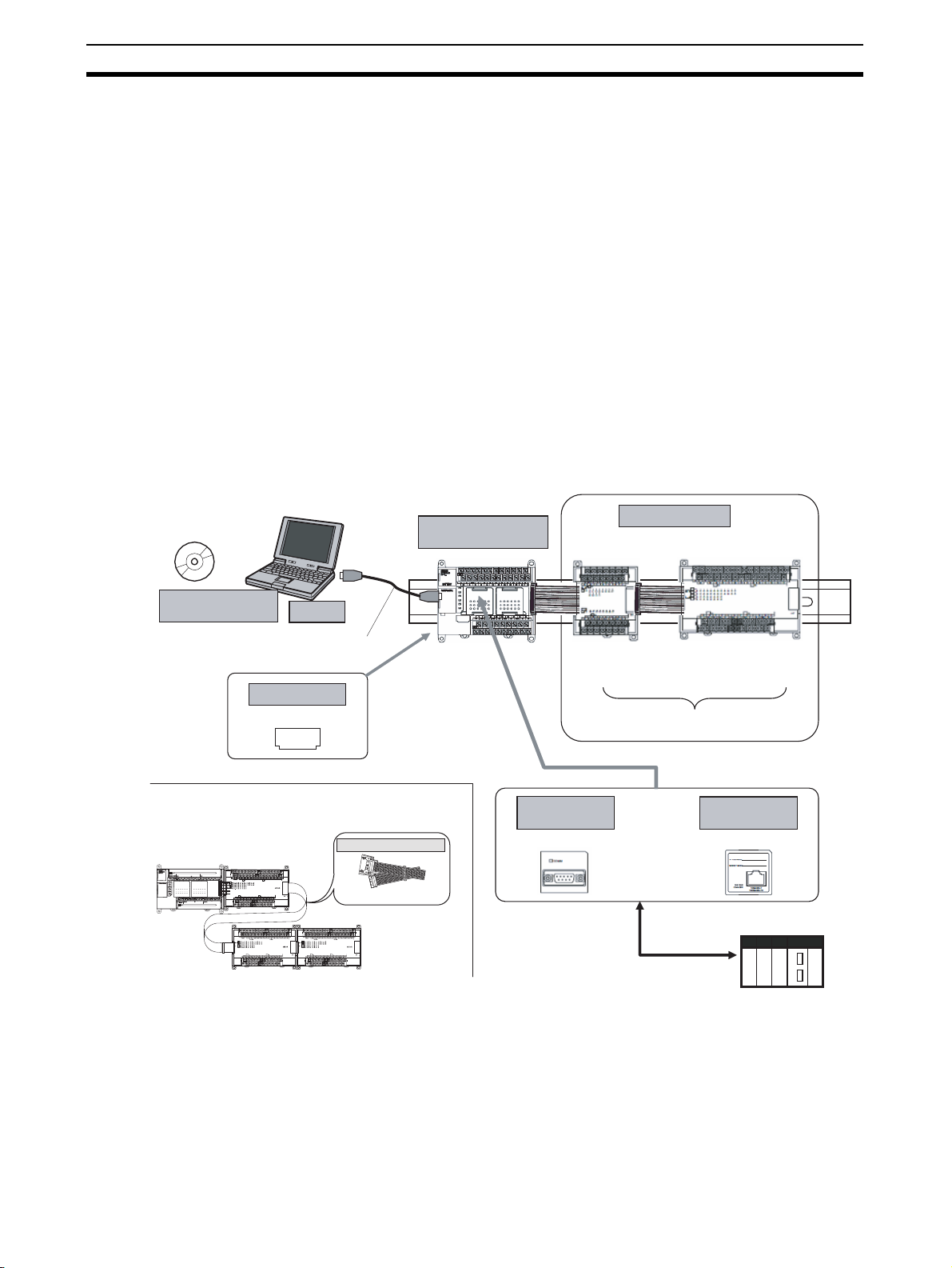
1-1-2 Basic System and Configuration Devices
This section describes the basic system configuration for a G9SP-series Controller.
G9SP Configurator
Support Software
WS02-G9SP@@@
When distance is required between the Units, for example,
when a two-level layout is created using Expansion I/O Units.
G9SP-series
Controller
Computer
USB cable
G9SP-N@@@
Memory Cassette
CP1W-ME05M
MEMORY
I/O Connecting Cable
CP1W-CN811
Expansion I/O Units
G9SP-series
Safety Controller
RS-232C or
Ethernet communications
Expansion I/O Units
CP1W-20EDT/EDT1
CP1W-32ET/ET1
The G9SP-series Safety Controller can be
expanded using up to two Expansion I/O Units.
RS-232C
Option Board
CP1W-CIF01
CP1W-CIF41 (unit version 2.0 or later)
Or
Ethernet
Option Board
Standard PLC
2
Page 29
Overview and Features of the G9SP-series Controller Section 1-1
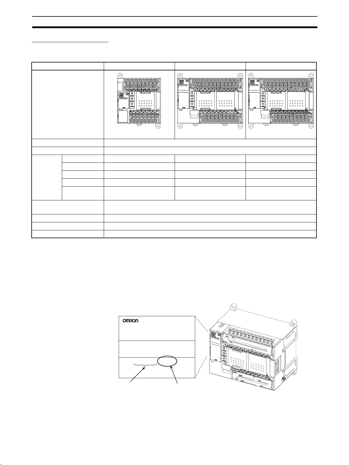
G9SP-series Controller
There are three models of G9SP-series Controllers depending on the number
of Safety I/O points.
Name/model G9SP-N10S G9SP-N10D G9SP-N20S
Appearance
W66 x H110 x D65 (mm) W130 x H110 x D85 (mm) W130 x H110 x D85 (mm)
Power supply 24 VDC
Program size Function blocks: 128 max.
Number of
I/O points
Expansion using Expansion
I/O Units
Mounting Option Boards One Option Board can be mounted.
Using Memory Cassettes Supported
Mounting a battery Not supported
Safety Inputs 10 points 10 points 20 points
Safety Outputs 4 semiconductor outputs 16 semiconductor outputs 8 semiconductor outputs
Test Outputs 4 points 6 points 6 points
Standard Inputs None None None
Standard Out-
4 semiconductor outputs None None
puts
Up to 2 Expansion I/O Units can be mounted.
Unit Versions of G9SP-series Controller
A “unit version” has been introduced to manage G9SP-series Controllers
according to differences in functionality accompanying Controller upgrades.
• Notation of Unit Versions on Products
Product nameplate
G9SP
SAFETY
CONTROLLER
Lot No. 28705 0000 Ver.1.0
OMRON Corporation MADE IN CHINA
Lot No.
• Confirming Unit Versions with the G9SP Configurator (version 1.10 or
higher)
The unit version is given to the right of the lot number on the nameplate
of the products for which unit versions are being managed, as shown
below.
G9SP-series
Safety Controller
Unit version
(example for unit version 1.0)
3
Page 30
Overview and Features of the G9SP-series Controller Section 1-1
You can check the unit version by right-clicking the unit name in the
Project Window and selecting Properties from the G9SP Configura-
tor.
■ Unit Versions
The information provided in this manual applies to all unit versions unless otherwise specified.
Model Model numbers Unit version
G9SP-series Controller G9SP-N@@@ Unit version 1.0
Unit version 1.1
Unit version 2.0
Unit version 1.1 or later is certified for the KOSHA S Mark.
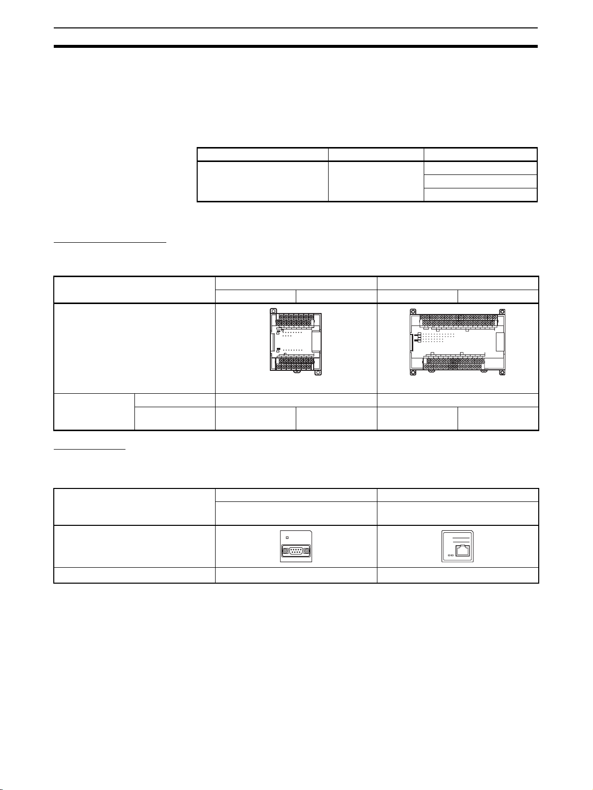
Expansion I/O Units
The following four models of CP-series Expansion I/O Units can be used.
The CP1W-CN811 I/O Connecting Cable can also be used.
Name/model Unit with 20 Standard I/O points Unit with 32 Standard I/O points
CP1W-20EDT CP1W-20EDT1 CP1W-32ET CP1W-32ET1
Appearance
COM 01 03 05 07 09 11
NC 00 02 04 06 08 10
CH
IN
CH
00 01 02 03
04 05 06 07
08 09 10 11
OUT
CH
00 01 02 03 04 05 06 07
CH
NC 00 01 02 04 05 07
NC COM COM COM 03 COM 06
EXP
NCNCNC
COM
01 03 05 07 09 11 01 03 05 07 09 11
NC
00 02 04 06 08 10
CH CH
CH
IN
CH
CH
0706050403020100
OUT
CH
0706050403020100
CH CH
NC
00 01 02 04 05 07 00 02 04 05 07
NC
COM COM COM COM COM COM03 06 01 03 06
111009080706050403020100
111009080706050403020100
00 02 04 06 08 10
EXP
W86 x H110 x D50 (mm) W150 x H110 x D50 (mm)
Number of I/O
points
Standard Inputs 12 points None
Standard Outputs 8 semiconductor
outputs (sinking)
Option Units
Option Boards
The following two models of CP-series Option Boards can be used.
Name/model RS-232C Option Board Ethernet Option Board
Appearance
Protocol No-protocol
*1 Communications with an OMRON Standard PLC can be performed using
FINS/UDP.
Memory Cassette
The CP1W-ME05M CP-series Memory Cassette can be used.
8 semiconductor
outputs (sourcing)
32 semiconductor
outputs (sinking)
32 semiconductor
outputs (sourcing)
CP1W-CIF01 CP1W-CIF41
(unit version 2.0 or later)
COMM
*1
UDP/IP
IP ADDRESS:
SUBNET MASK:
COMMERR
10BASE-T
100BASE-TX
4
Page 31

Overview and Features of the G9SP-series Controller Section 1-1
I/O Connecting Cable
Only one CP-series I/O Connecting Cable can be used. Use this cable when
the length of the cable for the Expansion I/O Units is insufficient or when the
Units are arranged vertically.
Name/model I/O Connecting Cable
CP1W-CN811
Appearance
Length 800 (mm)
Precautions for Correct Use
Operation may be unpredictable if any Units other than the Expansion I/O
Units and Option Units listed here are used. Confirm the model before connecting a Unit
1-1-3 Features
Safety Logic Operation
Programming can be performed using function blocks that have been certified
for safety standards. This enables achieving a wide variety of safety applications ranging from a simple total stop to complex applications that use multiple
operating modes.
Safety I/O
The Safety I/O terminals of the G9SP-series Controller include a variety of
self-diagnosis functions to detect faults and wiring mistakes in connected
Safety Devices.
Wide Range of I/O Wiring Error Detection Functions
• For Safety Inputs, external wiring errors, such as faulty connected
devices, wiring mistakes, disconnected wires, short-circuiting, and ground
faults, can be detected.
• Using Safety Outputs in combination with the safety logic EDM function
enables detecting errors such as contact weld faults, wiring mistakes, disconnected wires, short-circuiting, and ground faults, in output devices
such as Safety Relays and Safety Contactors.
Direct Connection to Safety Devices
A direct connection can be made to an OMRON UM Safety Mat, a D40A or
D40Z Non-contact Switch, or an E3ZS/E3FS Single Beam Safety Sensor.
Connecting without use of an intermediate special controller enables reducing
control panel size and decreasing system costs.
Expanded Support for Applications Using Optional Devices
Using optional devices enables building the most appropriate and flexible systems.
Connection to a Standard PLC Using an Option Board
General-purpose communications can be performed with a Standard PLC
using an Option Board. Option Boards are available for the widely used RS232C serial communications and Ethernet communications, thereby reducing
additional system costs.
5
Page 32

Overview and Features of the G9SP-series Controller Section 1-1
Adding Standard I/O Using Expansion I/O Units
Using Standard Expansion I/O Units enables achieving signal transfer with
Standard Control at a low cost.
Support Software for Robust Support from Design to Startup
Efficiency from design to startup can be greatly improved by using the functions of the G9SP Configurator.
Operation Guide and Help for Easier Application of the G9SP Configurator
Creating Program Components Using User-defined Function Blocks
• User-defined function blocks created using the G9SP-series Controller
can be reused as program components.
Desktop Debugging with Offline Simulation and Powerful Search Functions
• Offline simulation of programs in the Program Creation Window enables
increasing programming quality before downloading to the G9SP-series
Controller.
• Programming can be efficiently analyzed using search functions, such as
searching for I/O tags or unconnected function blocks.
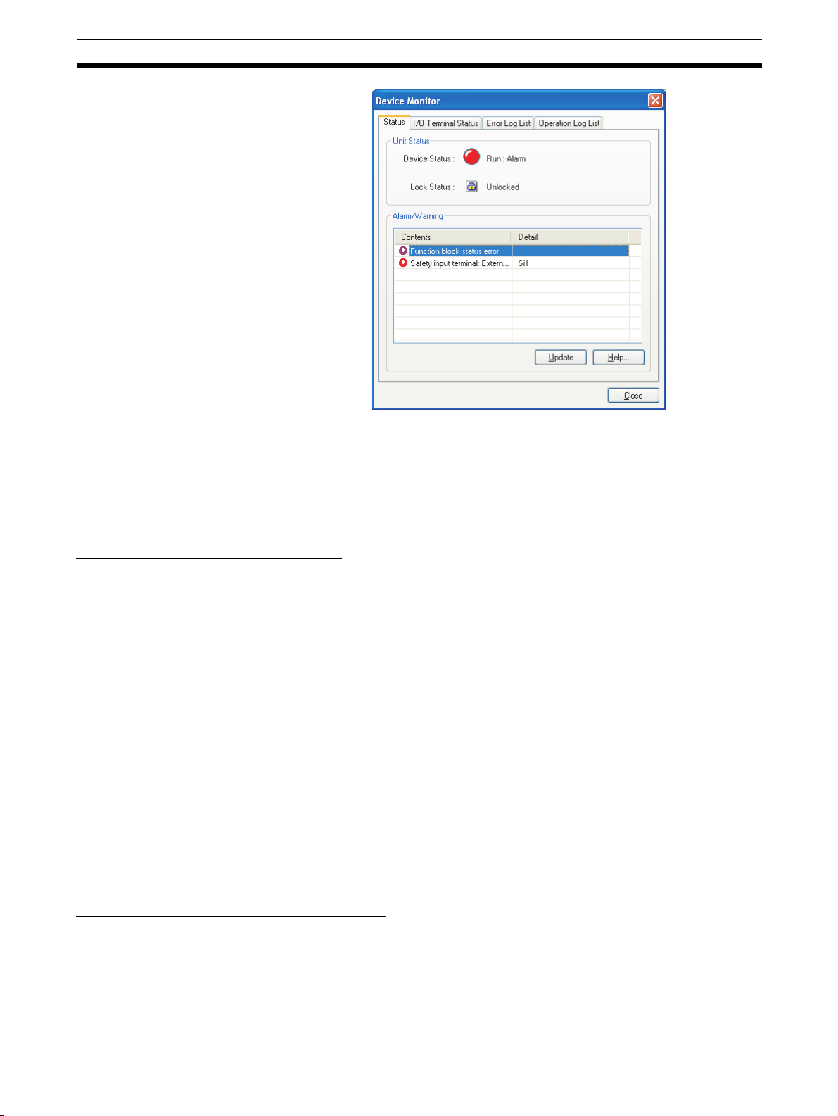
Identifying Devices with Errors Using Online Monitoring
• You can detect errors, such as power supply voltage drops, faulty I/O wiring, and Safety Relay welding faults, and then check the cause and countermeasures.
6
Page 33
Overview and Features of the G9SP-series Controller Section 1-1
Force-setting/Force-resetting
• Force-setting/resetting lets you turn the I/O tags ON and OFF in the program regardless of whether I/O devices and communications data are ON
or OFF. During system development, programming can be debugged
without I/O devices and remote communications. This also enables efficient checking of output wiring.
Improved Maintenance Efficiency
The G9SP-series Controller is equipped with a variety of functions to minimize
system downtime if an error occurs. This helps improve production efficiency
by preventing unnecessarily stopping the system.
Continued Operation of Error-free Areas
Even if an error occurs, the G9SP-series Controller will immediately identify
the location of the error and stop only the parts affected by the error, while
parts without errors will continue to operate. For example, if a short-circuit
fault occurs in I/O wiring, only the outputs related to the Safety Devices that
are connected there will stop.
Information to Identify Causes of Stopping
You can quickly identify the cause of stopping by using the two-color indicators on the G9SP-series Controller as well as the error log and operation log
in the G9SP Configurator.
Backup and Restore Data Using Optional Memory Cassettes
A Memory Cassette can be used when replacing the G9SP-series Controller
or updating the program. This enables easily replacing and restoring the
G9SP-series Controller without directly using the G9SP Configurator.
Access Management Using Passwords
Passwords in the G9SP-series Controller and G9SP Configurator can be used
to prevent unintended changes to the configuration data at the work site.
Access Management Using Device Password
Configuration data that has been downloaded to the G9SP-series Controller
is protected using a password set in the Controller. Changes to configuration
data using the Memory Cassette can also be prohibited.
7
Page 34

Overview and Features of the G9SP-series Controller Section 1-1
Access Management Using Parameter Passwords
Access to project files created by the G9SP Configurator can also be managed using passwords. This prevents unintended changes to project files as
well as disabling access to configuration data uploaded from the G9SP-series
Controller.
8
Page 35

Basic Operating Procedures Section 1-2
1-2 Basic Operating Procedures
Generally, the following procedures are used for operation.
System Design
1. Determining Safety Measures by Conducting Risk Assessment
2. Selecting Safety Devices
3. Designing Device Security
4. Designing Interface with Control Device (Standard PLC)
Section 2 Part Names and Specifications
6-3 Designing Device Security
Section 7 Communications with a Standard PLC
Using an Option Board
Hardware Design
Wiring and safety response performance of
connection I/O devices are verified according to
I/O terminal allocations in the configuration reports.
1. Determining Wiring for Power Supply,
Connected I/O Devices, and Communications
2. Calculating and Verifying Safety Response
Performance
3. Installation and Wiring
Section 2 Part Names and Specifications
Section 3 Calculating Response Performance
Section 4 Installation and Wiring
Software Design
Configuration data is created and debugged on a computer using
the G9SP Configurator.
1. Preparations and Starting the G9SP Configurator
2. Creating Configuration Data
Settings are made for hardware (e.g., unit configuration and I/O
terminal settings), programming, and the system.
3. Displaying and Printing Reports
The settings are given in the configuration report and passed to
the hardware designer.
4. Desktop Debugging
Programming is debugged in advance using offline simulation
and searches.
Section 5 Preparations for Using the G9SP Configurator
Section 6 Creating Configuration Data
Startup and Debugging
The G9SP-series Controller and the computer are connected, and then configuration data is downloaded, debugged, and
checked for correct operation.
1. Connecting Online and Downloading to the G9SP-series Controller
2. Controller Trial Operation (Checking and Debugging Operating Status)
Checking is performed to confirm that the G9SP-series Controller operates as intended by checking wiring using forcesetting/resetting and monitoring program operation.
3. Conducting Safety Validation Testing
Once debugging has been completed, checking is performed to validate that all safety functions are operating correctly.
4. Preparations for Operation
Finally, preparations for operation are performed.
Once the safety confirmation testing has been completed, the configuration data is locked.
Configuration data is backed up to a Memory Cassette to prepare for replacing the G9SP-series Controller
whenever necessary.
A report of the final configuration data is output and stored.
Section 8 Connecting Online and Downloading
to the G9SP-series Controller
Section 10 Checking Operating Status and Debugging
Section 9 Operation and Operating Modes
Section 11 Backup and Restore Data Using
Memory Cassette
Operation, Maintenance, and Inspection
1. Equipment Operation
2. Troubleshooting
3. Inspection and Replacement
Section 11 Backup and Restore Data Using Memory Cassette
Section 12 Inspections and Maintenance
Section 13 Troubleshooting
9
Page 36

Basic Operating Procedures Section 1-2
10
Page 37

Hardware Settings
SECTION 2
Part Names and Specifications
This section provides the names of G9SP-series Controller parts, specifications, and terminal arrangements.
2-1 G9SP-series Controllers . . . . . . . . . . . . . . . . . . . . . . . . . . . . . . . . . . . . . . . . . 12
2-1-1 Part Names and Indicators . . . . . . . . . . . . . . . . . . . . . . . . . . . . . . . . 12
2-1-2 Terminal Arrangements . . . . . . . . . . . . . . . . . . . . . . . . . . . . . . . . . . 16
2-1-3 General Specifications . . . . . . . . . . . . . . . . . . . . . . . . . . . . . . . . . . . 17
2-1-4 I/O Specifications . . . . . . . . . . . . . . . . . . . . . . . . . . . . . . . . . . . . . . . 17
2-1-5 Safety Inputs. . . . . . . . . . . . . . . . . . . . . . . . . . . . . . . . . . . . . . . . . . . 20
2-1-6 Safety Outputs . . . . . . . . . . . . . . . . . . . . . . . . . . . . . . . . . . . . . . . . . 34
2-2 Expansion I/O Units . . . . . . . . . . . . . . . . . . . . . . . . . . . . . . . . . . . . . . . . . . . . 40
2-2-1 Part Names and Indicators . . . . . . . . . . . . . . . . . . . . . . . . . . . . . . . . 40
2-2-2 Terminal Arrangements . . . . . . . . . . . . . . . . . . . . . . . . . . . . . . . . . . 42
2-2-3 I/O Specifications . . . . . . . . . . . . . . . . . . . . . . . . . . . . . . . . . . . . . . . 45
2-2-4 Current Consumption . . . . . . . . . . . . . . . . . . . . . . . . . . . . . . . . . . . . 47
2-3 Option Units . . . . . . . . . . . . . . . . . . . . . . . . . . . . . . . . . . . . . . . . . . . . . . . . . . 48
2-3-1 RS-232C Option Board (CP1W-CIF01). . . . . . . . . . . . . . . . . . . . . . 48
2-3-2 Ethernet Option Board (CP1W-CIF41) . . . . . . . . . . . . . . . . . . . . . . 49
2-3-3 Memory Cassette (CP1W-ME05M) . . . . . . . . . . . . . . . . . . . . . . . . . 50
11
Page 38

G9SP-series Controllers Section 2-1
k
y
r
2-1 G9SP-series Controllers
This section provides the names of Controller parts, I/O specifications, and
terminal arrangements. Refer to 4-1 Installation for dimensions and weights
and 4-2 Wiring for wiring diagrams.
2-1-1 Part Names and Indicators
Nomenclature and Functions
G9SP-N10S
(1) Operation Indicators
(6) Option Board Slot
(7) Expansion I/O Unit Connector
G9SP-N10D
G9SP-N20S
(5) Memory Cassette Slot
(2) USB Port
(3) Push Switch
(4) DIP Switch
(1) Operation Indicators
(6) Option Board Slot
(8) I/O Indicators
(9) Terminal Bloc
(8) I/O Indicators
(8) I/O Indicators
(9) Terminal Block
(7) Expansion I/O Unit Connecto
(9) Terminal Block
12
(2) USB Port
(3) Push Switch
(4) DIP Switch
(5) Memor
Cassette Slot
(8) I/O Indicators (9) Terminal Block
Page 39

G9SP-series Controllers Section 2-1
No. Name Function
1 Operation Indicators These indicators can be used to check the operating status of the G9SP-series Control-
2
USB Port
3 Push Switch This switch is used for the following operations.
4 DIP Switch The DIP switch is used to back up data to a Memory Cassette and to set the serial com-
*1
ler.
Connect a USB cable to this port to connect to a computer to set up and monitor the
G9SP-series Controller from the G9SP Configurator. A commercially available USB
cable can be used. The G9SP-series Controller end of the USB cable must be a B-type
male connector.
5-2-2 Installing the USB Driver
1. Backing up data to a Memory Cassette and restoring data from a Memory Cassette
2. Displaying the current configuration ID on the I/O indicators
SECTION 11 Backup and Restore Data Using Memory Cassette
munications baud rate.
No. Name Description Default
Pin 1 Do not use. Leave set to OFF OFF
Pin 2
Pin 3
Do not use. Leave set to OFF
Baud rate
*2
OFF: 9,600 bps
OFF
OFF
ON: 115,200 bps
Pin 4 Backup from
G9SP-series
Controller to
Memory Cassette
If the G9SP-series Controller is
started while this pin is ON, the
data will be backed up from the
G9SP-series Controller to the
Memory Cassette (MC).
Leave this pin turned OFF during
normal operation.
OFF
5 Memory Cassette Slot The Memory Cassette is mounted in this slot. A slot cover is attached when the G9SP-
series Controller is shipped from the factory.
1-1-2 Basic System and Configuration Devices
2-3 Option Units
SECTION 11 Backup and Restore Data Using Memory Cassette
6 Option Board Slot One Option Board can be mounted in this slot.
1-1-2 Basic System and Configuration Devices
2-3 Option Units
7 Expansion I/O Unit Con-
nector
8 I/O Indicators These indicators show the status of the built-in I/O terminals.
9 Terminal Block Connect the power supply and I/O devices to the terminal block.
Up to two CP-series Expansion I/O Units can be connected.
1-1-2 Basic System and Configuration Devices
2-2 Expansion I/O Units
*1 The USB cable must be 3 m or less in length.
*2 The baud rate can be set on this DIP switch pin with unit version 2.0 or
later.
13
Page 40

G9SP-series Controllers Section 2-1
Operation Indicators
This section describes the operation indicators that are provided on the
G9SP-series Controller. Refer to sections on individual functions for details.
: OFF : Flashing : ON
Indicator Color Status Description
MS
MS (Module Status) Green Operating (RUN Mode)
Idle (IDLE Mode)
FORCE
LOCK
ERR/ALM
MC
COMM
FORCE (force-set/
reset status)
LOCK (configuration
lock)
ERR/ALM (error status)
Red Critical fault status (fatal error)
Abort status (non-fatal error, such as connection of an unsupported Unit)
Green/Red The G9SP-series Controller is being initialized or is waiting for
--- Power is not being supplied to the internal circuits or a Memory
Reference SECTION 9 Operation and Operating Modes
Yellow Force-setting/resetting is enabled (Force Mode).
Reference SECTION 9 Operation and Operating Modes
Yellow The configuration is valid and locked.
Reference 9-4 Changing the Configuration Data
Red A fatal error has occurred.
configuration.
Cassette operation is in progress.
Force Mode is not being used or a Memory Cassette operation
is in progress.
10-3 Debugging in Force Mode
The configuration is valid and unlocked.
There is no valid configuration or a Memory Cassette operation
is in progress.
A non-fatal error has occurred.
14
MC (Memory Cassette)
COMM (USB communications)
Operation is normal.
Reference SECTION 13 Troubleshooting
Yellow One of the following Memory Cassette operations has been
completed.
1. Backing up data to the Memory Cassette
2. Restoring data from the Memory Cassette
This indicator lights yellow when the operation ends normally.
If the operation ends in an error, this indicator lights yellow and
the ERR/ALM indicator lights red.
The G9SP-series Controller is waiting to start a Memory Cassette operation.
0.5 s
Data is being written to or from the Memory Cassette.
0.25 s
A Memory Cassette operation is not being performed.
Reference SECTION 11 Backup and Restore Data Using Memory Cas-
Yellow USB communications are in progress (data is being sent or
sette
received).
USB communications are not in progress.
Page 41

G9SP-series Controllers Section 2-1
Precautions for Safe Use
If the MC indicator is flashing at 0.25-s intervals, it indicates that the Memory
Cassette is being accessed (read or written).
Do not turn OFF the internal circuit power supply to the G9SP-series Controller or remove the Memory Cassette until the indicator stops flashing. If the
power supply is turned OFF while data is being accessed, data in the G9SPseries Controller may be corrupted or lost.
I/O Indicators
This section describes the I/O indicators that are provided on the G9SPseries Controller.
Self-diagnosis is performed to detect circuit failures and other circuit problems
for Safety Input and Safety Output terminals. If errors are detected in this selfdiagnosis, the terminal where the error occurred will be shown by a red indicator.
: OFF : Flashing : ON
Indicator name Color Status Meaning
OUT PWR (Output Power) Green The output power supply is normal.
Si0 to Sin
n: Terminal number of Safety
Input terminal
So0 to Son
n: Terminal number of Safety
Output terminal
O0 to On
n: Terminal number of Standard Output terminal
• The output power supply is not being supplied.
• The Controller is being initialized.
• Configuring Mode
• A fatal error has occurred.
Yellow The input signal is ON.
Red • An error was detected in an input circuit.
--- • The input signal is OFF.
Yellow The output signal is ON.
Red • An error was detected in an output circuit.
--- The output signal is OFF.
Yellow The output signal is ON.
• A discrepancy error (input data mismatch) was detected for Dual Channel Mode settings.
• If an error is detected for a Memory Cassette operation, the terminal
number indicator that corresponds to the error code will light.
An error was detected in other terminal in Dual Channel Mode (with no
error for this input).
• Initialization is in progress.
• Waiting for configuration.
• A fatal error occurred.
• A dual channel violation (output data mismatch) was detected in Dual
Channel Mode.
An error was detected in other terminal in Dual Channel Mode (with no
error for this input).
The output signal is OFF.
!WARNING Serious injury may possibly occur due to loss of required safety functions. Do
not use indicators on the G9SP-series Controller for safety operations.
15
Page 42

G9SP-series Controllers Section 2-1
2-1-2 Terminal Arrangements
G9SP-N10S
Si1
Si3
Si5
Si7
Top
(17 pins)
V1 G1
NC
Si0
Si2
Si4
Si6
Si8
Si9
T1 T3
T0
T2
Bottom
(14 pins)
G9SP-N10D
Top
(24 pins)
Bottom
(19 pins)
G9SP-N20S
Top
(24 pins)
Bottom
(19 pins)
Internal Circuits and Wiring Diagram
USB
D+
D−
NC
V2
V1 G1
NC NCSi0
V2
V1 G1
NC
NC
V2
Internal
Circuit
So0
So1
G2
Si1
So0NC
So1
G2
Si1
So0
G2 So1
So2
So3
Si3
Si2
So2
So4
So3
Si3
Si2
So2
So4
So3
Input Circuit
Output Circuit
O0
Si4
Si4
Safety
Test Output
Safety
NC NC
O1O2O3
Si5
So6
So5
Si5
So6
So5
Circuit
NC
Si7
Si9
Si6
Si8
So8
So9
So7
Si7
Si9
Si6
Si8
So7NCNC T3T4T5
NC
NC
So10
So11
Si11
Si10
T0T1T2
NCNCT0
So12
So13
Si13
Si12
V1
G1
Si0
Si19
T0
T5
V2
G2
So0
So7
So14
Si14
T1
So15
Si15
Si16
24 VDC
L
L
T2T3T4
Si17
Si18
T5
Si19
NCSi0
Terminals
16
Standard
Output Circuit
O0
O3
L
L
Terminals Function
V1/G1 Power supply terminals for internal and input circuits (24 VDC).
V2/G2 Power supply terminals for output circuits (24 VDC).
NC Not used (Do not connect)
Si0 to Si19 Safety Input terminals
T0 to T5 Test Output terminals
So0 to So15 Safety Output terminals
O0 to O3 Standard Output terminals
Page 43

G9SP-series Controllers Section 2-1
2-1-3 General Specifications
Item Specification
Power supply voltage (V1, V2) 24 VDC (20.4 to 26.4 VDC −15%+10%)
Current consumption
Insulation class Class III (SELV)
Overvoltage category II
Noise immunity Compliant with IEC 61131-2
Vibration resistance
Shock resistance
Mounting DIN Track (IEC 60715 TH35-7.5 / TH35-15) or
Ambient operating temperature 0 to 55°C
Ambient operating humidity 10% to 90% (with no condensation)
Ambient storage temperature −20 to 75°C
Atmosphere No corrosive gas
Operating altitude 2,000 m max.
Pollution degree Pollution degree 2
Degree of protection IP20 except terminal blocks
Terminal screws M3 self-rising screws
*1
400 mA (V1: 300 mA, V2: 100 mA) (N10S)
500 mA (V1: 300 mA, V2: 200 mA) (N10D)
500 mA (V1: 400 mA, V2: 100 mA) (N20S)
5 to 8.4 Hz: 3.5 mm, 8.4 to 150 Hz: 9.8 m/s
2
147 m/s
M4 screws
: 11ms
2
*1 The current consumption of external devices is not included.
2-1-4 I/O Specifications
I/O Capacities
Item G9SP-N10S G9SP-N10D G9SP-N20S
Safety Inputs 10 points 10 points 20 points
Safety Outputs 4 points 16 points 8 points
Test Outputs 4 points 6 points 6 points
Standard Outputs 4 points - -
Safety Input Specifications
Item Specification
Input type Sinking inputs (PNP compatible)
Input current 6 mA
ON voltage 11 VDC min. (between inputs and G1)
OFF voltage 5 VDC max. (between inputs and G1)
OFF current 1 mA max.
Precautions for Correct Use
Safety devices with semiconductor outputs, such as safety light curtains,
sometimes provide a pulse output that is used to detect wiring errors.
Observe the following when connecting a safety device with a semiconductor
output to a Safety Input terminal on the G9SP-series Controller.
• OFF pulse width when semiconductor output is ON: 700 µs max.
17
Page 44

G9SP-series Controllers Section 2-1
700 µs max.
• ON pulse width when semiconductor output is OFF: 30 µs max.
30 µs max.
Test Output Specifications
Item Specification
Output type Sourcing outputs (PNP)
Rated output current G9SP-N10S T0, T1: 60 mA max.
T2: 30 mA max.
T3: 300 mA max.
T0-2 total: 60mA max.
G9SP-N10D T0, T1, T2: 60 mA max.
T3: 300 mA max.
T4, T5: 30 mA max.
T0-2, T4-5 total: 60mA max.
G9SP-N20S T0, T1, T2: 100 mA max.
T3: 300 mA max.
T4, T5: 30 mA max.
T0-2, T4-5 total: 120 mA max.
ON residual voltage 1.8 V max. (between test outputs and V1)
Leakage current 0.1 mA max.
*1
*2
*2
*1
*2
*1
Safety Output Specifications
*1 Connection to an OMRON D40A or D40Z Non-Contact Switch is possi-
ble.
*2 With the Muting Lamp Output (open circuit detection)
Item Specification
Output type Sourcing outputs (PNP)
Rated output current 0.8 A max./point
1.6 A max./4 points (N10S or N20S)
1.2 A max./4 points (N10D)
ON residual voltage 1.2 V max. (between outputs and V2)
OFF residual voltage 2 V max.
Leakage current 0.1 mA max.
*2
*1
*1 Total current for So0 to So3 and So4 to So7.
*2 Total current for So0 to So3, So4 to So7, So8 to So11, and So12 to So15.
Precautions for Safe Use
When a Safety Output is set as a pulse output, make sure that the connected
device does not malfunction for the OFF pulse (pulse width: 640 µs).
18
Page 45

G9SP-series Controllers Section 2-1
t
Standard Output Specifications of G9SP-N10S
Item Specification
Output type Sourcing outputs (PNP)
ON residual voltage 1.5 V max. (between outputs and V2)
Rated output current 100mA max.
Input Wiring
Devices with Contact Outputs
A devices with a contact output, such as an emergency stop pushbutton or
safety limit switch, is input to the G9SP-series Controller using a Safety Input
terminal (Si) and Test Output terminal (To).
G9SP
V1
To
Si
G1
24 VDC
6 mA typ
The total length of cable connected to one Test Output must be 600 m or less.
G9SP
To 0
Si0
Si1
L1
2
L
3
L
4
L
L1+L2+L3+L4 600m
Devices with PNP Semiconductor Outputs (Current-sourcing Outputs)
The signal from a device with a PNP semiconductor output, such as a light
curtain, is input to a Safety Input terminal (Si). Check the specifications of the
connected device for the maximum cable length.
G9SP
V1
Si
G1
24 VDC
Device with PNP
semiconductor outpu
6 mA typ
19
Page 46

G9SP-series Controllers Section 2-1
Output Wiring
• Refer to the following information when connecting output devices.
• The cable length from an output terminal to the output device must be 100
m or less.
G9SP
24 VDC
V2
0.8 A max.
So
L
G2
2-1-5 Safety Inputs
This section describes the Safety Input functions of the G9SP-series Controller’s Safety I/O functions. The G9SP-series Controller diagnoses the external
devices connected to Safety Input terminals.
Connectable External Devices
The following table lists the connectable external devices (Safety Devices and
Standard Devices).
Safety Devices with
mechanical contacts
Safety Devices with semiconductor outputs
Standard Devices Limit switches and muting sensors
The following OMRON Safety Devices can be connected directly without special controllers.
OMRON Single Beam
Safety Sensor
OMRON Non-contact
Switch
OMRON Safety Mat UM (Conforms to Safety Category 3 and PLd.)
Type Examples
Emergency stop switches, safety limit switches, safety
switches, enable switches, and 2-hand switches
Safety curtains and laser scanners
Type Model and category/PL
E3ZS and E3FS (Conforms to Safety Category 2 and
PLc.)
D40A (Conforms to Safety Category 3 and PLd.)
D40Z (Conforms to Safety Category 4 and PLe.)
20
Page 47
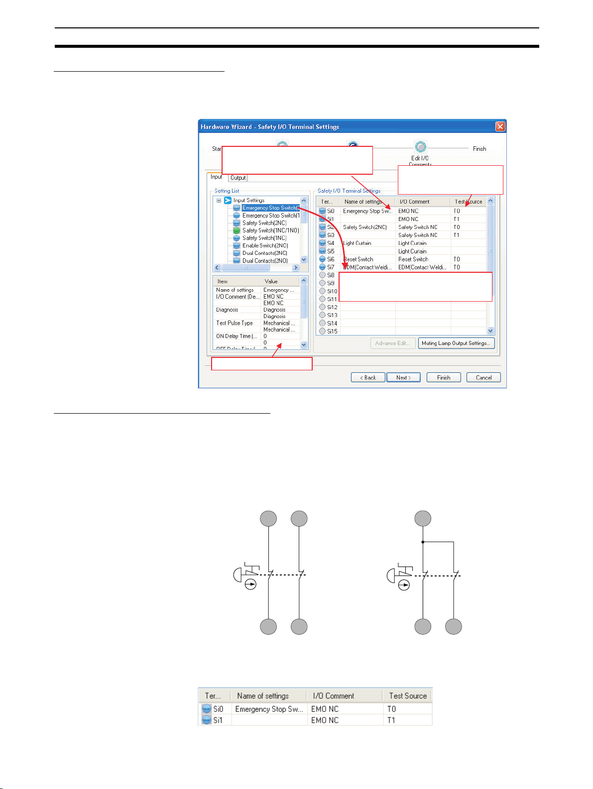
G9SP-series Controllers Section 2-1
Setting Safety Input Terminals
A Safety Input terminal on the G9SP-series Controller can be easily set by
selecting the connected external device on the G9SP Configurator. (For
details, refer to 6-2-2 Hardware Settings.)
The selected connection devices are displayed.
I/O comments are treated as names and can be
used in the program.
You drag and drop connected devices to the
terminals to which there are connected. This
completes the settings for Safety Input terminals.
These are the Test Output
terminals that are used together
with the Safety Input terminals.
The settings are displayed.
External Device Connection Examples
Connecting Safety Devices with Mechanical Contacts
Connecting an emergency stop switch is described here as an example of
connecting Safety Devices with mechanical outputs.
Wiring Example
If redundant emergency stop switches are used, a Test Output terminal is also
used.
T0 T1
11 21
12
Si0
Circuit for Detecting Short Circuits
between Input Signals
Si1
22
T0
11 21
12
Si0
Circuit for Which Detecting Short Circuits
between Input Signals Is Not Necessary
22
Si1
G9SP Configurator Setting Example
21
Page 48

G9SP-series Controllers Section 2-1
Connecting Safety Devices with Semiconductor Outputs
Connecting a safety light curtain is described here as an example of connecting Safety Devices with semiconductor outputs.
Wiring Example
A 24-VDC semiconductor output, such as the OSSD output from the safety
light curtain, is input.
Errors in the OSSD output signal line are detected by the externally connected device.
Safety
Light Curtain
Emitter
Receiver
24 VDC
0V
0V
Si0
Si1
G9SP Configurator Setting Example
Connecting an OMRON E3ZS/E3FS Single Beam Safety Sensor
This section describes connecting an OMRON E3ZS/E3FS Single Beam
Safety Sensor.
Wiring Example
The OSSD 24-VDC semiconductor output from the Single Beam Safety Sensor is input.
Single Beam
Safety Sensor
24 V
0 V
Control output 1 (OSSD 1)
Control output 2 (OSSD 2)
Receiver
Light transmitter
22
0 V (Blue)
T3
Si0
24 VDC
0 V
1
L
L2
24 V (Brown)
G9SP Configurator Setting Example
Test input (Pink)
Control output (Black)
Mode (Pink)
24 V (Brown)
0 V (Blue)
L1 + L2 ≤ 100 m
Page 49

G9SP-series Controllers Section 2-1
Precautions for Correct Use
• Only one E3ZS/E3FS Single Beam Safety Sensor can be connected to a
G9SP-series Safety Controller with unit version 1.0 or unit version 1.1.
The maximum number of E3ZS/E3FS Single Beam Safety Sensors that can
be connected to a G9SP-series Safety Controller with unit version 2.0 or
later is as follows:
G9SP-N10S: 4 (1 Sensor × 4 systems)
G9SP-N10D/20S: 6 (1 Sensor × 6 systems)
• The total wiring length (L1 + L2 in the above figure) for the E3ZS/E3FS Single Beam Safety Sensor must be 100 m or less.
• The E3ZS/E3FS Single Beam Safety Sensor can be used in a Safety Category 2 or lower, or PLc or lower application. It cannot be used in a Safety
Category 3 or higher, or PLd or higher application.
• If you use more than one Single Beam Safety Sensor, it may not be possible to detect short circuits between wires. To satisfy safety category 2, you
must protect the cables to the Single Beam Safety Sensors from external
damage. Use ducts, separate the cables for each system, or implement
other measures to protect the cables from external damage when you connect the Single Beam Safety Sensors. You can also provide protection
against short circuits by using special cables (XS2F).
• The test period for a Single Beam Safety Sensor test is as given below. Use
the value as reference to determine conformance with standards for your
system.
G9SP-N10S: 112 × Cycle time (ms)
G9SP-N10D/20S: 168 × Cycle time (ms)
23
Page 50

G9SP-series Controllers Section 2-1
Connecting an OMRON D40A or D40Z Non-contact Switch
This section describes connecting an OMRON D40A or D40Z Non-contact
Switch.
Wiring Example
The non-contact switch output (black line) from the OMRON D40A or D40Z
Non-contact Switch is input to a Safety Input terminal. This is a one-line signal. When connecting it to the G9SP-series Controller, branch it, as shown for
Si0 and Si1 in the following diagram.
Only one Test Output terminal is used. Connect the Non-Contact Switch input
(white line). The inputs for up to 15 Non-Contact Switches can be connected
in series to one Test Output terminal.
n Switches (15 max.)
Black
Brown
White
Black
Brown
Blue
White
2
L
Blue
White
Black
Brown
Blue
L
n+1
0 V
L
n+2
24 VDC
Si0
Si1
T4
L
L
1
G9SP Configurator Setting Example
1
+
L2+
+
L
n+1
+
L
n+2
≤ 100m
24
Page 51

G9SP-series Controllers Section 2-1
Precautions for Correct Use
• The maximum number of Switches that can be connected to a G9SP-series
Controller is given below.
G9SP-N10S: 15 (15 × 1 system)
G9SP-N10D/20S: 30 (15 × 2 system)
• The following Test Output terminals must be used to connect to the D40A or
D40Z Non-contact Switch. Do not connect any other Test Output terminals.
G9SP-N10S: T2
G9SP-N10D/20S: T4 and T5
• The total wiring length (L1 + L2 +…+ L
D40Z Non-contact Switch must be 100 m or less.
• Mechanical contacts and sensors cannot be used on D40A/D40Z Non-contact Switch input lines.
• The D40A Non-contact Switch can be used in a Safety Category 3 or lower,
or a PLd or lower application. It cannot be used in an Safety Category 4 or
PLe application.
• The D40Z Non-contact Switch can be used in a Safety Category 4 or lower,
or a PLe or lower application.
in the above figure) for the D40A/
n+2
Additional Information
If you use a standard model of the D40A/D40Z (with a cable) or if you use
branch connections with the XS2F/XS2W, multiple the cable lengths by two
when you calculate the total wiring length.
25
Page 52

G9SP-series Controllers Section 2-1
Connecting an OMRON UM Safety Mat
This section describes connecting an OMRON UM Safety Mat.
Wiring Example
A Safety Output from the UM Safety Mat is connected to a Safety Input terminal. For the UM, only 1 system can be set and up to 12 Mats can be connected in series.
T3T2
L1
Blue White
Safety Mat 1
Brown
White
Brown
Si1
L2
L3
In this example,
1 + L2 + L3
L
≤
100 m.
Safety Mat 2
This wiring example if for
connecting two UM Safety Mats.
Black
Blue
Black
Si0
G9SP Configurator Setting Example
Precautions for Correct Use
• The maximum number of Mats that can be connected to a Controller is
given below.
12 Mats (12 Mats × 1 system)
2
• The total surface area for the UM Safety Mats must be 18 m
or less.
• The total wiring length for the UM Safety Mat must be 100 m or less.
• The UM Safety Mat can be used in a Safety Category 3 or lower, or a PLd
or lower application. It cannot be used in an Safety Category 4 or PLe application.
26
Additional Information
If you use the cable provided with a UM Safety Mat or the UMEC-×× Extension Cable, multiple the cable lengths by two when you calculate the total wiring length.
Page 53

G9SP-series Controllers Section 2-1
Connecting an OMRON MC3 Mat Controller
This section describes connecting an OMRON MC3 Safety Mat Controller.
Wiring Example
A Safety Output from the MC3 Safety Mat Controller is connected to Safety
Input terminals.
T0 T1
2313
MC3 Safety Mat Controller
14
Si0 Si1
24
G9SP Configurator Setting Example
Precautions for Correct Use
Set the ON delay time of the Safety Input terminals to 30 ms or higher.
27
Page 54

G9SP-series Controllers Section 2-1
Functions of Safety Input Terminals
This section describes the functions of the Safety Input terminals on the
G9SP-series Controller. The following functions are allocated automatically
when the external devices to connect are selected from the G9SP Configurator.
The values that are read from the Safety Input terminals are passed to the program
only after evaluating them for the Safety Input functions.
Safety Input
terminals
Safety Input
functions
Safety Input
terminals
Self-diagnosis
Test pulse evaluation
A pulse is output at a specific
interval to detect failure of or
wiring errors in the externally
connected device. The test
mode that is used depends
on the Safety Device.
Dual channel evaluation
When Safety Input terminals
are used as dual channels,
the two inputs are checked for
consistency.
Other Functions
Safety Output
functions
Safety Output
terminals
No diagnosis
Device with mechanical contacts
Single Beam Safety Sensor
Non-contact Switch
Safety Mat
Single channel
There is no redundancy.
Dual channel equivalent
Two inputs are checked to make sure they
have the same value.
Dual channel complementary
Two inputs are checked to make sure they
have different values.
Safety Mat
A two-input logic check is made for a Safety Mat.
ON delay
Input filters
ON delays and OFF delays can be set to prevent malfunctions
caused by noise or by chattering of externally connected devices.
Error notification
Self-diagnosis of Safety Input
terminals provides notification of
the locations and causes of
errors.
OFF delay
Checking with I/O indicators
Yellow indicators show the input is ON and normal. Red indicators show errors.
Checking with the G9SP Configurator
The G9SP Configurator can be used to check error causes (e.g., failure of externally
connected devices and wiring errors, such as short-circuits or ground faults).
Checking with Option Board Communications
The same information that is available on the G9SP Configurator can be sent to a
Standard PLC that is connected through an Option Board.
28
Page 55

G9SP-series Controllers Section 2-1
Test Pulse Evaluation
A test pulse with a specific period is output on the 24-V power line from a Test
Output terminal to detect wiring errors and failure of the externally connected
device. The following parameters are also used.
• Diagnosis
• Test source
• Test Mode
Diagnosis
Combining Si0 and T0
G9SP
V1
G1
T0
Si0
Diagnosis is set according to the type of external device that is connected to
the Safety Input terminal.
Setting Description
No diagnosis A test pulse from the Test Output terminal is not output for diagno-
sis. This setting is used for Safety Devices with semiconductor outputs, such a Safety Light Curtain, and for Standard Devices.
Diagnosis A test pulse from the Test Output terminal is output for diagnosis.
The mode of the Test Output to use as the test source is selected
according to the Safety Device that is connected.
For example, it is possible to detect a short-circuit with
the positive side of the power supply for the input signal.
24V
0V
External contacts
The test pulse is output on the 24-V power line
from Test Output terminal T0 and the
Controller monitors Safety Input terminal Si0
to see if the test pulse is returned normally.
Test Source
This parameter determines the Test Output terminal to use when the Diagnosis Parameter is set to Diagnosis. The Test Output terminal is automatically
assigned by the G9SP Configurator, but it can be changed to any Test Output
terminal.
Precautions for Correct Use
The following Test Output terminals must be used to connect to the D40A or
D40Z Non-contact Switch. Do not connect any other Test Output terminals.
G9SP-N10S: T2
G9SP-N10D/20S: T4 and T5
29
Page 56

G9SP-series Controllers Section 2-1
Test Mode
When the Diagnosis parameter is set to Diagnosis, the following setting is
required to output a test pulse that is suitable for the external device.
Setting Function
Mechanical contacts
Single Beam
Safety Sensor
Non-contact
Switch
Safety Mat An OMRON UM Safety Mat is connected. Test signals for diagnos-
The test pulse is connected to a device with mechanical contacts.
The Safety Input terminal’s Test Output signal (pulse output) is
input through the mechanical contact device.
The following can be detected: Contact of the input signal line with
the positive side of the power supply line, ground faults, and shortcircuits to the other input signal lines.
An OMRON E3ZS/E3FS Single Beam Safety Sensor is connected.
A test signal for Single Beam Safety Sensor diagnosis is output.
An OMRON D40A or D40Z Non-contact Switch is connected. Test
signals for the D40A or D40Z will be output.
ing the Safety Mat will be output.
Dual Channel Evaluation
Input safety terminals can be used as dual channels (one pair) for the G9SPseries Controller. This function evaluates the data for two inputs to check for
discrepancy. The following parameters are also used.
• Single/Dual Setting
• Discrepancy Time
Single/Dual Setting
Single Channel The Safety Input terminals are used as independent Safety Input
Dual Channel
Equivalent
Dual Channel
Complementary
Safety Mat The Safety Input terminals are used as Safety Mat Safety Input
Discrepancy Time
For two inputs set in a Dual Channel Mode, the time is monitored from a
change in the value of one input to a change in the value of the other input. An
error occurs if the value of the other input does not change within the set discrepancy time.
The discrepancy time can be set in increments of 10 ms between 0 (disabled)
and 65,530 ms.
The discrepancy time cannot be set in Single Channel Mode.
Relationship between Input Tags
The data that is input to Safety Input terminals is evaluated as shown in the
following table. The results of this evaluation are reflected in the input tags
that are used in the program.
Single Channel 0 0 Inactive (OFF)
Setting Description
terminals.
The Safety Input terminals are used as a dual channel equivalent
pair.
The Safety Input terminals are used as a dual channel comple-
mentary pair.
pair.
Single/dual Input signal from
Safety Input
terminal
Si (n) Si (n+1)
1 1 Active (ON)
Value after
evaluation
Meaning of status
30
Page 57

G9SP-series Controllers Section 2-1
Single/dual Input signal from
Dual Channel
Equivalent
Dual Channel
Complementary
Safety Input
terminal
Si (n) Si (n+1) Si (n) Si (n+1)
0000Inactive (OFF)
0 1 0 0 Discrepant status
1 0 0 0 Discrepant status
1111Active (ON)
0 0 0 1 Discrepant status
0101Inactive (OFF)
1010Active (ON)
1 1 0 1 Discrepant status
Value after
evaluation
Meaning of status
n = Even number
Single/dual Status of
Safety Mat
Safety Mat No load 1 1 Active (ON)
With load 0 0 Inactive (OFF)
■ Operation for Dual Channel Equivalent Inputs: Normal Operation
Si0 terminal
Value after evaluation Meaning of status
Si (n) Si (n+1)
Si1 terminal
Discrepancy Time
I/O tag
Si0
I/O tag
Si1
■ Operation for Dual Channel Equivalent Inputs: Discrepancy Error
Si0 terminal
Si1 terminal
Discrepancy Time
I/O tag
Si0
I/O tag
Si1
Discrepancy Time
Discrepancy Time
31
Page 58

G9SP-series Controllers Section 2-1
y
Input Filters
ON delays and OFF delays can be set to prevent malfunctions caused by
noise or by chattering of externally connected devices.
ON delays and OFF delays can be set for each terminal from 0 to 1,000 ms.
The effect of chattering from external devices can be reduced more by
increasing the delay time, but this will slow the response to input signals.
Limit switch or other input
I/O tag
Error Notification
T: ON delay
Precautions for Correct Use
• The ON and OFF delays can be set only as multiples of the cycle time of
the G9SP-series Controller. If the cycle time changes, e.g., when the program is changed, the ON and OFF delay times will also change.
Example: Delays for a cycle time of 5 ms: ON delay of 10 × 5 ms = 50 ms
and OFF delay of 5 × 5 = 25 ms
Delays after changing cycle time to 6 ms: ON delay of 10 × 6 ms
= 60 ms and OFF delay of 5 × 6 = 30 ms
• The OFF delay time will affect the safety response performance. Add it to
the reaction time. (Refer to 3-2 Reaction Times.)
Self-diagnosis of Safety Input terminals provides notification of the locations
and causes of errors.
The following three methods can be used to check if errors have been
detected.
• Checking with the I/O indicators on the Front of the G9SP-series Controller
The G9SP-series Controller will light or flash the I/O indicators on the front
panel if an error is detected in the Safety Input terminals. This lets you
identify the terminal where the error was detected. Refer to 2-1-1 Part
Names and Indicators for information on the indicator patterns.
• Checking with the G9SP Configurator
If the G9SP Configurator is connected online when an error has been de-
tected in the Safety Input terminals, the terminal where the error was detected and the cause of the error can be checked. Refer to 10-1 Monitoring
Devices for the procedures and displays for using the G9SP Configurator.
• Checking with Option Board Communications
Option Board communications can be used when an error has been de-
tected in the Safety Input terminals to monitor the error location and error
cause from a Standard PLC. Refer to SECTION 7 Communications with a
Standard PLC Using an Option Board for detailed specifications on communications procedures and data for Option Boards.
T: OFF dela
32
Page 59

G9SP-series Controllers Section 2-1
Operation at Error Detection
When the G9SP-series Controller detects an error in the Safety Input terminals, the following operations will take place.
• The Safety Input evaluation data that is passed to the program is made
inactive.
• The ERR indicator will flash red and the I/O indicator of the Safety Input
terminal where the error was detected will light red.
If Dual Channel Mode is being used, the I/O indicator for the other terminal will flash red.
• The error will be recorded in the error log.
• Operation will continue.
Resetting Errors
All the following conditions must be met to reset errors that occur in the Safety
Inputs.
• The cause of the error must be removed.
• An inactive signal must be input (e.g., pressing the emergency stop button or opening a door).
33
Page 60

G9SP-series Controllers Section 2-1
2-1-6 Safety Outputs
This section describes the Safety Output functions of the G9SP-series Controllers Safety I/O functions. The G9SP-series Controller diagnoses the external devices connected to Safety Output terminals.
Devices That Can Be Connected
The following table lists the devices that can be connected.
Type Example
Safety Devices with PNP output contacts Safety relays and contactors
Setting Safety Output Terminals
A Safety Output terminal on the G9SP-series Controller can be easily set by
selecting the connected external device on the G9SP Configurator. (For
details, refer to 6-2-2 Hardware Settings.)
The selected connection devices are
displayed. I/O comments are treated as
names and can be used in the program.
The settings are displayed.
You drag and drop connected devices to
the terminals to which they are to be
connected. This completes the settings
for Safety Output terminals.
34
Page 61

G9SP-series Controllers Section 2-1
External Device Connection Examples
Refer to the following information when connecting output devices.
V2
0.8 A max.
G9SP-series
Controller
So0 to So15
L
G2
24 VDC
!WARNING Serious injury may possibly occur due to breakdown of safety outputs or test
outputs. Do not connect loads beyond the rated values to the safety outputs
and test outputs.
!WARNING Serious injury may possibly occur due to loss of required safety functions.
Wire the G9SP-series Controller properly so that the 24VDC line does NOT
touch the outputs accidentally or unintentionally.
!WARNING Serious injury may possibly occur due to loss of required safety functions.
Ground the 0V line of the power supply for external output devices so that the
devices do NOT turn ON when the safety output line or the test output line is
grounded.
!WARNING Serious injury may possibly occur due to loss of required safety functions. Use
appropriate components or devices according to the requirements given in the
following table.
Control device Requirements
Contactor Use a contactor with a forcibly guided mechanism. For feed-
back signals to detect contactor failure, use a device with NC
contacts. For feedback, use a device with NC contacts capable of switching micro-loads of 6 mA at 24 VDC.
Other control device Verify whether the device is appropriate for the required safety
category.
Precautions for Correct Use
• Be sure to separate I/O cables from high-voltage and power lines.
• The cable length from an output terminal to the output device must be
100 m or less.
35
Page 62

G9SP-series Controllers Section 2-1
Functions of Safety Output Terminals
This section describes the functions of the Safety Output terminals on the
G9SP-series Controller. The following functions are allocated automatically
when the external devices to connect are selected from the G9SP Configurator.
The results of program execution are evaluated by the Safety Output functions
and the evaluation results are output from the Safety Output terminals.
Safety Input
terminals
Safety Input
functions
Program
execution
Safety Output
functions
Safety Output
terminals
Self-diagnosis
Test pulse evaluation
A pulse is output at a specific interval
to detect wiring errors in the
externally connected device.
Dual channel evaluation
When Safety Output terminals
are used as dual channels,
the two outputs are checked
for consistency.
Other Functions
Error notification
Self-diagnosis of Safety Output
terminals provides notification of
the locations and causes of
errors.
No diagnosis
Diagnosis
Single channel
There is no redundancy.
Dual channel equivalent
Two outputs are checked to make sure they
have the same value.
Checking with I/O indicators
Yellow indicators show the output is ON and normal. Red indicators show errors.
Checking with the G9SP Configurator
The G9SP Configurator can be used to check error causes (e.g., failure of externally
connected devices and wiring errors, such as short-circuits or ground faults).
Checking with Option Board Communications
The same information that is available on the G9SP Configurator can be sent to a
Standard PLC that is connected through an Option Board.
Test Pulse Evaluation
36
A test pulse with a specific period is output on the 24-V power line from a
Safety Output Terminal to detect wiring errors. This function is achieved with
the following parameter.
• Diagnosis
Page 63

G9SP-series Controllers Section 2-1
Diagnosis
The parameter determines whether test pulse evaluation is used. The errors
that can be detected are determined by the setting of this parameter.
Channel
mode
No Diagnosis
Diagnosis Test pulses
Description
of operation
Test pulses
are not output
when the output is ON.
are output
when the output is ON.
Fault Mode
Contact with positive
side of power line
Output ON Output
OFF
Not detectable
Detectable Detectable Detectable Not detect-
Detectable Detectable Not detect-
Ground faults Short circuits in output wiring
Output ON Output
OFF
able
able
Precautions for Correct Use
• Disconnections can be detected by using the EDM function block.
• It the parameter is set to Diagnosis, OFF pulse signals with a pulse width of
640 µs will be output when the Safety Output is ON to diagnose the output
circuit. Check the input response time of the connected control device to
make sure it will not malfunction due to these OFF pulses.
Short
circuit
when both
outputs
are ON
Not detectable
Detectable Not detect-
Short
circuit
when both
outputs
are OFF
Not detectable
able
Short
circuit
when one
output is
ON and the
other is
OFF
Detectable
Detectable
Dual Channel Mode Setting
The G9SP-series Controller can use Safety Outputs in a Dual Channel Mode.
The following actions will be performed if a Dual Channel Mode is set:
This function is achieved with the following parameter.
Single/Dual Setting
Single channel The Safety Output terminals are used as independent Safety
Dual channel equivalent
• An error will occur if the two outputs from the user program are not equivalent.
• If an error is detected in either of the two output terminals, the outputs to
the external devices are both turned OFF.
• Single/Dual Setting
Setting Description
Input terminals.
The pair of Safety Output terminals are used as Dual Channel
outputs. The outputs will turn ON if the paired Safety Outputs
are both normal.
37
Page 64

G9SP-series Controllers Section 2-1
Relationship between Output Tags
The data of the output tags that are used in the program are output to the
Safety Output terminals according to the single/dual channel setting as shown
below.
Single/dual Output tag value Output signal from
the Safety Output
terminal
So (x) So (x)
Single Channel 0 0 Inactive (OFF)
1 1 Active (ON)
Meaning of status
Troubleshooting
Single/dual Output tag value Output signal from
the Safety Output
terminal
So (n) So (n+1) So (n) So (n+1)
Dual channel
equivalent
0 0 0 (OFF) 0 (OFF) Inactive (OFF)
0 1 0 (OFF) 0 (OFF) Output data error
1 0 0 (OFF) 0 (OFF) Output data error
1 1 1 (ON) 1 (ON) Active (ON)
Meaning of status
(OFF)
(OFF)
n = Even number
Self-diagnosis of Safety Output terminals provides notification of the locations
and causes of errors. The following three methods can be used to check if
errors have been detected.
■ Checking with the I/O indicators on the Front of the G9SP-series
Controller
The G9SP-series Controller will light or flash the I/O indicators on the front
panel if an error is detected in the Safety Output terminals. This lets you identify the terminal where the error was detected. Refer to 2-1-1 Part Names and
Indicators for information on the indicator patterns.
■ Checking with the G9SP Configurator
If the G9SP Configurator is connected online when an error has been
detected in the Safety Output terminals, the terminal where the error was
detected and the cause of the error can be checked. Refer to 10-1 Monitoring
Devices for the procedures and displays for using the G9SP Configurator.
38
■ Checking with Option Board Communications
Option Board communications can be used when an error has been detected
in the Safety Output terminals to monitor the error location and error cause
from a Standard PLC. Refer to SECTION 7 Communications with a Standard
PLC Using an Option Board for detailed specifications on communications
procedures and data for Option Boards.
Page 65

G9SP-series Controllers Section 2-1
Operation at Error Detection
The G9SP-series Controller performs the following actions if an error is
detected in the Safety Output terminals:
• The outputs to external devices are immediately made inactive regardless
of the status of the user program.
• The ERR indicator will flash red and the I/O indicator of the Safety Output
terminal where the error was detected will light red. In Dual Channel
Mode, indicator of the other output flashes red.
• The error is recorded in the error log.
• Operation continues.
Resetting Errors
All the following conditions must be met to reset errors that occur in the Safety
Outputs.
• The cause of the error must be removed.
• The output signal from the user application for the corresponding Safety
Output terminal to the output tag must be made inactive.
39
Page 66

Expansion I/O Units Section 2-2
r
r
2-2 Expansion I/O Units
This section provides the names of Expansion I/O Unit parts, I/O specifications, and terminal arrangements. Refer to 4-1 Installation and 4-2 Wiring for
dimensions and weights.
2-2-1 Part Names and Indicators
Part Names and Functions
Standard I/O Units with 20 I/O Points (CP1W-20EDT/20EDT1)
4. Input indicators
1. Input terminals
2. Expansion I/O connecting cable
20EDT1
3. Output terminals
6. Output indicators
5. Expansion connecto
Standard Output Units with 32 I/O Points (CP1W-32ET/ET1)
3. Output terminals
2. Expansion I/O connecting cable
3. Output terminals
Number Name Function
1 Input terminals Used to connect input devices.
2 Expansion I/O
connecting cable
3 Output terminals Used to connect output devices.
4 Input indicators Input status is displayed. An indicator will be ON when
5 Expansion con-
nector
6 Output indicators Output status is displayed. An indicator will be ON
This cable is used to connect the adjacent Units,
including the G9SP-series Controller, Expansion I/O
Units, or Expansion Units. For extended connections
or vertical arrangements, use the CP1W-CN811 I/O
Connecting Cable (length: 800 mm).
the input is ON.
CP-series Expansion I/O Units can be connected.
1-1-2 Basic System and Configuration Devices
2-2 Expansion I/O Units
when the output is ON.
6. Output indicators
32ET
5. Expansion connecto
40
Page 67

Expansion I/O Units Section 2-2
I/O Indicators
: OFF : ON
Indicator Color Status Description
IN0 to INn
n: Terminal number
(Standard Input terminals)
Yellow The input signal is ON.
--- The input signal is OFF.
OUT0 to OUTn
n: Terminal number
(Standard Output terminals)
Yellow The output signal is ON.
The output signal is OFF.
!WARNING Serious injury may possibly occur due to loss of required safety functions. Do
not use the G9SP-series Controller's indicators for safety operations.
41
Page 68

Expansion I/O Units Section 2-2
2-2-2 Terminal Arrangements
Standard I/O Units with 20 I/O Points (CP1W-20EDT/20EDT1)
■ Input (Unit Upper Terminal Block)
COM 01 03 05 07 09 11
NC 00 02 04 06 08 10
■ Output (Unit Lower Terminal Block)
00 01 02 04 05 07
COM COM COM 03 COM 06
Standard Output Units with 32 I/O Points (CP1W-32ET/32ET1)
■ Output (Unit Upper Terminal Block)
NC COM COM COM COM 05 07 COM 10 COM 13 15 NC NC NC
00 01 02 03 04 06 08 09 11 12 14 NC NC NC
■ Output (Unit Lower Terminal Block)
16 17 18 19 20 22 24 25 27 28 30 NC
NC COM COM COM COM 21 23 COM 26 COM 29 31
COM: Common terminal
00 to 11: Input terminal
NC: No connection
COM: Common terminal
00 to 07: Output terminal
COM: Common terminal
00 to 15: Output terminal
NC: No connection
COM: Common terminal
16 to 31: Output terminal
NC: No connection
Wiring Diagrams: Standard I/O Units with 20 I/O Points (CP1W-20EDT/20EDT1)
■ Input Terminals
■ CP1W-20EDT/20EDT1
Unit Upper Terminal Block
COM: Common terminal
00 to 11: Input terminals
NC: No connection
42
Page 69

Expansion I/O Units Section 2-2
■ Output Terminals
■ CP1W-20EDT (Sinking Transistor Outputs)
Unit Lower Terminal Block
COM: Common terminal
00 to 07: Output terminals
■ CP1W-20EDT1 (Sourcing Transistor Outputs)
Unit Lower Terminal Block
COM: Common terminal
00 to 07: Output terminals
Wiring Diagrams: Standard Output Units with 32 I/O Points (CP1W-32ET/32ET1)
■ Output Terminals
■ CP1W-32ET (Sinking Transistor Outputs)
Unit Upper Terminal Block
COM: Common terminal
00 to 15: Output terminals
NC: No connection
43
Page 70

Expansion I/O Units Section 2-2
Unit Lower Terminal Block
COM: Common terminal
16 to 31: Output terminals
NC: No connection
■ CP1W-32ET1 (Sourcing Transistor Outputs)
Unit Upper Terminal Block
COM: Common terminal
00 to 15: Output terminals
NC: No connection
Unit Lower Terminal Block
COM: Common terminal
16 to 31: Output terminals
NC: No connection
44
Page 71

Expansion I/O Units Section 2-2
2-2-3 I/O Specifications
This section describes the I/O specifications of Expansion I/O Units.
Input Specifications (CP1W-20EDT/20EDT1)
Item Specification
Input voltage 24 VDC, +10%, -15%
Input impedance 4.7 kΩ
Input current 5 mA typical
ON voltage 14.4 VDC min.
OFF voltage 5.0 VDC max.
ON response time 1 ms max.*
OFF response time 1 ms max.*
Circuit configuration
IN
Input indicator
Internal
circuits
COM
4.7kΩ
IN
750Ω
* The response time is the delay caused by hardware.
Precautions for Safe Use
Do not apply voltage in excess of the rated voltage to the input terminal.
45
Page 72

Expansion I/O Units Section 2-2
p
Output Specifications for Transistor Outputs (Sinking or Sourcing)
Item Specification
CP1W-20EDT/20EDT1 CP1W-32ET/32ET1
Maximum switching
capacity
*1
Leakage current 0.1 mA max. 0.1 mA max.
Residual voltage 1.5 V max. 1.5 V max.
ON response time 0.1 ms max. 0.1 ms max.
OFF response time 1 ms max.
Maximum number of
simultaneously ON
outputs
*2
Fuse
Circuit configuration
24 VDC
+10%/-5%
4.5 to 30 VDC
0.3 A/output
0.3 A/output
0.9 A/common
1.8 A/Unit
0.9 A/common
7.2 A/Unit
1 ms max.
At 24 VDC +10%/ -5%, 5 to 300 mA
At 24 VDC +10%/ -5%, 5 to 300 mA
8 points (100% load) 24 points (75% load)
1 fuse/common
Sinking Outputs (CP1W-20EDT and CP1W-32ET)
Output indicator
Internal
circuits
OUT
OUT
COM (-)
L
L
24 VDC/ 4.5 to 30 VDC
Sourcing Outputs (CP1W-20EDT1 and CP1W-32ET1)
Output indicator
Internal
circuits
COM (+)
OUT
L
L
OUT
24 VDC/ 4.5 to 30 VDC
*1 If the ambient temperature is maintained below 50°C, up to 0.9 A/com-
mon can be used.
(A)
0.9
0.8
Total current per common
0
Ambient tem
50 55 (˚C)
erature
*2 The fuse cannot be replaced by the user. Replace the Unit if the fuse
breaks due to a short-circuit or overcurrent.
Precautions for Safe Use
Do not connect a load to an output terminal or apply a voltage in excess of the
maximum switching capacity.
46
Page 73

Expansion I/O Units Section 2-2
2-2-4 Current Consumption
Unit Model Current consumption
5 VDC 24 VDC
Expansion I/O
Units
20 I/O points
Inputs: 12
Outputs: 8
32 output points CP1W-32ET 0.113 A ---
CP1W-20EDT 0.130 A --CP1W-20EDT1
CP1W-32ET1
47
Page 74

Option Units Section 2-3
2-3 Option Units
The section describes the part names, connector arrangement, communications specifications, and other information on Option Units.
Refer to 4-1 Installation and 4-2 Wiring for dimensions and weights.
2-3-1 RS-232C Option Board (CP1W-CIF01)
Part Names and Connector Arrangement
Front Rear
1. Communications status indicator
2. RS-232C connector
Communications Status Indicator
This indicator flashes during serial communications.
RS-232C Connector
5
9
1
1 FG Frame ground --2 SD (TXD) Send data Outputs
3 RD (RXD) Receive data Inputs
6
4 RS (RTS) Request to send Outputs
5 CS (CTS) Clear to send Inputs
6 5 V Power --7 DR (DSR) Data set ready Inputs
8 ER (DTR) Data terminal
9 SG (0 V) Signal ground --Connector
hood
COMM
3. Controller connector
Pin Abbr. Signal Signal direction
Outputs
ready
FG Frame ground ---
Precautions for Correct Use
Always turn OFF the power supply to the G9SP-series Controller before
mounting or removing Option Boards.
Communications Specifications
Only no-protocol communications can be used for RS-232C serial communications of the G9SP-series Controller. Refer to SECTION 7 Communications
with a Standard PLC Using an Option Board for the communications settings
of the connected Standard PLC.
48
Page 75

Option Units Section 2-3
Item Specification
Connection method D-sub, 9-pin female connector
Maximum transmission distance With a baud rate of 9,600 bps: 15 m
With a baud rate of 115,200 bps: 3 m
Communications protocol No-protocol
Maximum data length SECTION 7 Communications with a Standard PLC
Using an Option Board
Frame format Start code 0040 hex
End code Reception bytes: 198
Communications settings
Baud rate 9,600 or 115,200 bps (unit version 2.0 or later)
Parameters Data length: 8 bits
Stop bits: 1 bit
Parity: Even
Current consumption Included in the current consumption of the G9SP-
series Controller.
Weight Included in the weight of the G9SP-series Control-
ler.
2-3-2 Ethernet Option Board (CP1W-CIF41)
Part Names and Connector Arrangement
IP ADDRESS:
SUBNET MASK:
COMM ERR
Indicators
Indicate the operating status of the Option Board.
Communications Status Indicators
LED Color Status Meaning
COMM Yellow Not lit Not sending or receiving data.
ERR Red Not lit The Ethernet Option Board is normal.
10BASE-T
100BASE-TX
IP Address Label
A label is provided so that the user can enter the
IP address and subnet mask and attach them to
the front of the Unit.
Always enter this information and attach the label
to the Unit.
Ethernet Connector
Used to connect the Ethernet twisted-pair cable.
Lit Sending or receiving data.
Lit A fatal communications error has occurred in
the Ethernet Option Board.
Flashing A non-fatal communications error has
occurred in the Ethernet Option Board.
49
Page 76
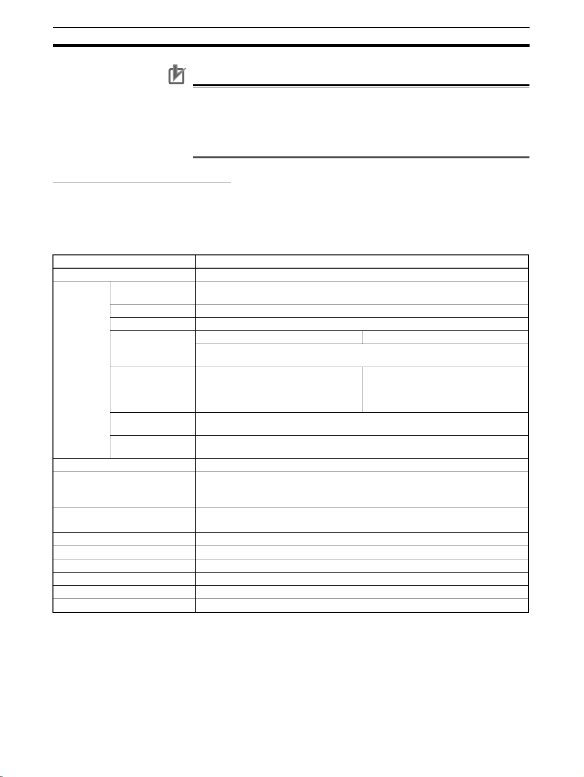
Option Units Section 2-3
Precautions for Correct Use
• Only CP1W-CIF41 Ethernet Option Boards with unit version 2.0 or later can
be used. If another Option Board is used, the G9SP-series Controller will
detect an Unsupported Option Board Error (the MS indicator will flash red).
• Always turn OFF the power supply to the G9SP-series Controller before
mounting or removing Option Boards.
Communications Specifications
Only the UDP/IP protocol can be used for Ethernet communications with the
G9SP-series Controller. Refer to SECTION 7 Communications with a Stan-
dard PLC Using an Option Board for the communications settings of the connected Standard PLC.
Ethernet Communications Specifications
Item Specifications
Type 100Base-TX (can be used as 10Base-T)
Transmis-
sion specifications
Current consumption 130 mA max. at 5 V DC
Vibration resistance Conforms to JIS 0040.
Shock resistance Conforms to JIS 0041.
Ambient operating temperature 0 to 55°C
Ambient humidity 10% to 90% (with no condensation)
Atmosphere Must be free of corrosive gas.
Ambient storage temperature -20 to 75°C
Weight 23 g max.
Dimensions 36.4×36.4×28.2 mm (W×H×D)
Media access
method
Modulation method Baseband
Transmission paths Star form
Baud rate 100 Mbit/s (100Base-TX) 10 Mbit/s (10Base-T)
Transmission media Unshielded twisted-pair (UTP) cable
Transmission distance
Number of cascade
connections
CSMA/CD
The internal baud rate between the G9SP-series Controller and Ethernet Option
Board is 115.2 kbps.
Unshielded twisted-pair (UTP) cable
Categories: 5, 5e
Shielded twisted-pair (STP) cable
Categories: 100 Ω at 5, 5e
100 m (distance between hub and node)
No restrictions in using switching hubs
10 to 57Hz: 0.075-mm amplitude, 57 to 150 Hz: acceleration 9.8 m/s
directions for 80 minutes each (sweep time: 8 minutes × 10 sweeps = 80 minutes)
147 m/s
2
, 3 times each in X, Y, and Z directions
Categories: 3, 4, 5, 5e
Shielded twisted-pair (STP) cable
Categories: 100 Ω at 3, 4, 5, 5e
2
in X, Y, and Z
Note Communications with OMRON PLCs can be performed using the FINS/UDP
protocol.
2-3-3 Memory Cassette (CP1W-ME05M)
Refer to SECTION 11 Backup and Restore Data Using Memory Cassette for
information on using a Memory Cassette with the G9SP-series Controller.
50
Page 77

Hardware Settings
Calculating Response Performance
This section describes the startup time and reaction time of the G9SP-series Controller.
3-1 Startup Time . . . . . . . . . . . . . . . . . . . . . . . . . . . . . . . . . . . . . . . . . . . . . . . . . . 52
3-2 Reaction Times . . . . . . . . . . . . . . . . . . . . . . . . . . . . . . . . . . . . . . . . . . . . . . . . 53
3-2-1 Reaction Time Concepts. . . . . . . . . . . . . . . . . . . . . . . . . . . . . . . . . . 53
3-2-2 Local Input and Local Output Reaction Times. . . . . . . . . . . . . . . . . 53
SECTION 3
51
Page 78

Startup Time Section 3-1
3-1 Startup Time
This section describes the operating flow and startup time of the G9SP-series
Controller.
Operation Flow
The following flowchart shows the operation cycle of the G9SP-series Controller.
Power ON
Initialization
System processing
Initialization Time
The G9SP-series Controller performs initialization when the power supply is
turned ON. During initialization, the G9SP-series Controller performs hardware self-diagnosis. The initialization takes up to 3 seconds to be completed
from the time that the power is turned ON.
Time Required to RUN Mode
The G9SP-series Controller will start operation in RUN Mode within 3 seconds after the power supply is turned ON when operation starts automatically.
A Standard PLC can monitor the Unit Normal Operating Flag to see if the
G9SP-series Controller has started normal operation. The G9SP-series Controller turns ON the Unit Normal Operating Flag when the following conditions
have been met.
Input refresh
Cycle time
(depends on
program)
User application processing
(logic operations)
Output refresh
USB/Option Board
communications processing
• RUN Mode has been entered.
• There are no errors in the G9SP-series Controller.
52
Page 79

Reaction Times Section 3-2
3-2 Reaction Times
This section describes how to calculate reaction times (safety response performance) for the G9SP-series Controller.
3-2-1 Reaction Time Concepts
Reaction Time
The reaction time is the time required to stop machine operation in a worstcase scenario considering the occurrence of faults and failures in the safety
chain. The safety chain is the logical connections that are required to achieve
a safety function, including the Safety Input device, G9SP-series Controller,
and Safety Output device. The reaction time is used to calculate the safety
distance.
3-2-2 Local Input and Local Output Reaction Times
This section describes the local Safety I/O reaction time for the G9SP-series
Controller. When calculating the reaction time of the overall safety chain, calculate separately the reaction times of safety sensor and switches, such as
light curtains, and actuators, such as safety relays.
Safety Sensor/
Switch
Sensor/Switch
reaction time
Elements for Calculating the Reaction Time
The reaction time for local Safety I/O on the G9SP-series Controller depends
on the following conditions. Check the conditions and values before calculating the reaction time.
■ Cycle Time
The cycle time depends on the size and contents of the program.
■ Input OFF Delay Time
If an OFF delay is set for an input, e.g., to prevent chattering, the OFF delay
time must be added to the reaction time.
Precautions for Correct Use
• If the cycle time changes as the result of changes to the program, calculate
the reaction time again.
• If an Off-Delay Timer function block is used in the program or if loop-back
connections are used, they must also be added to the reaction time.
G9SP-series
Safety Controller
Local input or
output reaction
time
Actuator
Actuator
reaction time
Checking the Safety Input Devices, Cycle Time, and Input OFF Delay Times
The cycle time and input OFF delay times can be checked on the configuration report that is output from the G9SP Configurator.
53
Page 80

Reaction Times Section 3-2
Reaction Time Formula
The formula for calculating reaction time for local Safety I/O on the G9SPseries Controller is given below.
Local Safety I/O reaction time = (Cycle time × 2) − 2 + Input OFF delay time [ms]
!WARNING Serious injury may possibly occur due to loss of required safety functions.
Confirm that the calculated reaction times meet the required specifications for
all safety chains.
Additional Information
The safety sensor/switch reaction times are given below for when the following OMRON Safety Sensors or Switches are connected directly to the G9SPseries Controller.
Connected device Safety Sensor/Switch
reaction time
E3ZS or E3FS Single Beam Safety
Sensor
D40A Non-contact
Switch
D40Z Non-contact
Switch
UM Safety Mat (Cycle time × 3) ms Cycle time = 4 ms
2 ms + (Cycle time × 3) ms Cycle time = 4 ms
2 ms + (Cycle time × 2) ms 5 ms ≤ Cycle time ≤ 9 ms
2 ms + (Cycle time × 1) ms 10 ms ≤ Cycle time
6 ms + 0.4 ms × Number of
connected Switches
Always 31 ms Cycle time ≤ 10 ms
(Cycle time × 3) ms 11 ms ≤ Cycle time
(Cycle time × 2) ms 5 ms ≤ Cycle time ≤ 8 ms
(Cycle time × 1) ms 9 ms ≤ Cycle time
---
Cycle time
The fault detection time for 24-V short-circuit faults on D40A non-contact door
switch input is (Cycle time × 3) ms max.
When calculating the safe distance for applications other than as door
switches, use a Safety Sensor/Switch reaction time of (Cycle time × 3) ms.
Safety Sensor/Switch reaction time calculation examples are provided in the
following table for each cycle time.
Connected device Sensor/Switch reaction time [ms]
Cycle time 45678910111215202530
E3ZS or E3FS Single
Beam Safety Sensor
D40A Non-contact
Switch
D40Z Non-contact
Switch
UM Safety Mat 12 10 12 14 16 9 10 11 12 15 20 25 30
14 12 14 16 18 20 12 13 14 17 22 27 32
6 + 0.4 × Number of connected Switches
(Independent of the cycle time.)
31 31 31 31 31 33 36 45 60 75 90
54
Page 81

Hardware Settings
Installation and Wiring
This section describes how to install and wire the G9SP-series Controller.
4-1 Installation. . . . . . . . . . . . . . . . . . . . . . . . . . . . . . . . . . . . . . . . . . . . . . . . . . . . 56
4-1-1 Installation Location . . . . . . . . . . . . . . . . . . . . . . . . . . . . . . . . . . . . . 56
4-1-2 Unit Arrangement . . . . . . . . . . . . . . . . . . . . . . . . . . . . . . . . . . . . . . . 58
4-1-3 Installation . . . . . . . . . . . . . . . . . . . . . . . . . . . . . . . . . . . . . . . . . . . . 59
4-1-4 Connecting Expansion I/O Units and Expansion Units . . . . . . . . . . 60
4-1-5 Mounting Option Boards . . . . . . . . . . . . . . . . . . . . . . . . . . . . . . . . . 62
4-2 Wiring . . . . . . . . . . . . . . . . . . . . . . . . . . . . . . . . . . . . . . . . . . . . . . . . . . . . . . . 63
4-2-1 Wire Sizes . . . . . . . . . . . . . . . . . . . . . . . . . . . . . . . . . . . . . . . . . . . . . 63
4-2-2 Wiring the Power Supply . . . . . . . . . . . . . . . . . . . . . . . . . . . . . . . . . 64
SECTION 4
55
Page 82

Installation Section 4-1
4-1 Installation
This section provides precautions on the environmental factors that must be
considered and the installation location of each G9SP-series Unit.
4-1-1 Installation Location
Installation Environment
Do not install the G9SP-series Controller in the following locations.
• Locations subject to ambient temperatures lower than 0°C or higher than
55°C.
• Locations subject to condensation as the result of severe changes in temperature.
• Locations subject to ambient humidity lower than 10% or higher than
90%.
• Locations subject to corrosive or flammable gases.
• Locations subject to excessive dust, salt, or metal filings.
• Locations subject to direct shock or vibration.
• Locations subject to direct sunlight.
• Locations subject to water, oil, or chemicals.
Always enclose or protect the G9SP-series Controller sufficiently in the following locations.
• Locations subject to static electricity or other forms of noise.
• Locations subject to strong electromagnetic fields.
• Locations subject to possible exposure to radioactivity.
• Locations close to power lines.
Installation in Control Panels
When the G9SP-series Controller is being installed in a control panel, be sure
to provide proper ambient conditions as well as access for operation and
maintenance.
Installation Orientation
When installing the G9SP-series Controller in a control panel, it must be
installed with the side with indicators and communications ports facing the
front to ensure proper heat dissipation.
56
Page 83

Installation Section 4-1
Accessibility for Operation and Maintenance
• To ensure safe access for operation and maintenance, separate the
G9SP-series Controller as much as possible from high-voltage equipment
and moving machinery.
• The G9SP-series Controller will be easiest to install and operate if it is
mounted at a height of 1.0 to 1.6 m above the floor.
!Caution Do not touch the power supply or the area around the I/O terminals while
power is being supplied or immediately after power has been turned OFF.
Doing so may result in burns.
Precautions for Correct Use
After the power supply has been turned OFF, wait until the G9SP-series Controller has sufficiently cooled before touching it.
Improving Noise Resistance
Leave space between the G9SP-series Controller and control panel or other
devices to allow adequate dissipation of heat generated by the power supply.
• Do not mount the G9SP-series Controller in a control panel containing
high-voltage equipment.
• Install the G9SP-series Controller at least 200 mm (6.5 feet) from power
lines.
Power Line
Temperature Control
200 mm min.
G9SP
200 mm min.
• Ground the mounting plate between the G9SP-series Controller and the
mounting surface.
The ambient operating temperature around the G9SP-series Controller must
be between 0 and 55°C. Observe the following precautions.
• Provide enough space for good air flow.
• Do not install the G9SP-series Controller above equipment that generates
a large amount of heat such as heaters, transformers, or high-capacity
resistors.
• If the ambient temperature exceeds 55°C, install a cooling fan or air conditioner.
57
Page 84

Installation Section 4-1
4-1-2 Unit Arrangement
This section describes how to arrange the G9SP-series Controller Units.
As shown in the following diagrams, Units can be arranged in one or two rows
when Expansion I/O Units or Expansion Units are used.
Arrangement in One Row
Expansion I/O Units and Expansion Units can be installed in a side-by-side
arrangement.
G9SP-series Controller
CP-series Expansion I/O Units
Arrangement in Two Rows
The Units can be arranged in two rows using the CP1W-CN811 I/O Connecting Cable (800 mm).
CP1W-CN811
I/O Connecting Cable
58
Precautions for Correct Use
I/O Connecting Cable can be used in one place only in each Controller. It cannot be used between Expansion I/O Units or in more than one place in the
same Controller.
Page 85

Installation Section 4-1
4-1-3 Installation
This section describes how to install the G9SP-series Controller.
Dimensions and Installation Height
Dimensions
85
A
B
90100110
Four, 4.5 dia.
Model number A B Weight
G9SP-N10S 86 76 290 g max.
G9SP-N10D 130 120 440 g max.
G9SP-N20S 130 120 430 g max.
81
8
Installation Height
Installation Methods
DIN Track Installation
Surface Installation
The installation height is approximately 90 mm.
When a Connecting Cable is connected to an Option Board, however, the
additional height must be included. Always allow for the additional height
when considering the depth of the control panel in which the G9SP-series
Controller is to be mounted.
There are two installation methods.
The Units can be mounted to PEP-50N (50 cm) or PEP-100N/100N2 (100
cm) DIN Tracks. Secure the DIN Track with screws in at least three places.
DIN Track
Secure with screws
Units can be directly mounted in the control panel using M4 screws.
59
Page 86

Installation Section 4-1
Mounting Brackets
DIN Track
Secure the DIN Track to the control panel using M4 screws at interval of
210 mm or less (6 holes or fewer). The tightening torque is 1.2 N·m.
End Plates
Mounting with Screws
PFP-100N2
4.5
25
15
10
PFP-100N/50N
4.5
25 25
15
10
25
1000
1000 (500)*
28-25 × 4.5 long holes
25
251025 15(5)*
15
25
10
*PFP-50N dimensions are given in parentheses.
30±0.3
27
7.3±0.15
35±0.3 27±0.15
16
24
29.2
1.51
1
Use the PFP-M End Plates to secure the Units so that they do not move
towards one end or the other of the DIN Track.
1. Open mounting holes in the mounting surface according to the dimensions
diagram.
2. Use M4 screws, which fit the holes on the G9SP-series Controller. The
tightening torque is 1.2 N·m.
4-1-4 Connecting Expansion I/O Units and Expansion Units
This section describes how to connect Expansion I/O Units and Expansion
Units.
Connection Methods
1,2,3... 1. Remove the cover from the G9SP-series Controller’s or the Expansion I/O
Unit’s expansion connector. Use a flat-head screwdriver to remove the cover from the Expansion I/O Connector.
Expansion Connector Cover
(1) Remove
60
Page 87

Installation Section 4-1
2. Insert the Expansion I/O Unit’s connecting cable into the G9SP-series
G9SP-series Controller’s or the Expansion I/O Unit’s expansion connector.
(2) Insert
3. Attach the cover to the G9SP-series Controller’s or the Expansion I/O
Unit’s expansion connector.
Precautions for Correct Use
• Always turn OFF the power supply to the G9SP-series Controller before
mounting or removing Expansion I/O Units.
• Separate the G9SP-series Controller from the Expansion I/O Units by about
10 mm.
Precautions on Connecting Units
The following restrictions apply to the Expansion I/O Units that can be connected to the G9SP-series Controller.
Applicable Models
Refer to 1-1-2 Basic System and Configuration Devices and 2-2 Expansion
I/O Units for information on the Expansion I/O Units that can be connected.
Maximum Number of Connectable Units
Up to two Expansion I/O Units can be connected.
Configuration Data Agreement
If the actual configuration does not agree with the configuration data, a nonfatal error will occur in the G9SP-series Controller. Correct the configuration
or the configuration data so that they agree. Refer to SECTION 13 Trouble-
shooting for information on errors.
(3) Attach
61
Page 88

Installation Section 4-1
4-1-5 Mounting Option Boards
This section describes how to mount an Option Board.
Mounting and Removal
Mounting
1,2,3... 1. Turn OFF the power supply to the G9SP-series Controller.
2. Remove the cover to the Option Board slot. If you squeeze the top and bottom lock levers on the cover together to release the lock, you can remove
the cover.
3. Make sure the Board is in the correct orientation and firmly press it into the
slot until it clicks into place.
Removal
Always turn OFF the power supply before removing an Option Board. If you
squeeze the top and bottom lock levers on the Option Board together to
release the lock, you can remove the Option Board.
Precautions for Correct Use
Always turn OFF the power supply to the G9SP-series Controller before
mounting or removing Option Boards.
Precautions When Connecting an Option Board
The following restrictions apply to the Option Boards that can be mounted to
the G9SP-series Controller.
Applicable Models
Refer to 1-1-2 Basic System and Configuration Devices for information on the
Expansion I/O Units that can be connected.
Maximum Number of Boards
Only one Option Board can be mounted.
62
Page 89
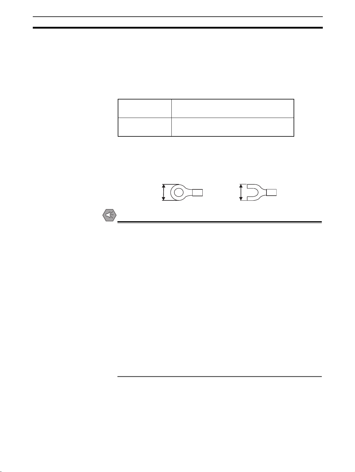
Wiring Section 4-2
4-2 Wiring
This section describes wiring methods for the G9SP-series Controller and
CP-series Expansion I/O Units.
4-2-1 Wire Sizes
Use the following wires to wire the power supply and external I/O devices to
the G9SP-series Controller.
Solid wire
Stranded wire
0.32 to 0.82 mm
0.32 to 0.5 mm
0.5 to 1.3 mm
0.5 to 0.82 mm
* When wiring two wires to one terminal, use two wires of the same type and
thickness.
• M3 self-rising terminals are used on the screw terminals. Tighten the terminal block screws to the torque of 0.5 N·m.
• Use crimp terminals (M3) having the dimensions shown below.
2
, AWG22 to AWG18
2
, AWG22 to AWG20*
2
, AWG20 to AWG16
2
, AWG20 to AWG18*
6.2 mm max.
6.2 mm max.
Precautions for Safe Use
• Disconnect the G9SP-series Controller from the power supply before starting wiring. Devices connected to the Controller may operate unexpectedly.
• Properly apply the specified voltage to the G9SP-series Controller power
supply and input terminals. Applying an inappropriate DC voltage or any AC
voltage may result in failure of specified functions, reduced safety functions,
damage to the product, and burning.
• Never apply a voltage that exceeds the input voltage for Input Units or the
maximum switching capacity for Output Units.
• When the power supply has positive and negative terminals, always wire
them correctly.
• Be sure to separate the communications cables and I/O cables from highvoltage/high-current lines.
• Do not bend a cable past its natural bending radius or pull in it with excessive force. Doing so will damage the cable.
• Be careful not to get your fingers caught when attaching terminal blocks to
the G9SP-series Controller.
• Incorrect wiring may lead to loss of safety functions. Wire conductors correctly and verify the operation of the G9SP-series Controller before using
the system in which the Controller is incorporated.
63
Page 90

Wiring Section 4-2
4-2-2 Wiring the Power Supply
Wiring the Power Supply
The G9SP-series Controller provides power terminals V1/G1 for the internal
and input circuits and power terminals V2/G2 for the output circuits.
Use a power supply with a voltage fluctuation range of 20.4 to 26.4 VDC.
• If the voltage may drop due to the starting current or inrush current for
output devices, use different power sources for the two power supplies.
• When using more than one G9SP-series Controller, use separate power
supply circuits for each G9SP-series Controller to prevent the malfunction
of breakers and voltage drops from inrush current.
24 VDC
USB
D+
D−
Internal Circuit
Safety
Input
Circuit
Tes t
Output
Circuit
Safety
Output
Circuit
Standard
Output
Circuit
V1
G1
Si0
Si19
T0
T5
V2
G2
So0
So7
O0
O3
L
L
L
L
Power Supply Selection
Power Supply Grounding
Use a DC power supply satisfying the following requirements.
• The secondary circuit of the DC power supply must be isolated from the
primary circuit by double insulation or reinforced insulation.
• An isolated power supply that is limited to a current of 8 A or lower must
be used.
• The output hold time must be 20 ms or longer.
• The DC power supply must be a SELV power supply that satisfies the
requirements of IEC/EN 60950-1 and EN 50178.
• Ground the 0-V side of the power supply terminals (G1 and G2) to enable
detecting faults for disconnected I/O wiring or ground faults.
• Ground to 100 Ω or less to provide stronger noise immunity.
• Do not share ground lines with other equipment or ground to structural
parts of buildings to prevent adverse influences.
Precautions for Safe Use
• Connect the positive and negative terminals correctly.
• Supply power to all of the Power Supply Units from the same source.
64
Page 91

Wiring Section 4-2
Precautions for Correct Use
• Wiring clippings can scatter when wiring. Leave the label attached to the
top of the Unit when wiring to prevent the entry of foreign matter.
• Remove the label after the completion of wiring to ensure proper heat dissipation.
65
Page 92

Wiring Section 4-2
66
Page 93

Software Design
SECTION 5
Preparations for Using the G9SP Configurator
This section describes the features and provides the installation procedure for the G9SP Configurator. The G9SP
Configurator is a software application that is used to program and debug a G9SP-series Controller.
5-1 Overview. . . . . . . . . . . . . . . . . . . . . . . . . . . . . . . . . . . . . . . . . . . . . . . . . . . . . 68
5-1-1 System Requirements and System Configuration . . . . . . . . . . . . . . 68
5-1-2 G9SP Configurator Functions. . . . . . . . . . . . . . . . . . . . . . . . . . . . . . 69
5-2 Installation. . . . . . . . . . . . . . . . . . . . . . . . . . . . . . . . . . . . . . . . . . . . . . . . . . . . 70
5-2-1 Installing the G9SP Configurator . . . . . . . . . . . . . . . . . . . . . . . . . . . 70
5-2-2 Installing the USB Driver . . . . . . . . . . . . . . . . . . . . . . . . . . . . . . . . . 70
67
Page 94
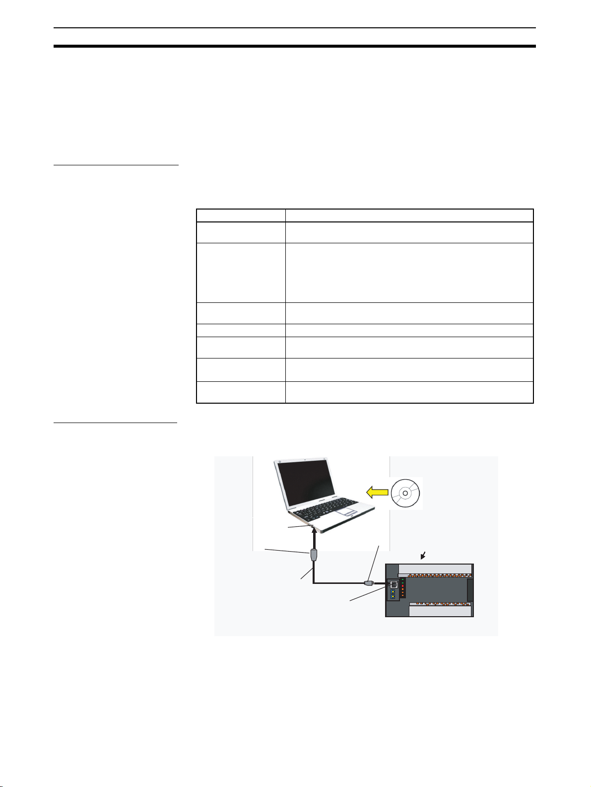
Overview Section 5-1
5-1 Overview
The G9SP Configurator is a software application that is used to initialize, program, monitor, and debug G9SP-series Controller. This section describes the
features of the G9SP Configurator and its system requirements.
5-1-1 System Requirements and System Configuration
System Requirements
The following system is required to operate the G9SP Configurator. Make
sure your system provides the following conditions and has the necessary
components.
Item Description
CD-ROM or DVDROM drive
Supported operating
systems
CPU A computer with a processor recommended by Microsoft Corpo-
RAM The memory capacity recommended by Microsoft Corporation.
Required hard disk
space
Display High-brightness display of 800 x 600 SVGA min.
Connection port to
Controller
One or more
Windows XP SP3 (32-bit edition), Windows Vista SP2 (32-bit edition or 64-bit edition), Windows 7 (32-bit edition or 64-bit edition),
Windows 8 (32-bit edition or 64-bit edition), Windows 8.1 (32-bit
edition or 64-bit edition), or Windows 10 (32-bit edition or 64-bit
edition)
Note Administrator rights are required for installation.
ration.
200 MB min.
256 colors min.
USB port
System Configuration
The G9SP Configurator is installed on a computer and connected to the
G9SP-series Controller with a commercially available USB cable.
G9SP Configurator
USB port
Type-A connector
Type-B connector
Commercially
available USB cable*1
Peripheral USB port
(USB 1.1, B-type connector)
*1: The USB cable must be 3 m or shorter.
G9SP-series Controller
68
Page 95

Overview Section 5-1
Precautions for Correct Use
• The G9SP Configurator cannot be used if it is connected to an RS-232C
Option Board or Ethernet Option Board. Always connect it directly to the
USB port.
• Do not turn OFF the power supply to the G9SP-series Controller or disconnect the USB cable while online. Before removing the USB cable, place the
application offline.
• The computer cannot be placed on standby while it is connected to the
G9SP-seried Controller with a USB cable.
5-1-2 G9SP Configurator Functions
The G9SP Configurator can be used for the following purposes.
G9SP Configurator
Setup and Programming
Hardware Settings
The hardware configuration and Safety I/O terminals of the G9SP-series
Controller are set here.
System Settings
The cycle time and other software functions of the G9SP-series
Controller are set here.
Programming
Safety-certified function blocks
are used to program the
G9SP-series Controller.
Offline Simulation
The program can be debugged on the computer.
Search Functionality
You can search for I/O tags and error locations in the program.
Force-set/reset
The actual I/O of the G9SP-series Controller can be turned ON and OFF.
Online Monitoring
The program execution status, error log, and other items in the G9SP-series
Controller can be monitored.
Unit Configuration
Safety Output
Terminal Settings
Logic Editor
User-defined Function Blocks
Debugging and Maintenance
Displaying and
Printing Reports
Settings can be checked and printed.
Access Rights
Protections can be set using passwords for changes to settings in the G9SP-series
Controller and to accessing and editing project files on the computer.
Other Functions
69
Page 96

Installation Section 5-2
5-2 Installation
This section describes the installation procedure that must be performed to
use the G9SP Configurator.
Precautions for Correct Use
To install the software, log on as a user that meets the following conditions.
• Administrator privileges
• Only single-byte alphanumeric characters in the user's account name (version 1.00 only)
5-2-1 Installing the G9SP Configurator
Preparing for Installation
Check the following items before beginning with the installation.
Available Hard Disk Space
The G9SP Configurator can be installed on the hard disk only. At least 200
MB of hard disk space is required. Make sure that there is enough space
available.
Windows Environment and Installation Destination
The G9SP Configurator is a software application for a Windows operating
environment. The software is installed on Windows. Make sure that Windows
is installed and functioning correctly on the computer.
Installation Procedure
This section describes how to install the software on a computer using the following drive configuration as an example.
C drive: Hard disk drive
D drive: CD-ROM drive
1,2,3... 1. Start Windows and insert the G9SP Configurator Master Disk in the CD-
ROM drive. The installation program will be started by the computer’s autorun function. If the installation program does not start, select Specify File
Name and Run from the Windows Start Menu, enter “d:\setup” and click
the OK Button.
2. Complete the installation process following the instructions provided on-
screen.
Uninstalling the G9SP Configurator
Uninstall the G9SP Configurator when it is no longer required. Uninstall the
application using Add and Remove Applications in the control panel.
5-2-2 Installing the USB Driver
70
The USB driver for the G9SP-series Controller must be installed on the computer running the G9SP Configurator in order to connect the G9SP-series
Controller to the computer via USB. The USB driver is stored in the following
directory in the computer when the G9SP Configurator is installed.
\Drivers\USB in the installation folder
Page 97

Installation Section 5-2
Windows XP
The procedure to install the driver on a Windows XP computer is given in this
section.
1,2,3...
1. Turn ON the power supply to the G9SP-series Controller and connect the
USB port on the G9SP-series Controller to a USB port on the computer
using a USB cable.
The computer will automatically detect the G9SP-series Controller when
the cable is connected and display a message saying that new hardware
has been detected. The Add Hardware Wizard will also be displayed.
2. In the Found New Hardware
Wizard Dialog Box, select
the No, not this time option
and click the Next Button.
3. Select the Install from a list
or specific location (Advanced) Option and click the
Next Button.
4. Select the Search the best
driver in these locations
Check Box and select only
the Include this location in
the search Option. Specify
the directory where the USB
driver was saved (given previously) as the location to
search and click the Next
Button.
71
Page 98
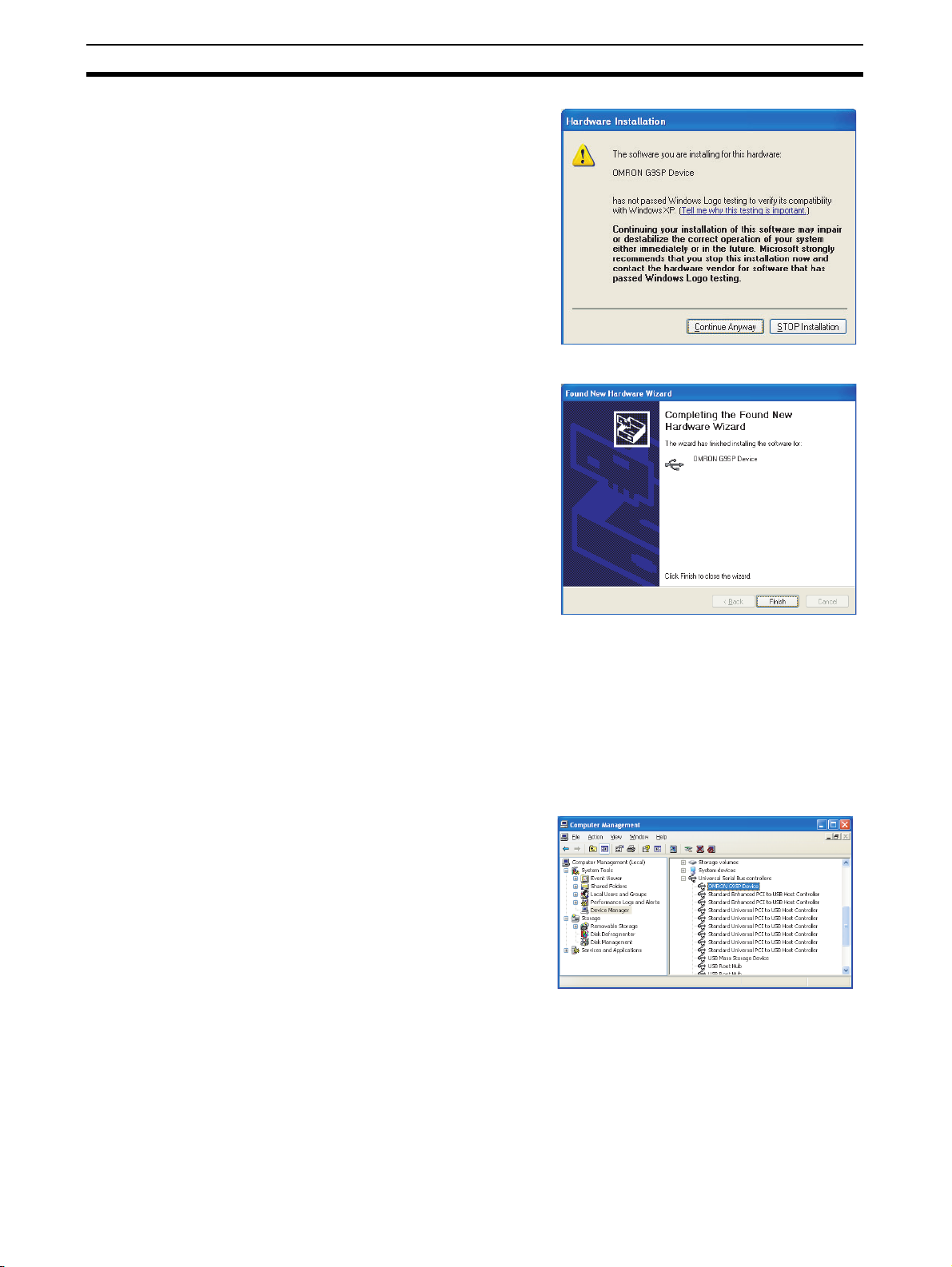
Installation Section 5-2
5. If a warning message appears saying that the driver
has not passed the Windows
logo test, ignore it and click
the Continue Anyway Button.
6. The driver will be installed.
7. This dialog box will be displayed if the installation is
completed normally. Click
the Finish Button.
Confirmation
1,2,3...
When Installation Fails
1,2,3... 1. Open the Computer Management Window on the computer and select the
This completes installation of the USB driver for the G9SP Configurator.
Check that the driver has been installed correctly after the installation.
1. From the desktop click Start, right-click My Computer, and select Man-
age. The Computer Management Window will be displayed.
2. Select the Device Manager on the navigation pane.
3. If the OMRON G9SP Device
is displayed in the list of the
universal serial bus controllers, then the USB driver has
been installed correctly.
Device Manager on the navigation pane. If OMRON-PLC is displayed as a
universal serial bus controller, installation of the USB driver has failed.
2. Right-click on OMRON-PLC and select Delete to delete the driver. Reinsert the USB cable to display the USB driver installation dialog box. Perform the re-installation procedure to install the driver.
72
Page 99

Installation Section 5-2
Windows Vista
The procedure to install the driver on a Windows Vista computer is given in
this section.
1,2,3...
1. Turn ON the power supply to the G9SP-series Controller and connect the
USB port on the G9SP-series Controller to a USB port on the computer
using a USB cable.
The Add Hardware Wizard will also be displayed.
2. Select the Locate and install
driver software Option.
3. Click the Don’t search online
Option in the Found New
Hardware Dialog Box.
4. Select the following: I don’t
have the disc. Show me other options.
73
Page 100

Installation Section 5-2
5. Select the Browse my computer for driver software (advanced) Option.
6. Click the Browse Button,
specify the directory where
the USB driver was saved
(given previously) as the location to search and click the
Next Button.
Confirmation
7. The Windows Security Dialog Box will be displayed.
Click the Install Button.
8. The driver will be installed.
9. When the driver installation
is completed normally, the
installation completed dialog
box will be displayed. Click
the Close Button.
This completes installation of the USB driver for the G9SP Configurator.
Check that the driver has been installed correctly after the installation.
74
1,2,3...
1. From the desktop click Start, right-click Computer, and select Manage.
The Computer Management Window will be displayed.
 Loading...