

Page 1

HOST CONNECTION
M ANUAL
Cat. No. Z924-E1-01
G9SP Series
Safety Controller
Page 2

OMRON, 2010
All rights reserved. No part of this publication may be reproduced, stored in a retrieval system, or transmitted, in any form, o
r
by any means, mechanical, electronic, photocopying, recording, or otherwise, without the prior written permission o
f
OMRON.
No patent liability is assumed with respect to the use of the information contained herein. Moreover, because OMRON is constantly striving to improve its high-quality products, the information contained in this manual is subject to change without
notice. Every precaution has been taken in the preparation of this manual. Nevertheless, OMRON assumes no responsibility
for errors or omissions. Neither is any liability assumed for damages resulting from the use of the information contained in
this publication.
Page 3

1
Introduction
Thank you for purchasing a G9SP-series Safety Controller. This manual contains information
required to use the G9SP-series Controller. Please thoroughly read and understand this manual
before you use the G9SP-series Controller.
Intended Audience
This manual is intended for the following personnel, who must also have knowledge of electrical
systems (an electrical engineer or the equivalent).
- Personnel in charge of installing FA systems.
- Personnel in charge of designing FA systems.
- Personnel in charge of managing FA systems and facilities.
- Personnel in charge of qualifications and authority in all phases, including system design,
installation, operation, maintenance, and disposal.
Page 4

2
Manual Configuration
Information on the operation of G9SP-series Safety Controllers is provided in the following
manuals. Refer to the specific manual depending on the information that is required.
Manula name Contents Cat. No.
G9SP-series Safety Controller
Host Connection Manual (this
manual)
This manual provides sample ladder
programming and describes how to
connect to a Standard PLC from another
manufacturer using the communications
functionality of the G9SP-series Controller's
Option Board. The procedure for connecting to a
Standard PLC from another manufacturer is
described in the G9SP Operation Manual.
Z924
G9SP-series Safety Controller
Operation Manual
This manual provides detailed specifications and
describes functions and application methods for
the G9SP-series Controller in detail.
Z922
G9SP-series Safety Controller
Instructions Reference Manual
This manual describes the safety programming
methods, provides the specifications, and
describes the functions and operating methods
of the G9SP-series Controllers.
Z923
Page 5

3
Table of Contents
Introduction ....................................................................................................................1
Manual Configuration.....................................................................................................2
Table of Contents
...........................................................................................................3
Section 1Connecting to OMRON PLCs
1 - 1 Functionality ..................................................................................................1-2
1 - 2 RS-232C Serial Communications..................................................................1-3
1 - 3 Ethernet Communications .............................................................................1-4
Section 2Connecting to Mitsubishi Electric PLCs
2 - 1 Functionality ..................................................................................................2-2
2 - 2 RS-232C Serial Communications..................................................................2-3
2 - 2 - 1 Communication Format..............................................................2-3
2 - 2 - 2 Application Example 1(Connecting to the Mitsubishi Standard PLC
Q Series)....................................................................................2-3
2 - 2 - 3 Application Example 2(Connecting to the Mitsubishi Standard PLC
FX Series)................................................................................2-10
2 - 3 Ethernet Communications ...........................................................................2-16
2 - 3 - 1 Communication Format............................................................2-16
2 - 3 - 2 Application Example ..............................................................2-16
Section 3Connecting to Siemens PLCs
3 - 1 Functionality ..................................................................................................3-2
3 - 2 RS-232C Serial Communications..................................................................3-3
3 - 2 - 1 Communication Format..............................................................3-3
3 - 2 - 2 Application Example ................................................................3-3
3 - 3 Ethernet Communications ...........................................................................3-11
3 - 3 - 1 Communication Format............................................................3-11
3 - 3 - 2 Application Example ..............................................................3-11
Page 6

Page 7

This section describes how to perform communications with OMRON standard
PLC through an RS-232C Option Board or Ethernet Option Board.
1 - 1 Functionality.................................................................................................. 1-2
1 - 2 RS-232C Serial Communications................................................................. 1-3
1 - 3 Ethernet Communications
............................................................................. 1-4
Connecting to OMRON PLCs
Page 8

1-2
1 - 1 Functionality
Refer to Section 7 Communications with a Standard PLC Using an Option Board of the
G9SP Series Safety Controller Operation Manual (Cat. No. Z922).
Page 9

1 - 2 RS-232C Serial Communications
1-3
1
Connecting to OMRON PLCs
1 - 2 RS-232C Serial Communications
Refer to Section 7 Communications with a Standard PLC Using an Option Board of the
G9SP Series Safety Controller Operation Manual (Cat. No. Z922).
Page 10

1-4
1 - 3 Ethernet Communications
Refer to Section 7 Communications with a Standard PLC Using an Option Board of the
G9SP Series Safety Controller Operation Manual (Cat. No. Z922).
Page 11

This section describes how to perform communications with Mitsubishi Electric
Standard PLC through an RS-232C Option Board or Ethernet Option Board.
2 - 1 Functionality.................................................................................................. 2-2
2 - 2 RS-232C Serial Communications................................................................. 2-3
2 - 2 - 1 Communications Format ..................................................................2-3
2 - 2 - 2
Application Example 1(Connecting to the Mitsubishi Standard PLC Q
Series.) .............................................................................................2-3
2 - 2 - 3
Application Example 2(Connecting to the Mitsubishi Standard PLC FX
Series.) ...........................................................................................2-10
2 - 3 Ethernet Communications............................................................................2-16
2 - 3 - 1 Communications Format ................................................................2-16
2 - 3 - 2
Application Example.......................................................................2-16
Connecting to Mitsubishi Electric PLCs
Page 12

2-2
2 - 1 Functionality
Refer to Section 7 Communications with a Standard PLC Using an Option Board of
the G9SP Series Safety Controller Operation Manual (Cat. No. Z922).
Page 13

2 - 2 RS-232C Serial Communications
2-3
2
Connecting to Mitsubishi Electric PLCs
2 - 2 RS-232C Serial Communications
This section provides a description and example of connection to a Mitsubishi
Electric Standard PLC. The No-protocol communications are available for
connection with a Mitsubishi Electric Standard PLC.
2 - 2 - 1 Communications Format
Refer to Section 7 Communications with a Standard PLC Using an Option Board of
the G9SP Series Safety Controller Operation Manual (Cat. No. Z922).
2 - 2 - 2 Application Example 1(Connecting to the Mitsubishi Standard
PLC Q Series.)
System Configuration
This section uses the following example to describe how to access the
G9SP-series Controller by performing serial communications through a
RS-232C Serial Comm- unications Board (CP1W-CIF01) from a Mitsubishi
Electric Standard PLC Q series.
MELSEC-Q
series
Serial
Communication
Module
G9SP-series
No-protocol
Mitsubishi Standard PLC(See Note.)
CP1W
-
CIF01
Option Board
Note:
This example uses the following Mitsubishi Electric Standard PLC.
Product Model/version
CPU Unit (Standard PLC) Q02HCPU
Serial Communication Module
QJ71C24N-R2
Support Software (for setup and creating ladder
programs)
GX Developer Version 8.90U
GX Configurator-SC Version2.21X
G9SP-series Controller Settings
Settings are not required. Make the communications settings in the Mitsubishi
Electric Standard PLC to match the serial communications specifications of the
G9SP-series Controller.
Page 14
2-4
Mitsubishi Electric PLC Q series Settings
Set serial communication module CH2 as given below in the PLC parameter using
the GX Developer and CH2 No-protocol system setting using the intelligent
function utility.
z PLC parameter settings
Set serial communication module CH2 as given below in the PLC parameter by
selecting[Project data list]-[Parameter]-[PLC parameter]-[I/O assignment].
Parameter Description Set value for this example
Communication protocol setting Communication protocol Non-procedure
Transmission setting Transmission setting Data bit :8bits
Parity bit :Yes
Odd/even parity:Even
Stop bit :1bit
Sum check code :No
Communication rate setting Baud rate 9600bps
z Intelligent function utility settings
Set serial communication module CH2 as given below in the CH2 Non procedure
system setting by selecting [Tools]-[Intelligent function utility]-[Start].
Parameter Description Set value for this example
Received data count designation Received data count 00C7(199bytes)
Receive complete code designation Receive complete code FFFF(Not desig nated)
Page 15
2 - 2 RS-232C Serial Communications
2-5
2
Connecting to Mitsubishi Electric PLCs
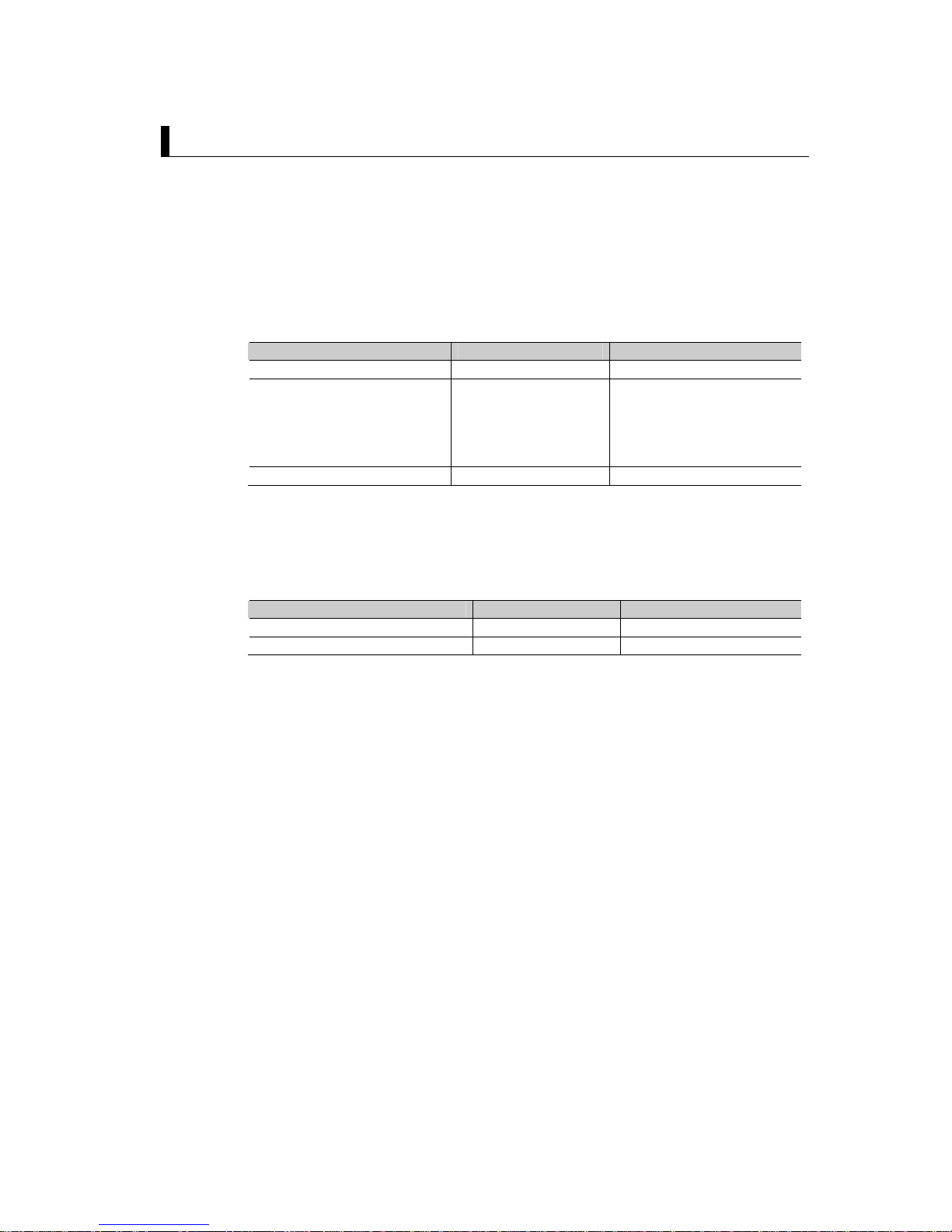
Communications cable
The suited cable is different according to the combination of component. Please
produce the cable of the following connecting wires when connecting with a
Mitsubishi Electric Standard PLC Q series (QJ71C24N-R2).
G9SP-series
RS-232C Serial Communications
Board
Mitsubishi Electric Q series
serial communication module
Connector Signal Pin No.
Pin No. Signal Connector
FG 1 1 CD
SD 2 2 RD
RD 3 3 SD
RS 4 4 ER
CS 5 5 SG
5V 6 6 DR
DR 7 7 RS
ER 8 8 CS
D-Sub
male
9-pin
SG 9 9 RI
D-Sub
male
9-pin
Sample Ladder Programming for Mitsubishi Electric PLC Q series
This section provides an example of programming to monitor Safety Input terminal
data of a G9SP-series Controller from a Mitsubishi Electric Standard PLC Q
series.
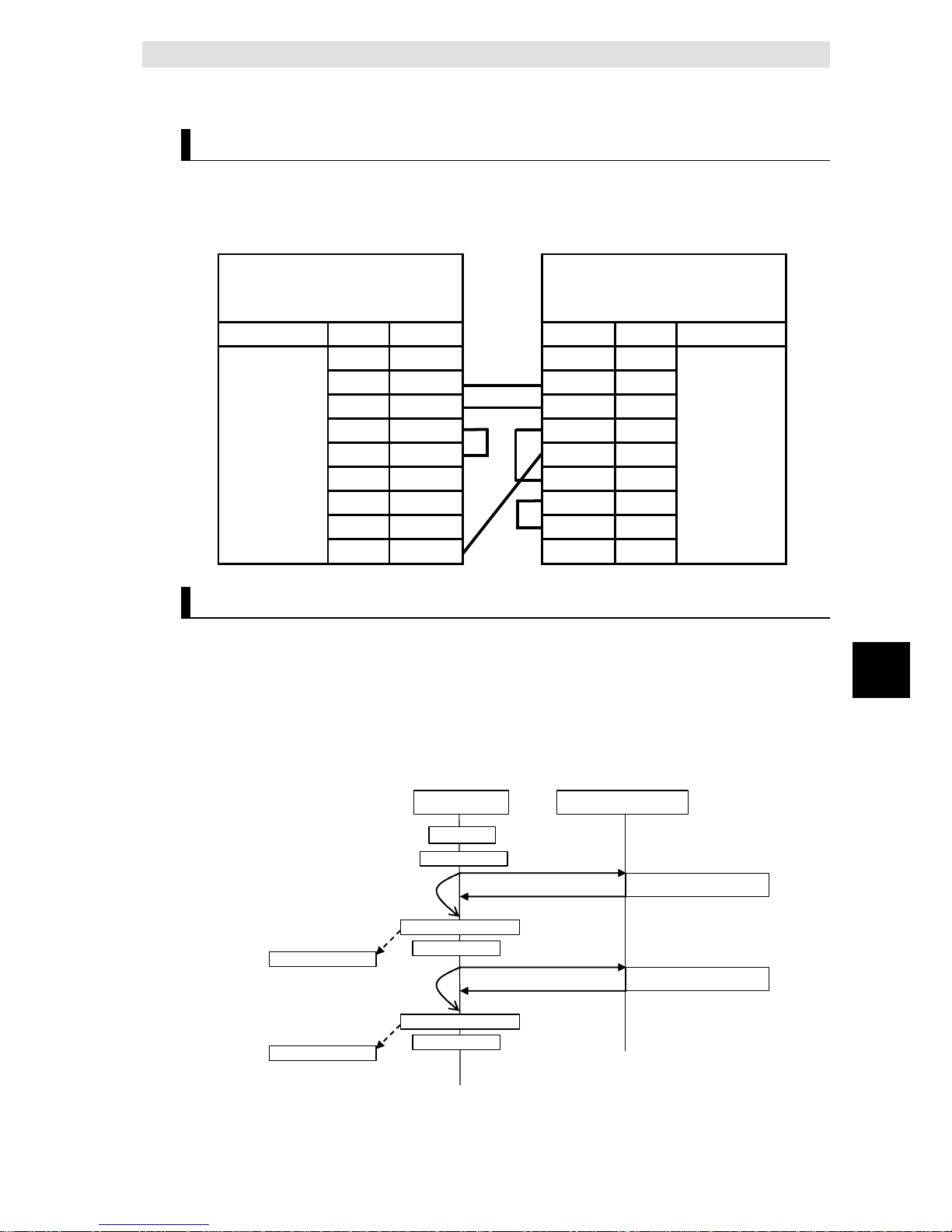
z RS-232C Serial Communications Sequence
The G9SP-series Controller returns a response to the command sent from the
Standard PLC.
Standard PLC G9SP-series Controller
Send processing
Initialization
Send/receive processing
Send/receive processing
Sent command
Reception response
Sent command
Reception response
Receive processing
Send processing
Receive processing
Send processing
Receive processing
after 300 ms
Receive processing
after 300 ms
Receive End
Receive End
Page 16
2-6
z Mitsubishi Electric Standard PLC Q series Memory Allocations
Start address End address Contents Description
D11 D20 RS-232C send command Data sent by the Standard PLC to the
G9SP-series Controller
D110 D209 RS-232C reception response Data received by the Standard PLC from
the G9SP-series Controller
D330 D351 Checksum calculation work area Work area for RS-232 C communications.
Used to calculate the check-sum
X100 X11F G9SP communications reception data
(written to G9SP-series Controller)
Data written to G9SP-series Controller from
Standard PLC. Stored in the communications reception data of the G9SP-series
Controller.
Y200 Y21F G9SP communications transmission data
(read from the G9SP-series Controller)
Communications data sent from the G9SPseries Controller is read.
Y220 Y24F G9SP Safety Input terminal data (read
from the G9SP-series Controller)
Safety Input terminal data of the G9SPseries Controller is read.
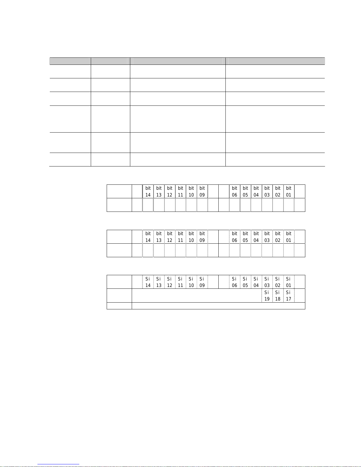
- G9SP Communications Reception Data
15 8 7 0
X100 bit
15
bit
14
bit13bit12bit11bit10bit09bit08bit07bit06bit05bit
04
bit
03
bit
02
bit01bit
00
X110 bit
31
bit
30
bit29bit28bit27bit26bit25bit24bit23bit22bit21bit
20
bit
19
bit
18
bit17bit
16
- G9SP Communications Transmission Data
15 8 7 0
Y200 bit
15
bit
14
bit13bit12bit11bit10bit09bit08bit07bit06bit05bit
04
bit
03
bit
02
bit01bit
00
Y210 bit
31
bit
30
bit29bit28bit27bit26bit25bit24bit23bit22bit21bit
20
bit
19
bit
18
bit17bit
16
- G9SP Safety Input Terminal Data
15 8 7 0
Y220 Si
15
Si
14 Si13Si12Si11Si10Si09Si08Si07Si06Si05
Si
04
Si
03
Si
02 Si01Si00
Y230 Reserved Si
19
Si
18 Si17Si16
Y240 Reserved
Page 17

2 - 2 RS-232C Serial Communications
2-7
2
Connecting to Mitsubishi Electric PLCs
z Sample Ladder Programming
- From Initial Settings to Cyclic Send/Receive
Initial Settings
Reception processing
Send processing
(1)
(2)
(3)
(4)
(5)
(6)
(7)
(8)
Page 18

2-8
- Reception completion processing
Reception complet io n pro ce ss i n g
(9)
(10)
Page 19

2 - 2 RS-232C Serial Communications
2-9
2
Connecting to Mitsubishi Electric PLCs
- Checksum Calculation Subroutine
Step Description
(1) The fixed portion of the send command is set. This processing is performed once at
startup.
(2) A communications refresh timer of 300 ms is started. This performs the first sending after
300 ms.
(3) Once 300 ms has elapsed, the RS-232C reception end bit (X0A) is checked, and receive
processing is performed if data has been received. A send command from the Standard
PLC is initially required, and so reception processing is performed after completing the
first send.
(4) To store the reception response in D100, the INPUT instruction is executed.
(5) G9SP communications reception data is set to the send command from X 100 and echo
back bit.
(6) The send command is transferred to the RS-232C send port, which enables sending to
the G9SP-series Controller.
(7) The checksum and the end code are set to the transmission command.The send
command is transferred to the RS-232C send port, which enables sending to the
G9SP-series Controller.
(8) The timer is restarted and the next receive processing is performed after 300 ms.
(9) The checksum calculation subroutine given above is called, and the checksum of the
reception response is calculated.
(10) The checksum of the reception response and the end code are checked, and the G9SP
Communications Transmission Data is copied to Y 200 and G9SP Safety Input Terminal
Data is copied to Y 220.
Page 20

2-10
2 - 2 - 3 Application Example 2(Connecting to the Mitsubishi Standard
PLC FX Series.)
System Configuration
This section uses the following example to describe how to access a G9SP-series
Controller by performing serial communications through a RS-232C Serial
Communications Board (CP1W-CIF01) from a Siemens Standard PLC FX series.
MELSEC-FX
series
Communi
cation
Adapter
G9SP-series
Non procedure
Mitsubishi Standard PLC(See Note.)
CP1W
-
CIF01
Option Board
Note:
This example uses the following Mitsubishi Electric Standard PLC.
Product Model/Version
CPU Unit (Standard PLC) FX3UC-32MT-LT
RS-232C Communication Adapter FX3U-232AP
Support Software (for setup and creating ladder
programs)
GX Developer Version 8.90U
G9SP-series Controller Settings
Settings are not required. Make the communications settings in the Mitsubishi
Electric Standard PLC to match the serial communications specifications of the
G9SP-series Controller.
Mitsubishi Electric PLC FX series Settings
Set RS-232C communication adapter CH1 as given below in the PLC parameter
using the GX Developer.
z PLC parameter settings
Set RS-232C communication adapter CH2 as given below in the PLC parameter
by selecting[Project data list]-[Parameter]-[PLC parameter]-[PLC System(2)].
Parameter Description Set value for this
example
Protocol Communication protocol Non-procedural
Data length 8bit
Parity Even
Stop bit
Transmission setting
1bit
Transmission Speed Baud rate 9600
Header Set the header. Yes
H/W Type Normally choose RS-232 or
RS-485.
Regular/RS232C
Transmission control
procedure
Choose format 1/format 4. Form1(without
CR,LF)
Time out judge time Set the time-out period. 30(300msec)
Page 21

2 - 2 RS-232C Serial Communications
2-11
2
Connecting to Mitsubishi Electric PLCs
Communications cable
The suited cable is different according to the combination of component. Please
produce the cable of the following connecting wires when connecting with a
Mitsubishi Electric Standard PLC FX series.
G9SP-series
RS-232C Serial Communications
Board
Mitsubishi Electric FX series
RS-232 communication adapter
Connector Signal Pin No.
Pin No. Signal Connector
FG 1 1 CD
SD 2 2 RD
RD 3 3 SD
RS 4 4 ER
CS 5 5 SG
5V 6 6 DR
DR 7 7
ER 8 8
D-Sub
male
9-pin
SG 9 9
D-Sub
male
9-pin
Page 22

2-12
Sample Ladder Programming for Mitsubishi Electric PLC FX series
This section provides an example of programming to monitor Safety Input terminal
data of a G9SP-series Controller from a Mitsubishi Electric Standard PLC FX
series.
z RS-232C Serial Communications Sequence
The G9SP-series Controller returns a response to the command sent from the
tandard PLC.
Standard PLC
G9SP-series Controller
Sent command
Reception response
Receive processing
after 300 ms
Send/Receive processing
Initialization
Send processing
Receive processing
Send processing
Sent command
Reception response
Send/Receive processing
Receive processing
Send processing
Receive processing
after 300 ms
z Mitsubishi Electric Standard PLC FX series Memory Allocations
Start address End address Contents Description
D100 D108 RS-232C send command Data sent by the Standard PLC to the
G9SP-series Controller
D200 D298 RS-232C reception response Data received by the Standard PLC from
the G9SP-series Controller
D330 D336 Checksum calculation work area Work area for RS-232C communications.
Used to calculate the check-sum
X100 X11F G9SP communications reception data
(written to G9SP-series Controller)
Data written to G9SP-series Controller from
Standard PLC. Stored in the communications reception data of the G9SP-series
Controller.
Y200 Y21F G9SP communications transmission
data (read from the G9SP-series Controller)
Communications data sent from the G9SPseries Controller is read.
Y220 Y24F G9SP Safety Input terminal data (read
from the G9SP-series Controller)
Safety Input terminal data of the G9SPseries Controller is read.
Page 23

2 - 2 RS-232C Serial Communications
2-13
2
Connecting to Mitsubishi Electric PLCs
- G9SP Communications Reception Data
15 8 7 0
X100 bit
15
bit14bit13bit12bit11bit10bit09bit08bit07bit06bit
05
bit
04
bit
03
bit02bit01bit
00
X110 bit
31
bit30bit29bit28bit27bit26bit25bit24bit23bit22bit
21
bit
20
bit
19
bit18bit17bit
16
- G9SP Communications Transmission Data
15 8 7 0
Y200 bit
15
bit14bit13bit12bit11bit10bit09bit08bit07bit06bit
05
bit
04
bit
03
bit02bit01bit
00
Y210 bit
31
bit30bit29bit28bit27bit26bit25bit24bit23bit22bit
21
bit
20
bit
19
bit18bit17bit
16
- G9SP Safety Input Terminal Data
15 8 7 0
Y220 Si
15 Si14Si13Si12Si11Si10Si09Si08Si07Si06
Si
05
Si
04
Si
03
Si 02Si01Si
00
Y230 Reserved Si
19
Si 18Si17Si
16
Y240 Reserved
z Sample Ladder Programming
- From Initial Settings to Cyclic Send/Receive
Initial Settings
(1)
Page 24

2-14
(6)
(2)
(3)
(4)
(5)
(7)
(8)
(9)
(10)
(11)
Reception processing
Send processing
Page 25

2 - 2 RS-232C Serial Communications
2-15
2
Connecting to Mitsubishi Electric PLCs
- Checksum Calculation Subroutine
Step Description
(1) The fixed portion of the send command is set. This processing is performed once at startup.
(2) A communications refresh timer of 300 ms is started. This performs the first sending after
300 ms.
(3) To execute the sending and receiving of the RS232C port, the RS instruction is executed.
(4) Once 300 ms has elapsed, to execute the transmission processing, the pulse is set to M0.
(5) Once 300 ms has elapsed, the RS-232C reception end bit (M8123) is checked, and receive
processing is performed if data has been received. A send command from the Standard
PLC is initially required, and so reception processing is performed after completing the first
send.
(6) The checksum calculation subroutine given above is called, and the checksum of the
reception response is calculated.
(7) The checksum of the reception response and the end code are checked, and the G9SP
Communications Transmission Data is copied to Y200 and G9SP Safety Input Terminal
Data is copied to Y220.
(8) G9SP communications reception data is set to the send command from X 100.
(9) The checksum calculation subroutine given above is called, and the checksum of the
transmission command is calculated.
(10) The checksum are set to the transmission command.The send command is transferred to
the RS-232C send port, which enables sending to the G9SP-series Controller.
(11) The timer is restarted and the next receive processing is performed after 300 ms.
Page 26

2-16
2 - 3 Ethernet Communications
This section provides a description and example of connection to a Mitsubishi
Electric Standard PLC. The FINS/UDP Protocol are available for connection with a
Mitsubishi Electric Standard PLC.
2 - 3 - 1 Communications Format
Refer to Section 7 Communications with a Standard PLC Using an Option Board of
the G9SP Series Safety Controller Operation Manual (Cat. No. Z922).
2 - 3 - 2 Application Example
System Configuration
This section uses the following example to describe how to access the
G9SP-series Controller by performing Ethernet communications through a
Ethernet Communica- tions Board (CP1W-CIF41) from a Mitsubishi Electric
Standard PLC Q series.
Q002
Ethernet
Interface
Unit
G9SP Series
FINS/UDP
Mitsubishi Standard PLC(See Note.)
Option Board
CP1W-CIF41
192.168.250.18
192.168.250.11
Switching HUB
Note:
This example uses the following Mitsubishi Electric Standard PLC.
Product Model/Version
CPU Unit (Standard PLC) Q02HCPU
Ethernet Interface Unit QJ71E71-100
Support Software (for setup and creating ladder
programs)
GX Developer Version 8.90U
Page 27

2 - 3 Ethernet Communications
2-17
2
Connecting to Mitsubishi Electric PLCs
G9SP-series Controller Settings
Make the settings for TCP/IP in the system settings of the G9SP Configurator.
These settings are set in the G9SP-series Controller and Ethernet Option Board when the
configuration data is downloaded.
Parameter Description Set value for this
example
IP address
IP address of Ethernet Option Board.
Default value: 192.168.250.1
192.168.250.11
Subnet mask
Subnet mask of Ethernet Option Board.
Default value: 255.255.255.0
No change is
required.
Default gateway
Set the IP address of the default gateway.
Default value: 0.0.0.0 (IP routing not supported)
No change is
required.
FINS node address
Set the FINS node address of the Ethernet Option Board. If
automatic setting is specified, a value that matches the
rightmost byte of the IP address is stored.
Default value: Automatic (matching the rightmost byte of the
IP address)
Setting range: 1 to 254
No change is
required.
FINS/UDP port
Specify the UDP port number that is specified in the FINS
communications service. The UDP port number is a number
used by UDP to identify the application layer (here, the FINS
communications service).
Default value: 0 (9600)
Setting range: 0 to 65535. When set to 0, the FINS/UDP port
number is 9600.
No change is
required.
IP address table
Set the table that defines correspondence between the FINS
node address and IP address at the Standard PLC.
Set the IP address table when IP routing is used.
No change is
required.
Page 28

2-18
Mitsubishi Electric PLC Q series Settings
Set the Ethernet Intarface Unit as given below in the network parameter of the
Ethernet port using the GX Developer.
z Network parameters : Setting the number of Ethernet/CC IE/MELSECNET cards
Set the setting the number of Ethernet/CC IE/MELSECNET cards by selecting
[Project data list]-[Parameter] – [Network param] – [Ehternet/CC IE/MELSECNET].
Parameter Description Set value for this example
Network type Select installed unit Ethernet
Starting I/O No. Set a top address of unit 0000
Network No. Set a network number of unit 1
Group No. Set a group number of unit 1
Station No. Select a station number of unit 1
Mode Select a operation mode of unit On line
z Operation Settings
Set the setting the Ethernet operations by selecting [Project data list]-[Parameter]
– [Network param] – [Ehternet/CC IE/MELSECNET] – [Operation Settings].
Parameter Description Set value for this example
IP Address IP address of QJ71E7 1-100. 192.168.250.18
Page 29

2 - 3 Ethernet Communications
2-19
2
Connecting to Mitsubishi Electric PLCs
z Open Settings
Set the setting the Ethernet operations by selecting [Project data list]-[Parameter]
– [Network param] – [Ehternet/CC IE/MELSECNET] – [Open Settings].
Parameter Description Set value for this example
Protocol Set a communication protocol UDP
Fixed buffer
communication
procedure
Select a communicatin procedure using
fixed buffer
No procedure
Paring open Select a paring open Enable
Existence
confirmation
Select an existence confirmation Confirm
Host station Port No. Set a port number of the host station 2580
Transmission target
device IP address
Set an IP address of the transmission
target device
192.168.250.11
Transmission target
device Port No.
Set a por number of the transmission
target device
2580
Communication cable
The Ethernet Option Board is connected with a switching HUBs by using the
twisted-pair cable that applies the modular connector of the RJ45 form to both
ends. Either of category 3, 4, 5 or 5e UTP cable (Unshield twist pair cable), or STP
cable (Shield twist pair cable) is available.
Page 30

2-20
Sample Ladder Programming for Mitsubishi Electric PLC Q series
This section provides an example of programming to monitor Safety Input terminal
data of a G9SP-series Controller from a Mitsubishi Electric Standard PLC Q
series.
z Ethernet Communications Sequence
The G9SP-series Controller returns a response to the command sent from the
Standard PLC.
Standard PLC G9SP-series Controller
Send processing
Initialization
Send/receive processing
Send/receive processing
Sent command
Reception response
Sent command
Reception response
Receive processing
Send processing
Receive processing
Send processing
Receive processing
after 300 ms
Receive processing
after 300 ms
Receive End
Receive End
z Mitsubishi Electric Standard PLC Q series Memory Allocations
Start address End address Contents Description
D300 D312 Ethernet send command Data sent by the Standard PLC to the G9SP-series
Controller.
D500 D603 Ethernet reception response Data received by the Standard PLC from the G9SP-
series Controller.
D3000 - BUFSND instruction control
data
Control data for the BUFSND instruction is stored.
D5000 - BUFRCV instruction control
data
Control data for the BUFRCVinstruction is stored.
X100 X11F G9SP communications rece-
ption data (written to G9SPseries Controller)
Data written to G9SP-series Controller from Standard
PLC. Stored in the communications reception data of the
G9SP-series Controller.
Y200 Y21F G9SP communications
transmission data (read from
the G9SP-series Controller)
Communications data sent from the G9SP-series
Controller is read.
Y220 Y24F G9SP Safety Input terminal
data (read from the G9SPseries Controller)
Safety Input terminal data of the G9SPseries
Controller is read.
Page 31

2 - 3 Ethernet Communications
2-21
2
Connecting to Mitsubishi Electric PLCs
-
- G9SP Communications Reception Data
15 8 7 0
X100 bit
15
bit14bit13bit12bit11bit10bit09bit08bit07bit06bit
05
bit
04
bit
03
bit02bit01bit
00
X110 bit
31
bit30bit29bit28bit27bit26bit25bit24bit23bit22bit
21
bit
20
bit
19
bit18bit17bit
16
- G9SP Communications Transmission Data
15 8 7 0
Y200 bit
15
bit14bit13bit12bit11bit10bit09bit08bit07bit06bit
05
bit
04
bit
03
bit02bit01bit
00
Y210 bit
31
bit30bit29bit28bit27bit26bit25bit24bit23bit22bit
21
bit
20
bit
19
bit18bit17bit
16
- G9SP Safety Input Terminal Data
15 8 7 0
Y220 Si
15 Si14Si13Si12Si11Si10Si09Si08Si07Si06
Si
05
Si
04
Si
03
Si 02Si01Si
00
Y230 Reserved Si
19
Si 18Si17Si
16
Y240 Reserved
z Sample Ladder Programming
- From Initial Settings to Cyclic Send/Receive
Initialization
(1)
(2)
(3)
Page 32

2-22
Send processing
Reception processing
(5)
(6)
(7)
(8)
(9)
(4)
Reception completion processing
Step Description
(1) The fixed portion of the connection process is set. This processing is performed once at startup.
(2) The connection is open after the initialization process is completed.
(3) A communications refresh timer of 300 ms is started. This performs the first sending after 300 ms.
(4)
Once 300 ms has elapsed, the reception completion bit (M40) is checked, and receive
processing is performed if data has been received. A send command from the Standard PLC is
initially required, and so reception processing is performed after completing the first send.
(5) Set the FINS data to the sending command.
(6) Set the “G9SP communication reception data” to X100 of sending command and set the “Echo back
bit” and transfer to Ethernet port. By this flow, the sending command is transfered to the G9SP series.
(7) The timer is restarted and the next receive processing is performed after 300 ms.
(8) The ZB.BUFRCV instruction is executed because the reception response is stored to D500.
(9) The checksum of the reception response and the end code are checked, and the G9SP Comm-
unications Transmission Data is copied to Y200 and G9SP Safety Input Terminal Data is copied to
Y220.
Page 33

This section describes how to perform communications with a Siemens Standard
PLC through an RS-232C Option Board or Ethernet Option Board.
3 - 1 Functionality................................................................................................... 3-2
3 - 2 RS-232C Serial Communications..................................................................... 3-3
3 - 2 - 1 Communications Format ..................................................................3-3
3 - 2 - 2
Application Example.........................................................................3-3
3 - 3 Ethernet Communications............................................................................3-11
3 - 3 - 1 Communications Format ................................................................3-11
3 - 3 - 2
Application Example.......................................................................3-11
Connecting to Siemens PLCs
Page 34

3-2
3 - 1 Functionality
Refer to Section 7 Communications with a Standard PLC Using an Option Board of the
G9SP Series Safety Controller Operation Manual (Cat. No. Z922).
Page 35

3 - 2 RS-232C Serial Communications
3-3
3
Connecting to Siemens PLCs
3 - 2 RS-232C Serial Communications
This section provides a description and example of connection to a Siemens Standard PLC.
Freeport protocol communications are used for connection with a Siemens Standard PLC.
3 - 2 - 1 Communications Format
Refer to Section 7 Communications with a Standard PLC Using an Option Board of the
G9SP Series Safety Controller Operation Manual (Cat. No. Z922).
3 - 2 - 2 Application Example
System Configuration
This section uses the following example to describe how to access a G9SP-series Controller
by performing serial communications through a RS-232C Serial Communications
Board (CP1W-CIF01) from a Siemens Standard PLC.
S7-200 series PLC
RS-232
p
ort
G9SP-series
Controller
Freeport protocol
Siemens Standard PLC(See Note.)
CP1W
-
CIF01
Option Board
Note: This example uses the following Siemens Standard PLC.
Product Model/version
CPU Unit (Standard PLC) S7-200 CPU 224XP
Support Software (for setup and
creating ladder programs)
STEP 7-Micro/WIN V4.0.5.08
G9SP-series Controller Settings
Settings are not required. Make the communications settings in the Siemens Standard PLC
to match the serial communications specifications of the G9SP-series Controller.
Page 36

3-4
Siemens PLC Settings
Set serial port 1 as given below in the Ladder using the STEP 7-Micro/WIN.
Parameter Description Set value for this
example
Freeport
Control
Registers
Control Freeport
communication for
serial port
Please set SMB130 to $49.
SMB130 Bit Format
MSB LSB
7 6 5 4 3 2 1 0
P D B M
P:Parity(0 1=Even parity)
D:Data bits(0=8 data bits per character)
B:Baud rate(0 1 0=9600bps)
M:Protocol(0 1=Freeport protocol)
Communications cable
The suited cable is different according to the combination of component. Please use the
RS-232/PPI Multi-Master cable when connecting with RS-232C port of a Siemens Standard
PLC.
G9SP-series
RS-232C Serial Communications
Board
Siemens S7-200-series
RS-232 port
Connector Signal Pin No. Pin No. Signal Connector
FG 1 1 CD
SD 2 2 RD
RD 3 3 SD
RS 4 4 ER
CS 5 5 SG
5V 6 6 DR
DR 7 7 RS
ER 8 8 CS
D-Sub
male
9-pin
SG 9 9 RI
D-Sub
male
9-pin
Page 37

3 - 2 RS-232C Serial Communications
3-5
3
Connecting to Siemens PLCs
Sample Ladder Programming for Siemens PLC
This section provides an example of programming to monitor Safety Input terminal data of a
G9SP-series Controller from a Siemens Standard PLC.
z RS-232C Serial Communications Sequence
The G9SP-series Controller returns a response to the command sent from the
Standard PLC.
Standard PLC G9SP-series Controller
Sent command
Reception response
Send processing
after 300 ms
Send processing
Send/receive processing
Initialization
Receive processing
Sent command
Reception response
Send/receive processing
Send processing
Send processing
Send processing
after 300 ms
Receive processing
Page 38

3-6
z Siemens PLC Memory Allocations
Start address End address Contents Description
V0 V19 RS-232C send command Data sent by the Standard PLC to the
G9SP-series Controller
V100 D299 RS-232C reception response Data received by the Standard PLC from
the G9SP-series Controller
M0 M7 Checksum calculation work area Work area for RS-232C communications.
Used to calculate the check-sum
I0 I3 G9SP communications reception data
(written to G9SP-series Controller)
Data written to G9SP-series Controller from
Standard PLC. Stored in the communications reception data of the G9SP-series
Controller.
Q0 Q3 G9SP communications transmission
data (read from the G9SP-series Controller)
Communications data sent from the G9SPseries Controller is read.
Q4 Q9 G9SP Safety Input terminal data (read
from the G9SP-series Controller)
Safety Input terminal data of the G9SPseries Controller is read.
- G9SP Communications Reception Data
15 8 7 0
I0-I1 bit
15
bit
14
bit13bit12bit11bit10bit09bit08bit07bit06bit05bit
04
bit
03
bit
02
bit01bit
00
I2-I3 bit
31
bit
30
bit29bit28bit27bit26bit25bit24bit23bit22bit21bit
20
bit
19
bit
18
bit17bit
16
- G9SP Communications Transmission Data
15 8 7 0
Q0-Q1 bit
15
bit
14
bit13bit12bit11bit10bit09bit08bit07bit06bit05bit
04
bit
03
bit
02
bit01bit
00
Q2-Q3 bit
31
bit
30
bit29bit28bit27bit26bit25bit24bit23bit22bit21bit
20
bit
19
bit
18
bit17bit
16
- G9SP Safety Input Terminal Data
15 8 7 0
Q4-Q5 Si
15
Si
14 Si13Si12Si11Si10Si09Si08Si07Si06Si05
Si
04
Si
03
Si
02 Si01Si00
Q6-Q7 Reserved Si
19
Si
18 Si17Si16
Q8-Q9 Reserved
Page 39

3 - 2 RS-232C Serial Communications
3-7
3
Connecting to Siemens PLCs
z Sample Ladder Programming
- Initial Settings(MAIN)
Initial Settings
(1)
(2)
Page 40

3-8
- Send processing(INT_1)
1
1
(3)
(4)
(5)
(6)
(7)
(8)
(9)
Page 41

3 - 2 RS-232C Serial Communications
3-9
3
Connecting to Siemens PLCs
- Reception processing(INT_1)
(10)
(11)
- Send end processing(INT_2)
(12)
Page 42

3-10
- Checksum Calculation Subroutine
Step Description
(1) Control Freeport communication for port1 This processing is performed once at startup.
(2) Enables the 150ms-timer event, receive complete event and send complete even. This processing is performed
once at startup.
(3) Once 100 ms has elapsed,to process each 300ms the counter is added
(4) Once 300 ms has elapsed, enables receive complete event.
(5) Once 300 ms has elapsed, the fixed portion of the send command is set.
(6) G9SP communications reception data is set to the send command from I 0.
(7) The checksum calculation subroutine given above is called, and the checksum of the send command is calculated.
(8) The checksum and the end code are set to the transmission command.The send command is transferred to the
RS-232C send port, which enables sending to the G9SP-series Controller.
(9) The timer is restarted and the next send processing is performed after 300 ms.
(10) The checksum calculation subroutine given above is called, and the checksum of the reception response is
calculated.
(11) The checksum of the reception response and the end code are checked, and the G9SP Communications
Transmission Data is copied to Q 0 and Q 3 and G9SP Safety Input Terminal Data is copied to Q 4 to Q 9.
(12) After the transmission is completed, the reception interruption is enabled.
Page 43

3 - 3 Ethernet Communications
3-11
3
Connecting to Siemens PLCs
3 - 3 Ethernet Communications
This section provides a description and example of connection to a Siemens
Standard PLC. Connection can be performed to an Siemens Standard PLC
using the FINS/UDP protocol.
Note: Only CP1W-CIF41 Ethernet Option Boards with unit version 2.0 or later can be used.
If another Option Board is used, the G9SP-series Controller will detect an Unsupported Option Board Error (the MS indicator will flash red).
3 - 3 - 1 Communications Format
Refer to Section 7 Communications with a Standard PLC Using an Option Board of the
G9SP Series Safety Controller Operation Manual (Cat. No. Z922).
3 - 3 - 2 Application Example
System Configuration
This section uses the following example to describe how to access the G9SP-series
Controller from a Standard PLC by performing Ethernet communications through an
Ethernet Communications Board (CP1W-CIF41).
S7-300
Ethernet
Interface
Unit
G9SP-series Controller
FINS/UDP
Siemens Standard PLC(See Note)
CP1W-CIF41
Option Board
192.168.250.1
192.168.250.2
Switching HUB
Note: This example uses the following Siemens Standard PLC.
Product Model/version
CPU Unit (Standard PLC) S7-300 CPU315-2 DP
Ethernet Interface Unit CP343-1
Support Software (for setup and creating
ladder/Function Block programs)
STEP 7 V5.3+SP3
Page 44

3-12
G9SP-series Controller Settings
Make the settings for TCP/IP in the system settings of the G9SP Configurator.These
settings are set in the G9SP-series Controller and Ethernet Option Board
when the configuration data is downloaded.
Parameter Description Set value for this
example
IP address IP address of Ethernet Option Board.
Default value: 192.168.250.1
192.168.250.2
Subnet mask Subnet mask of Ethernet Option Board.
Default value: 255.255.255.0
No change is
required.
Default gateway Set the IP address of the default gate-
way. Default value: 0.0.0.0 (IP routing not supported)
No change is
required.
FINS node address Set the FINS node address of the Ethernet Option Board. If
automatic setting is specified, a value that matches the rightmost
byte of the IP address is stored.
Default value: Automatic (matching the
rightmost byte of the IP address)
Setting range: 1 to 254
No change is
required.
FINS/UDP port Specify the UDP port number that is specified in the FINS
communications service. The UDP port number is a number
used by UDP to identify the application layer (here, the FINS
communications service).
Default value: 0 (9600)
Setting range: 0 to 65535. When set to
0, the FINS/UDP port number is 9600.
No change is
required.
IP address table Set the table that defines correspondence between the FINS
node address and IP address at the Standard PLC.Set the IP
address table when IP routing is used.
No change is
required.
Page 45

3 - 3 Ethernet Communications
3-13
3
Connecting to Siemens PLCs
Siemens PLC Settings
Set the Ethernet port as shown below in the Hardware Configuration using the STEP7.
z Ethernet Interface unit settings
Set Ethernet interface unit as given below in the H/W Config by selecting [General] [Properties...].
Parameter Description Set value for this example
IP address IP address of the CP343-1 192.168.250.1
Subnet mask Subnet mask of the CP343-1 255.255.255.0
Communications cable
This is the connector used to connect the twisted-pair cable to the Ethernet.
• Electrical characteristics: Conforms to IEEE802.3 standards.
• Connector structure: RJ45 8-pin modular connector (conforms to ISO8877).
Page 46

3-14
Sample Ladder Programming for Siemens PLC
This section provides an example of programming to monitor Safety Input terminal data of a
G9SP-series Controller from a Siemens Standard PLC.
z Ethernet Communications Sequence
The G9SP-series Controller returns a response to the command sent from the
Standard PLC.
Standard PLC
G9SP-series Controller
Sent command
Reception response
Receive processing
after 300 ms
Send/Receive processing
Initialization
Send processing
Receive processing
Send processing
Sent command
Reception response
Send/Receive processing
Receive processing
Send processing
Receive processing
after 300 ms
z Siemens PLC Memory Allocations
Start address End address Contents Description
DB201.0 DB201.23 Ethernet send command Data sent by the Standard PLC to the
G9SP-series Controller
DB201.50 DB201.261 Ethernet reception response Data received by the Standard PLC from
the G9SP-series Controller
DB200.4.0 DB200.6.0 FC6 instruction control data Control data for the FC6 instruction is
stored.
DB200.4.0 DB200.6.0 FC5 instruction control data Control data for the FC5 instruction is
stored.
IW100 IW101 G9SP communications reception data
(written to G9SP-series Controller)
Data written to G9SP-series Controller from
Standard PLC. Stored in the communications reception data of the G9SP-series
Controller. (Refer to Operation Manual
7-1-3 Transmission/Reception Data.)
QW100 QW101 G9SP communications transmission
data (read from the G9SP-series Controller)
Communications data sent from the G9SPseries Controller is read. (Refer to Operation
Manual 7-1-3 Transmission/Reception Data.)
QW102 QW104 G9SP Safety Input terminal data (read
from the G9SP-series Controller)
Safety Input terminal data of the G9SPseries Controller is read. (Refer to Operation
Manual 7-1-3 Transmission/Reception Data.)
-
Page 47

3 - 3 Ethernet Communications
3-15
3
Connecting to Siemens PLCs
- G9SP Communications Reception Data
15 8 7 0
IW100 bit
15
bit14bit13bit12bit11bit10bit09bit08bit07bit06bit
05
bit
04
bit
03
bit02bit01bit
00
IW101 bit
31
bit30bit29bit28bit27bit26bit25bit24bit23bit22bit
21
bit
20
bit
19
bit18bit17bit
16
- G9SP Communications Transmission Data
15 8 7 0
QW100 bit
15
bit14bit13bit12bit11bit10bit09bit08bit07bit06bit
05
bit
04
bit
03
bit02bit01bit
00
QW101 bit
31
bit30bit29bit28bit27bit26bit25bit24bit23bit22bit
21
bit
20
bit
19
bit18bit17bit
16
- G9SP Safety Input Terminal Data
15 8 7 0
QW102 Si
15 Si14Si13Si12Si11Si10Si09Si08Si07Si06
Si
05
Si
04
Si
03
Si 02Si01Si
00
QW103 Reserved Si
19
Si 18Si17Si
16
QW104 Reserved
z Sample Ladder Programming
- DB200 Settings
Page 48

3-16
- Initial Settings
(1)
(2)
Page 49

3 - 3 Ethernet Communications
3-17
3
Connecting to Siemens PLCs
- Reception processing
1
1
(3)
(4)
Page 50

3-18
(5)
Page 51

3 - 3 Ethernet Communications
3-19
3
Connecting to Siemens PLCs
(5)
1
1
Page 52

3-20
- Send processing
(6)
(6)
1
1
1
1
1
1
Page 53

3 - 3 Ethernet Communications
3-21
3
Connecting to Siemens PLCs
(6)
(7)
1
1
Step Description
(1) A communications refresh timer of 300 ms is started. This performs the first sending after 300 ms.
(2) Once 300 ms has elapsed,send and receive processing is performed and the timer is restarted and
the next send and receive processing is performed after 300 ms
(3) Clear the receive area in preparation for the FC6 instruction. The reception size (#STAT15) is
checked, and receive processing is performed if data has been received. A send command from the
Standard PLC is initially required, and so reception processing is performed after completing the first
send.
(4) Once the data has been stored in the cleared receive area, check the size, and then start receive
processing.
(5) Copy G9SP Communications Transmission Data to QW 100 and QW 101 and G9SP Safety Input
Terminal Data to QW 102 to QW 104.
(6) The fixed portion of the send command is set.
(7) Once receive processing has been completed, set G9SP Communications Reception Data to the
send command from IW 100. The send command is sent to the Ethernet send port, which enables
sending to the G9SP-series Controller.
 Loading...