

Omron G9SB-2002-A, G9SB-200-B, G9SB-2002-C, G9SB-200-D, G9SB-3010 Datasheet
...
1
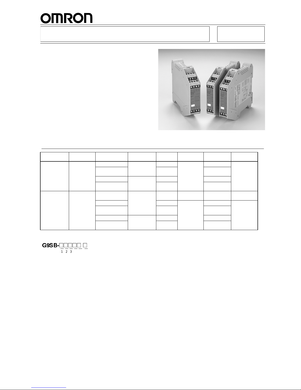
G9SB Safety Relay Unit
Ultra Slim Safety Relay Unit
■ Models of width 17.5 mm (smallest Unit in the
world as of January 2001) available with 2 or 3
poles. Models of width 22.5 mm with 3 poles also
available.
■ EN standards (TÜV approval) pending.
■ DIN track mounting possible.
Ordering Information
Model Num ber Legen d:
1. Function
None: Emergency stop
2. Contac t Con figuratio n (S a fet y O utp u t)
2: DPST-NO
3: 3PST-NO
3. Contact Configuration (OFF-delay Output)
0: None
4. Contact Configuration (Auxiliary Output)
0: None
1: SPST-NC
5. Input Configur a tio n
None: 1-channel or 2-channel input possible
0: None (direct breaking)
2: 2-chan ne l input
6. Miscellaneous
A: Auto-reset, inverse input
B: Auto-reset, + common input
C: Manual-reset, inverse input
D: Manual-reset, + common input
Main contacts Auxi liary
contact
Number of input
channels
Reset mode Input type Rated
voltage
Model Category
DPST-NO None 2 channels Auto-reset Inverse 24 VAC/VDC G9SB-2002-A 4
1 channel or 2
channels
+ common G9SB-200-B
2 channe ls Ma nu a l -r e se t Inverse G9SB-2 0 02 - C
1 channel or 2
channels
+ common G9SB-200-D
3PST-NO SPST-NC None (direct
breaking)
Auto-re s et -- - 24 VDC G9SB-30 10 3
2 channe ls Invers e 24 VAC /VDC G9SB- 30 12 - A 4
1 channel or 2
channels
+ common G9SB-301-B
2 channe ls Ma nu a l -r e se t Inverse G9SB-3 0 12 - C
1 channel or 2
channels
+ common G9SB-301-D
G9SB-
@@@@@ @
1 2 3 4 5 6
2
G9SB
G9SB
Specifications
■ Ratings
Power Input
Inputs
Note Indicates the current between terminals A1 and A2.
Contacts
■ Characteristics
Note: 1. The contact resistance was measured with 1 A at 5 VDC using the voltage-drop method.
2. The bounce time is not included in the figure for operating time.
3. The response time is the time it takes for the main contact to open after the input is turned OFF.
4. The insulation resistance was measured with 500 VDC at the same places that the dielectric strength was checked.
Item G9SB-200
@-@
G9SB-3010 G9SB-301@-
@
Power supply volta ge 24 VAC/VDC: 24 VAC, 50/60 Hz, or 24VDC
24 VDC: 24 VDC
Operati ng voltage
range
85% to 110% of rated power supply voltage
Power consumption 1.4 VA/1.4 W max. 1.7 W max. 1.7 VA/1.7 W max.
Item G9SB-200@-
@
G9SB-3010 G9SB-301@-
@
Input current 25 mA max. 60 mA max. (See note.) 30 mA max.
Item G9SB-200@-
@
G9SB-3010 G9SB-301@-
@
Resistive loa d (cos Φ=1)
Rated load 250 VAC, 5 A
Rated carry current 5 A
Item G9SB-200
@-@
G9SB-3010 G9SB-301@-
@
Contact resistance (See note 1.) 100 mΩ
Operating time (See note 2.) 30 ms max.
Response time (See notes 2 and 3.) 10 ms max.
Insulation resistance (See note 4.) 100 M
Ω min. (at 500 VDC)
Dielectric
strength
Between different outputs
2,500 VA C, 50/60 Hz for 1 min
Between inpu ts
and outputs
Between powe r
inputs and outputs
Vibration resistanc e 10 to 55 to 10 Hz, 0.375-mm single amplitude (0.75-mm double ampli tude)
Shock re s ist a nc e Destru ct i on
300 m/s
2
Malfunction
100 m/s
2
Durability Mechanical 5,000,000 op era tions min. ( at approx. 7,200 op er ations/hr)
Electrical 100,000 operations min. (at approx. 1,800 operations/hr)
Error rate, p-level (reference value) 5 VDC, 1 mA
Ambient operating temperature -25 to 55
°C (with no icing or condensation)
Ambient operating humidity 35% to 85% RH
Terminal tightening torque 0.5 N·m
Weight Approx. 115 g Approx. 135 g Approx. 120 g
Approved standards (pending) EN954-1, EN60204-1, UL508, CSA C22.2 No. 14
EMC (pending) EMI: EN55011 group 1 class A
EMS: EN50082-2
3
G9SB
G9SB
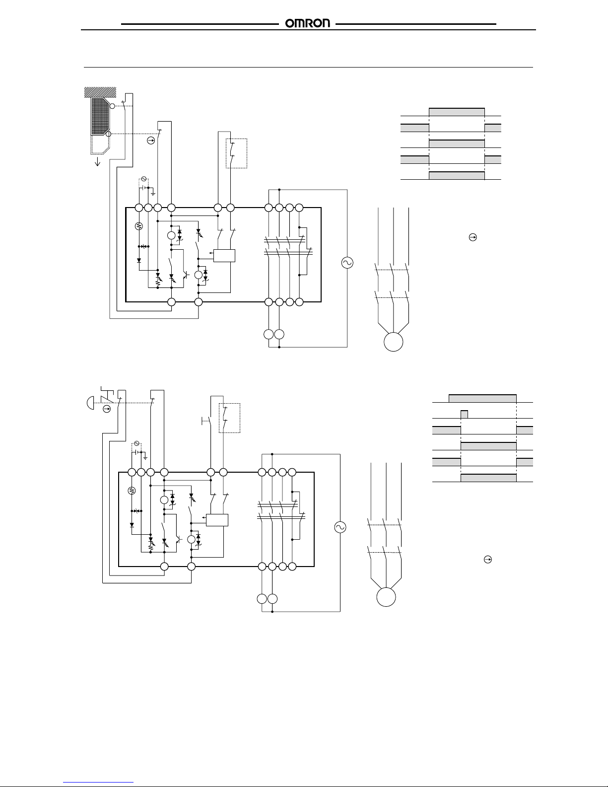
Application Examples
G9SB-2002-A (24 VAC/VDC) or G9SB-3012-A (24 VAC/VDC) with 2-channel Limit Switch Input/Auto-reset
Note External connections and timing charts for G9SB-200-B/301-B models are the same as those for G9SB-2002-A/3012-A models.
G9SB-2002-C (24 VAC/VDC) or G9SB-3012-C (24 VAC/VDC) with 2-channel Emergency Stop Switch Input/Manual-reset
Note External connections and timing charts for G9SB-200-D/301-D models are the same as those f or G9SB-2002-C/3012-D models.
KM1
KM2
M
11
KM1
KM2
12
23
24
S2
S1
KM1
KM2
K1
K2
K1
K1
K2
K2 K1
a
a
+
-
K2
TH
SA
A1 A2
T11 T12 T31 T32
13 23
㧔33㧕㧔41㧕
14 24
㧔34㧕㧔42㧕
T21
T22
㧖㧖
㧖㧖
Open
Control
circuit
Feedback loop
Timing Cha rt
Limit switches S1 and S2
K1 and K2 (NC)
K1 and K2 (NO)
KM1 and KM2 (NO)
S1: Safety limit swi tch with positive
opening mechanism (D4D or
D4B)
S2: Limit switch
KM1 and KM2: Magnetic Contactor (LC1D)
M: 3-phase motor
Note Only the G9SB-3012-A
model has terminals 33-34
and 41-42.
KM1 and KM2 (NC)
KM1
KM2
M
S2
KM1
KM2
21
22
S1
11
12
KM1
KM2
K1
K2
K1
K1
K2
K2 K1
a
a
+
-
K2
TH
SA
A1 A2
T11
T12 T31 T32
13 23
㧔33㧕㧔41㧕
14 24
㧔34㧕
㧖㧖
㧖㧖
㧔42㧕
T21
T22
Control
circuit
Feedback loop
Timing Chart
Emergency stop switch S1
K1 and K2 (NC)
K1 and K2 (NO)
KM1 and
KM2 (NC)
KM1 and
KM2 (NO)
S1: Emergency stop switch with
positive opening mechanism
(A165E, A22E)
S2: Reset switc h
KM1 and KM2: Magnetic Contactor (LC1D)
M: 3-phase motor
Note Only the G9SB-3012-C model
has terminals 33-34 and 41-
42.
Reset switch S2
Note Output turns ON with the ris-
ing edge of reset switch S2,
but wil l not ope r ate if t her e i s a
short breakdown in S2 .
 Loading...