

Page 1
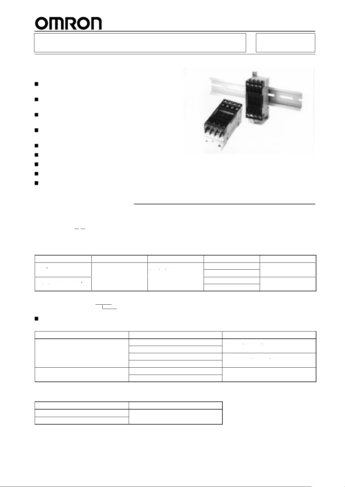
Terminal Relay
eayou u
SS O
s ead sc e
G6
o e OS e ay
G3
G6
G6 (see o e)
G6 (see o e)
G3
G3 6
G6D-F4B
G6D
SB
G3DZ-F4B
Easy-to-use, Space-saving Terminal
Relay with Four-point Output
Almost the same size as PYF Socket: 31 x 35 x
68 mm (W x H x D)
Each terminal circuit (with coil or contact) is
independent from one another.
Short
Bar ensures easy connection
adjacent terminals.
Provided with a terminal cover that prevents
electric-shock accidents.
Relay and MOS FET relay models are available.
LED operation indicator.
Built-in diode absorbs coil surge.
Mounts either on DIN track or screws.
Tool for easy mounting or removal of Relays
provided.
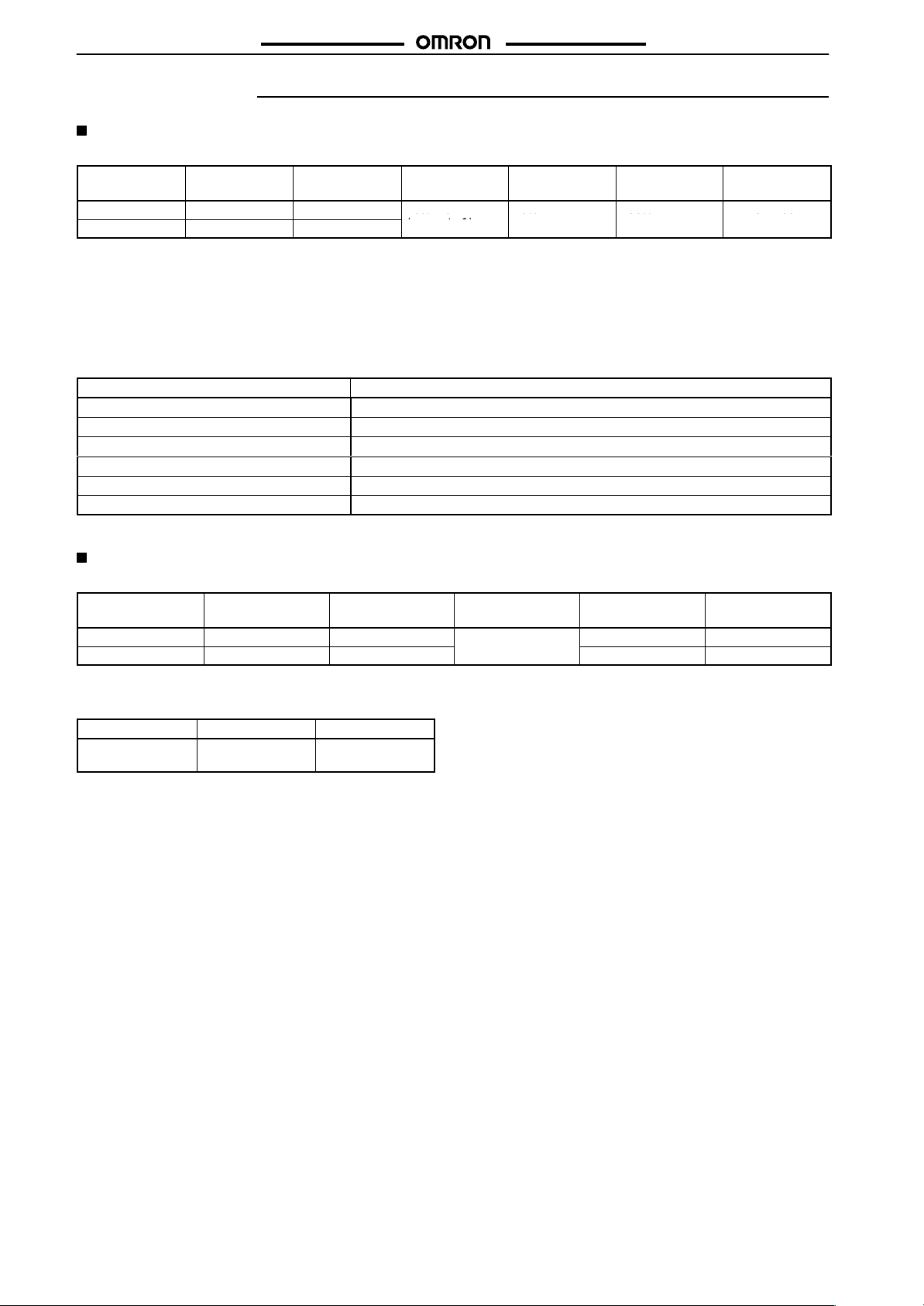
Ordering Information
of common and
G6D-F4B/G3DZ-F4B
Model Number Legend:
G6D/G3DZ-jj
12
1. Terminal
F:
Relay output
Power MOS FET relay
output
Note:
Form
Flat type
Output
When ordering add the rated coil voltage to the model number
Example: G6D-F4B 24 VDC
Contact configuration
SPST-NO
4
Rated coil voltage
Accessories (Order Separately)
Replacement Relays
Applicable Terminal Relay
G6D-F4B
G3DZ-F4B
12 VDC
24 VDC
12 VDC
24 VDC
12 VDC
24 VDC
2.
Terminals
Phillips head screw
terminal
.
Rated voltage
Number of Relays Mounted
4B: 4
Rated coil voltage
12 VDC
24 VDC
12 VDC
24 VDC
G6D-1A (see note)
G6D-1A-AP (see note)
G3DZ-2R6PL
Model
G6D-F4B
G3DZ-F4B
Model
Note:
Short
Error rate (P level) for the G6D-1A is 5 V at 10 mA and that for the G6D-1A-AP is 5 V at 1 mA.
Bar
Applicable Terminal Relay
-4-
Model
1
Page 2
G6D-F4B/G3DZ-F4B
0% a
0%
30%
o00
C
Specifications
Ratings
Coil Ratings (per G6D Relay)
Rated
voltage
12 VDC
24 VDC
Rated current
18.7 mA
10.5 mA
Coil resistance
720
Ω
2,880
Ω
Must operate
voltage
70% max.
(see note 1)
Must release
voltage
10% min.
G6D-F4B/G3DZ-F4B
Max. voltage
130%
consumption
Approx. 200 mW
Power
Note: 1.
The must operate voltage is 75% or less of the rated voltage if the Relay is mounted upside down.
2.
Rated current and coil resistance were measured at a coil temperature of 23°C with a tolerance of
Operating characteristics were measured at a coil temperature of 23
3.
4. The maximum allowable voltage is the maximum value of the allowable voltage range for the relay coil operating power supply.
There is no continuous allowance.
5.
The rated current includes the terminal’
s LED current.
°C.
±10%.
Contact Ratings (per G6D Relay)
Item Resistive
Rated load
Rated carry current
Max. switching voltage
Max. switching current
Max. permissible capacity (reference value)
Error rate (reference value) (see note)
Note:
This value is for a switching frequency of 120 times per minute.
3 A at 250 V
5 A
250 V
5 A
1,250 V
5 VDC, 1 mA
AC, 3 A at 30 VDC
AC, 30 VDC
A, 150 W
load (cosφ = 1)
Power MOS FET Relay Specifications
Input (per G3DZ Power MOS FET Relay)
Rated
voltage
12 VDC
24 VDC
Note:
The rated current includes the terminal’
Output (per G3DZ Power MOS FET Relay)
Load
voltage
3 to 264 V
3 to 125 VDC
AC
Operating voltage
9.6 to 14.4 VDC
19.2 to 28.8 VDC
Load current
100 µ to 0.3 A
Must operate
voltage level
9.6 VDC max.
19.2 VDC max.
s LED current.
Inrush current
6 A (10 ms)
Must release
voltage level
1 VDC min.
Input impedance
2 kΩ±20%
4 kΩ±20%
Rated current
8.0 mA
8.2 mA
±20%
±20%
2
Page 3
G6D-F4B/G3DZ-F4B
e
eec cs e g
Soc essace
e e pec a cy
e
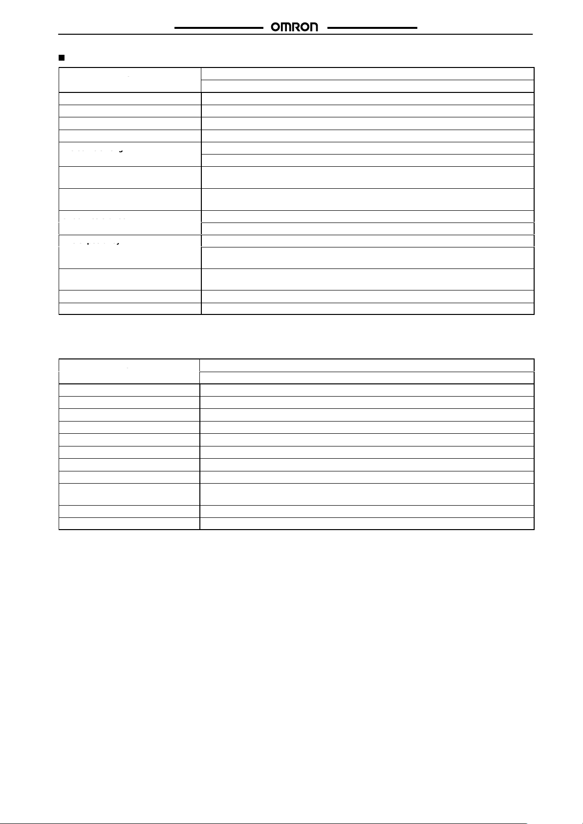
Characteristics
Item
Contact resistance (see note 2)
Must operate time (see note 3)
Release time (see note 3)
Insulation resistance
Dielectric strength
Impulse withstand voltage (between
coil and contacts)
V
ibration resistance
Shock resistance
Life expectancy
Ambient temperature
Ambient humidity
Weight
G6D-F4B
Relay output
100 mΩ max.
10 ms max.
10 ms max.
1,000 MΩ min. (at 500 VDC)
2,000 V
AC, 50/60 Hz for 1 min between coil and contacts.
750 V
AC, 50/60 Hz for 1 min between contacts of same polarity
4,000 V (1.2 50
Destruction:
Malfunction:
Destruction:
Malfunction:
Mechanical:
Electrical:
Operating: –25°
Storage: –25°
Operating:
Approx. 65 g
µs)
10 to 55 Hz, 1.5-mm double amplitude
10 to 55 Hz, 1.5-mm double amplitude
2
500 m/s
2
100 m/s
20,000,000 operations min. (at 18,000 operations/hr)
100,000 operations min. (3 A at 250 V
100,000 operations min. (3 A at 30 VDC, resistive load) (at 1,800 operations /hr)
C to 55°C (with no icing)
C to 55°C (with no icing)
45% to 85%
G6D-F4B/G3DZ-F4B
AC, resistive load)
Note: 1.
Must operate time
Release time
Output ON-resistance
Leakage current at OFF state
Insulation resistance
Dielectric strength
V
ibration resistance
Shock resistance
Ambient temperature
Ambient humidity
Weight
The above values are initial values.
2.
Measurement condition: 1 A at 5 VDC
3.
Ambient temperature condition: 23
Item
°C
G3DZ-F4B
Power MOS FET relay output
10 ms max.
15 ms max.
2.4 Ω max.
10 µA max. (at 125 VDC)
100 MΩ min. (at 500 VDC)
2,000 V
AC, 50/60 Hz for 1 min between input and output terminals
10 to 55 Hz, 1.5-mm double amplitude
2
500 m/s
Operating: –25°
Storage: –25°
Operating:
Approx. 65 g
C to 55°C (with no icing)
C to 55°C (with no icing)
45% to 85%
3
Page 4

G6D-F4B/G3DZ-F4B
Engineering Data
G6D-F4B
Max. Switching Capacity Life Expectancy
G6D-F4B/G3DZ-F4B
DC resistive load
Switching current (A)
AC resistive load
Switching
voltage (V)
G3DZ-F4B
Load Current vs. Ambient Temperature
Characteristics
Load current (A)
4
Life expectance (x10 operations)
250 VAC/30 VDC resistive load
Switching current (A)
Inrush Current Resistivity
Non-repetitive (Keep
Inrush current (A. Peak)
the inrush current to half the rated value
if it occurs repetitively.)
Ambient temperature (
°C)
Energizing time (ms)
4
Page 5

G6D-F4B/G3DZ-F4B
G6 S
Dimensions
Note:
All units are in millimeters unless otherwise indicated.
G6D-F4B
G3DZ-F4B
68
max.
16, M3 Phillips
head screws
Mounting
Dimensions
Two, 4 dia. or M3.5 holes
Input side
Output side
G6D-F4B/G3DZ-F4B
Terminal
Internal Connections
(T
op V
iew)
Arrangement/
Accessories
G6D-4-SB Short Bar
31 max. 35 max.
Note: Make
of
the coil is correct.
Applicable
model
G6D-F4B
G3DZ-F4B
sure
that the polarity
Model
G6D-4-SB
5
Page 6

G6D-F4B/G3DZ-F4B
Precautions
Wiring
Be
sure to turn OFF the power when wiring the Unit and
the
charged terminals of the Unit. Otherwise, an electric shock may
result.
Do not apply overvoltage to the input terminals. Otherwise, the Unit
may
malfunction or burn.
Relay Models
Do
not connect the Unit to loads exceeding the rated switching ca
pacity (switching voltage or current). Otherwise, faulty insulation,
contact
weld, or faulty contact of Relays, or damage to Relays may
result,
or the Relays may malfunction or burn.
The life of Relays varies with the switching condition. Test the
Relays under the actual operating conditions before using the
Relays
within the
riorated Relays may result in the faulty insulation of the Relays or
cause
the Relays to burn.
Do
not use the Unit in locations with inflammable gas. Otherwise, a
fire or explosion due to the heat of the Relays or sparks from the
may result when they are switched.
Relays
permissible switching frequency
SSR Output (Power MOS FET Relay Model)
Do
not connect the Unit
ing the rated output current of the Unit. Otherwise, the output element
of the Unit may be damaged and a short or open-circuit mal
may result.
function
If
the Unit is connected to a DC
Unit to protect the Unit from counter-electromotive voltage, otherwise
the counter-electromotive voltage may damage the output ele
and a short or open-circuit malfunction may result.
ment
to loads consuming a total current exceed
inductive load, connect a diode to the
Correct Use
Mounting
When
mounting two or more Units, reduce the current and ON duty
and
provide an appropriate
ambient
temperature will not exceed 55
Relay Replacement
Use the Relay Removal Tool provided with the Unit to dismount a
Relay.
Be
sure to turn OFF the power to the Unit before
mounting a Relay
When
terminals will come in contact with the socket contact pins properly
Do
not mount Relays that are dif
Wiring
Pay utmost attention not to make mistakes with the polarity of the
input
terminals.
distance between the Units so that the
°C.
, insert the Relay vertically so that the relay
ferent to one another in voltage.
do not touch
. The use of dete
replacing a Relay
-
-
-
-
-
.
.
G6D-F4B/G3DZ-F4B
Coil Voltage
Make
sure not to impose
on
the coil continuously
Do not connect any inductive load in parallel to the coil input as
shown
in the following example or power supply with
age. Otherwise, the surge absorption diode will be damaged.
Do Not Use the Following Circuit
Inductive load
Handling
Do
not drop, shock, or vibrate
age
to the Unit may result or the Unit may malfunction.
Make sure that all the Relays are properly mounted before use.
Screw Tightening Torque
Tighten
each terminal screw to a torque of 0.78 to 1.18N S m.
T
ighten each mounting screw to a torque of 0.59 to 0.98 N S m.
Installation Environment
Do
not install the Unit in the following locations. Otherwise, damage
to
the Unit may result or the Unit may malfunction.
Locations with direct sunlight.
Locations with an ambient temperature range not within –25°C to
55°C.
Locations with rapid temperature changes resulting in condensa-
tion or locations with relative humidity ranges not within 45% to
85%.
Locations
Locations with excessive dust, salinity
Locations with vibration or shock af
Locations with water
with corrosive or inflammable gas.
Disassembly, Repair, and Modification
Do
not disassemble, repair
tric
shock may result or the Unit may malfunction.
voltage exceeding the permissible voltage
.
a surge volt
G6D coil
the Unit excessively
, oil, or chemical sprayed on the Unit.
, or modify the Unit. Otherwise, an elec
Coil surge
absorption
diode
. Otherwise, dam
, or metal powder
fecting the Unit.
.
-
-
-
6
Page 7

G6D-F4B/G3DZ-F4B
G6D-F4B/G3DZ-F4B
7
Page 8

G6D-F4B/G3DZ-F4B
G6D-F4B/G3DZ-F4B
ALL DIMENSIONS SHOWN ARE IN MILLIMETERS.
To
convert millimeters into inches, multiply by 0.03937. T
o convert grams into ounces, multiply by 0.03527.
Cat. No. J115-E1-1 In the interest of product improvement, specifications are subject to change without notice.
OMRON Corporation
Industrial
Industrial Control Components Division
28th Fl., Crystal T
1-2-27, Shiromi, Chuo-ku,
Osaka 540-6028 Japan
Phone: (81)6-6949-6025 Fax: (81)6-6949-6029
8
Automation Company
ower Bldg.,
Printed
in Japan
0799-1M (0799)
a
 Loading...