

Page 1
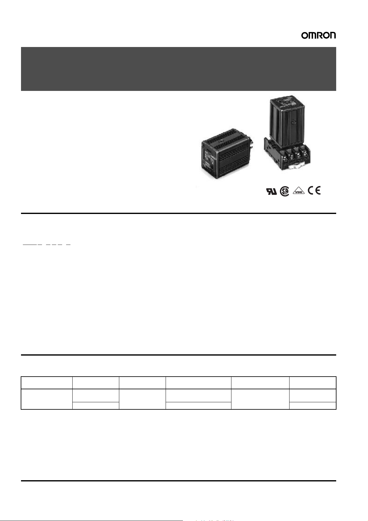
Solid State Relays G3@-VD
G3B/G3BD
Refer to Warranty and Application Considerations (page 1), Safety
Precautions (page 4), and Technical and Safety Information (page 6).
International Standards for G3B Series,
Same Profile as MK Power Relays
• Shape-compatible with mecha ni cal relays.
• Certified by UL, CSA, and VDE (models numbers with a suffix
of “-VD”).
• Plug-in type, same size as MK Power Relays.
• Operation indicator provided to confirm input.
• DC Output model available with 3 to 125-VDC load voltage
range for high-voltage applications.
Model Number Structure
■Model Number Legend
G3B@-@@@-@
234
1
1. Basic Model Name
G3B: Solid State Relay
2. Load Power Supply Type
Blank: Switches AC loads
D: Switches DC loads
3. Rated Load Power Supply Voltage
2: 200 V
1: 100 V
4. Rated Load Current
03: 3 A
05: 5 A
56
5. Terminal Type
S: Plug-in terminals
6. Certification
VD: Certified by UL, CSA, and VDE
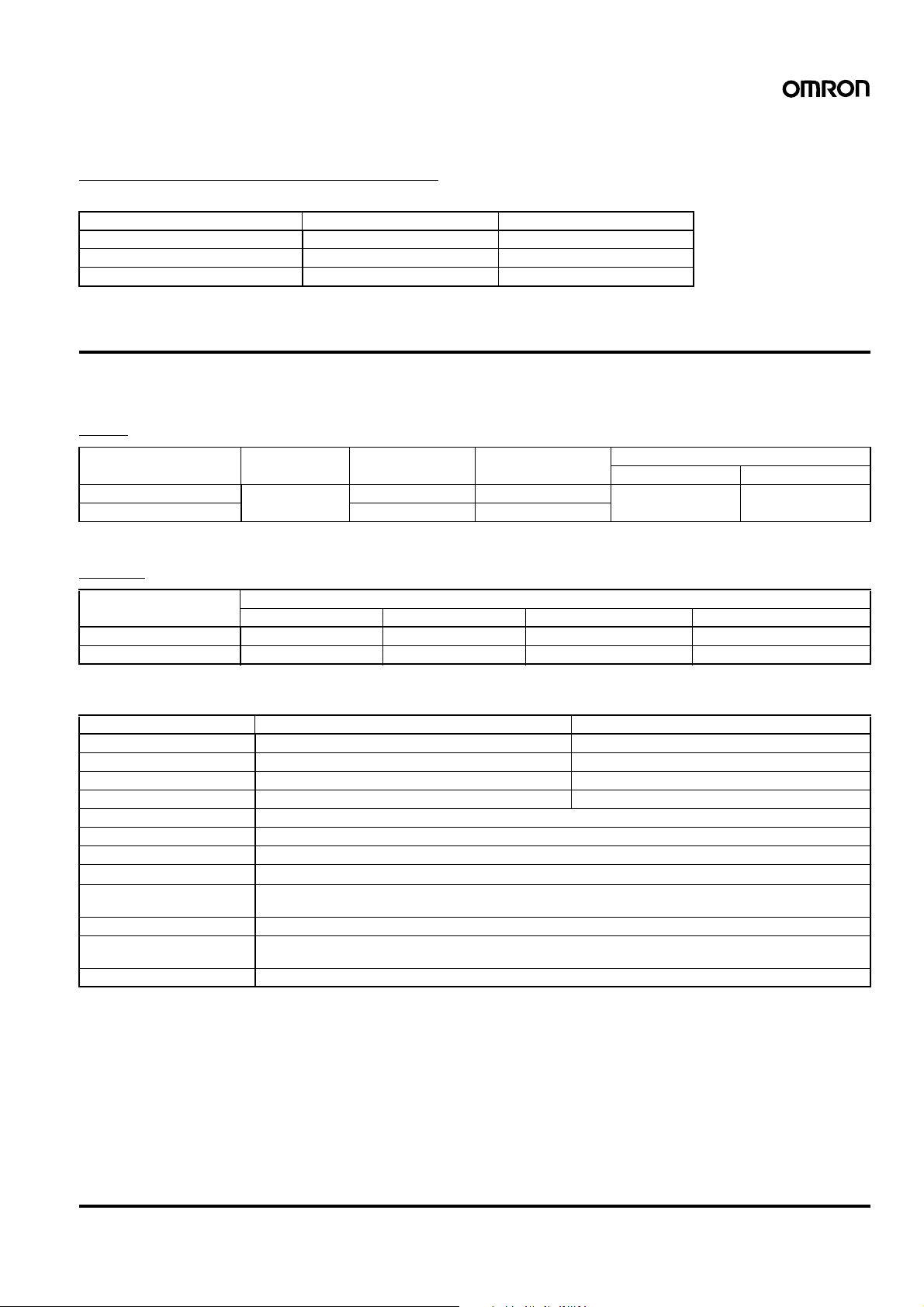
Ordering Information
■List of Models
Isolation Zero cross
function
Photocoupler Yes Yes 5 A at 100 to 240 VAC
No 3 A at 5 to 110 VDC G3BD-103S-VD
Note: 1. Product is labelled “250 VAC”.
2. When ordering, specify the rated input voltage.
Indicator Rated output load Rated input voltage Model
(See note.)
5 to 24 VDC G3B-205S-VD
220 Solid State Relays G3@-VD G3B/G3BD
Page 2
■Accessories (Order Separately)
Connecting Sockets/Hold-Down Clips
Refer to page 297 for details.
Item PF083A-E PL-08
Connecting Front connecting Back connecting
Mounting method/Terminal type Track mounted/screw terminals Solder terminals
Hold-down clip PYC-A1 (when track mounted) PLC
Specifications
■Ratings (at an Ambient Temperature of 25°C)
Input
Model Rated voltage Operating voltage Inp ut current Voltage levels
Must operate voltage Must release voltage
G3B-205S-VD 5 to 24 VDC 4 to 32 VDC 15 mA max. (See note.) 4 VDC max. 1 VDC min.
G3BD-103S-VD 4 to 30 VDC 15 k
Note: Constant-current input circuit.
Output
Ω+20%/−10%
Model Applicable load
Rated load voltage Load voltage range Load current Inrush current
G3B-205S-VD 100 to 240 VAC 75 to 264 VAC 0.1 to 5 A 80 A, 60 Hz for 1 cycle
G3BD-103S-VD 5 to 110 VDC 3 to 125 VDC 0.1 to 3 A 12 A (10 ms)
■Characteristics
Model G3B-205S-VD G3BD-103S-VD
Operate time 1/2 cycle of load power source + 1 ms max. 0.5 ms max.
Release time 1/2 cycle of load power source + 1 ms max. 2.5 ms max.
Output ON voltag e drop 1.6 V (RMS) max. 1.5 V max.
Leakage current 5 mA max. (at 100 VAC); 10 mA max. (at 200 VAC) 5 mA max. (at 125 VDC)
Insulation resistance 100 M
Dielectric strength 2,000 VAC, 50/60 Hz for 1 min
Vibration resistance Destruction: 10 to 55 to 10 Hz, 0.75-mm single amplitude
Shock resistance
Ambient temperature Operating: –30°C to 80°C (with no icing or condensation)
Ambient humidity 45% to 85%
Certified standards G3B: UL508, CSA C22.2 No. 14, EN60947-4-3
Weight Approx. 70 g
Ω min. (at 500 VDC)
1,000 m/s
Storage: –30
G3BD: UL508, CSA C22.2 No. 14, EN60950
2
°C to 100°C (with no icing or condensation)
Solid State Relays G3@-VD G3B/G3BD 221
Page 3

Engineering Data
Load Current vs. Ambient Temperature
Characteristics
G3B-205S-VD, G3BD-103S-VD
G3B-205S-VD
G3BD-103S-VD
Load current (A)
Ambient temperature (°C)
Dimensions
Note: All units are in millimeters unless otherwise indicated.
G3B-VD
G3BD-VD
One Cycle Surge Current:
Non-repetitive
Non-repetitive (Keep the inrush current to half the rated value
if it occurs repetitively.)
G3B-205S-VD, G3BD-103S-VD
G3B-205S-VD
Inrush current (A. Peak)
G3BD-103S-VD
Energized time (ms)
Terminal Arrangement
(Bottom View)
35 max.
35 max.
Mounting Height with socket
Front Connecting Socket
G3B
76.8
73.5
PF083A
52.5 max.
Back Connecting Socket
G3B
56.5
PL08
−
(−)
Load
Input voltage
Input
(+)
+
( )
Load
power
supply
Load
Note: The symbols shown in parentheses
are for DC loads.
Note: When mounting PF083A,
mount the key track down.
222 Solid State Relays G3@-VD G3B/G3BD
Page 4

Safety Precautions
■Precautions for Correct Use
Please observe the following precautions to prevent failure to
operate, malfunction, or undesirable effect on product performance.
The SSR case serves to dissipate heat. Install the relays so that they
are adequately ventilated. If poor ventilation is unavoidable, reduce
the load current to half.
Cat. No. K051-E1-05
ALL DIMENSIONS SHOWN ARE IN MILLIMETERS.
To convert millimeters into inches, multiply by 0.03937. To convert grams into ounces, multiply by 0.03527.
In the interest of product improvement, specifications are subject to change without notice.
Solid State Relays G3@-VD G3B/G3BD 223
 Loading...