


Power Relay
G2A
Highly Reliable, 4-pole Miniature Relay Ideal
for Sequence Control
• Card lift-off employed for greater life and stable quality.
• Long endurance and stable quality are assured by card lift-off
system.
• Mounting interchangeability with MY-series Relays.
• Operation indicator mechanism incorporated for at-a-glance
monitoring of ON/OFF operation. In addition, a built-in operation
indicator model is also included in this Relay Series.
Ordering Information
Classification Plug-in terminals/Solder terminals PCB terminals
Standard model G2A-432A G2A-4321P
Arc barrier equipped model G2A-432AY ---
Built-in diode model G2A-432A-D G2A-4321P-D
Built-in operation indicator model G2A-432A-N ---
Built-in operation indicator and diode model G2A-432A-N1 ---
UL-
approved
model
Standard model G2A-432A-US G2A-4321P-US
Arc barrier equipped model G2A-432AY-US ---
Note: 1. When placing your order, add the coil voltage rating listed in the specifications to the model number as shown below.
2. Built-in diode model and the operating coil of the G2A-432A-N1 are available only with DC ratings.
3. The Latching Relay (G2AK) and Fully sealed Relay (G2A-434A) developed based on the G2A are also available in this se ries.
Example: G2A-432A 100/110 VAC
Rated coil voltage
Model Number Legend
G2A-@@@@@-@
1. Number of Poles and Contact Form
2. Contact Type
3. Enclosure Construction
4. Terminal Shape
Note: 1. The coil of the G2A-432A-N1 or a built-in diode model operates with DC only.
1 2 3 4 5 6
5. Safety Breaking Mechanism
4: 4PDT
3: Crossbar bifurcated
2: Casing
A: Plug-in
1P: PCB
2. The G2A Series include the G2A-434A Power Relay and G2AK Latching Relay. Refer to page 133 for details.
3. Built-in indicator models satisfying international standards are available. Contact your OMRON representative for details.
None: No
Y: Arc barrier
6. Special Element
None: Standard
D: Built-in diode
N: Built-in operation indicator
N1: Built-in operation indicator and diode
US: UL-approved
Power Relay G2A 119
■ Relays Other than Standard Models
Arc barrier equipped Built-in diode Built-in operation indicator
G2A-432AY G2A-432A-D G2A-432A-N
The arc barrier equipped model is
a relay designed to prevent arc
short-circuiting between phases
and can be used in a circuit which
has potential difference between
phases. The switching power of
such a circuit with potential difference must be limited to less than
1/2 the rated load when using this
Relay.
The built-in diode model is a relay
which incorporates a diode for absorption of the reverse voltage
that may be generated when the
coil is de-energized. Because the
release time of this model is longer than the standard model, pay
adequate attention to this point in
designing a circuit. Also, pay attention to the + polarity of the coil.
The reverse-breakdown voltage
of the diode is 1,000 V.
The built-in operation indicator
model has a newly added operation indicator to the conventional
operation indication mechanism
and facilitates operation monitoring without being affected by ambient illumination.
With the -N model (rated at 16,
12, 24, and 48 VDC) and -N1
model rated at 6, 12, 24, 48, and
100 VDC), pay attention to the +
polarity of the coil.
■ Accessories
Sockets
Track mounting Front-connecting
Screw terminals Solder terminals Wire-wrap terminals PCB
PYF14A PYF14(-E), PYF14A-
Note: With monitor terminal.
Socket
TU, PYF14T
Without Hold-
down Clip
PY14, PY14-3
(see note)
With Hold-down
Clip
PY14-Y2 PY14QN(2) PY14QN(2)-Y2 PY14-0,
Without Hold-
down Clip
With Hold-down
Clip
terminals
PY14-02
Relay Hold-down Clips Socket Mounting Plates
For Front-connecting Socket PYC-A2
For Back-connecting Socket PYC-3/PYC-5
For Socket Mounting Plate PYC-2
For one Socket PYP-1
For 18 Sockets PYP-18
For 36 Sockets PYP-38
Specifications
■ Coil Ratings
The rated currents for some of the built-in operation indicator models differ from the values given in this table. Refer to note 5 below.
Rated
voltage
6 VAC 295 mA 233 mA 8.9
12 VAC 148 mA 117 mA 34
24 VAC 73 mA 58 mA 136
50 VAC 35 mA 28 mA 530
100/
110 VAC
200/
220 VAC
6 VDC 176 mA 34
12 VDC 88 mA 136
24 VDC 45 mA 530
48 VDC 22 mA 2,200
100 VDC 11.4 mA 8,800
Rated current Coil
50 Hz 60 Hz Armature
17.7/
21.4 mA
8.9/
10.8 mA
14/
16.8 mA
7/8.4 mA 8,800
resistance
Ω 0.048 H 0.065 H 80 % max. 30 % min. 110 % Approx. 1.4 VA
Ω 0.166 H 0.257 H
Ω 0.691 H 1.04 H
Ω 3.08 H 4.53 H
2,200
Ω 12.42/
12.38 H
Ω 42.2/
41.8 H
Ω 0.14 H 0.26 H 10 % min. 110 % Approx. 1.1 W
Ω 0.6 H 1.0 H
Ω 2.7 H 4.6 H
Ω 11 H 19 H
Ω 43 H 73 H
Coil inductance (ref.
value)
OFF
Armature
ON
18/16.4 H
72/65.5 H
Must
operate
Must
release
% of rated voltage
Max.
voltage
Power
consumption
Note: 1. The rated current and coil resistance are measured at a coil temperature of 23
±15% for DC coil resistance.
2. The AC coil resistance and coil inductance values are for reference only.
3. Performance characteristic data is measured at a coil temperature of 23
4. The maximum voltage is one that is applicable instantaneously to the Relay coil at an ambient temperature of 23
5. For built-in operation indicator models rated at 6, 12, and 24 VDC, add an LED current of approx. 5 mA to the rated currents.
°C with tolerances of +15%/–20% for AC rated current and
°C.
120 Power Relay G2A
°C and not continuously.
■ Contact Ratings
Load Resistive load (cosφ = 1) Inductive load (cosφ = 0.4) (L/R = 7 ms)
Contact type Crossbar bifurcated
Contact material Movable: AgAu-clad AgPd
Rated load 0.3 A at 110 VAC
Rated carry current 3 A
Max. switching power 250 VAC, 125 VDC
Fixed: AgPd
0.5 A at 24 VDC
0.2 A at 110 VAC
0.3 A at 24 VDC
■ Characteristics
Classification Standard/Acr barrier equipped/Built-in operation
Contact resistance
(see note 2)
Operate time (see note 3) 15 ms max.
Release time (see note 3) 15 ms max. 30 ms max.
Max. operating frequency Mechanical: 18,000 operations/hour
Insulation resistance
(see note 4)
Dielectric strength 1,500 VAC, 50/60 Hz for 1 min between coil and contacts and contacts of different polarities (700 VAC be-
Vibration resistance Destruction: 10 to 55 to 10 Hz, 0.75 mm single amplitude (1.5 mm double amplitude)
Shock resistance
Error rate (level P)
(Reference value)
(see note 6)
Endurance Mechanical: 100,000,000 operations min. (at operating frequency of 18,000 operations/hour)
Ambient temperature Operating:–10
Ambient humidity Operating:5% to 85%
Weight Approx. 38 g
Note: 1. The data shown above are initial values.
2. The contact resistance was measured with 0.1 A at 5 VDC using the voltage drop method.
3. The operate or release time was measured with the rated voltage imposed with any contact bounce ignored at an ambient temperature
of 23
°C.
4. The insulation resistance was measured with a 500-VDC megger applied to the same places as those used for checking the dielectric
strength.
5. The electrical endurance was measured at an ambient temperature of 23
6. This value was measured at a switching frequency of 60 operations per minute.
100 m
Electrical: 1,800 operations/hour (under rated load)
100 M
tween contacts of same polarity)
Malfunction: 10 to 55 to 10 Hz, 0.5 mm single amplitude (1.0 mm double amplitude)
Destruction: 1,000 m/s
Malfunction: 100 m/s
1 mA at 100 mVDC
Electrical: 5,000,000 operations min. (under rated load and at operating frequency of
indicator models (G2A-@-N)
Ω max.
Ω min. (at 500 VDC)
2
2
1,800 operations/hour) (see note 5)
°C to 40°C (with no icing or condensation)
°C.
Built-in diode/Built-in operation indicator models
(G2A-@-N1)
■ Approved by Standards
UL508 (File No. E41515)
Model Coil ratings Contact ratings
G2A-@-US 6 to 120 VAC
6 to 120 VDC
1 A 120 VAC (resistive load)
1 A 30 VDC (inductive load)
Power Relay G2A 121

Engineering Data
Maximum Switching Power Endurance
10,000
DC resistive load
5,000
24-VDC resistive load
AC resistive load
AC inductive load
(cosφ = 0.4)
Switching current (A)
DC inductive load
L/R = 7 ms
Switching voltage (V)
Ambient Temperature vs.
Must-operate and Must-release
Voltage
G2A AC (60 Hz)
Must-operate
Number of Relays: 5
Must-operate and reset voltage (%)
voltage
Must-release
voltage
3
1,000
500
100
50
Endurance (x10 operations)
10
Ambient Temperature vs.
Coil Temperature Rise
G2A 110 VAC (50 Hz)
Contact
Number of Relays: 5
°
Coil temperature rise ( C)
carry current
24-VDC
inductive load
L/R = 7 ms
110-VAC
resistive load
110-VAC
inductive load
cosφ = 0.4
Switching current (A)
Malfunctioning Shock
G2A-432A 100/110 VAC
Not energized
Energized
G2A DC
Number of Relays: 5
Must-operate and reset voltage (%)
Ambient temperature (°C)
Must-operate
voltage
Must-release
voltage
Ambient temperature (°C)
G2A DC
°
Coil temperature rise ( C)
Ambient temperature (°C)
Number of Relays: 5
Ambient temperature (°C)
Contact
carry current
Shock direction
Number of samples = 5
Measurement conditions: Impose a shock of
2
100 m/s
in the ±X, ±Y, and ±Z directions three
times each with the Relay energized and not
energized to check the shock values that cause
the Relay to malfunction.
Unit: m/s
2
122 Power Relay G2A

Contact Reliability
(JIS C 4530 Allen-Bradley Test Circuit)
100 VAC
λ60
= 0.00153 × 10
Ω
−
6
Carry contact
Break contact
Make contact
Self-holding
contact
24 VDC
λ60
Ω
= 0.00153 × 10
Contact Reliability
(Improved Allen-Bradley Test Circuit)
Contact load: 1 mA at 5 VDC (resistive load)
Failure criterion contact resistance: 100 Ω
−
−
6
Carry contact
Break contact
Make contact
Self-holding
contact
Ω
λ60
= 0.00153 × 10
6
Carry contact
Break contact
Make contact
Self-holding
contact
Contact resistance (m )
Operations (x 10
4
)
Contact resistance (m )
Operations (x 10
Coil Self-load Life Curve
(Unit: mA)
Model Specifications No. of Relays
123510
G2A-432A 100 VAC, 60 Hz 14 28 42 70 140
24 VDC 45 90 135 225 450
Relay Mounting Adjacent Distance vs. Coil Temperature Rise
G2A-432A 24 VDC
Condition: The
°
saturated coil
temperature is
measured with rated
coil voltage
(24 VDC) imposed.
Coil temperature rise ( C)
Relay
mounting
position
Average of No. 1 and No. 3
Average of No. 4. and No. 6
Upper
Lower
110 VAC
Condition: The saturated
°
coil temperature is
measured with rated
voltage (110 VAC) at 60 Hz
imposed.
Coil temperature rise ( C)
4
)
4
Life (x10 )
Relay
mounting
position
Contact resistance (m )
Number of Relays
Upper
Lower
Operations (x 10
100 VAC
24 VDC
4
)
Average of No. 7 and No. 9
Mounting adjacent distance l (mm)
Average of No. 1 and No. 3
Average of No. 4. and No. 6
Average of No. 7 and No. 9
Mounting adjacent distance l (mm)
Power Relay G2A 123

Accessories (Order Separately)
Connecting Sockets
Front-connecting
Back-connecting Socket
Socket
DIN track/screw
Solder terminals Wire-wrap terminals PCB terminals
mounting
PYF14A(-E)
PYF14A-TU
PYF14T
PY14
PY14-Y3
PY14-Y2
(with Relay
Hold-down Clip)
PY14QN(2)
PY14QN(2)-Y2
(with Relay
Hold-down Clip)
PY14-0
PY14-02
Note: 1. The PYF@A-TU is a high-humidity relay with nickel-plated rustproof terminal screws that are the same as the PYF@A in size.
2. The PYF14T is slightly different from the PYF14A(-TU) in shape and size.
3. The PYF@A-E is a finger-protection model, for which round terminals are not available. Use fork-shaped terminals or equivalent ones
instead.
PY14-3 Back-connecting Socket
(with check terminals for operation monitoring)
81
56
28
Check terminal for operation monitoring
Built-in operation monitoring lamp possible
38.5
9 (7.7)
2
0.3
34.5±0.4
36
+0.3
−0
Panel Cutout
+0.3
78
−0
+0
77.5
−0.4
2-dia. hole
Three, 1.2-dia. holes
Shorting lead
Relay Mounting Height with Socket
With Front-connecting Socket
G2A
76.5
Note: PYF14A can be used for both DIN
PYF14A
track mounting and screw mounting.
73
With Back-connecting Socket
G2A
45.5
PY14 Socket
Relay Hold-down Clips
For Front-connecting Socket For Back-connecting Socket For Socket mounting plate
PYC-A2
PYC-3
Note: When using a Relay Hold-down Clip for the built-in operation indicator model, use of the PYC-A2 or PYC-5, which allows easy viewing of
the indicator, is recommended.
PYC-5
PYC-2
124 Power Relay G2A

Dimensions
Note: 1. All units are in millimeters unless otherwise indicated.
2. Dimensional tolerances are
±0.1 mm.
Solder Terminal Models PCB Terminal Models
2.6
21.5 max.
Fourteen, 1.2-dia. 1.2 holes x 3 elliptic holes
0.5
28.5 max.
1.8
42.5 max.
5.4
42.5 max.
Terminal Arrangement/Internal Connections
(Bottom View)
Standard Models Make-before-break
Contact Models
Arc Barrier Equipped Models Built-in Diode Models
Built-in Operation Indicator Models
Color of operation indicator
AC model: Red
DC model: Green
G2A-432A-N
100/110, 200/220 VAC
6, 12, 24, 50 VDC
6, 12, 24 VDC
48, 100 VDC
1.8
0.5
1
21.5 max.
2.6
0.5
28.5 max.
4
Mounting Holes on PCB
(Bottom View)
5
Fourteen, 1.5-dia. holes
4.1
12.65
6.35
7.3
4.4
4.4
13.2
G2A-432A-N1
6, 12, 24 VDC
48, 100 VDC
Note: Do not reverse the polarity of the coil of DC Relays that have a built-in indicator or diode.
Power Relay G2A 125
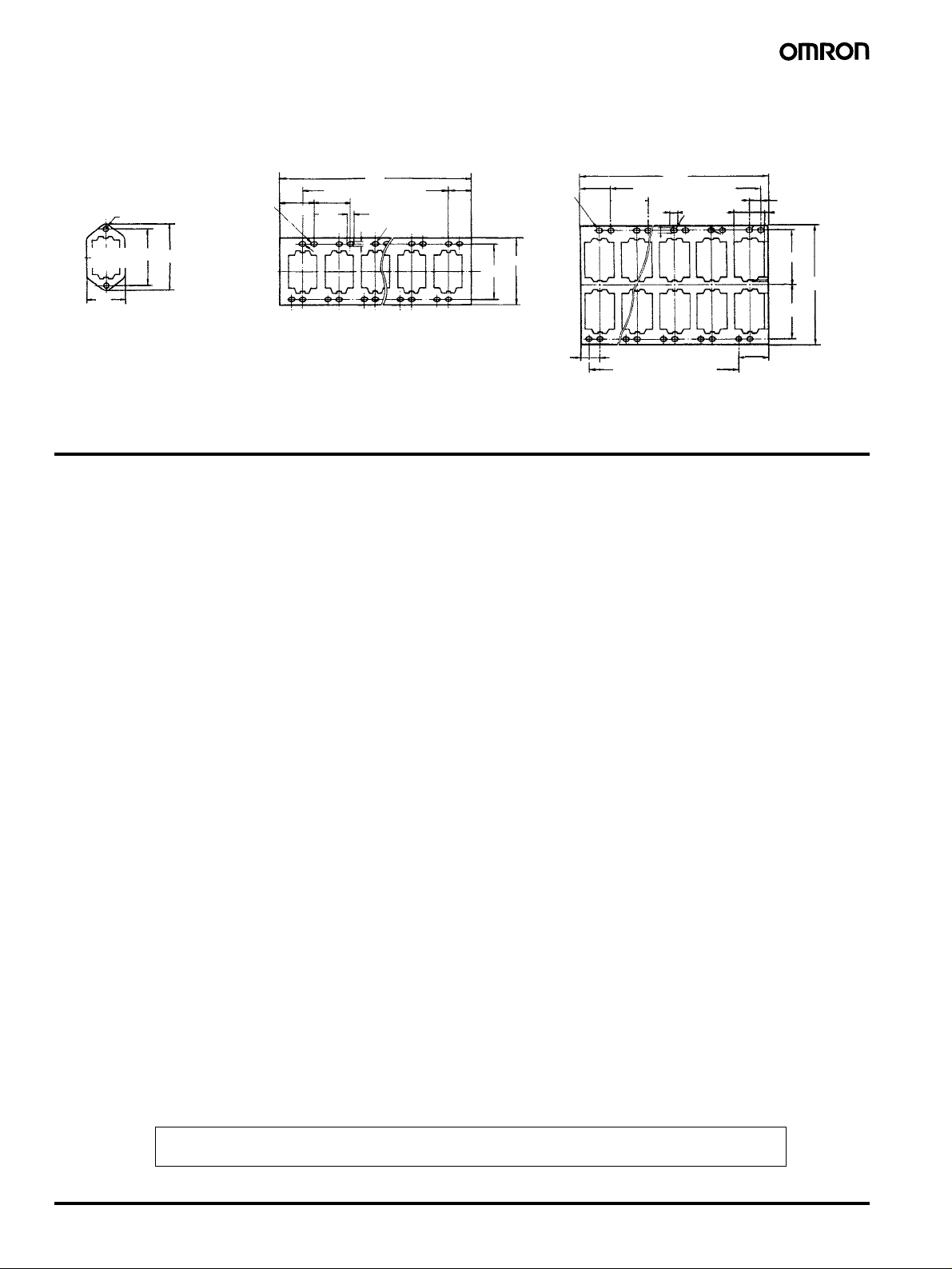
Socket Mounting Plates (t = 1.6 mm)
Use any of these plates when mounting two or more Sockets side-by-side
PYP-1 (for Single Socket Mounting) PYP-18 (for Mounting 18 Sockets) PYP-36 (for Mounting 36 Sockets)
492
27.4 x 17 = 465.8±0.6
4.5
3.4
R1.7
13.1
21.6
Two, 3.4-dia. holes
Square
42±0.1
hole
28
49
72 elliptic holes
492
27.4 x 17 = 465.8±0.6
21.6
27.4
±0.15
Note: PYP-18 and PYP-36 can be cut to a desired length for
mounting less than 18 or 36 Sockets, respectively.
3.4
4.5
R1.7
13.1
72 elliptic holes
49
42±0.1
21.6
27.4
±0.15
13.1
27.4 x 17 = 465.8±0.6
Precautions
Refer to page 11 for general precautions.
A DC coil model with a built-in indicator or built-in diode has coil
polarity. Be sure to wire the terminals correctly, otherwise the diode
may be broken or the operating indicator may not be lit. Furthermore,
as a result of the short-circuiting of the built-in diode, the devices in
the circuit may be damaged.
21.4
39.7±0.2
39.7±0.2
+0.2
−0
86.4
ALL DIMENSIONS SHOWN ARE IN MILLIMETERS.
To convert millimeters into inches, multiply by 0.03937. To convert grams into ounces, multiply by 0.03527.
Cat. No. J014-E1-02
In the interest of product improvement, specifications are subject to change without notice.
126 Power Relay G2A
 Loading...