

Page 1
R88D-GN@
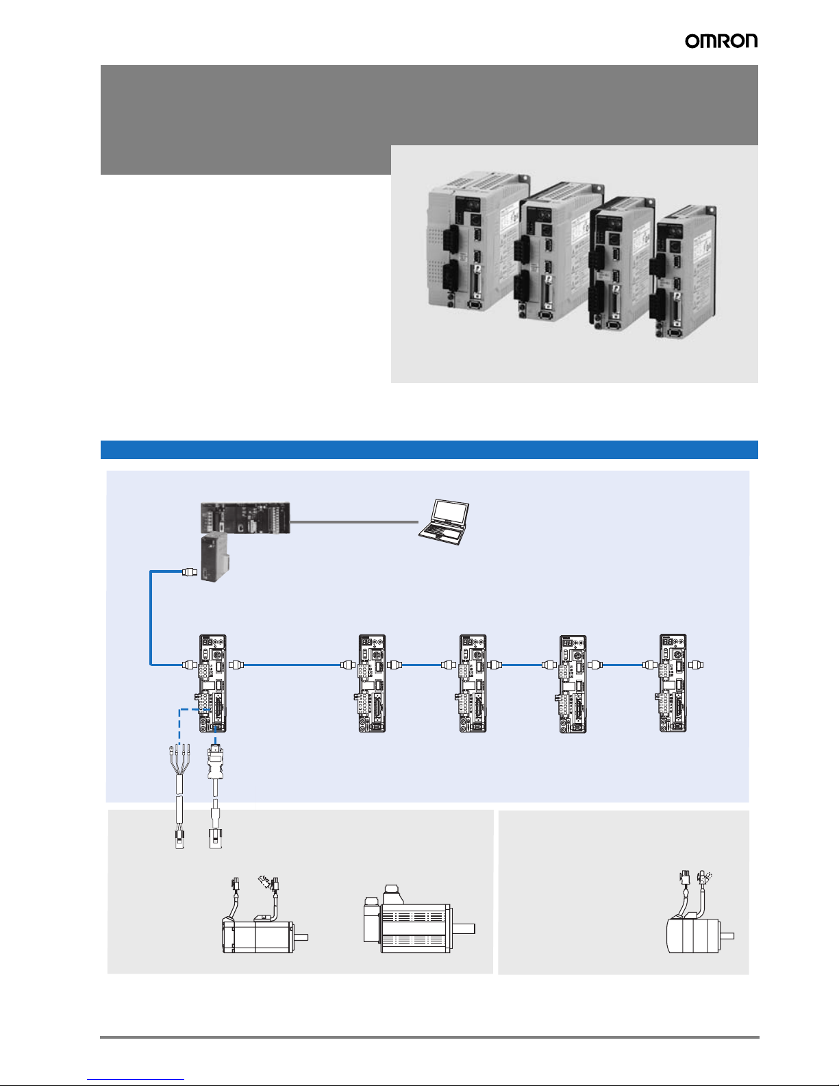
G-Series servo drive
A compact servo drive family for motion
control. Compact size and integrated
MECHATROLINK-II motion bus.
• High-response frequency of 1 kHZ
• Auto-tuning for easy and quick start-up
• Vibration suppression
• Positioning, speed or torque control
• Separate power and control power supply
• Fast and accurate positioning
• Incremental and absolute encoder
Ratings
• 230 VAC Single-phase 100 W to 1.5 kW (8.62 Nm)
System configuration
G-Series MECHATROLINK-II Servo Drive Configuration
Position control unit
CJ1W-NC_71
CS1W-NC_71
Motion Controller
TJ1-MC04/16
CJ1W-MCH72
G-Series
Servo Drive
G-Series Servo Motor
Cylindric servo motors
(50-1500 W)
AC SERVO DRIVER
ADR
0
0
1
1
9
2
2
8
3
3
7
4
6
5
X10
X1
COM
SP
IM
MECHATROLINK-II
G
Encoder cablePower cable
G-Series
Servo Drive
AC SERVO DRIVER
COM
SP
IM
G
ADR
0
0
1
1
9
2
2
8
3
3
7
4
6
5
X10
X1
Personal computer
software: CX-One
G-Series
Servo Drive
AC SERVO DRIVER
ADR
0
1
2
3
X10
COM
SP
IM
G
G-Series
0
1
9
2
8
3
7
4
6
5
X1
Servo Drive
G-Series Servo Motor
Flat servo motors (100-400 W)
G-Series
Servo Drive
AC SERVO DRIVER
ADR
0
0
1
1
9
2
2
8
3
3
7
4
6
5
X10
X1
COM
SP
IM
G
SP
IM
G
AC SERVO DRIVER
ADR
0
0
1
1
9
2
8
3
7
4
6
5
X10
X1
COM
2
3
Terminator
1G-Series servo drive
Page 2
Servo motor supported
Family Voltage Speed Rated torque Capacity Model
Cylindric 50 - 750 W 230 V 3000 min
900 - 1500 W 3.18 Nm 1000 W R88M-G1K030T-@S2 R88D-GN15H-ML2
Flat 100-400 W 3000 min
Servo motor G-Series servo drive
-1
0.16 Nm 50 W R88M-G05030@-@S2 R88D-GN01H-ML2
0.32 Nm 100 W R88M-G10030@-@S2 R88D-GN01H-ML2
0.64 Nm 200 W R88M-G20030@-@S2 R88D-GN02H-ML2
1.3 Nm 400 W R88M-G40030@-@S2 R88D-GN04H-ML2
2.4 Nm 750 W R88M-G75030@-@S2 R88D-GN08H-ML2
4.77 Nm 1500 W R88M-G1K530T-@S2 R88D-GN15H-ML2
-1
2000 min
1000 min
4.8 Nm 1000 W R88M-G1K020T-@S2 R88D-GN10H-ML2
7.15 Nm 1500 W R88M-G1K520T-@S2 R88D-GN15H-ML2
-1
8.62 Nm 900 W R88M-G90010T-@S2 R88D-GN15H-ML2
-1
0.32 Nm 100 W R88M-GP10030@-@S2 R88D-GN01H-ML2
0.64 Nm 200 W R88M-GP20030@-@S2 R88D-GN02H-ML2
1.3 Nm 400 W R88M-GP40030@-@S2 R88D-GN04H-ML2
Type designation
Servo drive
R88D-GN04H-ML2
G-Series servo drive
N: Network type
Capacity
100 W
01
200 W
02
04
400 W
08
750 W
1.0 kW
10
15
1.5 kW
Model
ML2: MECHATROLINK-II communications
Source voltage
H: 230 V
Servo drive specifications
G-Series servo drive
Servo drive type R88D-GN@ 01H-ML2 02H-ML2 04H-ML2 08H-ML2 10H-ML2 15H-ML2
Applicable
servomotor
Max. applicable motor capacity W 100 200 400 750 1000 1500
Continuous output current Arms 1.16 1.6 2.7 4.0 5.9 9.8
Max. output current Arms 3.5 5.3 7.1 14.1 21.2 28.3
Input power Main circuit For single-phase, 200 to 240 VAC +10 to -15%
Supply Control circuit
Control method IGBT-driven PWM method
Feedback Serial encoder (incremental/absolute)
Usage/storage temperature 0 to +55 °C / -20 to 65 °C
Usage/storage humidity 90% RH or less (non-condensing)
Basic specifications
Altitude 1000m or less above sea level
Vibration/shock resistance 5.88 m/s
Conditions
Configuration Base mounted
Approx. weight Kg 0.8 1.1 1.5 1.7
Speed control range 1:5000
Speed
variance
Frequency characteristics 1 kHz
Torque control accuracy (reproducibility) ±3% (at 20% to 100% of rated torque)
Performance
Soft start time setting 0 to 10 s (acceleration time and deceleration time can be set)
MECHATROLINK
Communication
R88M-G@ 05030@/10030@ 20030@ 40030@ 75030@ G1K020T@ 90010T@ / 1K030T@ /
R88M-GP@ 10030@ 20030@ 40030@ - - -
(50/60 Hz)
For single-phase, 200 to 240 VAC + 10 to -15% (50/60 Hz)
2
/ 19.6 m/s
Load variance During 0 to 100% load ±0.01 max. (at rated speed)
Voltage variance 0% at ±10% of rated voltage (at rated speed)
Temperature variance 0 to 50ºC ±0.1% max. (at rated speed)
MECHATROLINK-II commands
(for sequence, motion, data setting/reference, monitor, adjustament and other commands)
2
For single-phase/ three-phase, 200 to 240 VAC +10 to -15%
(50/60 Hz)
1K5@0T@
Command Input
Position/Speed/torque control mode
2 AC servo systems
Page 3
Servo drive type R88D-GN@ 01H-ML2 02H-ML2 04H-ML2 08H-ML2 10H-ML2 15H-ML2
Applicable
servomotor
R88M-G@ 05030@/10030@ 20030@ 40030@ 75030@ G1K020T@ 90010T@ / 1K030T@ /
1K5@0T@
R88M-GP@ 10030@ 20030@ 40030@ - - -
Sequence input signal Emergency stop, 3 external latch signals, forward/reverse torque limit, forward/reverse run prohibit, origin prox-
Sequence output signal It is possible to output three types of signals: positioning completed, speed coincidence, rotation speed detection,
I/O signal
RS-232
communications
Interface Personal computer
Transmission rate From 2400 to 57600 bps
Functions Parameter setting, status display, alarm display (monitor, clear, history), servo drive data tracing function, test
MECHATROLINK
communications
Communications
Communications protocol MECHATROLINK-II
Transmission rate 10 Mbps
Data length 17 bytes and 32 bytes
Functions Parameter setting, status display, alarm display (monitor, clear, history), default values function
imity, 3 general-purpose inputs
servo ready, current limit, speed limit, brake release and warning signal
run/autotuning operations, real time trace, absolute encoder setting, default values function
Automatic load inertia detection Horizontal and vertical axis mode. One parameter rigidity setting.
Dynamic brake (DB) Operates when main power OFF, servo alarm, overtravel or servo OFF
Regenerative processing Built-in regeneration resistor in models from 750 W to 1.5 kW. External regeneration resistor optionally.
Overtravel (OT) prevention function Dynamic brake, disables torque or emergency stop torque during POT and NOT operation
Emergency stop (STOP) Emergency stop input
Encoder divider function Optional division pulses possible
Electronic gearing 0,01<Numerator/Denominator<100
Integrated functions
Internal speed setting function 8 internal speeds
Protective functions Overvoltage, undervoltage, overcurrent, overload, regeneration overload, servo drive overheat
Analog monitor Ouput The actual servomotor speed, command speed, torque and number of accumulated pulses can be measured u-
sing an oscilloscope or other device.
Panel operator Display functions A 2-digit 7-segment LED display shows the servo drive status, alarm codes, parameters, etc.
MECHATROLINK-II communications status LED indicator (COM)
Switches Rotary switch for setting the MECHATROLINK-II node address
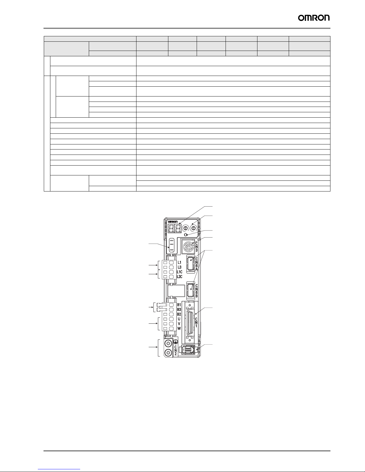
Servo drive part names
Display area
Rotary switches
for ML-II node address
2
3
ML-II comms
status LED indicator
RS-232 comms connector (CN3)
ML-II comms connector
(CN6A, CN6B)
Analog monitor check pins
(SP, IM, G)
Main-circuit power terminals
(L1, L2, L3)
Control-circuit power terminals
(L1C, L2C)
AC SERVO DRIVE
ADR
0
0
1
1
9
2
8
3
7
4
6
5
X10
X1
COM
SP
IM
G
External regenerative resistor
connection terminals (B1, B2, B3)
Servomotor connection terminals
(U, V, W)
Protective ground terminals
G-Series servo drive 3
Control I/O connector (CN1)
Encoder connector (CN2)
Page 4

I/O specifications
Main circuit connector (CNA) specifications
Symbol Name Function
L1 Main circuits power supply input AC power input terminals for the main circuit
L2
L3
L1C Control circuit power supply input AC power input terminals for the control circuit
L2C
Servomotor connector (CNB) specifications
Symbol Name Function
B1 External regeneration resistor connection terminals Up to 400 W: If regenerative energy is high, connect an External
B2
B3
U Servo motor connection terminals Terminals for outputs to the servomotor.
V
W
Frame ground Ground terminal. Ground to 100Ω or less.
Regeneration Resistor between B1 and B2.
From 750 W to 1.5kW: Normally B2 and B3 are connected. If regenerative energy
is high, remove the short-circuit bar between B2 and
B3 and connect an External Regeneration Resistor between
B1 and B2.
I/O signals (CN1) - Input signals
Pin No. Signal name Function
1
2 STOP Emergency Stop Input Input for emergency stop. Emergency stop function factory default: enable.
3
4
5
22 IN1 External general-purpose Input 0
6 IN0 External general-purpose Input 1
23 IN2 External general-purpose Input 2
7
8 Reverse Torque Limit Input
19
20
21 DEC Origin Proximity Input Connect the origin proximity input signal in the origin search operation.
34 BAT
+24VIN
EXT3
EXT2
EXT1
PCL
NCL
POT
NOT
Control power supply input for sequence signals: users must provide the +24 V power supply.
Allowable voltage range: 12 to 24 VDC
External Latch Signals
Forward Torque Limit Input
Forward Run Prohibit Input Forward/ reverse drive rotation overtravel input. Stops servomotor when movable
Reverse Run Prohibit Input
Battery backup input for absolute
encoder
This external signal input latches the current value feedback pulse counter.
Minimal signal width must be 1 ms.
This input is used as external general-purpose input.
This signal input selects the torque limit.
part travels beyond the allowable range of motion.
Connecting pin for the absolute backup battery. Do not connect when a battery is
connected to the servomotor encoder cable.33 BATCOM
I/O signals (CN1) - output signals
Pin No. Signal name Function
15 /ALM
16 ALMCOM
29 OUTM2 General-purpose output.
30 OUTM2COM
31 OUTM3
32 OUTM3COM
36 OUTM1
35 OUTM1COM
The output turns OFF when an alarm is generated in the Servo drive.
The fucntion for this output is selected by changing the parameter:
INP1 (Positioning completed), VCMP (Speed conformity signal), TGON (Servomotor rotation speed detection), READY
(Servo ready), CLIM (Current limit detection), VLIM (Speed limit detection), BKIR (Brake interlock), WARN (Warning
signal)
Encoder connector (CN2)
Pin No. Signal Name Function
1 E5V Encoder power supply + 5 V
2 E0V Encoder power supply ground
3 BAT+ Battery + (used only with absolute encoder)
4 BAT– Battery – (used only with absolute encoder)
5 PS+ Encoder serial signal input (+phase)
6 PS– Encoder serial signal input (-phase)
Shell FG Shield ground
Serial connector (CN3)
Pin No. Signal Name Function
3 TXD RS232 send data
4 GND Ground
5 RXD RS232 receive data
4 AC servo systems
Page 5

Dimensions
Servo drives
R88D-GN01H-ML2 / GN02H-ML2 (200 V, 100 to 200 W)
40
AC SERVO DRIVER
ADR
0
0
1
1
9
2
2
8
3
3
7
4
6
5
X10
X1
COM
SP
IM
G
13270
4
Two , M 4
150
R88D-GN04H-ML2 (200 V, 400 W)
55
AC SERVO DRIVER
ADR
0
0
1
1
9
2
2
8
3
3
7
4
6
5
X10
X1
COM
SP
IM
G
150
150
±0.5
28
6
140
40
13270
±0.5
4
150
±0.5
43
6
Two , M 4
±0.5
140
55
R88D-GN08H-ML2 (200 V, 750 W)
65
AC SERVO DRIVER
ADR
0
0
1
1
9
2
2
8
3
3
7
4
6
5
X10
X1
COM
SP
IM
G
150
G-Series servo drive 5
17270
4
150
±0.5
7.5
50
Two, M4
±0.5
140
65
Page 6

R88D-GN10H-ML2 / GN15H-ML2 (200 V, 1 kW to 1,5 kW )
Filters
85
17270
4
Two, M4
AC SERVO DRIVER
ADR
0
0
1
1
9
2
2
8
3
3
7
4
6
5
X10
X1
COM
SP
IM
G
150
150
7.5
±0.5
70
±0.5
140
85
ØM
drive
mounts
W
M2
D
M1
H
output
flexes
Filter model Rated current Leakage current External dimensions Mount dimensions FIlter Fixing Rated voltage
H W D M1 M2
R88A-FIK102-RE 2.4 A 3.5 mA 190 42 44 180 20 M4 250 VAC single-phase
R88A-FIK104-RE 4.1 A 3.5 mA 190 57 30 180 30 M4
R88A-FIK107-RE 6.6 A 3.5 mA 190 64 35 180 40 M4
R88A-FIK114-RE 14.2 A 3.5 mA 190 86 35 180 60 M4
6 AC servo systems
Page 7

Installation
Single-phase, 230 VAC
L1
L2
L3
N
Thermal switch
Contactor
Noise filter
Single-Phase
200 to 230 VAC
Regeneration
resistor *3
Servo motor
Optical encoder
L1
L3
CNA
L1C
L2C
G-Series
Servo drive
B1
B3
*2
CNB
B2
CNB
CN2
U
V
W
12 to 24 VDC
Emergency Stop
External
Latch 3
External
Latch 2
External
Latch 1
General-purpose
Input 1
Forword Torque
Limit Input
Reverse Torque
Limit Input
Forward run
Prohibit Input
Reverse run
Prohibit Input
Origin Proximity
Input
General-purpose
Input0
General-purpose
Input 2
+24VIN
STOP
EXT3
EXT2
EXT1
IN1
PCL
NCL
POT
NOT
DEC
IN0
IN2
4.7kΩ
1
1kΩ
2
4.7kΩ
1kΩ
3
4.7kΩ
1kΩ
4
4.7kΩ
1kΩ
5
4.7kΩ
1kΩ
6
4.7kΩ
1kΩ
7
4.7kΩ
1kΩ
8
4.7kΩ
1kΩ
19
4.7kΩ
1kΩ
20
4.7kΩ
1kΩ
21
4.7kΩ
1kΩ
22
4.7kΩ
1kΩ
23
CN1
15
/ALM
Alarm Output
16
ALMCOM
OUTM1
36
General-purpose Output 1
35
OUTM1COM
OUTM2
29
General-purpose Output 2
30
OUTM2COM
OUTM3
31
General-purpose Output 3
32
OUTM3COM
34
BAT
33
BATCOM
Backup Battery *1
*1 Connect when using an absolute encoder. If a backup battery is connected, an encoder cable with a battery is not required.
*2 Connect B2-B3 for the models with a built-in regeneration resistor (models from 750 W).
*3 If the amount of regeneration is large, connect an external regeneration resistor to B1-B2. For the models from 750 W, disconnect B2-B3.
G-Series servo drive 7
Shell
FG
Page 8

Ordering information
A
G-Series Cylindrical type Servo Motor
B
G-Series MECHATROLINK-II
Servo Drive
AC SERVO DRIVER
ADR
1
1
0
0
9
2
2
8
3
3
4
7
6
5
X10
X1
3000 rpm (50-750W)
A
G-Series Flat
type Servo Motor
3000 rpm (100-400 W)
3000 rpm (1000-1500 W)
2000 rpm (1000-1500 W)
1000 rpm (900 W)
D
Power cable
C
Encoder cable
K
Filter
L
External
regenerative
resistor
COM
SP
CN3
IM
G
CN6
CN1
H
J
Note: The symbols ABCDE... show the recommended sequence to select the components in a G-Series servo system
Servo motors, power & encoder cables
Note: ACD Refer to the G-Series servo motor chapter for servomotor, motor cables or connectors selection
Servo drives
Specifications
B
1 phase 200 VAC
Control cables (for CN1)
Symbol Name Connect to Model
E
F
G
Computer cable (for CN3)
Symbol Name Model
H
MECHATROLINK-II Motion controllers
Symbol Name Model
I
Servo drive model A Compatible rotary servo motors
Cylindric type Flat type
100 W R88D-GN01H-ML2 R88M-G05030@ R88M-GP10030@
R88M-G10030@
200 W R88D-GN02H-ML2 R88M-G20030@ R88M-GP20030@
400 W R88D-GN04H-ML2 R88M-G40030@ R88M-GP40030@
750 W R88D-GN08H-ML2 R88M-G75030@ -
1.0 kW R88D-GN10H-ML2 R88M-G1K020T@ -
1.5 kW R88D-GN15H-ML2 R88M-G90010T@ -
R88M-G1K030T@ -
R88M-G1K520T@ -
R88M-G1K530T@ -
I/O connector kit Servo drive I/O
Terminal block cable 1 m XW2Z-100J-B33
signals
- R88A-CNU01C
2 m XW2Z-200J-B33
Terminal block - XW2B-20G4
XW2B-20G5
XW2D-20G6
Computer cable RS232 2 m R88A-CCG002P2
Trajexia stand-alone motion controller TJ1-MC04 (4 axes)
TJ1-MC16 (16 axes)
Trajexia-PLC motion controller CJ1W-MCH72
Position Controller Unit for CJ1 PLC CJ1W-NCF71 (16 axes)
CJ1W-NC471 (4 axes)
CJ1W-NC271 (2 axes)
Position Controller Unit for CS1 PLC CS1W-NCF71 (16 axes)
CS1W-NC471 (4 axes)
CS1W-NC271 (2 axes)
Computer software
Specifications Model
Configuration and monitoring software tool for servo drives and
inverters. (CX-drive version 1.70 or higher)
Complete OMRON software package including CX-drive.
(CX-One version 3.10 or higher)
MECHATROLINK-II cables (for CN6)
Symbol Specifications Length Model
J
MECHATROLINK-II
Terminator resistor
MECHATROLINK-II cables 0.5 m JEPMC-W6003-A5-E
Filters
Symbol Applicable
K R88D-GN01H@
servodrive
R88D-GN02H@
R88D-GN04H@ R88A-FIK104-RE 4.1 A 3.5 mA
R88D-GN08H@ R88A-FIK107-RE 6.6 A 3.5 mA
R88D-GN10H@
R88D-GN15H@
External regenerative resistor
Symbol Regenerative resistor unit model Specifications
L
R88A-RR08050S 50 Ω, 80 W
R88A-RR080100S 100 Ω, 80 W
R88A-RR22047S 47 Ω, 220 W
R88A-RR50020S 20 Ω, 500 W
Personal computer:
Sofware CX-One
MECHATROLINK-II cables
E
Servo drive I/O signals
F
Terminal block
G
for Servo drive I/O
signals
- JEPMC-W6022-E
1 m JEPMC-W6003-01-E
3 m JEPMC-W6003-03-E
5 m JEPMC-W6003-05-E
10 m JEPMC-W6003-10-E
20 m JEPMC-W6003-20-E
30 m JEPMC-W6003-30-E
Filter model Rated
R88A-FIK102-RE 2.4 A 3.5 mA 250 VAC
R88A-FIK114-RE 14.2 A 3.5 mA
current
I
MECHATROLINK-II
Motion controllers
Position control unit
CJ1W-NC_71
CS1W-NC_71
Motion controller unit
TJ1-MC04/16
CJ1W-MCH72
CX-drive
CX-One
Leak-
Rated
age
voltage
current
singlephase
ALL DIMENSIONS SHOWN ARE IN MILLIMETERS.
To convert millimeters into inches, multiply by 0.03937. To convert grams into ounces, multiply by 0.03527.
Cat. No. I108E-EN-01A
In the interest of product improvement, specifications are subject to change without notice.
8 AC servo systems
 Loading...