

Page 1
形
FZ-SQ
□□□□
視覚センサ 形FZ用
インテリジェントコンパクトカメラ
取扱説明書
このたびは、本 製 品をお 買い上げいただきまして、まことにありがとうございます。
ご使用に際しては、次の内容をお守りください。
・電気の知識を有する専門家がお取り扱いください。
・
この取扱説明書をよくお読みになり、十分にご理解のうえ、正しくご使用ください。
・この取扱説明書はいつでも参照できるよう大切に保管してください。
2243374-6E
OMRON Corporation
©
●警告表示の意味
正しい取扱いをしなければ、この危険のために、軽傷・中程度の傷
警告
害を負ったり、万一の場合には重傷や死亡に至る恐れがあります。
また、同様に重大な物的損害をもたらす恐れがあります。
●警告表示
このカメラは可視光を放射しており、まれに目に悪影響を及ぼす恐れ
があります。カメラの照射光を直視しないでください。被写体が鏡面
反射体の場合は、反射光が目に入らないようにしてください。
製品を安全に使用するために、以下のことを守ってください。
1.設置環境について
・引火性・爆発性ガスの環境では使用しないでください。
・操作や保守の安全を確保するため、高電圧機器や動力機器から離して設置してください。
2.取付けについて
専用のカメラケーブル、視覚センサ以外には接続しないでください。専用品以外を接続して通電
した場合、機器が故障する恐れがあります。カメラケーブルに無理な応力がかからないように設
置してください。ケーブルが断線し、正常な計測ができなくなる可能性があります。
3.その他
・原子力や、人命に関わる安全装置には使用しないでください。
・本製品を分解、加圧変形、焼却、修理、改造しないでください。
・機器表面は熱くなるため、使用中は触らないでください。
・万一、異常感じたときには、すぐに使用を中止し、電源を切った上で当社支店・営業所までご相
談ください。
・廃棄するときは、産業廃棄物として処理してください。
製品が動作不能、誤動作、または性能・機器への悪影響を防ぐため、以下のことを守ってください。
1.設置・保管場所について
次のような場所には設置・保管しないで下さい。
・周囲温度が定格の範囲を超える場所
・温度変化が急激な場所(結露する場所)
・相対湿度が35〜85%RHの範囲を超える場所
・腐食性ガス、可燃性ガスがある場所
・塵埃、塩分、金属粉がある場所
・振動や衝撃が直接加わる場所
・強い外乱光(レーザ光、アーク溶接光など)があたる場所
・直射日光が当たる場所や暖房器具のそば
・水、油、化学薬品の飛沫がある場所
・強磁界、強電界のある場所
2012
All Rights Reserved.
安全上のご注意
警告
安全上の要点
使用上の注意
2.取付けについて
ケーブルを着脱するときは、必ず視覚センサの電源を切ってください。
取付けにおいて、ネジの締付けは確実に行ってください。
3.光軸・検出範囲について
光軸中心はカメラごとにばらつくことがありますので、取付けるときは必ずコントローラ画面にて
画像の中心を確認してください。
4.ピント調整ボリュームについて
ピント調整ボリュームは0.1N・m以下で回してください。破損する恐れがあります。
5.保守点検について
シンナー、ベンジン、アセトン、灯油類は使用しないでください。カメラ前面のパネルにゴミやホ
コリがついた場合、ブロアブラシ(カメラレンズ用)で吹き飛ばすか、柔らかい布で丁寧にふき取
ってください。呼気で吹き飛ばしたり布で強くこすると、カメラ前面のプレートの破損、キズ、汚
れにより誤検出の原因になります。
6.画素欠陥について
本製品はCMOSセンサ(受光素子)の仕様上、画素欠陥が複数存在することがありますが、製品の
欠陥や故障ではありません。精度の高い検査用途で使用される場合、CCDカメラ(形FZ-S□□□)
をご使用ください。
7.カメラ設置について
高湿度で温度変化が激しい環境下において、前面プレート内部がまれに曇るおそれがあります。
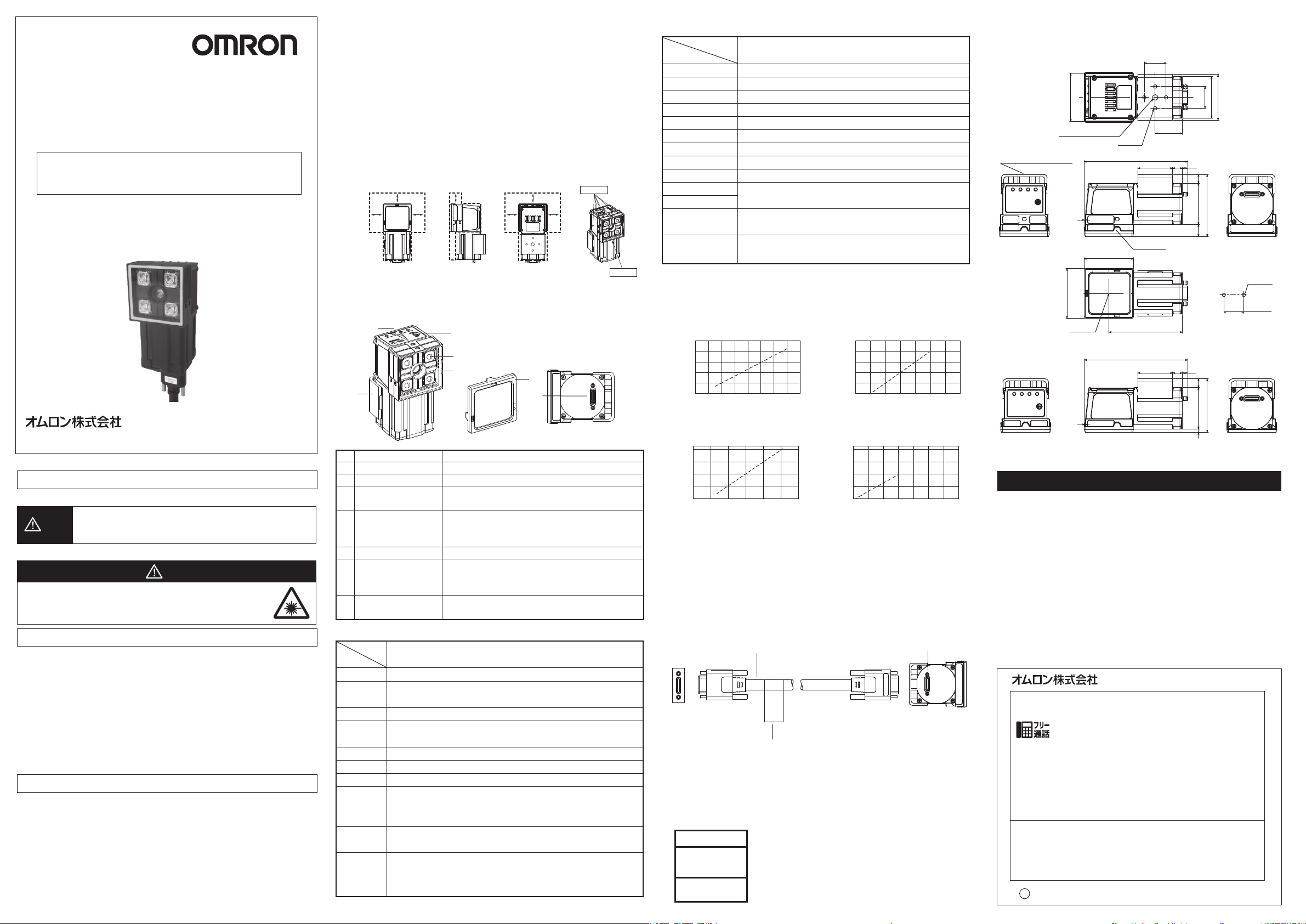
下図に示した点線範囲内に物(専用取り付け金具除く)を設置しないでください。前面プレート内
部が曇る恐れがあります。
25mm 25mm
25mm 25mm
8.取り扱いについて
本体側面に貼付している防水シートを剥がしたり、傷つけたりしないでください。機器内部にゴミ
やホコリ、水滴が入り、故障する恐れがあります。
25mm 25mm
25mm
防 水 シ ート
■各部の名称と機能
(5)
(6)
名称
No.
照明部
(1)
受光部
(2)
カメラケーブル
(3)
接続コネクタ
ピント調整ボリューム
(4)
動作表示灯(POWER)
(5)
取付用金具
(6)
偏光フィルタ
(7)
アタッチメント
(4)
(1)
(2)
説明
照明用のLEDがこの部分に配置されており、光を照射します。
この部分から画像を取り込みます。
視覚センサ形FZと専用カメラケーブル
(形FZ-VS□□)で接続します。
撮影画像のピントを調整するときに使用します。より近いも
のに焦点を合わせたいときはNEAR側に、遠いものに焦点を
合わせたいときはFAR側に回してください。
カメラに電源が供給されているときに緑色に点灯します。
カメラを固定するために使用します。取付用金具はカメラの
前面、右側面、左側面、背面の4方向全てに取り付けること
が出来ます。
照明が対象物に反射しうまく撮影できない場合に装着してく
ださい。
(7)
(3)
■一般仕様
形式
項目
消費電流
耐振動
耐衝撃
周囲温度
周囲湿度
周囲雰囲気
保護構造
材質
重量
付属品
形FZ-SQ010F/SQ100F/SQ050F/SQ100N
1.0A以下
10〜150Hz 片振幅0.35mm(加速度最大50m/s2)
3方向(X/Y/Z) 各8分 10回
150m/s2 6方向(上下・左右・前後) 各3回
動作時:0〜50℃、保存時:−25〜+65℃
(ただし、氷結・結露のないこと)
動作時・保存時:各35〜85%RH(ただし結露しないこと)
腐食性ガスのないこと
IEC60529規格 IP40
カメラ本体:PBT、PC、SUS
取付用金具:PBT、黄銅、ゴムスポンジ(EPDM系)
偏光フィルタアタッチメント:PBT、PC
約150g(FZ-SQ010F/FZ-SQ050F)
約140g(FZ-SQ100F/FZ-SQ100N)
取付用金具(形FQ-XL)×1
偏光フィルタアタッチメント(形FQ-XF1)×1
取扱説明書(本書)×1
防 水 シ ート
■性能仕様
形式
項目
撮像素子
有効画素数
画素サイズ
走査方式
フレームレート
取込ライン数
同期方式
ゲイン
シャッタスピード
視野
形FZ-SQ010F/SQ100F/SQ050F/SQ100N
1/3インチカラーCMOS
752(H)×480(V)
6.0(μm)×6.0(μm)
ノンインターレースモード
60fps
8ライン〜480ラインの範囲
内部同期
0dB〜12dBの範囲
1/250〜1/32258sの範囲
光学図表を参照
設置距離
照明
点灯方式:パルス点灯
照明色:白色
LEDの安全性
リスクグループ2
(IEC62471)
■光学図表(代表例)
・形FZ-SQ010F ・形FZ-SQ100F
設置距離L(mm)
55
45
35
6 8 10 12 14 0 100 200 300
・
形FZ-SQ050F
設置距離L(mm)
210
130
50
注1.視野Vは視野Hの約60%になります。
注2.視野公差±10%以内
視野H(mm)
視野H(mm)
設置距離L(mm)
1000
600
200
・
形FZ-SQ100N
設置距離L(mm)
800
400
0
0 200 400 6000 20 40 60
視野H(mm)
視野H(mm)
■接続
カメラケーブル形FZ-VS□□(別売)で、カメラ裏側のコネクタと視覚センサ形FZシリーズ
のカメラ接続コネクタに接続します。
カメラケーブル
形FZ-VS□□
視覚センサ
FZシリーズ
カメラケーブル
接続コネクタ
カメラ
形FZ-SQ
カメラケーブル
銘板
※カメラケーブルには極性があります。銘板の貼られている側を視覚センサに接続して
ください。
■LEDの安全について
本製品はIEC62471により、リスクグループ2に分類されます。
CAUTION
Possibly hazardous
optical radiation emitted
from this product
Risk Group 2
IEC 62471
■外形寸法図
*取付金具(背面取付)、偏光フィルタアタッチメントありの寸法図を示す。
形FZ-SQ010F/FZ-SQ050F(LED4個タイプ)
44
1/4-20UNC深さ6
取付金具は各側面に取付可能
1
45
46
形FZ-SQ100F/FZ-SQ100N(LED8個タイプ)
1
4-M4
深さ6
(94.8)
ポラライザ
(94.8)
20
20
42
38
(25)
32
67光軸
32
4.89
(57)
11 38 8
取付穴加工寸法
2-φ4.5
20±0.1
締付けトルク:1.2N・m
4.89
8383
(49)
(単位:mm)
ご承諾事項
当社商品は、一般工業製品向けの汎用品として設計製造されています。従いまして、次に
掲げる用途での使用を意図しておらず、お客様が当社商品をこれらの用途に使用される際
には、当社は当社商品に対して一切保証をいたしません。ただし、次に掲げる用途であって
も当社の意図した特別な商品用途の場合や特別の合意がある場合は除きます。
(a)高い安全性が必要とされる用途(例:原子力制御設備、燃焼設備、航空・宇宙設備、鉄
道設備、昇降設備、娯楽設備、医用機器、安全装置、その他生命・身体に危険が及び
うる用途)
(b)高い信頼性が必要な用途(例:ガス・水道・電気等の供給システム、24時間連続運転
システム、決済システムほか権利・財産を取扱う用途など)
(c)厳しい条件または環境での用途(例:屋外に設置する設備、化学的汚染を被る設備、
電磁的妨害を被る設備、振動・衝撃を受ける設備など)
(d)カタログ等に記載のない条件や環境での用途
*(a)から(d)に記載されている他、本カタログ等記載の商品は自動車(二輪車含む。以下同
じ)向けではありません。自動車に搭載する用途には利用しないで下さい。自動車搭載
用商品については当社営業担当者にご相談ください。
*上記は適合用途の条件の一部です。当社のベスト、総合カタログ、データシート等最新版
のカタログ、マニュアルに記載の保証・免責事項の内容をよく読んでご使用ください。
インダストリアルオートメーションビジネスカンパニー
●製品に関するお問い合わせ先
お客様相談室
クイック オムロン
0120-919-066
携帯電話・PHS・IP電話などではご利用いただけませんので、下記の電話番号へおかけください。
電話
055-982-5015
■営業時間:8:00〜21:00 ■営業日:365日
●FAXやWebページでもお問い合わせいただけます。
FAX055-982-5051/www.fa.omron.co.jp
●その他のお問い合わせ
納期・価格・サンプル・仕様書は貴社のお取引先、または貴社
担当オムロン販売員にご相談ください。
オムロン制御機器販売店やオムロン販売拠点は、Webページで
ご案内しています。
v
A
2014年7月
(通話料がかかります)
Page 2
Model
FZ-SQ
□□□□
INTELIGENT COMPACT CAMERA FOR
MODEL FZ VISION SENSOR
INSTRUCTION SHEET
Thank you for selecting OMRON product. This sheet primarily
describes precautions required in installing and operating the
product.
Before operating the product, read the sheet thoroughly to acquire
sufficient knowledge of the product. For your convenience, keep the
sheet at your disposal.
TRACEABILITY INFORMATION:
Representative in EU:
Omron Europe B.V.
Wegalaan 67-69
2132 JD Hoofddorp,
The Netherlands
The following notice applies only to products that carry the CE mark:
Notice:
This is a class A product. In residential areas it may cause radio
interference, in which case the user may be required to take adequate
measures to reduce interference.
OMRON Corporation 2012 All Rights Reserved.
©
Manufacturer:
Omron Corporation,
Shiokoji Horikawa, Shimogyo-ku,
Kyoto 600-8530 JAPAN
・Locations where there is splashing or spraying of water, oil, or chemicals.
・Locations where there is a strong electrical or magnetic field.
2. Handling the Camera
・Be sure to turn off the power before connecting or disconnecting the cables.
・Make sure to tighten all installation screws securely.
3. Optical axis and detection range
There is a certain amount of deviation among cameras in the center of the optical axis. For this
reason, when installing the camera, be sure to check the center of the image and the detection
range in the vision sensor.
4. Focus adjustment knob
Do not turn the focus adjustment knob to higher than 0.1 N·m. This may cause damage.
5. Maintenance and inspection
Do not use thinners, benzene, acetone, or kerosene to clean the camera. If considerable foreign
matter or dust collects on the front panel of the camera, use a blower brush (for camera lens) to blow
off the foreign matter or wipe it gently with a soft cloth. If the surface is damaged because it blew off
with your breath or it wiped hard with a cloth, false detection may result.
6. Defective pixel
It is neither a defect of the product nor a breakdown though two or more defective pixels might be
included in this product by the specification of CMOS image sensor. Use CCD camera FZ-S□□□
when you do the inspection with high accuracy.
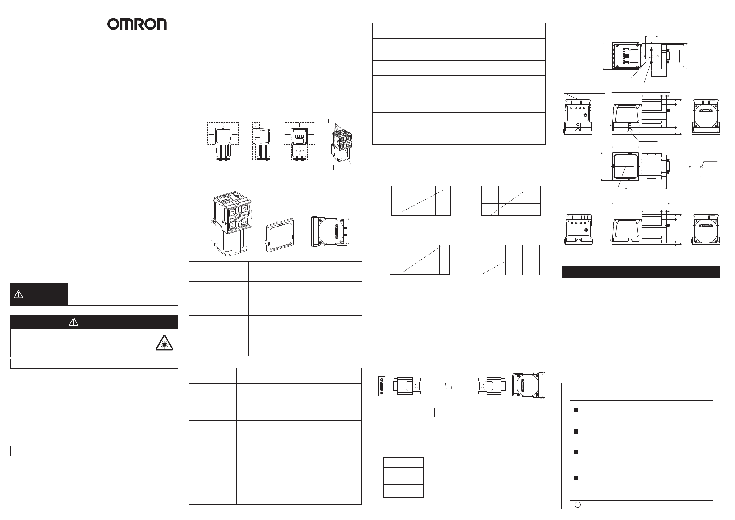
7. Installation of camera
In the environment with high humidity and intense temperature change, the inside of a front plate
might uncommonly become cloudy.
Do not install an object (except for the dedicated mounting bracket) inside the dotted areas shown
on the under figures. Doing so may result in fogging inside the front plate.
25mm 25mm
25mm 25mm
8. Handling
Do not peel off or damage the waterproof sheet attached to the side of the unit. Doing so may result
in dirt, dust or water droplet entering inside the device, causing a failure of the unit.
25mm 25mm
25mm
Waterproofsheet
Waterproofsheet
■ Part Names and Functions
(5)
(6)
(4)
(1)
(2)
(7)
(3)
■ Performance specifications
Item
Picture element
Effective pixels
Pixel size
Scanning method
Frame rate
Number of lines to be read
Synchronization
Gain
Shutter speed
Field of view
Installation distance
Lighting
LED Safety
FZ-SQ010F/SQ050F/SQ100F/SQ100N
1/3-inch color CMOS
752(H)x 480(V)
6.0(μm)x6.0(μm) (Square pixel)
Non-interlace mode
60fps
8 lines to 480 lines
Internal Sync.
0dB to 12dB
1/250 to 1/32258s
Refer to the optical diagram
Lighting method: Pulse
Lighting color: White
Risk Group 2
(IEC62471)
■ Optical diagram (typical example)
・FZ-SQ010F ・FZ-SQ100F
Installation distance (L) (mm)
55
45
35
6 8 10 12 14 0 100 200 300
Horizontal field of view (mm) Horizontal field of view (mm)
・
FZ-SQ050F
Installation distance (L) (mm)
210
Installation distance (L) (mm)
1000
600
200
・
FZ-SQ100N
Installation distance (L) (mm)
800
■ Dimensions
* Dimension diagram with mounting bracket (rear-side attachment) and polarizing
filter attachment is shown.
FZ-SQ010F/FZ-SQ050F(Four LED type)
44
1/4-20UNC Depth 6
The mounting bracket can be
attached to any side
1
45
46
Optical axis
FZ-SQ100F/FZ-SQ100N(Eight LED type)
1
4-M4
Depth 6
(94.8)
(94.8)
Polarizer
67
20
20
42
38
(25)
32
32
4.89
4.89
11 38 8
8383
(57)
Mounting hole
dimensions
(49)
2-4.5Dia.
20±0.1
Tightening
torque: 1.2 N·m
(Unit: mm)
SAFETY PRECAUTIONS
●Keys to Warning Symbols
Indicates a potentially hazardous situation which, if not
WARNING
avoided, could result in death or serious injury.
Additionally, there may be severe property damage.
●Warning Symbols
WARNING
The camera emits visible light which may on rare occasions have a
harmful effect on the eyes. Do not look directly at the light emitted by
the camera. If the light projects onto a reflective surface, prevent the
reflected light from entering a person's eyes.
Precautions for Safe Use
Be sure to respect following items for safety.
1. Installation environment
・Do not use in a location where there is flammable or explosive gas.
・To ensure safe operation and maintenance, install away from high-voltage equipment and power
equipment.
2. Handling the Camera
Do not use unspecified camera cable other than those that specified in this manual with the FZ
controller. Connection with unspecified camera cable may malfunction at the worst case. Do not
put an impossible stress on the camera cable when you set it up. The cable is disconnected,and it
becomes impossible might do a normal measurement.
3. Other Rules
・Do not use in safety circuits for atomic energy or that are critical for human life.
・Do not attempt to disassemble, deform by pressure, incinerate, repair, or modify this product.
・The device surface becomes hot during use. Do not touch.
・If you suspect an error or malfunction,stop using the Controller immediately,turn OFF the power
supply,and consult your OMRON representative.
・When disposing of the product, treat as industrial waste.
Precautions for Correct Use
Observe the following to prevent failure, malfunctioning, and adverse effects on performance and the
device.
1. Installation site
Do not install in the following locations:
・Locations where the ambient temperature exceeds the rated temperature range.
・Locations subject to sudden temperature changes (where condensation will form).
・Locations where the relative humidity is below or above 35 to 85%.
・Locations where there are corrosive or flammable gases.
・Locations where there is dust, salt, or iron powder.
・Locations where the device will be subject to direct vibration or shock.
Locations where there is strong scattered light (laser light, arc welding light, ultraviolet light, etc.)
・
・Locations exposed to direct sunlight or next to a heater.
Name
No.
Lighting
(1)
Camera lens
(2)
Camera cable
(3)
connector
Focus adjustment screw
(4)
(5)
Operation indicators(POWER)
(6)
Mounting Bracket
(7)
Polarizing Filter Attachment
Description
LED for illumination is mounted here, and light is emitted.
Lens with a focus feature.
Used to connect with the Vision sensor FZ with a special
camera cable FZ-VS□□.
Used to adjust the focus of the image. Turn to the NEAR side
when you want to focus it in the vicinity, or turn to the FAR
side when you want to focus it farther.
Lights green when the power is supplied to the camera.
Used to secure the camera in place. The Mounting Bracket
can be attached to the front, left side, right side, or back of
the camera.
Attach the Polarizing Filter Attachment if the image is blurred
by reflections.
■ General specifications
Item
Current consumption
Vibration resistance
Shock resistance
Ambient temperature
Ambient humidity
Ambient environment
Degree of protection
Materials
Weight
Accessories
FZ-SQ010F/SQ050F/SQ100F/SQ100N
Approx. 1A Max.
10 to 150Hz, one-side amplitude 0.35mm
10 times for 8 minutes for each three directions
150m/s2 : 3 times each in 6 directions
Operating: 0 to 50℃ (with no icing nor no condensation)
Strage: -20 to +65℃ (with no icing nor no condensation)
Operating and strage: 35% to 85% (no condensation)
No corrosive gases
IEC60529 IP40
Camera: PBT, PC, SUS
Mounting Bracket: PBT, brass, sponge rubber (EPDM)
Polarizing Filter Attachment: PBT, PC
FZ-SQ010F/FZ-SQ050F: Approx. 150g
FZ-SQ100F/FZ-SQ100N: Approx. 140g
・Mounting Bracket(FQ-XL) (1)
・Polarizing Filter Attachment(FQ-XF1) (1)
・Instruction Manual(this document) (1)
(Max. acceleration 50m/s2)
130
50
Horizontal field of view (mm) Horizontal field of view (mm)
Note 1: Vertical field of view will be approximately 60% of the horizontal field of view.
2: Field of view tolerance: ±10%
400
0
0 200 400 6000 20 40 60
■ Connecting
Using the Camera cable FZ-VS□□(sold separately), connect the connector on the back
of the camera and the connector on Vision sensor FZ series.
Camera cable
FZ-VS□□
Vision sensor
FZ series
Name plate
*The camera cable is polarized, so, make sure that the end bearing a name plate is
connected to the Vision sensor.
■ Safety of LED
The product is considered to be classified as Risk Group 2 by IEC62471
CAUTION
Possibly hazardous
optical radiation emitted
from this product
Risk Group 2
IEC 62471
Camera cable
connector
Camera
FZ-SQ
Suitability for Use
Omron Companies shall not be responsible for conformity with any standards,
codes or regulations which apply to the combination of the Product in the
Buyer’s application or use of the Product. At Buyer’s request, Omron will
provide applicable third party certification documents identifying ratings and
limitations of use which apply to the Product. This information by itself is not
sufficient for a complete determination of the suitability of the Product in
combination with the end product, machine, system, or other application or
use. Buyer shall be solely responsible for determining appropriateness of the
particular Product with respect to Buyer’s application, product or system.
Buyer shall take application responsibility in all cases.
NEVER USE THE PRODUCT FOR AN APPLICATION INVOLVING
SERIOUS RISK TO LIFE OR PROPERTY WITHOUT ENSURING THAT THE
SYSTEM AS A WHOLE HAS BEEN DESIGNED TO ADDRESS THE RISKS,
AND THAT THE OMRON PRODUCT(S) IS PROPERLY RATED AND
INSTALLED FOR THE INTENDED USE WITHIN THE OVERALL
EQUIPMENT OR SYSTEM.
See also Product catalog for Warranty and Limitation of Liability.
OMRON Corporation
Tokyo, JAPAN
Regional Headquarters
OMRON EUROPE B.V.
Sensor Business Unit
Carl-Benz-Str. 4, D-71154 Nufringen, Germany
Tel: (49) 7032-811-0/Fax: (49) 7032-811-199
OMRON ELECTRONICS LLC
One Commerce Drive Schaumburg,
IL 60173-5302 U.S.A.
Tel: (1) 847-843-7900/Fax: (1) 847-843-7787
OMRON ASIA PACIFIC PTE. LTD.
No. 438A Alexandra Road # 05-05/08 (Lobby 2),
Alexandra Technopark,
Singapore 119967
Tel: (65) 6835-3011/Fax: (65) 6835-2711
OMRON (CHINA) CO., LTD.
Room 2211, Bank of China Tower,
200 Yin Cheng Zhong Road,
PuDong New Area, Shanghai, 200120, China
Tel: (86) 21-5037-2222/Fax: (86) 21-5037-2200
r
Sep, 2013
D
Industrial Automation Company
Contact: www.ia.omron.com
 Loading...