

Page 1
形
FZ-SFC/SF/SPC/SP
視覚認識装置 形FZ用 小型デジタルカメラ
取扱説明書
このたび は、本製品をお買い上げいただきまして、まことに ありがとうござ いま す 。
ご使用に際しては、次の内容をお守りください 。
・電気の知識を有する専門家がお取り扱いください。
この取扱説明書をよくお読みになり、十分にご理解のうえ、正しくご使用ください 。
・
・この取扱説明書はいつでも参照できるよう大切に保管してください。
OMRON Corporation All Rights Reserved.
©
安全上のご注意
●
警告表示の意味
●
警告表示
安全を確保する目的で直接的または間接的に人体を検出する用途
に本製品は使用できません。
人体保護用の検出装置として本製品を使用しないでください 。
まれに 失 明 する 恐れがあります。
レンズ単体で直接太陽光を見ないでください 。
レンズをカメラからはずした状 態で、直射日光の当たる場所に
置かないでください 。まれに火災が発生する場合があります 。
正しい取扱いをしなければ、この危険のために、軽傷・中
程度の傷害を負ったり、万一の場合には重傷や死亡に至る
警告
恐れがあります。また、同様に重大な物的損害をもたらす恐
れがあります。
正しい取扱いをしなければ、この危険のために、時に軽傷
・中程度の傷害を負ったり、あるいは物的損害を受ける恐れ
注意
があります。
安全上の要点
製品を安全に使用するために、以下のことを 守ってください 。
1. 設置場所について
次のような場所には設 置しないでください 。
・周囲温度が定格の範囲を超える場所
・温度変化が急激な場所(結露する場所)
・相対湿度が 35 〜 85%RH の範囲を超える場所
・腐食性ガス、可燃性ガスがある場所、塵埃、塩分、金属粉がある場所
・振動や衝撃が直接加わる場所
・強い外乱光(レーザ光 、アーク溶接光など)があたる場 所
*0185689- 2A*
2008
警告
注意
・直射日光があたる場所 や暖 房 器具 のそば
・水・油・化学薬品の飛沫がある場所
・強磁界、強電界がある場所
・高圧機器や動力機器のそば
2.取付けについて
取付けにおいて、ねじ ・レンズ ・ 接 写リングの 締 め 付けは
確実に行ってください 。
カメラアンプのケースは内部回路の 0V ラインに接 続して います 。
ノイズの侵入を防ぐため、以下の内容を守ってください 。
・カメラ本体を接地しないでください 。
・設置の際は、必ず台座、取付ブラケットを使用してください 。
3. その他
・専用のカメラケーブ ル 、コントローラ、ストロボコントローラ以 外 は 使 用しな
いでください 。専用品以外を接続して通電した場合、機器が故障する
恐れがあります。
・カメラアンプ 裏 側 の 拡 張 コネクタを使用しないときに は 、コネクタに
ついているキャップ を 外さな い でください 。
・この製 品を分 解したり、修理、改造しないでください 。
・万一、異常を感じたときに は 、すぐに使 用を 中止し、電源を切った上で
当社支店・営業所までご相談ください 。
・本製品を廃棄するときは 、産業廃棄物として処 理してください 。
使用上の注意
製品が動作不能、誤動作、または 性 能・機器への悪影響を防ぐため、
以下のことを守ってください 。
1.ケーブルについて
・ケーブルを着 脱 す るときは、必ずコントローラ本 体 の 電 源 を切ってください 。
電源が入ったまま着 脱を行うとカメラが壊 れる恐 れ があります 。
2.光軸について
・光軸中心がカメラごとにばらつくことがあります。取付けるときは 必 ず
モニタで映像の中心位置を確認してください 。
3.メンテナンスにつ いて
・CCD 部に大きなゴミや、ホコリが付いた場合は、ブロアブラシ(カメラレン
ズ用)で吹き飛ばしてください 。呼気で吹き飛ばすことは 避 けてください 。
・シンナー、ベンジン、アセトン、灯油類は使用しないでください 。
■付属品
本体、取扱説明書(本書)、取付ブラケット(FZ-SFC/SFのみ)
ねじ4本(M2×4 FZ-SFC/SFのみ)
■仕様
●小型カメラ
▲一般仕様
形式
項目
形状
消費電力
耐振動
耐衝撃
周囲温度
周囲湿度
周囲雰囲気
保護構造
材質・質量
(カメラアンプ )
材質・質量
(カメラヘッド)
形FZ-SFC/SF 形FZ-SPC/SP
フラットタイプ ペンシ ルタイプ
3.4W以下(DC13V 0.26A以下)
10〜150Hz 片振幅0.35mm
2
(加速度最大50m/s
150m/s
)3方向(X/Y/Z) 各8分 10回
2
6方向(上下、左右、前後) 各3回
動作時:0〜+50℃(カメラヘッド)
0〜+45℃(カメラアンプ)
保存時:-25℃〜+65℃
(ただし、氷結・結露のないこと)
動作時・保存時:各35〜85%RH
(ただし、結露しないこと)
腐食性ガスのないこと
IEC60529規格 IP20
カバー:亜鉛メッキ 鋼 板
ケース:アルミダイカスト合金(ADC-12)
台座:ポリカABS
60g(台座込み)
ケース:アルミ合金(A5056)
取付ブラケット:MCナイロン
キャップ:シリコンゴ ム
70g(取付ブラケット込み)
ケース:アルミ合金(A5056)
台座:PC+ガラス繊維
キャップ:シリコンゴ ム
70g(台座込み)
▲性能仕様
項目
形式
撮像素子
転送方式
有効画素数
画素サイズ
走査方式
フレー ムレ ート
取込ライン数
同期方式
映像出力
ゲイン
シャッタースピード
レンズ マウント
形FZ-SFC/SPC 形FZ-SF/SP
1/3インチカラーCCD 1/3インチモノクロC C D
全画素読出し方式インターライン転送型
659(H)×494(V)
7.4(μm)×7.4(μm)
ノンインターレスモード
80fps
12ライン〜480ラインの範囲
内部同期
デジタル 10bit
-6dB〜+24dBの範囲
1/10〜1/50000sの範囲
特殊マウント(M10.5P0.5)
●小型レンズ・接写リング
形式
FZ-LES3
FZ-LES6
項目
焦点距離
絞り
材質
質量
■
カメラアンプの台座取 付け位置を変える場合(全機種)
3mm
F2.0
外郭:アルミ合金(CB156)
約5g 約6g 約4g
FZ-LES16
6mm
レンズ:光学ガラス
16mm
FZ-LES30
30mm −
F3.4
FZ-LESR
−
アルミ合金
(A5056)
カメラアンプの底面についている台座は、取付け位置を
天面、側面に変更することができます。
台座の取付けねじ4個(M2×7)を外し、取付け位置を
変更してください。(取付けねじ推奨締付けトルク:0.32N・m)
台座を天面、側面に取り付けるときは 、取付けねじ3個で
取り付けます 。
■
カメラヘッドの台座取付け位置を変える場合(FZ-SPC/SP)
カメラヘッドの底面についている台座は、取付け位置を
天面、側面に変更することができます。
台座の取付けねじ4個(M1.4×5)を外し、取付け位置を
変更してください。(取付けねじ推奨締付けトルク:0.15N・m)
台座を側面に取り付ける場合、レンズマウント部から
台座までの距離が天面・底面取付け時と変わりますので
ご注意ください。
■
カメラヘッド用 取付ブラケットの使用方法(FZ-SFC/SF)
FZ-SFC/SF付属の取付ブラケットを、下図の向きにカメラ
ヘッドに 取 付 け添 付 のねじ(M2×4 4本)で固定します 。
(取付けねじ推奨締付トルク:0.1N・m)
下図のように取り付けてください。
底面取付け
スペーサ
※カメラヘッドが金属面に接触しないようにするため、
スペーサは11mm以上の長さのものを使用してください。
側面取付け
■カメラヘッドとカメラアンプの 接 続
カメラヘッドのコネクタを、カメラアンプ の 前 面コネクタに
挿し込 ん で 、リングを回してしっかりと固定してください。
形式
シリアル 番 号
形式・シリア ル 番 号を 確 認
接続の際は、カメラヘッドとカメラアンプ の 形 式・シリアル
番号が一致していることをご確認ください。
異なる形式・シリアル番号のカメラヘッドとカメラアンプを
接続した場合、正常に動作しませ ん。
●カメラアンプとカメラケーブル の接 続
①カメラケーブル形FZ-VS□□(別売)で、カメラアンプ
裏側のコネクタとコントローラ形FZシリーズのカメラ接続
コネクタに 接 続します 。
カメラケーブルFZ-VS□□
カメラケ ーブ ル
接続コネクタ
銘板
※カメラケーブル形FZ-VS、FZ-VSL、FZ-VSBには
極性があります 。
銘板の貼られている側をコントローラに接続してください 。
拡張コネクタ
カメラアンプ
FZ-SFC/SF/SPC/SP
■レンズ・接写リングの使用方法(全機種)
①下図のようにレンズを取付け、カメラマウントの奥まで
ねじ込んでください。狭視野・近距離で使用したい
場合は、光学図表を参照の上カメラヘッドとレンズ の
間に接写リングを入 れ てください。
②画像のピントが合う位置にレンズ・接写リングを緩め、
レンズ固 定リング でしっかりと固 定してください。
③絞り調整用つまみで画像の明るさを調整した後、
つまみを回して仮留めし、反対側の固定用ねじで
しっかりと固 定してください。
絞り調 整 用つまみ
絞り固定用ねじ
絞り調 整 用つまみ
※レンズ繰り出し寸法は上記の範囲内でお使いください。
範 囲 外の寸 法 で 使 用されると、使用環境によってはレンズ・接
写リングが外 れ る恐 れ があります 。
レンズ 繰 り出し寸法
(0.7mm〜2.7mm)
レンズ 固 定リング
レンズ 繰 り出し寸 法
(0mm〜2.0mm)
レンズ 固 定リング絞り固定用ねじ
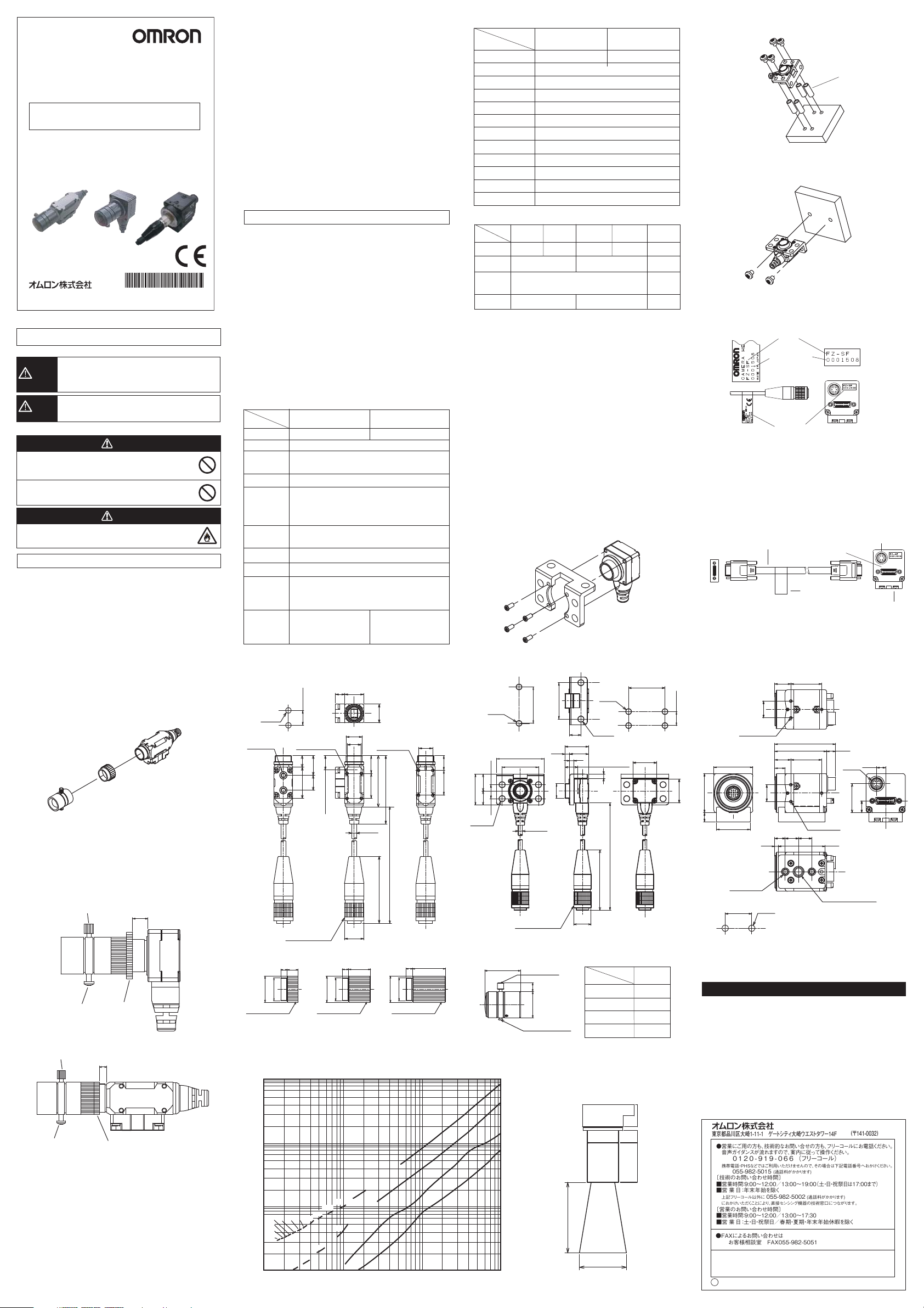
■外形寸法
●カメラヘッド(FZ-SPC/SP)
9.5±0.1
2-φ4.5
取付穴加工寸法
16ピン丸形コネクタ
35
M10.5
8-M1.7深さ1.5
7.520
12.7
9.6
接写リング 1 0 mm 接 写リング15mm
2-M3深さ4
φ1 2
接写リング 5 m m
12
6
12
M10.5
9
4-M1.7深さ1.5
9.2(CCD面より)
φ1 2
M10.5
11.5
44
33
16
φ3
3000
43
φ1 2. 5
310 3 15
φ1 2
(単位:mm)
M10.5
(単位:mm)
■光学図表
次の表を参考にして、レンズと接 写リングを 選 ん でください。
WD(mm)
10000
1000
t5
t25
t10
t15
t20
t5
t10
10 100 1000
100
10
t30t40t45
t35
t50
t55
t60
t15
t20
1
●カメラヘッド(FZ-SFC/SF)
26±0.1
8
16.9
13.5
φ12.5
3
4-M4
2-φ4.3
9.2(CCD面より)
3
3000
43
取付穴加工寸法2
17
(単位:mm)
2-M4
22
4 -φ4. 3
取付穴加工寸法1
4.5
12
10
5.5
34
26
16ピン丸形コネクタ
9
9.5
16
26
26±0.1
3.4
M10.5
φ3
●カメラアンプ(全形式)
10±0.1
17
28
6.5
取付穴加工寸法
3-M2深さ3.0
28
24
2-M4深さ5.5
19±0.1
12
12
2.5
2 -φ4. 5
11.5
11.5
7.5
7.5
43.5
37
9.5 9.5
22
22
3-M2深さ3.0
(6.5)
(6.5)
(φ8.8)
(20.7)
(8.5)
33.5
1/420UNC深さ5.5
(単位:mm)
●小型レンズ(FZ-LES□□別売)●接写リング(FZ-LESR別売)
L
絞り調 節つまみ
4
φ1 2
絞り固定ネジ(M1.4)
(単位:mm)
FZ-LES30
FZ-LES16
t0
t0
t0
t0
FZ-LES6
FZ-LES3
WD
Y視野(㎜)
寸法
形式
FZ-LES3
FZ-LES6
FZ-LES16
FZ-LES30
Y視野
L
16.4
19.7
23.1
25.5
カメラヘッド
接写リング
レンズ
ご使用に際してのご承諾事項
①安全を確保する目的で直接的または間接的に人体を検出する用途に、本製品を使用し
ないでください 。同用途には、当社センサカタログに掲載している安全センサをご使用く
ださい 。
②下記用途に使用される場合、当社営業担当者までご相談のうえ仕様書などによりご確
認いただくとともに 、定格・性能に対し余裕を持った使い方や、万一故障があっても危険
を最小にする安全回路などの安全対策を講じてください 。
a)屋外の用途、潜在的な化学的汚染あるいは電気的妨害を被る用途
またはカタログ 、取扱説明書等に記載のない条件や環境での使用
b)原子力制御設備、焼却設備、鉄道・航空・車両設備、医用機械、娯楽機械、
安全装置、および行政機関や個別業界の規制に従う設備
c)人命や財産に危険が及びうるシス テ ム・機械・装置
d)ガス、水道、電気の供給システムや24時間連続運転システムなどの
高い信頼性が必要な設備
e)その他、上記a)〜d)に準ずる、高度な安全性が必要とされ る用 途
*上記は適合用途の条件の一部です。当社のベスト、総合カタログ・データシート等最新版
のカタログ、マニュアルに 記載 の保 証・免責事項の内容をよく読ん でご 使 用ください 。
東京都品川区大崎1-11-1 ゲートシティ大崎ウエストタワー14F
●営業にご用の方も、技術的なお問い合せの方も、フリーコールにお電話くださ い 。
音声ガイダンスが流れますので、案内に従って操作ください 。
0120-919-066(フリーコール)
携帯電話・PHSなどではご利用いただけませんので、その場合は下記電話番号へおかけください 。
055-982-5015
〔技術のお問い合わせ時間〕
■
営業時間:9:00〜12:00/13:00〜19:00(土・日・祝祭日は17:00まで)
■営 業 日:年末年始を除く
上記フリーコール以外に
におかけいただくことによ り、直接センシング機器の技術窓口につながります 。
〔営業のお問い合わせ時間〕
■
営業時間:9:00〜12:00/13:00〜17:30
■営 業 日:土・日・祝祭日/春期・夏期・年末年始休暇を除く
●FAXによるお問い合わせは
お客様相談室 FAX055-982-5051
●その他のお問い合せ先
納期・価格・修理・サンプ ル・承認図は貴社のお取引先、
または貴社担当オムロン営業員にご相談ください 。
R
営業統轄事業部
(通話料がかかります)
055-982-5002
(通話料がかかります)
(
〒141-0032
)
Page 2
Model
FZ-SFC/SF/SPC/SP
SMALL DIGITAL CAMERA FOR
MODEL FZ VISUAL INSPECTION SYSTEM
INSTRUCTION SHEET
Thank you for selecting OMRON product. This sheet primarily describes precautions required in installing and
operating the product.
Before operating the product, read the sheet thoroughly to
acquire sufficient kno wledge of the product. For your convenience, keep the sheet at your disposal.
TRACEABILITY INFORMATION:
Representative in EU
Omron Europe B.V.
Wegalaan 67-69
2132 JD Hoofddorp
The Netherlands
NOTICE:
This product meets CISPR11 class A. The intended use of this product
is in an industrial environment only.
OMRON Corporation All Rights Reserved.
©
PRECAUTIONS ON SAFETY
Meaning of Alert Symbols
WARNING
CAUTION
Alert statements
This product is not designed or rated for ensuring
safety of persons. Do not use it for such purposes.
It is likely to lose one's sight unusually.Please do not
look at the sun light directly with the lens unit.
Please do not put it on the place where direct sunshine
tries the lens with the lens removed from the camera.
A fire might occur unusually.
PRECAUTIONS FOR SAFE USE
Be sure to respect following items for safety.
(1) Installation Site
Do not install the product in locations subjected to the following
conditions:
・ Ambient temperature outside the rating
・ Rapid temperature fluctuations (causing condensation)
・ Relative humidity outside the range of 35 to 85%
・ Presence of corrosive or flammable gases
・ Presence of dust, salt, or metallic particles
・ Direct vibration or shock
・ Reflection of intense light (such as other laser beams or electric
arc-welding machines)
・ Direct sunlight or near heaters
Manufacturer
Omron Corporation,
Sensing Devices & Components Div.H.Q.,
Application Sensors Division
Shiokoji Horikawa, Shimogyo-ku,
Kyoto, 600-8530 JAPAN
2008
Indicates a potentially hazardous situation which, if
not avoided, will result in minor or moderate injury,
or may result in serious injury or death. Additionally
there may be significant property damage.
Indicates a potentially hazardous situation which, if
not avoided, may result in minor or moderate injury
or in property damage.
WARNING
CAUTION
・ Water, oil, or chemical fumes or spray
・ Strong magnetic or electric field
Near high-voltage eqipment or power eqipment
・
(2) Handling the Camera
In the installation, tighten the screw, the lens, and the
photograph ring surely.
The Camera amplifier case is connected to the 0V line in the internal circuits.
Observe the following precautions to prevent noise interference.
・ Do not ground the Camera.
・ Please use the plinth and the mounting bracket when you set it up.
(3) Others
・
Do not use unspecified camera cable and a strobe controller
other than those that specified in this manual with the FZ
controller. Connection with unspecified camera cable and/or
strobe controller may malfunction at the worst case.
・ If you do not use the enhancing connector on the back of the camera
amplifier, do not remove the cap that is attached to the connector.
・ Do not attempt to dismantle, repair, or modify the main body.
・ If you suspect an error or malfunction, stop using the Controller
immediately, turn OFF the power supply, and consult your
OMRON representative.
・ Dispose of FZ-SC5M/S5M components as industrial waste.
PRECAUTIONS FOR CORRECT USE
Please observe the following precautions to prevent failure to operate,
malfunction, or undesirable effect.
(1) Connecting Cables
・ Be sure to turn off the power before connecting or
disconnecting the cables.The camera might break when the
power supply detaches it while turned on.
(2) Optical axis of the Camera.
・
The center of the optical axis varies with the camera used.
Therefore, when installing the camera, always check the center
of the image displayed on the monitor.
(3) Maintenance
・ If large dust particles adhere to the CCD, use a blowerbrush
(used to clean camera lenses) to blow them off. Do not blow
the dust particles with your mouth.
・ Do not use thinners, benzene, acetone, or kerosene to clean Camera.
■Accessories
Main unit, instruction sheet(this manual), mounting bracket
(only FZ-SFC/SF), four screws(M2×4 only FZ-SFC/SF)
■Specifications
Small camera
▲General specifications
Item
shape
Power
consumption
Vibration
resistance
Shock
resistance
Ambient
Temperature
Ambient
humidity
Ambient
environment
Degree of
protection
Materials/Weight
(Camera amplifier)
Materials/Weight
(Camera head)
Flat type
3.4W max.(13V DC,0.26A max.)
10 to 150Hz: half-amplitude: 0.35mm:
(maximum acceleration: 50m/s
10 times each in X, Y, and Z directions for 8 min
Shock resistance 150m/s
3 times each in 6 directions
(up/down, left/right, forward/backward)
Operating: 0 to 50 ℃(camerahead)
(with no icing nor condensation)
Operating: 0 to 45 ℃(camera amplifier)
(with no icing nor condensation)
Storage: -25 to 65 ℃
(with no icing nor condensation)
Operating and storage: 35% to 85%
(with no condensation)
No corrosive gases
IEC60529 IP20 (in-panel)
Cover: Galvanized sheet iron
Case: Aluminum die cast alloy (ADC-12)
Base: polycarbonate ABS
Case: Aluminum alloy (A5056)
Bracket: MC nylon
Cap: Silicon rubber
70g (including bracket)
60g (including base)
FZ-SPC/SPFZ-SFC/SF
Pencil type
2
),
2
;
Case: Aluminum alloy (A5056)
Base: PC / Glass fiber
Cap: Silicon rubber
70g (including base)
▲
Performance specifications
Item
Picture element
Transmission mode
Effective pixels
Pixel size
Scanning method
Frame rate
Number of lines to be
read
Synchronization
Video output
Gain
Shutter speed
Lens mounting
FZ-SFC/SPC FZ-SF/SP
1/3-inch color CCD
1/3-inch monochrome CCD
Interline reading all pixels
659(H)×494(V)
7.4(µm)×7.4(µm)(Square pixel)
Non-interlace mode
80fps
12 lines to 480 lines
Internal Sync.
Digital (10 bits)
-6dB to + 24dB
1/10 to 1/50000s
Special mount (M10.5 P0.5)
Small lens / Photograph ring
Item
Focal length
Aperture
Materials
Weight
FZ-LES3
FZ-LES6
FZ-LES16
FZ-LES30
3mm
6mm
16mm
30mm
F2.0
F3.4
Lens: Optical glass
Outline: Aluminum alloy(CB156)
Approx. 5g Approx. 6g Approx. 4g
■Changing the base mount position of
camera amplifier(All models)
The camera base attached to the bottom of the camera
amplifier can also be attached to the another side of the
camera
amplifier.Remove the four screws(M2×7) from the
base and re-attach the base to the another side of the camera
amplifier.(Recommended screw tightening torque:0.32N・m)
When the plinth is attached in the top side and the side,
mount it by three mounting screws.
■Changing the base mount position of
camera head(FZ-SPC/SP)
The camera base attached to the bottom of the camera
head can also be attached to the another side of the camera
head.Remove the four screws(M1.4×5) from the base and
re-attach the base to the another side of the camera
head.(Recommended screw tightening torque:0.15N・m)
The distance from the lens mount to plinth must note the
change from the installation of top side or the bottom
when you install it in side respect of plinth.
■
Use of mounting bracket for camera head (FZ-SFC/SF)
The mounting bracket of the FZ-SFC/SF attachment is fixed
by screw(M2×4 Four) that is attached to camera head in the
direction of figure below.
(Recommended screw tightening torque:0.1N・m)
FZ-LESR
−
−
Aluminum alloy
(A5056)
Please mount it as shown in the figure below.
Bottom installation
Spacer
*
Spacer must use the length of 11mm or more to prevent
camera head from coming in contact with metallic side.
Side installation
■
Connection of camera head and camera amplifier
Please do insert the front connector of camera amplifier
with connector of camera head, turn the ring, and fix firmly.
Model
Serial number
The model and the serial number are confirmed.
Confirm the model and serial number of the camera
amplifier and camera head is same, when connecting it.
When the camera head and the camera amplifier of a
different model and the serial number are connected, it
doesn't operate normally.
Connection of camera amplifier and camera cable
(1) Using the Camera cable FZ-VS□□(sold separately),
connect the connector on the back of the camera amplifier
and the camera connector on Controller FZseries.
Camera cable
FZ-VS□□
Name plate
Camera cable
connector
Enhancing connector
amplifier
Camera
FZ-SFC/SF/SPC/SP
*The camera cable (FZ-VS,FZ-VSL,FZ-VSB) is polarized, so,
make sure that the end bearing a name plate is connected to the
Controller.
■
Use of lens and photograph ring
(All models)
(1) Mount of lens as shown in the figure below, and screw in
to the inner of the camera mount. Put the photograph ring
between the camera head and the lens after referring to an
optical diagram when you want to use it in the narrowness
view and the short distance.
(2) Loosen the lens and the photographing ring to the position
in which the focus of the image is suitable, and fix firmly
with the lens fixation ring.
(3) Rotate a knob after adjusting the brightness of the image
by the disphragm adjustment knob, detain temporarily,
and fix firmly with the fixed screw of the other side.
Diaphragm adjustment knob
Diaphragm look screw
Lens fixation ring
Diaphragm
adjustment knob
Diaphragm look screw
※Please use the draw out dimension of lens within the
above-mentioned range.The lens and the photographing
ring might come off according to the environment of use
when used by the dimension outside the range.
Drawing out dimension of lens
(0.7mm to 2.7mm)
Drawing out dimension of lens
(0mm to 2.0mm)
Lens fixation ring
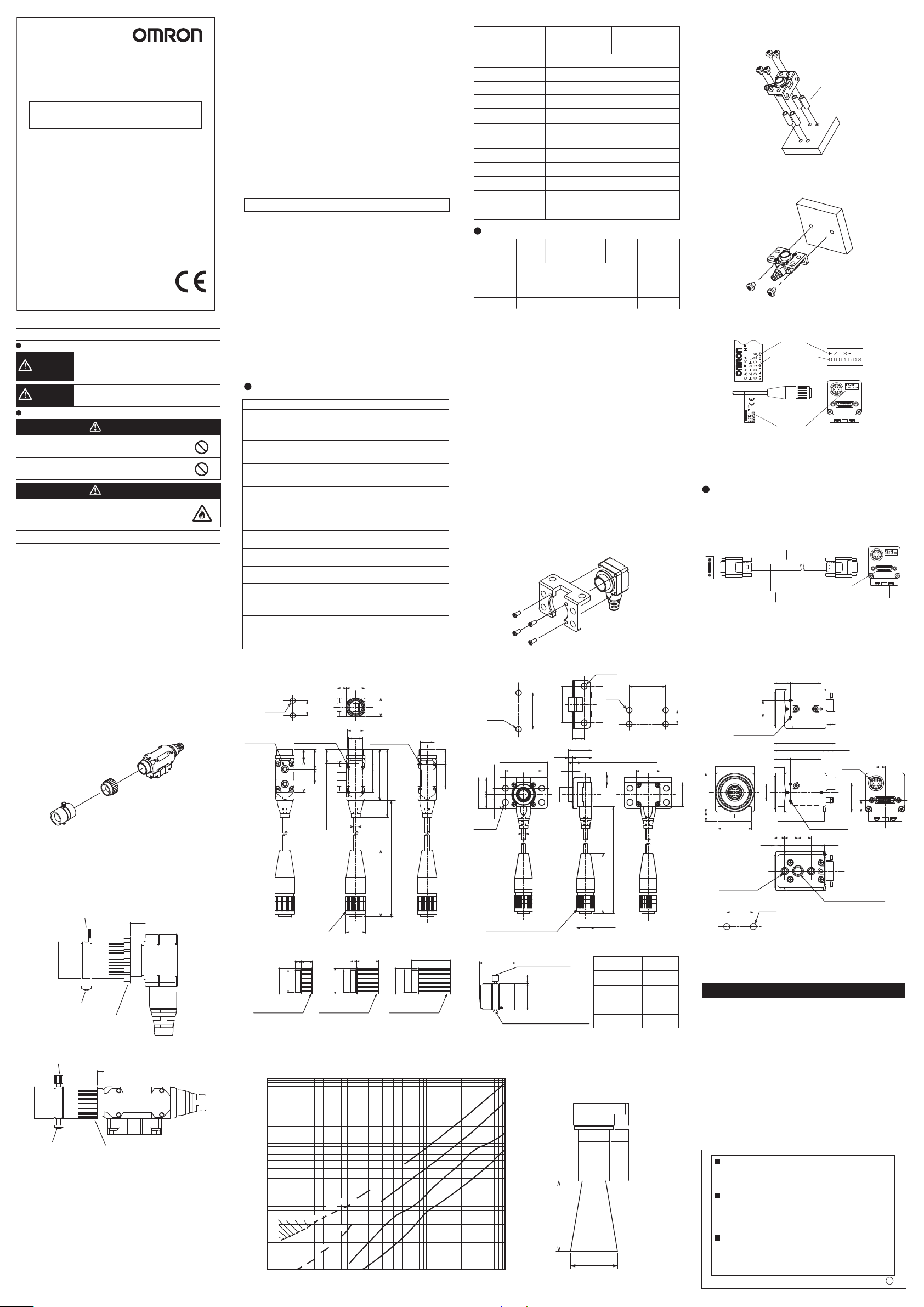
■Dimensions
●Camera head(FZ-SPC/SP)
9.5±0.1
2-4.5Dia.
MOUNTING SCREW HOLES
2-M3 DEPTH 4
16PIN ROUND CONNECTOR
8-M1.7 DEPTH 1.5
7.520
12.7
9.6
●Photograph ring(FZ-LESR optional)
35
M10.5
12Dia.
PHOTOGRAPH RING
5mm
Optical diagram
■
PHOTOGRAPH RING
10mm
Select the lens and the photograph ring referring to the table below.
WD(mm)
10000
1000
100
t50
t55
t60
10
1
t20
t30t40t45
t35
t25
t10
t15
t20
12
6
12
M10.5
9
4-M1.7 DEPTH 1.5
9.2(FROM CCD SURFACE)
12Dia.
11.5
44
33
16
3Dia.
43
12.5Dia.
310 3 15
M10.5
3000
PHOTOGRAPH RING
15mm
(Unit:mm)
M10.5
12Dia.
9
9.5
16
(Unit:mm)
t5
t10
t15
t5
10 100 1000
●Camera head(FZ-SFC/SF)
2-M4
MOUNTING SCREW HOLES1
4.5
12
22
10
5.5
4-4.3Dia.
16PIN ROUND CONNECTOR
26±0.1
34
26
3Dia.
●Small lens(FZ-LES□□optional)
DIAPHRAGM
L
ADJUSTMENT KNOB
4
12Dia.
DIAPHRAGM LOOK SCREW(M1.4)
(Unit:mm)
FZ-LES30
FZ-LES16
t0
t0
t0
t0
FZ-LES6
FZ-LES3
WD
Y view(mm)
3.4
M10.5
2-4.3Dia.
26±0.1
26
16.9
3
4-M4
8
13.5
MOUNTING SCREW HOLES2
9.2(FROM CCD SURFACE)
3
3000
43
12.5Dia.
Model
FZ-LES3
FZ-LES6
FZ-LES16
FZ-LES30
17
(Unit:mm)
L
16.4
19.7
23.1
25.5
Camera head
Photograph
ring
Lens
Y view
●Camera amplifier(All models)
22
11.5
10±0.1
28
17
6.5
MOUNTING SCREW HOLES
2-M4 DEPTH 5.5
3-M2 DEPTH 3.0
28
24
19±0.1
12
12
2.5
2-4.5Dia.
43.5
37
11.5
22
7.5
9.5 9.5
7.5
(6.5)
(8.8Dia.)
3-M2 DEPTH 3.0
33.5
1/4”-20UNC DEPTH 5.5
Suitability for Use
THE PRODUCTS CONTAINED IN THIS SHEET ARE NOT SAFETY RATED.
THEY ARE NOT DESIGNED OR RATED FOR ENSURING SAFETY OF
PERSONS, AND SHOULD NOT BE RELIED UPON AS A SAFETY
COMPONENT OR PROTECTIVE DEVICE FOR SUCH PURPOSES.
Please refer to separate catalogs for OMRON's safety rated products.
OMRON shall not be responsible for conformity with any standards, codes, or
regulations that apply to the combination of the products in the customer's
application or use of the product.
Take all necessary steps to determine the suitability of the product for the
systems, machines, and equipment with which it will be used.
Know and observe all prohibitions of use applicable to this product.
NEVER USE THE PRODUCTS FOR AN APPLICATION INVOLVING
SERIOUS RISK TO LIFE OR PROPERTY WITHOUT ENSURING THAT THE
SYSTEM AS A WHOLE HAS BEEN DESIGNED TO ADDRESS THE RISKS,
AND THAT THE OMRON PRODUCT IS PROPERLY RATED AND
INSTALLED FOR THE INTENDED USE WITHIN THE OVERALL
EQUIPMENT OR SYSTEM.
See also Product catalog for Warranty and Limitation of Liability.
EUROPE
OMRON EUROPE B.V. Sensor Business Unit
Carl-Benz Str.4, D-71154 Nufringen Germany
Phone:49-7032-811-0 Fax: 49-7032-811-199
NORTH AMERICA
OMRON ELECTRONICS LLC
One Commerce Drive Schaumburg,IL 60173-5302 U.S.A
Phone:1-847-843-7900 Telephone Consultation
1-800-55-OMRON Fax : 1-847-843-7787
ASIA-PACIFIC
OMRON ASIA PACIFIC PTE LTD
83 Clemenceau Avenue,#11-01 UE Square,Singapore 239920
Phone : 65-6-835-3011 /Fax :65-6-835-2711
OMRON Corporation
(6.5)
(20.7)
(8.5)
(Unit:mm)
n
 Loading...