

Page 1
形
FZ-SHC/SH
視覚認識装置形FZ用高速デジタルカメラ
取扱説明書
このたび は、本製品をお買い上げいただきまして、まことにありがとうござ い ま す 。
ご使用に際しては、次の内容をお守りください 。
・電気の知識を有する専門家がお取り扱いください 。
この取扱説明書をよくお読みになり、十分にご理解のうえ、正しくご使用ください 。
・
・この取扱説明書はいつでも参照できるよう大切に保管してください 。
*2135165- 7A*
OMRON Corporation All Rights Reserved.
©
安全上のご注意
●警告表示の意味
正しい 取 扱 いをしなければ、この危険のために、
軽傷・中程度の傷害を負ったり、万一の場合に
警告
は重傷や死亡に至る恐れがあります。また、同様
に重大な物的損害をもたらす恐 れが あります 。
正しい 取 扱 いをしなければ、この危険のために、
時に軽傷・中程度の傷害を負ったり、あるいは物
注意
的損害を受ける恐れがあります 。
●警告表示
安全を確保する目的で直接的または間接的に人体を検
出する用途に本製品は使用できません。人体保護用の
検出装置として本製品を使用しないでください 。
製品を安全に使用するために、以下のことを守ってください 。
1. 設置・保管場所について
次のような場所には設置・保管しないでください 。
・周囲温度が定格の範囲を超える場所
・温度変化が急激な場所(結露する場所)
・相対湿度が 35 〜 85%RH の範囲を超える場所
・腐食性ガス、可燃性ガスがある場所、塵埃、塩分、金属粉があ
る場所
・振動や衝撃が直接加わる場所
・強い外乱光(レーザ 光 、アーク溶接光など)があたる場所
・直射日光があたる場所や暖房器具のそば
2010
警告
安全上の要点
・水・油・化学薬品の飛沫がある場所
・強磁界、強電界がある場所
・高圧機器や動力機器のそば
2. 取付けについて
取付けにおいて、ねじの締め付けは確実に行ってください 。カメラの
ケースは 内 部 回 路 の 0V ラインに 接 続しています 。ノイズの侵 入を
防ぐため、以下の内容を守ってください 。
・カメラ本体を接地しないでください 。
・設置の際は、必ず台座を使用してください 。
3. その他
・専用のカメラケーブ ル 、コントローラ、ストロボコントローラ以 外 は 使
用しない でください 。専用品以外を接続して通電した場合、機器
が故障する恐れがあります 。
・カメラ裏 側の拡 張コネクタを使用しないときには 、 コネクタにつ い
ているキャップを 外さない でください 。
・この製 品を分 解したり、修理、改造しないでください 。
・万一、異常を感じたときに は 、すぐに使 用を中 止し、電源を切っ
た上で当社支店・営業所までご相談ください 。
・本製品を廃棄するときは、産業廃棄物として処 理してください 。
使用上の注意
製品が動作不能、誤動作、または 性 能・機器への悪影響を防ぐた
め、以下のことを守ってください 。
1. ケーブルについて
・ケーブルを着 脱するときは、必ずコントローラ本体の電源を切って
ください 。
2. 光軸について
・ 光 軸 中 心 がカメラごとに ばらつくことがあります 。取付けるときは 必
ずモニタで映像の中心位置を確認してください 。
3.メンテナンスについて
・CCD 部に大きなゴミや、ホコリが付いた場合は、ブロアブラシ(カメ
ラレンズ 用 ) で 吹き 飛 ばしてください 。呼 気で吹き飛 ばすことは 避
けてください 。
・シンナー、ベンジン、アセトン、灯油類は使用しないでください 。
4. 撮像素子について
・計測 条件や感度により画像中心に縦 方向の線が入ることがあり
ますが 、撮像素子の構造によるもの で 故 障 で はありません。
■仕様
●一般仕様
形式
項目
消費電力
耐振動
耐衝撃
周囲温度
周囲湿度
周囲雰囲気
保護構造
材質
質量
(加速度最大50m/s
15 0m/s
形FZ-SHC/SH
3.6W以下(DC12V0.3A以下)
10〜150Hz 片振幅0.35mm
2
)3方向(X/Y/Z) 各8分 10回
2
6方向(上下、左右、前後) 各3回
動作時:0〜+40℃
保存時:−2 5〜+65℃
(ただし、氷結・結露のないこと)
動作時
・保存時:各35〜85%RH
(ただし、結露しないこと)
腐食性ガスのないこと
IEC60529規格 IP20
ケース:アルミ合金
カメラ取付台座:PC/ABS
台座ネジ部:低カドミウム真 鍮
約105g(台座込み)
●性能仕様
項目
形式
撮像素子
転送方式
有効画素数
画素サイズ
走査方式
フレー ムレート
取込ライン数
同期方式
映像出力
ゲイン
シャッタースピード
レンズ マウント
形FZ-SHC 形FZ-SH
1/3インチカラーCCD 1/3インチモノクロC C D
全画素読出し方式インターライン転送型
644(H)×484(V)
7.4(μm)×7.4(μm)
ノンインターレスモード
204fps
12ライン〜480ラインの 範囲
内部同期
デジタル 10
bit
0dB〜18.34dBの範囲
1/10〜1/50000sの範囲
Cマウント
■付属品
本体、取扱説明書(本書)
■カメラの台座取付け位置を変える場合
カメラの底面についている台座は、取付け位置を天面、側面に変
更することができます 。台座の取付けねじ4個(M4×8)を外し、取付
け位置を変更してください 。(取付けねじ推奨締付けトルク:1.2N・m)
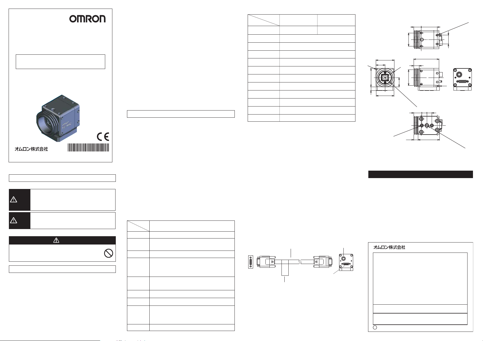
■接続
①カメラケーブル形FZ-VS□□(別売)で、カメラ裏側のコネクタとコ
ントローラ形FZシリーズ のカメラ接 続コネクタに 接 続します 。
カメラケーブル
FZ-VS□□
カメラケ ーブ ル
接続コネクタ
銘板
※カメラケーブル形FZ-VS、FZ-VSL、FZ-VSBには極性がありま
す。銘板の貼られている側をコントローラに接続してください 。
拡張コネクタ
カメラ
FZ-SHC
FZ-SH
■外形寸法
14.5
30.2
4-M4深さ4(4面共通)
25φ3 0
4-R3
35
17.5
φ3 6
357
17.5
1-32UN
34
2-M4深さ5.5
10.5
F(Cマウント)
15.5
48.2
9.5 9.5
40.98.3
ご使用に際してのご承諾事項
①安全を確保する目的で直接的または間接的に人体を検出する用途に、本製品を使用し
ないでくださ い 。同用途には、当社センサカタログに掲載している安全センサをご使用く
ださい 。
②下記用途に使用される場合、当社営業担当者までご相談のうえ仕 様 書などによりご確
認いただくとともに 、定格・性能に対し余裕を持った使い方や、万一故障があっても危険
を最小にする安全回路などの安全対策を講じてください 。
a)屋外の用途、潜在的な化学的汚染あるいは電気的妨害を被る用途
またはカタログ 、取扱説明書等に記載のない条件や環境での使用
b)原子力制御設備、焼却設備、鉄道・航空・車両設備、医用機械、娯楽機械、
安全装置、および行政機関や個別業界の規制に従う設備
c)人命や財産に危険が及びうるシ ステム・機械・装置
d)ガス、水道、電気の供給システムや24時間連続運転システムなどの
高い信 頼性が 必要な設 備
e)その他、上記a)〜d)に準ずる、高度な安全性が必要とされる 用 途
*上記は適合用途の条件の一部です。当社のベスト、総 合 カタログ・データシート等最新版
のカタログ、マニュアルに記載の保証・免責事項の内容をよく読 ん でご 使 用ください 。
インダ ストリア ル オートメーションビジ ネス カン パ ニ ー
●お問い合わせ先
カスタマサポートセンタ
フリーコ ール
携帯電話・PHSなどではご利用いただけませんので、その場合は下記電話番号へおかけください 。
電話
〔技術のお問い合わせ時間〕
■
■営 業 日:365日
■上記フリ−コ−ル以外のセンシング機器の技術窓口:
電話
〔営業のお問い合わせ時間〕
■
■営 業 日:土・日・祝祭日/春期・夏期・年末年始休暇を除く
●FAXによるお問い合わせは下記をご利用くださ い 。
●その他のお 問い 合わせ先
または貴社担当オムロン営業員にご相談ください 。
q
2009年10月
0120-919-066
055-982-5015
営業時間:8:00〜21:00
055-982-5002
営業時間:9:00〜12:00/13:00〜17:30(土・日・祝祭日は休業)
カスタマサポートセンタ お 客 様 相 談 室 FAX055-982-5051
納期・価格・修理・サンプ ル・仕様書は貴社のお取引先、
(通話料がかかります )
(通話料がかかります )
16.8
(1)
1
/4-20UNC深
(単位:mm)
さ
5.5
Page 2
Model
FZ-SHC/SH
HIGH SPEED DIGITAL CAMERA FOR
MODEL FZ VISUAL INSPECTION SYSTEM
INSTRUCTION SHEET
Thank you for selecting OMRON product. This sheet primarily describes precautions required in installing and
operating the product.
Before operating the product, read the sheet thoroughly to
acquire sufficient knowledge of the product. For your convenience, keep the sheet at your disposal.
TRACEABILITY INFORMATION:
Representative in EU:
Omron Europe B.V.
Wegalaan 67-69
2132 JD Hoofddorp,
The Netherlands
The following notice applies only to products that carry the CE mark:
Notice:
This is a class A product. In residential areas it may cause radio
interference, in which case the user may be required to take adequate
measures to reduce interference.
OMRON Corporation All Rights Reserved.
©
PRECAUTIONS ON SAFETY
Meaning of Alert Symbols
Indicates a potentially hazardous situation
which, if not avoided, will result in minor or
WARNING
moderate injury, or may result in serious
injury or death. Additionally there may be
significant property damage.
Indicates a potentially hazardous situation
CAUTION
which, if not avoided, may result in minor or
moderate injury or in property damage.
Alert statements
This product is not designed or rated for ensuring
safety of persons. Do not use it for such purposes.
PRECAUTIONS FOR SAFE USE
Be sure to respect following items for safety.
(1) Installation and Storage Site
Do not install and store the product in locations subjected to the
following conditions:
・ Ambient temperature outside the rating
・ Rapid temperature fluctuations (causing condensation)
・ Relative humidity outside the range of 35 to 85%
・ Presence of corrosive or flammable gases
・ Presence of dust, salt, or metallic particles
・ Direct vibration or shock
・ Reflection of intense light (such as other laser beams or electric
arc-welding machines)
・ Direct sunlight or near heaters
Manufacturer:
Omron Corporation,
Shiokoji Horikawa, Shimogyo-ku,
Kyoto 600-8530 JAPAN
Ayabe Factory
3-2 Narutani, Nakayama-cho,
Ayabe-shi, Kyoto 623-0105 JAPAN
2010
WARNING
・ Water, oil, or chemical fumes or spray
・ Strong magnetic or electric field
・Near high-voltage eqipment or power eqipment
(2) Handling the Camera
Make sure to tighten all installation screws securety.The
Camera’s case is connected to the 0V line in the internal circuits.
Observe the following precautions to prevent noise interference.
・ Do not ground the Camera.
・ Please use the plinth when you set it up.
(3) Others
・ Do not use unspecified camera cable and a strobe controller
other than those that specified in this manual with the FZ
controller. Connection with unspecified camera cable and/or
strobe controller may malfunction at the worst case.
・ If you do not use the enhancing connector on the back of the
camera, do not remove the cap that is attached to the connector.
・ Do not attempt to dismantle, repair, or modify the main body.
・ If you suspect an error or malfunction, stop using the Controller
immediately, turn OFF the power supply, and consult your
OMRON representative.
・ Dispose of FZ-SHC/SC components as industrial waste.
PRECAUTIONS FOR CORRECT USE
Please observe the following precautions to prevent failure to
operate, malfunction, or undesirable effect.
(1) Connecting Cables
・ Be sure to turn off the power before connecting or disconnecting the cables.
(2) Optical axis of the Camera.
・ The center of the optical axis varies with the camera used.
Therefore, when installing the camera, always check the center
of the image displayed on the monitor.
(3) Maintenance
・ If large dust particles adhere to the CCD, use a blowerbrush
(used to clean camera lenses) to blow them off. Do not blow the
dust particles with your mouth.
・
Do not use thinners, benzene, acetone, or kerosene to clean Camera.
(4) Imager
・ It is not a breakdown because of the structure of the taking
picture element though the line in the vertical direction might
enter the center of the image according to the measurement
condition and sensitivity.
■Specifications
General specifications
Item
Power consumption
Vibration
resistance
Shock
resistance
Ambient Temperature
Ambient
humidity
Ambient environment
Degree of protection
Materials
Weight
10 to 150Hz: half-amplitude: 0.35mm:
10 times each in X, Y, and Z directions for 8 min
(up/down, left/right, forward/backward)
Operating: 0 to 40 ℃
Storage: -25 to 65 ℃
Operating and storage: 35% to 85%
Thread part of mount :Low cadmium brass
FZ-SHC/SH
3.6W max.(DC12V, 0.3A max)
(maximum acceleration: 50m/s
Shock resistance 150m/s2 ;
3 times each in 6 directions
(with no icing nor condensation)
(with no icing nor condensation)
2
),
(with no condensation)
No corrosive gases
IEC60529 IP20 (in-panel)
Case :Aluminum alloy
Camera mount : PC/ABS
Approx. 105g (including base)
Performance specifications
Item
Picture element
Transmission mode
Effective pixels
Pixel size
Scanning method
Frame rate
FZ-SHC FZ-SH
1/3-inch color CCD
1/3-inch monochrome CCD
Interline reading all pixels
644(H)×484(V)
7.4(µm)×7.4(µm)(Square pixel)
Non-interlace mode
204fps
Number of lines to be
read
Synchronization
Video output
Gain
Shutter speed
12 lines to 480 lines
Internal Sync.
Digital (10 bits)
0dB to 18.34dB
1/10 to 1/50000s
Lens mounting C mount
■Accessories
Main unit, instruction sheet(this manual)
■Changing the Camera Base Mount Position
(1) The camera base attached to the bottom of the camera can also
be attached to the another side of the camera. Remove the four
screws(M4×8) from the base and re-attach the base to the
another side of the camera. (Recommended screw tightening
torque:1.2N・m)
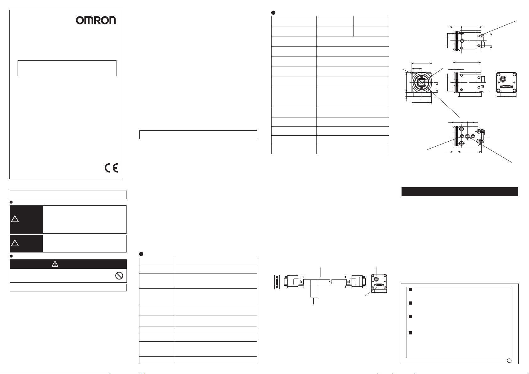
■Connecting
(1) Using the Camera cable FZ-VS□□(sold separately), connect
the connector on the back of the camera and the camera
connector on Controller FZseries.
Camera cable
FZ-VS□□
Name plate
*The camera cable (FZ-VS,FZ-VSL,FZ-VSB) is polarized, so, make
sure that the end bearing a name plate is connected to the Controller.
Enhancing connector
Camera cable
connector
Camera
FZ-SHC
FZ-SH
■Dimensions
14.5
30.2
4-M4 DEPTH4
(FOUR COMMONNESS)
2530Dia.
MO
10.5
UNT)
15.5
48.2
9.5 9.5
40.98.3
4-R3
35
17.5
357
34
3
2-M4 DEP
Dia.
6
17.5
1“-32UNF(C
TH5.5
Suitability for Use
THE PRODUCTS CONTAINED IN THIS SHEET ARE NOT SAFETY RATED.
THEY ARE NOT DESIGNED OR RATED FOR ENSURING SAFETY OF
PERSONS, AND SHOULD NOT BE RELIED UPON AS A SAFETY
COMPONENT OR PROTECTIVE DEVICE FOR SUCH PURPOSES.
Please refer to separate catalogs for OMRON's safety rated products.
OMRON shall not be responsible for conformity with any standards, codes, or
regulations that apply to the combination of the products in the customer's
application or use of the product.
Take all necessary steps to determine the suitability of the product for the
systems, machines, and equipment with which it will be used.
Know and observe all prohibitions of use applicable to this product.
NEVER USE THE PRODUCTS FOR AN APPLICATION INVOLVING
SERIOUS RISK TO LIFE OR PROPERTY WITHOUT ENSURING THAT THE
SYSTEM AS A WHOLE HAS BEEN DESIGNED TO ADDRESS THE RISKS,
AND THAT THE OMRON PRODUCT IS PROPERLY RATED AND
INSTALLED FOR THE INTENDED USE WITHIN THE OVERALL
EQUIPMENT OR SYSTEM.
See also Product catalog for Warranty and Limitation of Liability.
EUROPE
OMRON EUROPE B.V. Sensor Business Unit
Carl-Benz Str.4, D-71154 Nufringen Germany
Phone:49-7032-811-0 Fax: 49-7032-811-199
NORTH AMERICA
OMRON ELECTRONICS LLC
One Commerce Drive Schaumburg,IL 60173-5302 U.S.A.
Phone:1-847-843-7900 Fax : 1-847-843-7787
ASIA-PACIFIC
OMRON ASIA PACIFIC PTE. LTD.
No. 438A Alexandra Road #05-05-08(Lobby 2),
Alexandra Technopark, Singapore 119967
Phone : 65-6835-3011 Fax :65-6835-2711
CHINA
OMRON(CHINA) CO., LTD.
Room 2211, Bank of China Tower,
200 Yin Cheng Zhong Road,
PuDong New Area, Shanghai, 200120, China
Phone : 86-21-5037-2222 Fax :86-21-5037-2200
OMRON Corporation
16.8
(1)
1
/4
” -20UNC DE
(Unit:mm)
P
T
H5.5
o
 Loading...