

Page 1
形
FZ-DU
FZシリーズ用USB切替器
取扱説明書
このたびは、本製品をお買い上げいただきまして、まことにありがとうございます。
ご使用に際しては、次の内容をお守りください。
・電気の知識を有する 専門家がお取り扱いください。
・
この取扱説明書をよくお 読みになり、十分にご 理解のうえ、正しくご使用ください。
・この取扱説明書はいつでも参照できるよう大切に保 管してください。
■設置について
・ヒータ、トランスや大容量の抵抗など、発熱量の高い機器
の真上には取付けないでください。
・使用周囲温度は50℃以下にしてください。
・使用周囲温度が50℃に近い場合は、強制ファンやクーラ
を設置して、常時50℃を超えないようにしてください。
ファン
制御盤
■ 耐 ノイズ 性
・高圧機器の設置されている盤内には取付けないでください。
・動力線からは、200mm以上離してください。
200mm以上
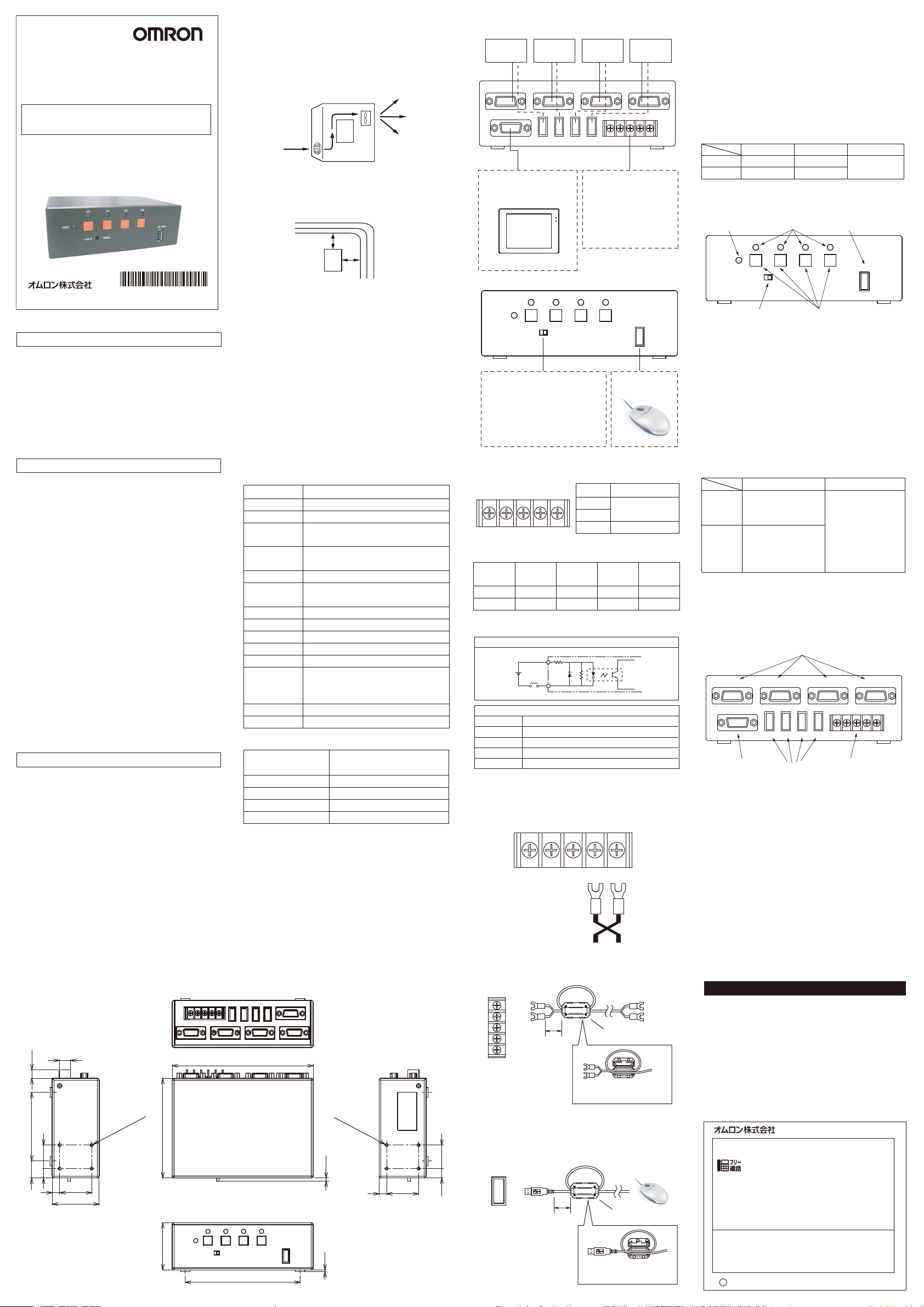
■システム 構 成
コ ント ロ ー ラ
No.0
モニタケーブ ル
(オス-メス)
VIDEO IN No.0
VIDEO OUT
選 択されたチャンネル に接 続
さ れ て い る コ ント ロ ー ラ の モ ニ
タ 画 面 を出 力します 。
コ ント ロ ー ラ
VIDEO IN No.1
No.0 No.3 IN0 IN1
形FZ-VM
No.1
コ ント ロ ー ラ
No.2
VIDEO IN No.2 VIDEO IN No.3
USB OUT
■端子台入力部
・外部機器
プ ロ グ ラ マ ブ ル コ ント ロ ー ラ
などにより 接 続 チャン ネ ル の
切替が可能です。
・電源入力
DC24Vを入力してください。
コ ント ロ ー ラ
No.3
( A タイプ オス - A タイプ オ ス)
COM IN 24VDC
+ -No.2 No.1
USBケーブル
■端子部分やコネクタ内部に触れるとき
静電気による破損を防ぐため、端子部分やコネクタ内部
の信号線に触れる場合は、リストストラップなどを使用して
帯電防止措置を行ってください。
■電源端子台への配線
端子台の端子ねじはM3を使用しています。M3のネジに合
った圧着端子をご用意ください。端子ねじは締付けトルク0.5
〜0.6N・mで確実に締付けてください。
推奨品
メーカ ー
フォーク 型丸型日本圧着端子
日本圧着端子
形式 推奨電線サイズ
V1.25-N3A
V1.25-MS3
0.3〜1.65mm
■各部の名称
(1)前 面 パネル
① ②
CH1 CH2 CH3
CH0
⑤
2
OMRON Corporation
©
* 2 1 3 4 8 1 2 - 5 D *
2010 All Rights Reserved.
安全上のご注意
以下に示すような項目は安全を確保する上で必要なこと
ですので必ず守ってください。
・引火性・爆発性ガスの環境では使用しないでください。
・製 品 の 分 解・修 理・改 造 をし な い でくださ い 。
・定格範囲を超える電圧、電流を印加しないでください。
・電源の逆接続および交流電源への接続はしないでくだ
さい 。
・廃棄するときは、産業廃棄物として処理してください。
安全上の要点
・下記の設置場所では使用しないでください。
・直 射日光があたる場所
・湿度が高く結露する恐れのある場所
・腐食性ガスのある場所
・本体に直接、振動や衝撃が伝わる場所
・配線は高圧、強電流線との接近を避けてください。
・万一、異常を感じたときは、すぐに使用を中止し、電源を
切 っ て ください 。
・お手入れは電源を切って、安 全を確認してから行って下
さい。本線品の汚 れ は、やわらかい 布で軽く拭き取り、パ
ネル面の汚れはエアブラシを使用して取り除いて下さい。
ベンジン や シンナ ー 等 の 溶 剤 は 使 用しない で 下 さい 。
・法 規と規 格
本製品は、以下の規格に準拠しています。
EN規格(ヨーロッパ規格)EN61326-1
Electromagneticenvironment:Industrial
electromagneticenvironment
(EN/IEC61326-1Table2)
また本製品は、イミュニティ試験において、以下の条件を
適 用しています 。
:モニタ表示において、文字が判読可能な映像の乱れは
合格とする。
使用上の注意
システムの信頼性をより高め、その機能を十分に発揮させ
るために、以下の内容を必ず守って設置してください。
■設置場所について
次のような場所には設置しないでください。
・周囲温度が0〜50℃の範囲を超える
・温度変化が急激で結露する
・周囲湿度が35〜85%の範囲を超える
・廃食性ガス、可燃性ガスがある
・塵桙、塩分、鉄粉が多い
・1.5G以上の振動や衝撃がかかる
・直 射日光があたる
・水・油・化 学 薬 品 の 飛 沫 が ある
・強磁界、強電界がある
■設置方向について
設置方向は、通常の据え置き設置方向のみです。
その他の方向に設置しないでください。
■外形寸法
12
(9)
4-M3深さ3
18 73
2510
(取付用ねじ穴)
34
8
50
106
50
200mm以上
■ケーブルの着脱について
ケーブルを着 脱するときは必ず電源を切ってください。
・取 付 け るとき
樹脂モールド部を持ってコネクタの切り欠きを確認し、まっ
すぐに差し込んでください。
・外 す とき
まっすぐに引き抜きます。樹 脂モールド部 やケーブルを 持っ
て 、無 理 に 引 き 抜 か な い で く だ さ い 。
■用途
本ユニットは、複数のコントローラ(最大4台)を1台のUSB
入力機器(マウスなど)と1台のモニタを用いて、切替て操
作 す る 為 の F Z シリー ズ 専 用 の オ プ ション 機 器 で す 。
■仕様
(1)一般仕様
項目 仕様
電源電圧
消費電流
絶縁抵抗
耐電圧
漏れ電流
耐振動
使用周囲温度
使用周囲湿度
保存温度
使用周囲雰囲気
保護構造
環境条件
材質
質量
(2)性能仕様
USB入力インタフェース
USB出力インタフェース
モニタ入力インタフェース
モ ニタ 出 力 イン タフェース
チャン ネル 切 替
※モニタのDDCには対応していません。
※入力機器として使用できるUSBマウスなどへの電源供
給容量は、300mA以下です。
※CH切替(押しボタン、外部入力)は500ms以上間隔を
あけ てください 。
※USBマウスなどの種類によっては接続できないものが
ありま す 。
(3)付属品
取扱説明書1部、フェライトコア2個
150
122.2
D C 2 0 .4 〜 2 6 .4 V
200mA以下
DC入力端子一括とケース間:
20MΩ以上(DC500Vメガーにて)
DC入力端子一括とケース間:
AC1000V 50/60Hz 1min
1mA 以 下
振動周波数10〜150Hz 片振幅0.1mm
X,Y,Z各方向 1掃引8分×10掃引
0〜50℃
35〜85%RH(ただし、氷結・結露のないこと)
−5〜+ 55℃
腐食性ガス、塵埃のないこと
盤内蔵型(IP20)
屋内使用 高度2000mまで
公称電圧の10%を超えない電源電圧の変動
設置カテゴリⅡ IEC664による汚染程度2
ケース:ABS/PC
約500g
TypeA 1ch(マウス・トラックボール
などの入力デバイス機器専用)
TypeA 4ch(同時出力は不可)
4ch(アナログRGBビデオ)
1ch(アナログRGBビデオ)
チャンネル切替ボタンまたは外部信号
4-M3深さ3
(取付用ねじ穴)
3.5
348
(2)
(単位:mm)
形FZ-M08
POWER
■モード切替SW
・MANUAL
前面のチャンネル切 替ボタンにより、
接続チャンネルの切替が可能です。
・REMOTE
外部入力により、接続チャンネルの切
替が 可 能です 。
■外部入力仕様
COM IN 24VDC
IN0 IN1
外部チャンネル切替信号とチャンネルの関係は以下の通りです。
外部信号
IN 0
IN 1
(2)チャンネル切替信号の入力仕様
回路図
+
各入力端子
性能
入力電圧
ON電流
ON電圧
OFF電流
OFF電圧
※COMIN電圧:24V
誘電ノイズによる影響を避けるため、電線はツイストして使
用 し て ください 。
電源線には、付属品のフェライトコアを取付けてください。取
付位置はFZ-DU側端子から約10mm離した所です。
端子台
マウスには、付属品のフェライトコアを取付けてください。取
付位置はFZ-DU側コネクタから約10mm離した所です。
2510
USB INPUT
USB入力機器
接続用コネクタ
CH1 CH2 CH3
CH0
MANUAL
REMOTE
+ -
チャン ネル
N o .0
COMIN
DC12〜24V±10%
2〜15mA
2V以下
0.1mA以下
10V以上
チャン ネル
OFF
OFF
COM IN 24VDC
IN0 IN1
約10mm
約10mm
USBインタフェース
( マウスなど)
信号名 機能
IN0
IN1
COMIN
N o .1
ON
OFF
外部チャンネル切替
入力信号用コモン
チャン ネル
N o .2
OFF
ON
+ -
フェライトコア
フ ェ ラ イト コ ア の 中 で ケ ー ブ
ルを一回巻いてください。
フェライトコア
フ ェ ラ イト コ ア の 中 で ケ ー ブ
ルを一回巻いてください。
USB INPUT
チャン ネル
N o .3
ON
ON
USBインタフェース
( マウスなど)
POWER
REMOTE
MANUAL
④
③
USB INPUT
①電源表示LED
電源ON時に緑色に点灯します。
②使用チャンネル表示LED
チャンネルNo.0からNo.3のうち、選択されているチャン
ネルに対応するLEDが緑色に点灯します。
③ チャンネ ル 切 替 ボタン
チャンネルNo.0からNo.3のうち、選択したいチャンネル
に対応するボタンを押 すことにより、チャンネルを切り替
えることが で きます 。モード 切 替 SW が「 MANUAL 」の
場合のみ、有効です。
④ モ ード 切 替 ス イッ チ
操 作 モ ード を 切 り 替 え る ス イッ チ で す 。
MANUAL
REMOTE
チャン ネル 切 替
前面の③チャンネル切
替 ボタン に より選 択 でき
ます 。
外部入力によりチャンネ
ルを選択できます。前面
の チャン ネル 切 替 ボタン
によ る切 替 は できませ ん 。
コンソー ル 操 作
前 面のUSB入力コネク
タに接続した機器によ
り操 作 できます 。
⑤USB入力機器接続用コネクタ
USBマウスなどを接続します。(ただし、電源供給容量
300mA以下)
※USBマウスなどの種類によっては接続できないものが
ありま す 。
(2)裏面パネル
VIDEO IN No.0
VIDEO OUT
VIDEO IN No.1
No.0 No.3 IN0 IN1
①
VIDEO IN No.2 VIDEO IN No.3
USB OUT
COM IN 24VDC
+ -No.2 No.1
③② ④
①モニタ入力接続用コネクタ(オス)
モニタケーブ ル ( メス)を接 続します 。FZコントローラからの
モニタ入 力を最 大4本まで接 続 することができます 。
適合ケーブル:Dsub高密度15芯オス/メス両サイド:
#4-40ネジケーブル
②
モニタ出 力 ケーブ ル 接 続 用 コネクタ(メス)( 形FZ−VM用 )
モニタケーブル 形FZ−VMを 接 続します 。選 択されたチャ
ンネルに 接 続され ているコントローラのモニタ画面を出 力
します 。
③端子台
外部機器からチャンネル切替を行う場合に使用します。
電源入力部には、電源線を接続します。必ず、付属のカ
バ ー を 取 り 付 け た 状 態 で ご 使 用 くだ さい 。
④USB出力接続用コネクタ
FZコントローラへの出 力を最 大4本まで 接 続 することがで
きます 。
適合ケーブル:USBType-Aオス/オスケーブル
ご承諾事項
当社商品は、一般工業製品向けの汎用品として設計製造されています。従いまして、次に
掲げる用途での使用を意図しておらず、お客様が当社商品をこれらの用途に使用される際
には、当社は当社商品に対して一切保証をいたしません。ただし、次に掲げる用途であって
も当社の意図した特別な商品用途の場合や特別の合意がある場合は除きます。
(a)高い安全性が必要とされる用途(例:原子力制御設備、燃焼設備、航空・宇宙設備、鉄
道設備、昇降設備、娯楽設備、医用機器、安全装置、その他生命・身体に危険が及び
うる用途)
(b)高い信頼性が必要な用途(例:ガス・水道・電気等の供給システム、24時間連続運転
システム、決済システムほか権利・財産を取扱う用途など)
(c)厳しい条件または環境での用途(例:屋外に設置する設備、化学的汚染を被る設備、
電磁的妨害を被る設備、振動・衝撃を受ける設備など)
(d)カタログ等に記載のない条件や環境での用途
*(a)から(d)に記載されている他、本カタログ等記載の商品は自動車(二輪車含む。以下同
じ)向けではありません。自動車に搭載する用途には利用しないで下さい。自動車搭載
用商品については当社営業担当者にご相談ください。
*上記は適合用途の条件の一部です。当社のベスト、総合カタログ、データシート等最新版
のカタログ、マニュアルに記載の保証・免責事項の内容をよく読んでご使用ください。
●製品に関するお問い合わせ先
お客様相談室
インダストリアル オートメーションビジネスカンパ ニー
クイック オムロン
0120-919-066
携帯電話・PHS・IP電話などではご利用いただけませんので、下記の電話番号へおかけください。
電話
055-982-5015
■営業時間:8:00〜21:00 ■営業日:365日
●FAXやWebページでもお問い合わせいただけます。
FAX055-982-5051/www.fa.omron.co.jp
●その他のお問い合わせ
納期・価格・サンプル・仕様書は貴社のお取引先、または貴社
担当オムロン販売員にご相談ください。
オムロン制御機器販売店やオムロン販売拠点は、Webページで
ご案内しています。
v
A
2014年7月
(通話料がかかります)
Page 2
Model
FZ-DU
USB Switcher for FZ Series
INSTRUCTION SHEET
Thank you for selecting OMRON product. This sheet
primarily describes precautions required in installing and
operating the product.
Before operating the product, read the sheet thoroughly to
acquire sufficient knowledge of the product. For your
convenience, keep the sheet at your disposal.
TRACEABILITY INFORMATION:
Importer in EU :
Omron Europe B.V.
Wegalaan 67-69
2132 JD Hoofddorp,
The Netherlands
The following notice applies only to products that carry the CE mark:
Notice:
This is a class A product. In residential areas it may cause radio
interference, in which case the user may be required to take adequate
measures to reduce interference.
OMRON Corporation
©
PRECAUTIONS ON SAFETY
Please observe the following content.
·Do not use it in locations subject to explpsove or
flammable gases.
·Do not attempt to disassemble, repair, or modify the
Product.
·Do not impose voltage exceeding the rated voltage.
·When supplying power to the Sensor, make sure that the
polarity of the power is correct, and do not connect to an
AC power supply.
·When disposing of the USB Switcher ;treat it as
industrial
PRECAUTIONS FOR SAFE USE
Do not install the USB Switcher in the following
locations.
·Locations subject to direct sunlight.
·Locations where the relative humidity exceeds the range
of 35% to 85%.
·Locations subject to corrosive or flammable gases.
·Locations subject to direct vibration or shock.
·Locations subject to strong electromagnetic or electrical
fields.
·If you notice any abnormality in the USB Switcher, stop
using it immediately, turn OFF the power supply, and
contact your OMRON sales representative.
·Regulations and Standards
This product is compliant with the standards below:
EN Standards(European Standards), EN61326-1
Electromagnetic environment : Industrial
electromagnetic environment
(EN/IEC 61326-1 Table 2)
Also, the following condition is applied to the immunity
test of this product.
: If the level of disturbance of the video is that with
characters on the monitor are readable, the test is pass.
PRECAUTIONS FOR CORRECT USE
Observe the following precautions to prevent the product
from malfunctioning, becoming inoperable, or the
performance and/or the device from being adversely
affected:
■About installation features
·Ambient temperature outside the rating
·Rapid temperature fluctuations (causing condensation)
·Relative humidity outside the range of 35 to 85%
·Presence of corrosive or flammable gases
·Presence of dust, salt, or iron particles
·Direct vibration or shock
·Direct sunlight
·Water, oil, or chemical fumes or spray
·Strong magnetic or electric field
■Orientation of Product
Use only the same orientation as floor mounting for
installation of the product. Do not use any other
orientation for installation of the product.
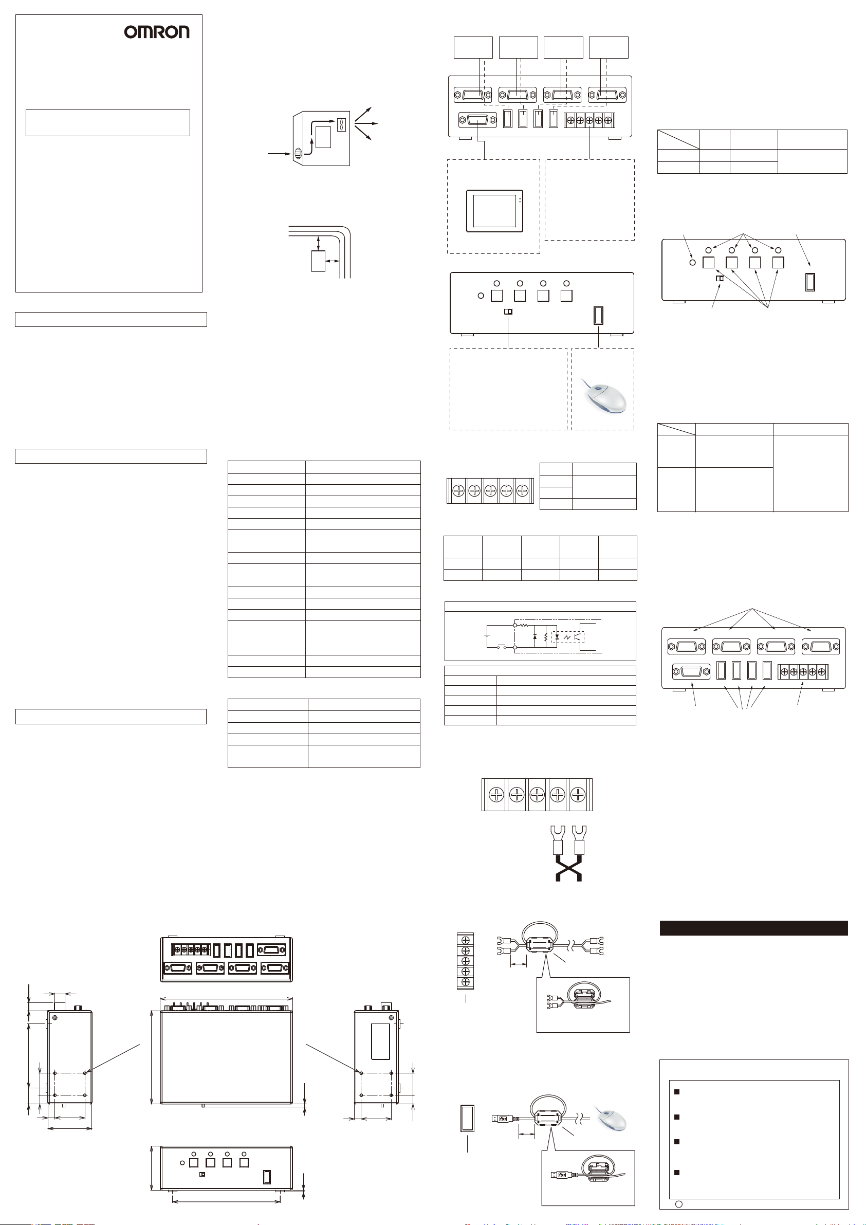
■Dimensions
12
(9)
2510
18 73
34
8
50
Manufacturer:
Omron Corporation,
Shiokoji Horikawa, Shimogyo-ku,
Kyoto 600-8530 JAPA N
2010 All Rights Reserved.
4-M3 DEPTH3
(mounting screw hole)
106
50
■About the installation
·Please do not install it on the equipment with a high
calorific value.
·Please adjust the ambient temperature of the
specification to 50℃ or less.
·Please never exceed 50℃ by setting up the compulsion
fan and the air conditioner when the ambient
temperature of the specification is near 50℃.
Control panel
Fan
■Noise immunity
·Please do not install it in the board where the
high-pressure installation is set up.
·Please separate from the power line by 200mm or more.
200mmormore
200mmormore
■About detaching the cable
Please turn off power when you detach the cable.
·Mounting
Please insert it straight with the part of the resin.
·Detaching
Please pull it out straight.
■Application
This unit is an option equipment only for the FZ series to
switch by using one USB input equipment (mouse etc.)
and one monitor and to operate two or more controllers
(4 or less).
■Specifications
(1)General specifications
Item Specification
Power supply voltage
Current consumption
Insulation resistance
Dielectric strength
Leakage current
Vibration resistance
Ambient temperature
Ambient humidity
Storage temperature
Ambient environment
Degree of protection
Environmental con
Materials
Weight
(2)Performance specifications
USBinputinterface
USBoutputinterface
USBinputinterface
USBoutputinterface
Channelswitch
*It doesn't correspond to DDC of the monitor.
*The power supply capacity is 300mA or less.
*Please leave space about 500ms or more about the
channel switch.
*It is not likely to be able to connect it according to USB
mouse's kind etc.
(3)Accessories
Instruction sheet(this sheet)
Ferrite core···2
150
122.2
DC20.4 to 26.4V
MAX:200mA
20MΩmin. at 500V DC
1000V AC. 50/60 Hz for 1 min
1mA or less
10 to 150Hz: half-amplitude: 0.1mm
10 times each in X, Y, and Z directions for 8 min
0 to 50℃
Operation and storage: 35 to 85 %
(with no icing nor condensation)
-5 to +55℃
No corrosive gases
IP20
The indoor use
dition
The high degree : up to 2000m.
IEC664 Pollution extent 2
Case:ABS/PC
Approx:500g
TypeA1ch
TypeA4ch
4ch(AnalogRGBvideo)
1ch(AnalogRGBvideo)
Channelswitchbuttonor
externalsignal
4-M3 DEPTH3
(mounting screw hole)
3.5
348
(2)
(UNIT:mm)
2510
■System configuration
Controller
No.0
Monitor cable
VIDEO IN No.0
VIDEO OUT
The monitor screen is
output.
POWER
■Mode switch
·MANUAL
The switch of the channel is
possible by a channel switch
button.
·REMOTE
The switch of the channel is
possible by an external input.
Controller
No.1
VIDEO IN No.1
USB OUT
No.0 No.3 IN0 IN1
FZ-VM
FZ-M08
CH1 CH2 CH3
CH0
MANUAL
REMOTE
Controller
No.2
VIDEO IN No.2 VIDEO IN No.3
■Terminal stand input
・External instrument
The channel can be
switched as a
programmable controller
etc.
・Power supply input
DC24V is input.
Controller
No.3
USB cable
COM IN 24VDC
+ -No.2 No.1
USB INPUT
USB interface
■External input
COM IN 24VDC
IN0 IN1
Relation between switch signal and channel.
External
signal
IN0
IN1
(2)Input specification
Circuit
+ -
Channel
No.0
OFF
OFF
COM IN
+
Input terminal
Performance
Input voltage
On current
On voltage
Off current
Off voltage
*COM IN Voltage:24V
DC12 to 24V±10%
2 to 15mA
2V or less
0.1mA or less
10V or more
Please do the twist to the electric wire to avoid the
inductive noise.
IN0 IN1
Please install an accessory ferrite core on the power
supply line. The installation position is a place separated
from the FZ-DU side terminal by approx 10mm.
Approx 10mm
Terminal stand
Please install an accessory ferrite core in the mouse. The
installation position is a place separated from the FZ-DU
side connector by approx 10mm.
USB INPUT
Approx 10mm
USB input device
connection connector
Signal Function
IN0
IN1
COM IN
Channel
No.1
ON
OFF
External switch
Channel
No.2
OFF
ON
COM IN 24VDC
+ -
Ferrite core
Please roll the cable
once in the ferrite core.
Ferrite core
Please roll the cable
once in the ferrite core.
Common
Channel
No.3
ON
ON
USB interface
■When you touch the terminal and
the connector area
Please do the electrification prevention with a list strap.
■Wiring to power supply terminal
The screw of the terminal stand uses M3. Please use the
pressure terminal that fits the screw of M3.
Tightening torque:0.5 to 0.6N·m
Recommended parts
Size of recommended
electric wire
0.3 to 1.65mm
2
Fork type
Round type
Maker
JST
JST
Model
V1.25-N3A
V1.25-MS3
■Name of each part
(1)Front panel
① ②
CH1 CH2 CH3
CH0
POWER
MANUAL
REMOTE
④
①Power supply display LED
It lights to green in power supply ON.
②Channel display LED
LED of the selected channel lights to green.
③Channel switch button
The switch of the channel is possible.
④Mode switch
It is a switch that changes the operation mode.
Channel switch Console operation
MANUAL
REMOTE
It is possible to select it
with a front channel
switch button.
It is possible to select it by
an external input. It is not
possible to switch with a
front channel switch button.
⑤USB input device connection connector
The USB mouse are connected.(The power supply
capacity is 300mA or less.)
*It is not likely to be able to connect it according to
USB mouse's kind etc.
(2)Back panel
①
VIDEO IN No.0
VIDEO OUT
VIDEO IN No.1
USB OUT
No.0 No.3 IN0 IN1
①For monitor input
The monitor cable is connected. It is possible to
connect it up to four.
Applicable cable: 15 Pin HD D-Sub Male/Female :
#4-40Screw cable(Both sides)
②For monitor output
FZ-VM is connected. The monitor screen of the
controller who has been selected is output.
③Terminal stand
When switching from the external instrument, it uses
it. Please set the cover of the attachment.
④For USB output
Four outputs or less to the FZ controller can be
connected.
Applicable cable: USB Type-A Male/Male cable
Suitability for Use
Omron Companies shall not be responsible for conformity with any standards,
codes or regulations which apply to the combination of the Product in the
Buyer’s application or use of the Product. At Buyer’s request, Omron will
provide applicable third party certification documents identifying ratings and
limitations of use which apply to the Product. This information by itself is not
sufficient for a complete determination of the suitability of the Product in
combination with the end product, machine, system, or other application or
use. Buyer shall be solely responsible for determining appropriateness of the
particular Product with respect to Buyer’s application, product or system.
Buyer shall take application responsibility in all cases.
NEVER USE THE PRODUCT FOR AN APPLICATION INVOLVING
SERIOUS RISK TO LIFE OR PROPERTY WITHOUT ENSURING THAT THE
SYSTEM AS A WHOLE HAS BEEN DESIGNED TO ADDRESS THE RISKS,
AND THAT THE OMRON PRODUCT(S) IS PROPERLY RATED AND
INSTALLED FOR THE INTENDED USE WITHIN THE OVERALL
EQUIPMENT OR SYSTEM.
See also Product catalog for Warranty and Limitation of Liability.
OMRON Corporation
Tokyo, JAPAN
Regional Headquarters
OMRON EUROPE B.V.
Sensor Business Unit
Carl-Benz-Str. 4, D-71154 Nufringen, Germany
Tel: (49) 7032-811-0/Fax: (49) 7032-811-199
OMRON ELECTRONICS LLC
2895 Greenspoint Parkway, Suite 200
Hoffman Estates, IL 60169 U.S.A.
Tel: (1) 847-843-7900/Fax: (1) 847-843-7787
OMRON ASIA PACIFIC PTE. LTD.
No. 438A Alexandra Road # 05-05/08 (Lobby 2),
Alexandra Technopark,
Singapore 119967
Tel: (65) 6835-3011/Fax: (65) 6835-2711
OMRON (CHINA) CO., LTD.
Room 2211, Bank of China Tower,
200 Yin Cheng Zhong Road,
PuDong New Area, Shanghai, 200120, China
Tel: (86) 21-5037-2222/Fax: (86) 21-5037-2200
s
Oct, 2014
D
Industrial Automation Company
Contact: www.ia.omron.com
⑤
USB INPUT
③
It operates it with the
equipment connected
with the USB input.
VIDEO IN No.2 VIDEO IN No.3
COM IN 24VDC
+ -No.2 No.1
③② ④
 Loading...