

Page 1
画像処理システム
FZ5-L35□
FZ5-L35□-10
形
安全上の要点
使用上の注意
−推奨電線サイズ:1.31〜2.63mm
2
−圧着端子
−端子ねじ:M4
8.5mm以下 8.5mm以下
●設置環境について
・引火性、爆発性ガスの環境では使用しないでください。
・通風口をふさがないように本体を設置してください。
・通気口の吐き出し口に埃や粉塵がつまらないように、定期的に
清掃をしてください。通気口の吐き出し口がふさがると内部に
熱がこもり、故障の原因になります。
・操作、保守の安全性を確保するため、高圧機器や動力機器から
離して設置してください。
・取付けにおいて、ねじの締め付けは確実に行ってください。
●電源、配線について
・本書で指定した電源電圧で使用してください。
・ケーブル、圧着端子は、指定サイズのものを使用してください。
撚り合わせただけの電線を直接端子台に接続しないでください。
・電源線の長さができるだけ短くなるように(最大10mまで)配線
してください。
・電源は、高電圧が発生しないように対策(安全超低電圧回路)さ
れている直流電源装置から供給してください。
・電源投入前に、再度以下の確認をしてください。
−電源電圧は正しいか?(DC24V)
−出力信号の負荷は短絡状態ではないか?
−出力信号の負荷電流は適切か?
−配線に誤りは無いか?
●接地について
・コントローラの電源回路は内部回路と絶縁されていません。
・コントローラに接続するカメラは、必ず台座を使用して取り付
けてください。金属製筐体のカメラ本体の外郭はSG(0V)で
すので、台座が無い場合には、SG(0V)とFGが短絡する恐
れがあります。
・コントローラの筐体はSG(0V)に接続されていますので、直
接取り付けるとお客様装置のFGと短絡します。絶縁脚を介し
て取り付けてください。
・DC24V電源のプラス(+)端子は接地しないでください。プラス
接地した場合、コントローラやカメラの筐体などSG(0V)部に
触れると感電する恐れがあります。
●その他
・専用のカメラ、ケーブル以外を使用しないでください。誤動
作、破損の恐れがあります。
・カメラやケーブル類を着脱するときは、必ずセンサコントローラ
の電源を切ってください。電源を供給している状態で、ケーブル
を接続すると、カメラまたは周辺機器の破損の原因になります。
・この製品を分解したり、修理、改造しないでください。
・万一、異常を感じたときには、すぐに使用を中止し、電源を切
った上で当社支店・営業所までご相談ください。
・通電中や電源を切った直後は、蛍光灯、ハロゲンランプに触ら
ないでください。
・廃棄するときは、産業廃棄物として処理してください。
・製品を落下させたり、異常な振動・衝撃を与えないでください。
製品の故障、焼損の可能性があります。
・取扱い時は落下などに注意してください。
・リチウム電池を内蔵しており、発火、破裂により重度の障害が稀
に起こる恐れがあります。
・ケーブルの繰り返し屈曲が発生する箇所は、ケーブルが破損します
ので、ロボットケーブルタイプ(耐屈曲タイプ)を使用してください。
・ケーブルにねじりストレスを与えないでください。ケーブルが破
損する原因となります。
・ケーブルの最小曲げ半径を確保してください。確保できない場
合、ケーブルが破損する原因となります。
●法規と規格
本コントローラは、以下の規格に準拠しています。
EC指令 2004/108/EC
EN規格(ヨーロッパ規格)EN61326-1
CSA規格 CSAC22.2No.61010-1
●設置場所、保管場所について
次のような場所に設置、保管してください。
・周囲温度が0〜50℃(保管時−20〜+65℃)の場所
・温度が急激に変化しない場所(結露しない場所)
・相対湿度が35〜85%RHの場所
・腐食性ガス、可燃性ガスのない場所
・塵埃、塩分、鉄粉のない場所
・振動や衝撃のない場所
・直射日光があたらない場所
・水・油・化学薬品の飛沫がない場所
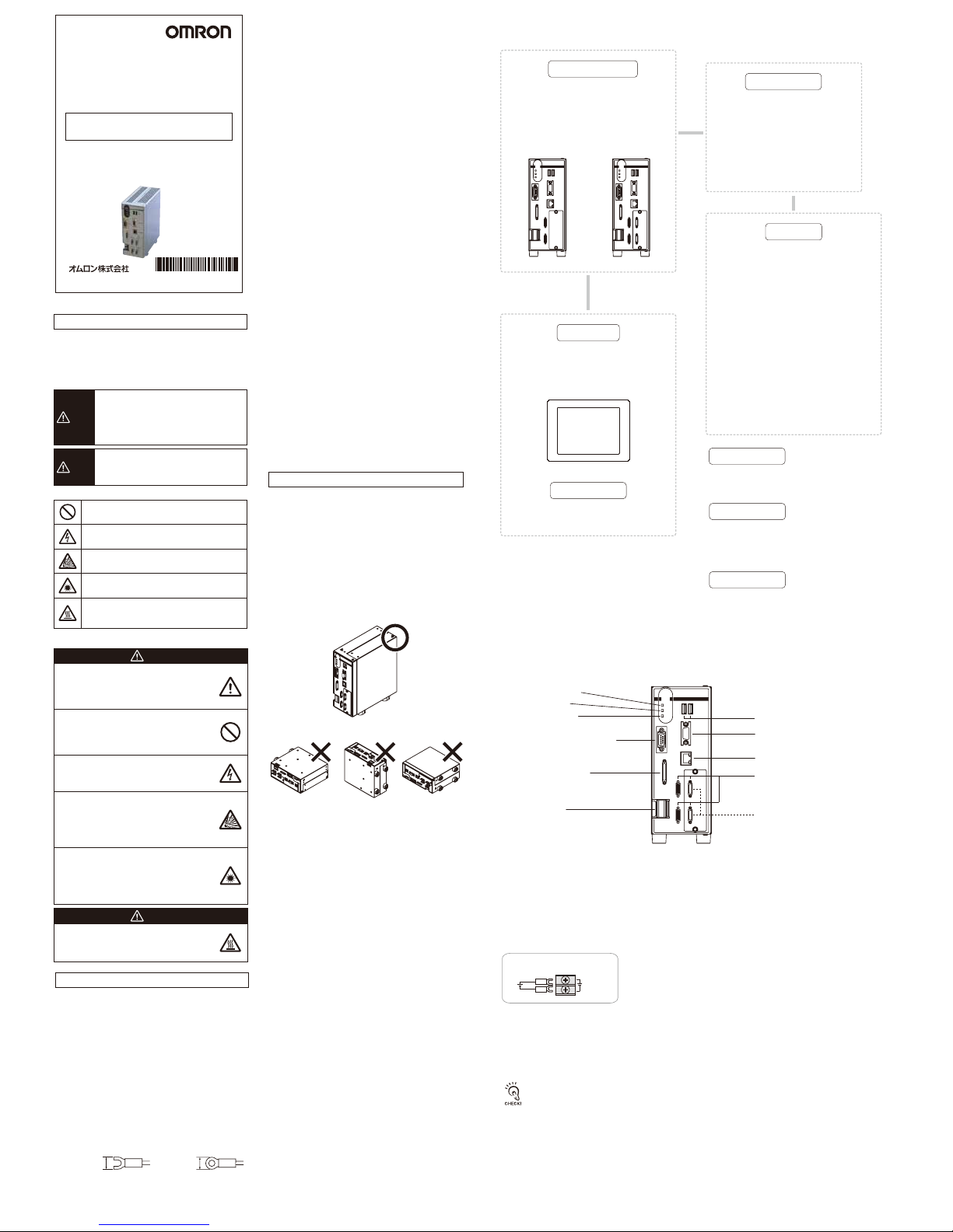
●設置方向
放熱を良くするため、下記の方向のみで設置してください。
●周囲温度
・通風を良くするため、コントローラの上部は他の機器と
50mm以上の間隔をあけて下さい。左右と背面は、他の機器
またはコントローラと25mm以上隙間を空けて設置してくだ
さい。
・ヒータ、トランスや大容量の抵抗など、発熱量の高い機器の
真上には取付けないでください。
・使用周囲温度は50℃以下にしてください。
・使用周囲温度が50℃に近い場合は、強制ファンやクーラーを
設置して、常時50℃を超えないようにしてください。
●耐ノイズ性
・高圧機器の設置されている盤内には取付けないでください。
・動力線からは、200mm以上離してください。
●構成品の設置や取扱いについて
・信号線に触れる
端子部分やコネクタ内部の信号線に触れる場合は、静電気に
よる破損を防ぐため、リストストラップなどを使用して帯電
防止措置を行ってください。
・USBメモリの取扱い
USBメモリを取外す場合は、データの読み/書き中でないこと
を確認して取外してください。データの読み/書き中はUSB
メモリ本体のLEDが点滅しますので、点灯状態になったこと
を確認して取り外してください。
・電源を切る
処理を実行中であることを示すメッセージが画面に表示されて
いるときは、電源をOFFしないでください。メモリ上のデータ
が破損し、次に起動したとき正常に動作しません。
・RESET信号について
電源ON直後にRESET入力をしないでください。起動タイミ
ングを同期させるためなどにRESET入力を使用する場合は、
コントローラの電源をONした後、15秒以上おいてから
RESET信号をONしてください。
●メンテナンスについて
・お手入れをするときは、電源を切って、安全を確認してから
行ってください。
・レンズの汚れは、レンズ専用の布、またはエアブラシを使用
して取除いてください。
・装置の汚れは柔らかい布で軽く拭き取ってください。
・CCDの汚れは、エアブラシを使用して取除いてください。
・シンナー、ベンジンは使用しないてください。
●上位機器との通信について
本製品の起動を確認後、上位機器との通信を行ってください。
また、本製品の起動時は上位インターフェースから不定な信号
が出る可能性がありますので、初期動作時はご使用機器の受信
バッファをクリアするなどの処置を実施してください。
この製品はカリフォルニア州法で規制されている過塩素酸塩を含むリチウムバッテリを内蔵しておりますので、この州法へ
の対応をしてください。
詳しくは、下記URLをご覧ください。
www.dtsc.ca.gov/hazardouswaste/perchlorate
■米国カリフォルニア州過塩素酸塩規制について
■基本構成
■各部の名称とはたらき
*印は専用品です。これら以外は使用できません。
USBメモリ
形FZ-MEM2G
形FZ-MEM8G
マウス、トラックボール
(USBインタフェースの市販品)
推奨品
オムロン(株)製
形S8VS-12024(FZ5-L35□)
形S8VS-18024(FZ5-L35□-10)
*
単体カメラ
形FZ-SC/形FZ-S/
形FZ-SC2M/形FZ-S2M/
形FZ-SC5M2/形FZ-S5M2/
形FZ-SFC/形FZ-SF/
形FZ-SPC/形FZ-SP/
形FZ-SHC/形FZ-SH
インテリジェントコンパクトカメラ
形FZ-SQ010F/形FZ-SQ050F/
形FZ-SQ100F/形FZ-SQ100N
インテリジェントカメラ
形FZ-SLC15/形FZ-SLC100
オートフォーカスカメラ
形FZ-SZC15/形FZ-SZC100
*
設定条件に従った画像処理を行い、
計測結果を出力する部分です。
カメラ2chタイプ
形FZ5-L350
形FZ5-L355
このような方向で設置しないでください
カメラ4chタイプ
形FZ5-L350-10
形FZ5-L355-10
セ ン サ コ ント ロ ー ラ
液晶モニタ
形FZ-M08(8.4インチ)
形FZ-VM(2m、5m、最小曲げ半径75mm)
モニタケーブル
*
*
画像の確認や条件設定用メニュー
を表示するために使用します。
計測物を画像として取込む部分です。
カメラ
電源装置
周辺機器
入力デバイス
*
電源の配線
24VDC
+
−
①通電中、点灯します。
②計測モードに入っている間、点灯します。
③異常が発生したときに点灯します。
④同期センサ、プログラマブルコントローラなどの外部装置と接続します。
⑤カメラを接続します。
⑥DC電源を接続します。他の機器とは独立して配線してください。配線後は、端子カバー(透明)を元の
場所に取付けてください。
・USBコネクタの接続対象は右記のとおりです。 ・市販のトラックボール、マウス、USBメモリ
・計測稼働中にUSB機器を抜き差ししないでください。計測時間への影響やデータ破壊の可能性があります。
⑦モニタを接続します。
⑧パソコン、プログラマブルコントローラなどの外部装置と接続します。
⑨パソコン、プログラマブルコントローラなどの外部装置と接続します。
⑩マウス、メモリなどを接続します。2ポートありますが、どちらを使用しても問題ありません。ただし両
方のポートにUSBメモリを接続すると、USBメモリ同士が接触し誤動作や破損の恐れがあります。
①POWERLED
⑩USBコネクタ
⑦モニタ接続コネクタ
(アナログRGB)
⑨イーサネット接続コネクタ
⑤カメラコネクタ
カメラ4chタイプのみ
(形FZ5-L35□-10)
⑧RS-232C接続コネクタ
⑥電源端子
④入出力コネクタ
(制御線、データ線)
②RUNLED
③ERRORLED
取扱説明書
©
OMRON Corporation
2013 All Rights Reserved.
このたびは、本製品をお買い上げいただきまして、まことにありがとうございます。
ご使用に際しては,次の内容をお守りください。
・電気の知識を有する専門家がお取扱いください。
・この取扱説明書をよくお読みになり、十分にご理解のうえ、
正しくご使用ください。
・この取扱説明書はいつでも参照できるように大切に保管してください。
本製品は必ず取扱説明書に従った方法でご使用
ください。指定された方法でご使用されない場
合は、本製品の機能・性能が損なわれる可能性
があります。
安全を確保する目的で直接的または間接的に人
体を検出する用途に本製品は使用できません。
人体保護用の検出装置として本製品を使用しな
いでください。
本製品にAC電源を絶対に接続しないでくださ
い。AC電源を接続すると、感電・火災の原因と
なります。
リチウムバッテリを内蔵しており、発火、破裂、
燃焼により重度の傷害がまれに起こるおそれが
あります。廃棄時は産業廃棄物として処理し、
本体の分解、加圧変形、100℃以上の加熱、焼
却などは絶対にしないでください。
本製品に接続可能なカメラには可視光を放射し
ているものがあり、まれに目に悪影響を及ぼす
恐れがあります。LEDの照射光を直視しないで
ください。被写体が鏡面反射体の場合は、反射
光が目に入らないようにしてください。
万一の場合、軽い火傷の恐れがあります。LED
が点灯中や電源を切った直後は、ケースが大変
熱くなっており、ケースに触れないでください。
警告
注意
安全上のご注意
正しい取扱いをしなければ、この危険のため
に、軽傷・中程度の傷害を負ったり、万一の
場合には重傷や死亡に至る恐れがあります。
また、同様に重大な物的損害をもたらす恐れ
があります。
●警告表示
●図記号の意味
警告
正しい取扱いをしなければ、この危険のために、
時に軽傷・中程度の傷害を負ったり、あるいは
物的損害を受ける恐れがあります。
注意
●安全に使用していただくための表示と意味について
この取扱説明書では、本製品を安全にご使用いただくために
、注意事項を次のような表示と記号で示しています。ここで
示した注意事項は安全に関する重大な内容を記載していま
す。必ず守ってください。表示と記号は次のとおりです。
禁止
一般的な禁止を示します。
破裂注意
特定の条件において、破裂する可能性を示します。
高温注意
特定の条件において、高温による傷害が起こる
可能性を示します。
感電注意
特定の条件において、感電する可能性を示します。
レーザ光線
レーザ光線による危害が生じる可能性を示します。
カメラケーブル
形FZ-VS(2m、5m、10m、最小曲げ半径69mm)
耐屈曲カメラケーブル
形FZ-VSB(2m、5m、10m、最小曲げ半径69mm)
ライトアングルカメラケーブル
形FZ-VSL(2m、5m、10m、最小曲げ半径69mm)
長距離カメラケーブル
形FZ-VS2(15m、最小曲げ半径93mm)
長距離ライトアングルカメラケーブル
形FZ-VSL2(15m、最小曲げ半径93mm)
カメラケーブル
*
●形FZ5-L35□/形FZ5-L35□-10
* 9 9 1 0 0 0 2 - 2 A *
Page 2
■パラレルインタフェース ■シリアルインタフェース
■Ethernetインタフェース
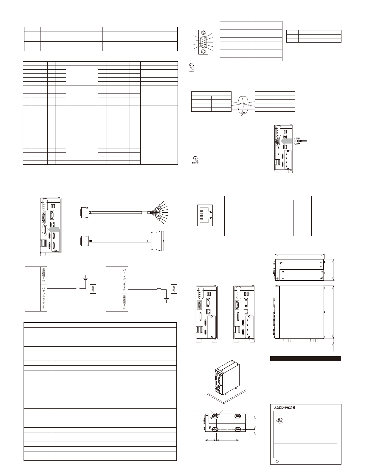
■外形寸法
■取付方法
■コントローラの仕様
●入出力コネクタ
●接続方法
●コネクタ
●コネクタ
●配線
●接続方法
NPN入出力タイプ
PNP入出力タイプ
パラレルI/Oケーブル(形FZ-VP、形FZ-VPX(別売))を最小曲げ半径以上を確保して接続します。
NPN入出力タイプ:形FZ5-L350/形FZ5-L350-10 PNP入出力タイプ:形FZ5-L355/形FZ5-L355-10
形FZ5-L350/形FZ5-L350-10
形FZ5-L355/形FZ5-L355-10
*コントローラにストロボ装置を接続したい場合に使用する信号です。カメラ2chタイプでは、STGOUT0、STGOUT1の
み使用できます。
注1.線色、マークはFZ-VPに対応しています。
注2.No.はFZ-VPXの端子台番号に対応しています。
※通風経路の確保および筐体とFG間の短絡防止のため、
絶縁脚は外さずに固定してください。
ピン番号は、接続する外部装置の種類や機種によって異なります。お手持ちのプログラマブルコントローラや
パソコンの取扱説明書を確認してください。
項目
入力仕様
出力仕様
NPN入出力タイプ
ON時:0V短絡または1.5V以下
OFF時:開放(漏れ電流0.1mA以下)
NPNオープンコレクタ
DC24V50mAmax.残留電圧1.2V以下
PNP入出力タイプ
ON時:電源電圧短絡または電源電圧−1.5V以内
OFF時:開放(漏れ電流0.1mA以下)
PNPオープンコレクタ
DC24V50mAmax.残留電圧1.2V以下
No.
A1
A2
A3
A4
A5
A6
A7
A8
A9
A10
A11
A12
A13
A14
A15
A16
A17
A18
A19
A20
A21
A22
A23
A24
A25
信号名
空き
空き
空き
空き
空き
DI1
DI3
DI5
DI7
STGOUT1
STGOUT3
ERROR
空き
空き
空き
空き
空き
DO1
DO3
DO5
DO7
DO9
DO11
DO13
空き
線色
橙
灰
白
黄
桃
橙
灰
白
黄
桃
橙
灰
白
黄
桃
橙
灰
白
黄
桃
橙
灰
白
黄
桃
線色
橙
灰
白
黄
桃
橙
灰
白
黄
桃
橙
灰
白
黄
桃
橙
灰
白
黄
桃
橙
灰
白
黄
桃
マーク(赤)
■
■
■
■
■
■■
■■
■■
■■
■■
■■■
■■■
■■■
■■■
■■■
■■■■
■■■■
■■■■
■■■■
■■■■
■■■■
■■■■
■■■■
■■■■
■■■■
マーク(黒)
■
■
■
■
■
■■
■■
■■
■■
■■
■■■
■■■
■■■
■■■
■■■
■■■■
■■■■
■■■■
■■■■
■■■■
■■■■
■■■■
■■■■
■■■■
■■■■
役割
コマンド入力
ストロボトリガ出力*
ストロボトリガ出力*
エラー発生時にON
データ出力
No.
B1
B2
B3
B4
B5
B6
B7
B8
B9
B10
B11
B12
B13
B14
B15
B16
B17
B18
B19
B20
B21
B22
B23
B24
B25
信号名
RESET
空き
空き
STEP0
DSA0
DI0
DI2
DI4
DI6
STGOUT0
STGOUT2
RUN
BUSY0
GATE0
OR0
READY0
DO0
DO2
DO4
DO6
DO8
DO10
DO12
DO14
DO15
役割
コントローラ再起動
計測トリガ入力
データ送信要求信号
コマンド入力
ストロボトリガ出力*
ストロボトリガ出力*
計測モード中ON
処理実行中にON
設定した出力時間中ON
総合判定結果
画像入力が許可されるときON
データ出力
コ ント ロ ー ラ コ ント ロ ー ラ
+24V
・形FZ-VP(2m、5m、最小曲げ半径75mm)
・形FZ-VPX(2m、5m、最小曲げ半径75mm)
0V
DC24V電源
各入力信号
各出力信号
電源端子台
パラレルコネクタ
負荷
+24V
0V
DC24V電源
各入力信号
各出力信号
電源端子台
パラレルコネクタ
負荷
電源を切った状態でケーブルを着脱してください。
周辺機器の破損の原因になります。
コネクタの向きを合わせ、まっすぐに差込み、
コネクタの両端のねじで固定してください。
使用するケーブルの最小曲げ半径以上を確保して
接続して下さい。
RJ45 8ピンモジュラコネクタ
1000BASE-Tで接続する場合は、カテゴリー5e以上の
LANケーブルを使用してください。
182.3
51
4-M4深さ6.5 絶縁脚
100
5910.5
形FZ5-L350
形FZ5-L355
形FZ5-L350-10
形FZ5-L355-10
8019712
1
2
3
4
5
6
7
8
9
シールドされたケーブルを使用してください。
適合するコネクタをご用意ください。
・推奨品
ピン番号
1
2
3
4
5
6
7
8
9
信号名
NC
SD
RD
NC
NC
NC
NC
NC
GND
役割
無接続
送信データ用
受信データ用
無接続
無接続
無接続
無接続
無接続
信号用接地
ピン番号
1
2
3
4
5
6
7
8
信号名
TD+
TD−
RD+
NC
NC
RD−
NC
NC
信号方向
出力
出力
入力
−
−
入力
−
−
信号名
TRD+(0)
TRD−(0)
TRD+(1)
TRD+(2)
TRD−(2)
TRD−(1)
TRD+(3)
TRD−(3)
信号方向
入出力
入出力
入出力
入出力
入出力
入出力
入出力
入出力
プラグ
フード
メーカ
オムロン(株)
オムロン(株)
形式
形XM3A-0921
形XM2S-0911
信号名
SD
RD
GND
コントローラ
・RS-232C
ピン番号
2
3
9
ピン番号
*
*
*
接続する外部装置
RS/CS制御はできません。
ケーブル長は、15m以下にしてください。
信号名
SD
RD
GND
操作
シリアル通信
ネットワーク通信
EtherNet/IP通信
パラレル入出力
モニタI/F
USBI/F
電源電圧
消費電流
(DC24V接続時)
耐ノイズ性
耐振動
耐衝撃
周囲温度範囲
周囲湿度範囲
周囲雰囲気
保護構造
ケース材質
質量
内容品
マウスなどによる操作
RS-232C準拠
Ethernet1000BASE-T/100BASE-TX/10BASE-T
Ethernetポート使用
伝送速度:100Mbps(100BASE-TX)
入力11点(RESET,STEP0,DSA0,DI0〜7)
出力26点(RUN,BUSY0,GATE0,OR0,READY0,ERROR,STGOUT0〜3,DO0〜15)
アナログRGBビデオ出力1ch(解像度1024×768)
2ch(USB1.1/2.0準拠)
DC24V(DC20.4V〜26.4V)
形FZ-S□/形FZ-S□2M/形FZ-S□5M□/形FZ-SF□/形FZ-SP□/形FZ-SH□接続時:
カメラ2chタイプ:約2.6A以下 カメラ4chタイプ:約2.9A以下
形FZ-SLC□□□/形FZ-SZC□□□接続時:
カメラ2chタイプ:約4.0A以下 カメラ4chタイプ:約5.5A以下
形FZ-SQ□□□□接続時:
カメラ2chタイプ:約4.0A以下 カメラ4chタイプ:約5.5A以下
1kV パルス立ち上がり:5ns パルス幅:50ns
バースト継続時間:15ms 周期:300ms
10〜150Hz 片振幅0.1mm(加速度最大15m/s
2
)3方向 各8分10回
150m/s2 6方向 各3回
動作時:0〜50℃
保存時:−20〜+65℃(ただし、氷結・結露しないこと)
動作時・保存時:35〜85%RH(ただし、結露しないこと)
腐食性ガスのないこと
IEC60529規格 IP20
メッキ鋼板
約1.8kg
コントローラ・・・1台
取扱説明書・・・和文、英文 各1枚
100BASE-TX/10BASE-T 1000BASE-T
ご使用に際してのご承諾事項
インダストリアルオートメーションビジネスカンパニー
①安全を確保する目的で直接的または間接的に人体を検出する用途に、本製品を使用
しないでください。同用途には、当社センサカタログに掲載している安全センサをご使用
ください 。
②下記用途に使用される場合、当社営業担当者までご相談のうえ仕様書などによりご確
認いただくとともに、定格・性能に対し余裕を持った使い方や、万一故障があっても危
険を最小にする安全回路などの安全対策を講じてください。
a)屋外の用途、潜在的な化学的汚染あるいは電気的妨害を被る用途
またはカタログ、取扱説明書等に記載のない条件や環境での使用
b)原子力制御設備、焼却設備、鉄道・航空・車両設備、医用機械、娯楽機械、
安全装置、および行政機関や個別業界の規制に従う設備
c)人命や財産に危険が及びうるシステム・機械・装置
d)ガス、水道、電気の供給システムや24時間連続運転システムなどの
高い信頼性が必要な設備
e)その他、上記a)〜d)に準ずる、高度な安全性が必要とされる用途
*上記は適合用途の条件の一部です。当社のベスト、総合カタログ・データシート等最新版
のカタログ、マニュアルに記載の保証・免責事項の内容をよく読んでご使用ください。
r
2012年8月
A
●その他のお問い合わせ
納期・価格・サンプル・仕様書は貴社のお取引先、または貴社
担当オムロン販売員にご相談ください。
オムロン制御機器販売店やオムロン販売拠点は、Webページで
ご案内しています。
●製品に関するお問い合わせ先
クイック オムロン
0120-919-066
■営業時間:8:00〜21:00 ■営業日:365日
●FAXやWebページでもお問い合わせいただけます。
携帯電話・PHS・IP電話などではご利用いただけませんので、下記の電話番号へおかけください。
電話
055-982-5015
(通話料がかかります)
お客様相談室
FAX055-982-5051/www.fa.omron.co.jp
Page 3

FZ5-L35□
FZ5-L35□-10
USB memory
FZ-MEM2G
FZ-MEM8G
Recommended Model
By OMRON Corporation
S8VS-12024(FZ5-L35□)
S8VS-18024(FZ5-L35□-10)
*
Camera 2ch type
FZ5-L350
FZ5-L355
Camera 4ch type
FZ5-L350-10
FZ5-L355-10
Sensor Controller
©
OMRON Corporation
2013 All Rights Reserved.
Model
INSTRUCTION SHEET
Thank you for selecting OMRON product. This sheet
primarily describes precautions required in installing and
operating the product.
Before operating the product, read the sheet thoroughly
to acquire sufficient knowledge of the product. For your
convenience, keep the sheet at your disposal.
The following notice applies only to products that carry the CE mark:
Notice:
This is a class A product. In residential areas it may cause radio
interference, in which case the user may be required to take adequate
measures to reduce interference.
Manufacturer:
Omron Corporation,
Shiokoji Horikawa, Shimogyo-ku,
Kyoto 600-8530 JAPAN
Ayabe Factory
3-2 Narutani, Nakayama-cho,
Ayabe-shi, Kyoto 623-0105 JAPAN
TRACEABILITY INFORMATION:
Representative in EU:
Omron Europe B.V.
Wegalaan 67-69
2132 JD Hoofddorp,
The Netherlands
Meanings of Signal Words
Meanings of Alert Symbols
Alert statements in this Manual
The following alert symbols are used in this manual.
The following alert statements apply to the products in this
manual. Each alert statement also appears at the locations
needed in this manual to attract your attention.
Indicates a potentially hazardous
situation which, if not avoided, will
result in minor or moderate injury, or
may result in serious injury or death.
Additionally there may be significant
property damage.
WARNING
Indicates a potentially hazardous
situation which, if not avoided, may
result in minor or moderate injury or in
property damage.
Indicates general prohibitions for which there is
no specific symbol.
Indicates the possibility of electric shock under
specific conditions.
Indicates the possibility of explosion under
specific conditions.
Indicates the possibility of laser radiation.
Indicates the possibility of injury by high
temperature under specific conditions.
CAUTION
●
Symbols and the meanings for safety precautions
described in this manual.
In order for the product to be used safely, the following
indications are used in this book to draw your attention to
the cautions. The cautions with the indications describe
the important contents for safety.
WARNING
CAUTION
This product must be used according to the
instruction manual. Failure to observe this may
result in impairment of functions and
performance of the product.
This product is not designed or rated for
ensuring safety of persons. Do not use it for
such purposes.
Never connect the AC power supply with this
product. When the AC power supply is
connected, it causes the electric shock and a fire.
A lithium battery is built into the Controller and
may occasionally combust, explode, or burn if
not treated properly. Dispose of the Controller as
industrial waste, and never disassemble, apply
pressure that would deform, heat to 100℃ or
higher, or incinerate the Controller.
Since camera that can be connected with this
product emits a visible light that may have an
adverse effect on the eyes, do not stare directly
into the light emitted from the LED. If a specular
object is used, take care not to allow reflected
light enter your eyes.
Danger of burns. Do not touch the case while the
LED is ON or just after power is turned OFF,
since it remains extremely hot.
8.5mm max. 8.5mm max.
Precautions for Safe Use
●Installation Environment
• Do not use the product in areas where flammable or explosive
gases are present.
• Install the product so that air can flow freely through its cooling
vents.
・Clean the vent regularly so as not to be clogged by dust. Clogging
of the vent may result in overheat and failure.
• Do not install the product close to high-voltage devices and power
devices in order to secure the safety of operation and
maintenance.
• Make sure to tighten all installation screws securely.
●Power Supply and Wiring
• Make sure to use the product with the power supply voltage
specified by this manual.
• Use a power supply cable and crimp terminals of the specified size.
Do not simply connect the twisted ends of the wires directly to the
terminal block.
-Applicable wire size:1.31 to 2.63mm
2
-Terminal screw:M4
-Crimp terminals
• Keep the power supply wires as short as possible (Max.10m).
• Use a DC power supply with safety measures against high-voltage
spikes(safety extra low-voltage circuits on the secondary side).
• Do the following confirmations again before turning on the power
supply.
- Is the voltage of the power supply correct? (24VDC)
- Is not the load of the output signal short-circuited?
- Is the load current of the output signal appropriate?
- Is not the mistake found in wiring?
●Ground
• Thecontrollerpowercircuitisnotinsulatedfromitsinternal
circuit.
• Besuretouseaspacerwhenconnectingacameratothe
controller.AsthehousingofthecameraistheSG(0V),itcan
causeshort-circuitingbetweentheSG(0V)andtheFGifa
spacerisnotused.
• It is short-circuited with FG of the customer device when
installing it directly because the case of the controller is
connected with SG(0V).
• Do not ground the 24VDC power supply's positive terminal. If the
positive terminal is grounded, it causes the electric shock when
you touch the SG(0V) such as case of the controller or the
camera.
●Other
• Use only the camera and cables designed specifically for the
product. Failure to observe this result in malfunction or damage of
the product.
• Always turn off the power of the sensor controller before
plugging/unplugging a camera and/or cable. Plugging a cable while
the power is on may result in a failure of a camera and/or
peripherals.
• Do not attempt to dismantle,repair,or modify the product.
• Should you notice any abnormalities,immediately stop use,turn OFF
the power supply,and contact your OMRON representative.
• Do not touch fluorescent or halogen lights while the power is ON or
immediately after the power is turned OFF.
• Dispose of this product as industrial waste.
・Do not drop the product and/or apply abnormal oscillation and/or
impact.It may result in a failure and/or burnout.
・Be careful not to drop while handling.
・A built-in lithium battery may occasionally cause severe damage
sue to fire and/or explosion.
・For the cable that is flexed repeatedly, use the robotic cable type
(flexing resistance type) to prevent damages.
・Do not apply torsion stress to the cable. It may damage the cable.
・Secure the minimum bending radius of the cable. Otherwise the
cable may be damaged.
●Regulations and Standards
The Controller complies with the following standards.
EC Directive 2004/108/EC
EN standard EN61326-1
CSA Standard CSA C22.2 No.61010-1
●Regulation of KC marking
A급 기기(업무용 방송통신기자재)
이 기기는 업무용(A급) 전자파적합기기로서 판매자
또는 사용자는 이 점을 주의하시기 바라며,가정외의
지역에서 사용하는 것을 목적으로 합니다.
Precautions for Correct Use
●Installation and Storage Sites
Install and store the product in a location that meets the
following conditions:
• Surrounding temperature of 0 to 50℃ (-20 to +65℃ in
storage)
• No rapid changes in temperature (place where dew does not
form)
• Relative humidity of between 35 to 85 %
• No presence of corrosive or flammable gases
• Place free of dust, salts and iron particles
• Place free of vibration and shock
• Place out of direct sunlight
• Place where it will not come into contact with water, oils or
chemicals
●Orientation of Product
To improve heat dissipation, install the product in the
following orientation only.
●Ambient Temperature
• Maintain a minimum clearance of 50 mm above the controller
to improve air circulation. A minimum clearance of 25 mm
between other devices must also be maintained on the right,
left and back sidesof product.
• Do not install the product immediately above significant heat
sources, such as heaters, transformers, or large-capacity
resistors.
• Do not let the ambient temperature exceed 50℃(122°F).
• Provide a forced-air fan cooling or air conditioning if the
ambient temperature is near 50℃(122°F) so that the
ambient temperature never exceeds 50℃(122°F).
●Noise Resistance
• Do not install the product in a cabinet containing high-voltage
equipment.
• Do not install the product within 200 mm of power cables.
●Component Installation and Handling
• Touching Signal Lines
To prevent damage from static electricity, use a wrist strap or
another device for preventing electrostatic discharges when
touching terminals or signal lines in connectors.
• Handling a USB Memory
To remove a USB memory, make sure that data is not being
read or written to it. The LED on the USB memory flashes
while data is being read or written, so make sure that it is lit
steadily before removing the memory.
• Turning OFF the Power
Do not turn OFF the power while a message is being
displayed indicating that processing is being performed. Data
in memory will be corrupted, and the product may not operate
correctly the next time it is started.
• Using the RESET Signal
Do not use the RESET input immediately after power is turned
ON. When using the RESET input to synchronize startup
timing,wait at least 15 second after the Controller’ s power
supply is turned ON before turning ON the RESET signal.
●Maintenance
Turn OFF the power and take safety precautions before
conducting inspections. Electrical shock can result from
attempting safety inspections with the power turned ON.
• Clean the lens with a lens-cleaning cloth or air brush.
• Lightly wipe off dirt with a soft cloth.
• Dirt on the CCD must be removed using an air brush.
• Do not use thinners or benzene.
●Communication with High-order Device
After confirming that this product is started up, communicate
with the high-order device. When this product has started up,
an indefinite signal may be output from the high-order
interface. To avoid this problem, clear the receiving buffer of
your device at initial operations.
Do not install in this orientation.
■Basic Configuration
* Items indicated with an asterisk are dedicated items, and cannot be substituted.
The Controller performs the image
processing specified by the user settings
and outputs the measurement results.
*
*
Camera cable
FZ-VS (2m, 5m,10m, min. bending radius: 69mm)
Bend resistant camera cable
FZ-VSB (2m, 5m, 10m min. bending radius: 69mm)
Right-angle camera cable
FZ-VSL (2m,5m,10m min. bending radius: 69mm)
Long-distance camera cable
FZ-VS2 (15m min. bending radius: 93mm)
Long-distance Right-angle camera cable
FZ-VSL2 (15m min. bending radius: 93mm)
Camera cable
Standalone camera
FZ-SC/FZ-S/
FZ-SC2M/FZ-S2M/
FZ-SC5M2/FZ-S5M2/
FZ-SFC/FZ-SF/
FZ-SPC/FZ-SP/
FZ-SHC/FZ-SH
Intelligent compact camera
FZ-SQ010F/FZ-SQ050F/
FZ-SQ100F/FZ-SQ100N
Intelligent camera
FZ-SLC15/FZ-SLC100
Automatic focus camera
FZ-SZC15/FZ-SZC100
Detects workpieces as images.
Camera
*
LCD monitor
Monitor cable
*
*
Use the monitor to check images and
display the condition-setting menus.
FZ-M08 (8.4-inch)
FZ-VM (2m, 5m, min. bending radius: 75mm)
Power Supply
Peripheral Device
Input Device
Mouse, track ball
(Commercially available USB devices)
This product contains a lithium battery for which the following notice applies :Perchlorate Material - special
handling may apply.
See www.dtsc.ca.gov/hazardouswaste/perchlorate
Power Supply Wiring
24VDC
+
−
●FZ5-L35□/FZ5-L35□-10
① Lit while power is ON.
② Lit while the controller is in Run Mode.
③ Lit when an error has occurred.
④ Connect the controller to external devices such as a sync sensor and PLC.
⑤ Connect cameras.
⑥ Connect a DC power supply. Wire the power supply unit independently of other devices. After wiring,
replace the terminal cover.
• The following items can be connected to USB ports. • Commercially available track ball, mause and USB memory.
• Never insert/remove USB devices during measurement. It may affect measurement time and/or destroy data.
⑦ Connect a monitor.
⑧ Connect an external device such as a personal computer or PLC.
⑨ Connect an external device such as a personal computer or PLC.
⑩Connect a mouse and USB memory, etc. Two USB ports are provided and any of them can be used.
However, when USB memory is connected with both ports, doing so may cause the USB memories to
come into contact, resulting in malfunction or damage.
①POWER LED
⑩USB connector
⑦Monitor connector (analog RGB)
⑨Ethernet connector
⑤Camera connector
Only Camera 4ch type
(FZ5 -L35□-10)
⑧RS-232C connector
⑥Power terminal
④I/O connector
(control lines, data lines)
②RUN LED
③ERROR LED
■Component Names and Functions
■U.S. California Notice:
Image Processing System
Page 4

182.3
FZ5-L350
FZ5-L355
FZ5-L350-10
FZ5-L355-10
8019712
●I/O Connector
●Connector
NPN I/O type
PNP I/O type
Connect the parallel I/O cable (FZ-VP or FZ-VPX (optional)) ensuring minimum bend radius or larger.
FZ5-L350/FZ5-L350-10
FZ5-L355/FZ5-L355-10
*In camera 2ch type, only STGOUT0 and STGOUT1 can be used.
NOTE1. The wire color and the mark correspond to FZ-VP.
NOTE2. No. corresponds to the terminal number of FZ-VPX.
Item
Input
specification
Output
specification
NPN I/O type
ON:Shorted to 0V, or 1.5V max.
OFF:Open (leakage current: 0.1mA max.)
NPN open collector
24 VDC, 50 mA max. residual voltage:1.2V max.
PNP I/O type
ON:Shorted to power supply voltage,
or power supply voltage -1.5V min.
OFF:Open (leakage current: 0.1mA max.)
PNP open collector
24 VDC, 50 mA max. residual voltage: 1.2V max.
No.
A1
A2
A3
A4
A5
A6
A7
A8
A9
A10
A11
A12
A13
A14
A15
A16
A17
A18
A19
A20
A21
A22
A23
A24
A25
Signal name
(Open)
(Open)
(Open)
(Open)
(Open)
DI1
DI3
DI5
DI7
STGOUT1
STGOUT3
ERROR
(Open)
(Open)
(Open)
(Open)
(Open)
DO1
DO3
DO5
DO7
DO9
DO11
DO13
(Open)
Wire color
Orange
Gray
White
Yellow
Pink
Orange
Gray
White
Yellow
Pink
Orange
Gray
White
Yellow
Pink
Orange
Gray
White
Yellow
Pink
Orange
Gray
White
Yellow
Pink
Wire color
Orange
Gray
White
Yellow
Pink
Orange
Gray
White
Yellow
Pink
Orange
Gray
White
Yellow
Pink
Orange
Gray
White
Yellow
Pink
Orange
Gray
White
Yellow
Pink
Mark (red)
■
■
■
■
■
■■
■■
■■
■■
■■
■■■
■■■
■■■
■■■
■■■
■■■■
■■■■
■■■■
■■■■
■■■■
■■■■
■■■■
■■■■
■■■■
■■■■
Mark (blk)
■
■
■
■
■
■■
■■
■■
■■
■■
■■■
■■■
■■■
■■■
■■■
■■■■
■■■■
■■■■
■■■■
■■■■
■■■■
■■■■
■■■■
■■■■
■■■■
Function
Command inputs
Strobe trigger output (*)
Strobe trigger output (*)
ON when there is an error.
Data output
No.
B1
B2
B3
B4
B5
B6
B7
B8
B9
B10
B11
B12
B13
B14
B15
B16
B17
B18
B19
B20
B21
B22
B23
B24
B25
Signal name
RESET
(Open)
(Open)
STEP0
DSA0
DI0
DI2
DI4
DI6
STGOUT0
STGOUT2
RUN
BUSY0
GATE0
OR0
READY0
DO0
DO2
DO4
DO6
DO8
DO10
DO12
DO14
DO15
Function
Controller restart
Measurement trigger input
Data send request signal
Command inputs
Strobe trigger output (*)
Strobe trigger output (*)
ON while in Run mode
ON during processing
ON for the set output time
Overall judgment result
ON when image input is allowed
Data output
• FZ-VP (2m, 5m, min. bending radius: 75mm)
• FZ-VPX (2m, 5m, min. bending radius: 75mm)
NPN I/O type:FZ5-L350/FZ5-L350-10 PNP I/O type:FZ5-L355/FZ5-L355-10
Controller
Parallel
connector
Parallel
connector
Power
terminal
Power
terminal
Controller
+24V
0V
■Parallel Interface
Each output signal
Each output signal
Each input signal
Each input signal
+24V
0V
24 VDC
24 VDC
Load Load
●Connector
●Wiring
●Connection Method
Pin numbers will depend on the external device being connected. Refer to the manual for the personal
computer or PLC being connected.
1
2
3
4
5
6
7
8
9
Useashieldedcable.
Use a compatible connector.
• Recommended items
Pin No.
1
2
3
4
5
6
7
8
9
Signal name
NC
SD
RD
NC
NC
NC
NC
NC
GND
Function
Not connected
For RS-232C
For RS-232C
Not connected
Not connected
Not connected
Not connected
Not connected
Signal ground
Plug
Hood
Manufacturer
OMRON Corporation
OMRON Corporation
Model
XM3A-0921
XM2S-0911
Controller
• RS-232C
PinNo.
2
3
9
PinNo.
*
*
*
Externaldevicetobeconnected
RS/CScontrolcannotbeused.
The maximum cable length is 15m.
Signalname
SD
RD
GND
Signalname
SD
RD
GND
Align the connector with the socket and press it
straight into place, then fix it with the screws on
both sides of the connector.
Connect the cable ensuring the minimum bend
radius or larger.
Turn OFF the power supply before connecting or
disconnecting a Parallel I/O Cable. Peripheral
devices may be damaged if the cable is connected
or disconnected with the power ON.
■Serial Interface
■Ethernet interface
●Connector
RJ45 8-pin modular connector
Use LAN cable of category 5e or more when connecting it with 1000BASE-T.
Pin No.
1
2
3
4
5
6
7
8
Signal name
TD+
TD−
RD+
NC
NC
RD−
NC
NC
Signal direction
Out
Out
In
−
−
In
−
−
Signal name
TRD+(0)
TRD−(0)
TRD+(1)
TRD+(2)
TRD−(2)
TRD−(1)
TRD+(3)
TRD−(3)
Signal direction
In/Out
In/Out
In/Out
In/Out
In/Out
In/Out
In/Out
In/Out
100BASE-TX/10BASE-T 1000BASE-T
■Dimensions
■Mounting
*Fix without removing the insulation leg because neither
the ventilation route is closed nor the case are connected
with FG.
51
4-M4 DEPTH6.5 INSULATION LEG
100
5910.5
Operation
Serial communications
Network communications
EtherNetI/P communications
Parallel I/O
Monitor interface
USB interface
Power supply voltage
Current consumption
(At Power supply voltage 24VDC)
Noise resistance
Vibration resistance
Shock resistance
Ambient temperature range
Ambient humidity range
Ambient environment
Degree of protection
Environmental conditions
(according to IEC61010-1)
Case materials
Weight
Content goods
Mouse or similar device
RS-232C
Ethernet 1000BASE-T/100BASE-TX/10BASE-T
Used Ethernet port
Transmission speed:100Mbps(100BASE-TX)
11 inputs (RESET, STEP0,DSA0,DI0 to 7)
26 outputs (RUN,BUSY0,GATE0,OR0,READY0,ERROR,STGOUT0 to 3, DO0 to 15)
Analog RGB video output 1 channel (Resolusion: XGA 1024×768)
2 channels (supports USB1.1 and 2.0)
24 V DC (20.4 to 26.4 V DC)
Consumption of current varies depending on the type of camera connected.
When FZ-S□/FZ-S□2M/FZ-S□5M□/FZ-SF□/FZ-SP□/FZ-SH□ is connected:
Camera 2ch type:Approx. 2.6A max. Camera 4ch type:Approx. 2.9A max.
When FZ-SLC□□□/FZ-SZC□□□ is connected:
Camera 2ch type:Approx. 4.0A max. Camera 4ch type:Approx. 5.5A max.
When FZ-SQ□□□□ is connected:
Camera 2ch type:Approx. 4.0A max. Camera 4ch type:Approx. 5.5A max.
1 kV, pulse rise: 5 ns Pulse width: 50 ns
Burst continuing time: 15 ms Cycle: 300 ms
10 to 150 Hz, one-side amplitude 0.1 mm (Max. acceleration 15m/s2)
10 times for 8 minutes for each three direction
150 m/s2; 3 times each in 6 directions
Operating: 0 to 50 °C (with no icing nor no condensation)
Storage: –20 to +65 °C (with no icing nor no condensation)
Operating and storage: 35 % to 85 % (no condensation)
No corrosive gases
IEC60529 IP20
Indoor use
Maximum altitude of 2,000m
Supply voltage fluctuations of +10 %, –15 % of the rated voltage
Installation category I
Pollution degree 2
Plating steel board
Approx. 1.8 kg
Controller ・ ・ ・ Qty:1
Instruction Manual ・ ・ ・ Qty:1 piece for each Japanese and English
■Controller Specifications
OMRON Corporation
Suitability for Use
EUROPE
OMRON EUROPE B.V. Sensor Business Unit
Carl-Benz Str.4, D-71154 Nufringen Germany
Phone:49-7032-811-0 Fax: 49-7032-811-199
NORTH AMERICA
OMRON ELECTRONICS LLC
One Commerce Drive Schaumburg,IL 60173-5302 U.S.A.
Phone:1-847-843-7900 Fax : 1-847-843-7787
ASIA-PACIFIC
OMRON ASIA PACIFIC PTE. LTD.
No. 438A Alexandra Road #05-05-08(Lobby 2),
Alexandra Technopark, Singapore 119967
Phone : 65-6835-3011 Fax :65-6835-2711
THE PRODUCTS CONTAINED IN THIS SHEET ARE NOT SAFETY RATED.
THEY ARE NOT DESIGNED OR RATED FOR ENSURING SAFETY OF
PERSONS, AND SHOULD NOT BE RELIED UPON AS A SAFETY
COMPONENT OR PROTECTIVE DEVICE FOR SUCH PURPOSES.
Please refer to separate catalogs for OMRON's safety rated products.
OMRON shall not be responsible for conformity with any standards, codes,
or regulations that apply to the combination of the products in the
customer's application or use of the product.
Take all necessary steps to determine the suitability of the product for the
systems, machines, and equipment with which it will be used.
Know and observe all prohibitions of use applicable to this product.
NEVER USE THE PRODUCTS FOR AN APPLICATION INVOLVING SERIOUS
RISK TO LIFE OR PROPERTY WITHOUT ENSURING THAT THE SYSTEM AS
A WHOLE HAS BEEN DESIGNED TO ADDRESS THE RISKS, AND THAT
THE OMRON PRODUCT IS PROPERLY RATED AND INSTALLED FOR THE
INTENDED USE WITHIN THE OVERALL EQUIPMENT OR SYSTEM.
See also Product catalog for Warranty and Limitation of Liability.
CHINA
OMRON(CHINA) CO., LTD.
Room 2211, Bank of China Tower,
200 Yin Cheng Zhong Road,
PuDong New Area, Shanghai, 200120, China
Phone : 86-21-5037-2222 Fax :86-21-5037-2200
OCT. 2009
D
 Loading...