

Page 1
Vision Sensor
FH/FHV/FZ5 Series
Vision System
User’s Manual
FH-1/FH-1-
FH-2/FH-2-
FH-3/FH-3-
FH-5/FH-5-
FH-L/FH-L-
FHV7-
FZ5-6/FZ5-6-
FZ5-8/FZ5-8-
FZ5-11/FZ5-11-
FZ5-12/FZ5-12-
FZ5-L35/FZ5-L35-
Z365-E1-05
Page 2

NOTE
• All rights reserved. No part of this publication may be reproduced, stored in
a retrieval system, or transmitted, in any form, or by any means, mechanical,
electronic, photocopying, recording, or otherwise, without the prior written
permission of OMRON.
• No patent liability is assumed with respect to the use of the information
contained herein. Moreover, because OMRON is constantly striving to improve
its high-quality products, the information contained in this manual is subject
to change without notice. Every precaution has been taken in the preparation of
this manual. Nevertheless, OMRON assumes no responsibility for errors or omis
sions. Neither is any liability assumed for damages resulting from the use of
the information contained in this publication.
Trademarks
•
Sysmac and SYSMAC are trademarks or registered trademarks of OMRON Corporation
in Japan and other countries for OMRON factory automation products.
•
This software is based in part on the work of the Independent JPEG Group.
Microsoft, Windows, Windows Vista, Excel, and Visual Basic are either registered trade-
•
marks or trademarks of Microsoft Corporation in the United States and other countries.
Intel, Core and Pentium are trademarks of Intel Corporation in the U.S. and/or other
•
countries.
EtherCAT® is registered trademark and patented technology, licensed by Beckhoff
•
Automation GmbH, Germany.
•
ODVA, CIP, CompoNet, DeviceNet, and EtherNet/IP are trademarks of ODVA.
The SD, SDHC, microSD, and microSDHC logos are trademarks of SD-3C, LLC.
•
QR Code is a registered trademark of DENSO WAVE INCORPORATED.
•
•
MELSEC is a registered trademarks of Mitsubishi Electric Corporation.
Other company names and product names in this document are the trademarks
or registered trademarks of their respective companies.
Copyrights
Microsoft product screen shots reprinted with permission from Microsoft Corporation.
Page 3

Introduction
Thank you for purchasing the FH/FHV/FZ5.
This manual provides information regarding functions, performance and operating methods that are
required for using the FH/FHV/FZ5.
When using the FH/FHV/FZ5, be sure to observe the following:
• The FH/FHV/FZ5 must be operated by personnel knowledgeable in electrical engineering.
• To ensure correct use, please read this manual thoroughly to deepen your understanding of
the product.
• Please keep this manual in a safe place so that it can be referred to whenever necessary.
Introduction
Vision System FH/FHV/FZ5 Series User’s Manual (Z365)
1
Page 4

Related Manuals
Related Manuals
The followings are the manuals related to this manual. Use these manuals for reference.
Name of Manual Man.No. Model Proposes Contents
Vision System FH
Instruction Sheet
Vision System FH
Instruction Sheet
Vision System FH-L
Instruction Sheet
Vision System FZ5
Instruction Sheet
Vision System FZ5
Instruction Sheet
Vision System
FZ5-L Instruction
Sheet
Smart Camera
FHV Instruction
Sheet
Smart Camera
Lighting Module
FHV-LTM
Instruction Sheet
Smart Camera Lens
Module FHV-LEM-S
Instruction Sheet
FHV Series
Smart Camera
Setup Manual
9607479-9 FH-1
FH-1-
FH-3
FH-3-
3102269-4 FH-2
FH-2-
FH-5
FH-5-
9606631-1 FH-L
FH-L-
9524422-4 FZ5-6
FZ5-6-
FZ5-11
FZ5-11-
9308317-7 FZ5-8
FZ5-8-
FZ5-12
FZ5-12-
9910002-2 FZ5-L35
FZ5-L35-
3129404-0 FHV7--C To confirm the safety and
3129276-4 FHV-LTM To confirm the safety and
3128622-5 FHV-LEM-S To confirm the safety and
Z408 FHV7--C
FHV7--S-
FHV7--S--
To confirm the safety and
usage precautions of the
Vision System FH series
Sensor Controller.
To confirm the safety and
usage precautions of the
Vision System FH-Lite
series Sensor Controller.
To confirm the setup
procedures, safety and
usage precautions of the
Vision System FZ5-600,
FZ5-1100 series Sensor
Controller, including I/O
setup and wiring
To confirm the setup
procedures, safety and
usage precautions of the
Vision System
FZ5-800,FZ5- 1200 series
Sensor Controller,
including I/O setup and
wiring
o confirm the setup
T
procedures, safety and
sage precautions of the
u
Vision System FZ5-L
Series Sensor Controller,
including I/O setup and
wiring.
usage precautions of the
Smart Camera FHV
series.
usage precautions of the
Smart camera lighting
module FHV-LTM.
usage precautions of the
Smart camera lens
module FHV-LEM.
When User want to know
about the hardware
specifications or to setup
the Smart camera FHV
series.
Describes the definitions of basic
terms, meaning of signal words,
and precautions for correct use of
FH series in the manual.
Describes the definitions of basic
terms, meaning of signal words,
and precautions for correct use of
FH-L series in the manual.
Describes the definitions of basic
terms, meaning of signal words,
and precautions for correct use of
FZ5-600, FZ5-1100 series in the
manual.
Describes the definitions of basic
terms, meaning of signal words,
and precautions for correct use of
FZ5-800, FZ5-1200 series in the
manual.
Describes the definitions of basic
terms, meaning of signal words,
and precautions for correct use of
FZ5-L series in the manual.
Describes the definitions of basic
terms, the meaning of signal
words, and precautions for
correct use of FHV series in the
manual.
Describes the definitions of basic
terms, the meaning of signal
words, and precautions for
correct use of the lighting module
FHV-LTM in the manual.
Describes the definitions of basic
terms, the meaning of signal
words, and precautions for
correct use of the lens module
FHV-LEM.
Describes FHV series
specifications, dimensions, part
names, I/O information,
installation information, and
wiring information.
2
Vision System FH/FHV/FZ5 Series User’s Manual (Z365)
Page 5

Related Manuals
Name of Manual Man.No. Model Proposes Contents
Vision System
FH/FHV/FZ5 Series
User’s
Manual
Vision System
FH/FZ5 series
Processing Item
Function Reference
Manual
Vision System
FH/FZ5 Series
User’s Manual for
Communications
gs
Settin
Vision System
FH/FZ5 series
Macro Customize
Functions
Programming
Manual
Vision System
FH/FZ5 series
Hardware Setup
Manual
Vision System FH
Series Operation
Manual for Sysmac
Studio
Z365 FH-1
FH-1-
FH-2
FH-2-
Z341 When User confirm the
Z342 When User
Z367 FH-1
Z366 When User want to know
Z343 FH-1
FH-3
FH-3-
FH-5
FH-5-
FH-L
FH-L-
FHV7--C
FHV7--S-
FHV7--S--
FZ5-L35
FZ5-L35-
FZ5-6
FZ5-6-
FZ5-8
FZ5-8-
FZ5-11
FZ5-11-
FZ5-12
FZ5-12-
FH-1-
FH-2
FH-2-
FH-3
FH-3-
FH-5
FH-5-
FH-L
FH-L-
FZ5-L35
FZ5-L35-
FZ5-6
FZ5-6-
FZ5-8
FZ5-8-
FZ5-11
FZ5-11-
FZ5-12
FZ5-12-
FH-1FHFH-2
FH-3
FH-3-
FH-5
FH-5-
2
-
When User want to know
how to setup the Sensor
Controller of the Vision
System FH/FZ5 series.
details of each processing
items at the create the
measurement flow or
operate it.
confirm the
setting of communication
functions.
When User operate or
programming using Macro
Customize functions.
about the Hard-ware
specifications or to setup
the Sensor Controller of
the Vision System FH/FZ5
series.
When User connect to NJ
series via EtherCAT
communication.
Describes the soft functions,
setup, and operations to use
Sensor Controller of the Vision
System FH/FZ5 series.
Describes the software functions,
settings, and operations for using
FH/FHV/FH5-series.
Describes the functions, settings,
and communications methods for
communicating between
FH/FHV/FH5 series.
The following communication
protocol are described.
Parallel, PLC Link, EtherNet/IP,
EtherCAT, and Non-procedure
Describes the functions, settings,
and operations for using Macro
Customize function of the
FH/FH5-series.
Describes FH/FZ5 series
specifications, dimensions, part
names, I/O information,
installation information, and
wiring information.
Describes the operating
procedures for setting up and
operating FH series Vision
Sensors from the Sysmac Studio
FH Tools.
Vision System FH/FHV/FZ5 Series User’s Manual (Z365)
3
Page 6
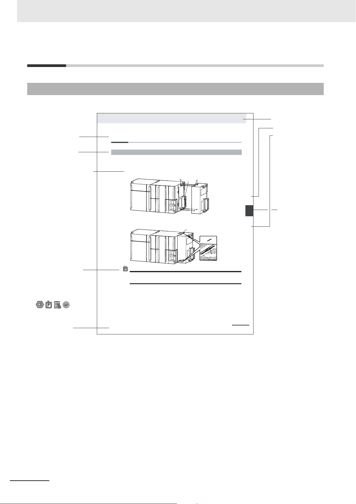
Manual Structure
4-9
4 Installation and Wiring
NJ-series CPU Unit Hardware User’s Manual (W500)
stinU gnitnuoM 3-4
4
stnenopmoC rellortnoC gnitcennoC 1-3-4
4-3 Mounting Units
The Units that make up an NJ-series Controller can be connected simply by pressing the Units together
and locking the sliders by moving them toward the back of the Units. The End Cover is connected in the
same way to the Unit on the far right side of the Controller.
1 Join the Units so that the connectors fit exactly.
2 T he yellow sliders at the top and bottom of each Unit lock the Units together. Move the sliders
toward the back of the Units as shown below until they click into place.
Precautions for Correct UsePrecautions for Correct Use
4-3-1 Connecting Controller Components
Connector
Hook
Hook holes
Slider
Lock
Release
Move the sliders toward the back
until they lock into place.
Level 1 heading
Level 2 heading
Level 3 heading
Level 2 heading
A step in a procedure
Manual name
Special information
Level 3 heading
Page tab
Gives the current
headings.
Indicates a procedure.
Icons indicate
precautions, additional
information, or reference
information.
Gives the number
of the main section.
This illustration is provided only as a sample. It may not literally appear in this manual.
The sliders on the tops and bottoms of the Power Supply Unit, CPU Unit, I/O Units, Special I/O
Units, and CPU Bus Units must be completely locked (until they click into place) after connecting
the adjacent Unit connectors.
Manual Structure
Page Structure
The following page structure and icons are used in this manual.
4
Vision System FH/FHV/FZ5 Series User’s Manual (Z365)
Page 7

Precautions for Safe UsePrecautions for Safe Use
Precautions for Correct Use
Additional Information
Version Information
Special Information
Special information in this manual is classified as follows:
Precautions on what to do and what not to do to ensure safe usage of the product.
Precautions on what to do and what not to do to ensure proper operation and performance.
Additional information to read as required.
This information is provided to increase understanding or make operation easier.
Manual Structure
Information on differences in specifications and functionality for CPU Units and EtherCAT Coupler Units with different unit versions and for different versions of the Sysmac Studio is given.
Note References are provided to more detailed or related information.
Vision System FH/FHV/FZ5 Series User’s Manual (Z365)
5
Page 8

Manual Structure
Conventions Used in This Manual
• Use of Quotation Marks and Brackets
In this manual, menus and other items are indicated as follows.
[]
“”
Menu Indicates the menu names or processing items shown in the menu bar.
Item name Indicates the item names displayed on the screen.
6
Vision System FH/FHV/FZ5 Series User’s Manual (Z365)
Page 9

Definitions of Basic Terms
Ter m Definition
FH Series All FH series model names as follows:
FH-1, FH-1-, FH-2, FH-2-, FH-3,
FH-3-, FH-5, FH-5-, FH-L, FH-L-
FH-1000 series All FH-1 series model names as follows:
FH-1, FH-1-
FH-2000 series All FH-2 series model names as follows:
FH-2, FH-2-
FH-3000 series All FH-3 series model names as follows:
FH-3, FH-3-
FH-5000 series All FH-5 series model names as follows:
FH-5, FH-5-
FH-L series All FH-L series model names as follows:
FH-L, FH-L-
FZ5 series All FZ series name shows the following:
FZ5-6, FZ5-6-, FZ5-8, FZ5-8-, FZ5-11, FZ5-11-,
FZ5-12, FZ5-12-, FZ
FZ5-600 series All FZ5-6series name the following:
FZ5-6, FZ5-6-
FZ5-800 series All FZ5-8series name the following:
FZ5-8, FZ5-8-
FZ5-1100 series All FZ5-11series name the following:
FZ5-11, FZ5-11-
FZ5-1200 series All FZ5-12series name the following:
FZ5-12, FZ5-12-
FZ5-L series All FZ5-L35 series name the following:
FZ5-L35, FZ5-L35-
Sensor Controller It is a generic name of FH/FZ5 series. For FHV series, it has the same meaning as
smart camera.
measurement flow
(abbreviated as “flow”)
measurement processing
Measurement ID Information of time when the sensor controller receives the measurement trigger and
A continuous flow of measurement processing. A measurement flow consists of a
scene created from a combination of processing items.
Executing processing items for inspections and measurements.
the line no.
Format of measurement ID: YYYY-MM-DD_HH-MM-SS-XXXX
YYYY: Year (4 digits)
MM: Month
DD: Date
HH: Hour
MM: Minute
SS: Second
XXXX: Millisecond
Example:
Measured time: 12/24/2007, 11:10:25.500:
Line: 0
Measurement ID: 2007-12-24_11-10-25-5000
5-L35, FZ5
Definitions of Basic Terms
-L35-
Vision System FH/FHV/FZ5 Series User’s Manual (Z365)
7
Page 10

Definitions of Basic Terms
Ter m Definition
processing item Any of the individual items for vision inspections that are partitioned and packaged so
scene A unit for changing the measurement flow that consists of a combination of processing
processing unit (abbreviated as “unit”)
measurement trigger A trigger for executing measurements.
test measurement A measurement that is performed to manually test (check) measurements under the
single measurement A measurement that is executed only once in synchronization with the trigger input.
continuous measurement
that they can be flexibly combined.
These include the Search, Position Compensation, and Fine Matching items.
Processing items can be classified for image input ([Input image]), inspection/measurement ([Measurement]), image correction ([Compensate image]), inspection/measurement support ([Support measurement]), process branching ([Branch]), results
external output ([Output result]), resulting image display ([Display result]), etc.
You can freely classify processing items to handle a wide range of applications.
A scene (i.e., a unit for changing the measurement flow) is created by registering the
processing items as units.
items.
“Scene” is used because of the correspondence to the scene (i.e., type of measurement object and inspection contents) where measurements are performed.
A scene is created for each measurement or measurement contents.
You can easily achieve a changeover simply by changing the scene when the measurement object or inspection content changes.
Normally you can set up to 128 scenes. If you need more than 128 scenes, you can
separate them into different groups or use the Conversion Scene Group Data Tool to
create a scene group that contains over 128 scenes.
A processing item that is registered in a scene.
Numbers are assigned to processing units in order from the top and they are executed
in that order.
Processing items are registered for the processing units to create a scene (i.e., a unit
for changing the measurement flow).
With a parallel interface, the STEP signal or command 00 (Continuous Measurement)
is used. With a serial interface, an Execute One Measurement or a Start Continuous
Measurement command is used.
conditions that are set in the currently displayed scene.
Test measurements can be executed on an Adjustment Window. Processing is completed inside the Controller and the measurement results are not normally output on
an external interface.
However, you can select [Output] in [Test measurement] to output the measurement
results after executing measurements.
Measurements are executed repeatedly and automatically without a trigger input.
8
Vision System FH/FHV/FZ5 Series User’s Manual (Z365)
Page 11

Definitions of Basic Terms
Ter m Definition
operation
modes
parallel processing (an
option for any of the
above operation
modes)
multi-input function A function that is used to consecutively and quickly input images.
Double
Speed
Multi-input
Multi-line
Random-trigger
Non-stop
Adjustment
Standard A logging mode that allows complete parallel processing of measurements and log-
A mode that processes the measurement flow for the first trigger and then processes
the measurement flow in parallel for the second trigger to achieve a high-speed trigger
input interval. It is used together with the multi-input function.
A trigger mode that allows you to independently processing multiple measurement
flows.
With traditional image processing, two or more triggers cannot be acknowledged at the
same time.
In Multi-line Random-trigger Mode, you can randomly input multiple triggers into one
Controller to independently process multiple scenes in parallel.
A mode that allows you to adjust the flow and set parameters while performing measurements.
The enables adjustments without stopping the line or stopping inspections.
ging.
Traditionally, logging was not possible while processing measurements. Either measurements or logging had to be given priority and the other one had to wait.
With this mode, you can save the measurement images in external storage without
affecting the transaction time.
Parallel processing splits part of the measurement flow into two or more tasks, and
processes each task in parallel to shorten the transaction time.
Processing items for parallel processing are used so that the user can specify the
required parallel processing.
It allows the next STEP signal to be acknowledged as soon as the image input processing is completed. There is no need to wait for measurement processing to be
completed.
You can check whether image input processing has been completed with the status of
the READY signal. Even if the READY signal is ON when measurement processing is
being executed, the next STEP signal can be acknowledged.
Vision System FH/FHV/FZ5 Series User’s Manual (Z365)
9
Page 12
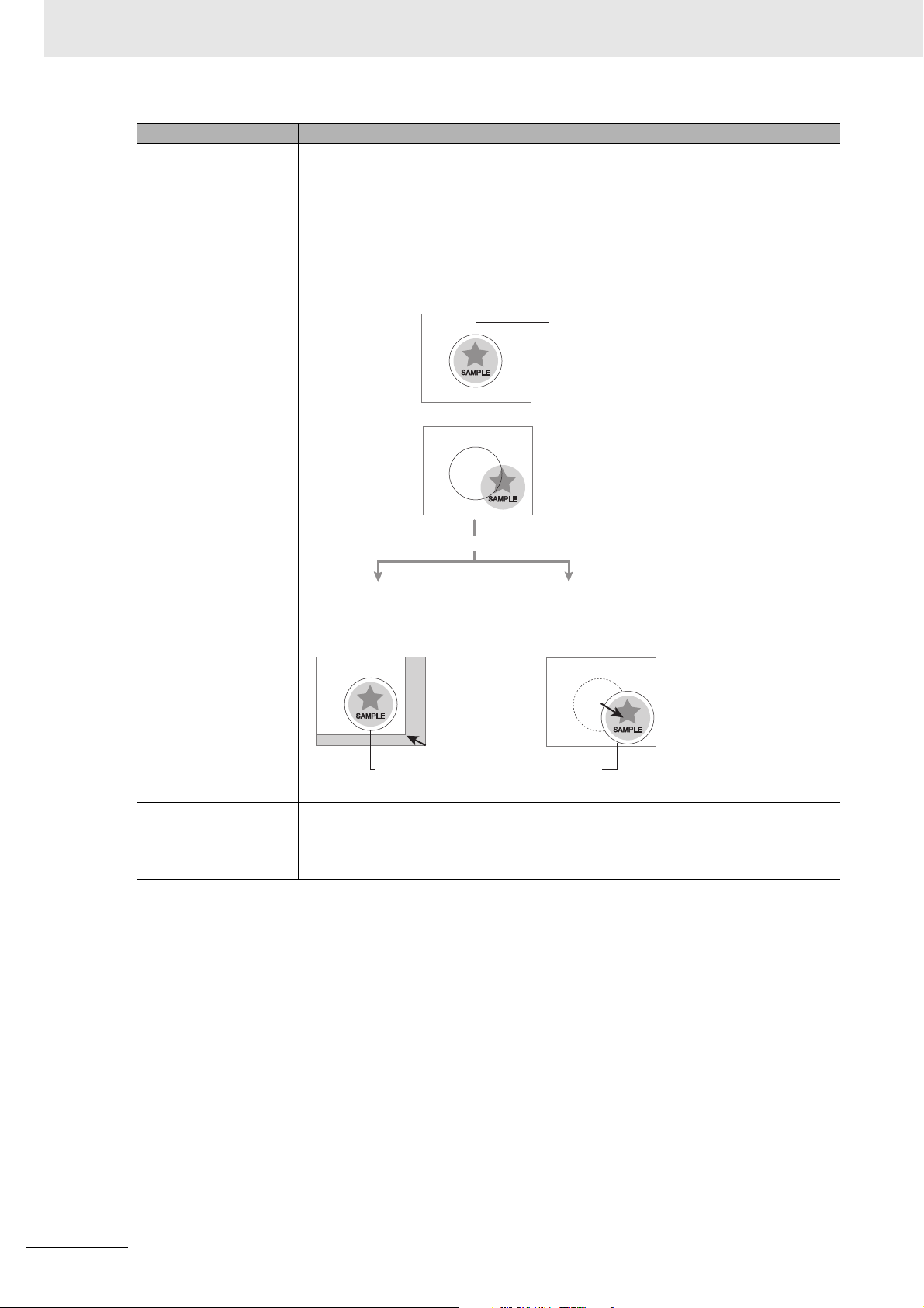
Definitions of Basic Terms
When position of object to be measured is deflected
When position deflection correction is set in advance:
Object to be measured
overflows Measurement area.
Reference position
Measurement area and objects to be measured
are correctly aligned.
Object to be measured
Measurement area
Measurement will be carried out
after measured object enters into Measurement area.
Measurement will be carried out after
moving the Measurement area for a
corresponding deflection.
Measurement will be carried out
after moving the image for a
corresponding deflection and
returning to the reference position.
Ter m Definition
Position compensation When the location and direction of measured objects are not fixed, the positional devi-
ation between reference position and current position is calculated and measurement
is performed after correcting.
Please select processing items that are appropriate to the measurement object from
processing items that are related to position compensation.
Reference position The point that is always the reference. If the location of the registered model is differ-
Model The image pattern that serves as the inspection target. Characteristics portions are
ent from the reference position, the setting should be changed in [Ref. setting].
extracted from images of the object and registered as model registration.
10
Vision System FH/FHV/FZ5 Series User’s Manual (Z365)
Page 13
Definitions of Basic Terms
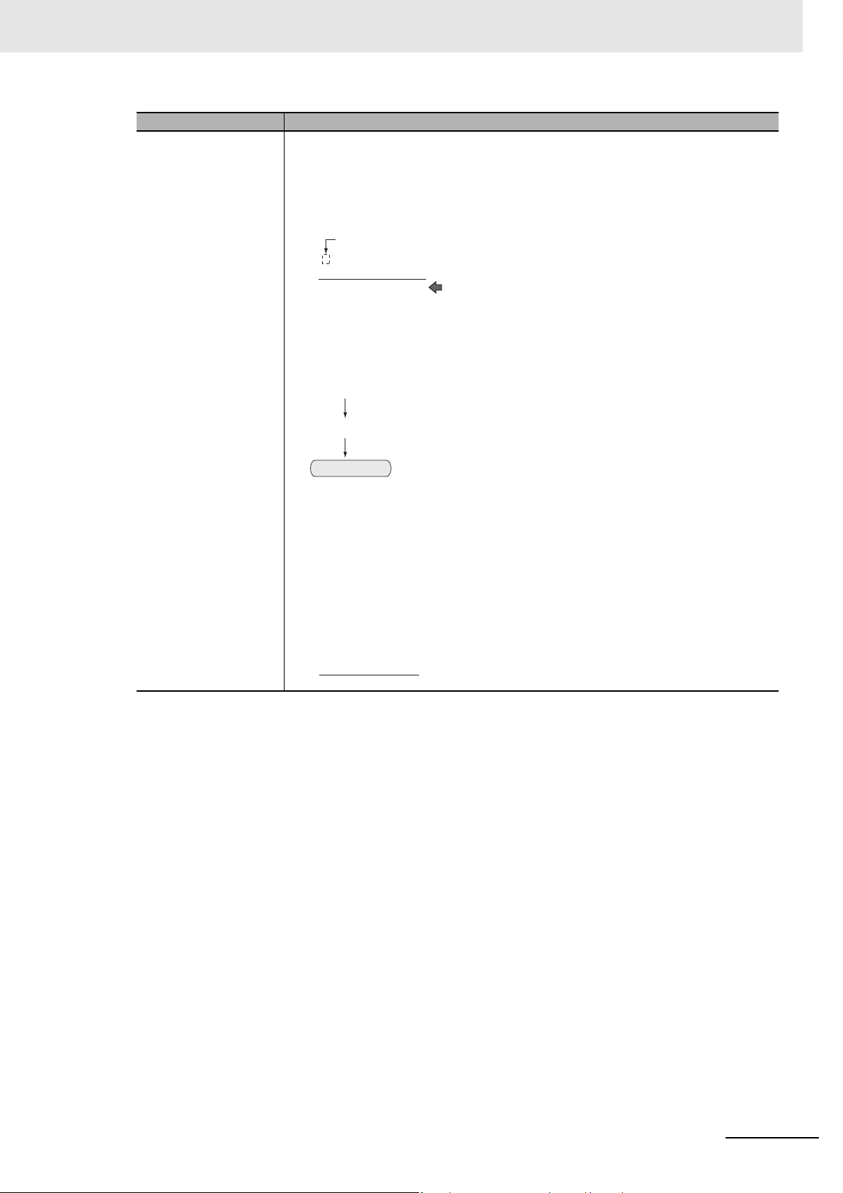
−“1” is expresses with 2’s Complement (for 8 bits)
00000000 (= 0)
−
)
(In the case of 1, minus 1)
00000001 (= 1)
11111111 (=−1)
1
1111111 (= −1)
00001001 (= 9)
+)00001010 (= 10)
Ter m Definition
2's complement Binary numbers are generally used to represent negative numbers.
Negative numbers are expressed by "Inverting all bits of a positive number and adding
1 to the result".
(Example) "−1" is expressed as 2's complement
"−1" can be calculated by "0-1".
There are methods for simple calculation without performing this kind of computation.
For instance, "Negative number = inverting all bits of a positive number and then adding 1 to the result".
00000001 (= 1)
Invert all bits
11111110
Plus 1
11111111 (=−1)
The first digit is used to judge whether the number is positive or negative.
When 0: Positive number (or 0)
When 1: Negative number
The advantage of two's complement numbers is that positive and negative numbers
can be used as is in calculations.
(Example) When −1+10=9
Vision System FH/FHV/FZ5 Series User’s Manual (Z365)
11
Page 14

Definitions of Basic Terms
12
Vision System FH/FHV/FZ5 Series User’s Manual (Z365)
Page 15

1
2
3
4
5
1 9
2 10
3
4
5 I
8
Creating
Measurement
Scenes
8
6
7
6
7
11
A
9
10
11
A
I
Overview
Features
Basic
Operations
Using Tools
Performing Measurement and Adjustment
Increasing/Switching Measurement Scenes
Setting Windows
Saving/
Loading Data
Advanced Usage
What to Do!
Appendices
Index
Sections in this Manual
Sections in this Manual
Vision System FH/FHV/FZ5 Series User’s Manual (Z365)
13
Page 16

CONTENTS
CONTENTS
Introduction ..............................................................................................................1
Related Manuals .......................................................................................................2
Manual Structure ......................................................................................................4
Page Structure............................................................................................................................................. 4
Special Information...................................................................................................................................... 5
Conventions Used in This Manual............................................................................................................... 6
Definitions of Basic Terms ......................................................................................7
Sections in this Manual .........................................................................................13
CONTENTS..............................................................................................................14
Terms and Conditions Agreement ........................................................................22
Warranty, Limitations of Liability ................................................................................................................ 22
Safety Precautions .................................................................................................24
Precautions for Safe Use.......................................................................................26
Precautions for Correct Use.................................................................................. 31
Regulations and Standards...................................................................................37
All Series.................................................................................................................................................... 37
FH-1000/2000/3000/5000 series ............................................................................................................... 37
FH-L series ................................................................................................................................................ 38
FHV series................................................................................................................................................. 39
FZ5 series/FZ5-L series............................................................................................................................. 39
Revision History .....................................................................................................40
Section 1 Overview
1-1 Checking the System Configuration.................................................................................... 1-2
1-1-1 System Configuration..................................................................................................................1-2
1-1-2 Functional Comparison between the FH-series, FHV-series and FZ5-series Controllers........... 1-3
1-2 Flow of Application ............................................................................................................... 1-7
Section 2 Features
2-1 Basic Mechanism for Measurements................................................................................... 2-2
2-2 Support for a Variety of Scenes and Measurement Lines ................................................. 2-4
Section 3 Basic Operations
3-1 Preparing the Controller and Cameras................................................................................ 3-2
3-1-1 Camera Setup.............................................................................................................................3-2
3-1-2 Preparing a Controller................................................................................................................. 3-4
3-1-3 Adjusting the Camera.................................................................................................................. 3-5
14
Vision System FH/FHV/FZ5 Series User’s Manual (Z365)
Page 17

CONTENTS
3-2 Basic Knowledge about Operations .................................................................................... 3-6
3-2-1 Inputting Values .......................................................................................................................... 3-6
3-2-2 Inputting Text .............................................................................................................................. 3-7
3-2-3 Selecting Files and Folders ...................................................................................................... 3-10
3-2-4 Available Operations in Select File Window ............................................................................. 3-13
3-2-5 Using the Zoom Function.......................................................................................................... 3-14
3-2-6 Setting Figures.......................................................................................................................... 3-15
3-2-7 Changing the Image Mode and Other Display Contents .......................................................... 3-24
3-2-8 Changing the Display Ratio ...................................................................................................... 3-25
3-3 Checking System Information............................................................................................ 3-27
3-4 Checking the Memory Consumption and Percentage of Memory Used ........................ 3-31
3-5 Capturing Screen Images ................................................................................................... 3-32
3-6 Saving Settings before Turning OFF the Power and Restarting ..................................... 3-34
3-6-1 Saving the Setting to the Controller [Data Save] ...................................................................... 3-34
3-6-2 Device Information Storage Tool............................................................................................... 3-35
3-6-3 Restarting the Controller: [System Restart] .............................................................................. 3-37
3-7 Initializing the Controller .................................................................................................... 3-39
3-8 Turning OFF the LCD ..........................................................................................................3-41
3-8-1 Turning OFF the LCD [LCD OFF]............................................................................................. 3-41
3-8-2 Restoring Power to the LCD..................................................................................................... 3-41
Section 4 Setting the Controller
4-1 Selecting Language [Startup Settings]................................................................................ 4-2
4-2 Setting the Status at Startup [Startup Settings].................................................................. 4-3
4-3 Setting Communication [Startup Settings] ......................................................................... 4-6
4-4 Setting Operation Mode [Startup Settings]....................................................................... 4-12
4-4-1 Setting the Operation Mode...................................................................................................... 4-13
4-4-2 Parallel Processing................................................................................................................... 4-29
4-5 Checking the Camera Connections: [Camera Connection] ............................................ 4-39
4-6 Setting the Trigger Delay [Inter-camera Setting].............................................................. 4-40
4-7 Setting the SHTOUT Signal [Output Signal Settings] ...................................................... 4-43
4-8 Setting the Conditions Related to Communications........................................................ 4-46
4-9 Setting Date/Time [Date/Time Settings]............................................................................. 4-47
4-10 Setting Fan Control [Fan Control Setting] ........................................................................ 4-49
4-11 Setting the Pulse Width for the STEP Input Detection
[STEP Signal Filter Setting] ................................................................................................ 4-50
4-12 Setting Encoder Trigger [Encoder Trigger Setting].......................................................... 4-51
4-13 Setting Network Drive [Network Drive Setting] ................................................................ 4-53
4-14 Setting Screen Capture [Screen Capture Setting]............................................................ 4-57
4-15 Setting the Conditions that are Related to Operation during
Measurement [Measurement Conditions] ......................................................................... 4-58
4-16 Setting Logging Conditions [Logging Setting]................................................................. 4-60
4-17 Setting Operation Log [Operation Log Setting]................................................................ 4-61
4-18 Setting the Operation at Error [Error Operation Setting]................................................. 4-62
4-19 Setting Character Code using Macro/Variable Function
[Macro/Variable Function Setting] ..................................................................................... 4-64
Vision System FH/FHV/FZ5 Series User’s Manual (Z365)
15
Page 18

CONTENTS
Section 5 Creating Measurement Scenes
5-1 What Is a Scene? ................................................................................................................... 5-2
5-2 Creating a Scene ................................................................................................................... 5-5
5-3 Editing Processing Units in Scenes .................................................................................... 5-7
5-4 Displaying and Checking Processing Branches in a Scene ........................................... 5-10
5-5 Using Variables to Edit the Flow [TDM Editor] ................................................................. 5-14
5-5-1 Edit Flow Screen....................................................................................................................... 5-14
5-5-2 Editing Processing Units in a Scene .........................................................................................5-24
5-5-3 Editing Scenes ..........................................................................................................................5-34
5-5-4 Using Variables .........................................................................................................................5-43
Section 6 Performing Measurement and Adjustment
6-1 Executing Test Measurements ............................................................................................. 6-3
6-2 Key Points for Adjustment....................................................................................................6-5
6-2-1 Stabilizing Measurements...........................................................................................................6-5
6-2-2 Shortening Processing Time.......................................................................................................6-7
6-3 Useful Functions for Operation............................................................................................ 6-8
6-3-1 Logging Measurement Values and Measurement Images [Data Logging/Image Logging]......... 6-8
6-3-2 Saving Data to an External Device [FTP/Network Drive]..........................................................6-24
6-4 Useful Functions for Operation.......................................................................................... 6-27
6-4-1 Remeasuring Saved Images [Remeasurement] .......................................................................6-27
6-4-2 Improving Adjustment Efficiency [Judgement Result Monitoring] .............................................6-28
6-5 Analyzing Inspection and Measurement Results [NG Analyzer] .................................... 6-29
6-5-1 Layout of NG Analyzer Window ................................................................................................6-30
6-5-2 Using Method of NG Analyzer...................................................................................................6-33
6-5-3 Saving Measurement Values ....................................................................................................6-35
6-5-4 Changing Judgement Conditions without Stopping Measurement
[Simplified Non-stop Adjustment]..............................................................................................6-35
6-5-5 Changing Regions as a Batch [Shift area] ................................................................................6-37
6-6 Updating the Reference Position Data for a Unit in the Measurement Flow
[Update Standard Position Tool] ........................................................................................ 6-38
6-6-1 Monitoring Measurement Value Trends [Trend monitor] ...........................................................6-39
6-6-2 Clearing Measurement Results [Measurement Clear] ..............................................................6-41
6-6-3 Clearing Saved Images [Logging Image Clear] ........................................................................6-41
6-7 Managing Images used for Model Registration and Reference
[Registered Image Manager] .............................................................................................. 6-42
6-7-1 Specifying the Destination to Save ...........................................................................................6-42
6-7-2 Registering Images ...................................................................................................................6-44
6-7-3 Renaming Image Names ..........................................................................................................6-45
6-7-4 Deleting Images ........................................................................................................................6-46
6-7-5 Loading Images.........................................................................................................................6-46
6-8 Verifying Calibration Results [Calibration Support Tool] ................................................ 6-47
6-8-1 Data Setting .............................................................................................................................. 6-47
Section 7 Increasing/Switching Measurement Scenes
7-1 What Is a Scene Group? .......................................................................................................7-2
7-2 Switching the Scene or Scene Group.................................................................................. 7-4
7-2-1 Switching the Scene....................................................................................................................7-4
7-2-2 Switching Scene Groups.............................................................................................................7-4
16
Vision System FH/FHV/FZ5 Series User’s Manual (Z365)
Page 19

7-3 Editing Scenes [Scene Maintenance] .................................................................................. 7-6
7-3-1 Copying Scenes.......................................................................................................................... 7-6
7-3-2 Deleting Scenes.......................................................................................................................... 7-6
7-3-3 Renaming a Scene and Adding a Description ............................................................................ 7-7
7-4 Editing Scene Groups [Scene Maintenance] ...................................................................... 7-8
7-4-1 Copying and Deleting Scene Groups ......................................................................................... 7-8
7-4-2 Renaming the Scene Group Name............................................................................................. 7-9
7-5 Saving Scene Groups in External Storage
[Scene Group Saving Destination Settings] ..................................................................... 7-10
7-6 Increasing the Number of Scenes in a Group to more than 128 Scenes
[Conversion Scene Group Data Tool] ................................................................................ 7-12
Section 8 Setting Windows
8-1 Windows................................................................................................................................. 8-3
8-1-1 Types of Windows....................................................................................................................... 8-3
8-1-2 Overview of Window Navigation ................................................................................................. 8-4
8-1-3 Main Window (Layout 0): Adjustment Window (Default) ............................................................ 8-5
8-1-4 Main Window (Layout 1): Run Window (Default) ...................................................................... 8-10
8-2 Adjustment Windows and Run Windows.......................................................................... 8-11
8-2-1 Main Window (Layout 0): Adjustment Window (Default) ...........................................................8-11
8-2-2 Main Window (Layout 1): Run Window (Default) ...................................................................... 8-12
8-2-3 Main Window (Layout 1): Switching to the Run Window .......................................................... 8-12
8-2-4 Main Window (Layout 1): Switching to the Adjustment Window............................................... 8-13
8-3 Arranging Windows
[Layout Functions]8-14
8-3-1 Arranging Window Elements (Layout Modification) .................................................................. 8-14
8-3-2 Setting the Behavior of Output Signals for Each Layout [Layout Settings]............................... 8-25
8-3-3 Switching Layout Numbers in the Main Window [Layout Switching] ........................................ 8-26
8-3-4 Judgement Pane....................................................................................................................... 8-27
8-3-5 Information Pane ...................................................................................................................... 8-27
8-3-6 Toolbox Pane............................................................................................................................ 8-28
8-3-7 Measurement Pane .................................................................................................................. 8-30
8-3-8 Flow Display Pane.................................................................................................................... 8-30
8-3-9 Detail Result Pane .................................................................................................................... 8-31
8-3-10 Image Container Pane.............................................................................................................. 8-32
8-3-11 Error Pane ................................................................................................................................ 8-35
8-3-12 Image File Display Pane........................................................................................................... 8-37
8-3-13 Label Pane ............................................................................................................................... 8-39
8-3-14 Extended Window Parts ........................................................................................................... 8-40
8-3-15 Data Grid Window (MDI_DataGrid.dll)...................................................................................... 8-41
8-3-16 Login Account Display Window (MDI_DispLoginUser.dll) ........................................................ 8-47
8-3-17 Setting Dialog Box Display Button Window (MDI_DispSetupBtn.dll)........................................ 8-48
8-3-18 Text Display Window (MDI_DispText.dll).................................................................................. 8-51
8-3-19 Custom Dialog Display Button Window (MDI_ExecuteBtn.dll) ................................................. 8-53
8-3-20 Macro Trigger Window (MDI_McrTrigger.dll) ............................................................................ 8-56
8-3-21 Message Box Display Window (MDI_MsgBox. dll)................................................................... 8-57
8-3-22 Value Input Window (MDI_NumBox.dll).................................................................................... 8-58
8-3-23 Data Settings Button Window (MDI_SetDataBtn.dll) ................................................................ 8-60
8-3-24 Simple Data Grid Window (MDI_SimpleDataGrid.dll)............................................................... 8-63
8-3-25 Troubleshooting........................................................................................................................ 8-66
8-4 Creating a Custom Dialog Box
[Custom Dialog Functions]8-67
8-4-1 Flow of Use............................................................................................................................... 8-67
8-4-2 Custom Dialog Tool................................................................................................................... 8-68
8-4-3 Launching Your Custom Dialog Box ......................................................................................... 8-86
CONTENTS
Vision System FH/FHV/FZ5 Series User’s Manual (Z365)
17
Page 20

CONTENTS
Section 9 Saving/Loading Data
9-1 Saving Data to the FH series/FZ5 series ............................................................................. 9-3
9-1-1 About Saving Areas ....................................................................................................................9-3
9-1-2 External Drive Names .................................................................................................................9-5
9-1-3 Using External Storage Devices .................................................................................................9-6
9-1-4 Shared Folder on a Computer Connected to the Network .......................................................... 9-6
9-2 Saving Settings Data to the Flash Memory ......................................................................... 9-7
9-3 Saving Setting Data to the Controller RAMDisk or an External Storage Device ............. 9-8
9-4 Saving Logged Images in the Controller Memory (RAM) to a RAMDisk or
an External Storage Device ................................................................................................ 9-10
9-5 Copying or Moving Files between the Controller RAMDisk and
an External Storage Device ................................................................................................ 9-12
9-6 Loading Settings Data from the Controller RAMDisk or
an External Storage Device to the Sensor Controller ...................................................... 9-13
9-7 Backing up Sensor Controller Setting Data [Configuration Copy] ................................. 9-15
9-7-1 Before Backing up.....................................................................................................................9-15
9-7-2 Backing up Sensor Controller Settings ..................................................................................... 9-17
9-7-3 Restoring Saved Settings.......................................................................................................... 9-27
9-7-4 Troubleshooting ........................................................................................................................ 9-30
9-8 Copying Settings for Each Line in Multi-line Random-trigger Mode
[Line Maintenance] ..............................................................................................................9-32
9-8-1 Before use of Line Maintenance ...............................................................................................9-33
9-8-2 Line Maintenance tool operations ............................................................................................. 9-36
9-8-3 Operating with Functional Limitations ....................................................................................... 9-44
9-8-4 Troubleshooting ........................................................................................................................ 9-47
9-9 Saving Image Files to a RAMDisk or an External Storage Device [Image File Save].... 9-48
9-10 Outputting a list of Scene Data Setting Values
[Setting Values Download/Upload Tools].......................................................................... 9-51
9-10-1 Downloading Setting Values .....................................................................................................9-51
9-10-2 About Downloaded CSV Files...................................................................................................9-52
9-10-3 Uploading Setting Values ..........................................................................................................9-53
9-11 Saving/Loading Layout Settings [Layout Upload, Download Tool]................................ 9-55
Section 10 Advanced Usage
10-1 Remotely Operating the Controller [Remote Operation] ................................................. 10-3
10-1-1 Environment Settings................................................................................................................ 10-5
10-1-2 Connection Method for Remote Operation ............................................................................. 10-10
10-1-3 Terminating Remote Operation............................................................................................... 10-13
10-1-4 Differences from Local Operation and Limitations .................................................................. 10-14
10-2 Multi-trigger Imaging Processing with Any Timing [Multi-trigger Imaging]................. 10-15
10-2-1 Settings for Multi-trigger Imaging ............................................................................................ 10-16
10-2-2 Restrictions .............................................................................................................................10-17
10-2-3 Setting Methods ......................................................................................................................10-19
10-2-4 About Multi-input Function (Multi-trigger Imaging) .................................................................. 10-23
10-2-5 Troubleshooting ......................................................................................................................10-28
10-3 Limiting User Operations [Security Settings] ................................................................. 10-29
10-3-1 Setting Accounts (Account List) ..............................................................................................10-29
10-3-2 Setting Layout Restrictions ..................................................................................................... 10-33
10-3-3 Setting User Group Operation Restrictions............................................................................. 10-34
10-3-4 Saving/Loading/Deleting the Security Settings .......................................................................10-36
10-4 Recording the Operation History [Operation Log] ......................................................... 10-40
10-4-1 Using the Operation Log ......................................................................................................... 10-40
10-4-2 Operation Log Format............................................................................................................. 10-43
18
Vision System FH/FHV/FZ5 Series User’s Manual (Z365)
Page 21

10-5 Setting the Keyboard Layout for the Controller [Keyboard Layout Selection Tool] ... 10-44
10-6 Switching User Accounts ................................................................................................. 10-45
10-6-1 Logging in ............................................................................................................................... 10-45
10-6-2 Logging out............................................................................................................................. 10-46
10-7 Customizing Communication Commands [Communication Command Macro] ......... 10-47
10-8 Extending the Functions in a Measurement Flow or Scene
[Scene Control Macro Tool].............................................................................................. 10-48
10-9 Positioning workpieces for stage and robot applications
[Alignment Function] ........................................................................................................ 10-49
10-9-1 Overview................................................................................................................................. 10-49
10-9-2 Execution of Calibration.......................................................................................................... 10-52
10-9-3 Troubleshooting...................................................................................................................... 10-59
10-9-4 Alignment................................................................................................................................ 10-60
10-9-5 Alignment Processing Items ................................................................................................... 10-67
Section 11 What to Do!
11-1 Error Messages and Troubleshooting............................................................................... 11-2
11-2 FAQ ....................................................................................................................................... 11-9
11-2-1 During Start-up...........................................................................................................................11-9
11-2-2 During Operation .....................................................................................................................11-10
11-2-3 For Measurement ....................................................................................................................11-11
11-2-4 About Parallel Interface ...........................................................................................................11-12
11-2-5 Serial Interface (RS-232C/422 Connection) ............................................................................11-13
11-2-6 Camera with Lighting Controller ..............................................................................................11-14
CONTENTS
Appendices
A-1 Menu List................................................................................................................................A-2
A-2 External Tool List...................................................................................................................A-5
A-3 FHV series Processing items ...............................................................................................A-6
A-4 FHV series tools ....................................................................................................................A-9
A-5 Measurement Mechanism...................................................................................................A-10
A-5-1 Color Processing Mechanism...................................................................................................A-10
A-5-2 Search Processing Mechanism ................................................................................................A-11
A-5-3 Edge Detection Measurement .................................................................................................. A-14
A-5-4 Defect Detection Measurement ................................................................................................ A-18
A-5-5 Handling Coordinates ..............................................................................................................A-19
A-6 Image file ..............................................................................................................................A-20
A-7 About Number of Logging Images.....................................................................................A-23
A-8 About Max. Number of Loading Images during Multi-input ............................................A-27
A-9 About Memories Usable with FH series/FZ5 series .........................................................A-29
A-10 Memory Usage Guidance For Processing Items ..............................................................A-30
A-11 Memory Display Image on PLC I/O ....................................................................................A-35
A-12 Sharing Data Within the Controller [User Data Tool]........................................................A-37
A-12-1 Setting Procedure for User Data...............................................................................................A-37
A-13 About Limits on the Number of Image Input Processing Items Used ............................A-39
A-14 Operation log input information list ..................................................................................A-40
A-15 Character Code Table..........................................................................................................A-53
A-16 List for Processing Item Identifier .....................................................................................A-54
Vision System FH/FHV/FZ5 Series User’s Manual (Z365)
19
Page 22

CONTENTS
Index
20
Vision System FH/FHV/FZ5 Series User’s Manual (Z365)
Page 23

CONTENTS
Vision System FH/FHV/FZ5 Series User’s Manual (Z365)
21
Page 24

Terms and Conditions Agreement
Terms and Conditions Agreement
Warranty, Limitations of Liability
Warranties
Exclusive Warranty
Omron’s exclusive warranty is that the Products will be free from defects in materials and workmanship for a period of twelve months from the date of sale by Omron (or such other period expressed in
writing by Omron). Omron disclaims all other warranties, express or implied.
Limitations
OMRON MAKES NO WARRANTY OR REPRESENTATION, EXPRESS OR IMPLIED, ABOUT
NON-INFRINGEMENT, MERCHANTABILITY OR FITNESS FOR A PARTICULAR PURPOSE OF
THE PRODUCTS. BUYER ACKNOWLEDGES THAT IT ALONE HAS DETERMINED THAT THE
PRODUCTS WILL SUITABLY MEET THE REQUIREMENTS OF THEIR INTENDED USE.
Omron further disclaims all warranties and responsibility of any type for claims or expenses based
on infringement by the Products or otherwise of any intellectual property right.
Buyer Remedy
Omron’s sole obligation hereunder shall be, at Omron’s election, to (i) replace (in the form originally
shipped with Buyer responsible for labor charges for removal or replacement thereof) the non-complying Product, (ii) repair the non-complying Product, or (iii) repay or credit Buyer an amount equal
to the purchase price of the non-complying Product; provided that in no event shall Omron be
responsible for warranty, repair, indemnity or any other claims or expenses regarding the Products
unless Omron’s analysis confirms that the Products were properly handled, stored, installed and
maintained and not subject to contamination, abuse, misuse or inappropriate modification. Return of
any Products by Buyer must be approved in writing by Omron before shipment. Omron Companies
shall not be liable for the suitability or unsuitability or the results from the use of Products in combination with any electrical or electronic components, circuits, system assemblies or any other materials or substances or environments. Any advice, recommendations or information given orally or in
writing, are not to be construed as an amendment or addition to the above warranty.
See http://www.omron.com/global/ or contact your Omron representative for published information.
Limitation on Liability; Etc
OMRON COMPANIES SHALL NOT BE LIABLE FOR SPECIAL, INDIRECT, INCIDENTAL, OR
CONSEQUENTIAL DAMAGES, LOSS OF PROFITS OR PRODUCTION OR COMMERCIAL LOSS
IN ANY WAY CONNECTED WITH THE PRODUCTS, WHETHER SUCH CLAIM IS BASED IN
CONTRACT, WARRANTY, NEGLIGENCE OR STRICT LIABILITY.
22
Further, in no event shall liability of Omron Companies exceed the individual price of the Product on
which liability is asserted.
Vision System FH/FHV/FZ5 Series User’s Manual (Z365)
Page 25

Application Considerations
Suitability of Use
Omron Companies shall not be responsible for conformity with any standards, codes or regulations
which apply to the combination of the Product in the Buyer’s application or use of the Product. At
Buyer’s request, Omron will provide applicable third party certification documents identifying ratings
and limitations of use which apply to the Product. This information by itself is not sufficient for a complete determination of the suitability of the Product in combination with the end product, machine,
system, or other application or use. Buyer shall be solely responsible for determining appropriateness of the particular Product with respect to Buyer’s application, product or system. Buyer shall
take application responsibility in all cases.
NEVER USE THE PRODUCT FOR AN APPLICATION INVOLVING SERIOUS RISK TO LIFE OR
PROPERTY OR IN LARGE QUANTITIES WITHOUT ENSURING THAT THE SYSTEM AS A
WHOLE HAS BEEN DESIGNED TO ADDRESS THE RISKS, AND THAT THE OMRON PRODUCT(S) IS PROPERLY RATED AND INSTALLED FOR THE INTENDED USE WITHIN THE OVERALL EQUIPMENT OR SYSTEM.
Terms and Conditions Agreement
Programmable Products
Omron Companies shall not be responsible for the user’s programming of a programmable Product,
or any consequence thereof.
Disclaimers
Performance Data
Data presented in Omron Company websites, catalogs and other materials is provided as a guide
for the user in determining suitability and does not constitute a warranty. It may represent the result
of Omron’s test conditions, and the user must correlate it to actual application requirements. Actual
performance is subject to the Omron’s Warranty and Limitations of Liability.
Change in Specifications
Product specifications and accessories may be changed at any time based on improvements and
other reasons. It is our practice to change part numbers when published ratings or features are
changed, or when significant construction changes are made. However, some specifications of the
Product may be changed without any notice. When in doubt, special part numbers may be assigned
to fix or establish key specifications for your application. Please consult with your Omron’s representative at any time to confirm actual specifications of purchased Product.
Errors and Omissions
Information presented by Omron Companies has been checked and is believed to be accurate;
however, no responsibility is assumed for clerical, typographical or proofreading errors or omissions.
Vision System FH/FHV/FZ5 Series User’s Manual (Z365)
23
Page 26
Safety Precautions
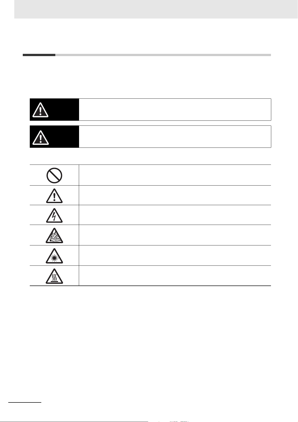
WARNING
CAUTION
Safety Precautions
Symbols and the meanings for safety precautions described in this manual.
In order for the product to be used safely, the following indications are used in this book to draw your
attention to the cautions. The cautions with the indications describe the important contents for
safety.
Indicates a potentially hazardous situation which, if not avoided, will result in minor or moderate
injury, or may result in serious injury or death.
Additionally there may be significant property damage.
Indicates a potentially hazardous situation which, if not avoided, may result in minor or moderate
injury or in property damage.
Meanings of Alert Symbols
General Prohibition
Indicates general prohibitions, including warnings, for which there is no specific symbol.
General Caution
Indicates general cautions, including warnings, for which there is no specific symbol.
Electrical Hazard
Indicates the possible danger of electric shock under specific conditions.
Explosion Hazard
Indicates the possible danger of explosion under specific conditions.
Laser Radiation Hazard
Indicates the possible danger of laser radiation or light.
High Temperature Caution
Indicates the possible danger of injury by high temperature under specific conditions.
24
Vision System FH/FHV/FZ5 Series User’s Manual (Z365)
Page 27
Safety Precautions
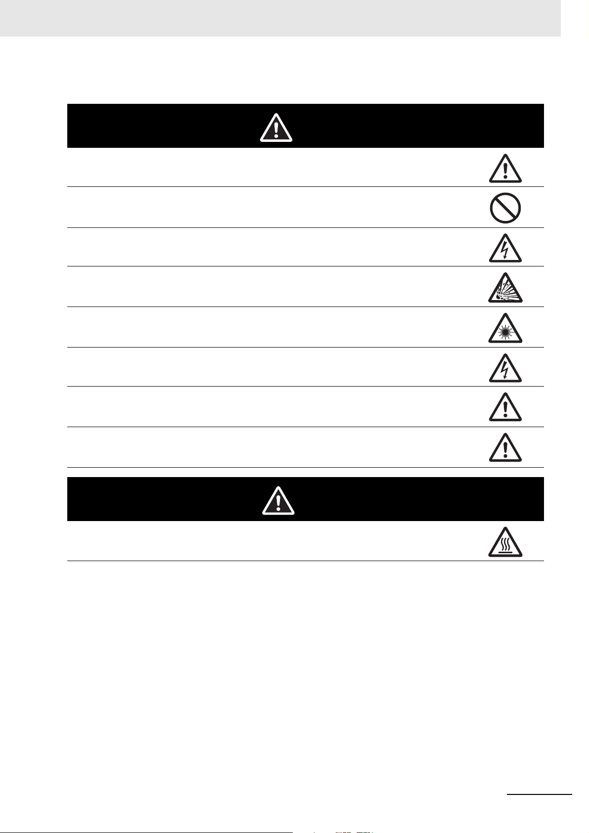
CAUTION
Alert statements in this Manual
WARNING
This product must be used according to this manual or Instruction sheet.
Failure to observe this may result in impairment of functions and performance of the product.
This product is not designed or rated for ensuring safety of persons. Do not use it for such purposes.
Never connect the AC power supply with this product.
When the AC power supply is connected, it causes the electric shock and a fire.
A lithium battery is built into the Controller and may occasionally combust, explode, or burn if not
treated properly. Dispose of the Controller as industrial waste, and never disassemble, apply pressure that would deform, heat to 100°C or higher, or incinerate the Controller.
Since camera that can be connected with this product emits a visible light that may have an adverse
effect on the eyes, do not stare directly into the light emitted from the LED. If a specular object is
used, take care not to allow reflected light enter your eyes.
Do not touch the terminals while the power supply is ON. Doing so may result in electrical shock.
Please take external safety measures so that the system as a whole should be on the safe side even
if a failure of a Sensor Controller or an error due to an external factor occurred. An abnormal operation may result in serious accident.
Please take fail-safe measures on your side in preparation for an abnormal signal due to signal conductor disconnection and/or momentary power interruption. An abnormal operation may result in a
serious accident.
Danger of burns. Do not touch the case while the LED is ON or just after power is turned OFF, since it
remains extremely hot.
Vision System FH/FHV/FZ5 Series User’s Manual (Z365)
25
Page 28

Precautions for Safe Use
Precautions for Safe Use
Condition of the fitness of OMRON products
• Please do not use this product to directly or indirectly use to detect the human body for the purpose
of ensuring the safety. In the same application, please use the safety sensor that is published on our
sensor catalog.
• Omron products are designed and manufactured as general-purpose products for use in general
industrial applications. They are not intended to be used in the following critical applications. If you
are using Omron products in the following applications, Omron shall not provide any warranty for
such Omron products, unless otherwise specifically agreed or unless the specific applications are
intended by Omron.
(a) Applications with stringent safety requirements, including but not limited to nuclear power control
equipment, combustion equipment, aerospace equipment, railway equipment, elevator/lift equipment, amusement park equipment, medical equipment, safety devices and other applications that
could cause danger/harm to people’s body and life.
(b) Applications that require high reliability, including but not limited to supply systems for gas, water
and electricity, etc., 24 hour continuous operating systems, financial settlement systems and other
applications that handle rights and property.
(c) Applications under severe condition or in severe environment, including but not limited to outdoor
equipment, equipment exposed to chemical contamination, equipment exposed to electromagnetic
interference and equipment exposed to vibration and shocks
(d) Applications under conditions and environment not described in specifications
*1. In addition to the applications listed from (a) to (d) above, Omron products (see definition) are not intended for
use in vehicles designed human transport (including two wheel vehicles). Please do NOT use Omron products for vehicles designed human transport. Please contact the Omron sales staff for information on our automotive line of products.
*2. The above is part of the Terms and Conditions Agreement. Please use carefully read the contents of the guar-
antee and disclaimers described in our latest version of the catalog, data sheets and manuals.
Installation Environment (FH/FZ5 series)
• Do not use the product in areas where flammable or explosive gases are present.
• Install the product so that air can flow freely through its cooling vents.
• Clean the ventilation holes and fan outlet regularly to prevent dust and particles from clogging them.
If they are blocked, heat is trapped inside, causing a malfunction.
• Do not install the product close to high-voltage devices and power devices in order to secure the
safety of operation and maintenance.
• Make sure to tighten all installation screws securely.
• When mounting the Sensor Controller using the DIN rail mounting bracket, make sure the screw is
tightened.
• Make sure to mount the product on DIN-rail securely.
26
Vision System FH/FHV/FZ5 Series User’s Manual (Z365)
Page 29

Precautions for Safe Use
Installation Environment (FHV series)
• Do not use the product in areas where flammable or explosive gases are present.
• Do not install the product close to high-voltage devices and power devices in order to secure the
safety of operation and maintenance.
• Do not install the product to a place where vibrations and/or impacts are expected.
• Do not install the product near to a device causing noises. if the product is installed in a noisy environment and operational errors are caused, be sure to take shielding measures.
Power Supply and Wiring (FH/FZ5 series)
• Make sure to use the product with the power supply voltage specified by this manual or Instruction
sheet.
• Do not connect AC power source to Sensor Controller. If connects AC power source, it might be a
cause of the failure.
• Use the wire of a suitable size (AWG 16 to 12) according to the current consumption.
• Use a DC power supply with safety measures against high-voltage spikes (safety extra low-voltage
circuits on the secondary side).
• Keep the power supply wires as short as possible.
• Do the following confirmations again before turning on the power supply.
• Is the voltage and polarity of the power supply correct? (24 VDC)
• Is not the load of the output signal short-circuited?
• Is the load current of the output signal appropriate?
• Is not the mistake found in wiring?
• Is the voltage and polarity of the encoder power (ENC0_VDD/GND ENC1_VDD/GND) supply? (5
VDC)
• The recommended power supply is the S8VS-24 (manufactured by OMRON) or
S8VK-G-24 (manufactured by OMRON).
Power Supply and Wiring (FHV series)
• Make sure to use the product with the power supply voltage specified. If a DC voltage exceeding the
rating or an AC voltage is applied, the circuit parts may be burnt or exploded.
• Do not connect the power supply with polarity reversed.
• Use a DC power supply with safety measures against high-voltage spikes (safety extra low-voltage
circuits on the secondary side).
• Use an independent power source for this product. Do not use a shared power source.
• Never apply more than the rated voltage or AC power supply to this product. It may cause malfunction.
• The recommended power supplies are as follows:
• When attaching the lighting module, use S8VK-G06024 (OMRON) or S8VS-06024 (OMRON).
• When not attaching the lighting module, use S8VK-G06024 (OMRON) or S8VS-06024 (OMRON).
• Wire high-voltage cables or power cables separately from the cables of this product. If the same
cable or duct is used, the product may receive induction and it may cause malfunctioning or breakage.
• Do not short-circuit load on the open collector output.
• Apply load not exceeding the rating.
• When wiring, put a crimp terminal of the specified size. Do not connect wires simply twisted together
to the power supply or terminal block directly.
Vision System FH/FHV/FZ5 Series User’s Manual (Z365)
27
Page 30

Precautions for Safe Use
• If using an I/O cable 20 m long, confirm that the power supply output is 24 VDC or higher. If it is lower
than 24 VDC, the product does not operate.
• Cut off unnecessary signal wires so that they do not contact any other signal wires.
• After wiring the cables, confirm if the power supply is appropriate, if there is miswiring such as shortcircuit of load, if the load current is appropriate, and if FG is connected appropriately. Otherwise, the
product may be broken due to miswiring etc.
• Take enough safety measures such as a failsafe circuit before using the product.
• Be sure to apply Class D grounding (100Ω or lower grounding resistance) to the case of the smart
camera and the ground wire of the I/O cable.
• Do not share the ground wire with some other devices or connect it to the beam of the building. The
product may be adversely affected.
• Determine the contact point as near as possible to shorten the ground wire as much as possible.
The product may be adversely affected.
Ground
• Make sure the power supply circuit of the FH Sensor Controller is insulated from the internal circuit.
Refer to this manual or Instruction sheet.
• When the connected camera to Sensor Control comes packaged with a base, make sure to mount
with the base. Since the enclosure of the camera main body made of metals is short-circuited with
the internal circuit, the internal circuit might be short-circuited with FG if no base is used, so that failures or malfunctions may be caused.
Perform Class D grounding (with a grounding resistance of 100 Ω or less).
Keep the ground line as short as possible by setting the grounding point as close as possible.
Ground the FH Sensor Controller independently. If sharing the ground line with other devices or con-
necting it with a building beam, the Sensor Controller might be adversely effected.
• Check wiring again before turning on the FH Sensor Controller.
• Do not ground the plus (+) terminal when the FH series Sensor Controller is connected to the
FH-SC12/FH-SM12. Doing so may cause a short circuit of the internal circuit, resulting in a malfunction.
The internal circuit is possible to be given damage, it can be cause the failure.
• FH-1000 series
• FH-2000 series
• FH-3000 series
• FH-5000 series
•FH-L series
• Do not ground the plus (+) terminal of the 24 VDC power source when the FH series Sensor Controller is connected to the FH-MT12 with a USB cable. Doing so may cause a short circuit of the internal
circuit, resulting in a malfunction.
• FH-1000 series
• FH-2000 series
• FH-3000 series
• FH-5000 series
•FH-L series
28
Vision System FH/FHV/FZ5 Series User’s Manual (Z365)
Page 31

Precautions for Safe Use
Mounting (FHV series)
• When doing the following, be sure to turn OFF the power of the smart camera main unit or connected
peripheral devices. Not doing so leads to a product failure.
• Cable connection and wiring
• Connector mounting/removal
• Lighting module mounting/removal
• Lens module mounting/removal
• Tighten the mounting screws securely using the defined torque and order described in the Setup
Manual.
• Mount the lens module in the correct direction. Mounting it in the wrong direction may cause malfunction of the device or injury.
• After removing the cable, be sure to put the connector cap. If the connector cap is not put, the product may malfunction or be broken due to entering of foreign materials.
• For the component with a lock mechanism, be sure to confirm that it is locked before using the product.
• Do not apply torsional stress to the cable. Doing so may cause cable breakage.
• Secure the minimum bending radius of the cable. If it cannot be secured, the cable may be broken.
• Assemble as avoiding the water-proof packings and harnesses from being caught by the case, etc.
• Do not use any damaged water-proof packings and light shielding sheet or assemble the product with
foreign materials attached to or caught in.
• Mount the lens module and lighting model in the correct direction. Mounting them in the wrong direction may cause broken or malfunction of the device, or injury.
• Do not touch the lens or image sensor with bare hands. Doing so may lead to malfunctioning or breakage.
Assemble the lens and image sensor with a correct combination. if not, malfunction may result.
Other (FH/FZ5 series)
• Use only the camera and cables designed specifically for the product. Use of other products may
result in malfunction or damage of the product.
• Always turn OFF the power of the Sensor Controller and peripheral devices before connecting or disconnecting a camera or cable. Connecting the cable with power supplied may result in damage of the
camera or peripheral devices.
• For the cable that is flexed repeatedly, use the robotic cable type (Bend resistant camera cable) to
prevent damages.
• Do not apply torsion stress to the cable. It may damage the cable.
• Secure the minimum bending radius of the cable. Otherwise the cable may be damaged.
• Do not attempt to dismantle, repair, or modify the product.
• Should you notice any abnormalities, immediately stop use, turn OFF the power supply, and contact
your OMRON representative.
• While the power is ON or immediately after the power is turned OFF, the Sensor Controller and camera case are still hot. Do not touch the case.
• When disposing of the product, treat it as an industrial waste.
• Do not drop the product nor apply excessive vibration or shock to the product. Doing so may cause
malfunction or burning.
• This product is heavy. Be careful not to drop it while handling.
• A lithium battery is incorporated, so a severe injury may rarely occur due to ignition or explosion.
• Be sure to take fail-safe measures externally when controlling stages and robots by using the measurement results of the Sensor Controller (axis movement output by calibration and alignment measurement).
Vision System FH/FHV/FZ5 Series User’s Manual (Z365)
29
Page 32

Precautions for Safe Use
Other (FHV series)
• Use only the dedicated cable (FHV-VN/FHV-VD), camera-mount lighting controller
(FL-TCC/FLV-TCC), lighting module (FHV-LTM-), and lens module (FHV-LEM-). Otherwise,
the product may malfunction or be broken.
• If anything abnormal occurs, for example, strange smell/sound is detected, the main unit gets very
hot, or a smoke comes, stop using the product, turn OFF the product, and consult OMRON’s branch
or sales office.
• Do not disassemble, deform by pressurizing, incinerate, repair, or alter this product.
• When disposing of the product, treat as industrial waste.
• Do not drop the product or expose it to abnormal vibration or impact. Doing so may lead to product
failure.
• If using the measurement result of the smart camera to operate the stage or robot (output of axis
moving distance by calibration and alignment measurement), be sure to take failsafe measures
externally.
• The water-proof packing and light shielding sheet are rubber products. Avoid storing them in a location where rubber deteriorates.
30
Vision System FH/FHV/FZ5 Series User’s Manual (Z365)
Page 33

Precautions for Correct Use
Installation and Storage Sites for FH-1000/2000/3000/5000
series/FZ5-800/1100/1200 series/FZ5-600 series/FZ5-L series
Install and store the product in a location that meets the following conditions:
• Surrounding temperature of 0 to +50°C *
• No rapid changes in temperature (place where dew does not form)
• Relative humidity of between 35 to 85%
• No presence of corrosive or flammable gases
• Place free of dust, salts and iron particles
• Place free of vibration and shock
• Place out of direct sunlight
• Place where it will not come into contact with water, oils or chemicals
*1. 0 to +45°C for FH-5000 series
1
Precautions for Correct Use
Installation and Storage Sites for FH-L series
Install and store the product in a location that meets the following conditions:
• Surrounding temperature of 0 to +55°C (-25 to +70°C in storage)
• No rapid changes in temperature (place where dew does not form)
• Relative humidity of between 10 to 90%
• No presence of corrosive or flammable gases
• Place free of dust, salts and iron particles
• Place free of vibration and shock
• Place out of direct sunlight
• Place where it will not come into contact with water, oils or chemicals
• Place not affected by strong electro-magnetic waves
• Place not near to high-voltage, or high-power equipment
Installation and Storage Sites for FHV series
In order to prevent the product from becoming inoperable or malfunction, and to prevent other adverse
effects to the performance or equipment, please observe the following.
• A location where the ambient temperature does not exceed the rated range (operating: 0 to 40°C,
storage: -25 to 65°C).
• A location where the temperature does not vary sharply (condensation occurs).
• A location where relative temperature does not exceed a range of 35-85%RH.
• A location not exposed to corrosive gases or combustible gases.
• A location not exposed to dust, salt, or metal powder.
• A location not exposed to direct vibration or impact.
• A location not exposed to strong disturbance light (laser light, arc welding light, or ultraviolet light).
• A location not near a heating appliance or exposed to direct sunlight.
• A location not exposed to mist of water, oil, or chemicals or misty atmosphere.
• A location not exposed to strong magnetic/electric fields.
• A location not near a high-voltage device or power device
• A location where rubber quality is not deteriorated.
Vision System FH/FHV/FZ5 Series User’s Manual (Z365)
31
Page 34

Precautions for Correct Use
Orientation of Product
• For good heat dissipation, install the product only in the position written this manual or Instruction
sheet so as not to block the ventilation holes.
Ambient Temperature
• For good heat dissipation, keep the distance written this manual or Instruction sheet.
• Do not install the product immediately above significant heat sources, such as heaters, transformers,
or large-capacity resistors.
• Do not let the ambient temperature exceed an operating temperature range.
• Provide a forced-air fan cooling or air conditioning if the ambient temperature is near the upper range
of operating temperature range so that the ambient temperature never exceeds the upper range of
operating temperature range.
Noise Resistance
• Do not install the product in a cabinet containing high-voltage equipment.
• Do not install the Sensor Controller within 200 mm of power cables.
Component Installation and Handling (FH/FZ5 series)
• Touching Signal Lines
To prevent damage from static electricity, use a wrist strap or another device for preventing electrostatic discharges when touching terminals or signal lines in connectors.
• Handling a USB Memory/SD memory card.
Refer to Using an External Storage Device in the Vision System FH/FHV/FZ5 series User’s Manual
(Cat. No. W365).
• Do not insert an SD memory card in the reverse orientation, at an angle, or in a twisting manner.
Before removing a USB memory device or SD memory card, make sure that data is not being read or
written to them.
For a USB memory device, the memory device's LED flashes while data is being read or written.
Make sure that the LED stops flashing before removing the memory device.
For an SD memory card, the SD BUSY LED of Sensor Controller flashes while data is being read or
written. Make sure that the LED stops flashing before removing the card.
• Turning OFF the Power
When a message is displayed indicating that a task is in progress, do not turn OFF the power. Doing
so causes the data in the memory to be corrupted, resulting in the product not operating properly
upon the next start-up.
When turns OFF, conform the followings proceedings have completed. and then operate again.
• When saves using Sensor Controller:
Confirm the save processing is completed and next operation is possible.
• When saves using communication command:
Intended command is completed. BUSY signal is turned OFF
• Setting of Power Source
The power source need to be supplied from DC power source apparatus which is taken a save
ultra-low voltage circuit: to protect high voltage.
32
Vision System FH/FHV/FZ5 Series User’s Manual (Z365)
Page 35

Precautions for Correct Use
Component Installation and Handling (FHV series)
• If using a commercially available switching regulator, earth the frame ground terminal.
• If the power supply line has surge, connect a surge absorber according to the operational environment to use the product.
• After wiring the cables, confirm if the power supply is appropriate, if there is miswiring such as shortcircuit of load, or if the load current is appropriate. Otherwise, the product may be broken due to miswiring etc.
• Do not put load on the cables and connectors before wiring them.
• Do not turn OFF the power supply while data are being saved in the smart camera. Otherwise, data
on the memory is broken, so the product does not operate normally when started up next time.
• When turning OFF the power, confirm that data have been saved completely before starting operations.
• When data are saved by operating the sensor controller, the saving process must have been completed and the following user operations must be possible.
• When data are saved using communication commands, processing of the applicable commands
must have been completed and the busy state is OFF.
• If contacting a terminal or a signal cable inside the connector, use a wrist strap to take antistatic measures to prevent breakage due to static electricity.
• If removing the micro SD card, confirm that data are not being read or written before removing it.
• Do not insert the micro SD card inversely, obliquely, or as twisting it.
• While data are being read in or written to the micro SD card, the SD ACCESS LED on the Smart
Camera main unit is turned on for a while. Remove the card after confirming that the LED is completely turned off.
• Except when inserting or removing the micro SD card, put the cover of the micro SD card inserting
connector and screw it up before using the product.
• When a message indicating that processing is being executed is displayed on the screen, do not turn
OFF the power. Otherwise, data on the memory is broken, so the product does not operate normally
when started up again.
• Do not use the product in environments subject to water droplets when an external lighting is connected. The main unit may be broken.
• The RS-232C communication standard defines the maximum cable length as 15 m. Implement this
communication using an I/O cable 2/3/5/10 m long.
• When connecting cables, align terminals and connect them straightly. If not, the terminals bent and
may cause malfunction or unable to communicate normally.
Maintenance
• Turn OFF the power and ensure the safety before maintenance.
• Clean the lens with a lens-cleaning cloth or air brush.
• Lightly wipe off dirt with a soft cloth.
• Dirt on the image element must be removed using an air brush.
• Do not use thinners or benzene.
• To ensure safe access for operation and maintenance, separate the Sensor Controller as much as
possible from high-voltage equipment and power machinery.
Maintenance (FHV series)
• Be sure to put the cap/cover onto the connector not used. Otherwise, the product may malfunction or
get out of order due to entering of foreign materials.
Vision System FH/FHV/FZ5 Series User’s Manual (Z365)
33
Page 36

Precautions for Correct Use
Communication with High-order Device
• After confirming that this product is started up, communicate with the high-order device. When this
product has started up, an indefinite signal may be output from the high-order interface. To avoid this
problem, clear the receiving buffer of your device at initial operations.
Fail-Safe Measures
• When controlling stages and robots using the measurement results from the Sensor Controller (axis
movement output based on calibration and alignment measurement), always take fail-safe measures
within the stage and robot systems, such as checking whether the data obtained from the measurement results is within the range of movement of the stages and robots.
• On a FH Sensor Controller side, supplementary use operations and branches of the Sensor Controller to configure a check flow such as “data should not be externally provide if the data is in a range
from -XXXXX to XXXXX” based on the stage/robots range of movement.
Connecting the Sensor Controller and Monitor with a Switcher and
Splitter (FH/FZ5 series)
• Do not use devices that make the Sensor Controller recognize the monitor again when switching
operation is performed. Re-recognition process in switching operation has an effect such as a delay
in measurement time.
Beam (FHV series)
• The beam center may vary product by product. When mounting this module, be sure to confirm the
center position of the video on the monitor.
The beam center of this product may vary over a couple of pixels due to the variation of ambient temperature because of the material characteristics.
• Select the model by confirming the field of view and camera installation distance on the optical diagram. In addition, the field of view may vary product by product.
When mounting this product, be sure to confirm video using the monitor.
Image Sensor (FHV series)
• For this product, a line may appear depending on the measurement condition or sensitivity because
of the specification of the image sensor.
However, this is not a fault or failure of the product. In addition, although there may be multiple defective pixels, this is not a fault or failure of the product. Use the product as confirming the actual image.
34
Communications with Upper Equipment (FHV series)
• Implement communications with upper equipment after confirming that this product has been started
up. In addition, when this product is being started up, unstable signals may be issued by the upper
interface. In the initial operation, take action such as clearing the receiving buffer of the equipment
used.
Vision System FH/FHV/FZ5 Series User’s Manual (Z365)
Page 37

Precautions for Correct Use
Failsafe Measures (FHV series)
• When operating a stage or robot using measurement results of the Smart Camera (axis moving distance output by the calibration or alignment measurement), take measures as follows: Be sure to
operate the stage or robot after confirming the measurement result data on the stage or robot side
that the data are within the movable range of the stage or robot.
Warm-up (FHV series)
• Turn ON the power and wait for 60 minutes or more before conducting precise inspection. The circuit
is not stable directly after the power is turned ON, so brightness may vary gradually.
Camera Installation (FHV series)
• In an environment exposed to high humidity and sharp temperature fluctuation, the inside of the lighting cover may become cloudy in rare cases. If it becomes cloudy, remove the lighting cover and wipe
off the inside with a soft cloth.
• If installing smart camera main units side by side, secure a space of 30 mm or more wide between
them.
Others (FHV series)
• For better heat radiation, use the separately sold fitting (FHV-XMT-7) or mount the product to the
metal frame (recommended size: 100×110 mm or more and thickness: 10 mm or more).
• Do not assemble the lighting module or water-proof hood in a hot and humid environment. Otherwise,
condensation may occur. If it becomes cloudy, remove the lighting cover and wipe off the moisture
with an absorbent, but soft cloth so as not to damage the product.
• There are two types of polarizing filters: FHV-XPL (for visible light) and FHV-XPL-IR (for both visible
and infrared lights). Use the appropriate option according to the illumination light source.
• If switching the focus for a long period of time continuously except when installing and adjusting the
product, performance may be degraded due to heat generation or abrasion of inner parts.
• When the lens module is mounted to the product, the specifications of vibration tolerance are
changed.
• Do not touch the lens module after it is mounted. Otherwise, it may be broken.
• If using this product without attaching the lighting module in an environment needing water-proof, use
water-proof hood FHV-XHD series.
• Operate the product by using Calculation and Branch processing items on the Smart Camera side
additionally and creating a check flow, for example, if the stage or robot is within a range of -xxxxx to
xxxxx from its movable range, data are not output to outside.
• The lighting module and lens module are fixed to the smart camera with dropout preventing screws.
Do not remove them from the product.
Vision System FH/FHV/FZ5 Series User’s Manual (Z365)
35
Page 38

Precautions for Correct Use
ABC
LED Safety (FHV series)
This product is classified into the following risk groups by IEC62471.
Model Color LED safety Display
FHV-LTM-W White Risk group 2 A
FHV-LTM-R Red Risk group 1 B
FHV-LTM-IR Infrared light Risk group 1 C
Red Risk group 1 B
FHV-LTM-MC
Green Risk group 2 A
Blue Risk group 2 A
Infrared light Risk group 1 C
36
Vision System FH/FHV/FZ5 Series User’s Manual (Z365)
Page 39

Regulations and Standards
All Series
Using Product Outside Japan
This regulation applies to FH/FHV/FZ5 sensor controller and peripheral devices.
If you export (or provide a non-resident with) this product or a part of this product that falls under the
category of goods (or technologies) specified by the Foreign Exchange and Foreign Trade Control Law
as those which require permission or approval for export, you must obtain permission or approval or
service transaction permission) pursuant to the law.
U.S. California Notice:
Regulations and Standards
This product contains a lithium battery for which the following notice applies: Perchlorate Material - special handling may apply.
See www.dtsc.ca.gov/hazardouswaste/perchlorate
Conformance to KC Standards
This regulation applies to FH/FHV/FZ5 sensor controller and peripheral devices.
Observe the following precaution if you use this product in Korea.
• Class A Device (Broadcasting Communications Device for Office Use)
This device obtained EMC registration for office use (Class A), and it is intended to be used in places
other than homes. Sellers and/or users need to take note of this.
FH-1000/2000/3000/5000 series
Conformance to EC/EU Directives
This Sensor Controller is compliant with the standards below:
• EC Directive 2004/108/EC (Until April 19 2016) / EU Directive 2014/30/EU (After April 20 2016)
EN61326-1
Electromagnetic environment: Industrial electromagnetic environment (EN/IEC 61326-1 Table 2)
• Also, the following condition is applied to the immunity test of this product.
• If the level of disturbance of the video is such that characters on the monitor are readable, the test
is a pass.
• This product complies with EC/EU Directives. EMC-related performance of the OMRON devices that
comply with EC/EU Directives will vary depending on the configuration, wiring, and other conditions
of the equipment or control panel on which the OMRON devices are installed.
Vision System FH/FHV/FZ5 Series User’s Manual (Z365)
37
Page 40

Regulations and Standards
• The customer must, therefore, perform the final check to confirm that devices and the overall
machine conform to EMC standards.
• If there is a need to respond to the EC / EU directive, please use by an analog RGB output.
Conformance to UL Standards
This regulation applies to FH-1000 and FH-3000 series Sensor Controller and peripheral devices.
This product complies with UL Standards.
• UL508
This regulation applies to FH-2000 and FH-5000 series Sensor Controller and peripheral devices.
This product complies with UL Standards.
• UL61010-2-201
FH-L series
Conformance to EC/EU Directives
This Sensor Controller is compliant with the standards below:
• EC Directive 2004/108/EC (Until April 19 2016) / EU Directive 2014/30/EU (After April 20 2016)
EN61326-1
Electromagnetic environment: Industrial electromagnetic environment (EN/IEC 61326-1 Table 2)
• Also, the following condition is applied to the immunity test of this product.
• If the level of disturbance of the video is such that characters on the monitor are readable, the test
is a pass.
• This product complies with EC/EU Directives. EMC-related performance of the OMRON devices that
comply with EC/EU Directives will vary depending on the configuration, wiring, and other conditions
of the equipment or control panel on which the OMRON devices are installed.
• The customer must, therefore, perform the final check to confirm that devices and the overall
machine conform to EMC standards.
• If there is a need to respond to the EC / EU directive, please use by an analog RGB output.
Conformance to UL Standards
This regulation applies to FH-L series Sensor Controller and peripheral devices.
This product complies with CSA Standards.
• UL 61010-2-201
38
Vision System FH/FHV/FZ5 Series User’s Manual (Z365)
Page 41

FHV series
Conformance to EC/EU Directives
The product is compliant with the standards below:
• EU Directive 2014/30/EU (After April 20 2016)/EU EN61326-1 Electromagnetic environment: Industrial electromagnetic environment (EN/IEC 61326-1 Table 2)
• This product complies with EC/EU Directives. EMC-related performance of the OMRON devices that
comply with EC/EU Directives will vary depending on the configuration, wiring, and other conditions
of the equipment or control panel on which the OMRON devices are installed.
• The customer must, therefore, perform the final check to confirm that devices and the overall
machine conform to EMC standards.
FZ5 series/FZ5-L series
Regulations and Standards
Conformance to EC/EU Directives
This Sensor Controller is compliant with the standards below:
• EC Directive 2004/108/EC (Until April 19 2016) / EU Directive 2014/30/EU (After April 20 2016)
EN61326-1
• Electromagnetic environment: Industrial electromagnetic environment (EN/IEC 61326-1 Table 2)
• Also, the following condition is applied to the immunity test of this product.
• If the level of disturbance of the video is such that characters on the monitor are readable, the test
is a pass.
• This product complies with EC/EU Directives. EMC-related performance of the OMRON devices that
comply with EC/EU Directives will vary depending on the configuration, wiring, and other conditions
of the equipment or control panel on which the OMRON devices are installed.
• The customer must, therefore, perform the final check to confirm that devices and the overall
machine conform to EMC standards.
Conformance to CSA Standards
This product complies with CSA Standards.
• CSA C22.2 No.61010-1
Vision System FH/FHV/FZ5 Series User’s Manual (Z365)
39
Page 42

Revision History
Revision History
A manual revision code appears as a suffix to the catalog number on the front and back covers of the
manual.
Cat. No.
Rev. No. Rev. Date Revision Contents Software Version
01 Apr. 2016 Additional descriptions of software updates, FH-L
02 Mar. 2017 Additions for software version upgrade. Ver. 5.71
03 Jun. 2017 Additions for software version upgrade. Ver. 5.72
04 Jul. 2018 Additions for software version upgrade. Ver. 6.10
05 Nov. 2018 Additions for software version upgrade. Ver. 6.20
Z365-E1-05
Revision code
Ver. 5.60
series product information and catalogue number
revisions for Ver. 5.55.
40
Vision System FH/FHV/FZ5 Series User’s Manual (Z365)
Page 43

Overview
This section describes the basic flow and preparations that are necessary to start operation.
1-1 Checking the System Configuration . . . . . . . . . . . . . . . . . . . . . . . . . . . . . . 1-2
1-2 Flow of Application . . . . . . . . . . . . . . . . . . . . . . . . . . . . . . . . . . . . . . . . . . . . 1-7
1
1-1-1 System Configuration . . . . . . . . . . . . . . . . . . . . . . . . . . . . . . . . . . . . . . . . . . . 1-2
1-1-2 Functional Comparison between the FH-series, FHV-series and FZ5-series Con-
trollers . . . . . . . . . . . . . . . . . . . . . . . . . . . . . . . . . . . . . . . . . . . . . . . . . . . . . . . . .1-3
Vision System FH/FHV/FZ5 Series User’s Manual (Z365)
1 - 1
Page 44

1 Overview
Communications protocol
Communications cable Connector on the FH
Parallel Parallel I/O cable I/O connector
Ethernet cable Ethernet connector PLC Link
RS-232C cable RS-232C connector
EtherNet/IP Ethernet cable Ethernet connector
EtherCAT Ethernet cable
Connector for EtherCAT communications
Ethernet cable Ethernet connector Non-procedure
RS-232C cable RS-232C connector
LCD
FZ-M08
(8.4-inch)
Camera
Camera
Sensor Controller
• Controller with 2 Camera channels
• Controller with 4 Camera channels
• Controller with 8 Camera channels
Camera Cable (e.g., FZ-VS3)
Communications cable
External device (e.g., PLC)
*1. FZ-MEM2G or FZ-MEM8G USB Memory is sold separately.
Lighting
Monitor cable
(e.g., FH-VMDA)
Up to 2, 4, or 8 Cameras
depending on the model of
the FH/FZ5-series Sensor
Controller
Example
FH series System
1-1 Checking the System Configuration
1-1-1 System Configuration
The FH/FHV/FZ5 is a Vision Sensor that uses a controller to process measurements of objects that are
imaged with a Camera.
You connect an LCD for operations and monitoring, and various Cameras to the FH/FHV/FZ5-series
Sensor Controller.
You connect external devices, such as a PLC or a computer, through a parallel, Ethernet, or RS-232C
cable.
You can connect up to eight Cameras, depending on the model of the Controller.
To measure more than one line with a single Sensor Controller, you assign the Camera for the measurements to each line beforehand, and switch between Cameras during the measurement flow.
For details of the system configuration each series or basic configuration, refer to the Vision System
FH/FHV/FZ5 series Hardware Setup Manual (Cat. No. Z366)/FHV Series Smart Camera Setup Manual
(Z408).
1 - 2
Vision System FH/FHV/FZ5 Series User’s Manual (Z365)
Page 45

1 Overview
1-1-2 Functional Comparison between the FH-series, FHV-series and
FZ5-series Controllers
The following table shows the differences between the FH series, FHV series and FZ5 series.
The fastest measurement speed is FH-5000 series.The next speed is the following:FH-5000 series >
FH-3000 series > FH-2000 series > FH-1000 series > FZ5-1200 series > FZ5-1100series > FZ5-800
series > FZ5-600 series > FH-L series > FHV series > FZ5-L series.Select the appropriate Sensor Controller series according to the application as below table.
Principal Difference
1-1 Checking the System Con-
figuration
1
1-1-2 Functional Comparison between the FH-series, FHV-series and FZ5-series Controllers
Controller
model
Function
Number of
Camera
connections
Operation
*2
mode
Standard Yes
Double
Speed
Multi
input
Non-stop
adjustent
mode
Multi-line
randomtrigger
mode
Number of
scenes
(number of
line process
changes)
Input
interface
EtherCAT
External
storge
USB
memory
SD
memory
card
microSD
card
Sysmac
Studio
support
FH Series
FH-
050
8
Ye s N o
Ye s N o
Ye s
(Maximum 8 lines)
128
OK ―
OK ― OK
OK ―
― OK ―
OK ―
FH-
050
-20
*1
424 2 ― 424 2
*3
-10
FH-
050
FH-
L
-10
No Yes
FH-
L
FHV
Series
FHV7-
FZ5-
11
-10
(Maximum 2
lines)
FZ5-
11
FZ5 Series
No
FZ5-L35 -10
FZ5-6-10
FZ5-L35
FZ5-6
Vision System FH/FHV/FZ5 Series User’s Manual (Z365)
1 - 3
Page 46

1 Overview
Controller
model
Function
Menu
languages
Monitor
Interface
FH-
050
-20
Japanese, English, Simplified Chinese, Traditional, Chinese,
Korean, German, French, Spanish, Italian, Vietnamese, and Polish
DVI connection
(Recognize the recommended resolu-
FH-
050
-10
FH Series
FH-
050
FH-
L
-10
FH-
L
tion automatically)
RGB connection
(Resolution XGA 1024×768 dot)
*1. Up to four 12-/20.4-megapixel cameras can be connected. Do not connect more than five cameras when using only
12-/20.4-megapixel cameras. When mixing 12-/20.4-megapixel cameras with other cameras, you can connect up to
four 12-/20.4-megapixel cameras and also connect up to four other cameras, so a total of eight cameras can be connected.
FHV
Series
FHV7-
FZ5-
11
-10
FZ5-
11
― LCD Integral
Controller
*5
FZ5 Series
FZ5-L35 -10
FZ5-6-10
FZ5-L35
FZ5-6
Japanese, English,
Simplified Chinese,
*4
-10 :
and Traditional Chinese
FZ5-L35 /FZ5-L35
(Resolution XGA 1024×768
dot)
FZ5-6 /FZ5-6
LCD Integral Controller
-10 :
*5
*2. Select the Operation mode for your application purpose.
For Operation mode, refer to the following: Refer 4-4 Setting Operation Mode [Startup Settings] on page 4-12.
*3. The Conversion Scene Group Data Tool allows you to create a scene group of more than 129 scenes.
*4. Nine languages are selectable in the [Language setting] dialog box under [System Settings], however, only
Japanese, English, Simplified Chinese, and Traditional Chinese can be used. If a language other than these
four languages is selected, the menus will appear in English. The menus will also appear in English if system
data with set languages other than these four languages is loaded.
*5. Output to an external monitor is disabled in the default settings.
If output to an external monitor is needed, contact your OMRON representative.
System Settings
Sensor Controller's Model
Menu
Sub
Menu
Startup Startup
setting
Tab Group Parameter
Language
Language
Setting
Basic Relocate
memories
Communication
Communication
module
select
Operation
mode
Operation
mode
setting
Relocate
memories
Serial
(RS-232C/
422)
FieldBus Yes
Operation
mode
Parallel
Execute
FH series
FH1000/
2000/
3000/
FH-L
series
FZV
series
5000
series
Yes
*2
No
Yes
Yes
*5
Yes No
FZ5 series
FZ5-
800/
1100/
1200
FZ600
series
series
*3
*4
Yes No
FZ5-L
series
*1
Yes
*6
*7
1 - 4
Vision System FH/FHV/FZ5 Series User’s Manual (Z365)
Page 47

1 Overview
Sensor Controller's Model
FH series
FH-
Menu
Sub
Menu
Tab Group Parameter
1000/
2000/
3000/
FH-L
series
FZV
series
5000
series
Camera
Camera
connection
Intercamera
setting
Camera 0
to 7
STEP
camera
Delay 0 to 7
*8
Transmission speed
*8
0 to 7
Output
signal
setting
Common
setting
Line
setting
Output
signal
SHTOUT
delay
*8
SHTOUT
width
SHTOUT
polarity
Communication
Parallel Confirma-
tion
Input state STEP0-7
DSA0-7
DI LINE0-2 No
Yes
*9
*11
*2 *12
No
ACK Yes No
RS232C/422
Setting Interface
No
*13
(Normal)
Ethernet
(Normal
(UDP))
Setting Address
setting
Address
*14
No
*2
setting 2
Input/
Output
setting
Output
IP address
Input
Yes No
port No
Output
port No
Other Fan
control
Low rotation/
High rotation
No
*2
setting
Encoder
trigger
Yes N o
*2
setting
Network
drive
S-Z
Yes
setting
*1. Four languages are supported. If a non-supported language is selected, it will default to English.
*2. Setting is disable.
*3. Touch Panel Monitor (FH-MT12) is disable.
*4. EtherCAT setting is disable.
*5. Multi-line Random-trigger Mode setting is disable. If set Multi-line Random-trigger mode, perform in Standard mode.
FZ5 series
FZ5-
800/
1100/
1200
series
No
*10
*2
Yes N o
FZ600
series
*2
No
*2
Yes
Yes
FZ5-L
series
*2
*2
*2
*15
1-1 Checking the System Con-
figuration
1
1-1-2 Functional Comparison between the FH-series, FHV-series and FZ5-series Controllers
Vision System FH/FHV/FZ5 Series User’s Manual (Z365)
1 - 5
Page 48

1 Overview
*6. Operation mode tab is not displayed.
*7. Parallel processing tub is not displayed.
*8. Depending on the number of camera port of Sensor Controller.
*9. Enable only STEP 0 to 2.
*10.Enable only STEP 0.
*11.Enable only DSA 0 to 2.
*12.Enable only DSA 0.
*13.Disable to set. RS-422 is not supported.
*14.Supported only the Sensor Controller has 2 port: FH--10, FH--20
*15.Enable to set only 1 Sensor Controller under network.
1 - 6
Vision System FH/FHV/FZ5 Series User’s Manual (Z365)
Page 49

1-2 Flow of Application
1 Overview
1-2 Flow of Application
The following table shows the flow for using the FH/FHV/FZ5.
Procedure Description Reference
Preparations Installation and Wiring Vision System FH/FZ5 Series Hardware
Setup Manual (Cat. No. Z366)
FH Instruction Manual
FZ5 Instruction Manual
FHV Series Smart Camera Setup Manual
(Z408)
FHV Instruction Manual
↓
Turning ON Power Vision System FH/FZ5 Series Hardware
Setup Manual (Cat. No. Z366)
FH Instruction Manual
FZ5 Instruction Manual
FHV Series Smart Camera Setup Manual
(Z408)
FHV Instruction Manual
↓
Language Selection in Dialog Box (only when
the Sensor Controller is started for the first time)
↓
Main Window (Layout 0) Display Refer to 8-2 Adjustment Windows and Run
↓
Camera Adjustments (Display the settings dialog box for a Camera Image Input processing
item.)
↓
Select [Tool] − [System settings], and then
under [Startup setting], set the settings for
[Basic], [Communication], and [Operation
mode].
↓
Click the [Data save] button, and then select
[Function] − [System restart].
↓
Select [Tool] − [System settings], and then set
the settings for [Camera], [Communication] and
[Other].
↓
Click the [Data save] button, and then select
[Function] − [System restart].
Refer to 4-1 Selecting Language [Startup Set-
tings] on page 4-2
Windows on page 8-11
Refer to 3-1 Preparing the Controller and
Cameras on page 3-2
Refer to Section 4 Setting the Controller on
page 4-1
Refer to 3-6 Saving Settings before Turning
OFF the Power and Restarting on page 3-34
Refer to Section 4 Setting the Controller on
page 4-1
Refer to 3-6 Saving Settings before Turning
OFF the Power and Restarting on page 3-34
.
.
.
.
.
1
.
.
Vision System FH/FHV/FZ5 Series User’s Manual (Z365)
1 - 7
Page 50

1 Overview
Procedure Description Reference
Scene Editing In the Main Window (layout 0), edit the mea-
Testing Execute test measurements.
Measuring
(Operation)
Management
and Analysis
↓
Refer to Section 5 Creating Measurement
surement flow.
• Register processing items.
• Set the properties for each processing item.
↓
Click the [Data save] button. Refer to 9-2 Saving Settings Data to the
↓
(In the Main Window (layout 0), click the [Measure] button.)
↓
Adjust the parameters for each processing item. Vision System FH/FHV/FZ5 Series Process-
↓
Click the [Data save] button. Refer to 9-2 Saving Settings Data to the
↓
In the Main Window (layout 0), click the [Switch
layout] button, and then select [Main Window
(Layout 1)].
↓
In the Main Window (layout 1), check the communications with the PLC.
↓
In the Main Window (layout 1), execute commands from the PLC, such as measurement
trigger commands.
↓
Save and analyze measurement data and
images.
Scenes on page 5-1
Flash Memory on page 9-7
Refer to 6-1 Executing Test Measurements
on page 6-3
ing Item Function
Reference Manual (Cat. No. Z341)
Flash Memory on page 9-7
Refer to Section 6 Performing Measurement
and Adjustment on page 6-1
Vision System FH/FHV/FZ5 Series User's
Manual for Communications
Settings (Cat. No. Z342)
Vision System FH/FHV/FZ5 Series User's
Manual for Communications
Settings (Cat. No. Z342)
Refer to 6-5 Analyzing Inspection and Mea-
surement Results [NG Analyzer] on page 6-
29.
Refer to Section 9 Saving/Loading Data on
page 9-1
.
.
.
.
.
.
1 - 8
Vision System FH/FHV/FZ5 Series User’s Manual (Z365)
Page 51

Features
A measurement flow consist of a series of combined processing items and is called a
scene. This section explains how to create and edit scenes.
2-1 Basic Mechanism for Measurements . . . . . . . . . . . . . . . . . . . . . . . . . . . . . . 2-2
2-2 Support for a Variety of Scenes and Measurement Lines . . . . . . . . . . . . . 2-4
2
Vision System FH/FHV/FZ5 Series User’s Manual (Z365)
2 - 1
Page 52

2 Features
Additional Information
PLC or other external device
Image Input
Defect
Search
Measurement flow
FH/FZ5
Output Unit
Camera
Measurement
trigger
The measurement flow is executed basically in
order of the unit numbers.
Measurement
results are
output.
Measurement
processing of
the input image
Image input
from the
Camera
• Judgement
result
• Measured
values
2-1 Basic Mechanism for Measurements
An FH/FHV/FZ5-series Sensor Controller uses pre-built packages that contain all the processing tasks
(for image input, measurement processing, displays, outputs, etc.) that are required for vision inspections.
You arrange these packaged processes in order of execution of the vision inspection.
An FH/FHV/FZ5-series Controller executes vision inspections according to user-created flows.
In the FH/FHV/FZ5, a flow that contains packaged processes that are arranged in order of execution of processing items and image processing is called a measurement flow.
Processing items and measurement flows can have more than one setting. You can switch the
setting based on the scene to inspect. (Refer to Section 5 Creating Measurement Scenes)
Concept of Measurement Processing
When the FH/FHV/FZ5 receives a measurement trigger from the PLC or other external device, the
image input from a Camera, measurement processing, and output of measurement results (e.g.,
OK/NG judgement results) are executed in the order that those processing items are registered in
the measurement flow.
• In the measurement flow, you can change the processing to execute based on the inspection results
or input conditions of the vision inspection.
• You can use macro processing to execute pre-packaged processing items and functions in the FH/
FHV/FZ5 to create original programs. This allows you to create original measurement processes, dis-
2 - 2
Vision System FH/FHV/FZ5 Series User’s Manual (Z365)
Page 53

2 Features
play processing, input and output processing, and settings dialog boxes that are custom-tailored to
your application.
2-1 Basic Mechanism for Measurements
2
Vision System FH/FHV/FZ5 Series User’s Manual (Z365)
2 - 3
Page 54

2 Features
Image Input
Defect
Search
Measurement flow
Output Unit
Scene groups (0 to 31)
Scene group 0
Scenes (0 to 127)
Scene 0
2-2 Support for a Variety of Scenes and
Measurement Lines
You can have more than one setting for a measurement flow, depending on the inspections. This is
called a scene and you can set up to 128 scenes. Refer to 5-1 What Is a Scene? on page 5-2.
You can also combine more than one scene into a scene group. Management of scenes by scene
groups increases the number of scenes that you can handle. Refer to 7-1 What Is a Scene Group? on
page 7-2.
2 - 4
Vision System FH/FHV/FZ5 Series User’s Manual (Z365)
Page 55

2 Features
C
If you have more than one measurement line, the FH allows you to selectively execute up to eight measurement lines. This allows you to maintain settings for the scenes and scene groups for every line from
0 to 7.
2-2 Support for a Variety of Scenes and
You can connect up to eight Cameras to the FH, (four for the FZ5), and selectively control each Camera. Refer to Multi-line Random-trigger Mode on page 4-19.
FH
ontroller
Line 0
Camera
Line 1
......
You can connect a
total of eight
Cameras for all
lines combined.
Line 7
Scene groups (0 to 31)
Scenes (0 to 127)
Scene groups (0 to 31)
Scenes (0 to 127)
You can
create
settings for
up to 8 lines.
......
Scene groups (0 to 31)
Measurement Lines
2
Scenes (0 to 127)
Vision System FH/FHV/FZ5 Series User’s Manual (Z365)
2 - 5
Page 56

2 Features
2 - 6
Vision System FH/FHV/FZ5 Series User’s Manual (Z365)
Page 57

Basic Operations
This section describes test methods for checking whether correct measurement can be
performed at the set conditions and describes useful functions for operation.
3-1 Preparing the Controller and Cameras . . . . . . . . . . . . . . . . . . . . . . . . . . . . 3-2
3-1-1 Camera Setup . . . . . . . . . . . . . . . . . . . . . . . . . . . . . . . . . . . . . . . . . . . . . . . . 3-2
3-1-2 Preparing a Controller . . . . . . . . . . . . . . . . . . . . . . . . . . . . . . . . . . . . . . . . . . 3-4
3-1-3 Adjusting the Camera . . . . . . . . . . . . . . . . . . . . . . . . . . . . . . . . . . . . . . . . . . . 3-5
3-2 Basic Knowledge about Operations . . . . . . . . . . . . . . . . . . . . . . . . . . . . . . . 3-6
3-2-1 Inputting Values . . . . . . . . . . . . . . . . . . . . . . . . . . . . . . . . . . . . . . . . . . . . . . . 3-6
3-2-2 Inputting Text . . . . . . . . . . . . . . . . . . . . . . . . . . . . . . . . . . . . . . . . . . . . . . . . . 3-7
3-2-3 Selecting Files and Folders . . . . . . . . . . . . . . . . . . . . . . . . . . . . . . . . . . . . . 3-10
3-2-4 Available Operations in Select File Window . . . . . . . . . . . . . . . . . . . . . . . . . 3-13
3-2-5 Using the Zoom Function . . . . . . . . . . . . . . . . . . . . . . . . . . . . . . . . . . . . . . . 3-14
3-2-6 Setting Figures . . . . . . . . . . . . . . . . . . . . . . . . . . . . . . . . . . . . . . . . . . . . . . . 3-15
3-2-7 Changing the Image Mode and Other Display Contents . . . . . . . . . . . . . . . 3-24
3-2-8 Changing the Display Ratio . . . . . . . . . . . . . . . . . . . . . . . . . . . . . . . . . . . . . 3-25
3-3 Checking System Information . . . . . . . . . . . . . . . . . . . . . . . . . . . . . . . . . . 3-27
3-4 Checking the Memory Consumption and Percentage of Memory Used . 3-31
3
3-5 Capturing Screen Images 3-32
3-6 Saving Settings before Turning OFF the Power and Restarting . . . . . . . 3-34
3-6-1 Saving the Setting to the Controller [Data Save] . . . . . . . . . . . . . . . . . . . . . 3-34
3-6-2 Device Information Storage Tool . . . . . . . . . . . . . . . . . . . . . . . . . . . . . . . . . . 3-35
3-6-3 Restarting the Controller: [System Restart] . . . . . . . . . . . . . . . . . . . . . . . . . 3-37
3-7 Initializing the Controller . . . . . . . . . . . . . . . . . . . . . . . . . . . . . . . . . . . . . . . 3-39
3-8 Turning OFF the LCD . . . . . . . . . . . . . . . . . . . . . . . . . . . . . . . . . . . . . . . . . . 3-41
3-8-1 Turning OFF the LCD [LCD OFF] . . . . . . . . . . . . . . . . . . . . . . . . . . . . . . . . . 3-41
3-8-2 Restoring Power to the LCD . . . . . . . . . . . . . . . . . . . . . . . . . . . . . . . . . . . . . 3-41
Vision System FH/FHV/FZ5 Series User’s Manual (Z365)
3 - 1
Page 58

3 Basic Operations
Important
3-1 Preparing the Controller and Cam-
eras
3-1-1 Camera Setup
FH series/FZ5 series Sensor Controllers use the CameraLink standard for camera connection. At normal camera connection, a single camera cable is used for a single camera, and each camera is connected to the Sensor Controller in the CameraLink base configuration. Starting from camera connector
0 on the Sensor Controller, connect cameras to the camera connectors you want to use in ascending
order of camera connector number.
• Immediately after starting up the FH series/FZ5 series Sensor Controller and immediately
after changing scenes, there will be no input image. No input image is processed as the same
color image as in the factory default state.
• If you open the Properties Dialog Box before inputting an image, click the Cancel button to
close the dialog box. Pressing the OK button in the dialog box will change the setting to the
same color camera setting as the factory default setting.
Refer to The measurement NG (image mismatch) error will result when connecting a mono-
chrome camera on page 11-11.
3 - 2
Vision System FH/FHV/FZ5 Series User’s Manual (Z365)
Page 59

3 Basic Operations
Using Two Cables for High-frame-rate Camera Use (FH series only)
3-1 Preparing the Controller and Cameras
FH series Sensor Controllers support the CameraLink standard’s Base Configuration and Medium Configuration.
The Medium Configuration enables use at a higher frame rate than the Base Configuration, reducing
image input time. The configuration that can be connected will depend on the connected cameras.
See the instruction sheet of the cameras you are using.
To connect a camera in the Medium Configuration, you will need to use two camera cables of the same
type and length to connect the camera and Sensor Controller (two-cable connection).
Sensor Controller camera connectors should be connected as a pair with ascending consecutive even
and odd numbered connectors.
The table below shows the camera connector and camera number assignments when connecting the
Sensor Controller and camera cable with a two-cable connection.
Camera numbers for operation modes other than multi-line random trigger
mode
The table below shows the camera connector and camera number assignments when the operation
mode is a mode other than the multi-line random trigger mode.
A number corresponding to a Sensor Controller camera connector number is assigned for the camera number. When using two-cable connection, the even number in the pair of ascending consecutive camera connector numbers is assigned as the camera number.
Sensor Controller
camera connector
number
0000
11 1
2222
33
4 4 4 Not connected
55 5
6666
77
Example when all cam-
eras use one-cable con-
nection
Camera number in application software
Example when all cam-
eras use two-cable con-
nection
Example when combining
one- and two-cable con-
nection
3
3-1-1 Camera Setup
Camera numbers for multiple-line random trigger mode
The table below shows the camera connector and camera number assignments when the operation
mode is the multi-line random trigger mode. This table is an example showing the camera number
assignments when the number of lines is two.
Camera numbers are assigned for each line in ascending order starting from 0. For two-cable connection, camera numbers are assigned in ascending order regardless of camera connector number
Vision System FH/FHV/FZ5 Series User’s Manual (Z365)
pairs.
Sensor Con-
troller cam-
era
connector
number
00 ---0
11 --- 1
22 ---2
33 --4 --- 0
5 --- 1 --- 0
Example when all cameras
use one-cable connection
Line 0 Line 1 Line 0 Line 1 Line 0 Line 1
Camera number in application software
Example when all cameras
use two-cable connection
---
---
---
0 --- Not connected
Example when combining
one- and two-cable connec-
0
2
tion
---
---
3 - 3
Page 60

3 Basic Operations
Important
Additional Information
Sensor Con-
troller cam-
era
connector
number
6 --- 2
7 --- 3
Example when all cameras
use one-cable connection
Line 0 Line 1 Line 0 Line 1 Line 0 Line 1
Camera number in application software
Example when all cameras
use two-cable connection
---
2
Example when combining
one- and two-cable connec-
tion
---
• When connecting cameras with two-cable connection, use a pair of ascending consecutive
even and odd numbered Sensor Controller camera connector numbers for each camera. You
will not be able to get the image acquisitions correctly if you use camera connectors with
non-consecutive connector numbers, or if an odd numbered connector has a lower number
than the even numbered connector it is paired with.
• CameraLink medium configuration is only supported by FH series Sensor Controller.
• When [Operation mode setting] has been set to the multi-line random trigger mode, changing
the camera connections or [Multi-line Random-trigger mode] in the system settings may
change camera number assignments in line with the change made. After changing the camera connections or [Multi-line Random-trigger mode], before using the Sensor Controller,
check the camera numbers in the property setting screen for the [Camera Image Input] processing items or [Camera Image Input FH] processing items.
• STGOUT signals (STGOUT0 to STGOUT7) signals are tied to the camera connector numbers, not the camera numbers. When using CameraLink Medium Configuration or Multi-line
Random-trigger mode, check the camera connector number of a Sensor Controller that corresponds to the camera number.
• SHTOUT signal (SHTOUT0 to SHTOUT7) are tied to the Line number, not camera number.
When use Multi-line random-trigger mode, confirm the Line number and use SHTOUT signal.
1
When connecting cameras with two-cable connection, the camera connection screen in the
system settings displays the camera model for one member of the pair of camera connector
numbers, and displays [Disconnect] for the other.
One-cable Camera Connection
FH series/FZ5 series Sensor Controllers support the CameraLink standard’s Base Configuration. In the
base configuration, one camera cable is used to connect one camera. Starting from camera connector
0 on the Sensor Controller, connect cameras to the camera connectors you want to use in ascending
order of camera connector number.
3-1-2 Preparing a Controller
No special preparations are required with this Controller because processing items are pre-installed.
Please check that the Controller is turned On and that the Main Window is displayed.
For details, refer to the Vision System FH/FZ5 series Hardware Setup Manual (Cat. No. Z366)/FHV
Series Smart Camera Setup Manual (Z408).
The first time the program is started, the Language Setting Dialog Box is displayed. Select the language.
Refer to 4-1 Selecting Language [Startup Settings] on page 4-2.
3 - 4
Vision System FH/FHV/FZ5 Series User’s Manual (Z365)
Page 61

3 Basic Operations
Additional Information
Important
Adjusting the Position of
the Measurement Target
Model
Serial number
Check the model and serial number.
3-1-3 Adjusting the Camera
Check the images that are being taken.
Adjust the position of measurement objects and the focus of the lens.
1 Click the upper left corner of the Image Pane, and then select [Image mode] − [] − [Through].
The through image from the Camera is displayed in the Image Pane.
Refer to 3-2-7 Changing the Image Mode and Other Display Contents on page 3-24.
2 Adjust the position of measurement objects so that they display at the center of the monitor.
3 Adjust the focal distance of the lens.
3-1 Preparing the Controller and Cameras
3
3-1-3 Adjusting the Camera
If a Camera is used together with a lens, turn the focus ring on the lens to adjust the focus.
Refer to Lens Adjustment Setting in the Vision System FH/FHV/FZ5 Series Processing Item
Function Reference Manual (Cat. No. Z341).
When using a Compact Digital Camera, check that the model and serial number of the Camera
Head and Camera Amplifier match. When a Camera Head and Camera Amplifier with different
models and serial numbers are connected, they may not operate correctly.
Vision System FH/FHV/FZ5 Series User’s Manual (Z365)
3 - 5
Page 62

3 Basic Operations
3-2 Basic Knowledge about Operations
3-2-1 Inputting Values
This section describes how to input values required for setting the judgement conditions and communication specifications. Methods for setting up values include the following, depending on the settings.
• Specify values directly with the numeric keyboard
Used to enter specific values, or to fine-tune the value with the UP and DOWN keys.
• Set numerical values by dragging the slider
Setting values can be done by dragging the slider on the screen.
The method for displaying the numeric keyboard and setting values is explained here. For other methods, refer to individual setting descriptions.
1 Click [...] in the item in which a value is to be set.
The numeric keyboard is displayed.
2 Click the numeric keys to input values.
The numerical value is input.
To fine-tune the value, click the UP or DOWN key to increase or decrease the value.
3 Click [OK].
This verifies the value and closes the numeric keyboard.
3 - 6
Vision System FH/FHV/FZ5 Series User’s Manual (Z365)
Page 63

3 Basic Operations
3-2-2 Inputting Text
This section describes methods for inputting file names and descriptive text.
Screen keyboard
The following software keyboard is displayed in the window for inputting text depending on the sensor
controller.
Switching operation will differ depending on the screen keyboard.
FH Series Sensor Controller
Tilde key
3-2 Basic Knowledge about Operations
3
3-2-2 Inputting Text
Application key
Switch between Japanese (hiragana) input/Japanese (katakana) input/Alphabet-Japanese converted
input using the following procedure.
• Use the following procedure to switch between keyboard display languages.
The screen keyboard is by default English, with English characters shown on the keys.
1 To change characters displayed on the keys, press [Shift] + [Left Alt].
To use the [Shift] + [Left Alt] key combination, first hold down [Shift], and while doing so, press
and press again [Left Alt].
2 Display the keys and carry out text input, and confirm the keyboard has been switched.
This switches the language.
• Use the following procedure to switch between kana input and alphabet-Japanese converted input.
The screen keyboard uses an English keyboard layout, with alphabet-Japanese converted input the
default. Switching the keyboard display language to Japanese switches to kana input.
1 To switch between Japanese (katakana) input/Alphabet-Japanese converted input, click
[Ctrl] + [Shift] + [Caps].
To use the [Ctrl] + [Shift] + [Caps] key combination, first hold down [Ctrl], then hold down [Shift]
and press [Caps].
Then, release [Caps], release [Shift], then release [Ctrl].
2 Display the keys and carry out text input, and confirm the keyboard has been switched.
Vision System FH/FHV/FZ5 Series User’s Manual (Z365)
3 - 7
Page 64

3 Basic Operations
Additional Information
• Use the following procedure to switch kana-kanji conversion ON/OFF.
To input kanji characters, it is necessary to start the IME. There are two ways to do this.
1 To toggle between IME ON/OFF, press [Alt] + [~] (tilde).
To use the [Alt] + [~] key combination, first hold down [Alt], and while doing so, press and press
again [~].
2 Alternatively, turn the IME ON by pressing the [Application] key, and from the menu,
select [Open IME].
To turn the IME OFF, press the [Application] key, and from the menu, select [Close IME].
• If you connect a keyboard to the Sensor Controller with a USB connection, the key arrangement will be the same as an English keyboard.
• In Japanese, the [¥] (yen) character is used to indicate paths between folders, however if the
¥ character is not shown on the keyboard, then substitute the [\] (backslash) key.
FZ5-1100 series Sensor Controller
Keyboard display languages, switching between kana conversion and alphabet-Japanese conversion, and turning kana-kanji conversion ON/OFF is the same as on the FH series screen keyboard.
FZ5-600 series/FZ5-L series Sensor Controller
In the FZ5-600 and FZ5-L series sensor controllers, tabs are displayed for each input character type.
3 - 8
Vision System FH/FHV/FZ5 Series User’s Manual (Z365)
Page 65

3 Basic Operations
Important
Additional Information
Operation Method
1 Click [...] in the item in which a character string is to be set.
The soft keyboard is displayed.
2 Switch the tabs as needed and Click the character that is to be input.
Depending on the used languages settings (Refer to 4-1 Selecting Language [Startup Settings] on
page 4-2 in order to switch display languages, input characters using the following format.
After the language identifier surrounded by single-byte ¥ (yen) or single-byte \ (backslash) symbols, detail the character to input.
Example: if the used language setting is Japanese, then [ ] will be displayed, and if this
is English, then [input character] will be displayed.
-----------------------------------------------
¥jpn¥ ¥eng¥input character
or
\jpn\ \eng\input character
-----------------------------------------------
Language identifiers:
jpn: Japanese
eng: English
3-2 Basic Knowledge about Operations
3
3-2-2 Inputting Text
chs: Simplified Chinese
cht: Traditional Chinese
deu: German
fra: French
ita: Italian
esp: Spanish
kor: Korean
vnm: Vietnamese
pol: Polish
• If a character string for the currently used language is not set, then English (eng) character
strings will be used.
• If a character string for the currently used language as well as one that supports English is
not set, then the input character string will be displayed as is.
• FH series sensor controller and the FZ5-1100 series sensor controller support 9 languages
(Japanese/English/simplified Chinese/traditional Chinese/German/French/Italian/Spanish/
Korean).
• FZ5-L series sensor controller and the FZ5-600 series sensor controller support 4 languages
(Japanese/English/simplified Chinese/traditional Chinese). (Refer to 1-1-2 Functional Com-
parison between the FH-series, FHV-series and FZ5-series Controllers on page 1-3)
3 Click [OK] after text has been entered.
The software keyboard is closed.
Vision System FH/FHV/FZ5 Series User’s Manual (Z365)
3 - 9
Page 66

3 Basic Operations
3-2-3 Selecting Files and Folders
This section describes data save/load methods and operation methods for when selecting a save destination folder for images created during remeasurement, etc.
The following window will appear in the window to select a file or a folder.
a
b
(a) Window Title
When a file is specified, "FileExplorer" is displayed. If a folder is selected, "Select folder" is displayed.
c
d
e
(b) Folder View Area
A list of folders on the RAMDisk and folders in the mounted the external storage is displayed. At the
root of the tree, the drive names of all accessible the external storage devices are displayed (ex.
"USBDisk", "USBDisk2").
(c) Toolbar
•Copy
Refer to Copying/Pasting a File or Folder on page 3-13.
•Paste
Refer to Copying/Pasting a File or Folder on page 3-13.
•Delete
Refer to Deleting a Folder or File on page 3-13.
• Rename
Refer to Renaming a Folder or a File on page 3-13.
3 - 10
•New folder
Creates a new folder.
• Toggle list view
Switches the display format of the List View area.
Vision System FH/FHV/FZ5 Series User’s Manual (Z365)
Page 67

3 Basic Operations
(d) List View Area
A list of files and folders contained in the folder selected from the folder view area is displayed.
In addition, when an extension name is selected from "Kind", only the files with the selected exten-
sion name are displayed. The content displayed is switched if [List display toggle] ( ) is
clicked.
(e) File Name View Area
• File name
Names of files selected in the List View area are displayed.
•Kind
Specifies the types of the file displayed ("Scene data", "System data", etc.) in the List View area.
Note that selection method of BMP(BFZ) file/JPG(JFZ) file type differs.
(Refer to 6-3-1 Logging Measurement Values and Measurement Images [Data Logging/Image Log-
ging] on page 6-8,
Refer to A-6 Image file on page A-20.)
BMP(BFZ) file selection in FileExplorer
BMP(BFZ) file type is a file type included in image file types. Therefore, note that when selecting
BMP(BFZ) file type in FileExplorer, the displayed contents may differ.
3-2 Basic Knowledge about Operations
3
3-2-3 Selecting Files and Folders
When you select BMP(BFZ) file type on the 1 area.
(1) Selecting BFZ file type in FIleExplore, it is processed as a folder. BFZ file type cannot be
selected as a measurement object.
(2) If multiple images are saved to selected BFZ file, saved image will display on file select window.
Vision System FH/FHV/FZ5 Series User’s Manual (Z365)
3 - 11
Page 68

3 Basic Operations
When you select BMP(BFZ) file type on the 2 area.
(1) Selecting BFZ file type in FIleExplore, it is processed as a file. In this case, those files are
processed same as a measurement object file.
(2) If multiple images are saved to selected BFZ file, saved image will display on the left-lower
window (under part of 1). Clicking [<<] and [>>] buttons, image change is applied.
3 - 12
Vision System FH/FHV/FZ5 Series User’s Manual (Z365)
Page 69

3 Basic Operations
Additional Information
Additional Information
3-2-4 Available Operations in Select File Window
This section describes the main operations available from the Select File window.
If the target file is not displayed in the list view area when selecting a file, please check that the
file type of the target file is selected in "Kind".
Copying/Pasting a File or Folder
1 Click the folder or file that you want to copy in the List View area.
The file or folder will be selected.
2 Click [Copy] ( ).
3 Select the target folder, and Click [Paste] ( ).
Renaming a Folder or a File
3-2 Basic Knowledge about Operations
3
3-2-4 Available Operations in Select File Window
1 Click the name of file or folder to be renamed from the List View area.
The file or folder will be selected.
2 Click [Rename] ( ).
The soft keyboard is displayed.
3 Enter a new name.
Character input method: Refer to 3-2-2 Inputting Text on page 3-7
When a file or folder with the same name exists within the folder, an error message will display
telling you that you cannot change the name.
Deleting a Folder or File
1 Click the name of file or folder to be deleted from the List View area.
The file or folder will be selected.
2 Click [Delete] ( ).
A confirmation window is displayed.
3 Click [OK].
The selected file or folder will be deleted.
Vision System FH/FHV/FZ5 Series User’s Manual (Z365)
3 - 13
Page 70

3 Basic Operations
Additional Information
cb
a
3-2-5 Using the Zoom Function
You can adjust the window scaling for the image display on the image display area of Properties Dialog
Box.
(a) Zoom browser
Indicates where the zoom display area is in the original image.
(b) Magnification factor
Input the magnification factor A factor of between 25% to 1600% can be indicated.
(c) Operation buttons
• Zoom-in button
Enlarges the selected area to twice its size.
• Original size button
Displays the selected area in the original size.
• Zoom-out button
Reduces the selected area by half.
• Full-screen button
Enlarges the zoom browser to the entire screen and returns it to its original size.
You can use the Zoom function using your mouse wheel on the image display area in FH
series/FZ5-800 series/FZ5-1100 series/FZ5-1200 series.
3 - 14
Vision System FH/FHV/FZ5 Series User’s Manual (Z365)
Page 71

3 Basic Operations
b
a
d
c
3-2-6 Setting Figures
This section describes the setting method for objects (figures and text) when you register Model or set
the measurement region on the Properties Dialog Box of Processing units.
The type and number of objects varies depending on different setting options.
Layout of Figure Setting Area
Window for registering figures when registering or setting areas or models as measurement objects.
3-2 Basic Knowledge about Operations
3
3-2-6 Setting Figures
(a) Figures
Displays a list of names of registered objects on the Properties Dialog Box when related figures are
set. The figure at the bottom of the list is the nearest object in the foreground. The higher the
sequence position of the object, the further back in the background it is. When objects are drawn
overlapping, the settings for the object set last are valid.
Vision System FH/FHV/FZ5 Series User’s Manual (Z365)
3 - 15
Page 72

3 Basic Operations
3
2
1
321
(b) [Edit]
You can edit on the Properties Dialog Box when related figures are set. By clicking [Edit] button, the
following figure editing tool will be displayed.
(1) Drawing tool buttons
Sets up objects, such as figures and text. The number and type of objects available is different depending on the applicable setting (ex. "Result display", "Model", "Region setting").
(2) Object editing buttons
Buttons for editing objects
(3) Details
Shows the details of the selected figure. Specify the object coordinates or radius. Tapping
[] or [] will display the items currently not displayed.
(c) Each buttons
These button are displayed under the figure editing tools.
(1) [OK]
The Model is registered. Returns to the previous menu.
(2) [Cancel]
Changes are discarded. Returns to the previous menu.
(3) [Apply]
Updates the figure without leaving edit window.
(d) Zoom Browser Area
Magnifies the Image Display area by the selected magnification factor.
Refer to 3-2-5 Using the Zoom Function on page 3-14.
3 - 16
Vision System FH/FHV/FZ5 Series User’s Manual (Z365)
Page 73

3 Basic Operations
Setting Methods
Rectangle
• Image selection status • Dimension Adjustment • Example) When enlarging
Points are displayed at
each of the four corners.
• Using numbers for setting
The setting area consists of two windows below. Click the [1] or [2] on the right side of the window to
select the setting item.
Drag the lower right point
down in a diagonal direction.
3-2 Basic Knowledge about Operations
3
3-2-6 Setting Figures
Line
•Dim
• Image selection status
oints are displayed at the
P
starting point, ending point,
and mid point of lines.
• Example) When changing the oblique direction
Drag a point in the direction the line is to be changed.
•Using nu
The setting area consists of two windows below. Click the [1] or [2] on the right side of the window to
select the setting item.
mbers for setting
ension Adjustment
he points.
Drag t
• Exam
• Example) When chang-
ple) When changing
the length of a line
Drag the points toward the
nded direction.
inte
ing the line width
Drag the center point of
the line in a direction perpendicular to the line.
Vision System FH/FHV/FZ5 Series User’s Manual (Z365)
3 - 17
Page 74

3 Basic Operations
Points are displayed on the
top, bottom,
left, right, and
lower right of
the circle.
Circle/Ellipse
• Image selection status • Dimension Adjustment
Drag the points.
• Example) When zooming in on a circle
Drag the point on the lower right of the
circle.
• Using numbers for setting
The setting area consists of two windows below. Click the [1] or [2] on the right side of the window to
select the setting item.
• Example) When transforming a circle into
a long horizontal ellipse
Drag the point on the right of the circle to
the right.
3 - 18
Vision System FH/FHV/FZ5 Series User’s Manual (Z365)
Page 75

Circumference
Points are displayed on
the top, bottom, left,
and right of both the
inner and outer circles.
• Image selection status • Dimension Adjustment
Drag the points.
3 Basic Operations
3-2 Basic Knowledge about Operations
• Example) When enlarging the entire cir-
cumference
Drag a point on the outer circle.
• Using numbers for setting
The setting area consists of two windows below. Click the [1] or [2] on the right side of the window to
select the setting item.
• Example) When adjusting the width of the
circumference
Drag a point on the inner circle.
3
3-2-6 Setting Figures
Vision System FH/FHV/FZ5 Series User’s Manual (Z365)
3 - 19
Page 76

3 Basic Operations
Points are displayed on
two lines at both ends of
the arcs, inside of the two
lines at both ends of the
arcs, on the inner arc, on
the outer arc, and inside
the closed arc shape.
Arc
• Image selection status • Dimension Adjustment
Drag the points.
• Ex.) When enlarging an arc
Drag the point inside the arc outward.
• Ex.) When changing the angle of arc (part
that is open) Drag one of the points inside
of the two lines at both ends of the arcs.
• Using numbers for setting
The setting area consists of three windows below. Click the [1], [2], or [3] on the right side of the win-
dow to select the setting item.
• Ex.) When adjusting the width of an arc
Drag a point on the inner or outer arc
inward or outward.
3 - 20
Vision System FH/FHV/FZ5 Series User’s Manual (Z365)
Page 77

3 Basic Operations
Point is displayed at vertex of figure.
Crosshair Cursor
• Image selection status
Entire image is selected.
• Using numbers for setting
Setting is performed through input of numbers or through tapping on the arrows. The line type and
line color can also be changed at this window.
3-2 Basic Knowledge about Operations
3
Polygons (Triangle to Decagon)
• Drawing methods (for drawing a quadrilateral)
1 When [Polygon] is specified, a triangle is drawn at first.
2 If you drag and drop one of the sides at the point you want to make a new vertex, a new vertex
will be created.
If the number of vertices is not within 3 to 10, the image cannot be confirmed as a polygon.
• Image selection status • Dimension Adjustment
Drag the points.
• Example) When changing the angle of
one point Drag points (arbitrarily).
• Example) When changing the region
Drag points (arbitrarily).
3-2-6 Setting Figures
Vision System FH/FHV/FZ5 Series User’s Manual (Z365)
3 - 21
Page 78

3 Basic Operations
Additional Information
Additional Information
• Using numbers for setting
The setting area consists of two windows below. Click the [1] or [2] on the right side of the window to
select the setting item.
Text
• Image selection status
Entire image is selected.
• "Text" can only be used in the [Result display] processing item.
Time
• Image selection status
Entire image is selected.
• "Time" can only be used in the [Result display] processing item.
3 - 22
Vision System FH/FHV/FZ5 Series User’s Manual (Z365)
Page 79

3 Basic Operations
Important
Image 1 (drawn by OR)
Image 2 (drawn by NOT)
Image 3 (drawn by OR)
About OR Setting/NOT Setting
3-2 Basic Knowledge about Operations
The OR setting/NOT setting is used when multiple images are combined.
Areas with complex shapes can be drawn through combining figures, and unnecessary parts can be
excluded form the area. Each time [OR/NOT] ( ) is tapped, the setting of the selected figure toggles
between OR and NOT.
• Images with only the NOT setting cannot be drawn.
• For regions where two or more graphics are overlapped, the latest NOT/OR setting overrides
the earlier settings.
Item Description
OR/NOT ( )
OR The selected figure is displayed with a dotted line in an OK color.
NOT The selected figure is displayed with a dotted line in an NG color.
Used when drawing a model or a region
Switching between OR and NOT occurs each time the button is tapped.
When drawing multiple figures, the entire area is registered as one region.
The area outside of the NOT image is registered as a region.
3
3-2-6 Setting Figures
(Example) The grey parts are measurement regions.
Vision System FH/FHV/FZ5 Series User’s Manual (Z365)
3 - 23
Page 80

3 Basic Operations
Click here.
3-2-7 Changing the Image Mode and Other Display Contents
The display contents of the Image Pane can be changed in order to make the measurement status easier to understand.
1 Click the upper left corner of the Image Pane that for which to change to display the settings dia-
log box for the Image Pane.
2 The settings dialog box for the Image Pane is displayed. Set the items.
Setting item
Unit No. • [Define dis-
Image [0] to 100 Specify a sub image number for the measurement image to display.
Position • [Unchecked]
Display ratio • [Auto]
Image mode • Through
Setting value
[Factory default]
played unit]
• Processing unit
in the flow
• Checked
•100%
•200%
Value: -1 to 1,600
• [Freeze]
•Last NG
Description
If the [Define displayed unit] option is selected, the measurement
image for the selected unit in the flow display is displayed. If you
select another unit in the flow display, the measurement image that is
displayed will also change according to the selected unit. If the flow
display is hidden, current settings for the flow display will be maintained.
If you specify a unit number, the measurement image will continue to
display the image for that unit number, regardless of the selected unit
in the flow display.
The sub image number that can be displayed depends on the processing item. The menu is disabled if the [Position] is checked.
Specify whether to display the position list.
Specify the magnification at which to display the Image Pane.
Specify the image mode to use to display the image in the Image
Pane.
3 - 24
Vision System FH/FHV/FZ5 Series User’s Manual (Z365)
Page 81

3 Basic Operations
Additional Information
Important
3-2-8 Changing the Display Ratio
When you use the FH series/ FZ5-1100 series, you can change the display magnification as follows:
1 Click the zoom icon in the upper right corner of the Image container window.
2 The zoom icon color is changed, and then the Display Ratio can be changed by using mouse
wheel.
Change the display magnification at the position of the mouse pointer.
The Display Ratio can be changed by using mouse wheel.
The Display Ratio can not be changed by using mouse wheel.
3-2 Basic Knowledge about Operations
3
3-2-8 Changing the Display Ratio
If there is a display magnification via mouse wheel capability, the following operation is usable.
• Double-clicking:
Change the doubled display magnification to fit the image widow size.
• Triple-clicking:
Displays the part of the window except the partially loaded margin.
Change the display magnification of the captured image except the margin according to the
window size.
Image Mode List
You can change the following items on the Main Window (layout 0).
Item Description
Through The latest image is always loaded from the Camera and displayed.
When a through image is selected, saved images cannot be called up for measurement.
Freeze (default) The image that was scanned in the immediately preceding measurement is displayed.
Images are updated when measurements are performed.
Last NG The latest NG error image resulting from an overall judgement is displayed.
The latest measurement results are always shown in the overall judgement and measurement time.
In this case, the overall judgement result and measurement time may conflict with the Camera image. Also, during continuous measurements, the last NG image cannot be displayed.
• In the following cases, saved images cannot be called up for measurement.
When a through image mode is selected in unused Image pane.
• When you select [Through], the measurement start or display switch may be delayed.
Vision System FH/FHV/FZ5 Series User’s Manual (Z365)
3 - 25
Page 82

3 Basic Operations
Additional Information
• If a measurement trigger is input while using the multi-input function or immediately after
BUSY is turned OFF (such as while the display is being updated), the last NG image cannot
be displayed.
• [Display Last NG Image] serves a similar function as a processing item for which error
images can be saved. If this processing item is used, the last NG image can be acquired
without operation having any effect on operation.
• The icon in upper right of the Image Pane shows current state of the image.
The icon shows "Through" of image mode.
The icon shows "Last NG" of image mode.
3 - 26
Vision System FH/FHV/FZ5 Series User’s Manual (Z365)
Page 83

3 Basic Operations
Additional Information
Additional Information
3-3 Checking System Information
The Controller model and measurement application version can be checked.
You can check the external storage status only on the FH series and the FZ5-800/1100/1200 series.
Refer to 9-1-3 Using External Storage Devices on page 9-6.
Additionally, you can use a Firmware upgrade tool. Make sure to contact your OMRON representative.
Firmware upgrade tool is a software used when changing the version of the measurement
application soft. For the update, need a USB memory or SD memory card to save the data.
3-3 Checking System Information
1 In the Main Window, select [System information] from the [Function] menu.
The [System information] dialog box is displayed.
2 The following information can be checked.
Sensor Controller model, Version of measurement application, OS version of Sensor Controller
When executed from the FZ_FH Remote Operation Tool, you can check the information of both
the controller and the remote operation tool.
3
3-2-8 Changing the Display Ratio
Vision System FH/FHV/FZ5 Series User’s Manual (Z365)
3 - 27
Page 84

3 Basic Operations
FH series/FZ5-800/1100/1200 series
FZ5-L series/FZ5-600 series
About [Drive information] button
1 Click the [Drive information] button.
The information of the drive that is connected to the Sensor Controller is can be checked.
Refer to 9-1-2 External Drive Names on page 9-5 and 9-1-3 Using External Storage Devices on
page 9-6.
2 Click the [Close] button.
The Drive information window will be closed.
About [Memory state] button
1 Click the [Memory state] button.
Below information is displayed.
3 - 28
Vision System FH/FHV/FZ5 Series User’s Manual (Z365)
Page 85

3 Basic Operations
Additional Information
Displayed item Description
The number of application process Differs depending on the Sensor Controller mode. Refer to 4-4 Set-
ting Operation Mode [Startup Settings] on page 4-12.
Standard = 1
Double Speed Multi-input = 2
Non-stop adjustment = 2
(Operation: Process 0, Adjustment: Process 1)
Multi line random trigger mode = Number of set lines
(Each line number corresponds to the process number).
Physical memory (the remaining capacity/
total capacity)
Unit + Image Inclusive sum Total size of unit that is held by the scene group loaded to the Sen-
Virtual Available (MB) Amount of virtual memory usable.
Unit (MB) Total data size of the units held by Scene groups that are loaded to
Image (MB) Total data size of the image data held by Scene groups that are
Available application memory Item displayed with FZ5-L series and FZ5-600 series.
Available data memory Item displayed with FZ5-L series and FZ5-600 series.
The remaining capacity and total capacity of the Physical memory
installed in the Sensor Controller.
sor Controller and image data.
2GB is applied to each application process.
This memory region can be temporary used by application process.
If you check the remaining capacity, you can confirm the operating
status. Users can not access to this memory.
the Sensor Controller.
loaded to the Sensor Controller.
This is a memory region temporary used for the application. If you
check the remaining capacity, you can confirm the operating status.
Users can not access to this memory.
Available data memory represents the memory capacity which can
be used for unit data and setting data for each unit out of the mem-
ory for Scene group data.
If the data memory used exceeds this, it becomes impossible to
add units in the flow and copy the scenes. Check the available data
memory and modify the scenes.
3-3 Checking System Information
3
2 Click the [Close] button.
Memory state window will be closed.
With FH series and FZ5-800/1100/1200 series, when the amount of memory used in the Sensor Controller exceeds a certain level, below warning message dialog will be displayed.
If this dialog is displayed, check the memory status and take the following measures to enlarge
the Virtual Available (MB).
Status Countermeasures
Unit value it too large. Modify the Scenes and reduce the number of processing items.
Vision System FH/FHV/FZ5 Series User’s Manual (Z365)
Or split the Scene group.
3 - 29
Page 86

3 Basic Operations
Additional Information
Important
Image value is too large. Modify the Scenes and reduce the filter units.
The Memory state window can be displayed from Measurement Manager Bar, as well as taking
above steps starting from System information.
Refer to 3-4 Checking the Memory Consumption and Percentage of Memory Used on page 3-
31.
Regarding [Firmware upgrade] button
Click the [Firmware upgrade] button only when launch the Firmware upgrade tool.
Do not click it except when launch this tool.
If you accidentally click [Firmware upgrade] button, a dialog which informs you need to end the tool.
In this case, click [Cancel], and then back to a window to confirm the system information.
Status Countermeasures
Replace some filtering processing into one advanced filter.
Or lower the camera resolution.
If you clock the [Firmware upgrade] button without insert external storage which saved data of
Firmware upgrade tool, a dialog appears indicates you should end the measurement application.
When [Yes] or [No] are clicked, the measurement application finishes.
When you want to re-launch the measurement application, turn OFF the power source once,
and then turns ON.
3 - 30
Vision System FH/FHV/FZ5 Series User’s Manual (Z365)
Page 87

3 Basic Operations
Additional Information
FH series/FZ5-800/1100/1200 series
FZ5-L series/FZ5-600 series
3-4 Checking the Memory Consumption
and Percentage of Memory Used
The Memory state window that shows the memory used in the sensor controller can be opened from
the Measurement Manager Bar.
1 Click the [M] button on the Measurement Manager Bar of the Main Window.
2 The Memory state window is displayed. You can check the amount of memory used.
3-4 Checking the Memory Consumption and Percentage
of Memory Used
For details of the Memory state window, refer to the following.
Refer to 3-3 Checking System Information on page 3-27.
If the amount of used memory increases and the amount of free memory becomes insufficient,
it may cause errors in operation mode switching or in adding Processing Units into the measurement flow. Please check the memory consumption when you create scenes.
Refer to 3-3 Checking System Information on page 3-27.
3
Vision System FH/FHV/FZ5 Series User’s Manual (Z365)
3 - 31
Page 88

3 Basic Operations
3-5 Capturing Screen Images
The contents displayed in the run window can be captured. Saved images can be loaded into the computer and pasted into documents.
Set the Destination for Captured Images
Use the following procedure to set the save destination for the image captured with the screen capture
function.
1 In the Main Window, select [System settings] − [Other] − [Screen capture setting] from the [Tool]
menu.
The [Screen capture] settings dialog box is displayed.
2 Specify the save destination for captured images.
3 Click [Apply].
3 - 32
Vision System FH/FHV/FZ5 Series User’s Manual (Z365)
Page 89

3 Basic Operations
Important
Additional Information
Additional Information
Saving Captured Images
1 Click the [Capture] button that is displayed on the Measurement Manager Bar that is located in
the bottom right corner.
The capture takes a few seconds and measurement cannot be performed during that time
period.
3-5 Capturing Screen Images
3
• An alternative operation is to select [Screen capture] from the [Function] menu.
• When you use the [Capture] button that is located in the bottom right corner to capture the
screen image in Multi-line Random-trigger Mode, the image is always saved to the destination that is set for line 0.
Captured Image Files
This section explains the format and file names for captured images.
Item Description
File format The file format is BMP.
File name The file name is the date and time at which the capture was performed.
YYYY-MM-DD_HH-MM-SS-MS.BMP
Year (4 digits) -Month- Date_ Hour- Minute- Second- Millisecond
Example:
The file name for a capture date and time of 3/10/2007, 11:25:30.500:
2007-03-10_11-25-30-500.BMP
The following cannot be captured.
• The dialog box to select a file or a folder
• Confirmation message when LCD is turned OFF
Vision System FH/FHV/FZ5 Series User’s Manual (Z365)
3 - 33
Page 90

3 Basic Operations
Additional Information
3-6 Saving Settings before Turning OFF
the Power and Restarting
3-6-1 Saving the Setting to the Controller [Data Save]
Before you turn OFF the power supply to the Controller, save the data that you have set to the flash
memory in the Controller.
The settings data in the flash memory of the Controller are loaded everytime the Controller is restarted,
so make sure to use the [Data save] command to save the settings data to the flash memory in the
Controller. Then, always restart the Controller. The settings data will not take effect unless you restart
the Controller. If you do not save the data to the flash memory in the Controller, changes to the settings
will be lost when you turn OFF the power supply.
1 In the Main Window (layout 0), click the [Data save] button in the Toolbox Pane to save the set-
tings data.
2 Turn OFF the power supply to the Controller and exit the system.
• Data That Is Saved
Scene data and system data are saved in the Controller. Logged images and data that are
saved in the RAM disk are not saved. Perform any of the following procedures to keep this
data.
• Copying Data Saved in the RAM disk to External Storage
Refer to 9-5 Copying or Moving Files between the Controller RAMDisk and an External
Storage Device on page 9-12.
• Changing the Save Destination for Logged Data to External Storage
Refer to 6-3-1 Logging Measurement Values and Measurement Images [Data Logging/
Image Logging] on page 6-8.
• Using the Scene Group Function
The scene data that is set for scene group 0 is saved in the Controller for models FZ5-L
series and FZ5-600 series. The scene data from scene groups 1 to 31 is saved to the external storage and overwrites any previously saved data. (For the FH series or FZ5-800/1100/
1200 series, all data is saved in the Controller by default.)
3 - 34
Vision System FH/FHV/FZ5 Series User’s Manual (Z365)
Page 91

Important
3-6-2 Device Information Storage Tool
This tool will prevent issues happening at start-up of the Sensor Controller due to recognition delay for
external devices. Be sure to execute this tool when connecting external devices. For example, the following issues can be solved.
• In the case where the operation log save destination is set to an external device, the Sensor Controller fails to save operation records at start-up.
• In the case where a scene group is saved in an external device, the Sensor Controller fails to load the
scene group at start-up.
• When performing a measurement just after the start-up of the Sensor Controller, image logging into
an external device fails.
• Once this tool was utilized, the external device information cannot recover the factory settings even when [System initialization] in [Function] menu is executed.
• Remote operation is not supported.
• When executing this tool, the following information at the time of the tool executed is stored
in the Sensor Controller.
• Information on connected external storage such as device drivers and drive letters.
• Information on communication settings such as IP addresses.
If you changed the connecting configuration of external storage, or communication settings
such as IP addresses ([Tool] → [System settings] → [Communication] → [Ethernet] settings), be sure to execute this tool again.
• The information saved by this tool cannot be transferred to another Sensor Controller with
“Configuration copy” tool. Execute this tool per the Sensor Controller.
• The information for all connected external devices is memorized. Execute this tool after
removing unnecessary external devices to memorize.
• Some of external devices out of operation guarantee need to install a special driver. When
using this tool in a state of such external devices connected, the Sensor Controller might
incorrectly operate. Do not execute this tool in such condition.
• When a Sensor Controller after this tool was executed is started up with network drives connected, the startup time might become longer.
3 Basic Operations
3-6 Saving Settings before Turning OFF the Power and
Restarting
3
3-6-2 Device Information Storage Tool
Using the tool
1 Turn on the Sensor Controller after connecting all external devices.
2 In the Main Window, select [Tool] → [Device information storage tool]. The following dialog box
is displayed.
Vision System FH/FHV/FZ5 Series User’s Manual (Z365)
3 - 35
Page 92

3 Basic Operations
Important
3 Click [OK].
The following “Executing” dialog box is displayed to indicate the processing progress.
4 When the processing is completed, the dialog box is automatically closed.
• Do not reboot or turn off the Sensor Controller while the “Executing” dialog box is displayed.
The data and the external device may corrupt.
3 - 36
Vision System FH/FHV/FZ5 Series User’s Manual (Z365)
Page 93

Precautions for Correct Use
3-6-3 Restarting the Controller: [System Restart]
You can restart the Controller. Before restarting, back up any required data, such as scene data and
system data.
Refer to 9-2 Saving Settings Data to the Flash Memory on page 9-7.
Restarting with Sensor Controller
3 Basic Operations
3-6 Saving Settings before Turning OFF the Power and
1 Select [System restart] from the [Function] menu.
The [System restart] dialog box is displayed.
2 Click [OK].
The Controller is restarted.
3 The settings data saved in the flash memory is enabled.
Restarting with Remote Operation
1 End the remote operation.
For the operation method, refer to 10-1-3 Terminating Remote Operation on page 10-13.
2 From the [Start] menu on your PC, select [All Programs] - [OMRON] - [FZ_FH Series] -
[FH_FHV Launcher].
FH/FHV Launcher window appears.
3 Click the [Remote Operation Tool] button.
Restarting
3
3-6-3 Restarting the Controller: [System Restart]
4 In the [Version], select the version of the measurement application of the sensor controller to be
controlled remotely.
5 Click the [Run] button.
Note that the Sensor Controller must be placed in a measurement capable state.
Do not connect or disconnect the [Remote Operation Tool] during a measurement or the system running.
Vision System FH/FHV/FZ5 Series User’s Manual (Z365)
3 - 37
Page 94

3 Basic Operations
6 Click [Browse].
A "Network reference" list will be displayed.
When you run the simulation software of the sensor controller on the remote operation side PC,
the simulation software information may be displayed in the Network reference list.
7 Select your target Sensor Controller from the list, click [Restart].
8 Click [OK].
The Controller is restarted.
3 - 38
Vision System FH/FHV/FZ5 Series User’s Manual (Z365)
Page 95

3-7 Initializing the Controller
3 Basic Operations
You can restore all settings of the Controller to default settings. However, the security settings will not
be affected.
Before you initialize the Controller, back up any required data, such as scene data and system data.
Refer to Section 9 Saving/Loading Data.
Initializing with Sensor Controller
1 Select [System initialization] from the [Function] menu.
The [System initialization] dialog box is displayed.
2 Click [OK].
A confirmation dialog box is displayed.
3 Click [OK].
The Controller is initialized and restarted.
Initializing with Remote Operation
1 End the remote operation.
For the operation method, refer to 10-1-3 Terminating Remote Operation on page 10-13.
3-7 Initializing the Controller
3
2 From the [Start] menu on your PC, select [All Programs] - [OMRON] - [FZ_FH Series] -
[FH_FHV Launcher].
FH/FHV Launcher window appears.
3 Click the [Remote Operation Tool] button.
4 In the [Version], select the version of the measurement application of the sensor controller to be
controlled remotely.
Vision System FH/FHV/FZ5 Series User’s Manual (Z365)
3 - 39
Page 96

3 Basic Operations
Precautions for Correct Use
5 Click the [Run] button.
Note that the Sensor Controller must be placed in a measurement capable state.
Do not connect or disconnect the [Remote Operation Tool] during a measurement or the system running.
6 Click [Browse].
A "Network reference" list will be displayed.
When you run the simulation software of the sensor controller on the remote operation side PC,
the simulation software information may be displayed in the Network reference list.
7 Select your target Sensor Controller from the list, click [Initialize].
8 Click [OK].
The Controller is initialized and restarted.
3 - 40
Vision System FH/FHV/FZ5 Series User’s Manual (Z365)
Page 97

3-8 Turning OFF the LCD
3 Basic Operations
3-8-1 Turning OFF the LCD [LCD OFF]
(This function is supported only by the FZ5-600/800/1100/1200 series LCD-integrated Controllers.)
You can turn OFF the LCD without turning OFF the Controller.
1 Click the [LCD off] button that is located on the Measurement Manager Bar in the lower right
corner of the window.
A confirmation message is displayed.
3-8 Turning OFF the LCD
3
3-8-1 Turning OFF the LCD [LCD OFF]
2 Click [OK].
Power to the LCD is turned OFF.
3-8-2 Restoring Power to the LCD
(This function is supported only by the FZ5-800/1100/1200 series LCD-integrated Controllers.)
Click the bottom edge of the LCD.
After a while, the LCD power will turn ON.
Vision System FH/FHV/FZ5 Series User’s Manual (Z365)
3 - 41
Page 98

3 Basic Operations
3 - 42
Vision System FH/FHV/FZ5 Series User’s Manual (Z365)
Page 99

Setting the Controller
This section describes settings related to the system environment for the controller.
4-1 Selecting Language [Startup Settings] . . . . . . . . . . . . . . . . . . . . . . . . . . . . 4-2
4-2 Setting the Status at Startup [Startup Settings] . . . . . . . . . . . . . . . . . . . . . 4-3
4-3 Setting Communication [Startup Settings] . . . . . . . . . . . . . . . . . . . . . . . . . 4-6
4-4 Setting Operation Mode [Startup Settings] . . . . . . . . . . . . . . . . . . . . . . . . 4-12
4-4-1 Setting the Operation Mode . . . . . . . . . . . . . . . . . . . . . . . . . . . . . . . . . . . . . 4-13
4-4-2 Parallel Processing . . . . . . . . . . . . . . . . . . . . . . . . . . . . . . . . . . . . . . . . . . . . 4-29
4-5 Checking the Camera Connections: [Camera Connection] . . . . . . . . . . . 4-39
4-6 Setting the Trigger Delay [Inter-camera Setting] . . . . . . . . . . . . . . . . . . . . 4-40
4-7 Setting the SHTOUT Signal [Output Signal Settings] . . . . . . . . . . . . . . . . 4-43
4-8 Setting the Conditions Related to Communications . . . . . . . . . . . . . . . . 4-46
4-9 Setting Date/Time [Date/Time Settings] . . . . . . . . . . . . . . . . . . . . . . . . . . . 4-47
4-10 Setting Fan Control [Fan Control Setting] . . . . . . . . . . . . . . . . . . . . . . . . . 4-49
4-11 Setting the Pulse Width for the STEP Input Detection [STEP Signal Filter
Setting] . . . . . . . . . . . . . . . . . . . . . . . . . . . . . . . . . . . . . . . . . . . . . . . . . . . . . 4-50
4-12 Setting Encoder Trigger [Encoder Trigger Setting] . . . . . . . . . . . . . . . . . 4-51
4-13 Setting Network Drive [Network Drive Setting] . . . . . . . . . . . . . . . . . . . . . 4-53
4
4-14 Setting Screen Capture [Screen Capture Setting] . . . . . . . . . . . . . . . . . . 4-57
4-15 Setting the Conditions that are Related to Operation during Measurement
[Measurement Conditions] . . . . . . . . . . . . . . . . . . . . . . . . . . . . . . . . . . . . . 4-58
4-16 Setting Logging Conditions [Logging Setting] . . . . . . . . . . . . . . . . . . . . . 4-60
4-17 Setting Operation Log [Operation Log Setting] . . . . . . . . . . . . . . . . . . . . 4-61
4-18 Setting the Operation at Error [Error Operation Setting] . . . . . . . . . . . . . 4-62
4-19 Setting Character Code using Macro/Variable Function [Macro/Variable
Function Setting] . . . . . . . . . . . . . . . . . . . . . . . . . . . . . . . . . . . . . . . . . . . . . 4-64
Vision System FH/FHV/FZ5 Series User’s Manual (Z365)
4 - 1
Page 100

4 Setting the Controller
Additional Information
Additional Information
4-1 Selecting Language [Startup Set-
tings]
You can set the language to use for the characters displayed on the displays. Information about the
application software will be displayed in the selected language.
• When a Controller with default settings is started, the [Language setting] dialog box
is automatically displayed.
• The Controller default setting is for Japanese-language displays. If the language setting is
changed to a non-Japanese language, the system automatically restarts.
1 In the Main Window, select [System settings] − [Startup] − [Startup setting] − [Language Setting]
from the [Tool] menu.
The [Language setting] dialog box is displayed.
2 Click the [] button to select the language.
3 Click the [Apply] button.
4 Return to the Main Window and click the [Data save] button. Then, restart the Controller. The
Controller will start up with the selected language.
The [Language setting] dialog box is also displayed when restarting after executing [System initialization].
4 - 2
Vision System FH/FHV/FZ5 Series User’s Manual (Z365)
 Loading...