

Page 1
Vision Sensor
FH/FZ5 Series
Vision System
Processing Item Function Reference Manual
FH-1
FH-1-
FH-3
FH-3-
FH-L
FH-L-
FZ5-6
FZ5-6-
FZ5-11
FZ5-11-
FZ5-L35
FZ5-L35-
Z341-E1-09
Page 2

Introduction
Thank you for purchasing the FH/FZ5.
This manual provides information regarding functions, performance and operating methods that
are required for using the FH/FZ5.
When using the FH/FZ5, be sure to observe the following:
• The FH/FZ5 must be operated by personnel knowledgeable in electrical engineering.
• To ensure correct use, please read this manual thoroughly to deepen your understanding of the
product.
• Please keep this manual in a safe place so that it can be referred to whenever necessary.
NOTE
All rights reserved. No part of this publication may be reproduced, stored in
•
a retrieval system, or transmitted, in any form, or by any means, mechanical,
electronic, photocopying, recording, or otherwise, without the prior written
permission of OMRON.
• No patent liability is assumed with respect to the use of the information
contained herein. Moreover, because OMRON is constantly striving to improve
its high-quality products, the information contained in this manual is subject
to change without notice. Every precaution has been taken in the preparation of
this manual. Nevertheless, OMRON assumes no responsibility for errors or omis
sions. Neither is any liability assumed for damages resulting from the use of
the information contained in this publication.
Trademarks
•
Sysmac and SYSMAC are trademarks or registered trademarks of OMRON Corporation
in Japan and other countries for OMRON factory automation products.
This software is based in part on the work of the Independent JPEG Group.
EtherCAT® is registered trademark and patented technology, licensed by Beckhoff
•
Automation GmbH, Germany.
•
ODVA, CIP, CompoNet, DeviceNet, and EtherNet/IP are trademarks of ODVA.
The SD and SDHC logos are trademarks of SD-3C, LLC.
•
QR Code is a registered trademark of DENSO WAVE INCORPORATED.
•
Other company names and product names in this document are the trademarks
or registered trademarks of their respective companies.
Page 3

FH/FZ5 Manual Configuration
The following table gives the manual configuration of the FH/FZ5.
Name of Manual Man.No. Model Proposes Contents
Vision System FH
Instruction Sheet
Vision System FH-L
Instruction Sheet
Vision System FZ5
Instruction Sheet
Vision System FZ5-L
Instruction Sheet
9607479-9
9606631-1
9524422-4
9910002-2
FH-1
FH-1-
FH-3
FH-3-
FH-L
FH-L-
FZ5-6
FZ5-6-
FZ5-11
FZ5-11-
FZ5-L35
FZ5-L35-
To confirm the safety and
usage precautions of the
Vision System FH series
Sensor Controller.
To confirm the safety and
usage precautions of the
Vision System FH-Lite series
Sensor Controller.
To confirm the setup
procedures, safety and
usage precautions of the
Vision System FZ5-600,
FZ5-1100 series Sensor
Controller, including I/O
setup and wiring
To confirm the setup
procedures, safety and
usage precautions of the
Vision System FZ5-L Series
Sensor Controller, including
I/O setup and wiring.
Describes the definitions of basic
terms, meaning of signal words,
and precautions for correct use of
FH series in the manual.
Describes the definitions of basic
terms, meaning of signal words,
and precautions for correct use of
FH-L series in the manual.
Describes the definitions of basic
terms, meaning of signal words,
and precautions for correct use of
FZ5-600, FZ5-1100 series in the
manual.
Describes the definitions of basic
terms, meaning of signal words,
and precautions for correct use of
FZ5-L series in the manual.
FH/FZ5 Processing Item Function Reference Manual
1
Page 4
Name of Manual Man.No. Model Proposes Contents
Vision System FH/FZ5
Series User’s Manual
Vision System FH/FZ5
series Hardware Setup
Manual
Vision System FH/FZ5
series Macro Customize
Functions Programming
Manual
Vision System FH/FZ5
series Processing Item
Function Reference
Manual
Vision System FH/FZ5
Series User’s Manual
for Communications
Settings
Vision System FH
Series Operation
Manual for Sysmac
Studio
Z365
Z366
Z367
Z341
Z342
Z343
FH-1
FH-1-
FH-3
FH-3-
FH-L
FH-L-
FZ5-L35
FZ5-L35-
FZ5-6
FZ5-6-
FZ5-11
FZ5-11-
FH-1
FH-1-
FH-3
FH-3-
When User want to know how
to setup the Sensor Controller
of the Vision System FH/FZ5
series.
When User want to know
about the Hard-ware
specifications or to setup the
Sensor Controller of the
Vision System FH/FZ5
series.
When User operate or
programming using Macro
Customise functions.
When User confirm the details
of each processing items at
the create the measurement
flow or operate it.
When User confirm the
setting of communication
functions.
When User connect to NJ
series via EtherCAT
communication.
Describes the soft functions, setup,
and operations to use Sensor
Controller of the Vision System FH/
FZ5 series.
Describes FH/FZ5 series
specifications, dimensions, part
names, I/O information, installation
information, and wiring information.
Describes the functions, settings,
and operations for using Macro
Customize function of the FH/FH5series.
Describes the software functions,
settings, and operations for using
FH/FH5-series.
Describes the functions, settings,
and communications methods for
communicating between FH/FH5
series.
The following communication
protocol are described.
Parallel, PLC Link, EtherNet/IP,
EtherCAT, and Non-procedure
Describes the operating
procedures for setting up and
operating FH series Vision Sensors
from the Sysmac Studio FH Tools.
Conventions Used in This Manual
Symbols
The symbols used in this manual have the following meanings.
Important
Note
Use of Quotation Marks and Brackets
In this manual, menus and other items are indicated as follows.
[ ] Menu Indicates the menu names or processing items shown in the menu bar.
" " Item name Indicates the item names displayed on the screen.
Indicates relevant operational precautions that must be followed.
Indicates operation-related suggestions from OMRON.
2
FH/FZ5 Processing Item Function Reference Manual
Page 5

Terms and Conditions Agreement
Warranty, Limitations of Liability
Warranties
Exclusive Warranty
Omron's exclusive warranty is that the Products will be free from defects in materials and workmanship for a
period of twelve months from the date of sale by Omron (or such other period expressed in writing by
Omron). Omron disclaims all other warranties, express or implied.
Limitations
OMRON MAKES NO WARRANTY OR REPRESENTATION,
INFRINGEMENT, MERCHANTABILITY OR FITNESS FOR A PARTICULAR PURPOSE OF THE
PRODUCTS. BUYER ACKNOWLEDGES THAT IT ALONE HAS DETERMINED THAT THE PRODUCTS
WILL SUITABLY MEET THE REQUIREMENTS OF THEIR INTENDED USE.
and
Omron further disclaims all warranties
infringement by the Products or otherwise of any intellectual property right.
Buyer Remedy
Omron’s sole obligation hereunder shall be, at Omron’s election, to (i)
with Buyer responsible for labor charges for removal or replacement thereof) the non-complying Product, (ii)
repair the non-complying Product, or (iii) repay or credit Buyer an amount equal to the purchase price of the
non-complying Product; provided that in no event shall Omron be responsible for warranty, repair, indemnity
or any other claims or expenses regarding the Products unless Omron’s analysis confirms that the Products
were properly handled, stored, installed and maintained and not subject to contamination, abuse, misuse or
inappropriate modification. Return of any Products by Buyer must be approved in writing by Omron before
shipment. Omron Companies shall not be liable for the suitability or unsuitability or the results from the use of
Products in combination with any electrical or electronic components, circuits, system assemblies or any
other materials or substances or environments. Any advice, recommendations or information given orally or
in writing, are not to be construed as an amendment or addition to the above warranty.
responsibility of any type for claims or expenses based on
EXPRESS
OR IMPLIED, ABOUT NON-
replace (in the form originally shipped
r
See http://www.omron.com/global/ o
contact your Omron representative for published information.
Limitation on Liability; Etc
OMRON COMPANIES SHALL NOT BE LIABLE FOR SPECIAL, INDIRECT, INCIDENTAL, OR
CONSEQUENTIAL DAMAGES, LOSS OF PROFITS OR PRODUCTION OR COMMERCIAL LOSS IN ANY
WAY CONNECTED WITH THE PRODUCTS, WHETHER SUCH CLAIM IS BASED IN CONTRACT,
WARRANTY, NEGLIGENCE OR STRICT LIABILITY.
o
Further, in no event shall liability of Omron C
liability is asserted.
mpanies exceed the individual price of the Product on which
FH/FZ5 Processing Item Function Reference Manual
3
Page 6

Application Considerations Warranties
Suitability of Use
Omron Companies shall not be responsible for conformity with an
apply to the combination of the Product in the Buyer’s application or use of the Product. At Buyer’s request,
Omron will provide applicable third party certification documents identifying ratings and limitations of use
which apply to the Product. This information by itself is not sufficient for a complete determination of the
suitability of the Product in combination with the end product, machine, system, or other application or use.
Buyer shall be solely responsible for determining appropriateness of the particular Product with respect to
Buyer’s application, product or system. Buyer shall take application responsibility in all cases.
y standards, codes or regulations which
NEVER USE THE PRODUCT FOR AN APPLICATION INVOL
PROPERTY WITHOUT ENSURING THAT THE SYSTEM AS A WHOLE HAS BEEN DESIGNED TO
ADDRESS THE RISKS, AND THAT THE OMRON PRODUCT(S) IS PROPERLY RATED AND INSTALLED
FOR THE INTENDED USE WITHIN THE OVERALL EQUIPMENT OR SYSTEM.
Programmable Products
Omron Companies shall not be responsible for the user’
consequence thereof.
VING SER
programming of a programmable Product, or any
s
IOUS RISK TO LIFE OR
Disclaimers
Performance Data
Data presented in Omron Company websites, catalogs and ot
in determining suitability and does not constitute a warranty. It may represent the result of Omron’s test
conditions, and the user must correlate it to actual application requirements. Actual performance is subject to
the Omron’s Warranty and Limitations of Liability.
Change in Specifications
Product specifications and accessories may be changed
reasons. It is our practice to change part numbers when published ratings or features are changed, or when
significant construction changes are made. However, some specifications of the Product may be changed
without any notice. When in doubt, special part numbers may be assigned to fix or establish key
specifications for your application. Please consult with your Omron’s representative at any time to confirm
actual specifications of purchased Product.
her materials is provided as a guide for the user
t any time based on improvements and other
a
Errors and Omissions
Information presented by Omron Companies has been checked and is believed to be accurate; however, no
onsibility is assumed for clerical, typographical or proofreading errors or omissions.
sp
re
4
FH/FZ5 Processing Item Function Reference Manual
Page 7

Safety Precautions
For details on Safety Precautions, refer to Safety Precautions in the Vision System FH/FZ5 Series User's
Manual (Cat. No. Z365).
Precautions for Safe Use
For details on Precautions for Safe Use, refer to Precautions for Safe Use in the Vision System FH/FZ5 Series
User's Manual (Cat. No. Z365).
Precautions for Correct Use
For details on Precautions for Correct Use, refer to Precautions for Correct Use in the Vision System FH/FZ5
Series User's Manual (Cat. No. Z365).
Regulations and Standards
For details on Regulations and Standards, refer to Regulations and Standards in the Vision System FH/FZ5
Series User's Manual (Cat. No. Z365).
FH/FZ5 Processing Item Function Reference Manual
5
Page 8

MEMO
6
FH/FZ5 Processing Item Function Reference Manual
Page 9

Contents
FH/FZ5 Manual Configuration .............................................................................................................. 1
Conventions Used in This Manual .....................................................................................................
Terms and Conditions Agreement .....................................................................................................
Safety Precautions ................................................................................................................
Precautions for Safe Use .............................................................................................................
Precautions for Correct Use ........................................................................................................
Regulations and Standards ............................................................................................................
................ 5
1. Input image ...................................................................................................................................23
Camera Image Input ................................................................................................................................ 24
Settings Flow (Camera Image Input) .................................................................................................
Select Camera (Camera Image Input) ................................................................................................
Camera Settings (Camera Image Input) .............................................................................................
Screen Adjustment Settings (Camera Image Input)
White Balance (Camera Image Input) ................................................................................................
Calibration (Camera Image Input) ...........................
Additional Explanation (Camera Image Input) ..
Camera Image Input FH ...............................................................................................................
Settings Flow (Camera Image Input FH) ............................................................................................
Camera Selection (Camera Image Input FH) ..................................................................................... 46
Camera Settings (Camera Image Input FH) ....................................................................................... 46
Assigning Multiple Electronic Flashes to
Screen Adjustment Settings (Camera Image Input FH) ..................................................................... 54
White Balance (Camera Image Input FH) ...........................................................................................
Calibration (Camera Image Input FH) ................................................................................................
Camera Image Input HDR ............................................................................................................
Settings Flow (Camera Image Input HDR) .........................................................................................72
Camera
HDR Settings (Camera Image Input HDR) ......................................................................................... 76
Bright Adjust Setting (Camera Image Input HDR)
Camera Image Input HDR Lite ..........................................................................................................
Settings Flow (Camera Image Input HDR Lite) .................................................................................. 80
Camera Settings (Camera Image Input
HDR settings (Camera Image Input HDR Lite) ..............
Screen adjust (Camera Image Input HDR Lite) .................................................................................. 82
Camera Switching ...................................................................................................................
Camera Selection (Camera Switching) ...............................................................................................
Additional Explanation (Camera Switching) ................
Measurement Image Switching .........................................................................................................
Parameter Settings (Measurement Image Sw
Key Points for Test Measurement and Adjustment (Meas
External Reference Tables (Measurement Im
Multi-trigger Imaging ...............................................................................................................
Multi-trigger Imaging Task .........................................................................................................
Settings (Camera Image Input HDR) .................................................................................... 73
a Camera
HDR
Lite) ............................................................................ 81
........................................................................... 30
........................................................................... 39
..................................................................................43
............................................................................ 53
........................................................................... 78
...
..................................................................... 81
................. 83
........................................................................ 83
itching) ........................................................................ 84
urement Image Switching) ........................ 85
age Switching) ............................................................ 86
................. 87
.............. 90
... 2
... 3
......... 5
......... 5
...... 5
. 25
26
26
38
........... 44
45
6
. 66
........... 71
....... 79
83
....... 84
4
2. Inspecting and Measuring ...........................................................................................................93
Search ...................................................................................................................................................... 95
Settings Flow (Search) ............................................................................................................
Model Registration (Search) ........................................................................................................
Region Setting (Search) ..............................................................................................................
FH/FZ5 Processing Item Function Reference Manual
........... 96
....... 97
....... 99
7
Page 10

Detection Point (Search) ................................................................................................................... 100
Reference Setting (Search) ..................................
Measurement Parameters (Search) ...........................
............................................................................ 101
...................................................................... 102
Output Parameters (Search) ...........................................................................................................
Key Points for Test Measurement and Adjustment (Search)
Measurement Results for Which Output Is Possible (Search) .
External Reference Tables (Search) .......................
Flexible Search .........................
............................................................................................................. 110
......................................................................... 107
............................................................ 104
......................................................... 106
Settings Flow (Flexible Search) ......................................................................................................
Model Registration (Flexible Search) .......................
Region Setting (Flexible Search) .............................
Measurement Parameters (Flexible Search) ....
Output Parameters (Flexible Search) ......
......................................................................................... 115
Key Points for Test Measurement and Adjustment (Flexible S
Measurement Results for Which Output Is Possible (Flexible Search) ...
External Reference Tables (Flexible Search) .............
Sensitive Search ..................................................................................................................
......................................................................... 111
......................................................................... 113
................................................................................ 114
earch) .............................................. 115
......................................... 117
...................................................................... 117
.................. 119
Settings Flow (Sensitive Search) ....................................................................................................
Model Registration (Sensitive Search) .............................................................................................
Region Setting (Sensitive Search) ..................................................................................................
Detection Point (Sensitive Search) ..........................
Reference Setting (Sensitive Search) ......
......................................................................................... 124
Measurement Parameters (Sensitive Search) ...................
Output Parameters (Sensitive Search) ....
......................................................................................... 127
Key Points for Test Measurement and Adjustment (Sensitive S
Measurement Results for Which Output Is Possible (Sensitive
External Reference Tables (Sensitive Search) ...........
ECM Search .........................................................................................................................
Settings Flow (ECM Search) ............
................................................................................................ 133
......................................................................... 123
............................................................... 126
earch) ............................................ 127
Search) .......................................... 129
...................................................................... 130
.................. 132
Model Registration (ECM Search) ....................................................................................................
Error Model Registration (ECM Search) .....
...................................................................................... 137
Region Setting (ECM Search) ........................................................................................................
Detection Point (ECM Search) .................................
Reference Setting (ECM Search) .....
................................................................................................ 139
......................................................................... 138
Measurement Parameters (ECM Search) ........................................................................................ 140
Output Parameters (ECM search) ..................................................................................................
Key Points for Test Measurement and Adjustment (EC
When Using Measurement Results Externally (ECM Search) .
External Reference Tables (ECM Search) .................
EC Circle Search ....................................................................................................................
Settings Flow (EC Circle Search) .....
................................................................................................ 146
Circle Setting (EC Circle Search) ............................
Region Setting (EC Circle Search) .......
............................................................................................ 148
Reference Setting (EC Circle Search) ........................
Color Specification (EC Circle Search) ....
......................................................................................... 149
Measurement Parameters (EC Circle Search) .....
M Search) ................................................... 141
......................................................... 142
...................................................................... 143
............... 145
......................................................................... 147
...................................................................... 148
............................................................................ 150
Output Parameters (EC Circle Search) ............................................................................................ 152
Key Points f
or Test Measurement and Adjustment (EC
Measurement Results for Which Output Is Possible (EC Ci
External Reference Tables (EC Circle Search) ..........
Circle Search) ........................................... 152
rcle Search) ......................................... 153
...................................................................... 154
.. 104
.. 111
.. 119
120
.. 123
134
.. 137
..
141
8
FH/FZ5 Processing Item Function Reference Manual
Page 11

Shape Search II ..................................................................................................................................... 156
Settings Flow (Shape Search II) ...........................
Model Registration (Shape Search II) ...............................................................................................
Region Setting (Shape Search II) ...................................................................................................
Detection Point (Shape Search II) ....
Reference Setting (Shape Search II)
................................................................................................ 160
................................................................................................ 161
Measurement Parameters (Shape Search II)
Output Parameters (Shape Search II) ..
............................................................................................ 164
Key Points for Test Measurement and Adjustment (Shape Search I
Measurement Results for Which Output Is Possible (Shape Se
............................................................................ 157
158
.. 159
................................................................................... 162
I) ............................................. 164
arch II) ........................................... 165
External Reference Tables (Shape Search II) .................................................................................. 166
Shape Search III ...............................................................................................................
Settings Flow (Shape Search III) ......
................................................................................................ 169
Model (Shape Search III) .............................................................................................................
Region Setting (Shape Search III) ...........................
Detection Point (Shape Search III) .......
Reference Setting (Shape Search III)
............................................................................................ 177
............................................................................................... 178
Measurement parameter (Shape Search III) .................
......................................................................... 176
................................................................... 179
Output Parameter (Shape Search III) ...............................................................................................
Key Points for Test Measurement and Adjustment (Shape Search I
Measurement Results for Which Output is Poss
ible (Shape Search III) ......................................... 186
II) ............................................ 183
.................. 168
...
..... 170
183
External Reference Tables (Shape Search III) ................................................................................. 187
Ec Corner ..........................................................................................................................
Settings Flow (Ec Corner) ............................................................................................................
Region Setting (Ec Corner) ..........................................................................................................
Reference Setting (Ec Corner) ......
................................................................................................... 192
Line Extraction (Ec Corner) .........................................................................................................
Corner Extraction (Ec Corner) ..............................
Measurement Parameters (Ec Corner) ....
Output Parameters (Ec Corner) .....
.........................................................................................196
................................................................................................... 197
Key Points for Test Measurement and Adjustment (Ec
Measurement Results for Which Output Is Possible (Ec Co
............................................................................ 194
Corner) ....................................................... 197
rner) ..................................................... 198
External Reference Tables (Ec Corner) ............................................................................................
Ec Cross ...........................................................................................................................
Settings Flow (Ec Cross) ......................................
............................................................................ 202
Region Setting (Ec Cross) ...........................................................................................................
Reference Setting (Ec Cross) ...............................
............................................................................ 204
Line Extraction (Ec Cross) ...........................................................................................................
Cross Extraction (Ec Cross) .................................
Measurement Parameters (Ec Cross) .....
.........................................................................................209
............................................................................ 207
Output Parameters (Ec Cross) .......................................................................................................
Key Points for Test Measurement and Adjustment (Ec
Measurement Results for Which Output Is Possible (Ec Cr
External Reference Tables (Ec Cross) ....................
Cross) ........................................................ 210
oss) ...................................................... 211
......................................................................... 211
Classification .....................................................................................................................
Settings Flow (Classification) .......................................................................................................
Model Registration (Classification) .......................
Region Setting (Classification) ..............................
Measurement Parameters (Classification) .....
Output Parameters (Classification) .......
............................................................................................ 220
Key Points for Test Measurement and Adjustment (C
Measurement Results for Which Output Is Possible (Classific
External Reference Tables (Classification) ..............
............................................................................ 215
............................................................................ 218
...................................................................................219
lassification) .................................................. 220
ation) ................................................ 222
......................................................................... 222
..................... 190
..... 190
..... 191
..... 193
199
..................... 202
..... 203
..... 206
.. 209
..................... 214
..... 215
FH/FZ5 Processing Item Function Reference Manual
9
Page 12

Edge Position ......................................................................................................................................... 224
Settings Flow (Edge Positions) .......................................................................................................
Region Setting (Edge Position) .......................................................................................................
Edge Color Specification - For Color Ca
Reference Setting (Edge Positions) ......
Measurement Parameters (Edge Positi
Output Parameters (Edge Position) .........................
Key Points for Test Measurement and Adjustment (Edge Pos
Measurement Results for Which Output Is Possible (Edge Position) ...
meras Only (Edge Position) ............................................... 227
............................................................................................ 227
ons) ..................................................................................... 229
......................................................................... 231
ition) ................................................. 232
............................................ 232
.. 225
.. 226
External Reference Tables (Edge Position) ......................................................................................23
Edge Pitch .........................................................................................................................
Settings Flow (Edge Pitch) ..........................................................................................................
Region Setting (Edge Pitch) ........................................................................................................
Edge Color Specification - For Color Ca
meras Only (Edge Pitch) ................................................... 237
..................... 235
..... 236
..... 236
Measurement Parameters (Edge Pitch) ........................................................................................... 237
Output Paramet
ers (Edge Pitch) .....................................................................................................
Key Points for Test Measurement and Adjustment (Edge Pitch)
Measurement Results for Which Output Is Possible (Edge Pitch)
...................................................... 240
.................................................... 241
.. 240
External Reference Tables (Edge Pitch) .......................................................................................... 241
Scan Edge
Settings Flow (Scan Edge Position) .................................................................................................
Region Setting (Scan Edge Position) ...............................................................................................
Edge Color Specification - For Color Ca
Reference Setting (Scan Edge Positi
Measurement Parameters (Scan Edge Po
Position .................................................................................................................
meras Only (Scan Edge Position) ..................................... 246
on) .......................................................................................... 247
sitions) ............................................................................ 248
............... 243
244
245
Judgement Conditions (Scan Edge Position) ................................................................................... 251
...
Output Parameters (Scan Edge Position) ................
Key Points for Test Measurement and Adjustment (Sc
Measurement Results for Which Output Is Possible (Scan Edge Position) ....
......................................................................252
an Edge Position) ........................................ 253
.................................. 254
External Reference Tables (Scan Edge Position) ............................................................................ 255
Scan Edge Width ....................................................................................................................
Settings Flow (Scan Edge Width) ...................................................................................................
Region Setting (Scan Edge Width) ...................................................................................................
Edge Color Specification - For Color Ca
Measurement Parameters (Scan Edge Wi
meras Only (Scan Edge Width) ......................................... 260
dth) ................................................................................. 261
............... 258
.. 259
259
Judgement Conditions (Scan Edge Width) ....................................................................................... 264
...
Output Parameters (Scan Edge Width) ...................
Key Points for Test Measurement and Adjustment (Sc
Measurement Results for Which Output Is Possible (Scan Edge Width) ...
......................................................................264
an Edge Width) ........................................... 265
...................................... 265
External Reference Tables (Scan Edge Width) ................................................................................ 266
Circular Scan Edge Position .........................................................................................................
......... 268
Settings Flow (Circular Scan Edge Position) ....................................................................................26
Region Setting (Circular Scan Edge Position) ............
Edge Color Specification - For Color Ca
Reference Setting (Circular Scan Edge Positi
meras Only (Circular Scan Edge Position) ........................ 271
on) ............................................................................. 272
Measurement Parameters (Circular Scan Edge P
Judgment Conditions (Circular Scan Edge
Position) ........................................................................ 276
Output Parameters (Circular Scan Edge Position) ..
Key Points for Test Measurement and Adjustment (C
Measurement Results for Which Output Is Possible (Circu
External Reference Tables (Circ
ular Scan Edge Position) ............................................................... 279
...................................................................... 270
osition) ................................................................ 273
......................................................................... 277
ircular Scan Edge Position) .......................... 278
lar Scan Edge Position) ........................ 279
3
9
10
FH/FZ5 Processing Item Function Reference Manual
Page 13

Circular Scan Edge Width ...................................................................................................................... 282
Settings Flow (Circular Scan Edge Width) ........................................................................................ 282
Region Setting
Edge Color Specification - For Color Ca
(Circular Scan Edge Width) ................
meras Only (Circular Scan Edge Width) ............................ 285
Measurement Parameters (Circular Scan Edge W
Judgement Conditions (Circular Scan Edge Width) ...
Output Parameters (Circular Scan Edge Width) ...
Key Points for Test Measurement and Adjustment (C
Measurement Results for Which Output Is Possible (Circu
......................................................................283
idth) .................................................................... 286
...................................................................... 288
............................................................................ 289
ircular Scan Edge Width) .............................. 289
lar Scan Edge Width) ............................ 290
External Reference Tables (Circular Scan Edge Width) ................................................................... 290
Intersection .......................................................................................................................
Settings Flow (Intersection) .........................................................................................................
Region Setting (Intersection) .........
Edge Color Specification - For Color Ca
Reference Setting (Intersection) ...........................
Measurement Parameters (Intersection) ....
................................................................................................... 293
meras Only (Intersection) .................................................. 294
............................................................................ 295
......................................................................................296
Judgement Condition (Intersection) ................................................................................................
Output Parameters (Intersection) ...................................................................................................
Key Points for Test Measurement and Adjustment (I
Measurement Results for Which Output Is Possible (Intersection) ...
ntersection) .................................................... 300
............................................... 301
External Reference Tables (Intersection) .........................................................................................
Color Data .........................................................................................................................
Settings Flow (Color Data) ...........................................................................................................
Region Setting (Color Data) .........................................................................................................
Mask Setting (Color Data) ...........................................................................................................
..................... 292
..... 292
.. 299
.. 300
302
..................... 306
..... 306
..... 307
..... 308
Measurement Parameters (Color Data) ............................................................................................31
Judgement Condition (Color Data) ...................................................................................................
Output Parameters (Color Data) ....
Key Points for Test Measurement and Adjustment (C
Measurement Results for Which Output Is Possible (Color Data) ..
External Reference Tables (Color Data) ..................
Gravity and Area ..................................................................................................................
................................................................................................... 313
olor Data) ...................................................... 313
.................................................. 314
......................................................................... 314
.................. 317
Settings Flow (Gravity and Area) ....................................................................................................
Color Specification (Gravity and Area) .................
............................................................................ 319
Binarization (Gravity and Area) ....................................................................................................
Region Setting (Gravity and Area) ..................................................................................................
Mask Setting (Gravity and Area) .....................................................................................................
Reference Setting (Gravity and Area) ......
Measurement Parameters (Gravity and Area) ..
Output Parameters (Gravity and Area) ....................
Key Points for Test Measurement and Adjustment (G
Measurement Results for Which Output Is Possible (Gravi
......................................................................................... 324
................................................................................ 325
......................................................................... 327
ravity and Area) ............................................ 327
ty and Area) .......................................... 328
312
.. 318
..... 321
.. 321
.. 322
External Reference Tables (Gravity and Area) ................................................................................. 328
Labeling ............................................................................................................................
Settings Flow (Labeling) .......................................
............................................................................ 332
Color Specification (Labeling) ......................................................................................................
Binarization (Labeling) .............................................................................................................
Region Setting (Labeling) ............................................................................................................
Mask Setting (Labeling) ...........................................................................................................
Reference Setting (Labeling) ......
Measurement Parameters (Labeling) ......
...................................................................................................... 339
......................................................................................... 340
Judgement Conditions (Labeling) ...................................................................................................
..................... 331
..... 333
......... 335
..... 336
......... 337
.. 343
1
FH/FZ5 Processing Item Function Reference Manual
11
Page 14

Output Parameters (Labeling) .......................................................................................................... 344
Key Points for Test Measurement and Adjustment (Labeling)
Measurement Results for Which Output Is Possible (Labeling) .....
......................................................... 345
.................................................. 345
External Reference Tables (Labeling) ..............................................................................................
Label Data .........................................................................................................................
..................... 351
Settings Flow (Label Data) ..........................................................................................................
Setting (Label Data) ..........................................
Output Parameters (Label Data) ....
................................................................................................... 353
Test Measurement (Label Data) ..............................
Measurement Results for Which Output Is Possible (Label Da
................................................................................ 352
......................................................................... 353
ta) .................................................... 354
External Reference Tables (Label data) ...........................................................................................
Defect ............................................................................................................................
Settings Flow (Defect) .............................................................................................................
Region Setting (Defect) ...........................................................................................................
Mask Setting (Defect) ..............................................................................................................
......................... 355
......... 356
......... 357
......... 358
Measurement Parameters (Defect) ..................................................................................................
Output Parameters (Defect) .........................................................................................................
Key Points for Test Measurement and Adjustment (D
Measurement Results for Which Output Is Possible (Defec
efect) ............................................................. 363
t) ........................................................... 364
External Reference Tables (Defect) .................................................................................................
Precise Defect ......................................................................................................................
Settings Flow (Precise Defect) ......
Region Setting (Precise Defect) ..............................
Mask Setting (Precise Defect) .......
Measurement Parameters (Precise Defect) .....
................................................................................................... 368
......................................................................... 369
................................................................................................... 370
................................................................................ 372
.................. 367
Judgement Condition (Precise Defect) .............................................................................................
Output Parameters (Precise Defect) .....................
Key Points for Test Measurement and Adjustment (Prec
Measurement Results for Which Output Is Possible (Precise De
External Reference Tables (Precise Defect) ...........
Fine Matching ......................................................................................................................
............................................................................ 376
ise Defect) ................................................ 376
fect) .............................................. 377
......................................................................... 377
.................. 379
Settings Flow (Fine Matching) ........................................................................................................
Model Registration (Fine Matching) .........................
......................................................................... 381
Difference Image Display (Fine Matching) ........................................................................................ 383
Measurement P
arameters (Fine Matching) ......
Output Parameters (Fine Matching) ........................
Key Points for Test Measurement and Adjustment (Fine Matc
Measurement Results for Which Output Is Possible (Fine Matching)
................................................................................ 385
......................................................................... 387
hing) ................................................ 387
.............................................. 388
External Reference Tables (Fine Matching) ..................................................................................... 389
Charac
ter Inspection ...............................................................................................................
Settings Flow (Character Inspection) .......................
Dictionary Parameters (Character Inspection) ..
Region Setting (Character Inspection)
.............................................................................................. 392
Measurement Parameters (Character Inspection) ...
Output Parameters (Character Inspection) ..............
Key Points for Test Measurement and Adjustment (C
Measurement Results for Which Output Is Possible (Character Inspection)
......................................................................... 390
................................................................................ 391
......................................................................... 392
.........................................................................394
haracter Inspection) ...................................... 394
.................................... 395
............... 390
External Reference Tables (Character Inspection) ........................................................................... 399
Date Verification ...................................................................................................................
.................. 401
Settings Flow (Date Verification) ....................................................................................................
Verification Parameters (Date Verification) ...........
Date Parameters (Date Verification) .....................
............................................................................ 402
............................................................................ 404
346
..... 352
354
361
..... 363
365
374
.. 380
.. 401
12
FH/FZ5 Processing Item Function Reference Manual
Page 15

Code Parameters (Date Verification) ................................................................................................ 406
Output Parameters (Date Verification) ..................
Test Measurement (Date Verification) .....................
Measurement Results for Which Output Is Possible (Date Verification)
............................................................................ 408
......................................................................... 409
........................................... 409
External Reference Tables (Date Verification) ................................................................................. 409
Model Dict
Settings Flow (Model Dictionary) .............................
ionary .................................................................................................................
......................................................................... 411
.................. 411
Model Registration (Model Dictionary) ..............................................................................................
Measurement Parameters (Model Dictionary) ...............
Model Automatic Registration (Model Dictionary
) ............................................................................. 415
Key Points for Test Measurement and Adjustment (Model Dic
Measurement Results for Which Output Is Possible (Model Di
................................................................... 414
tionary) ............................................ 416
ctionary) .......................................... 416
External Reference Tables (Model Dictionary) ................................................................................. 416
2D Code ............................................................................................................................
Settings Flow (2D Code) .......................................
............................................................................ 417
..................... 417
Region Setting (2D Code) ............................................................................................................
Measurement Parameters (2D Code) ............................
...................................................................418
Results Settings (2D Code) .........................................................................................................
Output Parameters (2D Code) ........................................................................................................
Key Points for Test Measurement and Adjustment (2D C
Measurement Results for Which Output Is Possible (2D Code) .
ode) ......................................................... 425
...................................................... 428
External Reference Tables (2D Code) ..............................................................................................
Barcode .............................................................................................................................
Settings Flow (Barcode) .......................................
............................................................................ 437
..................... 437
Region Setting (Barcode) ............................................................................................................
Measurement Parameters (Barcodes) ..............................................................................................43
Results Settings (Barcode) ..........................................................................................................
Output Parameters (Barcode) .........................................................................................................
Key Points for Test Measurement and Adjustment (Barc
Measurement Results for Which Output Is Possible (Barcode) ......
External Reference Tables (Barcode) .....................
OCR User Dictionary .................................................................................................................
ode) .......................................................... 443
.................................................. 444
......................................................................... 448
............ 451
Settings Flow (OCR User Dictionary) ...............................................................................................
Dictionary Reference (OCR User Dictionary) ................
................................................................... 452
Dictionary Operation (OCR User Dictionary) .................................................................................... 454
Key Points f
or Test Measurement and Adjustment (O
Measurement Results for Which Output Is Possible (OCR Us
External Reference Table (OCR User Dictionary) .........
OCR ................................................................................................................................
Settings Flow (OCR) ................................................................................................................
Region Setting (OCR) ..............................................................................................................
Measurement Parameters (OCR) ...............................
CR User Dictionary) ..................................... 455
er Dictionary) ................................... 455
................................................................... 455
....................... 456
......... 457
......... 458
...................................................................... 459
Judgement Conditions (OCR) .........................................................................................................
Dictionary Settings (OCR) ...........................................................................................................
Dictionary Registration (OCR) ........................................................................................................
Date Parameters (OCR) ..............................................................................................................
Code Parameters (OCR) ...............
................................................................................................... 471
Output Parameters (OCR) ..............................................................................................................
Key Points for Test Measurement and Adjustment (O
Measurement Results for Which Output is Possible (OCR) .
CR) ............................................................... 475
............................................................ 477
External Reference Table (OCR) ....................................................................................................
412
..... 418
..... 422
.. 422
433
..... 438
9
..... 442
.. 442
452
.. 464
..... 467
.. 468
..... 469
.. 474
.. 482
FH/FZ5 Processing Item Function Reference Manual
13
Page 16

Circle Angle ............................................................................................................................................ 488
Settings Flow (Circle Angle) ........................................................................................................
Region Setting (Circle Angle) ......................................................................................................
Output Parameters (Circle Angle) .....
Key Points for Test Measurement and Adjustment (C
Measurement Results for Which Output Is Possible (Circl
External Reference Tables (Circle Angle) ........................................................................................ 493
Glue Bead
Settings Flow (Glue Bead Inspection) ........................
Color Setting (Glue Bead Inspection) .........................
Binarization (Glue Bead Inspection) .....................
Region Setting (Glue Bead Inspection) ......................
Measurement Parameters (Glue Bead Inspecti
Output Parameters (Glue Bead Inspection) ................
Key Points for Test Measurement and Adjustment (G
Measurement Results for Which Output is Possible (Glue Bead Inspect
External Reference Tables (Glue Bead Inspection) ...
Inspection ..............................................................................................................
................................................................................................ 491
ircle Angle) .................................................... 492
e Angle) .................................................. 492
...................................................................... 494
...................................................................... 495
............................................................................ 497
...................................................................... 498
on) .......................................................................... 500
...................................................................... 501
lue Bead Inspection) ..................................... 502
ion) ................................... 503
...................................................................... 504
..... 489
..... 490
............... 494
3. Compensate image ....................................................................................................................507
Position Compensation .......................................................................................................................... 508
Region Setting (Position Compensation) .......................................................................................... 509
Scroll Method
Key Points f
Measurement Results for Which Output Is Possible (Position C
External Reference Tables (Position Co
Filtering .........................................................................................................................
Filtering Parameters (Filtering) .............................
Region Setting (Filtering) .........................................................................................................
External Reference Tables (Filtering) .............................................................................................
Background Suppression ..............................................................................................................
Filter Setting (Background Suppression) .
Region Setting (Background Suppression) ....................................................................................... 520
Measurement R
External Reference Tables (Background Suppression) .
Brightness Correct Filter ...........
Filter Setting (Brightness Correct Filter) ...............
Region Setting (Brightness Correct Filter) ...............
External Reference Tables (Brightn
Color Gray Filter ...................................................................................................................
Filter Setting (Color Gray Filter) ...................................................................................................
External Reference Tables (Color Gray Filter) ................................................................................. 526
t Color Filter ...............................................................................................................
Extrac
Color Specification (Extract Color Filter) ...............
Region Setting (Extract Color Filter) .....................
Output Image (Extract Color Filter) .................................................................................................
Key Points for Test Measurement and Adjustment (C
Measurement Results for Which Output Is Possible (Extract C
External Reference Tables (Extract C
Anti Color Shading ..................................................................................................................
Filter Setting (Anti Color Shading) ....................
Region Setting (Anti Color Shading) .....
Key Points for Test Measurement and Adjustment (Anti Color
(Position Compensation) ........................................................................................... 509
or Test Measurement and Adjustment (Posit
mpensation) ....................................................................... 511
......................................................................................... 518
esults for Which Output Is Possible (Background
............................................................................................................. 521
ess Correct Filter) ..................................................................... 523
olor Filter) .............................................................................. 530
................................................................................ 532
............................................................................................ 534
ion Compensation) .................................. 511
ompensation) ................................ 511
......................... 513
............................................................................ 514
......... 517
......... 518
Suppression) ............................. 520
................................................................... 520
............................................................................ 522
......................................................................... 523
.................. 524
..... 524
.................. 527
............................................................................ 527
............................................................................ 529
olor Extraction Filter) .................................... 530
olor Filter) ....................................... 530
............... 532
Shading) ......................................... 534
.. 517
.. 530
14
FH/FZ5 Processing Item Function Reference Manual
Page 17

Measurement Results for Which Output Is Possible (Anti Color Shading) ....................................... 534
External Reference Tables (Anti Color Shading) ..
Stripes Removal Filter II ...................................
Filter Setting (Stripes Removal Filter II) ............
Region Setting (Stripes Removal Filter II)
........................................................................................ 538
Test Measurement (Stripes Removal Filter II
External Reference Tables (Stripes Re
moval Filter II) ..................................................................... 539
Polar Transformation ..............................................................................................................
Region Setting (Polar Transformation) ....................
Key Points for Test Measurement and Adjustment (Polar Transformation) ...
Measurement Results for Which Output Is Possible (Polar Transformat
............................................................................ 534
...................................................................................... 535
................................................................................ 536
) .................................................................................. 538
............... 540
......................................................................... 540
.................................. 542
ion) ................................... 542
External Reference Tables (Polar Transformation) .......................................................................... 542
Trapezoidal Correction ............................................................................................................
Conversion Method (Trapezoidal Co
Region Setting (Trapezoidal Correction) .................
Key Points for Test Measurement and Adjustment (Trapez
Measurement Results for Which Output Is Possible (Trapezoidal Correction) ..
External Reference Tables (Trapezoidal Correction) .
Machine Simulator ........................
Settings Flow (Machine Simulator) ..........................
Machine Setting (Machine Simulator) ......
Actual Setting (Machine Simulator) .........................
Movement Setting (Machine Simulator) ......
Key Points for Test Measurement and Adjustment (Machine Simulator) ...
Measurement Results for Which Output Is Possible (Machine Simulato
rrection) ................................................................................... 543
......................................................................... 548
oidal Correction) ................................... 548
............................... 548
...................................................................... 549
......................................................................................................... 550
......................................................................... 550
......................................................................................... 551
......................................................................... 552
...................................................................................... 553
...................................... 554
r) ....................................... 554
............... 543
External Reference Tables (Machine Simulator) .............................................................................. 555
Image Subtraction ...................................................................................................................
............... 556
Settings Flow (Image Subtraction) ..................................................................................................
Operation Mode (Image Subtraction) ...............................................................................................
Model (Image Subtraction) ..........................................................................................................
Disp. Image Sub. (Image Subtraction) ..............................................................................................
Color (Image Subtraction) .....................................
Key Points for Adjustment (Image Su
btraction) ................................................................................ 561
Measurement Results for Which Output Is Possible (Image Subtraction) ..
External Reference Tables (Image Subtraction)
Advanced Filter ....................................................................................................................
............................................................................ 560
...................................... 561
............................................................................... 562
.................. 563
Settings Flow (Advanced Filter) ......................................................................................................
Filtering Settings (Advanced Filter) .................................................................................................
Region Settings (Advanced Filter) ....
................................................................................................ 602
Output Image Settings (Advanced Filter) ..........................................................................................
Measurement Results for Which Output Is Possible (Advanced Filt
Key Points for Test Measurement and Adjustment (Advanced Filter) ..
er) ............................................ 603
............................................ 604
External Reference Table (Advanced Filter) .....................................................................................60
Panorama ............................................................................................................................
.................. 607
Camera Arrangement (Panorama) ................................................................................................... 609
Image Combination (Panorama)
..............................
Key Points for Test Measurement and Adjustment (Panorama)
Measurement Results for Which Output Is Possible (Panorama) .....
......................................................................... 611
...................................................... 613
............................................... 613
External Reference Tables (Panorama) ...........................................................................................61
.. 556
557
..... 558
559
.. 564
.. 565
603
6
4
FH/FZ5 Processing Item Function Reference Manual
15
Page 18

4. Support Inspection and Measurement .....................................................................................615
Unit Macro .............................................................................................................................................. 617
Unit Calculation Macro ............................................................................................................
Calculation ........................................................................................................................
Settings (Calculation) ............................................................................................................
Output Parameters (Calculation) .............................
Layout of Setting Expression Window ..............................................................................................
Expression Usage Examples ..........................................................................................................
Key Points for Test Measurement and Adjustment (C
Measurement Results for Which Output Is Possible (Calcu
External Reference Tables (Calculation) ..........................................................................................
Line Regression ...................................................................................................................
Function Selection (Line Regression) ...............................................................................................
Line 0 (Line Regression) ..........................................................................................................
Line 1 (Line Regression) ..........................................................................................................
Point (Line Regression) ...........................................................................................................
Key Points for Test Measurement and Adjustment (Line R
Measurement Results for Which Output Is Possible (Line Regression)
External Reference Tables (Line Regression) ............
Circle Regression .................................................................................................................
Parameter Settings (Circle Regressi
Key Points for Test Measurement and Adjustment (C
Measurement Results for Which Output Is Possible (Circl
External Reference Tables (Circle Regression) .........
Precise Calibration ...............................................................................................................
Calibration (Precise Calibration) ....
Height Adjustment (Precise Calibration) .....
Image Correction (Precise Calibrati
Measurement Results for Which Output Is Possible (Precise Ca
External Reference Tables (Precise Ca
User Data ..........................................................................................................................
Settings Flow (User Data) ............................................................................................................
Settings (User Data) ................................................................................................................
Key Points for Test Measurement and Adjustment (U
Measurement Results For Which Output Is Possible (Use
External Reference Table (User Data) .............................................................................................
Set Unit Data ........................................................................................................................
Parameter Settings (Set Unit Da
Measurement Results for Which Output Is Possible (Set Unit D
External Reference Tables (Set Unit Data) ......................................................................................65
Get Unit Data .......................................................................................................................
Parameter Settings (Get Unit Data) ......
Measurement Results for Which Output Is Possible (Get Un
External Reference Tables (Get Unit Data) ......................................................................................65
Set Unit Figure .....................................................................................................................
Parameter Settings (Set Unit Figure) .......
Key Points for Test Measurement and Adjustment (Set Unit
Measurement Results for Which Output Is Possible (Set Unit Figure)
External Reference Tables (Set Unit Figure) ...........
on) ........................................................................................... 636
................................................................................................... 640
...................................................................................... 644
on) ............................................................................................. 645
libration) .............................................................................. 646
ta) .................................................................................................. 651
............................................................................................ 652
......................................................................................... 655
......................................................................... 621
alculation) ..................................................... 628
lation) ................................................... 628
egression) ............................................. 632
........................................... 633
...................................................................... 633
ircle Regression) ........................................... 637
e Regression) ......................................... 637
...................................................................... 638
libration) ....................................... 646
ser Data) ....................................................... 648
r Data) .................................................... 649
ata) ................................................ 651
it Data) ............................................... 653
Figure) ............................................... 656
............................................. 657
.........................................................................657
............... 618
..................... 619
............ 620
621
.. 625
629
.................. 630
630
......... 631
......... 631
......... 632
.................. 636
.................. 639
..................... 647
..... 647
......... 648
649
.................. 650
.................. 652
.................. 654
1
3
16
FH/FZ5 Processing Item Function Reference Manual
Page 19

Get Unit Figure ....................................................................................................................................... 658
Parameter Settings (Get Unit Figure) ......
Key Points for Test Measurement and Adjustment (G
Measurement Results for Which Output Is Possible (Get Un
......................................................................................... 658
et Unit Figure) ............................................... 658
it Figure) ............................................. 659
External Reference Tables (Get Unit Figure) ................................................................................... 661
Trend Monitor
Measurement Value (Trend Monitor) ..........................
Display Range (Trend Monitor) ................................
Judgement (Trend Monitor) ...........
Measurement History Display (Trend Monitor) ...........
Data Save (Trend Monitor) ............
Output Parameters (Trend Monito
Key Points for Test Measurement and Adjustment (Trend Monitor)
Measurement Results for Which Output Is Possible (Trend Monitor) ...
External Reference Tables (Trend Monitor) ..
Image Logging .....................................................................................................................
Logging Conditions (Image Logging) ................................................................................................
Save Destination (Image Logging) .......
Key Points for Test Measurement and Adjustment (I
Measurement Results for Which Output Is Possible (Image Logging) .
.......................................................................................................................
...................................................................... 663
......................................................................... 664
................................................................................................... 666
...................................................................... 667
................................................................................................... 669
r) .................................................................................................. 670
................................................. 670
............................................ 671
................................................................................... 672
............................................................................................ 676
mage Logging) ............................................... 677
............................................ 677
.................. 662
.................. 674
675
External Reference Tables (Image Logging) .................................................................................... 677
Image Conversion Logging ....
Save Condition (Image Conversion Logging) ...
................................................................................................................ 678
................................................................................ 678
Destination (Image Conversion Logging) .........................................................................................68
Area Setting (Image Conversion Logging) ........................................................................................68
Key Points for Test Measurement and Adjustment (I
Measurement Results for Which Output Is Possible (Image Conversion Logging) .
External Reference Tables (Image Conversion
Data Logging ........................................................................................................................
Settings (Data Logging) ..............
...................................................................................................... 684
Output Format (Data Logging) ..............................
Additional Explanation (Data Logging) .............................................................................................
Measurement Results for Which Output Is Possible (Data Logging)
mage Conversion Logging) ............................ 681
......................... 681
Logging) ................................................................. 682
.................. 683
............................................................................ 685
687
................................................ 688
External Reference Tables (Data Logging) ...................................................................................... 688
Elapsed Time
Measurement Results for Which Output Is Possible (Elapsed Time) ...
.......................................................................................................................
............................................ 690
.................. 689
External Reference Tables (Elapsed Time) ...................................................................................... 690
...............................................................................................................................
Wait
Settings (Wait) ...................................................................................................................
External Reference Tables (Wait) ...................................................................................................
Focus ...................................................................................................................................
Measurement Parameters (Focus) .............................
...................................................................... 692
Region Setting (Focus) ............................................................................................................
Output Parameters (Focus) ............................................................................................................
Key Points for Test Measurement and Adjustment (Focus)
............................................................. 694
External Reference Tables (Focus) ..................................................................................................
Iris ..............................................................................................................................
Measurement Parameters (Iris) ...............................
......................................................................... 695
Region Setting (Iris) ..............................................................................................................
Output Parameter (Iris) ............................................................................................................
Key Points for Test Measurement and Adjustment (I
ris) .................................................................. 697
External Reference Tables (Iris) .....................................................................................................
......................... 691
............... 691
.. 691
.................. 692
......... 693
.. 694
694
............................ 695
............ 697
......... 697
.. 698
0
1
FH/FZ5 Processing Item Function Reference Manual
17
Page 20

Parallelize .............................................................................................................................................. 699
Parallelize Task ....................................................................................................................
Statistics ........................................................................................................................
Settings Flow (Statistics) .........................................................................................................
Statistical Parameters (Statistics) .....
................................................................................................ 702
Data Setting (Statistics) ...........................................................................................................
Data Display (Statistics) .................................
Output Parameters (Statistics) ..........................
Key Points for Test Measurement and Adjustment (St
Measurement Results for Which Output Is Possible (Statistics) .
External Reference Tables (Statistics) .................
Calibration Data Reference ...........
......................................................................................................... 708
Settings Flow (Calibration Data Reference) .....
Calibration (Calibration Data Reference) ....
Distortion Correction (Calibration Data Re
Key Points for Test Measurement and Adjustment (C
Measurement Results for Which Output Is Possible (Calibration D
External Reference Tables (Calibrati
on Data Reference) ................................................................ 711
................................................................................... 703
................................................................................ 704
atistics) ......................................................... 705
...................................................... 706
............................................................................ 706
................................................................................708
...................................................................................... 709
ference) .......................................................................... 710
alibration Data Reference) ............................ 711
ata Reference) ......................... 711
Position Data Calculation ...........................................................................................................
Settings Flow (Position Data Calculation) .........................................................................................
Calculation Setting (Position Data Calculation) ..........
Output Setting (Position Data Calculation) ...........
Key Points for Test Measurement and Adjustment (Posit
Measurement Results for Which Output Is Possible (Position D
External Reference Tables (Position Data Calculation) .....
......................................................................714
............................................................................ 716
ion Data Calculation) ............................... 716
ata Calculation) ............................. 716
............................................................... 717
Stage Data ...........................................................................................................................
Data Setting (Stage Data) ..............
Measurement Results for Which Output Is Possible (Stage Data) .
External Reference Tables (Stage Data) .................
................................................................................................... 719
.................................................. 737
......................................................................... 738
Robot Data ...........................................................................................................................
Data Setting (Robot Data) .......
Measurement Results for Which Output Is Possible (Robot Da
......................................................................................................... 741
ta) ................................................... 743
.................. 700
......................... 701
......... 701
......... 703
............ 713
713
.................. 719
.................. 740
External Reference Tables (Robot Data) .......................................................................................... 743
Vision Mast
Settings Flow (Vision Master Calibration) .........................................................................................
Machine Setting (Vision Master Calibration) ............
Calibration (Vision Master Calibration) .
Sampling Setting (Vision Master Calibration) .......
Calibration Result (Vision Master Calibration) .........
Key Points for Test Measurement and Adjustment (Vis
Measurement Results for Which Output Is Possible (Vision Master Calibration) .
External Reference Tables (Vision Master Calibration)
PLC Master Calibration ..............................................................................................................
Settings Flow (PLC Master Calibration) ...................
Machine Setting (PLC Master Calibrati
Calibration (PLC Master Calibration) .......................
Sampling Setting (PLC Master Calibration) ................
Calibration Result (PLC Master Calibrati
Key Points for Test Measurement and Adjustment (PLC Mast
Measurement Results for Which Output Is Possible (PLC Mas
er Calibration .................................
............................................................................................ 746
on) .......................................................................................769
on) ..................................................................................... 772
...................................................................................... 744
745
......................................................................... 746
............................................................................750
......................................................................... 756
ion Master Calibration) ............................... 761
............................ 763
.................................................................... 763
............ 767
......................................................................... 768
......................................................................... 769
......................................................................771
er Calibration) .................................. 773
ter Calibration) ................................ 774
External Reference Tables (PLC Master Calibration) ....................................................................... 774
18
FH/FZ5 Processing Item Function Reference Manual
Page 21

Transfer Position Data ........................................................................................................................... 776
Settings Flow (Transfer Position Data) .................
Machine Setting (Transfer Position Data) ................
Transfer Parameter (Transfer Positi
on Data) ................................................................................... 778
Output Parameter (Transfer Position Data) ................
Key Points for Test Measurement and Adjustment (Transfer Position
Measurement Results for Which Output Is Possible (Transfe
External Reference Tables (Transfe
r Position Data) ........................................................................ 783
Calc Axis Move ....................................................................................................................
Settings Flow (Calc Axis Move) ......................................................................................................
Machine Setting (Calc Axis Move) ...........................
Calc. Parameter (Calc Axis Move) ...........................
............................................................................ 776
......................................................................... 777
......................................................................782
Data) ................................... 782
r Position Data) ................................. 783
.................. 785
.. 785
......................................................................... 786
......................................................................... 787
Judgement Condition (Calc Axis Move) ............................................................................................ 791
Output Paramet
Key Points for Test Measurement and Adjustment (C
er (Calc Axis Move) .................................................................................................
alc Axis Move) .............................................. 792
Measurement Results for Which Output Is Possible (Calc Axis
Move) ............................................ 794
792
External Reference Tables (Calc Axis Move) ................................................................................... 795
Calc Axis Move by Multipoint ........................................................................................................
......... 797
Settings Flow (Calc Axis Move by Multipoint) ...................................................................................79
Machine Setting (Calc Axis Move by Multipoint) .........
Calc. Parameter (Calc Axis Move by Multipoint) ..
...................................................................... 798
............................................................................ 799
Judgement Condition (Calc Axis Move by Multipoint) ...................................................................... 804
Output Parameter (Calc Axis Move by Multipoint) ............................................................................ 805
Key Points for Test Measurement and
Adjustment (C
Measurement Results for Which Output Is Possible (Calc Axis
alc Axis Move by Multipoint) ......................... 806
Move by Multipoint) ....................... 807
External Reference Tables (Calc Axis Move by Multipoint) .............................................................. 808
Detection Point .....................................................................................................................
Parameter Setting (Detection Point)
Measurement Results for Which Output Is Possible (Detec
................................................................................................. 811
tion Point) ............................................. 812
.................. 810
External Reference Tables (Detection Point) ................................................................................... 812
Camera C
Settings Flow (Camera Calibration) .........................
Specify point (Camera Calibration) ..........................
Value Appointment (Camera Calibrati
Sampling (Camera Calibration) ..
alibration .......................
......................................................................................................... 813
......................................................................... 813
......................................................................... 815
on) .........................................................................................816
...................................................................................................... 817
Dimension Measure (Camera Calibration) ....................................................................................... 819
...
Data Display (Camera Calibration) .......................
Measurement Results for Which Output Is Possible (Camera Ca
......................................................................... 822
libration) ...................................... 824
External Reference Tables (Camera Calibration) ............................................................................. 824
Data Save ............................................................................................................................
Setting (Data Save) .................................................................................................................
Key Points for Test Measurement and Adjustment (D
Measurement Results for Which Output Is Possible (Data Sav
ata Save) ...................................................... 828
e) .................................................... 828
.................. 827
......... 827
External Reference Tables (Data Save) ........................................................................................... 828
Conveyor Calibrat
ion ..............................................................................................................
............... 829
7
FH/FZ5 Processing Item Function Reference Manual
19
Page 22

5. Branch .........................................................................................................................................831
Conditional Branch ................................................................................................................................. 832
Conditional Branch ..................................................................................................................
Conditional Branch Settings Examples .............................................................................................
Timeout (Conditional Branch) .........................................................................................................
Measurement Results for Which Output Is Possible (Conditional Branch) .
External Reference Tables (Conditional Branch) .
End ................................................................................................................................
DI Branch ..........................................................................................................................
Settings (DI Branch) ................................................................................................................
Timeout (DI Branch) ................................................................................................................
Measurement Results for Which Output Is Possible (DI Br
External Reference Tables (DI Branch) ............................................................................................
Control Flow Normal ...........................................
Settings Flow (Control Flow Normal) .......
Settings (Control Flow Normal) ......
Output Parameters (Control Flow Normal) ..............
Key Points for Test Measurement and Adjustment (C
Measurement Results for Which Output Is Possible (Control Flow Normal) ..
External Reference Table (Control Flow Normal) .
Control Flow PLC Link ...............................................................................................................
Settings Flow (Control Flow PLC Link) .............................................................................................
Settings (Control Flow PLC Link) ....................................................................................................
Output Parameters (Control Flow PLC Link) .................................................................................... 848
Key Points for Test Measurement and Adjustment
Measurement Results for Which Output Is Possible (Control Flow PLC
External Reference Table (Control Flow PLC Link) .......................................................................... 849
Timing Chart (Control Flow PLC Link) .....................
Control Flow Parallel ........................................
Settings Flow (Control Flow Parallel) ....................
Settings (Control Flow Parallel) .....
Output Parameters (Control Flow Parallel) ...........
Key Points for Test Measurement and Adjustment (C
Measurement Results for Which Output Is Possible (Control Flow Parallel) ..
External Reference Table (Control Flow Parallel) ...
Control Flow Fieldbus .............................................................................................................
Settings Flow (Control Flow Fieldbus) ..................
Settings (Control Flow Fieldbus) .....................................................................................................
Output Parameters (Control Flow Fieldbus) ..................................................................................... 859
Key Points f
Measurement Results for Which Output Is Possible (Control Flow Fieldbus) ...
External Reference Table (Control Flow Fieldbus) ..
Timing Chart (Control Flow Fieldbus Flow) ................
Selective Branch ..................................................................................................................
Selective Branch (Selective Branch) .......................
Output Parameter (Selective Branch) ...............................................................................................
Timeout (Selective Branch) .........................................................................................................
Key Points for Adjustment (Selective Branch) .........
Measurement Results for Which Output Is Possible (Selective
External Reference Tables (Selective Branch) ................................................................................. 868
or Test Measurement and Adjustment (C
......................................................................................... 842
................................................................................................... 842
................................................................................................... 853
............................................................................ 836
anch) ..................................................... 840
................................................................................... 841
......................................................................... 843
ontrol Flow Normal) ...................................... 844
............................................................................ 845
(C
ontrol Flow PLC Link) ................................... 849
...
...................................................................... 850
...................................................................................... 852
............................................................................ 853
............................................................................ 855
ontrol Flow Parallel) ...................................... 855
......................................................................... 856
............................................................................ 858
ontrol Flow Fieldbus) .................................... 860
......................................................................... 860
......................................................................861
......................................................................... 865
......................................................................... 867
Branch) .......................................... 867
...................................... 836
......................... 837
..................... 838
.................................. 844
Link) ................................. 849
.................................. 856
............................... 860
......... 833
834
.. 835
......... 839
......... 839
840
............ 846
847
.. 847
............... 857
.. 858
.................. 864
866
..... 866
20
FH/FZ5 Processing Item Function Reference Manual
Page 23

6. Output result ...............................................................................................................................869
Data Output ............................................................................................................................................ 870
Parallel Data Output ................................................................................................................
Parallel Judgement Output ...........
Fieldbus Data Output ..............................................................................................................
......................................................................................................... 872
............... 871
............... 873
7. Display result ..............................................................................................................................875
Result Display ........................................................................................................................................ 876
Result Display ....................................................................................................................
External Reference Tables (Result Display) .....................................................................................88
Display Image File ..................................................................................................................
Select Image (Display Image File) ........................
Key Points for Test Measurement and Adjustment (D
External Reference Tables (Display Image File)
Display Last NG Image ..............................................................................................................
NG Error Judgement (Display Last NG Image) .............
Image Saving (Display Last NG Image) ...........................................................................................88
Data Saving (Display Last NG Image) ..............................................................................................
Output Parameters (Display Last NG Image) .............
Key Points for Test Measurement and Adjustment (D
Measurement Results for Which Output Is Possible (Display Last
External Reference Tables (Display Last NG Image) ....................................................................... 887
Conveyor Panorama Display ............................................................................................................
............................................................................ 881
isplay Image File) ......................................... 882
.............................................................................. 882
................................................................... 883
...................................................................... 886
isplay Last NG Image) .................................. 886
NG Image) ................................ 887
............... 877
............... 881
............ 883
885
..... 889
0
5
Manual Revision History ............................................................................................................
Index .............................................................................................................................
......................... 893
............ 891
FH/FZ5 Processing Item Function Reference Manual
21
Page 24

22
FH/FZ5 Processing Item Function Reference Manual
Page 25

Input image
This chapter describes how to load images from cameras.
Camera Image Input .......................................................... 24
Camera Image Input FH .................................................... 44
Camera Image Input HDR ................................................. 71
Camera Image Input HDR Lite .......................................... 79
Camera Switching ....................
Measurement Image Switching ........................................ 84
Multi-trigger Imaging......................................................... 87
...
...................................... 83
1
Input image
Multi-trigger Imaging Task................................................ 90
Page 26
Camera Image Input
Camera
- Shutter speed
- Camera gain
- Calibration
[Camera Setting]
Sensor controller
Important
Important
This is a processing item specific to the FZ5 Sensor Controller.
Set the conditions for loading images from the camera and for storing images of the measured objects. This
processing item mu
In addition, it is possible to shoot images with different
Image Input to your flow.
Used in the Following Case
st be used when measuring.
shu
tter speeds, or lighting by adding multiple Camera
• [Camera Image Input] is preset for Unit 0. Do not set any processing item other than camera image input (camera image
input HDR, camera image input HDR Lite) for Unit 0.
• When switching from a color camera to a monochrome or switchi
the settings in the following units.
• If a camera is connected other than the one
settings.
• Immediately after starting up the FZ5 Sensor Controller a
image. No input image is processed as the same color image as in the factory default state.
• If you open the Properties Dialog Box before inputting an image, cli
the OK button in the dialog box will change the setting to the same color camera setting as the factory default setting.
(Reference: "FAQ For Measurement The measurement NG (image
monochrome camera" in the "Vision System FH/FZ5 Series User's Manual (Z365)")
• When the Scene data created via FZ series Sensor Controller, i.e.. FZ
automatically converted to [Camera Image Input FH].
• The automatically converted conten
FH]. The other settings is set to the default settings of the connected camera to the FH-1000, FH-3000, or FH-L series
Sensor Controller.
• When you load the created data via FH series Sencor Controller
Sensor Controller, the automatically conversion is not performed.
s is the common items between [Camera Image Input] and [Camera Image Input
t
for the previous settings, the camera settings are returned to their initial
nd immedia
to a camera with a different resolution, reconfigure
ng
tely after changing scenes, there will be no input
k the Cancel button to close the dialog box. Pressing
c
mismatch) error will result when connecting a
5 series or FZ5-L series, [Camera Image Input] is
, i.e. FH-L series or FH-1000 series. via FZ series
24
Camera Image Input
FH/FZ5 Processing Item Function Reference Manual
Page 27
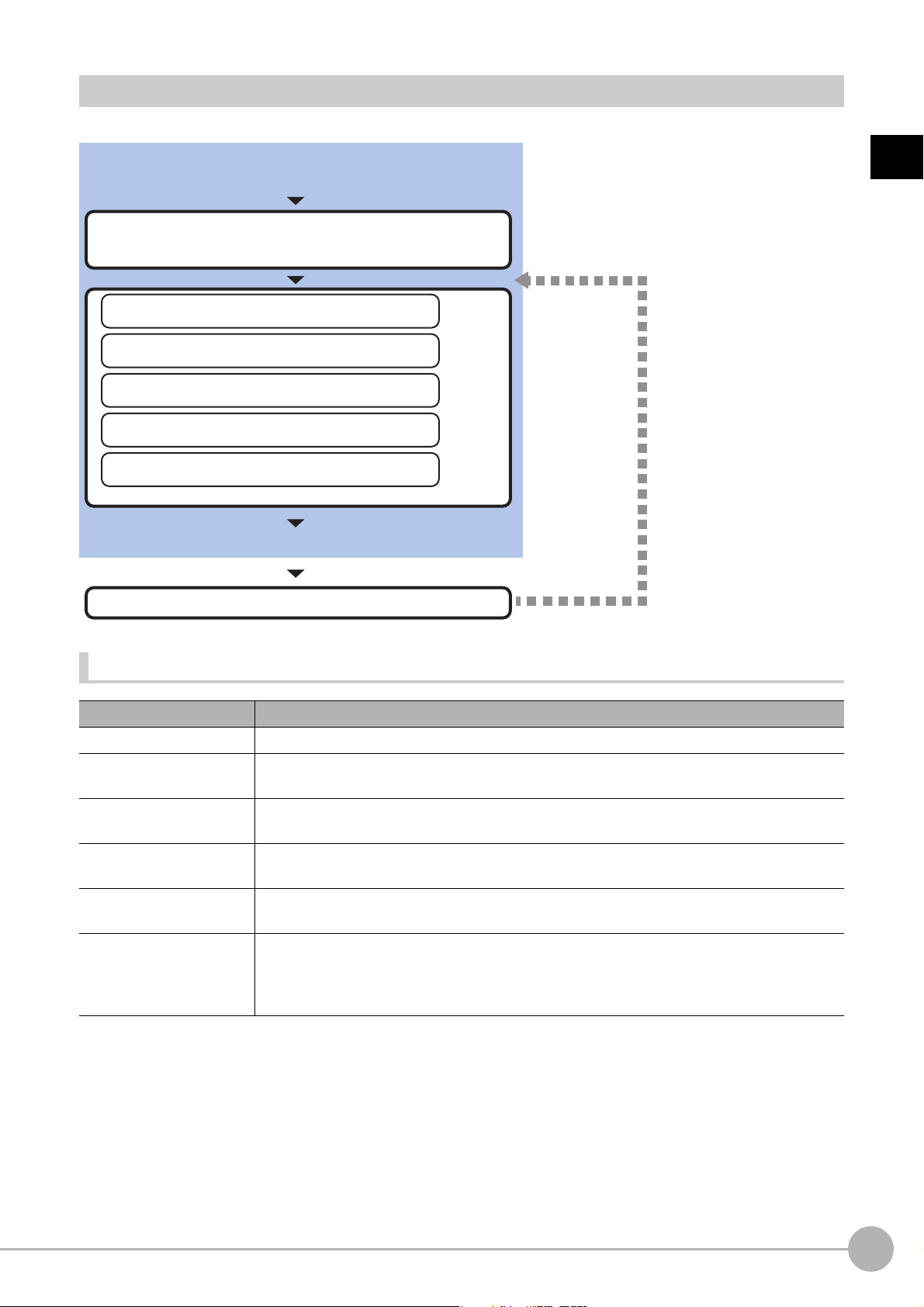
Settings Flow (Camera Image Input)
Perform as necessary
Select the camera to be set
*Be sure to perform settings when multiple cameras are used.
Results confirmation/adjustment
▲
Select Camera (Camera Image Input)
▲
Camera Settings (Camera Image Input)
▲
Screen Adjust Settings (Camera Image Input)
▲
White Balance (Camera Image Input)
▲
Calibration (Camera Image Input)
Start
Settings complete
Test measurement
To set camera image input, follow the steps below.
1
Input image
Camera Image Input Item List
Item Description
Camera 0 to 3 Select the camera to be set.
Select camera
Camera setting
Screen adjust
White balance
Calibration
When multiple cameras are connected, select the camera
Reference: Select Camera (Camera Image Input) (p.26)
Specify the camera settings such as the shutter speed or electronic flash.
Reference: Camera Settings (Camera Image Input) (p.26)
Adjust the lighting and the lens.
Reference: Screen Adjustment Settings (Ca
When using a color camera, adjust the white balance.
Reference: White Balance (Camera Image Input) (p.38)
Set when measurements (camera coordinate measuremen
actual dimensions. Select the calibration setting method and generate the calibration
parameters.
Reference: Calibration (Camera Image Input) (p.39)
to use for measurement.
mera Image Input) (p.30)
t valu
es) are to be output using
Camera Image InputFH/FZ5 Processing Item Function Reference Manual
25
Page 28
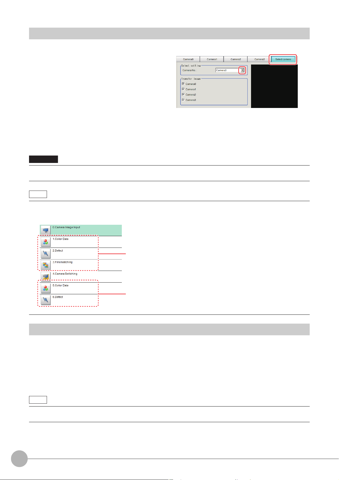
Select Camera (Camera Image Input)
Important
Note
The image selected through the [Select camera] option in the
[0 Camera Image Input] is the object to be measured.
The image selected through the [Select camera] option in the
[4 Camera Switching] is the object to be measured.
Note
When multiple cameras are connected, select the camera to use for measurement.
1 In the Item Tab area, click [Select camera].
2 Click [Camera No.] [ ] and select the camera number.
3 If multiple cameras are connected, the camera to transfer images for can be selected.
Unchecking the camera check box not being used for current Scene or logging, takt time will be shorten
because can reduce the transfer processing time after image input for that camera.
• Transfer of images for Camera 0 is executed at the same time as image input. Therefore, even if you uncheck the
checkbox for Camera 0, the image transfer time is not shortened.
• The image from the camera selected in [Select camera] will be
If you need to switch the camera during the process, insert a [Camera Swit
Reference: Camera Switching (p.83)
the object to be measured in the following units.
Camera Settings (Camera Image Input)
Set the following photographing conditions for each camera.
• Reference: Camera Settings (p.27)
• Reference: Frame/Field - for Monochrome Came
ching] unit in the scene and switch the image.
ras Only (p.28)
26
• Reference: Number of lines to be read (p.29)
• Reference: Electronic Flash Setting (p.30)
• The displayed items differ depending on the camera type and lighting mode. Perform the following procedure as
necessary in accordance with the use environment.
Camera Image Input
FH/FZ5 Processing Item Function Reference Manual
Page 29
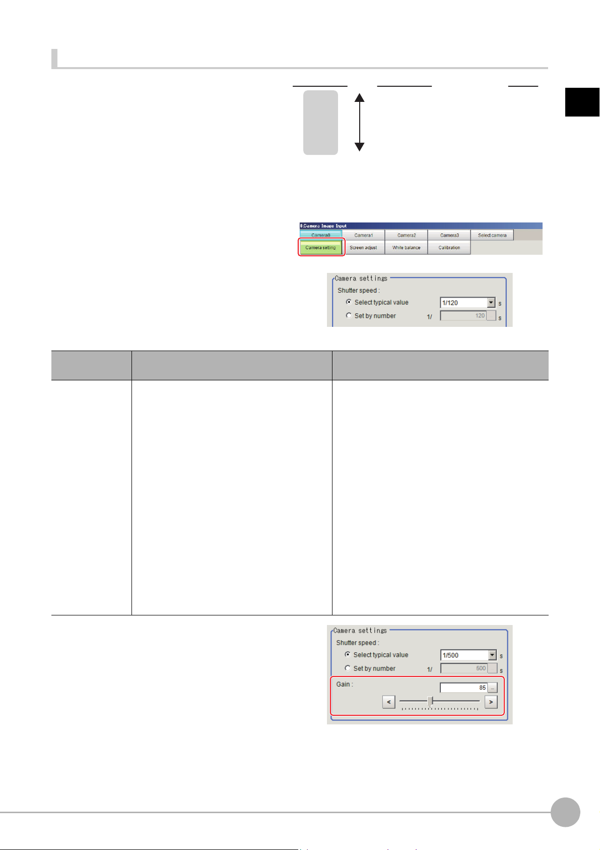
Camera Settings
Camera gain
[Factory defaults: 85]
200
0
Image quality Image
Very poor (too much noise)
Very good (less noise)
bright
dark
Adjust the settings related to camera shutter
speed and camera gain.
Select the shutter speed appropriate to the speed
e mea
of th
surement object. Choose a faster
shutter speed if the measurement object is
moving quickly and the image is blurred.
Adjust the camera gain when images cannot be
igh
tened through the shutter speed, lens
br
aperture, or lighting conditions. Usually, the
factory default value can be used.
1 In the Item Tab area, click [Camera
setting].
2 In the "Camera settings" area, specify
the shutter speed.
The setting methods are to select from the
options offered or to set the value directly.
1
Input image
Item
Shutter speed
FZ-SC/S/SHC/SH
• [Typical value]
1/200, [1/500], 1/1000, 1/2000, 1/4000,
1/8000, 1/20000
• Set by number
1/10 to 1/50000
FZ-SC2M/S2M/SC5M2/S5M2/SF/SP
• [Typical value]
1/200, [1/500], 1/1000, 1/2000, 1/4000,
1/8000, 1/20000
• Set by number
1/10 to 1/50000
FZ-SQ
• [Typical value]
1/200, 1/500, [1/1000], 1/2000, 1/4000,
1/8000, 1/16000, 1/30000
• Set by number
1/250 to 1/30000
Set value
[Factory default]
3 Specify the camera gain while checking
the image.
Description
Shutter speed value to set differs by camera type.
Camera Image InputFH/FZ5 Processing Item Function Reference Manual
27
Page 30
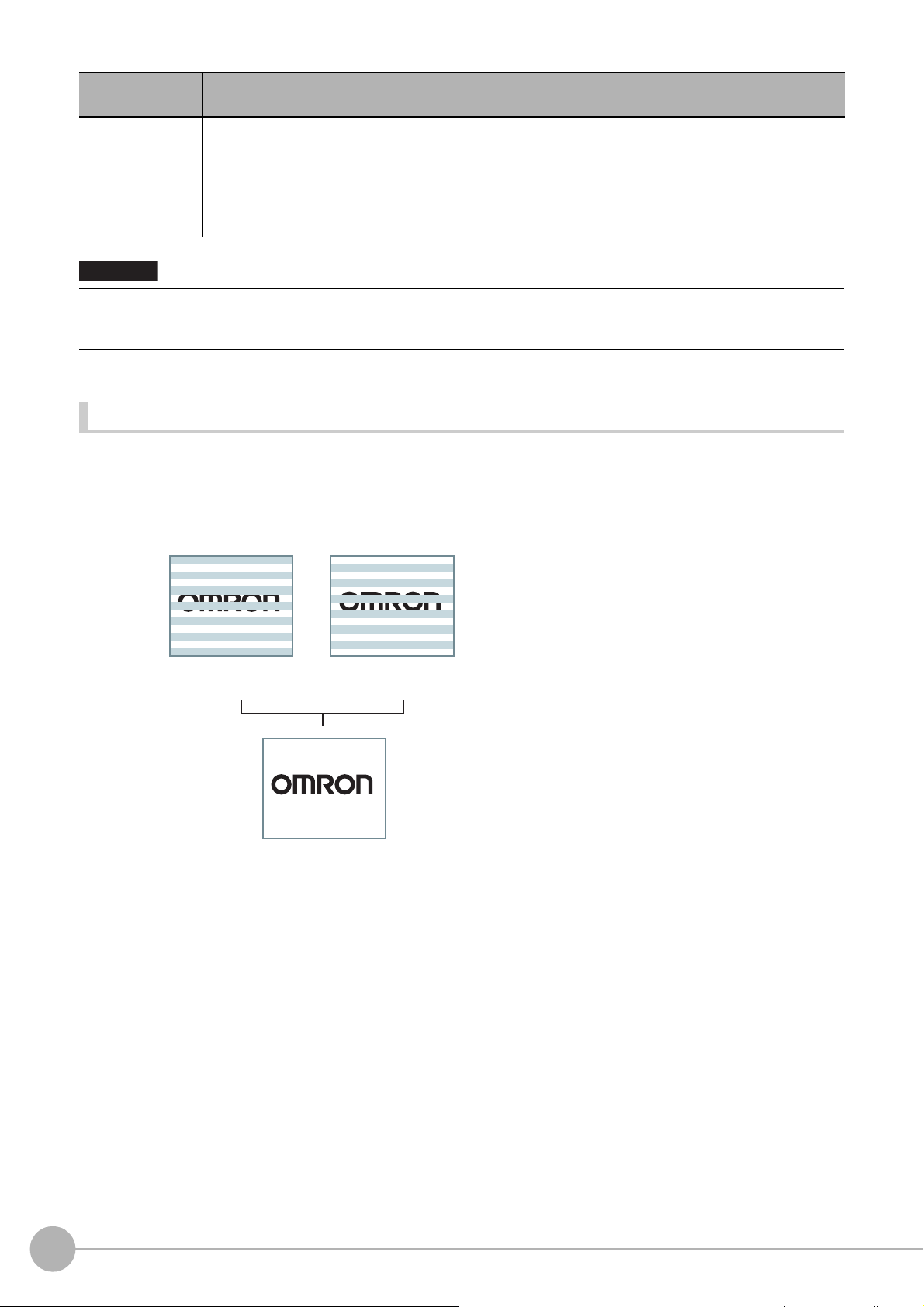
Item
Important
Field Image
Two field images are composed to make a
frame image.
Image with every other line
Odd scan lines
Resolution: 512 (H) × 242 (V) Resolution: 512 (H) × 242 (V)
Resolution: 512 (H) × 484 (V)
Even scan lines
Frame Image
• FZ-SC/S/SHC/SH
0 to 230 [85]
Gain
• When an Intelligent Compact Digital camera, FZ-SQ, is connected, we recommend setting the gain value to 16 for
st
able operations. Measurement values may be different if the recommended value is exceeded. Be sure to thoroughly
check the measurement result and set the gain value.
• FZ-SC2M/S2M/SC5M2/S5M2/SF□/SP□
0 to 230 [50]
•Z-SQ□□
16 to
□□
64 [16]
Set value
[Factory default]
Description
Adjust the camera gain when the shutter
speed, the len
conditions cannot be used to brighten the
image. Usually, the factory default value can
be used.
s aperture, and lighting
Frame/Field - for Monochrome Cameras Only
There are two methods to transfer one image from a camera to the sensor controller: frame read and field read.
Frame read is to read all of the scanned lines of the image. The result is called a frame image. Field read is used
to read half of the interlaced scanned lines of the image. The result is called the field image.
Here, select the unit to be treated as one image.
1 In the Item Tab area, click [Camera setting].
28
Camera Image Input
FH/FZ5 Processing Item Function Reference Manual
Page 31
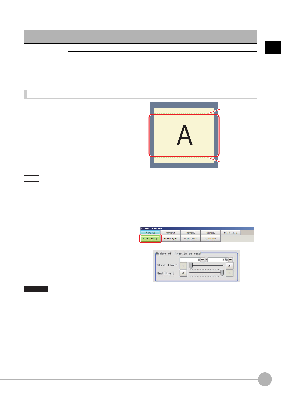
2 In the "Frame/Field" area, select either "Frame" or "Field".
Start line
End line
Image range
to be scanned
Note
Important
Item
Frame/Field
Set value
[Factory default]
[Frame] Measurements are done in frame units.
Measurements are done in field units. Select "Field" when you prefer shorter
image input time rather than higher accuracy.
Field
Processing becomes faster since each imag
line per two consecutive lines, but the measurement precision is decreased
because the vertical image resolution is lower.
Number of lines to be read
By narrowing the image range to be loaded, the image
scan time can be shortened.
Set the range taking the offset of the measurement
cons
object into
The part of the image narrowed down by the start line
and the end line will be displayed in the
ar
ea of the processing item setting window or the Main
screen.
ideration.
Image Display
Description
e is sca
1
Input image
nned skipping one scan
About minimum number of lines
• The minimum number of lines (minimum number of line
• For 5 megapixel cameras, the end line is fixed from 1921 to 2043.
About coordinate values
• The coordinate values displayed as the me
• The coordinate values do not vary according to the settings
asuremen
s
between start and end lines) is 12 lines.2043
t results are the values of the display position on the monitor.
for "Number of lines to be read".
1 In the Item Tab area, click [Camera
setting].
2 Set the start/end line in the "Number of
lines to be read" area.
• When the built-in lighting of an FZ-SQ is used, it may not be possible to shorten the processing time due to
restrictions on the light
emission time.
Camera Image InputFH/FZ5 Processing Item Function Reference Manual
29
Page 32

Electronic Flash Setting
Important
This function is set when an electronic flash is used. This sets the output conditions for the signal for
synchronizing the measurement and the electronic flash timing.
1 In the Item Tab area, click [Camera
setting].
2 In the "Electronic flash setting" area,
specify each item.
Item
STEP - STGOUT
delay
STGOUT width
STGOUT polarity
• Do not perform next camera image input processing before STGOUT signal output is completed. STGOUT signal
may not be output.
Perform camera image input processing after STGOUT signa
STEPSTGOUT delay and STGOUT pulse width so that the electronic flash operates synchronizing with the
exposure time.
• When you want the electronic flash to lite synchronously wi
the camera or the delay between STEP and STGOUT, taking into consideration the response time of the external
strobe controller.
Set value
[Factory default]
[0] t
o 511
(1 count 30μs)
1 to 63
[3]
(1 count 30μs)
• [Positive]
• Negative
Description
Set the waiting time from the time the STEP signal is input until the
electronic flash trigger output signal comes ON.
Delay Time = Count × 30μs + 90μs
The delay time depends on whether the STGOUT pulse polarity is
positive
The displayed time is for the positive polarity.
Add 35μs
The delay time can be set in a range of ±10μs from the sett
Set the output time for the electron
Select the pulse polarity of the electronic flash trigger.
Positive polarity: Flashes synchronized with the timing of the
flash trigger output signal changing from OFF to ON.
Negative: Flashes when the strobe trigger output signal changes from ON
to OFF.
or negative.
to the displayed time if the polarity is negative.
ic flash trigger signal.
tput completion, or set the STEP-camera delay,
l ou
th the exposure time, set the delay between STEP and
ing value.
electronic
30
Screen Adjustment Settings (Camera Image Input)
Set the lighting and lens conditions for each camera.
• Reference: Lighting Control (p.31)
• Reference: Line Bright (p.37)
Camera Image Input
FH/FZ5 Processing Item Function Reference Manual
Page 33

Lighting Control
When an Electronic flash controller or Camera-mount Lighting Controller is connected, the light volume of the
lighting can be adjusted from the sensor controller. Brightness can be adjusted automatically or one of the preset
patterns can be selected.
1 In the item tab area, click [Screen
adjust].
2 In the "Lighting control" area, specify the brightness.
Displayed contents differ depending on the connected camera, Electronic flash controller or Camara-mount
Lighting Controller.
Intelligent Compact Digital Camera FZ-SQ is connected:
1
Input image
Item Set value [Factory default] Description
Lighting on
Important
• When the lighting of FZ-SQ is used, there are following restrictions.
: The measurement can be longer than the
: There are restrictions in the opera
Reference: Multi-trigger Imaging (p.87)
Electronic flash controller FZ-LTA100 is co
• [Checked]
• Unchecked
measurement with the lighting OFF.
tion of Multi-trigger Imaging.
nnected:
Clear the checkbox when no lighting is to be
a
ed.
ppli
Camera Image InputFH/FZ5 Processing Item Function Reference Manual
31
Page 34

Electronic flash controller FZ-LTA200 is connected:
0 +1CH are used: 0CH is used: 1CH is used:
Item Set value Description
Pattern select Pattern 0 to 16 Can be selected from a preset lighting pattern.
When 1 channel is used, the light volume ca
Brightness at
ch
part
ea
0 to 255
[0]
Camera-mount Lighting Controller FLV-TCC1 is
Item Set value Description
Pattern select
On all the time
Modulate mode
Part
0 to 255
[128]
--- Select from preset lighting patterns.
• Checked
•[Unchecked]
•[Duty]
• Voltage /
Curre
nt
When 2 channels are used, the light volume can be adjusted to one of 128
levels. 0 indicates the lighting is OFF. The larger the number, the higher the
brightness.
connected:
Place a check here to keep the light turned ON
exposure time.
Select the lighting adjustment method.
•Duty
The brightness of the light is adjusted with
frequency: 100 kHz).
• Voltage / Current
The brightness of the light is adjusted
Select voltage lighting adjustment if you will use a hig
Set the brightness for the selected parts.
djusted to one of 256 levels.
n be a
all of the time regardless of the
255 levels of the pulse width (PWM
with 255 voltage / current levels.
h-speed shutter speed.
32
Camera Image Input
FH/FZ5 Processing Item Function Reference Manual
Page 35
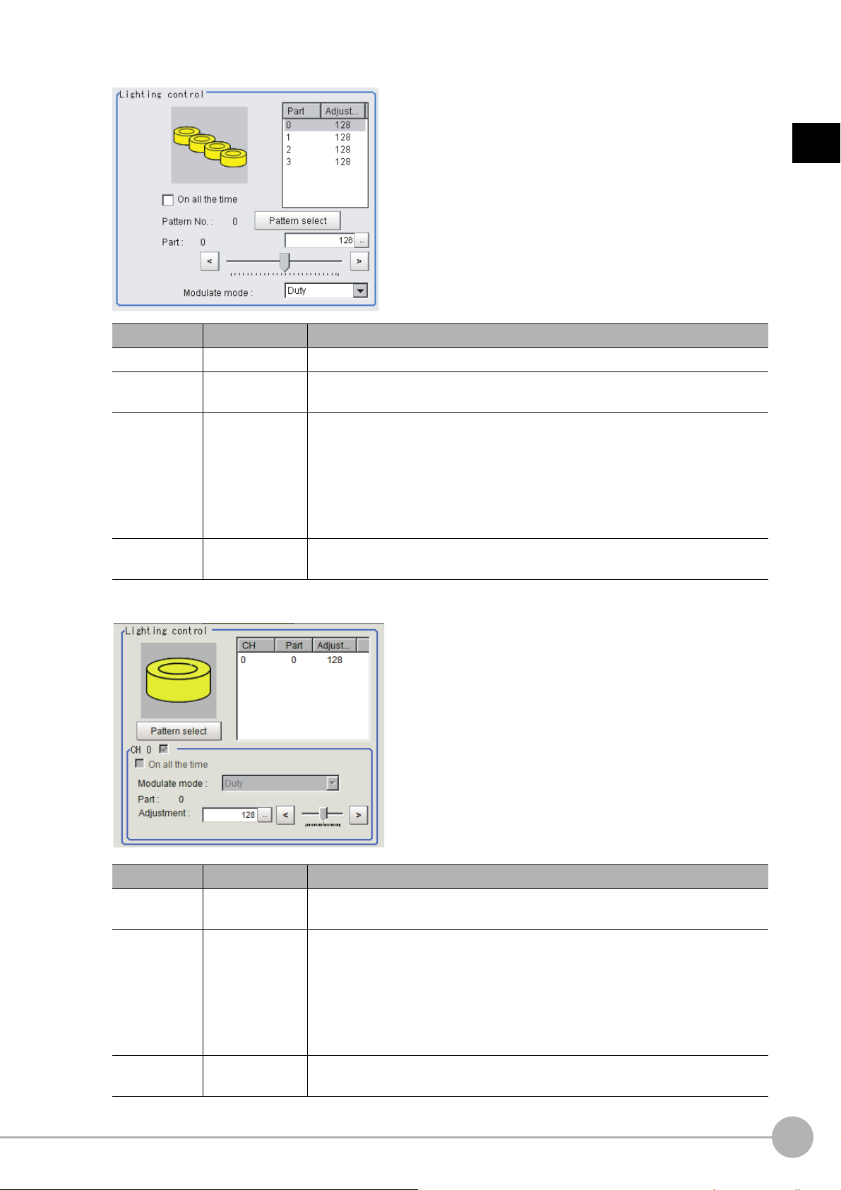
Camera-mount Lighting Controller FLV-TCC4 is connected:
Item Set value Description
Pattern select
On all the time
Modulate mode
Part
0 to 255
[128]
--- Select from preset lighting patterns.
• Checked
•[Unchecked]
•[Duty]
• Voltage /
Curre
nt
Place a check here to keep the light turned ON all of the time regardless of the
exposure time.
Select the lighting adjustment method.
•Duty
The brightness of the light is adjusted with
frequency: 100 kHz).
• Voltage / Current
The brightness of the light is adjusted
Select voltage lighting adjustment if you will use a hig
Set the brightness for the selected parts.
255 levels of the pulse width (PWM
with 255 voltage / current levels.
h-speed shutter speed.
1
Input image
Camera-mount Lighting Controller FLV-TCC1EP is connected:
Item Set value Description
On all the time
Modulate mode
• Checked
•[Unchecked]
•[Duty]
• Voltage /
Curre
nt
Place a check here to keep the light turned ON
exposure time.
Select the lighting adjustment method.
•Duty
The brightness of the light is adjusted with
frequency: 100kHz).
• Voltage / Current
The brightness of the light is adjusted
Select voltage / current adjustment if you will use a high-speed shutter speed.
with 255 voltage / current levels.
all of the time regardless of the
255 levels of the pulse width (PWM
Part
0 to 255
[128]
Set the brightness for the selected parts.
Camera Image InputFH/FZ5 Processing Item Function Reference Manual
33
Page 36
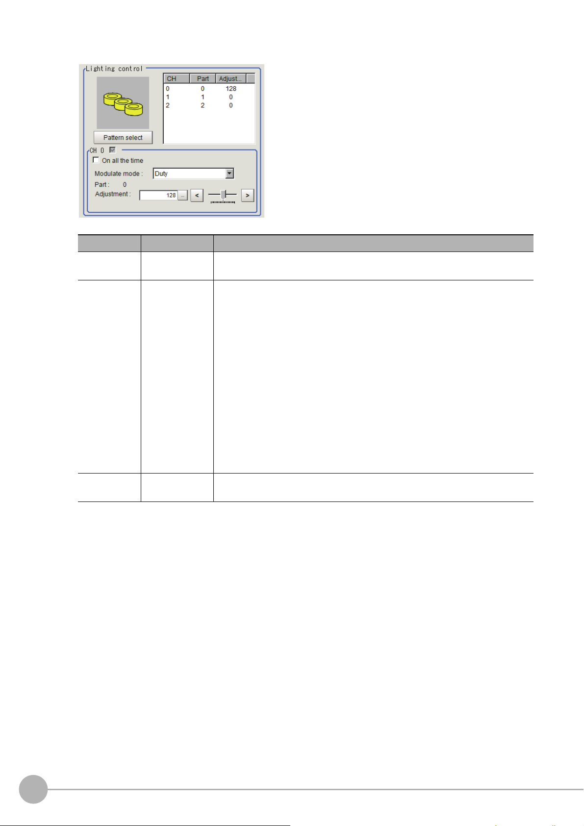
Camera-mount Lighting Controller FLV-TCC3HB is connected:
Item Set value Description
On all the time
Modulate mode
Part
• Checked
•[Unchecked]
•[Duty]
• Voltage /
Curre
nt
0 to 255
[128]
Place a check here to keep the light turned ON
exposure time.
Select the lighting adjustment method.
0ch connected:
•Duty
The brightness of the light is adjusted with
frequency: 100kHz).
• Voltage / Current
The brightness of the light is adjusted
0ch is the channel for the spot lighting.
1ch / 2ch connected:
•Duty
The brightness of the light is adjusted with
frequency: 100kHz).
• Voltage / Current
The brightness of the light is adjusted
Select voltage / current adjustment if you will use a high-speed shutter speed.
Set the brightness for the selected parts.
with 255 voltage / current levels.
with 255 voltage / current levels.
all of the time regardless of the
255 levels of the pulse width (PWM
255 levels of the pulse width (PWM
34
Camera Image Input
FH/FZ5 Processing Item Function Reference Manual
Page 37

Important
Total powe r
consumption
Power consumption
per channel
Connectability
Lighting mode
*1
READY OFF
time delay
*2
Always-on
lighting mode
Simultaneous
lighting mode
Single lighting
mode
Greater than
7.5 W
Greater than 7.5 W Not connectable --- --- --- ---
7.5 W or less Connectable NA NA OK None
7.5 W or less Less than 7.5 W Connectable OK OK OK None
Total powe r
consumption
Power consumption
per channel
Connectability
Lighting mode
*1
READY OFF
time delay
*2
Always-on
lighting mode
Simultaneous
lighting mode
Single lighting
mode
Greater than
15 W
Greater than 15 W Not connectable --- --- --- ---
15 W or less Connectable NA NA OK Yes
7.5 W or less Connectable NA NA OK None
15 W or less
Less than 15 W Connectable NA OK OK Yes
7.5 W or less Connectable NA OK OK Yes
7.5 W or less Less than 7.5 W Connectable OK OK OK None
Total powe r
consumption
Power consumption
per channel
Connectability
Lighting mode
*1
READY OFF
time delay
*2
Always-on
lighting mode
Simultaneous
lighting mode
Single lighting
mode
Greater than
7.5 W
Greater than 7.5 W Not connectable --- --- --- ---
7.5 W or less Connectable NA NA OK None
7.5 W or less Less than 7.5 W Connectable OK OK OK None
Total powe r
consumption
Power consumption
per channel
Connectability
Lighting mode
*1
READY OFF
time delay
*2
Always-on
lighting mode
Simultaneous
lighting mode
Single lighting
mode
Greater than
5.5 W
Greater than 7.5 W Not connectable --- --- --- ---
7.5 W or less Connectable NA NA OK None
5.5 W or less Less than 5.5 W Connectable OK OK OK None
• There is no restriction on power consumption nor on lighting mode when using lightings with lighting controller
FLV-TCC1EP. Restrictions on power consumption and lighting mode differ depending on the product series. See
the following table for details.
1
1. FLV-TCC4/-TCC1
• Without external power supply
• With external power supply
Input image
2. FLV-TCC3HB
• Without external power supply
0ch (spot lighting) not connected
0ch (spot lighting) connected
Camera Image InputFH/FZ5 Processing Item Function Reference Manual
35
Page 38

• With external power supply
Total powe r
consumption
Power consumption
per channel
Connectability
Lighting mode
*1
READY OFF
time delay
*2
Always-on
lighting mode
Simultaneous
lighting mode
Single lighting
mode
Greater than
15 W
Greater than 15 W Not connectable --- --- --- ---
15 W or less Connectable NA NA OK Yes
7.5 W or less Connectable NA NA OK None
15 W or less
Less than 15 W Connectable NA OK OK Yes
7.5 W or less Connectable NA OK OK Yes
7.5 W or less Less than 7.5 W Connectable OK OK OK None
Total powe r
consumption
Power consumption
per channel
Connectability
Lighting mode
*1
READY OFF
time delay
*2
Always-on
lighting mode
Simultaneous
lighting mode
Single lighting
mode
Greater than
14 W
Greater than 15 W Not connectable --- --- --- ---
15 W or less Connectable NA NA OK Yes
7.5 W or less Connectable NA NA OK None
14 W or less
Less than 14 W Connectable NA OK OK Yes
7.5 W or less Connectable NA OK OK Yes
5.5 W or less Less than 5.5 W Connectable OK OK OK None
Always-on
lighting mode
In this mode, the lights are always turned ON for a specific pulse cycle. The always-on lighting mode is
used if you place a check in “On all the time” in the “Lighting control” area.
Simultaneous
lighting mode
In this mode, all of the connected lights are turned ON in synchronization with the trigger. Set the
“Adjustment” set values in the “Lighting control” area for each light to any value other than 0 for all of
the parts.
Single
lighting mode
In this mode, only one of the connected lights is turned ON in synchronization with the trigger. Set the
“Adjustment” set value in the “Lighting control” area to any value other than 0 for the part for only one
channel. The lights will not turn ON if you set two or more channels to an adjustment other than 0.
0ch (spot lighting) not connected
0ch (spot lighting) connected
*1: Lighting modes
*2: Turning OFF the READY signal is delayed in comparison with not connecting a camera with lighting controller by
approximat
ely the exposure time.
Example: Connection example for connecting an external power supply and the lighting modes
• If four lights with a power consumption of 1 W each a
re connected to a camera with lighting controller,
always-on lighting, simultaneous lighting, and single lighting are all possible.
• If four lights with power consumptions of 2 W, 3 W, 4 W
and 5 W are connected to a camera with lighting
,
controller, simultaneous lighting and single lighting are possible.
• If four lights with power consumptions of 12 W, 1 W, 2 W
and 1 W are connected to a camera with lighting
,
controller, only single lighting is possible.
36
Camera Image Input
FH/FZ5 Processing Item Function Reference Manual
Page 39

Line Bright
R, G, B graph lines
Max. density value (red)
Indicates the max. density value.
Coordinate axis (yellow)
This line is moved to the location in which
density is to be checked.
The graph showing the gray distribution for 1 line in the image is called the "Line bright". You can display the line
brights for R, G and B for any horizontal or vertical line.
1 In the item tab area, click [Screen
adjust].
2 Select the [Display line bright] check
box.
3 Move the line to the position
whose density distribution you
want to see.
1
Input image
Camera Image InputFH/FZ5 Processing Item Function Reference Manual
37
Page 40

White Balance (Camera Image Input)
Note
Note
Set the white balance to make white objects look white by calibrating the color of images loaded from cameras.
By adjusting the white balance, the appropriate white color can
be reproduced under any lighting conditions
Appropriate values can also be set automatically.
• Perform the white balance setting only when a color camera is used.
• In the following cases, make sure to perform white balance.
• When a new system is inst
When the camera or lighting is changed
•
Since measurement results may vary with changes of the white balance setting, be sure to verify the operation after it has changed.
alled
1 In the Item Tab area, click [White
balance].
2 Shoot a white piece of paper or cloth.
3 Click [Auto].
• When the "Too bright" or "Too dark" message is displayed, adjust the iris, shutter speed, gain and/or lighting
conditions until "Automatic adjustment is possible" is displayed.
4 Adjust the "R", "G" and "B" values as necessary.
Item
White balance setting
•R
•G
•B
R, G, and B: 0.001 to 7.999
FZ-SQ: 0.001 to 3.000
•FZ-SC
[R=1.183]
[G=1.000]
[B=1.323]
•FZ-SC2M
[R=1.394]
[G=1.000]
[B=1.222]
•FZ-SHC
[R=1.375]
[G=1.000]
[B=1.452]
• FZ-SFC and FZ-SPC
[R=1.145]
[G=1.000]
[B=1.889]
•FZ-SC5M2
[R=1.351]
[G=1.000]
[B=2.314]
•FZ-SQ
[R=1.000]
[G=1.040]
[B=1.800]
Set value
[Factory default]
Description
Adjust the white balance.
Whiteness increases when the value of "R",
"G",
and "B" is increased.
38
Camera Image Input
FH/FZ5 Processing Item Function Reference Manual
Page 41

Calibration (Camera Image Input)
Note
Note
By setting the calibration, the measurement result can be converted and output as actual dimensions. The
calibration method is selected here.
There are three calibration methods, point, sampling, and parameter.
• Reference: Specifying Points and Setting (Point Specification) (p.39)
1
Input image
• Reference: Setting Calibration through Sampling Measurement (Samp
ling) (p.40)
• Reference: Inputting and Setting Values (Value Setting) (p.42)
• Reference: View Calibration Parameters (p.43)
• In order to output measurement results in actual dimensions, set [Calibration] to "ON" in [Output parameter] for each
processing unit. If [Calibration] is "OFF" (factory default), measurement results are output as camera image coordinate
values.
Specifying Points and Setting (Point Specification)
This is a method for performing calibration by specifying arbitrary points (in pixels).
Calibration parameters are calculated automatically when actual
Up to 3 points can be specified.
• When magnification is the same in
the X and Y directions
Specify only 2 points.
X : Y = 1 : 1
• When magnification is not the same in the X and
Y directions
Specify 3 points.
X : Y = 5 : 3
coordinates of specified locations are entered.
Calibration
• When 2 points are specified, the coordinate system is set to the left-hand system (forward in the clockwise direction).
Specify 3 points to perform calibration including the coordinate system.
X : Y = 1 :
Calibration
X : Y = 1:
1 In the Item Tab area, click [Calibration].
2 In the "Calibration setting" area, select
"Specify point".
3 Click the first point on the screen.
Camera Image InputFH/FZ5 Processing Item Function Reference Manual
39
Page 42
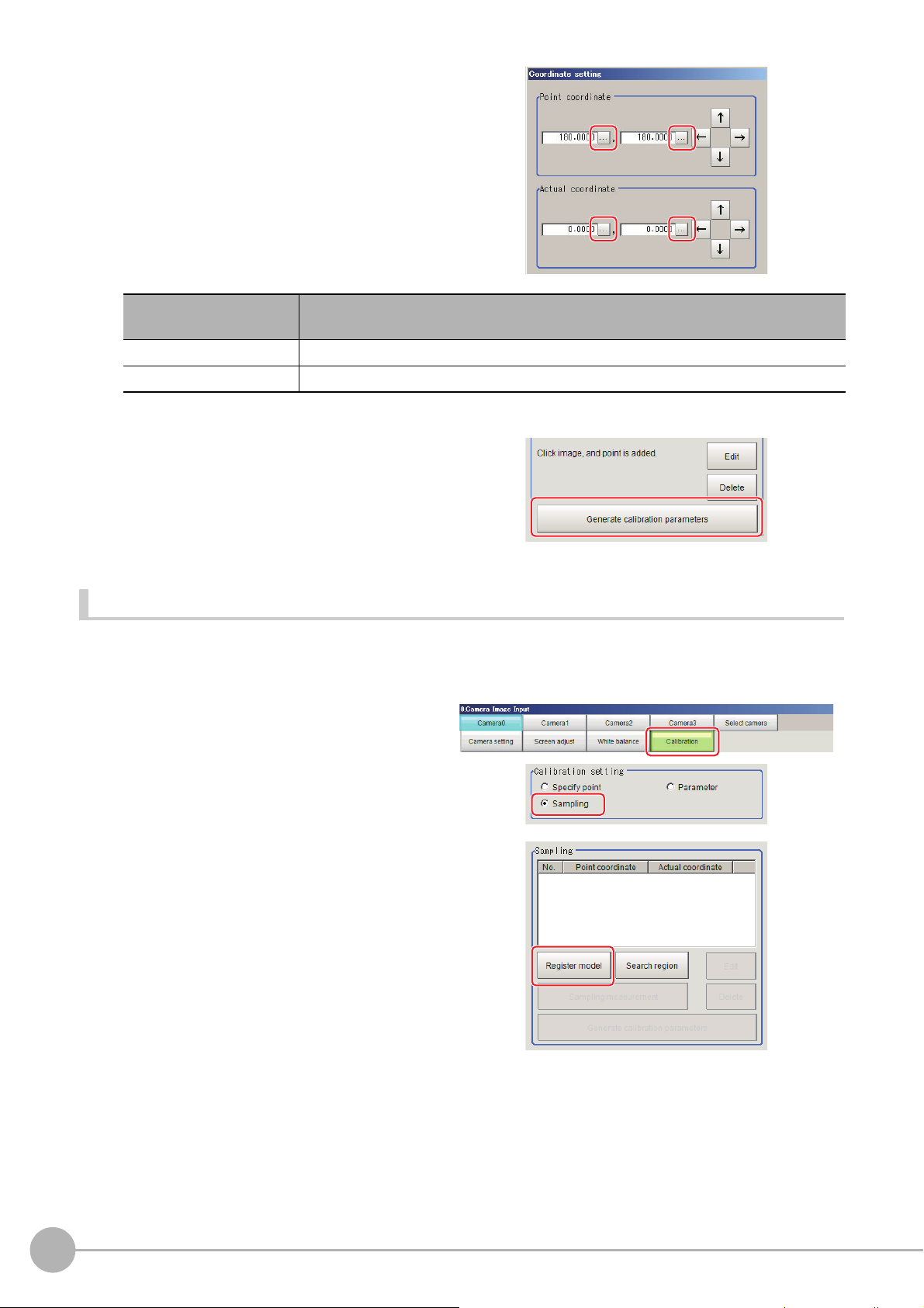
4 Input the actual coordinates for the
specified point.
The actual coordinate input window is
displayed.
Actual coordinate
Point coordinate X, Y 0 to 9999.9999 [Point you clicked in the window]
Actual coordinate X, Y -99999.9999 to 99999.9999 [0]
Set value
[Factory default]
5 Set the 2nd and 3rd points in the same way.
6 Click [Generate calibration parameters].
The calibration parameters will be generated.
Setting Calibration through Sampling Measurement (Sampling)
This is a method for setting calibration based on measurement results.
Calibration parameters are calculated automatically wh
coordinates for that position entered.
en a registered model is searched and the actual
1 In the Item Tab area, click [Calibration].
2 In the "Calibration setting" area, select
"Sampling".
3 In the "Sampling" area, click [Regist
model].
4 Use the Drawing tools to register the
model.
5 Adjust the search region as necessary.
The default value setting is for the entire
screen.
40
Camera Image Input
FH/FZ5 Processing Item Function Reference Manual
Page 43

6 Click [Sampling measurement].
Measurement is performed.
The search result (cross-shaped cu
displayed in the Image Display area, and the
Sampling Coordinate window is displayed.
rsor) is
7 In the Sampling Coordinate window,
enter the X and Y values.
8 Click [OK].
Point coordinates and actual coordinates are
registered in the "Sampling" area.
9 Move the object to be measured and repeat the Steps Reference: 3 (p.40) to Reference: 8
(p.41).
1
Input image
10 Click [Generate calibration parameters].
The calibration parameters will be generated.
Camera Image InputFH/FZ5 Processing Item Function Reference Manual
41
Page 44

Inputting and Setting Values (Value Setting)
Lefthanded
Righthanded
X
Y
0
0
Positive
X
Y
Positive
Upper left of screen
Lower left of screen
Center of screen
Enter calibration data directly with numerical values.
1 In the Item Tab area, click [Calibration].
2 In the "Calibration setting" area, select
"Parameter".
3 In the "Parameter" area, specify values
for the "Coordinate", "Origin" and
"Magnification".
Item
Coordinate
Origin
Set value
[Factory default]
• [Lefthand]
• Righthand
• [Upperleft]
• Lowerleft
•Center
Description
Left-hand type: Clockwise is forward
when
specifying the coordinates.
Right-hand type: Counter-clockwise is
forward when
Select where the origin of the
actual
specifying the coordinates.
rdinates will be.
coo
4 Click [Generate calibration parameters].
42
Camera Image Input
Magnification 0.00001 to 9.99999 Specify the ratio of 1 pixel to the
The calibration parameters will be generated.
FH/FZ5 Processing Item Function Reference Manual
actual dimensions.
Page 45
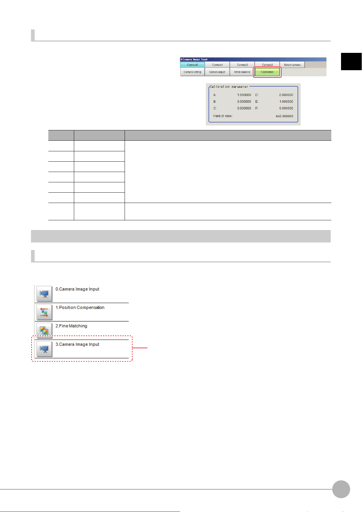
View Calibration Parameters
Position compensation of unit 1 is canceled and returns to the
position before position compensation.
View the set calibration data.
1 In the Item Tab area, click [Calibration].
2 In the "Calibration parameter" area,
confirm the calibration data.
Item Set value Description
A Calculation value
B Calculation value
C Calculation value
D Calculation value
E Calculation value
F Calculation value
Field of
view
Calculation value This is an actual dimension in the X direction.
These are calibration conversion values. Camera coordinates are converted to actual
inates base
coord
are as follows:
• (X, Y): Measurement point (camera coordinates), Unit: pix
• (X', Y'): Conversion point (actual coordinates)
X'=A ×
X + B × Y
Y'=D × X + E ×
1
Input image
d on these values. The conversion formulas for actual coordinates
+ C
Y + F
Additional Explanation (Camera Image Input)
Position Compensation and Camera Image Input
When creating a scene, if a [Camera Image Input] unit is positioned after a [Position Compensation] processing
unit, that [Position Compensation] unit will be cancelled, which will cause a new image to be read.
Camera Image InputFH/FZ5 Processing Item Function Reference Manual
43
Page 46

Camera Image Input FH
Camera
- Shutter speed
- Camera gain
- Calibration
[Camera settings]
Sensor controller
Important
Important
This is a processing item specific to the FH Sensor Controller.
Set the conditions for loading images from the camera and for storing images of the measured objects. This
processing item mu
In addition, it is possible to shoot images whose shutter
Image Input to your flow.
Used in the Following Case
st be used when measuring.
sp
eed, or lighting differ by setting multiple Camera
• [Camera Image Input FH] is preset for Unit 0. Do not set any processing item other than camera image input (camera
image input FH, camera image input HDR, camera image input HDR Lite) for Unit 0.
• When switching from a color camera to a monochrome or switchi
the settings in the following units.
• If a camera is connected other than the one
settings.
• Immediately after starting up the FH Sensor Controller and
image. No input image is processed as the same color image as in the factory default state.
• If you open the Properties Dialog Box before inputting an image, cli
the OK button in the dialog box will change the setting to the same color camera setting as the factory default setting.
(Reference: "FAQ For Measurement The measurement NG (image
monochrome camera" in the "Vision System FH/FZ5 Series User's Manual (Z365)")
• When the Scene data created via FZ series Sensor
automatically converted to [Camera Image Input FH].
• The automatically converted conten
FH]. The other settings is set to the default settings of the connected camera to the FH-1000, FH-3000, or FH-L series
Sensor Controller.
• When you load the created data via FH series Sencor Controller
Sensor Controller, the automatically conversion is not performed.
s is the common items between [Camera Image Input] and [Camera Image Input
t
for the previous settings, the camera settings are returned to their initial
immediately after changing scenes, there will be no input
Controller, i.e. FZ5 series or FZ5-L series, [Camera Image Input] is
to a camera with a different resolution, reconfigure
ng
k the Cancel button to close the dialog box. Pressing
c
mismatch) error will result when connecting a
, i.e. FH-L series or FH-1000 series. via FZ series
44
Camera Image Input FH
FH/FZ5 Processing Item Function Reference Manual
Page 47
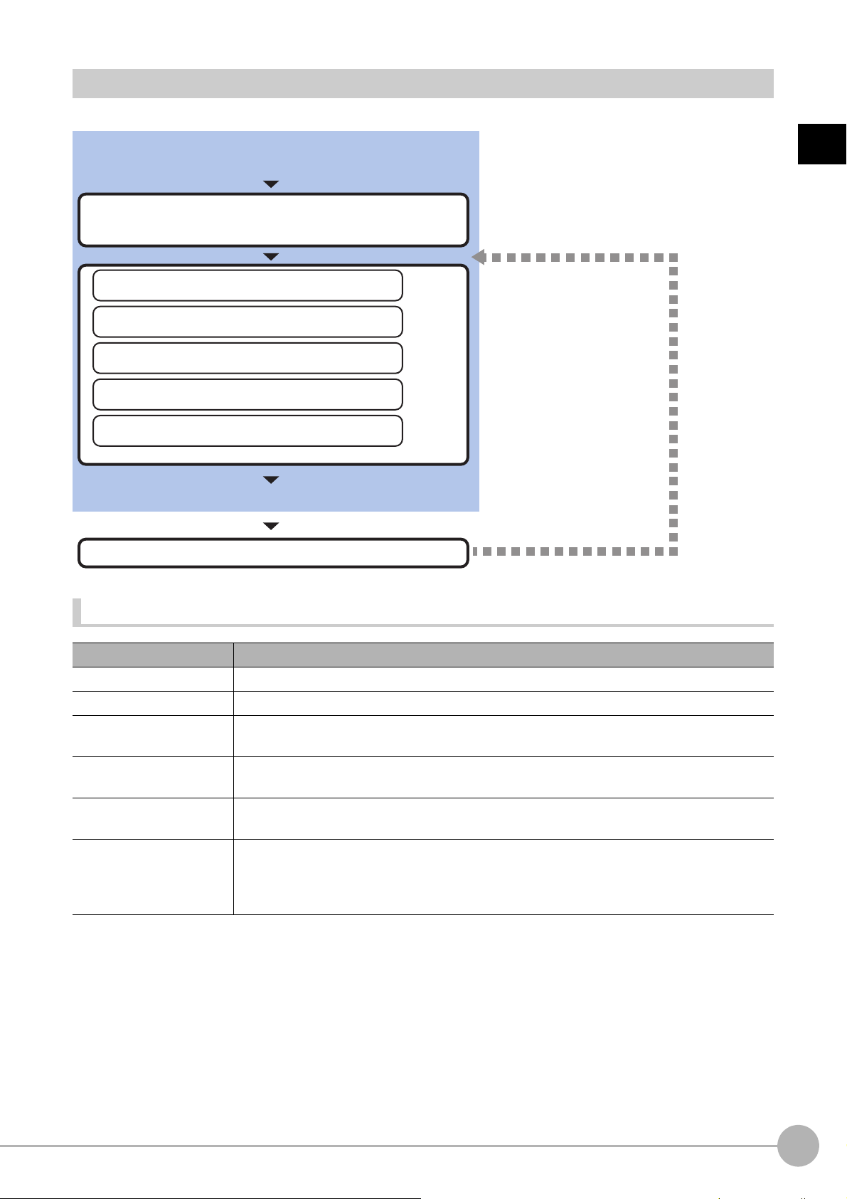
Settings Flow (Camera Image Input FH)
Set as necessary.
Select the camera to set
*Always do this when using multiple cameras
Check results/make adjustments
▲
Camera Selection (Camera Image Input FH)
▲
Camera Settings (Camera Image Input FH)
▲
Screen Adjust Settings (Camera Image Input FH)
▲
White Balance (Camera Image Input FH)
▲
Calibration (Camera Image Input FH)
Start
Settings complete
Test measurement
To set camera image input, follow the steps below.
1
Input image
List of Camera Image Input FH Items
Item name Description
Camera 0 to 7 Select the camera to be set.
Select camera When multiple cameras are connected, select the
Camera setting
Screen adjust
White balance
Calibration
camera
to use for measurement.
Specify the camera settings such as the shutter speed or electronic flash.
Reference: Camera Settings (Camera Image Input FH) (p.46)
Set the adjustment of the lighting and the lens.
Reference: Screen Adjustment Settings (Camera Image Input FH) (p.54)
When using a color camera, set the white balance.
Reference: White Balance (Camera Image Input FH) (p.64)
Set when measurements (camera coordinate measuremen
t values) are to be output using
actual dimensions. Select the calibration setting method and generate the calibration
parameters.
Reference: Calibration (Camera Image Input FH) (p.66)
Camera Image Input FHFH/FZ5 Processing Item Function Reference Manual
45
Page 48

Camera Selection (Camera Image Input FH)
Important
Note
The image selected through the [Select camera]
option in the [0 Camera Image Input] is the object
to be measured.
The image selected through the [Select camera]
option in the [4 Camera Switching] is the object to
be measured.
Note
When multiple cameras are connected, select the camera to use for measurement.
1 In the Item Tab area, click [Select camera].
2 Click [Camera No.] [ ] and select the
camera number.
3 If multiple cameras are connected, the
camera to transfer images for can be selected.
Unchecking the camera check box not being used for current Scene or logging, takt time will be shorten
because can reduce the transfer processing time after image input for that camera.
• Transfer of images for Camera 0 is executed at the same time as image input. Therefore, even if you uncheck Camera 0,
the image transfer time is not shortened.
• The image from the camera selected in [Select camera] will be
If you need to switch the camera during the process, insert a [Camer
Reference: Camera Switching (p.83)
the object to be measured in the following units.
a Switching] unit in the scene and switch the image.
Camera Settings (Camera Image Input FH)
Set the following photographing conditions for each camera.
• Reference: Camera Settings (p.47)
• Reference: Binning Settings (for Monochrome Cameras Only) (p.51)
• Ref
erence: Number of lines to be read (p.51)
46
• Reference: Electronic Flash Setting (p.52)
• The displayed items differ depending on the camera type and lighting mode. Specify the setting for the following
procedure as necessary in accordance with the use environment.
Camera Image Input FH
FH/FZ5 Processing Item Function Reference Manual
Page 49
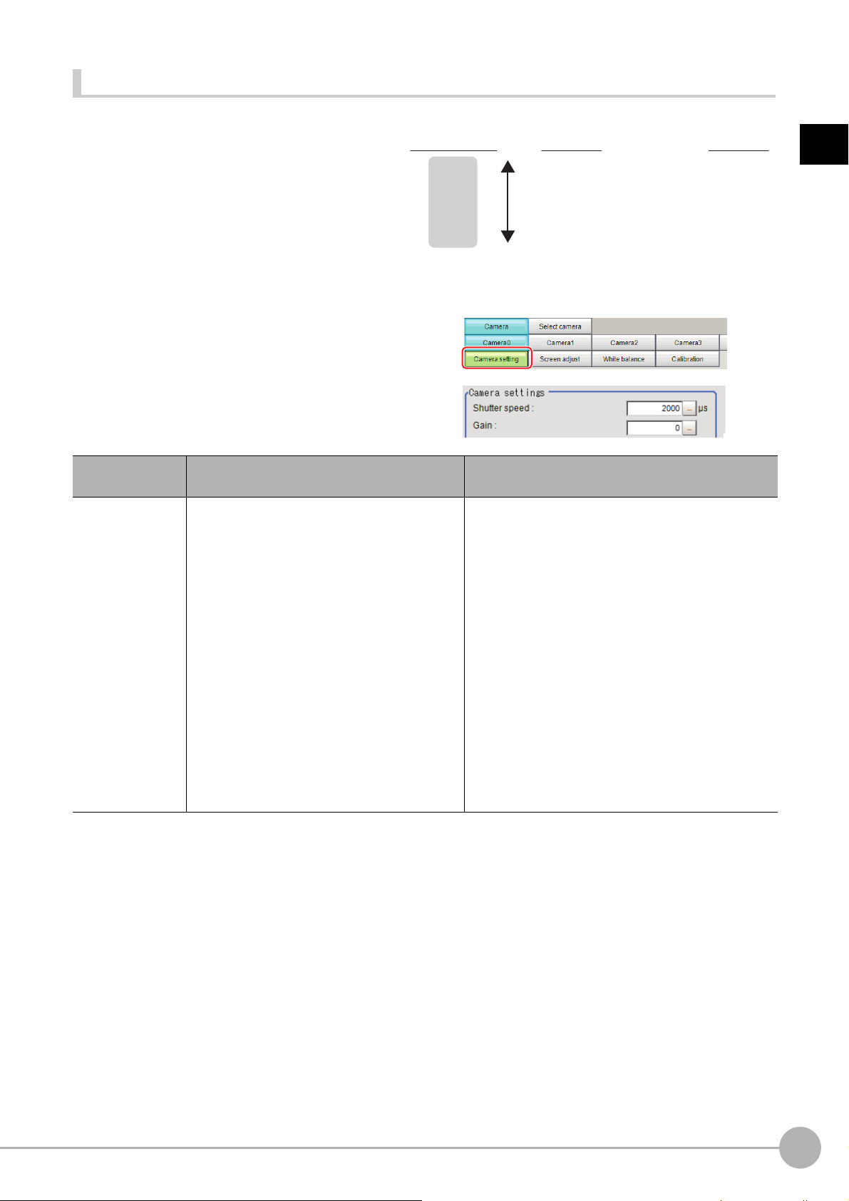
Camera Settings
Camera gain
(Factory default: 85)
230
0
Screen Image
Bad (noise increases)
Good (noise decreases)
Bright
Dark
Example Using the FZ-SC
Adjust the settings related to camera shutter
speed and camera gain.
Set the shutter speed appropriate to the speed of
e
measurement object. Choose a faster shutter
th
speed if the measurement object is moving
quickly and the image is blurred.
Adjust the camera gain when images cannot be
igh
tened through the shutter speed, lens
br
aperture, or lighting conditions. Usually, the
factory default value can be used.
1 In the Item Tab area, click [Camera
setting].
2 In the "Camera settings" area, specify
the shutter speed.
1
Input image
Item
Shutter speed
Setting value
[Factory default]
• FZ-SC/S/SHC/SH
20 to 100000 [μs]
[2000]
• FZ-SC2M/S2M/SC5M2/S5M2/SF□/SP□
20 to 100000 [μs]
[8333]
•FZ-SQ□□
35 to 4000 [μs]
[1000]
• FH-SC02/SM02/SC04/SM04
25 to 100000 [μs]
[2000]
• FH-SC05R/SM05R
500 to 100000 [μs] by 50
[80
•FH-SC12/SM12
60 to 100000 [μs]
[12000]
□□
μs unit
00]
Description
Shutter speed value to set differs by camera type.
Camera Image Input FHFH/FZ5 Processing Item Function Reference Manual
47
Page 50

3 Specify the camera gain while checking
Important
the image.
Item
• FZ-SC/S/SHC/SH
0 to 230 [85]
• FZ-SC2M/S2M/SC5M2/S5M2/SF□/SP□
0 to 230 [50]
Gain
• When an Intelligent Compact Digital camera, FZ-SQ□□
stable operations. Measurement values may be different if the recommended value is exceeded.
Be sure to thoroughly check the measurement result and set the gain value.
• Due to the specification of its imaging elements, a CMOS camera gen
camera is raised. You may also find multiple defective pixels, but they do not represent a defect or failure of the product
in any way. If stripe noises and defective pixels affect the measurement results, lower the gain setting of the camera or
use a CCD camera.
•FZ-SQ□□□□
16 to 64 [16]
• FH-SC02/SM02/SC04/SM04/SC12/SM12
0 to 255 [0]
• FH-SC05R/SM05R
0 to 63 [0]
Setting value
[Factory default]
Description
Adjust the camera gain when the shutter speed, the
le
ns aperture, and
to brighten the image.
Usually, the factory default value can be used.
□□, is
connected, we recommend setting the gain value to 16 for
erates stripe noises when the gain setting of the
lighting conditions cannot be used
48
Camera Image Input FH
FH/FZ5 Processing Item Function Reference Manual
Page 51

Reset Mode (FH-SC05R/FH-SM05R only)
Important
Trigger Timing
Time
Line1
Line2
Line3
Line4
Line5
::
::
Line N-2
Line N-1
Line N
Strobe Lighting Time
Exposure Time
Exposure Time
Exposure Time
Exposure Time
Exposure Time
Exposure Time
Exposure Time
Exposure Time
• Although the exposure start timing differs between
lines, the exposure time length is the same between
the lines.
• Since the exposure start timing is different, please
control so that the strobe lighting time is from the
start of exposure of Line 1 until completion of
exposure of Line N.
• The formula for strobe lighting time is that it should
be the difference between exposure time + (number
of lines -1) x 1 line timing.
• The number of lines depends on the Number of lines
to be read setting.
• The timing difference between 1 line varies
depending on the binning setting.
With Binning 1 line setting: 36.375μs
With Binning 2 line setting: 43.583μs
Timing difference between 1 line
Trigger Timing
Time
Line1 Exposure Time
Line2 Exposure Time
Line3 Exposure Time
Line4 Exposure Time
Line5 Exposure Time
::
::
Line N-2 Exposure Time
Line N-1 Exposure Time
Line N Exposure Time
• Exposure for all lines starts at the same time, but
the exposure time length differs between lines.
• Since the exposure time is different, please control
so that the strobe lighting time is from the start of
exposure of Line1 until completion of exposure of
Line 1.
Strobe Lighting Time
Maximum
exposure time
difference
between lines
Change the mode when you capture a mobile object.
1
Item
Setting value
[Factory default]
Description
Set the Reset Mode of FH-SC05R/FH-SM05R.
• Rolling Shutter:
Use this mode when capture static object. Normally, use this mode.
• Global Reset:
Reset Mode
[Rolling Shutter]
Global Reset
Use this mode when capture a mobile object.
• FH-SC05R/FH-SM05R is a rolling shutter camera.
• The exposure start timing and exposure time between lines varies?depending on the reset mode setting.
About exposure time of Rolli
ng Shutter for Reset Mode
Input image
About exposure time of Global Reset for Reset Mode
Camera Image Input FHFH/FZ5 Processing Item Function Reference Manual
49
Page 52

Reverse Conversion (for FH-SC/FH-SM Only)
Saturation
Electrification
Solid line: normal image
Dotted line: HDR image
Exposure time T
T-tt
0
255
Amount of charge
accumulation
(luminance)
Set this option when reversing the camera image vertically or horizontally. The order in which imaging elements
are read is changed, so there won't be any delay in image transfer.
1 In the Item Tab area, click [Camera
setting].
2 In the "Camera settings" area, specify
the reverse conversion settings.
Setting item
↑↓
Mirror an
image
←→
Setting value
[Factory default]
Checked
•
• [Unchecked]
• Checked
• [Unchecked]
Description
Place a check here when reversing the camera image vertically.
Place a check here when reversing the camera image horizontally.
Setting Multi-slope Function (for Monochrome Cameras of FH-SM Only)
Set this option if you wish to capture a work having a wide dynamic range with a single exposure without causing saturation.
Bright pixels that have reached the charge level specified in the CMOS are clipped and the inclination of stored
charge is adjusted, to prevent saturation.
is s
When the multi-slope function
charge amount (inclination of brightness) is changed in the CMOS during a single exposure. This function can
also be set for mobile objects because, unlike with Camera Image Input HDR or Camera Image Input HDR Lite,
there is no need to change the exposure time and capture and combine multiple images.
et, pixels that saturate on normal images will no longer saturate. The stored
50
1 In the Item Tab area, click [Camera
setting].
2 In the "Camera settings" area, specify
the Multi-slope settings.
Setting item
Enabled
Multislope
Camera Image Input FH
Slider -
Setting value
[Factory default]
•Checked
• [Unchecked]
Description
Place a check here to use the multi-slope function.
Set the new level of the inclination of b
moved to the left, images of wide dynamic ranges can be supported.
A desired level can be set on a scale of 1 to 255.
FH/FZ5 Processing Item Function Reference Manual
rightness. When the slider is
Page 53

Binning Settings (for Monochrome Cameras Only)
Start line
End line
Range of image to be
loaded
Note
Binning is a function for obtaining a single value by adding multiple lines together.
Some cameras give the effect of a higher frame rate by raising th
e sensitivity of the brightness virtually by adding
together and decreasing the amount of data to be transferred.
Important
• The effects that can be obtained with different cameras are as follows.
Camera model Brightness Sensitivity Frame rate
Monochrome FZ Camera Effective Effective
Monochrome FH Camera (Excluding FH-SM05R) Effective No effect
FH-SM05R No effect Effective
1 In the Item Tab area, click [Camera setting].
In the "Binning settings" area, select either "1 line" or "2 lines".
1
Input image
Item
Binning setting
Setting value
[Factory default]
[1 line] Data is transferred line by line.
Data is transferred two lines at a time.
2 lines
Each image is scanned skipping one scan line per two consecutive
es. Mea
lin
resolution in the vertical direction is lower.
Number of lines to be read
By narrowing the image range to be loaded, the image
scan time can be shortened.
Set the range taking the offset of the measurement
cons
object into
The part of the image narrowed down by the start line
and the end line will be displayed in the
ar
ea of the processing item setting window or the Main
screen.
ideration.
Image Display
Description
surement precision is decreased because the image
About minimum number of lines
• With the FH-SM/FH-SMR, the minimum number of lines (minimum value between the start and end lines) is 4
li
ne.
With the FH-SC/FH-SCR, the minimum number of lines is 4 lines.
•
• With the FZ-S excluding the FZ-SQ series, the minimum number of lines is 12 lines.
• With the FZ-SQ series, the minimum number of lines is 8 lines.
About coordinate values
• The coordinate values displayed as the me
• The coordinate values do not vary according to the settings
1 In the Item Tab area, click [Camera
asuremen
t results are the values of the display position on the monitor.
for "Number of lines to be read".
setting].
Camera Image Input FHFH/FZ5 Processing Item Function Reference Manual
51
Page 54
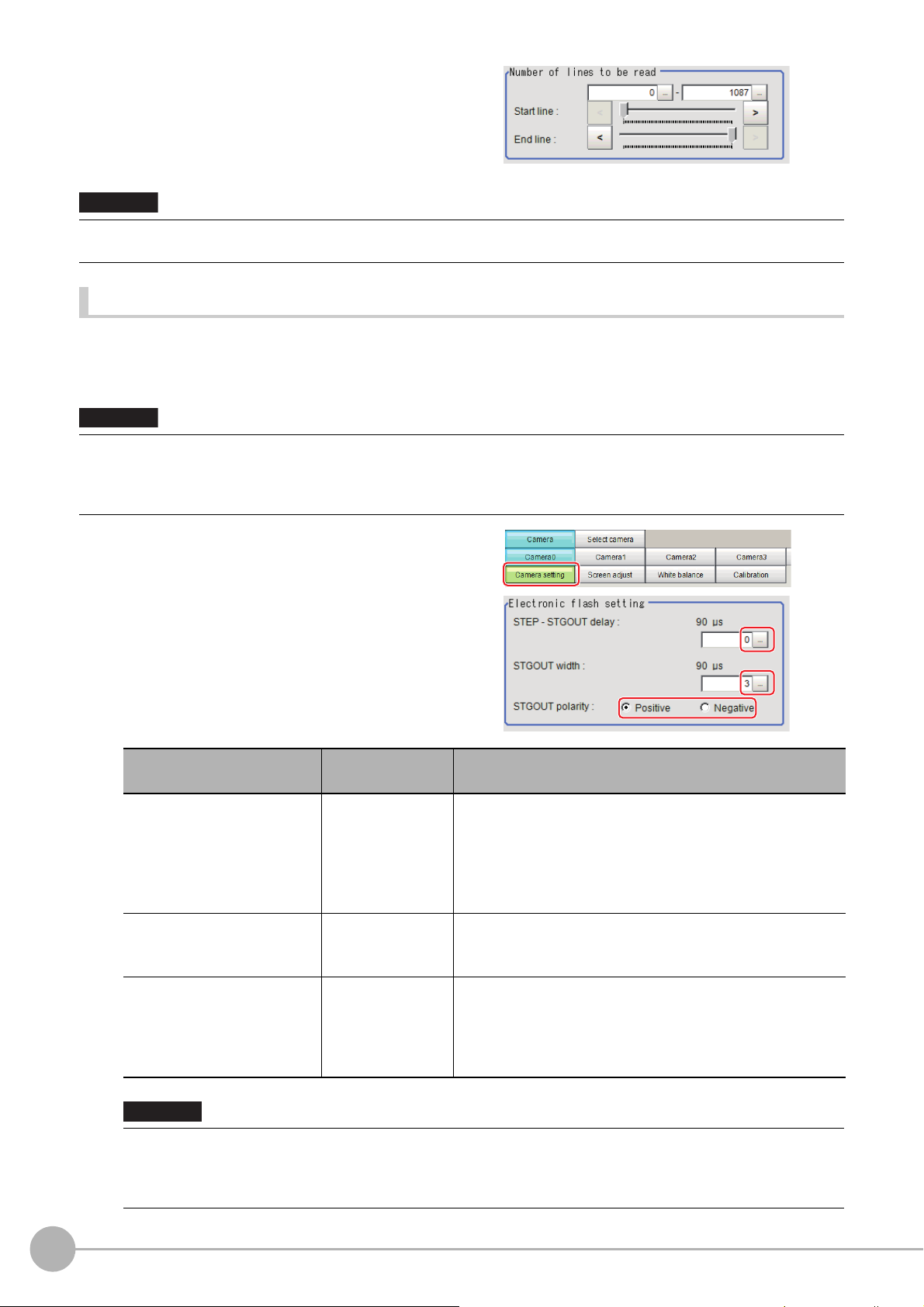
2 Set the start/end line in the "Number of
Important
Important
lines to be read" area.
• When the built-in lighting of an FZ-SQ is used, it may not be possible to shorten the processing time due to
restrictions on the light emission time.
Electronic Flash Setting
This function is set when an electronic flash is used. This sets the output conditions for the signal for
synchronizing the measurement and the electronic flash timing. It is possible to assign multiple electronic flashes
to a camera and control their flashing.
• The setting here applies when "STGOUT" is selected for the output sign
signal settings] page of the camera accessed by selecting [External Tools] - [System].
If "SHTOUT" is selected, the signal is controlle
Reference: Setting the SHTOUT Signal: [Output Signal Settings] in the Vision System FH/FZ5 Series User’s Manual (Z365).
d by each valu
e of SHTOUT set for each line.
al under [Common settings] on the [Output
1 In the Item Tab area, click [Camera
setting].
2 In the "Electronic flash setting" area,
specify each item.
Item
STEP - STGOUT delay
Setting value
[Factory default]
[0] to 511
(1 count 30μs)
Description
Set the waiting time from the time the STEP signal is input until
the
electronic flash trigger output signal comes ON.
Delay Time = Count × 30μs + 90μs
The displayed time is for the positive polarity.
Add 35μs to the
The delay time can be set in a range of ±10μs from the setting value.
displayed time if the polarity is negative.
52
STGOUT width
STGOUT polarity
Important
• Do not perform next camera image input processing before STGOUT sig
may not be output.
Perform camera image input processing after STGOUT signal output completion, or set the STEP-camera delay,
STEPSTGOUT delay and STGOUT pulse width so that the electronic flash operates synchronizing with the exposure time.
Camera Image Input FH
0 to 43689
[3]
(1 count is 30μs)
• [Positive]
• Negative
Set the output time for the electronic flash trigger signal.
On the FH series Sensor Controller, if 0 is set, the electronic
fla
sh will not flash.
Select the pulse polarity of the electronic flash trigger.
Positive polarity: Flashes synchronized with the timing of the
e
lectronic flash tri
Negative: Flashes when the strobe
changes from ON to OFF.
FH/FZ5 Processing Item Function Reference Manual
gger output signal changing from OFF to ON.
er output signal
trigg
nal output is completed. STGOUT signal
Page 55

Assigning Multiple Electronic Flashes to a Camera
Important
It is possible to assign multiple electronic flashes (STGOUT signals) to a camera and select one to use when an
image is taken for measurement. This function uses STGOUT signals with which cameras are not connected.
This function can be used only with FH series Sensor Controller.
Follow the setting procedure below.
• The STGOUT signals that can be output are as follows.
: FH-1000 and FH-3000 series: SGTOUT 0 to 7
: FH-L series: STGOUT 0 to 3
• STGOUT0 to STGOUT7 is tied to the camera connector number of the se
you use CameraLink Medium Configuration or the Multi-line random-trigger mode, confirm the camera connector
number that corresponds to the camera number of Sensor Controller.
nsor con
troller, not the camera number. When
1 Click [Tool] - [System settings] - [Camera] - [Output signal setting].
Reference: Setting the SHTOUT Signal: [Output Signal Settings] in the Vision System FH/FZ5 Series
User's Manual (Cat. No. Z365).
2 Select [STGOUT] for [Output Signal] in "Common setting" area.
3 Place a check to [Output even if camera is not connected] in "STGOUT setting" area.
With this setting, STGOUT signals (STGOUT0 to STGOUT7) which are not connected with cameras can
be used. Configure the STGOUT Width of the STGOUT of corresponding Camera Image Input FH
Processing Item.
Reference: Electronic Flash Setting of the Vision System FH/FZ5 Series Processing Item Function
ence Manual (Cat No. Z341).
fer
Re
1
Input image
Example:
Camera 0 uses STGOUT0 and STGOUT1 and Camera 2 uses STGOUT2.
4 To use STGOUT0 and STGOUT1 for Camera 0, Camera 1 is not connected with a camera.
5 In the [Electronic flash setting] area in the Camera 0 tab of Camera Image Input FH
processing item, enter the settings for SGTOUT 0.
6 In the [Electronic flash setting] area in the Camera 1 tab of Camera Image Input FH
processing item, enter the settings for SGTOUT 1.
7 In the [Electronic flash setting] area in the Camera 2 tab of Camera Image Input FH
processing item, enter the settings for SGTOUT 2.
8 In the [Electronic flash setting] area in the Camera 3 to 7 tab of Camera Image Input FH
processing item, set 0 to the STGOUT width.
Camera Image Input FHFH/FZ5 Processing Item Function Reference Manual
53
Page 56

If an electronic flash is not used or it does not flash, enter 0 to the [STGOUT Width].
Note
Important
Screen Adjustment Settings (Camera Image Input FH)
Set the lighting and lens conditions for each camera.
• Reference: Lighting Control (p.54)
• Reference: Line Bright (p.63)
Lighting Control
When an Electronic flash controller or Camera-mount Lighting Controller is connected, the light volume of the lighting
can be adjusted from the sensor controller. Brightness can be adjusted automatically or one of the preset patterns can
be selected.
1 In the Item Tab area, click [Screen
adjust].
2 In the "Lighting control" area, specify the brightness.
Displayed contents differ depending on the connected camera, Electronic flash controller or Cmara-mount
Lighting Controller.
Intelligent Compact Digital Camera FZ-SQ is connected:
Item
Pattern select Pattern 0 to 1
Adjustment
Setting value
[Factory default]
0: Unlit
1: Lit
Description
Select from a preset lighting pattern.
Pattern 0: Lit
Pattern 1: Unlit
Adjust the light volume of each part.
54
• When the lighting of FZ-SQ is used, there are following restrictions.
: The measurement can be longer than the
: There are restrictions in the opera
Reference: Multi-trigger Imaging (p.87)
Camera Image Input FH
measurement with the lighting OFF.
tion of Multi-trigger Imaging.
FH/FZ5 Processing Item Function Reference Manual
Page 57

Electronic flash controller FZ-LTA100 is connected:
1
Input image
Electronic flash controller FZ-LTA200 is co
0 + 1CH are used: 0CH is used: 1CH is used:
Item
Pattern select Pattern 0 to 16 Select from a preset lighting pattern.
CH
Adjustment
Setting value
[Factory default]
• [Checked]
• Unchecked
0 to 255
[128]
Place a check here to enable the channel currently selected in the part list.
When 1 channels are used, the light volume can be adjusted to one of 256
l
vels. When 2 channels are used, the light volume can be adjusted to one of
e
128 levels. 0 indicates the lighting is OFF. The larger the number, the higher
the brightness.
nnected:
Description
Camera Image Input FHFH/FZ5 Processing Item Function Reference Manual
55
Page 58
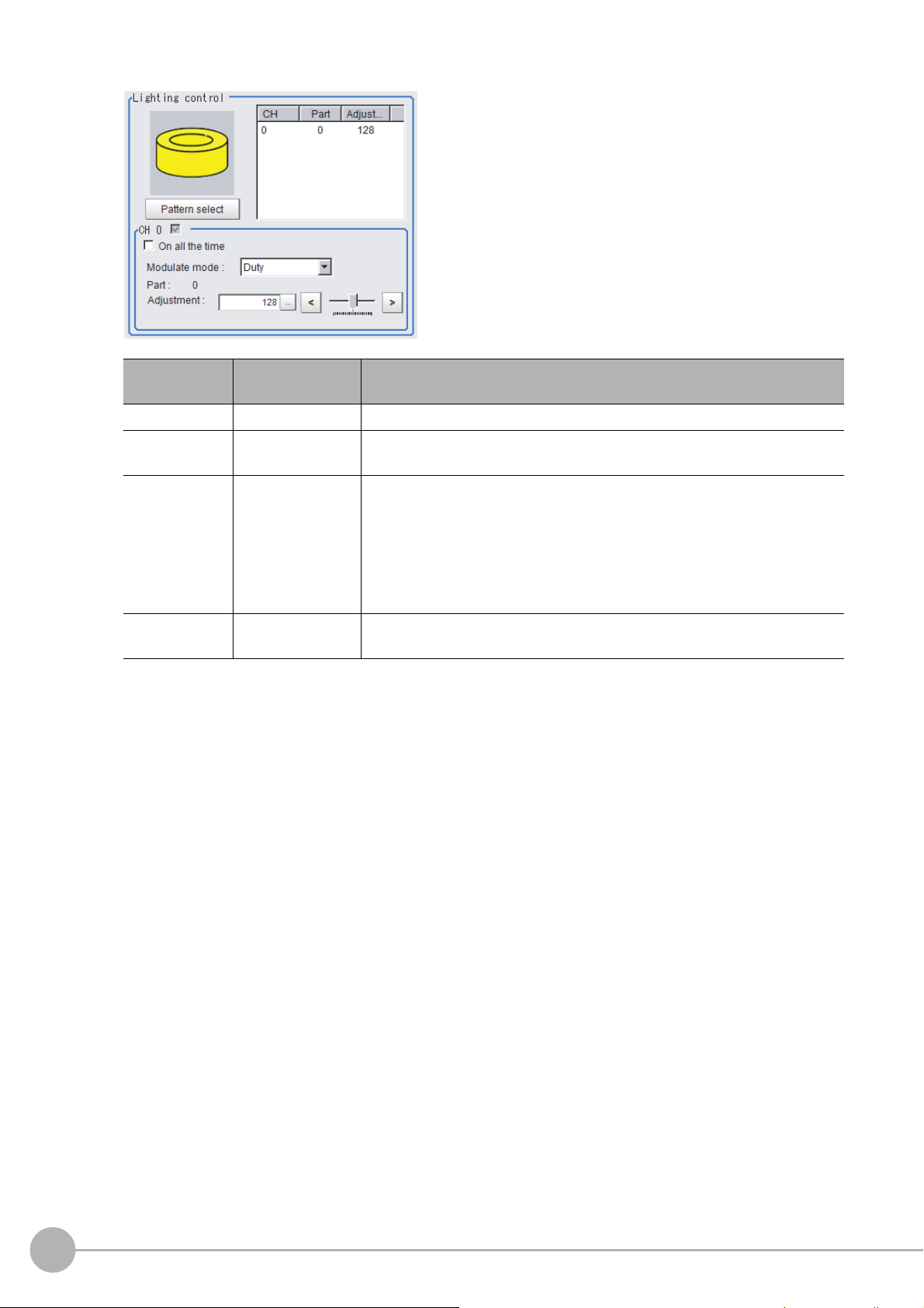
Camera-mount Lighting Controller FLV-TCC1 is connected:
Item
Pattern select
On all the time
Modulate mode
Part
Setting value
[Factory default]
---
•Checked
• [Unchecked]
•[Duty]
• Voltage / Current
0 to 255
[128]
Description
Select from preset lighting patterns.
Place a check here to keep the light turned ON
exposure time.
Select the lighting a
•Duty
The brightness of the light is adjusted with 255
(PWM frequency: 100 kHz).
• Voltage / Current
The brightness of the light is adjusted with 255 voltage / current levels.
Select voltage lighting adjustment if you will use a high-speed shutter speed.
Set the brightness for the selected parts.
justment method.
d
of the time regardless of the
all
levels of the pulse width
56
Camera Image Input FH
FH/FZ5 Processing Item Function Reference Manual
Page 59

Camera-mount Lighting Controller FLV-TCC4 is connected:
1
Input image
Item
Pattern select
On all the time
Modulate mode
Part
Setting value
[Factory default]
---
•Checked
• [Unchecked]
•[Duty]
• Voltage / Current
0 to 255
[128]
Description
Select from preset lighting patterns.
Place a check here to keep the light turned ON
exposure time.
Select the lighting a
•Duty
The brightness of the light is adjusted with 255
(PWM frequency: 100 kHz).
• Voltage / Current
The brightness of the light is adjusted with 255 voltage / current levels.
Select voltage lighting adjustment if you will use a high-speed shutter speed.
Set the brightness for the selected parts.
justment method.
d
of the time regardless of the
all
levels of the pulse width
Camera Image Input FHFH/FZ5 Processing Item Function Reference Manual
57
Page 60
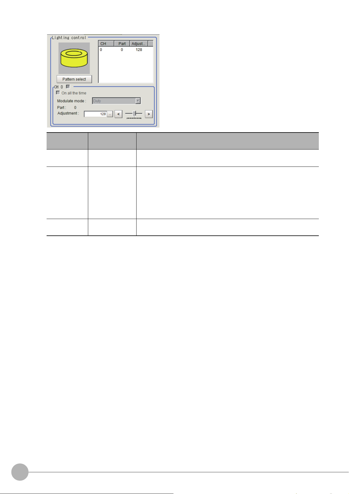
Camera-mount Lighting Controller FLV-TCC1EP is connected:
Item
On all the time
Modulate mode
Part
Setting value
[Factory default]
•Checked
• [Unchecked]
•[Duty]
• Voltage / Current
0 to 255
[128]
Description
Place a check here to keep the light turned ON all
exposure time.
Select the lighting a
•Duty
The brightness of the light is adjusted with 255
(PWM frequency: 100kHz).
• Voltage / Current
The brightness of the light is adjusted with 255 voltage / current levels.
Select voltage / current adjustment if you will use a high-speed shutter speed.
Set the brightness for the selected parts.
justment method.
d
of the time regardless of the
levels of the pulse width
58
Camera Image Input FH
FH/FZ5 Processing Item Function Reference Manual
Page 61

Camera-mount Lighting Controller FLV-TCC3HB is connected:
1
Input image
Item
On all the time
Modulate mode
Part
Setting value
[Factory default]
•Checked
• [Unchecked]
•[Duty]
• Voltage / Current
0 to 255
[128]
Description
Place a check here to keep the light turned ON all of the time regardless of the
exposure time.
Select the lighting a
0ch connected:
•Duty
The brightness of the light is adjusted with 255
(PWM frequency: 100kHz).
• Voltage / Current
The brightness of the light is adjusted with 255
0ch is the channel for the spot lighting.
1ch / 2ch connected:
•Duty
The brightness of the light is adjusted with 255
(PWM frequency: 100kHz).
• Voltage / Current
The brightness of the light is adjusted with 255 voltage / current levels.
Select voltage / current adjustment if you will use a high-speed shutter speed.
Set the brightness for the selected parts.
justment method.
d
levels of the pulse width
voltage / current levels.
levels of the pulse width
Camera Image Input FHFH/FZ5 Processing Item Function Reference Manual
59
Page 62
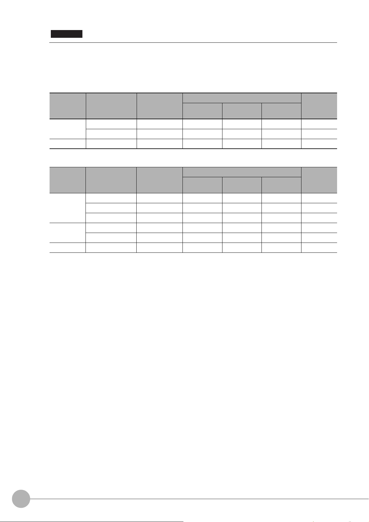
Important
Total powe r
consumption
Power consumption
per channel
Connectability
Lighting mode
*1
READY OFF
time delay
*2
Always-on
lighting mode
Simultaneous
lighting mode
Single lighting
mode
Greater than
7.5 W
Greater than 7.5 W Not connectable --- --- --- ---
7.5 W or less Connectable NA NA OK None
7.5 W or less Less than 7.5 W Connectable OK OK OK None
Total powe r
consumption
Power consumption
per channel
Connectability
Lighting mode
*1
READY OFF
time delay
*2
Always-on
lighting mode
Simultaneous
lighting mode
Single lighting
mode
Greater than
15 W
Greater than 15 W Not connectable --- --- --- ---
15 W or less Connectable NA NA OK Yes
7.5 W or less Connectable NA NA OK None
15 W or less
Less than 15 W Connectable NA OK OK Yes
7.5 W or less Connectable NA OK OK Yes
7.5 W or less Less than 7.5 W Connectable OK OK OK None
• There is no restriction on power consumption nor on lighting mode when using lightings with lighting controller
FLV-TCC1EP. Restrictions on power consumption and lighting mode differ depending on the product series. See
the following table for details.
1. FLV-TCC4/-TCC1
• Without external power supply
• With external power supply
60
Camera Image Input FH
FH/FZ5 Processing Item Function Reference Manual
Page 63

2. FLV-TCC3HB
Total powe r
consumption
Power consumption
per channel
Connectability
Lighting mode
*1
READY OFF
time delay
*2
Always-on
lighting mode
Simultaneous
lighting mode
Single lighting
mode
Greater than
7.5 W
Greater than 7.5 W Not connectable --- --- --- ---
7.5 W or less Connectable NA NA OK None
7.5 W or less Less than 7.5 W Connectable OK OK OK None
Total powe r
consumption
Power consumption
per channel
Connectability
Lighting mode
*1
READY OFF
time delay
*2
Always-on
lighting mode
Simultaneous
lighting mode
Single lighting
mode
Greater than
5.5 W
Greater than 7.5 W Not connectable --- --- --- ---
7.5 W or less Connectable NA NA OK None
5.5 W or less Less than 5.5 W Connectable OK OK OK None
Total powe r
consumption
Power consumption
per channel
Connectability
Lighting mode
*1
READY OFF
time delay
*2
Always-on
lighting mode
Simultaneous
lighting mode
Single lighting
mode
Greater than
15 W
Greater than 15 W Not connectable --- --- --- ---
15 W or less Connectable NA NA OK Yes
7.5 W or less Connectable NA NA OK None
15 W or less
Less than 15 W Connectable NA OK OK Yes
7.5 W or less Connectable NA OK OK Yes
7.5 W or less Less than 7.5 W Connectable OK OK OK None
Total powe r
consumption
Power consumption
per channel
Connectability
Lighting mode
*1
READY OFF
time delay
*2
Always-on
lighting mode
Simultaneous
lighting mode
Single lighting
mode
Greater than
14 W
Greater than 15 W Not connectable --- --- --- ---
15 W or less Connectable NA NA OK Yes
7.5 W or less Connectable NA NA OK None
14 W or less
Less than 14 W Connectable NA OK OK Yes
7.5 W or less Connectable NA OK OK Yes
5.5 W or less Less than 5.5 W Connectable OK OK OK None
• Without external power supply
0ch (spot lighting) not connected
0ch (spot lighting) connected
1
Input image
• With external power supply
0ch (spot lighting) not connected
0ch (spot lighting) connected
Camera Image Input FHFH/FZ5 Processing Item Function Reference Manual
61
Page 64

*1: Lighting modes
Always-on
lighting mode
In this mode, the lights are always turned ON for a specific pulse cycle. The always-on lighting mode is
used if you place a check in “On all the time” in the “Lighting control” area.
Simultaneous
lighting mode
In this mode, all of the connected lights are turned ON in synchronization with the trigger. Set the
“Adjustment” set values in the “Lighting control” area for each light to any value other than 0 for all of
the parts.
Single
lighting mode
In this mode, only one of the connected lights is turned ON in synchronization with the trigger. Set the
“Adjustment” set value in the “Lighting control” area to any value other than 0 for the part for only one
channel. The lights will not turn ON if you set two or more channels to an adjustment other than 0.
*2: Turning OFF the READY signal is delayed in comparison with not connecting a camera with lighting controller by
approximat
ely the exposure time.
Example: Connection example for connecting an external power supply and the lighting modes
• If four lights with a power consumption of 1 W each a
re connected to a camera with lighting controller,
always-on lighting, simultaneous lighting, and single lighting are all possible.
• If four lights with power consumptions of 2 W, 3 W, 4 W
and 5 W are connected to a camera with lighting
,
controller, simultaneous lighting and single lighting are possible.
• If four lights with power consumptions of 12 W, 1 W, 2 W
and 1 W are connected to a camera with lighting
,
controller, only single lighting is possible.
62
Camera Image Input FH
FH/FZ5 Processing Item Function Reference Manual
Page 65

Line Bright
R, G, B graph lines
Max. density value (red)
Indicates the max. density value.
Coordinate axis (yellow)
This line is moved to the location in which
density is to be checked.
The graph showing the gray distribution for 1 line in the image is called the "Line bright". You can display the line
brights for R, G and B for any horizontal or vertical line.
1
1 In the Item Tab area, click [Screen
adjust].
2 Place a check at "Display line bright".
3 Move the line to the position whose
density distribution you want to see.
Input image
Camera Image Input FHFH/FZ5 Processing Item Function Reference Manual
63
Page 66

White Balance (Camera Image Input FH)
Note
Note
Set the white balance to make white objects look white by calibrating the color of images loaded from cameras.
By adjusting the white balance, the appropriate white color can
Appropriate values can also be set automatically.
• Perform the white balance setting only when a color camera is used.
• In the following cases, make sure to set white balance.
• When a new system is installed
• When a camera or lighting has been changed
Since measurement results may vary with changes of the white balan
has changed.
be reproduced under any lighting conditions
c
e setting, be sure to verify the operation after it
1 In the Item Tab area, click [White
balance].
2 Shoot a white piece of paper or cloth.
3 Click [Auto].
• When the "Too bright" or "Too dark" message is displayed, adjust the iris, shutter speed, gain and/or lighting
conditions until "Automatic adjustment is possible" is displayed.
64
Camera Image Input FH
FH/FZ5 Processing Item Function Reference Manual
Page 67

4 Set the "R", "G" and "B" values as necessary.
Item
White balance setting
•R
•G
•B
Setting value
[Factory default]
• R, G, and B:
0.001 to 7.999
(FZ-SQ:0.001 to 3.000)
•FZ-SC
[R=1.183]
[G=1.000]
[B=1.323]
•FZ-SC2M
[R=1.394]
[G=1.000]
[B=1.222]
•FZ-SHC
[R=1.375]
[G=1.000]
[B=1.452]
• FZ-SFC and FZ-SPC
[R=1.145]
[G=1.000]
[B=1.889]
•FZ-SC5M2
[R=1.351]
[G=1.000]
[B=2.314]
•FZ-SQ
[R=1.000]
[G=1.040]
[B=1.800]
•FH-SC
[R=1.000]
[G=1.000]
[B=1.000]
Description
Set the white balance.
Whiteness increases when the
val
increased.
"R", "G", and "B" is
ue of
1
Input image
Camera Image Input FHFH/FZ5 Processing Item Function Reference Manual
65
Page 68

Calibration (Camera Image Input FH)
Note
X : Y = 1 :
X : Y = 5 : 3
Calibration
Note
By setting the calibration, the measurement result can be converted and output as actual dimensions. The
calibration method is selected here.
There are three calibration methods, point, sampling, and parameter.
• Reference: Specifying Points and Setting (Point Specification) (p.66)
• Reference: Setting Calibration through Sampling Measurement (Samp
ling) (p.67)
• Reference: Inputting and Setting Values (Value Setting) (p.69)
• Reference: View Calibration Parameters (p.70)
• In order to output measurement values in actual dimensions, select [Calibration] to "ON" in [Output parameter] for each
processing unit. If [Calibration] is "OFF" (factory default), measurement results are output as camera image coordinate
values.
Specifying Points and Setting (Point Specification)
This is a method for performing calibration by selecting arbitrary points (in pixels).
Calibration parameters are calculated automatically when actual
Up to 3 points can be selected.
• When magnification is the same in
the X and Y directions
Select only 2 points.
X : Y = 1 : 1
• When magnification is not the same in the X and
Y directions
Select 3 points.
coordinates of selected locations are entered.
Calibration
• When 2 points are selected, the coordinate system is set to the left-hand system (forward in the clockwise direction).
Select 3 points to perform calibration including the coordinate system.
X : Y = 1 :
1 In the Item Tab area, click [Calibration].
2 In the "Calibration setting" area, select
"Specify point".
3 Click the first point on the screen.
66
Camera Image Input FH
FH/FZ5 Processing Item Function Reference Manual
Page 69

4 Set the actual coordinates for the
specified point.
The actual coordinate input window is
displayed.
Actual coordinate Setting value [Factory default]
1
Input image
Point coordinate X, Y
Actual coordinate X, Y
0 to 9999.9999
[Point you clicked in the window]
-99999.9999 to 99999.9999
[0]
5 Set the 2nd and 3rd points in the same way.
6 Click [Generate calibration parameters].
The calibration parameters will be generated.
Setting Calibration through Sampling Measurement (Sampling)
This is a method for setting calibration based on measurement results.
Calibration parameters are calculated automatically wh
coordinates for that position set.
en a registered model is searched and the actual
1 In the Item Tab area, click [Calibration].
2 In the "Calibration setting" area, select
"Sampling".
3 In the "Sampling" area, click [Register
model].
4 Use the Drawing tools to register the
model.
5 Set a search region as necessary.
The default value setting is for the entire
screen.
Camera Image Input FHFH/FZ5 Processing Item Function Reference Manual
67
Page 70

6 Click [Sampling measurement].
Measurement is performed.
The search result (cross-shaped cu
displayed in the Image Display area, and the
Sampling Coordinate window is displayed.
rsor) is
7 In the Sampling Coordinate window, set
the X and Y values.
8 Click [OK].
Point coordinates and actual coordinates are
registered in the "Sampling" area.
9 Move the object to be measured and repeat the Steps 3 to 8.
10 Click [Generate calibration parameters].
The calibration parameters will be generated.
68
Camera Image Input FH
FH/FZ5 Processing Item Function Reference Manual
Page 71

Inputting and Setting Values (Value Setting)
Lefthand
Righthand
X
Y
0
0
Forward
X
Y
Forward
Upperleft
Lowerleft
Center
Set calibration data directly with numerical values.
1 In the Item Tab area, click [Calibration].
2 In the "Calibration setting" area, select
"Parameter".
3 In the "Parameter" area, specify values
for the "Coordinate", "Origin" and
"Magnification".
Item
Setting value
[Factory default]
1
Input image
Description
Lefthand: Clockwise is forward when setting the
coordi
nates.
Righthand: Counter-clockwise is forward when
setti
Coordinate
Origin
Magnification 0.00001 to 9.99999 Specify the ratio of 1 pixel to the actual dimensions.
• [Lefthand]
• Righthand
•[Upperleft]
•Lowerleft
•Center
e coordinates.
ng th
Set where the origin of the actual
co
ordin
ates will be.
4 Click [Generate calibration parameters].
The calibration parameters will be generated.
Camera Image Input FHFH/FZ5 Processing Item Function Reference Manual
69
Page 72

View Calibration Parameters
View the set calibration data.
1 In the Item Tab area, click [Calibration].
2 In the "Calibration parameter" area,
confirm the calibration data.
Item Setting value Description
A Calculation value
B Ca
C Calculation value
D Calculation value
E Calculation value
F Calculation value
Field of view Calculation value This is an actual dimension in the X direction.
lculation value
These are calibration conversion values. Camera coordi
to actual coordinates based on these values. The conversion formulas for
actual coordinates are as follows:
• (X, Y): Measurement point (camera coordi
• (X', Y'): Conversion point (actual coordinates)
X'=A ×
X + B × Y
Y'=D × X + E × Y + F
+ C
nates are converted
nates), Unit: pix
70
Camera Image Input FH
FH/FZ5 Processing Item Function Reference Manual
Page 73

Camera Image Input HDR
Important
You can acquire a wide dynamic range image by combining images photographed consecutively at different
shutter speeds.
st,
With objects that generate halation, images with low-contra
this processing item is an effective substitute for camera image input.
Used in the Following Case
• To acquire stable images of objects for which halation occurs easily
Used to obtain images with a wide dynamic range in which dark areas are made brighter (text areas) and
bright areas are made darker (connector areas).
and environments with fluctuation in the lighting,
1
Input image
Before processing
After processing
• To measure images with low-contrast stably
Use high-contrast mode.
• [Camera Image Input] is preset for Unit 0. Do not set any processing item other than camera image input (camera image
input HDR, camera image input HDR Lite, camera image input FH) for Unit 0.
• Immediately after starting up the FH/FZ5 Sensor Controller an
image. No input image is processed as the same color image as in the factory default state.
• If you open the Properties Dialog Box before inputting an image, cli
the OK button in the dialog box will change the setting to the same color camera setting as the factory default setting.
(Reference: "FAQ For Measurement The measurement NG (image
monochrome camera" in the "Vision System FH/FZ5 Series User's Manual (Z365)")
d immed
iately after changing scenes, there will be no input
k the Cancel button to close the dialog box. Pressing
c
mismatch) error will result when connecting a
Camera Image Input HDRFH/FZ5 Processing Item Function Reference Manual
71
Page 74
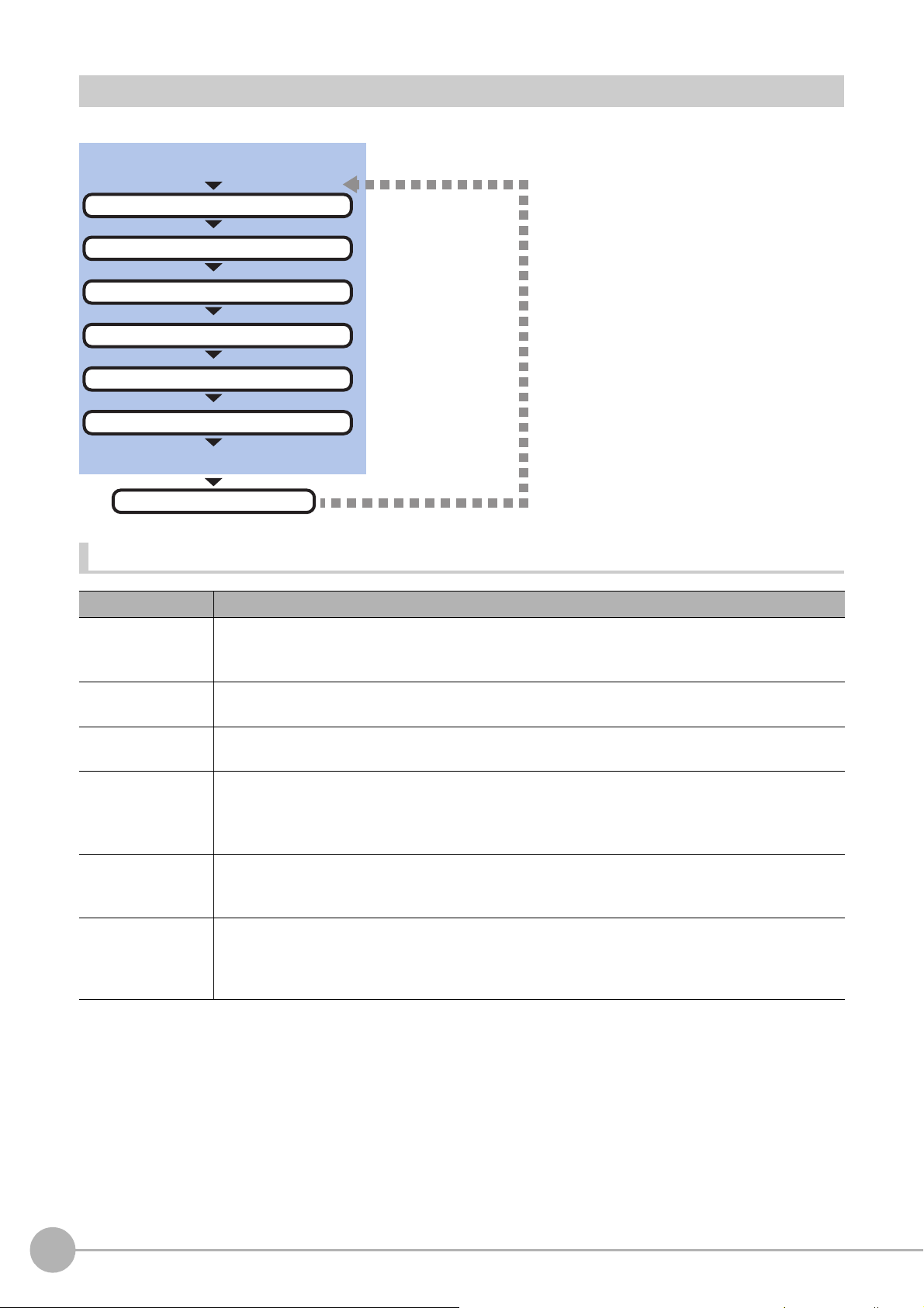
Settings Flow (Camera Image Input HDR)
Be sure to perform settings
Start
Settings complete
Results confirmation/adjustment
▲
Camera Settings (Camera Image Input HDR)
▲
HDR Settings (Camera Image Input HDR)
▲
Bright Adjust Setting (Camera Image Input HDR)
▲
Screen Adjustment Settings (Camera Image Input)
▲
White Balance (Camera Image Input)
▲
Calibration (Camera Image Input)
Test measurement
To set camera image input HDR, follow the steps below.
Camera Image Input HDR Item List
Item name Description
Specify the camera settings such a
Camera setting
HDR setting
Bright adjust
Screen adjust
White balance
Calibration
The setting method is the same as for [Camera Image Input]. Please check it.
Reference: Camera Settings (Camera Image Input HDR) (p.73)
Carry out the image combination and photography settings.
Reference: HDR Settings (Camera Image Input HDR) (p.76)
Specify the brightness follo
Reference: Bright Adjust Setting (Camera Image In
Adjust the lighting and the lens.
The setting method is the same as for [Camera Image Inpu
be adjusted.
Reference: Screen Adjustment Settings (Camera Image Input) (p.30)
When using a color camera, adjust the white balance.
The setting method is the same as for [Camera Image Input]. Please check it.
Reference: White Balance (Camera Image Input) (p.38)
Set when measurements (camera coordinate measurement va
dimensions. Select the calibration setting method and generate the calibration parameters.
The setting method is the same as for [Camera Image Input]. Please check it.
Reference: Calibration (Camera Image Input) (p.39)
s the electronic flash.
w-up adjustment setting.
put HDR) (p.78)
t]. Please check it. However, the iris cannot
lue
s) are to be output using actual
72
Camera Image Input HDR
FH/FZ5 Processing Item Function Reference Manual
Page 75

Camera Settings (Camera Image Input HDR)
Set the following photographing conditions.
• Reference: Selection Setting (p.73)
• Reference: Camera Settings (p.74)
• Reference: Number of lines to be read (p.29)
• Reference: Electronic Flash Setting (p.75)
Selection Setting
When multiple cameras are connected, select the camera to use for measurement.
1 In the Item Tab area, click [Camera setting].
2 Click [Camera No.] [ ] and select the
camera number.
Setting item Setting value [Factory default] Description
Camera No.
Cam 0 to 7
[Cam 0]
Select the camera number.
1
Input image
Camera Image Input HDRFH/FZ5 Processing Item Function Reference Manual
73
Page 76
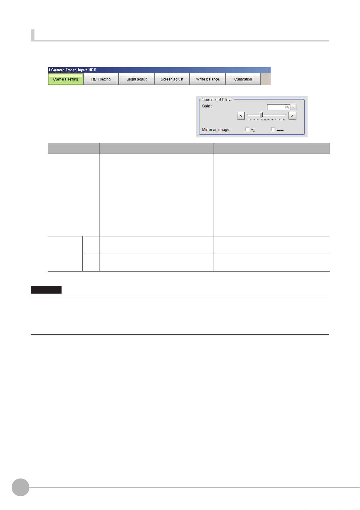
Camera Settings
Important
Specify the camera gain and reverse conversion.
1 In the Item Tab area, click [Camera setting].
2 In the "Camera settings" area, specify
the camera gain and reverse conversion
settings.
Setting item Setting value [Factory default] Description
• FZ-SC/S/SHC/SH
0 to 230 [85]
• FZ-SC2M/S2M/SC5M2/S5M2/SF/SP
0 to 230 [50]
Gain
• FH-SC02/SM02/SC04/SM04/SC12/SM12
0 to 255 [0]
• FH-SC05R/SM05R
0 to 63 [0]
Checked
•
↑↓
←→
•[Unchecked]
• Checked
•[Unchecked]
s sho
Mirror an
imag
e
With CMOS cameras, striped bands of noise can arise if the camera gain is se
imaging element specifications.
A number of pixel defects may also occur; however, such defect
If having problems with striped bands of noise or pixel defects affecting the measurement results, lower the camera gain
setting or use a CCD camera.
Set the camera gain when the shutter speed,
the len
s
aperture, and lighting conditions
cannot be used to brighten the image.
Usually, the factory default value can be used.
Place a check here when reversing the camera
imag
Place a check here when reversing the camera
imag
uld not cause problems with product defects or failure.
rtically.
e ve
e horizon
t too high, a characteristic inherent in the
tally.
74
Camera Image Input HDR
FH/FZ5 Processing Item Function Reference Manual
Page 77
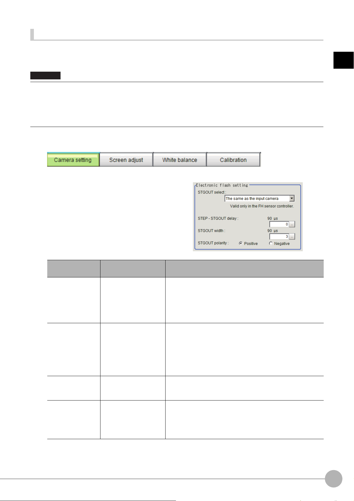
Electronic Flash Setting
Important
This function is set when an electronic flash is used. This sets the output conditions for the signal for
synchronizing the measurement and the electronic flash timing.
• The STGOUT signals that can be output are as follows.
: FH-1000 and FH-3000 series: SGTOUT 0 to 7
: FH-L series: STGOUT 0 to 3
• STGOUT0 to STGOUT7 is tied to The camera
When you use CameraLink Medium Configuration
number that corresponds to the camera number of sensor Controller.
connector number of the sensor controller, not the camera number.
or the Multi-line random-trigger mode, confirm the camera connector
1 In the Item Tab area, click [Camera setting].
2 In the Electronic flash setting area, set
the items of STGOUT signals.
1
Input image
Item
STGOUT select
STEP-STGOUT
de
lay
GOUT width
ST
STGOUT polarity
Setting value
[Factory default]
[The same as the input
a
mera]
c
Camera 0 to 7
to 511
[0]
(1 count is 30μs)
0 to 43689
[3]
(1count is 30μs)
• [Positive]
• Negative
Description
Select the STGOUT signal to use for Camera Image Input HDR
processing item.
The same as the input camera: STGOUT
camera is output.
Camera 0 to 7: STGOUT signal that is tied to the selected camera
is output.
Set the time to wait to turn ON the electronig flash trigger signal
af
r STEP signal is input.
te
Delay time = count number ×30μs+90μs
Delay time changes with the setting of STGOUT polarity.
The time displayed is for the polarity
35μs will be added to the displayed time.
Delay time is within the range ±10μs of
Set the time to output the electronic flash trigger signal.
For FH series controller, set 0 to disable flashing.
Set the pulse polarity of electronic flash trigger.
Positive: flashes synchronizing with the electronic flash trigger
outpu
t changing from OFF→ON.
Negative: flashes synchronizing with the electronic flashing trigger
outpu
ging from ON→OFF.
t chan
of Positive; for
set value.
that is
tied to the input
Negative,
Camera Image Input HDRFH/FZ5 Processing Item Function Reference Manual
75
Page 78

Do not perform next camera image input processing before STGOUT signal output is completed. STGOUT signal may not
Important
Note
be output.
Perform camera image input processing after STGOUT signal o
STEPSTGOUT delay and STGOUT pulse width so that the electronic flash operates synchronizing with the exposure time.
tput completion, or set the STEP-camera delay,
u
STGOUT signals are output at each imaging. Therefore,
depending on the STEP-STGOUT delay or STGOUT width settings.
If it duplicates with the next, the numbe
of times for imaging and electronic flashing can differ.
r
it can be duplicated with the next STGOUT signal output,
HDR Settings (Camera Image Input HDR)
Specify the image combination method etc.
1 In the Item Tab area, click [HDR setting].
2 In the "Mode select" area, specify the mode.
When you select the mode in the "Mode select" area and specify the measurement region on the image,
the parameters are set automatically. To finely adjust the parameters, refer to the next items.
Item
Mode
select
Set value
[Factory default]
[HDR mode]
High contrast mode
Description
In halation is likely generated image, select this mode if you want to stabilize the
brightness.
Generate images with stable brightness by sh
shutter speeds based on the set Bright range.
Select this mode if you want to generate image with good contrast.
Generate images with good contrast by shooti
shutter speeds based on the set Average and Width.
multiple images with different
ooting
ng multiple images with different
76
Camera Image Input HDR
FH/FZ5 Processing Item Function Reference Manual
Page 79
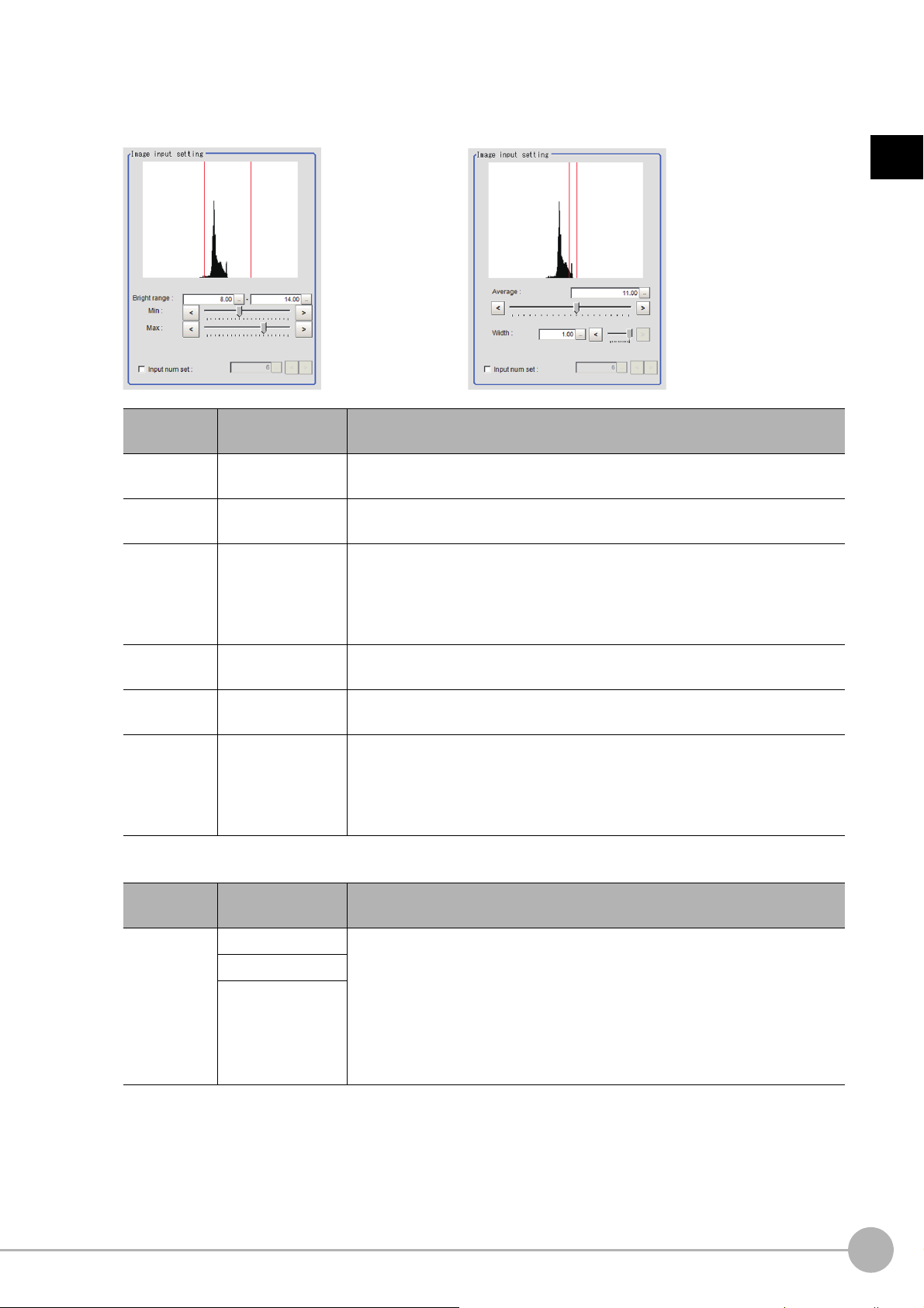
3 In the "Image input setting" area, set the items.
HDR High contrast mode
A brightness histogram is displayed as the graph.
1
Input image
Item
Min Bright
range
Max Bright
rang
e
Input num set
Average
Width
Input num set
Set value
[Factory default]
0 to 20
[8]
0 to 20
[14]
• [Unchecked]
• Checked
2 to 16
[6]
0.00 to 20.00
[11.00]
0.01 to 1.00
[1.00]
• [Unchecked]
• Checked
2 to 16
[6]
This item sets the minimum brightness for combining images.
This item sets the maximum brightness for combining images.
Place a check to set the number of shots manually.
Setting a high shot count provides ima
processing time is required.
Setting a low shot count shortens the processing time. However, the image is
more
Specify the average brightne
Specify the brightness range for images shot.
Place a check to set the number of shots manually.
Setting a high shot count provides ima
processing time is required.
Setting a low shot count shortens the processing time. However, the image is
more
ly affected by noise.
easi
ly affected by noise.
easi
ss for
4 In the "Output setting" area, set the combination method.
Description
ges with low no
images shot.
ges with low no
ise. However, more
ise. However, more
Item
Combine type
Set value
[Factory default]
[Normal] Select the combination method.
Color
Linear
Normal: Standard combination method This compensates the brightness so that
dark
sections on the combination image do not become all black.
Color: This is suitable for inspecting lab
compensates the saturation when there is little hue information in the combined
image.
Linear: This is suitable for fine matching and defect inspection. In order to output
the
actual brightness of the workpiece, no compensation is performed.
The current shot count and image combination time for the settings are displayed.
Description
ling and the Gravity and Area. This
e
Camera Image Input HDRFH/FZ5 Processing Item Function Reference Manual
77
Page 80
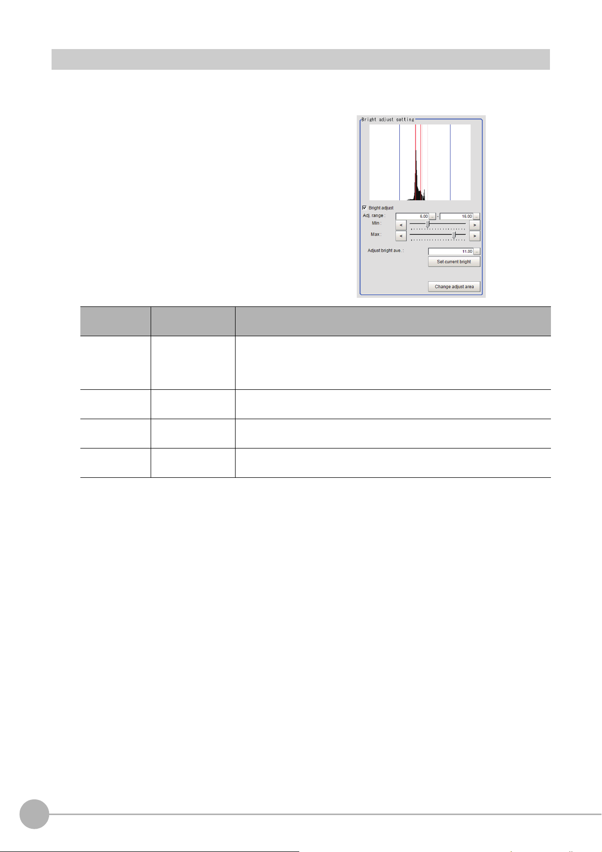
Bright Adjust Setting (Camera Image Input HDR)
This sets how far to track the brightness of the loaded images.
1 In the Item Tab area, click [Bright adjust].
2 Set each item in the "Bright adjust
setting" area.
Item
Bright adjust
Min Adj. range
Max Adj. range
Adjust bright
ave.
Set value
[Factory default]
• [Unchecked]
• Checked
0.00 to 20.00
[6.00]
0.00 to 20.00
[16.00]
0.00 to 20.00
[11.00]
Description
If a check is placed at "Bright adjust", the imag
automatically compensated. This makes it possible to obtain images with
stable brightness even if the lighting conditions fluctuate, for example due to
interfering light.
Specify the follow-up brightness minimum value.
Specify the follow-up brightness maximum value.
Specify the target for brightness follow-up. Clicking the [Set current bright]
button upd
ates thi
s value.
e is
output with its brightness
When a check is placed at the "Bright adjust", the Brightness Adjustment range is displayed with blue
lines in the "Histogram" area.
Change the "Adjust bright ave." and brightness adjust area.
78
Camera Image Input HDR
FH/FZ5 Processing Item Function Reference Manual
Page 81

Camera Image Input HDR Lite
Used to obtain images with a wide dynamic range in which dark areas are made brighter (text areas) and
bright areas are made darker (connector areas).
Before processing After processing
Important
Camera Image Input HDR Lite is for FZ-SQ.
You can acquire a wide dynamic range image by combining images ph
shutter speeds.
st,
With objects that generate halation, images with low-contra
and environments with fluctuation in the lighting,
this processing item is an effective substitute for camera image input.
Used in the Following Case
• To acquire stable images of objects for which halation occurs easily
otographed consecutively at different
1
Input image
• [Camera Image Input] is preset for Unit 0. Do not set any processing item other than camera image input (camera image
input HDR, camera image input HDR Lite and camera image input FH) for Unit 0.
• Immediately after starting up the FH/FZ5 Sensor Controller an
image. No input image is processed as the same color image as in the factory default state.
• If you open the Properties Dialog Box before inputting an image, cli
the OK button in the dialog box will change the setting to the same color camera setting as the factory default setting.
(Reference: "FAQ For Measurement The measurement NG (image
monochrome camera" in the "Vision System FH/FZ5 Series User's Manual (Z365)")
d immed
iately after changing scenes, there will be no input
k the Cancel button to close the dialog box. Pressing
c
mismatch) error will result when connecting a
Camera Image Input HDR LiteFH/FZ5 Processing Item Function Reference Manual
79
Page 82

Settings Flow (Camera Image Input HDR Lite)
Be sure to perform settings
Start
Settings complete
Results confirmation/adjustment
▲
Camera Settings (Camera Image Input HDR Lite)
▲
HDR Settings (Camera Image Input HDR Lite)
▲
Screen adjust (Camera Image Input HDR Lite)
▲
White Balance (Camera Image Input)
▲
Calibration (Camera Image Input)
Test measurement
To set Camera Image Input HDR Lite, follow the steps below.
Camera Image Input HDR Lite Item List
Item name Description
Camera settings
HDR setting
Screen adjust
Specify the camera settings such as the electronic flash.
Reference: Camera Settings (Camera Image Input HDR Lite) (p.81)
Specify the dynamic range and brightness setting. S
Reference: HDR settings (Camera Image Input HDR Lite) (p.81)
Adjust the image with or witho
Reference: Screen adjust (Camera Image Input HDR Lite) (p.82)
When using a color camera, adjust the white balance.
White balance
The setting method is the same as for [Camera Image Input]. Please check it.
Reference: White Balance (Camera Image Input) (p.38)
Set when measurements (camera coordinate measurement values) are to be output using actual
Calibration
dimensions. Select the calibration setting method and generate the calibration parameters.
The setting method is the same as for [Camera Image Input]. Please check it.
Reference: Calibration (Camera Image Input) (p.39)
peci
fy the HDR automatic setting as necessary.
ut the light adjustment or using display line bright.
80
Camera Image Input HDR Lite
FH/FZ5 Processing Item Function Reference Manual
Page 83

Camera Settings (Camera Image Input HDR Lite)
Set the following photographing conditions.
• Reference: Selection Setting (p.81)
• Reference: Number of lines to be read (p.29)
• Reference: Electronic Flash Setting (p.75)
Selection Setting
When multiple cameras are connected, select the camera to use for measurement.
1 In the Item Tab area, click [Camera setting].
2 Click [Camera No.] [ ] and select the
camera number.
Setting item
Camera No.
Setting value
[Factory default]
Cam 0 to 7
[Cam 0]
Description
Select the camera number.
1
Input image
HDR settings (Camera Image Input HDR Lite)
Specify the dynamic range and brightness settings.
1 In the Item Tab area, click [HDR Setting].
2 When automatic is clicked, the dynamic
range and the brightness will be
automatically set.
If automatic does not produce the desired
result, manually adjust the dynamic range and
brightness in the HDR settings.
Item
Dynamic Range [Level1] to Level4
Brightness 1 to 100
Set value
[Factory default]
Specify a dynamic range. The larger the value is, the broader the
dy
namic range to be combined will be.
Specify the brightness settings. The larger the value is in this setting, the
l
er the exposure time will be. When using a high-speed line, check to
ong
make sure that there is no image blur in an actual environment. The
degree of image blur can be lowered by decreasing the brightness even
when the movement speed of the object is fast.
Description
Camera Image Input HDR LiteFH/FZ5 Processing Item Function Reference Manual
81
Page 84

• Correlation between the level and the dynamic range
Important
The larger the value of the level is, the larger the dynamic range to
be combined will be, as illustrated below.
Level 1
Level 2
Level 3
Level 4
Dark
• For stable operations, we recommend setting the brightness within the range where the blue bar does not enter the red
region. Measurement values may be different if the recommended range is exceeded. Be sure to thoroughly check the
measurement result and set the brightness value.
Light
Screen adjust (Camera Image Input HDR Lite)
Specify the camera image input HDR Lite lighting and the line bright display settings. Specify whether or not to
use the lighting. The setting method for line bright is the same as for [Camera Image Input]. Please check it.
• Reference: Line Bright (p.37)
1 In the Item Tab area, click [Screen
adjust].
2 Set [Lighting control] as necessary.
82
Item
Lighting on
Camera Image Input HDR Lite
Set value
[Factory default]
• [Checked]
• Unchecked
Description
Clear the checkbox when no lighting is to be applied.
FH/FZ5 Processing Item Function Reference Manual
Page 85

Camera Switching
Camera
0
Camera
1
Camera
2
Camera
3
Select a
camera
Important
The Position Compensation for Unit 1 is being
cancelled, making it restore to its former state before
the Position Compensation was applied.
Used in the Following Case
• When switching to images on cameras other than that has been set to [Camera Image Input]
during scene processing
• When switching from a monochrome camera to color camera, reconfigure the settings in the following units.
• Camera switching cannot be used with camera image input HDR.
1
Input image
Camera Selection (Camera Switching)
1 Select the cameras used for
measurement.
2 Click [OK].
The settings are finalized.
Additional Explanation (Camera Switching)
When creating a scene, [Position Compensation] will be disabled if [Camera Switching] is positioned after a
[Position Compensation] unit, and this will restore the image of the measurement object to its former state before
the position compensation was applied.
Camera SwitchingFH/FZ5 Processing Item Function Reference Manual
83
Page 86
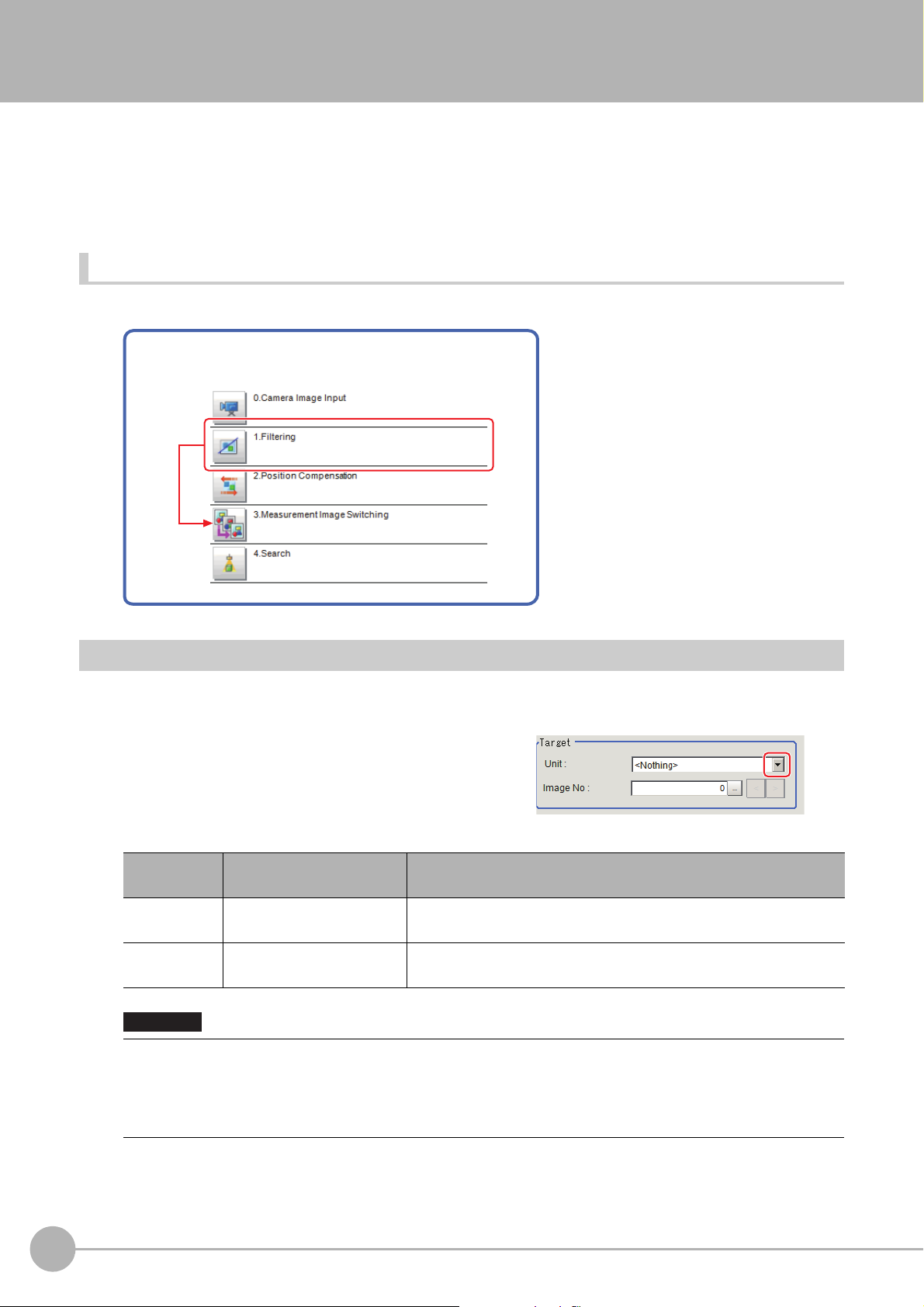
Measurement Image Switching
Example) Performing a search after returning to the image from
before position compensation was performed
This sets the output image for the camera image input processing items and specified image conversion related
processing items as the input image for the processing items set in the flow from this processing item onward.
o
This is primarily used to return converted images back t
selected as conversion targets for image conversion related processing items by placing before the image
conversion related processing items.
Used in the Following Case
• To return a converted image to its original
their originals and to increase the images that can be
Parameter Settings (Measurement Image Switching)
Specify the processing unit that outputs the images to configure.
Select one that is located in upper position than this processing unit in the flow.
1 Select the target unit in the "Target"
area.
Item
Unit
Image No.
0 to 9999 processing unit
[<Nothing>]
0 to 9999
[0]
Important
• If <Nothing> is left selected, the measuremen
other than <Nothing>.
• Selectable Camera Image Input or Compensate Image
Reference: "Macro Reference - List of Image Number
Functions Programming Manual (Z367)"
Set value
[Factory default]
Description
Unit that outputs images subject to reset. Select one
upper position than this processing unit in the flow.
No. of the image that the target unit holds.
t image
switching measurement result is NG. Be sure to select one
cessing items and their image No. are as follows.
pro
s" in the "Vision System FH/FZ5 Series Macro Customize
that is located in
84
Measurement Image Switching
FH/FZ5 Processing Item Function Reference Manual
Page 87

Processing items Image No. Image
Camera Image Input 0 Camera image
Camera Image Input FH 0 Camera image
Camera Image Input HDR 0 Camera image
Camera Image Input HDR Lite 0 Camera image
Position Compensation 0 Position compensated image
Filtering 0 Filtered image
Background Suppression 0 Background suppressed image
brightness Correct Filter 0 Brightness corrected image
Color Gray Filter 0 Color gray image
Extract Color Filter 0 Color extracted image
Anti Color Shading 0 Anti color shading image
Stripes Removal Filter II 0 Stripes removed image
Polar Transformation 0 Polar transformed image
Trapezoidal Correction 0 Trapezoidal corrected image
Machine Simulator 0 Axis shifted image
Image Subtraction 0 Subtraction image
0 Output image 0
1 Output image 1
Advanced filter
2 Output image 2
1
Input image
3 Output image 3
Panorama 0 Panorama image
2 Click [OK].
The settings are finalized.
Key Points for Test Measurement and Adjustment (Measurement Image Switching)
The image specified in the Sub-image number in image display setting is displayed in the image display area.
Sub image number Explanation of image to be displayed
0 Reset image
1 Measurement image
Measurement Image SwitchingFH/FZ5 Processing Item Function Reference Manual
85
Page 88

External Reference Tables (Measurement Image Switching)
No. Data name Set/Get Data range
0: No judgement (unmeasured)
1: Judgement result OK
-1: Judgement result NG
0 Judge Get only
-10: Error (image format mismatch)
-11: Error (unregistered model)
-12: Error (Insufficient memory)
-20: Error (Other error)
120 Target unit Set/Get
121 Image no. Set/Get
Unit that outputs images subject to reset
0 to 9999
Target image No, that the target unit holds
Image no. 0 to 9,999
86
Measurement Image Switching
FH/FZ5 Processing Item Function Reference Manual
Page 89

Multi-trigger Imaging
1st STEP
2
nd
STEP
3
rd
STEP
3. Search
9. Search
6. Search
1
st
STEP
2
nd
STEP
3
rd
STEP
Image transfer completed
Image transfer completed
Image transfer completed
2. Camera
image input FH
5. Camera
image input FH
8. Camera
image input FH
This function can be used only with FH series/FZ5-800 series/FZ5-1100 series/FZ5-1200 series. The Multitrigger Imaging processing item captures multiple images at user-defined timings and executes parallel
measurement for each image. If you append this processing item in the flow, Multi-trigger Imaging, Multi-trigger
Imaging Task, Camera Image Input FH and Multi-trigger Imaging End will be added as a group. Insert the Multitrigger Imaging to the top of the flow. The Multi-trigger Imaging, Multi-trigger Imaging Task, and Multi-trigger
Imaging End cannot be used alone. Please use them as a group.
1
Input image
Reference: Cha
nging the System Environment - Multi-trigger Ima
ging Function in the Vision System FH/FZ5
Series User's Manual (Cat. No. Z365).
Used in the Following Case
Systems which capture multiple images at user-defined timings and executes parallel measurement for each
image.
Example:
This function takes multiple images of a long and thin
workpiece
images for multiple times, it executes measurement for each image in parallel. After that, measurement
processing is performed based on the measurement results.
Move
at certain timings. While the system takes
STEP(0)
STEP(1)
STEP(2)
Multi-trigger ImagingFH/FZ5 Processing Item Function Reference Manual
87
Page 90
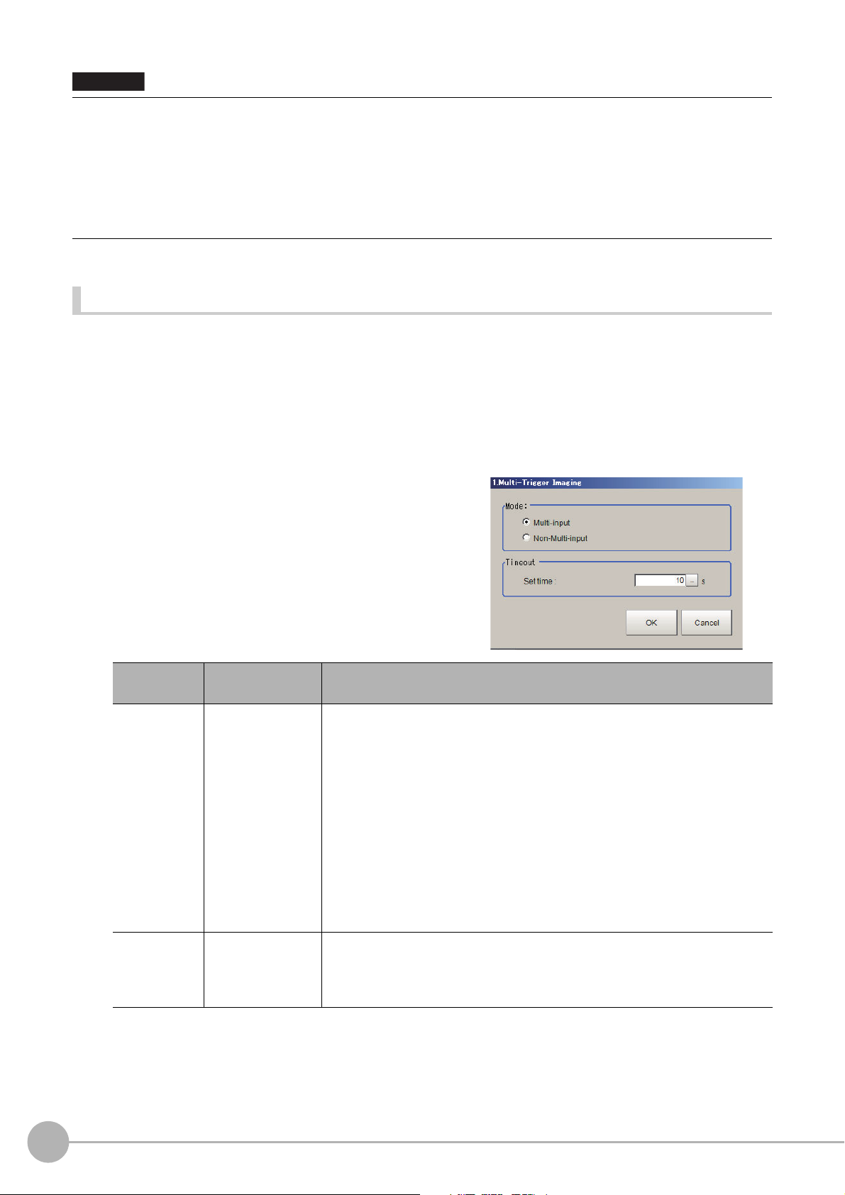
• Multi-trigger Imaging cannot be used when the Operation mode is [Double Speed Multi-input].
Important
• Set the Multi-trigger Imaging processing item to
• Always set only one Multi-trigger Imaging processing item in one flow.
• The signals that can be used as an image ca
Measurement executed by signals other than these signals or control command does not wait the STEP signal and flow
is executed automatically as the controller does in the previous system.
• If the Image mode of the Image Window Setting is set as [T
in the previous system.
the top (unit 0) of the flow.
pture tri
gger are STEP signal of parallel and Trigger signal of EtherCAT.
hrough], flow is executed automatically as the controller does
Mode and timeout (Multi-trigger Imaging)
Configure the Mode and Timeout of Multi-trigger Imaging processing item.
Reference: Multi-trigger Imaging Function in the Vision System FH/FZ5
Series User's Manual (Cat. No.Z365)
1 On the Main Window (Layout 0), select [Function] - [Edit flow].
2 Select a Multi-trigger Imaging processing item.
3 Click the [Set] button.
4 Configure the Mode and Timeout.
Item
Mode
Timeout
Set value
[Factory default]
• [Multi-input]
• Non-Multi-input
1 to 60s
[10]
Description
Set the processing mode of Multi-tri
• Multi-input mode:
Select this if Multi-input mode is use
The Camera setting for the Input image proces
trigger Imaging Task is applied to that for other Input image processing items
that are executed in Multi-trigger Imaging Tasks.
• Non-Multi-input:
Cameras operate according to their own settings.
The Camera setting for the Input image proce
Imaging Task is applied to each execution of Input image processing items.
Because Camera setting is executed at each execution of Input image
processing item, the time that READY signal stays OFF becomes longer by
several ms to several tens of ms compared with that in Multi-input mode.
Set the time for timeout of Multi-trigger Imaging Task block.
It is a wait time between a Multi-trigge
STEP signal is not input within the timeout time after the READY signal turns
ON, the Multi-trigger Imaging unit judgment will be NG.
gger Imaging Task.
in the Multi-trigger Imaging Task.
d
sing item of the first Multi-
sing item of the Multi-trigger
s
r
Imaging Task and the next one. When a
88
Multi-trigger Imaging
FH/FZ5 Processing Item Function Reference Manual
Page 91

• In the following cases, the system operates in Multi-input mode, regardless of the settings for Mode.
Important
: Camera Image Input HDR or Camera Image Input HDR Lite is used.
: Multiple Input image processing items are used in one Multi-trigger Imaging Task block.
: FZ-SQ□□
: Input image processing item is inserted outside of the range
End processing items.
• There are restrictions below when FZ-FQ□□□
: All Camera Image Input processing items operate with the settings
Imaging Task in the flow.
: The system operates in Multi-input
: When the light of FZ-FQ□□□□ camera is OFF
□□ camera is used with its light ON.
mode disabled. (It t
between Multi-trigger Imaging and Multi-trigger Imaging
camera is used with its light ON.
□
for the Camera Image Input of the first Multi-trigger
akes longer time to turn ON the READY signal).
, the camera operates in the same way as other camera does.
Key Points for Adjustment
Select the adjustment method referring to the following points.
When there is poor image capture results
Parameter to adjust Description
Input units between a Multi-Trigger
ted units are
t rela
Edit flow
Verify that there are no additional Camera Image
Imaging block and the first Multi-Trigger Imaging task.
If there is a Camera Image Input related unit in this position, image capture results will
no
correct.
t be
When using Multi-Trigger Imaging, ensure that Camera Image Inpu
contained inside a Multi-Trigger Imaging task.
1
Input image
The number of Multi-Trigger Imaging tasks do
signal inputs.
Verify that the number of Multi-T
inputs match and try image capture again.
igger Imaging tasks and the number of STEP signal
r
not match the number of STEP
es
Multi-trigger ImagingFH/FZ5 Processing Item Function Reference Manual
89
Page 92
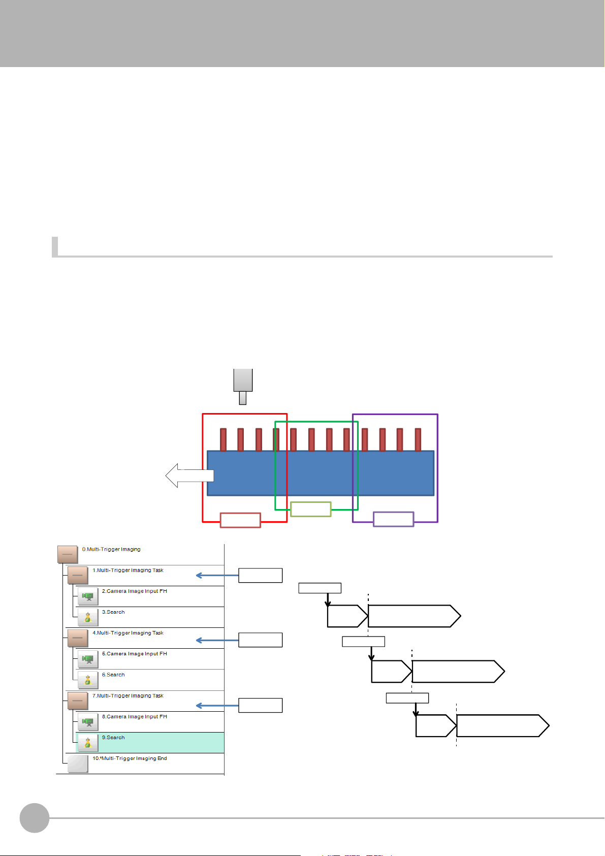
Multi-trigger Imaging Task
1st STEP
2
nd
STEP
3
rd
STEP
3. Search
9. Search
6. Search
1
st
STEP
2
nd
STEP
3
rd
STEP
Image transfer completed
Image transfer completed
Image transfer completed
2. Camera
image input FH
5. Camera
image input FH
8. Camera
image input FH
This function can be used only with FH series/FZ5-800 series/FZ5-1100 series/FZ5-1200 series. The Multitrigger Imaging processing item captures multiple images at user-defined timings and executes parallel
measurement for each image. If you append this processing item in the flow, Multi-trigger Imaging Task and
Camera Image Input FH will be added as a group. The Multi-trigger Imaging Task does not require setting. Insert
this processing item to the top of the processing which requires imaging for multiple times. The Multi-trigger
Imaging, Multi-trigger Imaging Task, and Multi-trigger Imaging End cannot be used alone. Please use them as a
group.
Reference: Cha
nging the System Environment - Multi-trigger imag
ing Function in the Vision System FH/FZ5
Series User's Manual (Cat. No. Z365).
Used in the Following Case
Systems which capture multiple images at user-defined timings and executes parallel measurement for each
image.
Example:
This function takes multiple images of a long and thin workpiece
images for multiple times, it executes measurement for each image in parallel. After that, measurement
processing is performed based on the measurement results.
Move
at certain timings. While the system takes
90
Multi-trigger Imaging Task
STEP(0)
STEP(1)
STEP(2)
FH/FZ5 Processing Item Function Reference Manual
Page 93

• The signals that can be used as STEP signals are STEP signal of parallel and Trigger input of EtherCAT. Measurement
Important
executed by signals other than STEP signal or control command does not wait the STEP signal and flow is executed
automatically as the controller does in the previous system.
• If the Image mode of the Image Window Setting is set as [T
in the previous system.
hrough], flow is executed automatically as the controller does
1
Input image
Multi-trigger Imaging TaskFH/FZ5 Processing Item Function Reference Manual
91
Page 94

MEMO
92
Multi-trigger Imaging Task
FH/FZ5 Processing Item Function Reference Manual
Page 95

Inspecting and Measuring
This chapter describes how to set up the processing items that execute measurement. In addition, key points for
adjustment addressing unstable measurement results and shortening measurement time will also be introduced.
Search................................................................................. 95
Flexible Search .................................................................110
Sensitive Search...............................................................119
ECM Search...................................................................... 132
EC Circle Search.............................................................. 145
Shape Search II................................................................ 156
Shape Search III............................................................... 168
Ec Corner ......................................................................... 190
Ec Cross ........................................................................... 202
Classification ................................................................... 214
Edge Position................................................................... 224
Edge Pitch ........................................................................ 235
2
Inspecting and Measuring
Scan Edge Position ......................................................... 243
Scan Edge Width ............................................................. 258
Circular Scan Edge Position .......................................... 268
Circular Scan Edge Width............................................... 282
Intersection ...................................................................... 292
Color Data ........................................................................ 306
Gravity and Area.............................................................. 317
Labeling............................................................................ 331
Label Data ........................................................................ 351
Defect................................................................................ 355
...
Precise Defect........................
Fine Matching .................................................................. 379
Character Inspection....................................................... 390
Date Verification .............................................................. 401
Model Dictionary...............................................................411
2D Code ............................................................................ 417
Barcode ............................................................................ 437
OCR User Dictionary ....................................................... 451
....................................... 367
OCR................................................................................... 456
Page 96

Circle Angle...................................................................... 488
Glue Bead Inspection...................................................... 494
Page 97

Search
Important
Note
Register the feature sections of the measurement object as an image pattern (model), then find the most similar
part to these models from the input images to detect the position.
s
The correlation value showing the degree of similarity, mea
output.
Used in the Following Case
urement object position, and inclination can be
• When identifying the shape of measurement objects (for detecting defects or foreign matter)
Example) Inspecting for whether objects with different packaging
have been mixed in
Set image
Model (desired image pattern)
Detection point
Search region (region for model search)
Measurement image
Parts that are similar to the model are searched for.
OK NG
2
Inspecting and Measuring
• Processing is different for color images and monochrome images. If the camera type, color camera, or monochrome
camera, was changed from a previous setup, a reset of some settings may be needed.
• Search processing basic concepts
Reference: "Appendixes Measurement Mechanism Search Processing
Series User's Manual (Z365)"
Mechanism" in the "Vision System FH/FZ5
SearchFH/FZ5 Processing Item Function Reference Manual
95
Page 98

Settings Flow (Search)
Necessary Steps Optional Steps
Verify/Adjust results
▲
Model Registration (Search)
▲
Region Setting (Search)
▲
Measurement Parameters (Search)
▲
Detection Point (Search)
▲
Reference Setting (Search)
▲
Output Parameters (Search)
Start
Settings completed
Test measurement
Set up searches according to the following flow.
List of Search Items
Item name Description
measurement image as a model.
Model register
Region setting
This item registers the pattern characteristic of the
Model parameter values can be changed as needed to address unstable measurement results or to
incre
ase the processing speed. Normally, the factory default value will be used.
Reference: Model Registration (Search) (p.97)
This item is used to set up the me
asurement area.
Instead of measuring the entire input image, narrowing
time.
Reference: Region Setting (Search) (p.99)
the measurement area shortens the processing
This item can be changed if necessary. Specify a posi
Detection point
detection coordinates during measurement. Usually, the central position of the set model is registered as
the detection coordinates.
Reference: Detection Point (Search) (p.100)
Ref. setting
This item can be changed if necessary. Specify the reference
Reference: Reference Setting (Search) (p.101)
This item specifies the judgement conditi
Measurement
measurement result if the X and Y coordinates and the correlation with the model are OK.
Reference: Measurement Parameters (Search) (p.102)
Output
p
rameter
a
This item can be changed if necessary. Normally, the
Use the output parameter to specify how to handle the coordi
Reference: Output Parameters (Search) (p.104)
tion in the model that should be used as the
position within the camera's field of view.
on for measurement results. Specify the criteria to judge the
factory default value will be used.
nates.
96
Search
FH/FZ5 Processing Item Function Reference Manual
Page 99

Model Registration (Search)
Note
Note
Detection coordinate
Can be changed to an appreciate position.
Model
Register the parts to measure as the model.
The position at the time of registration is also registered in the model information. Place the measurement object
in the corr
ect position when registering a model.
1 In the Item Tab area, click [Model].
When setting a new model, you do not have to click [Model].
2 Use the drawing tools to specify the model registration range.
3 To save the entire image used for model
registration, place a check at the "Save
reg. model" option.
• If you save the registered model image, you can re-reg
parameters are adjusted. Note that the scene data size increases when a registered model image is saved.
4 Click [OK] in the Figure setting area.
• [OK]: Changes the settings and returns to the previous menu.
• [Cancel]: Changes are discarded. R
• [Apply]: Updates the settings without leaving edit window.
• When a model is registered, the centra
model are registered as the detection point. A detection point is
a point output as a measurement value. If multiple figures are
combined, the central coordinates of the circumscribed
rectangle are registered.
eturns to the previous menu.
l coordinates of the
r the model with the same image after model
iste
2
Inspecting and Measuring
SearchFH/FZ5 Processing Item Function Reference Manual
97
Page 100

Changing Model Parameters
Model parameter values can be changed as needed to address unstable measurement results or to increase the
processing speed. Normally, the factory default value will be used.
After changing a setting, re-register the model.
1 In the "Model parameter" area, select the
search mode, then specify a value for
each item for that mode.
Setting item
Search mode
[Factory default]
[CR]
PT
When CR is selected
Setting item
Rotation
Angle range [-180 to 180]
Skipping angle
Smart mode
Stab.
Prec.
[Factory default]
• Checked
•[Unchecked]
1 to 30
[5]
• [Checked]
• Unchecked
1 to 15
[The default value
d
epen
connected camera.
9 or 12]
1 to 3
[2]
Set value
Set value
d on the
Description
Search for normalizing the brightness. This method can provide stable
nt
measureme
the image has low contrast.
Measures the degree of matching with the profile. Th
measure at higher speed when the rotation angle has a wide range.
It is available only when a 0.3 megapixel color camera is connected.
When the measurement object is rotating, place
specify how many degrees the model created rotates each time and
through what range of angles. A smaller skipping angle increases
stability, but slows down the processing. The forward direction is
clockwise.
Checking the "Smart mode" option enables a high-speed rotation search.
Howe
ver
is large or when the NOT mask is used.
Specify which is to have priority
If lowering stability does not speed up proc
candidates have been detected. In this case, specify a larger value for
"Candidate LV" or "Stab."
Specify which is to have priority, mea
speed.
when there is fluctuation in the overall brightness and when
is method can
Description
a check at "Rotation" and
, the stability may be lowered when the model shape aspect ratio
,
measurement stability or speed.
essing, it is likely that many
s
urement positional precision or
98
When PT is selected
Setting item
Angle range [-180 to 180]
Stability
Search
Set value
[Factory default]
1 to 5
[3]
Description
This item specifies the rotation angle range for searching. The normal
direction i
If lowering stability does not speed up pro
candidates have been detected. In this case, specify a larger value for
"Candidate LV" or "Stab."
s clockwise.
FH/FZ5 Processing Item Function Reference Manual
c
essing, it is likely that many
 Loading...