

Page 1
Vision Sensor
FH/FZ5 Series
Vision System
User’s Manual for Communications Settings
FH-1
FH-1-
FH-3
FH-3-
FH-L
FH-L-
FZ5-6
FZ5-6-
FZ5-11
FZ5-11-
FZ5-L35
FZ5-L35-
Z342-E1-08
Page 2

Introduction
Thank you for purchasing the FH/FZ5.
This manual provides information regarding functions, performance and operating methods that
are required for using the FH/FZ5.
When using the FH/FZ5, be sure to observe the following:
• The FH/FZ5 must be operated by personnel knowledgeable in electrical engineering.
• To ensure correct use, please read this manual thoroughly to deepen your understanding of the
product.
• Please keep this manual in a safe place so that it can be referred to whenever necessary.
NOTE
• All rights reserved. No part of this publication may be reproduced, stored in a retrieval
system, or transmitted, in any form, or by any means, mechanical, electronic, photocopying, recording, or otherwise, without the prior written permission of OMRON.
• No patent liability is assumed with respect to the use of the information contained herein.
Moreover, because OMRON is constantly striving to improve its high-quality products, the
information contained in this manual is subject to change without notice. Every precaution
has been taken in the preparation of this manual. Nevertheless, OMRON assumes no
responsibility for errors or omissions. Neither is any liability assumed for damages resulting from the use of the information contained in this publication.
Trademarks
• Sysmac and SYSMAC are trademarks or registered trademarks of OMRON Corporation
in Japan and other countries for OMRON factory automation products.
• This software is based in part on the work of the Independent JPEG Group.
• Microsoft, Windows, Windows Vista, Excel, and Visual Basic are either registered trademarks or trademarks of Microsoft Corporation in the United States and other countries.
• EtherCAT® is registered trademark and patented technology, licensed by Beckhoff
Automation GmbH, Germany.
• ODVA, CIP, CompoNet, DeviceNet, and EtherNet/IP are trademarks of ODVA.
• The SD and SDHC logos are trademarks of SD-3C, LLC.
• MELSEC is a registered trademarks of Mitsubishi Electric Corporation.
Other company names and product names in this document are the trademarks or registered trademarks of their respective companies.
Copyrights
Microsoft product screen shots reprinted with permission from Microsoft Corporation.
Page 3

FH/FZ5 Manual Configuration
The following table gives the manual configuration of the FH/FZ5.
Name of Manual Cat. No. Model Proposes Contents
Vision System FH
Instruction Sheet
Vision System FH-L
Instruction Sheet
Vision System FZ5
Instruction Sheet
Vision System FZ5-L
Instruction Sheet
Vision System FH/FZ5
Se
ries User’
Vision System FH/FZ5
s
eries Hardware
Manual
Vision System FH/FZ5
series Macro Customize
Functions Programming
Manual
Vision System FH/FZ5
se
ries Proc
Function Reference
Manual
Vision System FH/FZ5
Series User’
for Communications
Settings
Vision System FH
Series Operation
Ma
nual for Sysmac
Studio
s Manual
Setup
essing Item
s Manual
9607479-9
9606631-1
9524422-4
9910002-2
Z365
Z366
Z367
Z341
Z342
Z343
FH-1
FH-1-
FH-3
FH-3-
FH-L
FH-L-
FZ5-6
FZ5-6-
FZ5-11
FZ5-11-
FZ5-L35
FZ5-L35-
FH-1
FH-1-
FH-3
FH-3-
FH-L
FH-L-
FZ
FZ5-L35-
FZ5-6
FZ5-6-
FZ5-11
FZ5-11-
FH-1
FH-1-
FH-3
FH-3-
5-L3
5
T
o
confirm the safety and
usage precautions of the
Vision System FH series
Sensor Controller.
To
confirm the safety and
usage precautio
Vision System FH-Lite series
Sensor Controller.
To confirm the setup
proce
dures, safe
usage precautions of the
Vision System FZ5 series
Sensor Controller, including
I/O setup and wiring
To confirm the setup
proce
dures, safe
usage precautions of the
Vision System FZ5-L Series
Sensor Controller, including
I/O setup and wiring.
When User want to know how
to setup the Sensor Controller
of the Vision System FH/FZ5
series.
When User want to know
about the Hard-ware
specifications or to setup the
Sensor Controller of the
Vision System FH/FZ5
series.
When User operate or
programming using Macro
Customize functions.
When User confirm the details
of each processing items at
the create the measurement
flow or operate it.
When User confirm the
setti
ng of co
functions.
Wh
en User connect to NJ
series via EtherCA
communication.
ns of the
ty and
ty and
mmunication
T
Describes the definitions of basic
t
erms, meaning of signal words,
and precautions for correct use of
FH series in the manual.
Describes the definitions of basic
t
erms, meaning of signal words,
and precautions for correct use of
FH-L series in the manual.
Describes the definitions of basic
t
erms, me
and precautions for correct use of
FZ5 series in the manual.
Describes the definitions of basic
t
erms, me
and precautions for correct use of
FZ5-L series in the manual.
Describes the soft functions, setup,
and operations to use Sensor
Controller of the Vision System FH/
FZ5 series.
Describes FH/FZ5 series
sp
ecifications
names, I/O information, installation
information, and wiring information.
Describes the functions, settings,
and operations for using Macro
Customize function of the FH/FH5series.
Describes the software functions,
settings, and operations for using
FH/FH5-series.
Describes the functions, settings,
and communications methods for
communicating between FH/FH5
series.
The following communication
protocol are described.
Parallel, PLC Link, EtherNet/IP,
Ethe
Describes the operating
procedures for setti
operating FH series Vision Sensors
from the Sysmac Studio FH Tools.
aning of signal words,
aning of signal words,
, dimensions, part
, and Non-procedure
rCAT
ng up and
Vision System FH/FZ5 Series User’s Manual
for Communications Settings (Z342)
1
Page 4

Conventions Used in This Manual
Symbols
The symbols used in this manual have the following meanings.
IMPORTANT
Note
Indicates relevant operational precautions tha
Indicates operation-related suggestions from OMRON.
t must be followed.
Use of Quotation Marks and Brackets
In this manual, menus and other items are indicated as follows.
[ ] Menu Indicates the menu names or processing items shown in the menu bar.
“ ” Item name Indicates the item names displayed on the screen.
2
Vision System FH/FZ5 Series User’s Manual
for Communications Settings (Z342)
Page 5

Terms and Conditions Agreement
Warranty, Limitations of Liability
z Warranties
Exclusive Warranty
Omron's exclusive warranty is that the Products will be free from defects in materials and workmanship for a
period of twelve months from the date of sale by Omron (or such other period expressed in writing by
Omron). Omron disclaims all other warranties, express or implied.
Limitations
OMRON MAKES NO WARRANTY OR REPRESENTATION,
INFRINGEMENT,
PRODUCTS. BUYER ACKNOWLEDGES THAT IT ALONE HAS DETERMINED THAT THE PRODUCTS
WILL SUITABLY MEET THE REQUIREMENTS OF THEIR INTENDED USE.
Omron further disclaims all warranties
infringement by the Products or otherwise of any intellectual property right.
Buyer Remedy
Omron’s sole obligation hereunder shall be, at Omron’s election, to (i) repl
with Buyer responsible for labor charges for removal or replacement thereof) the non-complying Product, (ii)
repair the non-complying Product, or (iii) repay or credit Buyer an amount equal to the purchase price of the
non-complying Product; provided that in no event shall Omron be responsible for warranty, repair, indemnity
or any other claims or expenses regarding the Products unless Omron’s analysis confirms that the Products
were properly handled, stored, installed and maintained and not subject to contamination, abuse, misuse or
inappropriate modification. Return of any Products by Buyer must be approved in writing by Omron before
shipment. Omron Companies shall not be liable for the suitability or unsuitability or the results from the use of
Products in combination with any electrical or electronic components, circuits, system assemblies or any
other materials or substances or environments. Any advice, recommendations or information given orally or
in writing, are not to be construed as an amendment or addition to the above warranty.
MERCHANTABILITY OR FITNESS FOR A PARTICULAR PURPOSE OF THE
and resp
onsibility of any type for claims or expenses based on
EXPRESS OR IMPLIED, ABOUT NON-
ace (in the form originally shipped
See http://www.omron.com/global/ o
r contact your
Omron representative for published information.
z Limitation on Liability; Etc
OMRON COMPANIES SHALL NOT BE LIABLE FOR SPECIAL, INDIRECT, INCIDENTAL, OR
CONSEQUENTIAL DAMAGES, LOSS OF PROFITS OR PRODUCTION OR COMMERCIAL LOSS IN ANY
WAY CONNECTED WITH THE PRODUCTS, WHETHER SUCH CLAIM IS BASED IN CONTRACT,
WARRANTY, NEGLIGENCE OR STRICT LIABILITY.
Further, in no event shall liability of Omron C
liability is asserted.
ompanies
exceed the individual price of the Product on which
Vision System FH/FZ5 Series User’s Manual
for Communications Settings (Z342)
3
Page 6

Application Considerations Warranties
Suitability of Use
Omron Companies shall not be responsible for conformity with any st
apply to the combination of the Product in the Buyer’s application or use of the Product. At Buyer’s request,
Omron will provide applicable third party certification documents identifying ratings and limitations of use
which apply to the Product. This information by itself is not sufficient for a complete determination of the
suitability of the Product in combination with the end product, machine, system, or other application or use.
Buyer shall be solely responsible for determining appropriateness of the particular Product with respect to
Buyer’s application, product or system. Buyer shall take application responsibility in all cases.
andards, codes or regulations which
NEVER USE THE PRODUCT FOR AN APPLICATION INVOL
PROPERTY WITHOUT ENSURING THAT THE SYSTEM AS A WHOLE HAS BEEN DESIGNED TO
ADDRESS THE RISKS, AND THAT THE OMRON PRODUCT(S) IS PROPERLY RATED AND INSTALLED
FOR THE INTENDED USE WITHIN THE OVERALL EQUIPMENT OR SYSTEM.
Programmable Products
Omron Companies shall not be responsible for the user’
consequence thereof.
VING SERIOUS R
s
programming of a programmable Product, or any
ISK TO LIFE OR
Disclaimers
Performance Data
Data presented in Omron Company websites, catalogs and oth
in determining suitability and does not constitute a warranty. It may represent the result of Omron’s test
conditions, and the user must correlate it to actual application requirements. Actual performance is subject to
the Omron’s Warranty and Limitations of Liability.
Change in Specifications
Product specifications and accessories may be changed
reasons. It is our practice to change part numbers when published ratings or features are changed, or when
significant construction changes are made. However, some specifications of the Product may be changed
without any notice. When in doubt, special part numbers may be assigned to fix or establish key
specifications for your application. Please consult with your Omron’s representative at any time to confirm
actual specifications of purchased Product.
er materials is provided as a guide for the user
at
any time based on improvements and other
Errors and Omissions
Information presented by Omron Companies has been checked and is believed to be accurate; however, no
sponsibili
re
4
ty is assumed for clerical, typographical or proofreading errors or omissions.
Vision System FH/FZ5 Series User’s Manual
for Communications Settings (Z342)
Page 7

Safety Precautions
For details on Safety Precautions, refer to Safety Precautions in the Vision System FH/FZ5 Series User's
Manual (Cat. No. Z365).
Precautions for Safe Use
For details on Precautions for Safe Use, refer to Precautions for Safe Use in the Vision System FH/FZ5
Series User's Manual (Cat. No. Z365).
Precautions for Correct Use
For details on Precautions for Correct Use, refer to Precautions for Correct Use in the Vision System FH/FZ5
Series User's Manual (Cat. No. Z365).
Regulations and Standards
For details on Regulations and Standards, refer to Regulations and Standards in the Vision System FH/FZ5
Series User's Manual (Cat. No. Z365).
Vision System FH/FZ5 Series User’s Manual
for Communications Settings (Z342)
5
Page 8

MEMO
6
Vision System FH/FZ5 Series User’s Manual
for Communications Settings (Z342)
Page 9

Contents
FH/FZ5 Manual Configuration .............................................................................................................. 1
Conventions Used in This Manual ........................................................................................................
Terms and Conditions Agreement ........................................................................................................
Safety Precautions ...................................................................................................................
Precautions for Safe Use ................................................................................................................
Precautions for Correct Use ...........................................................................................................
Regulations and Standards ...............................................................................................................
1. Overview .......................................................................................................................................11
Introduction .............................................................................................................................................. 12
Confirming the System Configuration .....................................................................................................
System Configuration ..................................................................................................................
Communicating with an External Device ................................................................................................
Basic Control Operations of the Sensor Controller ........
Communication between the Sensor Controller and an External De
Control Methods for the Sensor Controller ....
Communication Protocols for Communication with the Sensor Controller
Saving Sensor Controller Data to an External Device ...
Control Methods Using an External Device ..................
Control with Control Signals and Status Signals ................................................................................22
Command/Res
Data Output after Measurements .......................................................................................................
Setting Procedures for Communications ................................................................................................
Communications Setup Procedures ..............................
Communications Protocols and Communications Modules ................................................................ 36
Differences in Specifications Based on th
List of Supported Signals by Communications Protocol ..................................................................... 37
Restrictions when Using Different Communic
Models That Are Compatible with the C
ponse Method .............................................................................................................
e Communications Protocol .................................................... 37
..................................................................................... 17
ation
ommunications Protocols ..................................................... 40
..................................................................... 14
vice ........................................... 16
......................................... 19
..................................................................... 20
........................................................................... 22
..................................................................... 35
Protocols Simultaneously ................................... 39
............. 5
...... 5
...... 5
... 5
. 13
....... 13
. 14
25
26
. 35
2
3
2. Methods for Connecting and Communicating with External Devices ....................................43
EtherCAT Connections (FH-1000 series/FH-3000 series only) ............................................................... 44
Introduction to EtherCAT ................................................................................................................
Structure of CAN Application Protocol over EtherCAT (CoE) ............................................................. 47
EtherCAT Slave Information Files (ESI Files) ....................................................................................
Transitions of Communications States ...............................................................................................
Process Data Objects (PDOs) ...........................................................................................................
Service Data Objects (SDOs) .....................................
Communications between an EtherCAT Master and Slaves
FH-series Vision Sensor Communications Method When Connected
Communications Settings ...............................................................................................................
Communications Module Settings (Startup Settings) .
Communications Specifications Settings ............................................................................................ 6
Output Data Settings (Processing Item Registration) ........
EtherCAT Network Configuration Settings ......................................................................................... 69
Communicat
I/O Ports by Area (PDO Mapping) and Memory Assignments ............................................................ 71
I/O Signals ......................................................................................................................
Measurement Results That You Can Output with Fieldbus Data Ou
ions Test .....................................................................................................................
........................................................................ 53
.............................................................. 54
to EtherCAT ........................... 55
........................................................................ 62
................................................................. 66
......
tput ........................................... 80
.... 44
. 4
49
. 50
.... 60
.... 70
.............. 76
8
3
Vision System FH/FZ5 Series User’s Manual
for Communications Settings (Z342)
7
Page 10

Command List ..................................................................................................................................... 81
Measurement Trigger Input ...............................................................................................................
Command Response Processing ....................................................................................................... 8
Data Output ..........................................................................................................................
Time Charts ..........................................................................................................................
.............. 88
.............. 90
EtherCAT Troubleshooting ................................................................................................................
Sysmac Error Status ....................................................................................................................
....... 96
Sysmac Device Features ................................................................................................................
Object Dictionary .....................................................................................................................
......... 112
Communicating with PLC Link .............................................................................................................
Communications Processing Flow .................................................................................................... 162
Communicat
ions Setup Procedures ..............................
Communications Module Settings (Startup Settings) .
................................................................... 164
...................................................................... 164
Communications Specifications Settings .......................................................................................... 166
Output Da
ta Settings (Processing Item Registration) ........
............................................................... 184
Testing Communications ................................................................................................................
Memory Allocation .......................................................................................................................
I/O Signals ............................................................................................................................
Output Items .........................................................................................................................
Command List ..........................................................................................................................
..... 192
............ 195
............ 198
......... 199
Command Response Processing ..................................................................................................... 202
Data Ou
tput ..........................................................................................................................
Time Charts ..........................................................................................................................
............ 205
............ 207
PLC Link Troubleshooting ..............................................................................................................
Communicating with EtherNet/IP .........................................................................................................
Introduction to EtherNet/IP ...................................
............................................................................ 213
Data Exchange with EtherNet/IP ......................................................................................................
EtherNet/IP Communications ...........................................................................................................
Communications Processing Flow .................................................................................................... 218
Communicat
ions Setup Procedures ..............................
Communications Module Settings (Startup Settings) .
................................................................... 220
...................................................................... 221
Communications Specifications Settings .......................................................................................... 222
Tag Data Link Setting Meth
Output Data Settings (Processing Item Registration) ........
ods ........................................................................................................
............................................................... 232
Testing Communications ................................................................................................................
Memory Allocation .......................................................................................................................
I/O Signals ............................................................................................................................
Output Items .........................................................................................................................
Command List ..........................................................................................................................
..... 238
............ 247
............ 250
......... 251
Command Response Processing ..................................................................................................... 255
Data Ou
tput ..........................................................................................................................
Time Charts ..........................................................................................................................
Communicating with the Sensor Controller with EtherNet
/IP Message Communications ................ 264
............ 258
............ 260
Command Setting Example ..............................................................................................................
EtherNet/IP Troubleshooting ............................................................................................................
Non-procedure Communications ........
................................................................................................... 269
Communications Processing Flow .................................................................................................... 269
Communicat
ions Setup Procedures ..............................
Communications Module Settings (Startup Settings) .
................................................................... 270
...................................................................... 271
Communications Specifications Settings .......................................................................................... 272
Output Da
ta Settings (Processing Item Registration) ........
............................................................... 279
Testing Communications ................................................................................................................
. 84
5
. 94
.. 110
.. 162
.. 189
.. 210
.. 213
214
217
228
.. 236
267
267
.. 285
8
Vision System FH/FZ5 Series User’s Manual
for Communications Settings (Z342)
Page 11

Output Items ..................................................................................................................................... 288
Command Formats ........................................................................................................................... 289
Command List ................................................................................................................................... 292
Output Format ................................................................................................................................... 296
Non-procedure Communications Troubleshooting ........................................................................... 298
Parallel Communications ....................................................................................................................... 299
Communications Processing Flow .................................................................................................... 299
Communications Setup Procedures ................................................................................................. 301
Communications Module Settings (Startup Settings) ....................................................................... 302
Communications Specifications Settings .......................................................................................... 303
Output Data Settings (Processing Item Registration) ....................................................................... 310
Testing Communications .................................................................................................................. 318
I/O Signals ........................................................................................................................................ 320
Output Items ..................................................................................................................................... 330
Command Formats ........................................................................................................................... 332
Time Charts ...................................................................................................................................... 336
Parallel Troubleshooting ................................................................................................................... 347
3. Appendices .................................................................................................................................349
Command Control .................................................................................................................................. 350
Parameter Notation Examples for Command Control ...................................................................... 350
Details of Commands Used in EtherCAT Communication ............................................................... 354
Command List ................................................................................................................................... 355
Command Details for PLC Link, EtherNet/IP, and EtherCAT ........................................................... 361
Non-procedure Command Details .................................................................................................... 426
Manual Revision History ........................................................................................................................ 520
Vision System FH/FZ5 Series User’s Manual
for Communications Settings (Z342)
9
Page 12

10
Vision System FH/FZ5 Series User’s Manual
for Communications Settings (Z342)
Page 13

Overview
This section provides a basic overview of the communications specifications and Sensor
Controller control methods. This information is required before performing
communications between the FH/FZ5 and an external device.
Introduction........................................................................ 12
Confirming the System Configuration............................. 13
.................. 14
Communicating with an External Device
Control Methods Using an External Device ..
......
.................. 22
1
Overview
Setting Procedures for Communications......
Differences in Specifications Based on the
Communications Protocol................................................ 37
.................. 35
Page 14
Introduction
This section provides a basic overview of the communications specifications and Sensor Controller control
methods. This information is required before performing communications between the FH/FZ5 and an external
device.
Confirming the System Configuration (Refer to Confirming the System Configuration (p.13))
This section describes the external device configuration that is required to perform measurement processing with the FH/FZ5.
↓
Communicating with an External Device
This section describes the basic operations of the Sensor Controller, how the Sensor Controller works, and the
specifications for communications between the Sensor Controller and an external device. The following information is
provided.
Basic Flow of Communications and Signals (Refer to
• Process from Starting Measurements at the Sensor Controll
Sensor Controller and an External Device (p.16))
• Sensor Controller Control Meth
Controller (p.17))
• Types of Communications Protocols for Communica
Protocols for Communication with the Sensor Cont
• Moving Data between the Sensor Controller and an External
External Device (p.20))
↓
Control Methods Using an External Device
ods (Control
Signals, Commands, etc.) (Refer to Control Methods for the Sensor
Basic Control Operations of the Sensor Controller (p.14))
er to Data Output (Reference: Communication between the
ting with th
roller (p.19))
e Sensor Controller (Refer to Communication
Device (Refer to Saving Sensor Controller Data to an
This section describes the methods that you can use to control the Sensor Controller from an external device.
Control with Control Signals and Status Signa
Command/Response Method (Refer to
Data Output after Measurements (Refer to
↓
Setting Procedures for Communications (Refer to Setting Procedures for Communications (p.35))
This section describes the procedures that are required to set up
between the Sensor Controller and an external device.
↓
Differences in Specifications Based on the
Commu
This section explains the types and differences of communication pr
Sensor Controller.
nications Protocol
ls (Refer to Control with Control Signals and Status Signals (p.22))
Command/Response Method (p.25))
Data Output after Measurements (p.26))
communications before starting communications
(Refer to
Communications Protocols and Communications Modules (p.36))
otocols that are used for communication with the
12
Introduction
Vision System FH/FZ5 Series User’s Manual
for Communications Settings (Z342)
Page 15
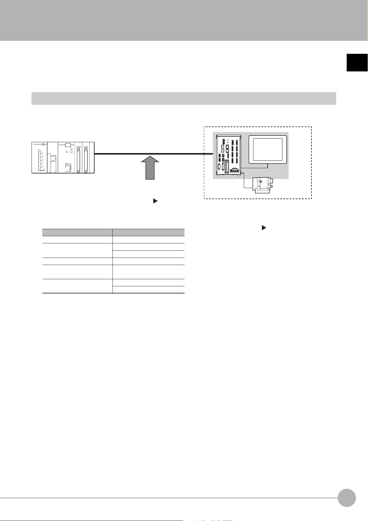
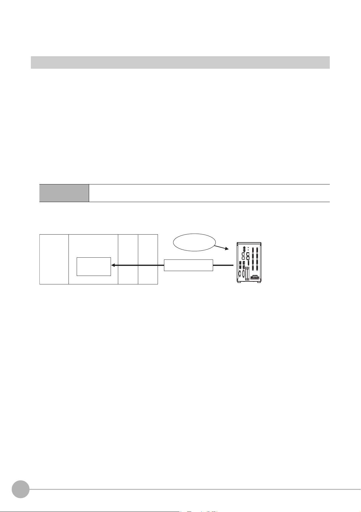
Confirming the System Configuration
Sensor Controller
External device (e.g, PLC)
Parallel Parallel I/O cable
Ethernet cablePLC Link
RS-232C cable
EtherNet/IP Ethernet cable
Ethernet cable
Ethernet cableNon-procedure
RS-232C cable
Camera
Communications protocol
Communications cable
EtherCAT (FH-1000 series/
FH-3000 series only)
An LCD monitor (BOX type only) for operation
and monitoring and a camera are connected to
the Sensor Controller unit.
For details, refer to the
Vision System FH/FZ5
Series User's Manual (Cat. No. Z365) and the
Instruction Manual that is provided with each
individual device.
The Sensor Controller is connected to an external device (PLC, etc.)
by a communication cable, and communication can be performed
using various communication protocols. Refer to Methods for
Connecting and Communicating with External Devices (p.43) for
information on the different communications protocols.
The FH/FZ5 are Vision Systems that perform measurement processing through a Sensor Controller on
measurement objects that are imaged by a Camera.
puter,
In a system configuration that is connected to a PLC, com
commands can be received from and measurement results can be output to the external device.
System Configuration
An overview of the FH/FZ5 series system configuration is given below.
or other external device, measurement
1
Overview
Vision System FH/FZ5 Series User’s Manual
for Communications Settings (Z342)
Confirming the System Configuration
13
Page 16
Communicating with an External Device
Trigger sensor
PLC
External device
External device
PLC
The measurement
results are output.
• Status signals
• Overall judgement
• Measured values
• Character output
Sensor Controller
Measurement triggers
and other control
commands are input.
This section gives the communications specifications, describes the control methods that you can use for
communications, and describes the settings that are required before starting communications with an external
device.
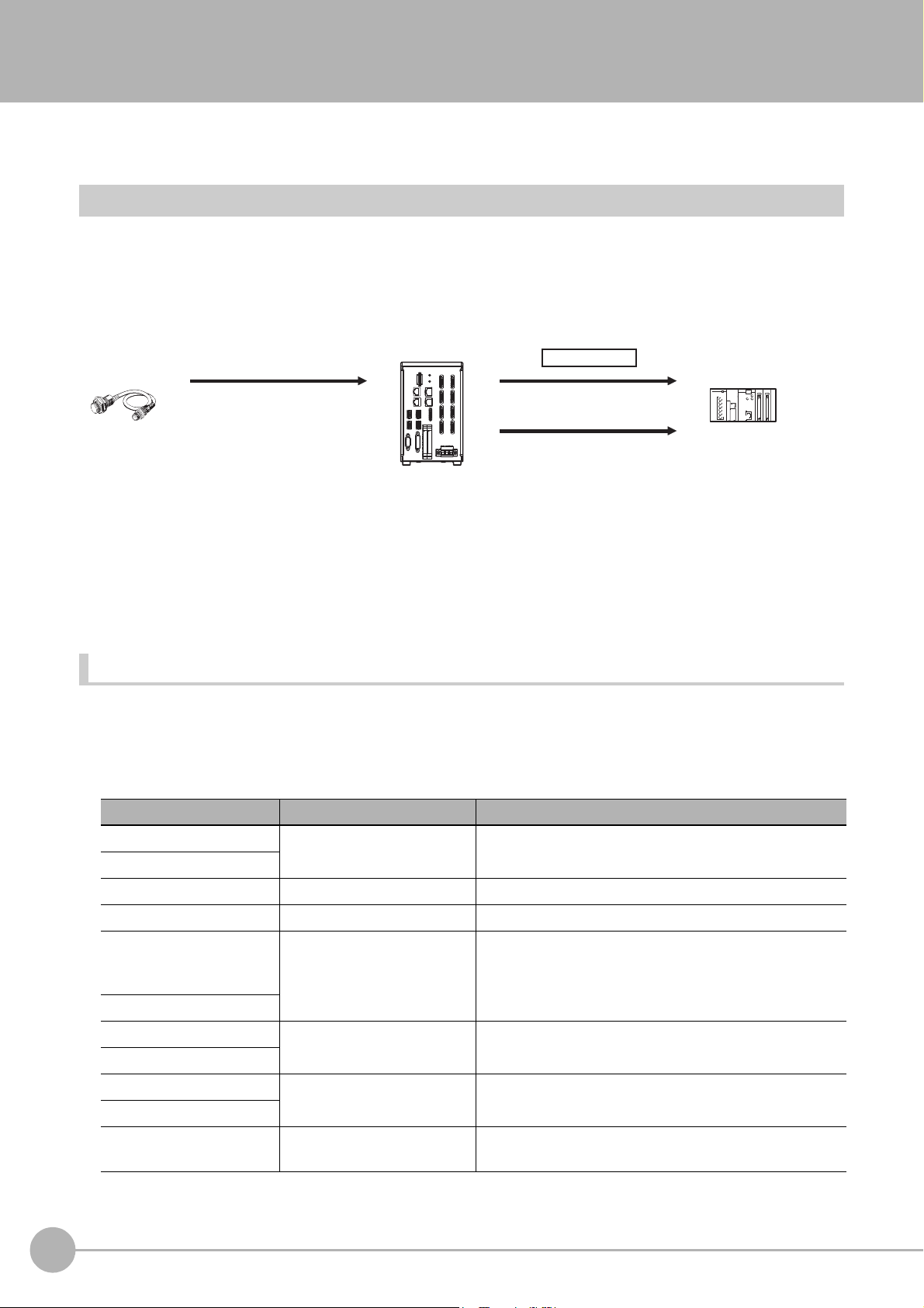
Basic Control Operations of the Sensor Controller
The following figure shows basic communications between an external device and the Sensor Controller and the
flow of signals and data.
The following methods can be used to exchange data between
Commands That Can Be Input to the Sensor Contro
Typ e Description
Control sig
(input signals)
Control
commands
Communications
comma
nals
nd input
Data Output to an External Device from th
Typ e Description
Status signals
Overall judgement
Measured values
A measurement is executed when a measurement trigger (i.e., an ON ST
For information on control signals, refer to Control with Control Signals and Status Signals
(p.22).
ou can send commands to perform measurements
Y
tasks. The communications commands depend on the communications protocol that you
use. Refer to the section for each communications protocol for details.
e Sensor Controller
When the Sensor Controller confirms a control
begins measurement processing, the status of the Sensor is reported to the external device
through status signals (e.g., a BUSY signal).
For information on status signals, refer to Control with Control Signals and Status Signals
(p.22).
NG is output whenever there is one or more NGs i
processing items.
The overall judgement can be output through the OR signal or through the TJG output
parameter.
*1: This behavior can be changed in the settings.
For information on the OR signal, refer to Control with Control Signals and Status Signals
(p.22).
For information on the TJG output parameter.
The measured values from processing items can be output. The output items must be
processing items for output and registered as output data (data 0 to data 7). Refer to
Settings Required for Data Output (p.29) for details. You can also use commands to obtain
results after a measurement is performed.
*1
ller from an External Device
an external device and the Sensor Controller.
EP signal) is input.
, change scene groups, or perform other
nal or communications command input and
sig
the judgement results for multiple
n
14
Communicating with an External Device
Vision System FH/FZ5 Series User’s Manual
for Communications Settings (Z342)
Page 17

Typ e Description
Note
Character output (PLC Link
or non-procedure
communications only)
You can also use the FTP server to obtain logged image files and logged data files saved in the FH/FZ5 (or in external
memory) from a web
browser or FTP client.
You can output character strings and numbers that are read by proce
Character Inspection, Barcode, or 2DCode. Refer to Items that Can Be Output as Output
Data (p.28) for details.
You can also use commands to obtain results after a measurement is performed.
ssing items such as
1
Overview
Vision System FH/FZ5 Series User’s Manual
for Communications Settings (Z342)
Communicating with an External Device
15
Page 18
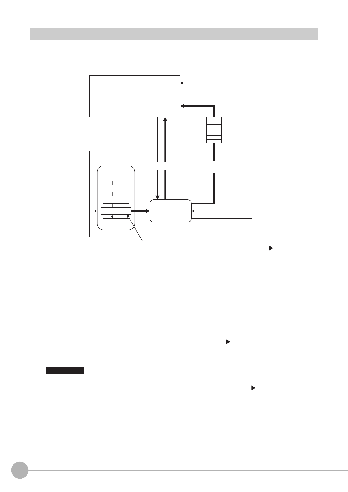
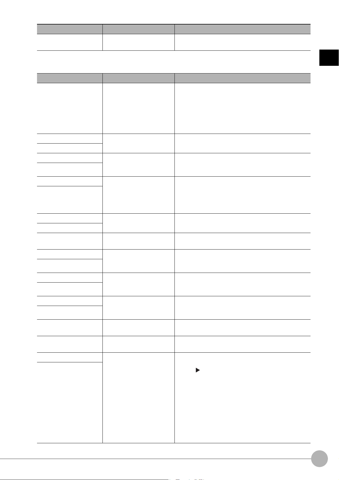
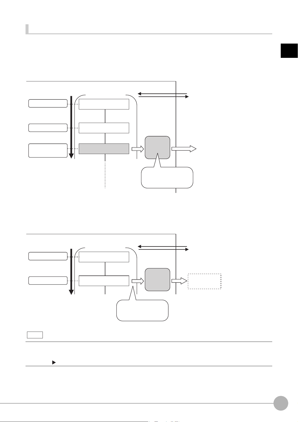
Communication between the Sensor Controller and an External Device
PLC or other external device
Camera Input
Search
Output Unit
Measurement
flow
Sensor Controller
Communications
Module
Communications processing
Example: Starting a
measurement, etc.
Response
Data output request
(DSA signal)*1
Result Completion signal (GATE signal)*1
(1) Command
Communications
processing
(2) The data at this
point is output to the
Communications
Module.
An Output Unit processing item is required to
perform data output. (Multiple Output Unit items
can be used.)
(3) Data
output
*1: When output control is set to [Handshaking]
(data output is controlled by the DSA and
GATE signals). Refer to Control with
Control Signals and Status Signals (p.22).
IMPORTANT
Communication between the Sensor Controller and external device takes place as shown below.
The following figure shows the flow when a communications command is used to start a measurement and then
output d
ata.
*2: If handshaking is used for output control, the measurement data will remain in the Communications Module in a standby state
16
Communicating with an External Device
(1) When the Sensor Controller receives a command from a PLC or
other external device, it executes the
command and returns a response.
(2) The data obtained after the measurement is performed is
output via the Communications Module by
the Output Unit (an abbreviation for Results Output Unit) processing item in the measurement flow.
(3) The measurement data is output when the Output Unit is executed, n
actually finished.(*2)
until a data output request (DSA signal) is received from an external device. Refer to Data Output Control with Handshaking
(p.32).
To output data, you must place an Output Unit processing item in the measurement flow.
You can place multiple Output Unit processing ite
Data Output (p.29).
ms in the measurement flow. Refer to Settings Required for
Vision System FH/FZ5 Series User’s Manual
ot when the measurement is
for Communications Settings (Z342)
Page 19
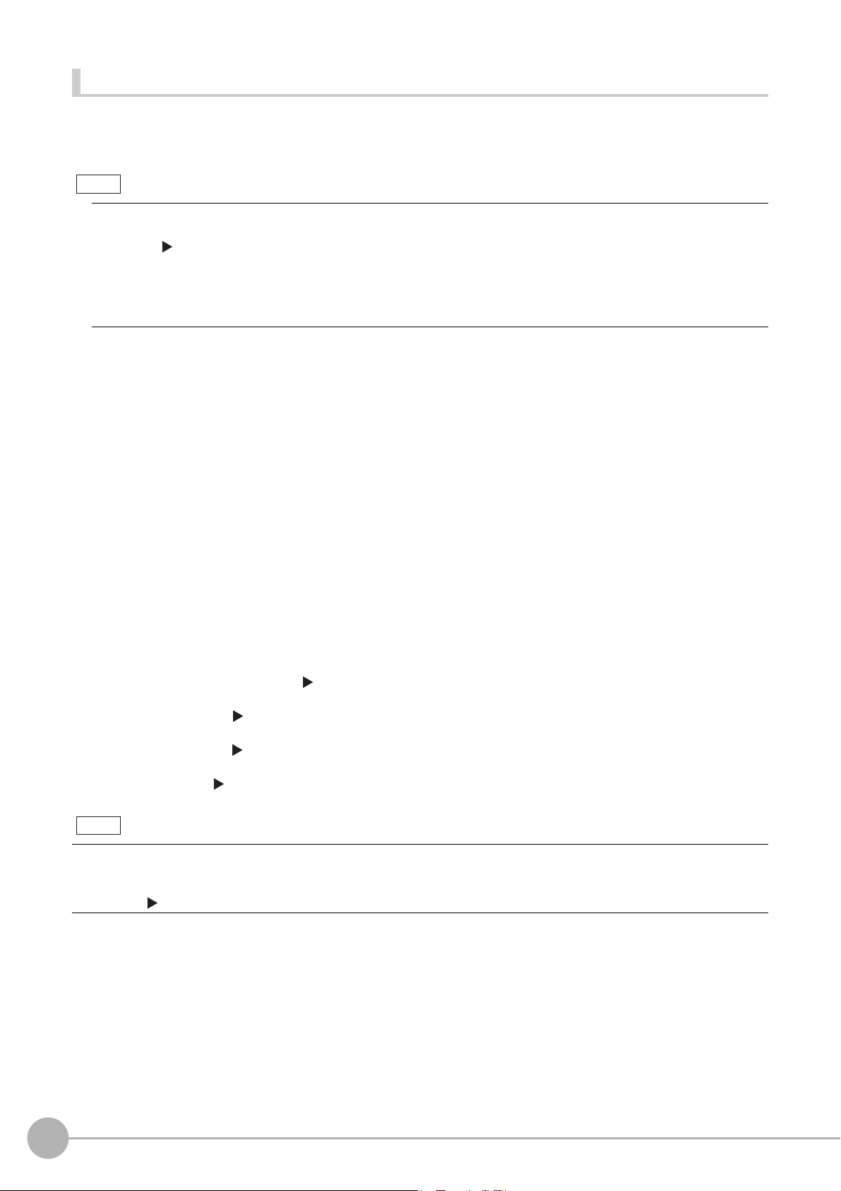
Control Methods for the Sensor Controller
There are three methods that you can use to control the Sensor Controller from a PLC or other external device.
They are described in this section.
For details on each control method, refer to their corresponding section.
Control Methods
Method Overview Trigger type or area Signals or area used
n is controlled by the
trol commands. The
ON/OFF status of the control
sig
nals and status signals
The control command code is
stored in the I/
PLC and then the Request Bit is
turned ON.
O m
emory of the
Control signals and status
signals
PLC I/O memory (Com
Area
and Response Area)
mand
Control signals and
status signals
Control with
commands and
responses
Operatio
ON/OFF status of the
Measurement Trigger Signal
(STEP) and Command Request
Bit (EXE).
Control is performed by sending
con
execution results of the
command can be confirmed in
the response from the Sensor
Controller.
1
Overview
Data output after
me
asurement
s
After a measurement is
pe
med, the previously
rfor
specified measurement data is
output automatically.
Not required. (Output is
p
rmed automatically after
erfo
measurement.)
PLC I/O memory (Data Output
Area)
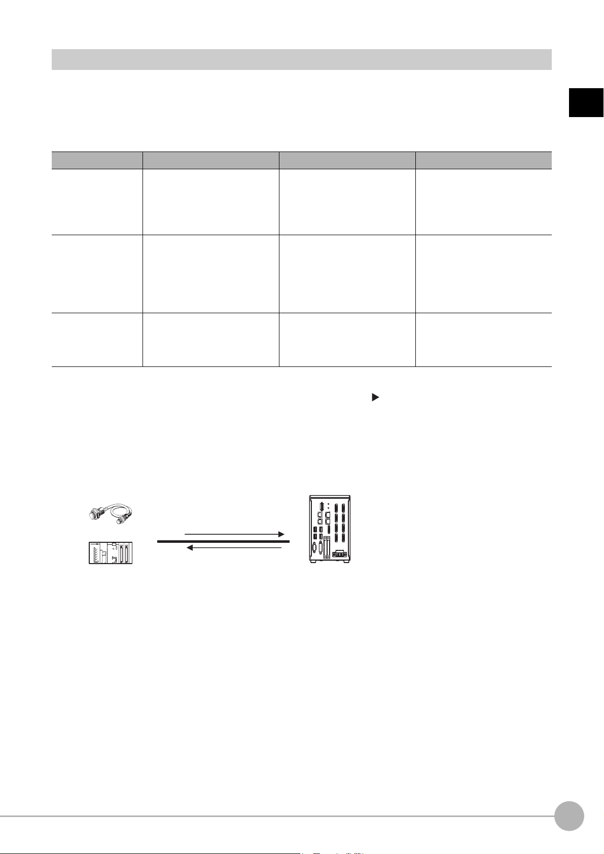
1 Control with Control Signals and Status Signals (Refer to Control with Control Signals and
Status Signals (p.22))
Control and status confirmation for the Sensor Controller is performed with the ON/OFF status of the
control and status signals.
s m
This method is best suited for basic operations such a
status of the Sensor Controller.
Trigger sensor
External device
Control signal
Status signal
Sensor Controller
easurement triggers or to check the operating
Vision System FH/FZ5 Series User’s Manual
for Communications Settings (Z342)
Communicating with an External Device
17
Page 20
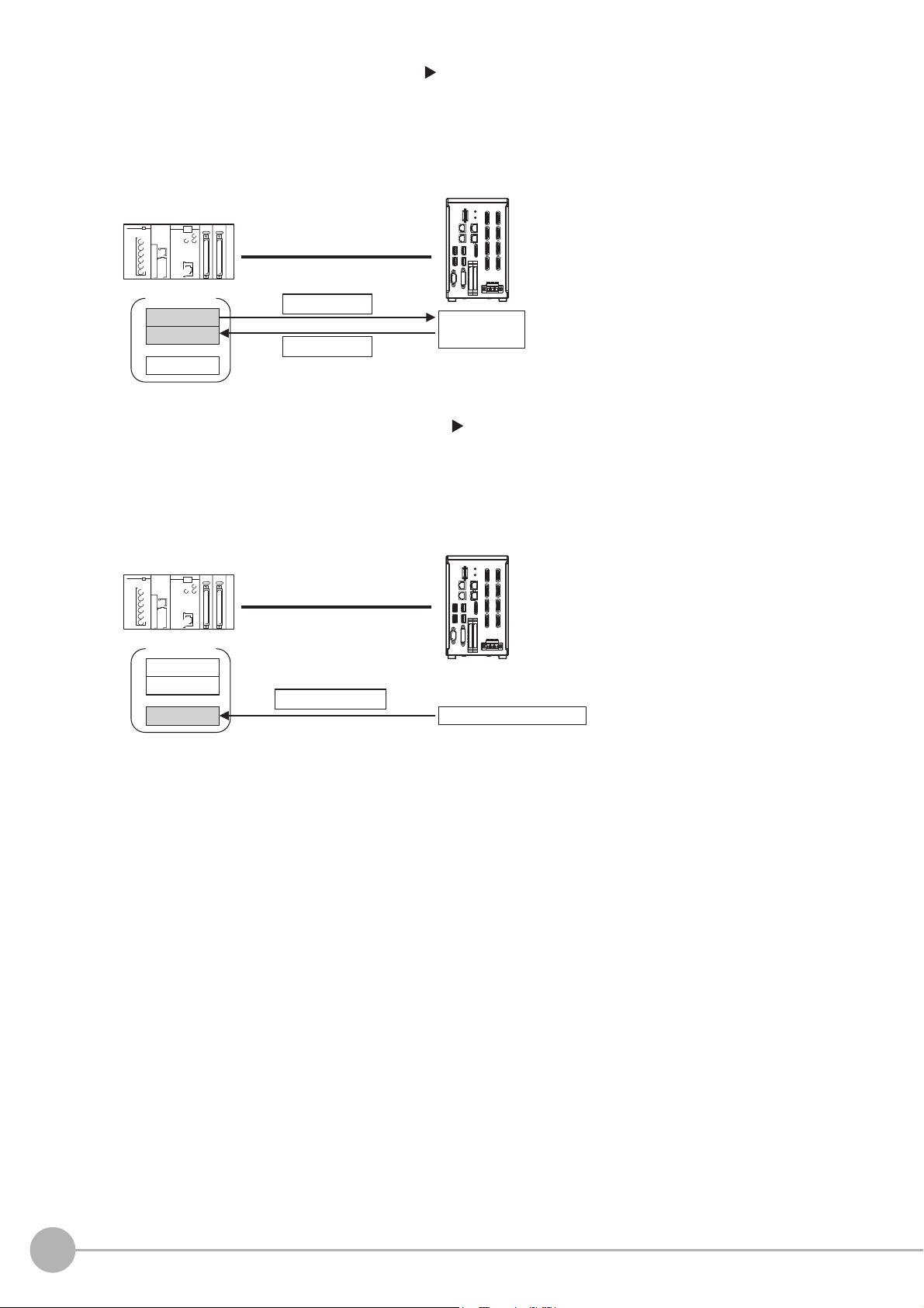
2 Command/Response Method (Refer to Command/Response Method (p.25))
External device
I/O memory
Sensor Controller
Command Area
Response Area
(1) Command
(3) Response
Output Area
(2) Command
execution
Control is performed by storing the control command and the response to that command in the I/O
memory of a PLC.
ands
This method is best suited to send multiple comm
to the Sensor Controller without using PLC
communications instructions.
3 Data Output after Measurements (Refer to Data Output after Measurements (p.26))
After a measurement is executed, the measurement data specified for output is automatically output to the
specified words in the I/O memory of the PLC.
This allows you to output measurement results from the Sensor Controller to the PLC automatically
ut h
witho
External device
aving to send data requests from the PLC.
Sensor Controller
I/O memory
Command Area
Response Area
Output Area
(2) Measurement data
(1) Measurement processing
18
Communicating with an External Device
Vision System FH/FZ5 Series User’s Manual
for Communications Settings (Z342)
Page 21
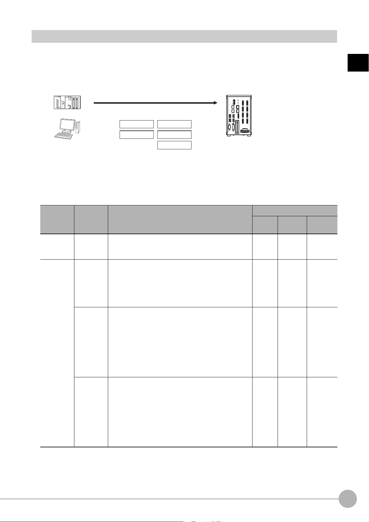
Communication Protocols for Communication with the Sensor Controller
PLC
Computer
EtherNet/IP
EtherCAT
Non-procedure
Parallel
PLC Link
Sensor Controller
Control can be performed through different communications protocols.
The Sensor Controller can be controlled from a PLC, computer, or other external device using a variety of
communication protocols.
us
The communication protocols that can be
described below.
Applicable Communications Protocols
The communication protocols of each communication method that can be used with the Sensor Controller
are as follows:
OK: Supported, ---: Not supported.
Communi-
cations
method
Communi-
cations
protocol
ed to control the Sensor Controller from an external device are
Communications cable type
Overview
Parallel
I/O
Ethernet
RS-232C/
422
1
Overview
*2
Contact
inputs
Data
sharing
Parallel
PLC Link
EtherNet/IP
EtherCAT
(FH-1
000
series/FH3000 series
only)
Data is exchanged between an external device and the
Sensor Control
signals from multiple physical contacts.
Thi
s is OMRON’s communications protocol for Vision
System.
The control sig
area to store measurement data are assigned in the I/O
memory of the PLC, and data is exchanged cyclically to
share data between the PLC and the Vision System.
This is an open communications protocol.
Tag data links are used for communication with the
Sensor Con
On the PLC, structure varia
correspond to the control signals, command/response
data, and measurement data. These variables are then
used as tags to input and output data through tag data
links to exchange data between the PLC and the Sensor
Controller.
This is an open communications protocol.
PDO (process data object) communications are used to
co
mmun
I/O ports that correspond to the control signals,
co
mmand/respon
prepared in advance, and the variables assigned to those
I/O ports are used to input and output data via PDO
communications to exchange data between the PLC and
the Sensor Controller.
ler through combinations of ON/OFF
nals, Command Are
ler.
trol
*1
icate with the Sensor Controller.
se data, and measurement data are
a/Respo
bles are created
nse Area, and
that
OK --- ---
--- OK OK
--- OK ---
--- OK ---
Vision System FH/FZ5 Series User’s Manual
for Communications Settings (Z342)
Communicating with an External Device
19
Page 22

OK: Supported, ---: Not supported.
Communi-
cations
method
Frame
transmission
Communi-
cations
protocol
Nonproce
dure
Overview
Command frames are sent to the Sensor Con
response
frames are received from the Sensor Controller
troller and
without the use of any specific protocol.
Data can be exchanged between the PLC, computer, or
other exte
rnal device and the Sensor Controller by
Communications cable type
Parallel
I/O
Ethernet
RS-232C/
422
--- OK OK
sending and receiving ASCII or binary format data.
*1: When connected to a CJ-series PLC, specify the areas in the I/O memory.
*2: FH-1000, FH-3000, and FH-L series are able to connect via only RS-232C.
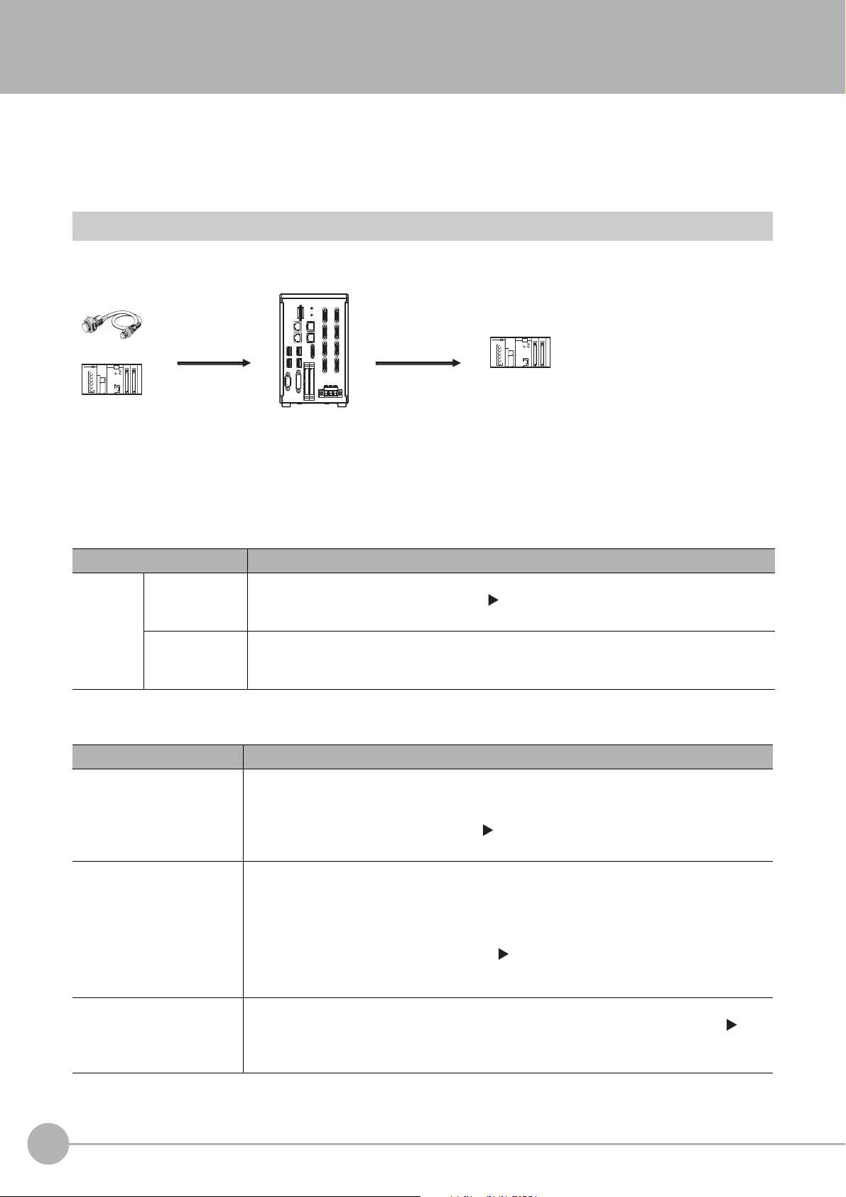
Saving Sensor Controller Data to an External Device
In addition to sending and receiving data via a communication protocol, you can also save Sensor Controller
data to an external device using the methods described below.
For details, refer to the V
ision System FH/FZ5 Series User's Manual (Cat. No. Z365).
Connecting the FH/FZ5 as an External Drive
In addition to the Sensor Controller's built-in RAM disk, you can directly save various types of data such as
scene data, scene group data, logged data, and logged images to the external media below.
• External Memory (Refer to Using External Memory Devices in the Vision System FH/FZ5 Series User's Manual
(Cat. No. Z365).)
Data can be saved directly to a
• Network Drive (Refer to Shared folder on a computer connected
User's Manual (Cat.
No. Z365).)
You can save data directly to a shared folder on
B memory stick or SD Memory Card inserted into the slot on the Sensor Controller.
US
to the network in the Vision System FH/FZ5 Series
a computer connected via Ethernet.
*2
Computer Sensor Controller
Ethernet
Saved directly.
Shared computer folder (the
shared folder settings must
be set on the computer)
• Logged images
• Logged data
The Sensor Controller is set
up to save to the shared
folder on the computer.
• Data Transfer (FTP Server) (Refer to Saving Data to an External Device in the Vision System FH/FZ5 Series User's
Manual (Cat. No. Z365).
You can move logged image files and other data saved in the Sensor Controller's RAM
)
disk or a USB memory stick to
a computer via Ethernet.
The computer must provide FTP client
to access the
FH/FZ5.
The computer cannot be accessed directly from the Sensor Controller.
Browser
(FTP client)
Computer
Ethernet
Access via FTP
Images files moved to the computer.
Sensor Controller (FTP server)
RAM disk
Image files
This enables you to move logged images off of the Sensor Controller’s RAM disk before it becomes full.
20
Communicating with an External Device
Vision System FH/FZ5 Series User’s Manual
for Communications Settings (Z342)
Page 23
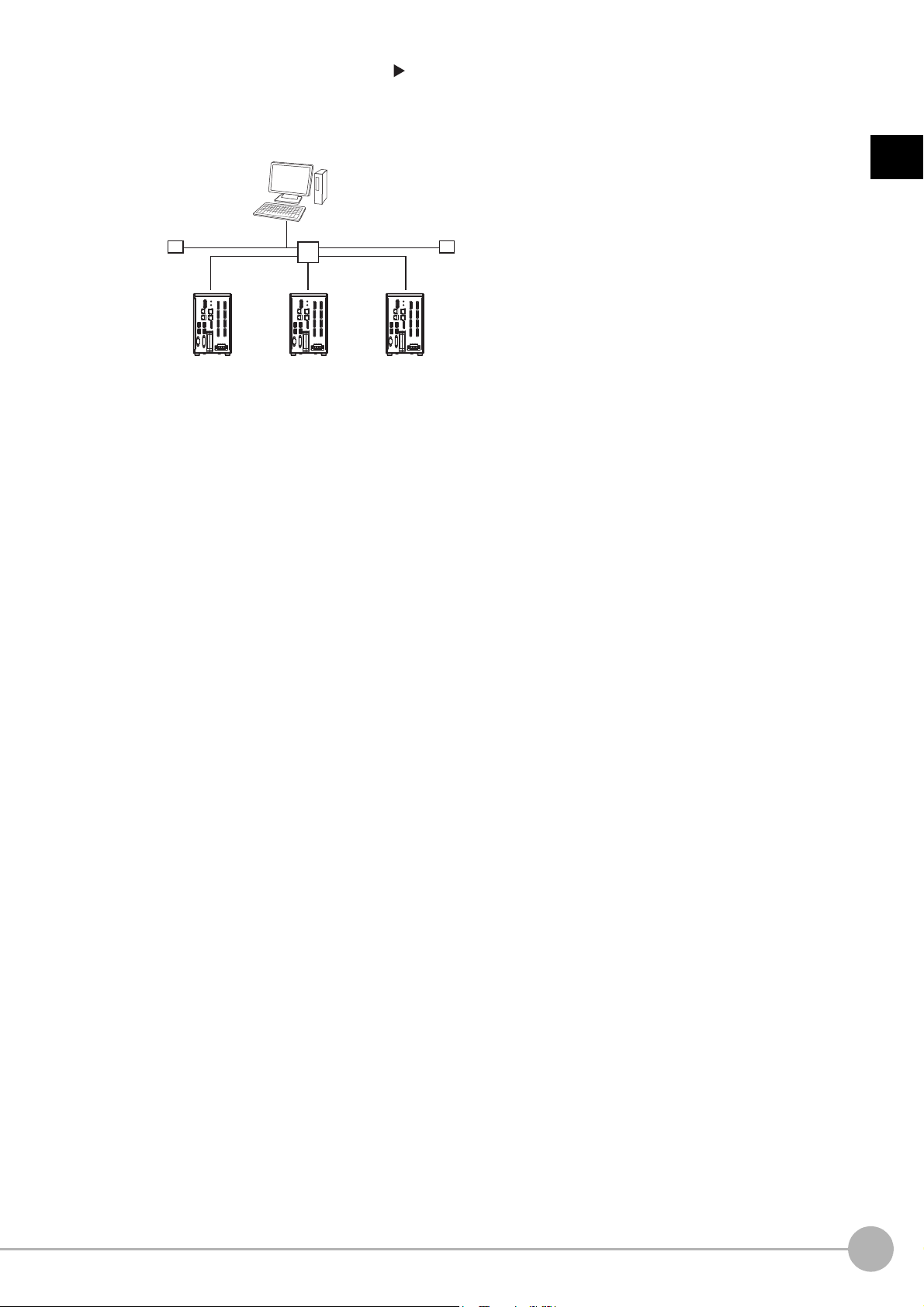
• Remote Operation over a Network (Refer to Remotely Operating the Controller (Remote Operation) in the Vision
Sensor
Controller
Ethernet
Computer (FH/FZ5 software)
Hub
Sensor
Controller
Sensor
Controller
Operate/monitor
System FH/FZ5 Series User's Manual (Cat. No
If more than one Sensor Controller is connected via Ethernet, a compute
Ethernet network can be used to operate and monitor all the Sensor Controllers at once.
. Z365).)
r (the FH/FZ5 Tool) connected to the same
1
Overview
Vision System FH/FZ5 Series User’s Manual
for Communications Settings (Z342)
Communicating with an External Device
21
Page 24
Control Methods Using an External Device
Trigger sensor Sensor Controller
(1) Measurement trigger input
(STEP signal: ON).
Control signal
(2) Command received.
(BUSY signal turned ON.)
(3) Judgement results are output.
(OR signal turned ON.)
Status signals
External device
This section describes the methods that you can use to control the Sensor Controller from a PLC or other external device.
Control with Control Signals and Status Signals
Control and status confirmation for the Sensor Controller is performed with the ON/OFF status of the control and
status signals.
Measurement triggers and other commands are input as control signals from the PLC.
The operating status of the Sensor, judgement results, an
d other st
status signals sent from the Sensor Controller.
(1) The external device turns ON the STEP signal to input a measurement trigger.
atus information can be confirmed through
(2) When the Sensor Controller confirms that the STEP signal is ON, it outputs the BUSY signal to the
external de
(3) When the Sensor Controller finishes the measurement, it
vice and begins a measurement.
outputs the judgement results on the OR
signal.
Control Signals and Status Signals
The signals that the Sensor Controller can input and output as control signals and status signals are described in
the following tables.
Input Signals (PLC to Sensor Controller)
Signal Signal name Function
EXE
Command Request
Trigger Measure Bit Turn ON this signal to execute measurements.
STEP Measure Bit Turn ON this signal to execute measurements.
DSA
(Used only for handshaking
output control.)
Result Set Request
Control Command Execution
Si
gnal
Da
ta Output Request Signal
rn ON this signal (from the PLC) to send a command to
Tu
the FH/FZ5.
Use this signal (from the PLC) during handshaking to
request from the F
output results from the execution of the measurement flow.
H/FZ5 the external output of the data
ERCLR
Error Clear
XEXE
Flow Command Request
DI (DI0 to DI7) Command Input Signals
22
Control Methods Using an External Device
Error Clear Bit
Flow Command Request Bit
Turn ON this signal to clear the ERR signal from the Sensor
Con
trol
ler.
Turn ON this signal to execute a command during
execution of PLC Link, fieldbus, or parallel flow control.
These signals are used to input commands from a parallel
in
terface.
Vision System FH/FZ5 Series User’s Manual
for Communications Settings (Z342)
Page 25
Signal Signal name Function
ENCTRIG
Encoder Trigger Input (Phase
A, Phase B, or Phase
Output Signals (Sensor Controller to PLC)
Signal Signal name Function
BUSY Busy Signal
FLG
Command Completion
Control Command Completion
Si
gnal
Z)
This is the encoder input signal. This signal is only used
when you use an encoder trigger.
This signal tells when new commands and other external
inputs
cannot be acknowledged during processing of other
external inputs.
Just because this signal is ON does not necessarily mean
that a
command is being executed. To check whether a
command is being executed, access the Command
Completion (FLG) signal.
The FH/F
command execution has been completed.
Z5 uses this signal to tell the user (PLC) that
1
Overview
GATE
Result Notification
READY
Trigger Ready
OR
Overall Judgment
DO (DO0 to DO15) Data Output Signals
XFLG
Flow Command Completion
XBUSY
Flow Command Busy
XWAIT
Flow Command Wait
Data Output Completion
Si
gnal
Camera Image Input Enabled
Signal
Overall Judgement Output
Signal
Flow Command Completion
Bit
Measurement Command Busy
Bit
Measurement Command Wait
Bit
gnal tells the timing to load the output data to the
This si
User (PLC).
Data output is enabled when this signal is ON.
This signal indicates when the STEP (Measurement
Trigger) signal or the Trigger signal can be input.
When using the multi-input function, the succeeding STEP
or Trigger signals are accepted only after this signal turns
ON.
This si
gnal gives the results of the overall judgement.
These signals are used to output parallel data and parallel
ju
dgement
This signal tells when execution of a command that was
executed during execution of PLC Link or fieldbus flow
control has been completed.
This signal tells when a command that was input during
execu
executed.
This signal tells when input of a command can be
acknowledged du
flow control.
s through a parallel interface.
tion of PLC Link or fieldbus flow control is being
ring execution of PLC Link or fieldbus
*1
*2
*3
Trigger ACK
Command Ready
ERR
Error Status
Vision System FH/FZ5 Series User’s Manual
for Communications Settings (Z342)
Trigger Signal Acknowledged
Bit
Command Execution Ready
Bit
Error Signal
The FH/FZ5 uses this signal to acknowledge reception of a
T
rigger signal.
This signal tells when control command can be executed.
The FH/FZ5 provides notification with this signal when it
de
tects the following errors.
Refer to Erro
ision System FH/FZ5 Series User's Manual (Cat.
V
Z365).
• Camera connection error
• Battery error
• Fan error
Th
e ERR signal does not turn OFF even after the error is
eliminated. The signal turns OFF only when the error status
is cleared by a control command.
r Messages and Troubleshooting in the
No.
• System error
• Communications timeout
• STEP input during
measureme
Control Methods Using an External Device
nt
23
Page 26

RUN
Run Mode
Signal Signal name Function
This is a notification signal indicating the FH/FZ5 Sensor
Measurement Mode Signal
Controller is in Run mode (In a measurement capable state
with [RUN signal output] checked in the Layout settings for
the currently displayed line).
ACK Command Completion Flag
SHTOUT Exposure Completion Signal
STGOUT Strobe Trigger Output
*1: This signal is linked to the Output Unit processing items in the measurement flow.
It is not associated with the BUSY signal. It is not related to the parallel interface OR signal. Note that the operation is different
when using PLC Link. See Communicating with PLC Link (p.162).
*2: This signal is always OFF during display of a through image.
If you use a Camera with Lighting Controller, the time required
increase in comparison with not using a Camera with a Lighting Controller.
For details, refer to Camera Image Input
Items Reference Manual (C
*3: The OR signal is output only when the [Output] option is selected in the Adjustment Window.
at. No. Z341).
FH or Camera Image Input HDR in the Vision System FH/FZ5 Series Processing
This signal tells when execution of the DI command has
be
en completed
.
This signal tells when Camera exposure has been
completed.
This is the trigger signal for the strobe.
or the READY or Trigger Ready signal to turn OFF may
f
24
Control Methods Using an External Device
Vision System FH/FZ5 Series User’s Manual
for Communications Settings (Z342)
Page 27
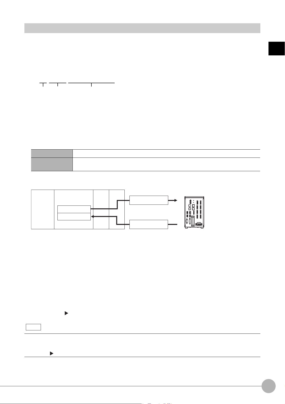
Command/Response Method
DI7 DI6 DI4 DI3 DI2 DI1 DI0
Execution
Command
Command information
DI5
(1) Command Area
(5) Response Area
(2) Command
(4) Response
PLC
CPU Unit
I/O memory
(communications areas)
• Switch Scene Number
• Single Measurement, etc.
OK, etc.
(3) Command is processed.
Sensor Controller
Note
Parallel
Commands are input to the Sensor Controller by turning the DI signals (DI0 through DI7) ON and OFF. There
is no direct response to these commands. Confirm whether a command was received by checking the ACK
signal. With an FZ5-series Controller, you can check the BUSY status signal instead of the ACK signal.
The command code is input with signals DI0 through DI6, and the command is executed by turning ON DI7.
PLC Link, EtherNet/IP, or EtherCAT
Command/response control signals can be exchanged by storing control commands from the PLC to the
Sensor Controller and responses from the Sensor Controller to the PLC in the I/O memory of the PLC. This
enables you to send single measurement and scene switch requests to the Sensor Controller without any
sequence control with communications commands from the PLC.
Memory Areas Used by the Command/Response Control Method
Command Area You write the control commands to execute for the Sensor Controller to this area.
Response Area
You read the results of executing the control commands that
from this area.
were written to the Command Area
1
Overview
Flow of Communications between the PLC and the Sensor Controller
(1) The PLC (the user) writes a control command to a specified PLC I/O memory area (the Command
Area).
(2) The PLC (the user) then turns ON the EXE bit to send the control command to the Sensor Controller.
(3) The Sensor Controller executes the received control command.
(4) The Sensor Controller returns a response to the PLC after the control command is executed.
(5) The PLC (the user) stores the response in a specified PLC I/O
The available control commands depend on the communication
Refer to the Command List (p.355).
Command-driven character string output is
EtherCAT.
To output character strings, send the commands using EtherNet/IP me
Refer to the Communicating with the Sensor Controller with EtherNet/IP
Vision System FH/FZ5 Series User’s Manual
for Communications Settings (Z342)
mory area (the Response Area).
me
s protocol that is used.
not supported when using EtherNet/IP tag data link communication or
ssage communication.
Message Communications (p.264)
Control Methods Using an External Device
25
Page 28
Non-procedure Communications
Data
Output Area
• Specified data is automatically output.
• Output characters
(2) Data
CPU Unit
PLC
I/O memory
(communications areas)
Sensor Controller
Measurement
execution
(1)
Communications commands are sent to the Sensor Controller through sequence control in the PLC. An
external device and the Sensor Controller communicate through non-procedure (normal) communications.
Data Output after Measurements
After a Single Measurement or Start Continuous Measurements command is executed, the Sensor Controller
automatically outputs the data that corresponds to the measurements that have been specified as output items
to the PLC. This allows you to easily pass measurement results data from the processing items to the PLC. You
can also choose to output only when the PLC meets the conditions that are required to receive the data (i.e.,
when handshaking is turned ON).
The output destination for data depends on the protocol th
at is used to
device and the Sensor Controller, as described below.
PLC Link, EtherNet/IP, or EtherCAT
The output data is automatically output to the following area that is specified PLC I/O memory.
Area of Memory Used for Data Output after Measurement
communicate between the external
Data Output Area
The output data for the measurement is written to this are
of the measurement.
a by the Sensor Controller after execution
Flow of Communications between the PLC and the Sensor Controller
The data to output after measurement and the PLC I/O memory area (Data Output Area) to store that data
are specified in advance. (Reference: Settings Required for Data Output (p.29).)
(1) Measurement is executed.
emen
(2) After a measurement is executed, the specified measur
t data is stored in the Data Output Area
in the PLC.
Parallel
The output data is output to the PLC signal wires via the DO signals (DO0 to DO15).
Non-procedure Communications
The output data is output to the PLC reception buffer through non-procedure (normal) communications.
26
Control Methods Using an External Device
Vision System FH/FZ5 Series User’s Manual
for Communications Settings (Z342)
Page 29
Outputting the Output Data
Search measurement
results output.
Processing
order
Measurement started.
0.Camera Image Input
1.Search
2.Data Output
Communications
Module
Measurement flow
Sensor Controller
Measurement executed.
Processing started
(BUSY).
Single Measurement
command
The results for
measurements for
1. Search are output.
Processing
order
Measurement started.
0.Camera Image Input
1.Character Inspection
Communications
Module
Measurement flow
Sensor Controller
Measurement processed.
Processing started
(BUSY).
Single Measurement
command
Characters are output
at the same time that
the characters are read.
Read charac-
ters are output.
Note
The measurement data is output to the external device via the Communications Module by the Data Output
processing unit located in the measurement flow.
t Un
Therefore, to output measurement data, you must place an Outpu
The measurement data is output when the Output Unit is execute
finished.
it processing unit in the measurement flow.
d, not when the measurement is actually
1
Overview
You can output character strings that were read by processing items that read characters, such as Character
Inspection, Barc
Character strings are output simultaneously
Command-driven character string output is not supported when using EtherNet/IP tag data link communication or
EtherCAT.
To output character strings, send the commands using EtherNet/IP me
Refer to the Communicating with the Sensor Controller with EtherNet/IP Message Communications (p.264)
ode, or 2DCode. (You must use PLC Link communications to do this.)
when
the processing item is executed.
ssage communication.
Vision System FH/FZ5 Series User’s Manual
for Communications Settings (Z342)
Control Methods Using an External Device
27
Page 30
Items that Can Be Output as Output Data
Note
Note
Measurement Data
You can output up to eight items (32 bytes) with one Output Unit processing unit.
• If you need to output nine or more data items, set more than one Output
flow.
Refer to Outputting Multiple Measurement Data Items (p.30).
• The number of data items that can be output by
setting when using PLC Link or EtherCAT communications, as described below.
• PLC Link: 256 max. (1,024 bytes max.)
• EtherCAT: 64 max. (256 bytes max.)
one Output Unit processing unit can be increased by changing a
Unit processing unit in the measurement
The following items can be output:
• Judgement result
• Measured parameters (correlation values, reference coordinates, etc.)
• Results calculated based on the values of the measured parameters
• Judgement results from expression results (Parallel Judgement Output)
Character Output (PLC Link Communications or Non-procedure Communications Only)
You can output the characters that were read by processing items such as Character Inspection.
• Character output is supported only for PLC Link communications or non-procedure communications.
• Maximum number of output chara
• Character Inspection: 32 characters
• Barcode:1024 characters
• 2DCode: 652 characters
• OCR: 128 characters (32 characters × 4 lin
• T
he Read string is output as NULL(/0).
cters are as follows.
es)
The processing items that support character output are listed below.
Refer to the descriptions for each processing item for d
• Character Inspection (Refer to Character Inspection in the Vision System FH/FZ5 Series Processing Items
Reference Manual (Cat. No
• Barcode (Refer to Barcode in the V
Z341).)
• 2DCode (Refer to 2
Z341).)
• OCR (Refer to OCR in the Vision System FH/FZ5 Series Processin
Command-driven character string output
EtherCAT.
To output character strings, send the commands using EtherNet/IP me
Refer to the Communicating with the Sensor Controller with EtherNet/IP
. Z341).)
DCode in the V
is not supported when using EtherNet/IP tag data link communication or
ision System FH/FZ5 Series Processing Items Reference Manual (Cat. No.
ision System FH/FZ5 Series Processing Items Reference Manual (Cat. No.
etails on the character output format.
g Items Referen
ssage communication.
Message Communications (p.264)
ce Manual (Cat. No. Z341).)
28
Control Methods Using an External Device
Vision System FH/FZ5 Series User’s Manual
for Communications Settings (Z342)
Page 31

Settings Required for Data Output
Use the following procedure to set up Output Unit processing units for data output.
Measurement Data
1 Place the output data in the processing flow.
Place the processing unit for data output in the measurement flow.
Processing Units That Serve as Output Units
The processing items under [Output result] in the processing item tree in the Flow Editor serve as Output
Units.
Output Unit Selection
Select the Output Units according to the communications protocol based on the combinations that are
shown in the following table.
For information on communications protocols, refer to Communication Protocols for Communication
with the Sensor Controller (p.19).
OK: Data can be output, ---: Data cannot be output.
1
Overview
Communications protocol
Output unit
Parallel Data Output OK --- --- --- ---
Parallel Judgement Output OK --- --- --- ---
Data Output --- OK --- --- OK
Fieldbus Data Output --- --- OK OK ---
Parallel PLC Link EtherNet/IP EtherCAT
2 Set the items to output.
Set the items to output as output data in the Output Units that you have placed in the measurement flow.
Refer to the descriptions for the communications protocol for
items in the Output Units.
Character Output (PLC Link Non-procedure Communications Only)
Set the character output settings for processing items that read output characters, such as Character
Inspection.
The character output operation is
set an Output Unit in the measurement flow.
Refer to the descriptions for individua
output.
• Character Inspection (Refer to Character Inspection in the Vision System FH/FZ5 Series Processing Items
Reference Manual (Cat. No
• Barcode (Refer to Barcode in the V
Z341).)
• 2DCode (Refer to 2
Z341).)
DCode in the V
executed by th
l proc
. Z341).)
ision System FH/FZ5 Series Processing Items Reference Manual (Cat. No.
ision System FH/FZ5 Series Processing Items Reference Manual (Cat. No.
e above processing items. In this case, it is not necessary to
essing items for details on the settings required for character
the specific procedures to set the output
Non-
procedure
Vision System FH/FZ5 Series User’s Manual
for Communications Settings (Z342)
Control Methods Using an External Device
29
Page 32

• OCR (Refer to OCR in the Vision System FH/FZ5 Series Processing Items Reference Manual (Cat.
Note
Processing
order
Measurement started.
Search measurement
results output.
0.Camera Image Input
1.Search
4.Data Output
Communications
Module
Measurement flow
Sensor Controller PLC
Command
Area
I/O memory
Response
Area
Output Area
2.Data Output
3.Position Compensation
The data that is output
first is overwritten by the
second data output
Position compensa-
tion values output.
No. Z341).)
Command-driven character string output is not supported when using EtherNet/IP tag data link communication or
EtherCAT.
To output character strings, send the commands using EtherNet/IP message communication.
Refer to the Communicating with the Sensor Controller with EtherNet/IP
Message Communications (p.264)
Outputting Multiple Measurement Data Items
Using Multiple Output Units for Data Output
You can register more than one Output Unit in the measurement flow.
If you want to output different types of data during measure
more than nine different data items, you must register multiple Output Units in the measurement flow.
ment flow processing, or if you want to output
Data output is executed for each Output Unit set in the measureme
data is the same PLC I/O memory area (the Data Output Area).
In this case, the output data that is
output first will be overwritten by
one of the following methods if you want to save all the output data.
nt flow, but the output destination for that
any output data written afterwards. Use
Offsets (PLC Link Communications Only)
When you use multiple Output Units to output data, you can offset the write destination of the output data
for each Output Unit.
Set the [Offset] for the Data Outpu
Registration) (p.232).
30
Control Methods Using an External Device
t pr
ocessing item. Refer to Output Data Settings (Processing Item
Vision System FH/FZ5 Series User’s Manual
for Communications Settings (Z342)
Page 33

Controlling Data Output with Handshaking
Note
16 bits
Parallel data output
PLC
0. Measurement data 0
7. Measurement data 7
Reception
buffer
Data output order
Measurement
data 7
Measurement
data 0
GATE
signal
DO0 to DO15
signals
ON
OFF
If handshaking is used to control data output, the timing of outputting the data is controlled by I/O signals.
Each time that data is output, read the output data and move it to a dif
ferent part of I/O memory in the
PLC.
Refer to Data Output Control with Handshaking (p.32).
For ASCII data output through non-procedure communications, you can append a record separator after each output
data item. (The default is the delimiter.)
The following two types of output units can be used via parallel communications:
Output unit Output data
Parallel Data Output The measurement data is output. A maximum of eigh
The judgement results are output. A maximum of
items can be output. The following two types of judgement results can be
Parallel Judgement Output
output:
• Judgement results for specified processing items
• Judgement results of set judgement conditions for the specified item
values
t items can be output.
16
judgement result
1
Overview
Parallel Data Output Units and Parallel Judgment Output Units are output in the order they are processed
in the measurement flow.
Outputting Multiple Items with Parallel Data Output
The items that are set for output data numbers 0 through 7 via parallel data output are output to the PLC
reception buffer in ascending order, one data item at a time (16-bit units). Each time a data item is output, the
GATE signal turns ON.*1
tput to the PLC reception buffer (data 0) is overwritten by the
When this occurs, the first data item that wa
next output data item (data 1).
Therefore, the data output to the PLC reception buffer
signal turns ON for each data item.
*1: The operation of the DSA signal depends on whether handshaking for output control is enabled. Reference: Data Output
Control with Handshaking (p.32).
s ou
m
ust be saved to PLC memory each time the GATE
Vision System FH/FZ5 Series User’s Manual
for Communications Settings (Z342)
Control Methods Using an External Device
31
Page 34

Data Output Control with Handshaking
External device
(1) DSA signal
(3) Measurement results output
(2) GATE signal
Sensor Controller
The timing for data output can be controlled through the DSA and GATE signals.
This is useful when receiving output dat
a from multiple Output Units, because it enables you to control the timing
for transferring output data.
Requirements for Using Data Output Control with Handshaking
To use data output control, set the output control method to [Handshaking] in the communications protocol
settings. For details, refer to Communications Specifications Settings for e
ach communications protocol.
Parallel Communications: Refer to Communications Specifications Settings (p.303).
PLC Link Communications: Refer to Communications Specifications Settin
gs (p.1
66).
EtherNet/IP and EtherCAT Communications: Refer to Communications Specifications Settings (p.63 or
p.222).
Handshaking
If the external device does not turn ON the DSA signal, the measurement data will not be output to the
external device from the Sensor Controller.
While the DSA signal is ON, the GATE signal turns ON when the measurement data is output from the
nsor Co
Se
The external device receives the measurement data when the GATE signal turns ON.
ntroller.
Signals Used for Handshaking
Signal Name Description
DSA
GATE
*1: If handshaking is not enabled for output control, the GATE signal will also be turned ON when data is output from the Sensor
Controller. However, if handshaking is disabled for output control during PLC Link communications, the GATE signal is not
even output.
Data Output Request
Signal
Data Output Completion
Signal
his signal is sent from the external device (PLC) to the Sensor
T
Controller to request data output.
T
his signal is sent by the Sensor Control
to tell the PLC when to receive the output data. This signal is sent only
while the DSA signal is ON.
*1
ler to the external device (PLC)
(1) The PLC turns ON the DSA signal and waits for the output data.
(2) The Sensor Controller turns ON the GATE signal when the DSA signal is ON
and it is ready to output
the measurement results(*1).
32
Control Methods Using an External Device
(3) The Sensor Controller turns ON the GATE signal and outputs the output data.
*1: This is when an Output Unit in the measurement flow is executed.
Vision System FH/FZ5 Series User’s Manual
for Communications Settings (Z342)
Page 35

DSA Signal ON Timing
Start measurement.
OFF
ON
Processing items related to results output
Processing item
DSA (data output request) signal status
Measurement flow
No data output.
Data output started.
DSA (data output request) signal status
Measurement flow
Data output started.
Start measurement.
Processing items related to results output
Processing completed.
OFF
ON
Output Unit 2 executed. Output Unit 1 executed.
Wait for the
first output data.
Measurement trigger
(e.g., STEP signal)
Data Output Request
(DSA) signal
Result Completion
(GATE) signal
Output data
(DATA 0 to 7)
Wait for the
second output data.
ON
OFF
ON
OFF
ON
OFF
(2) (3) (4) (5) (6) (1)
First
output data
Second output data
Turn ON the DSA signal when you want to receive data.
The Sensor Controller will output data when
output, and it detects that the DSA signal is ON.
an Output Unit has been executed, there is data waiting to be
1
Overview
To output measurement results immediately, execute the m
easurement trigger and turn ON the DSA signal.
The Sensor Controller does not monitor when the DSA signal changes from OFF to ON. It only chec
ON state.
Therefore, the measurement results will
be output from the Sens
or Controller to the external device
immediately after an Output Unit is executed and the output data must be received by the PLC at this time.
Receiving Multiple Continuous Output Data Items
When receiving multiple output data items from multiple Output Units, use the DSA and GATE signals to
receive the items one at a time.
Example: PLC Link Communications with Hand
shaking
ks for the
Vision System FH/FZ5 Series User’s Manual
for Communications Settings (Z342)
Control Methods Using an External Device
33
Page 36

1 When the first data is received, the user (PLC) turns ON the measurement trigger and
the DSA signal.
2 The Sensor Controller turns ON the GATE signal when the DSA signal is turned ON and
outputs the first data.
3 The user (PLC) turns OFF the DSA signal again when the GATE signal turns ON. Then,
the user (PLC) confirms the output data received in the PLC Data Output Area and
moves the received data to another area in PLC I/O memory.
4 The Sensor Controller confirms that the DSA signal is OFF and automatically turns OFF
the GATE signal.
5 The user (PLC) then turns ON the DSA signal again after the output data is received and
the GATE signal is turned OFF, and waits for the second data.
6 When the second data is output, the second data output is received when the GATE
signal is turned ON and steps 3 and 5 above are repeated.
Steps 3 through 5 above are repeated for all subsequent data output items.
34
Control Methods Using an External Device
Vision System FH/FZ5 Series User’s Manual
for Communications Settings (Z342)
Page 37

Setting Procedures for Communications
Note
This section gives an overview of the setting procedure up to the point that the Sensor Controller starts
communication with the PLC or other external device, and explains the communication modules used for
communication.
For connection with a Touch Panel Monitor, refer to Settings for Touch Panel Monitor in the Vision System FH/FZ5
Series User’s Manual (Cat. No. Z
Communications Setup Procedures
To communicate with an external device, the settings below are configured.
1. Setting the Communications Module.
(Sta
rtup settings)
↓
365).
· · · The communication method to be used is determined by selecting a
communica
Settings (Startup Settings) (p.62) for each communication protocol in
Methods for Connecting and Communicating with External Devices.
tion modul
e. For details, refer to Communications Module
1
Overview
2. Setting communications specifications. · · · The communications specifications are
of the Communications Module that was selected in step 1.
Set the communications area assignments for exchanging data with the
external
Settings under Method
Devices for each communications protocol.
*1: The settings (including communications settings) can be saved and loaded
↓
3. Setting output data.
*1: When performing control through data
sharing (data output after
measurement).
↓
4. Testing communications. · · · If communications are not working properly, check the communications
· · ·
The data to output to the Data Output Area is registered
The result output is placed in the processing flow in the same way as for
other processi
setup from
Sensor Controller can be detected on the network.
If that does not solve the problem, refer to
evice. For details, refer to Communication
d
s for Connecting and Communicating with External
as system data (.ini file extension) or system + scene group 0 data (.bkd file
extension) files.
Refer to Saving Settings Data to the Controller RAM Disk or an External
Memory Dev
No. Z365).
ice in
the Vision System FH/FZ5 Series User's Manual (Cat.
ng items.
step 2 and perform a communications test to determine if the
set for the communications method
s Specifications
in the Output Unit.
the troub
leshooting section.
Vision System FH/FZ5 Series User’s Manual
for Communications Settings (Z342)
Setting Procedures for Communications
35
Page 38

Communications Protocols and Communications Modules
IMPORTANT
A Communications Module is used to communicate between the Sensor Controller and an external device.
The appropriate Communications Module must be set for the
communications protocol that is used to
communicate between the Sensor Controller and the external device.
Communications Module Settings
The Communications Module to use for communications is selected in the startup settings.
1 On the Main Window, select [Tool] − [System Settings] to open the system settings.
2 Select [System setting]
−
[Startup] − [Startup setting] on the Multiview Explorer on the left and
then click the [Communication] tab.
For detailed setting procedures, refer to Communications Module Settings for each communications
protocol.
After you select the Communications Module to use, save the settings to the Sensor Controller and restart the Sensor
Controller.
The selected Communications Module will be enabled after the Sensor Controller restarts. You can then set up the
communi
cations.
Selecting a Communications Module
Select a Communications Module based on the communications protocol to use to communicate between
the Sensor Controller and external device and the connected communications interface, as shown in the
following table.
Communications
protocol
Parallel Parallel Standard Parallel I/O
Communications
interface
Communications Module
Serial (Ethernet)
PLC Link (SYSMAC CS/CJ/CP/One) (UDP)
Ethernet
PLC Link
RS-232C/422
EtherNet/IP EtherNet/IP
EtherCAT EtherCAT EtherCAT
Ethernet
Non-procedure
RS-232C/422
PLC Link (SYSMAC CS/CJ/CP/One) (TCP)
PLC Link (MELSEC Q
PLC Link (MELSEC QnU/
PLC Link (JEPMC MP)
Serial (RS-232C/422)
PLC Link (SYSMAC CS/CJ/CP/One)
PLC Link (MELSEC QnU/Q/QnAS)
Fieldbus
EtherNet/IP
Serial (Ethernet)
Normal (UDP)
Normal (TCP)
Normal (TCP Client)
Normal (UDP) (Fxxx series method)
Serial (RS-232C/422)
Normal
Normal (Fxxx series method)
Q/QnAS) (UDP)
nU/
Q/QnAS) (TCP)
36
Setting Procedures for Communications
Vision System FH/FZ5 Series User’s Manual
for Communications Settings (Z342)
Page 39

Differences in Specifications Based on the Communications Protocol
IMPORTANT
This section explains the types and differences of communication protocols that are used for communication
with the Sensor Controller.
List of Supported Signals by Communications Protocol
Some of the control signals and status signals that can be used depend on the communications protocol as
shown below.
The table below can be used to check which signals exist in ea
ch commu
arrangement.
one co
Note that this table does not show whether signals of
mmunication protocol can be used simultaneously
with signals of other communication protocols.
u
For restrictions on communication protocols that can be
Using Different Communication Protocols Simultan
The control signals and status signals cannot be used for control in non-procedure communications.
eously (p.39).
sed simultaneously, refer to Restrictions when
nication protocol by means of a vertical
1
Overview
Input Signals (PLC to Sensor Controller)
OK: Can be used, ---: Cannot be used.
Signal Signal name
EXE
Command Request --- --- --- OK
Trigger Measure Bit --- --- --- OK
STEP Measure Bit OK --- OK ---
DSA
(Used only for handshaking
output control.)
Result Set Request --- --- --- OK
ERCLR
Error Clear --- --- --- OK
XEXE
Flow Command Request --- --- --- OK
DI (DI0 to DI7) Command Input Signals OK --- --- ---
ENCTRIG
Control Command Execution Signal
a Output Request Signal
Dat
Error Clear Bit
Flow Command Request Bit
Encoder Trigger Input (Phase A,
Phas
e B, or Phase
Z)
Signals for each communications protocol
Parallel PLC Link EtherNet/IP EtherCAT
--- OK OK ---
OK OK OK ---
--- --- OK ---
--- OK OK ---
OK --- --- ---
Vision System FH/FZ5 Series User’s Manual
for Communications Settings (Z342)
Differences in Specifications Based on the Communications Protocol
37
Page 40

Output Signals (Sensor Controller to PLC)
OK: Can be used, ---: Cannot be used.
Signal Signal name
Signals for each communications protocol
Parallel PLC Link EtherNet/IP EtherCAT
BUSY Busy Signal OK*
FLG
--- OK OK ---
1
OK*
1
OK*
1
OK*
Control Command Completion Signal
Command Completion --- --- --- OK
GATE
OK OK
*2
OK ---
Data Output Completion Signal
Result Notification --- --- --- OK
READY
OK --- --- ---
Camera Image Input Enabled Signal
Trigger Ready --- --- --- OK
OR
OK ---*
3
OK ---
Overall Judgement Output Signal
Overall Judgment --- --- --- OK
One-shot OR *
4
One-shot Overall Judgement Result
Signal
OK --- --- ---
DO (DO0 to DO15) Data Output Signals OK --- --- ---
XFLG
--- OK OK ---
Flow Command Completion Bit
Flow Command Completion --- --- --- OK
XBUSY
--- OK OK ---
Measurement Command Busy Bit
Flow Command Busy --- --- --- OK
XWAIT
--- OK OK ---
Measurement Command Wait Bit
Flow Command Wait --- --- --- OK
Trigger ACK Trigger Signal Acknowledged Bit --- --- --- OK
Command Ready Command Execution Ready Bit --- --- --- OK
1
ERR
OK --- OK ---
Error Signal
Error Status --- --- --- OK
RUN
OK --- OK ---
Measurement Mode Signal
Run Mode ---
--- --- OK
ACK Command Completion Flag OK --- --- ---
SHTOUT Exposure Completion Signal OK --- --- OK
STGOUT Strobe Trigger Output OK --- --- ---
*1: The execution of commands or other processing received through any other protocol cannot be detected.
The parallel BUSY signal can be used in all protocols.
If you use more than one protocol and need to detect command execution, use the parallel communications BUSY signal.
*2: Data is not output when there is no handshaking for the PLC Link protocol.
*3: The OR signal cannot be used with PLC Link communications.
*4: The One-shot OR signal can be used only with parallel communications.
Differences in Specifications Based on the Communications Protocol38Vision System FH/FZ5 Series User’s Manual
for Communications Settings (Z342)
Page 41

Restrictions when Using Different Communication Protocols Simultaneously
IMPORTANT
Different communication protocols can be used together on the FH/FZ5. Restrictions when using different
protocols together are as follows:
• The Parallel Communications Module can be used with any other Communications Modules.
• For all Communication Modules other than the Parallel Communications Modu
combinations apply.
Ethernet and RS-232C/422 cannot be used at the same time as
EtherNet/IP or EtherCAT cannot be used at the same
All combinations of Communications Modules other than those listed ab
time as PLC Link for Vision Systems.
Link for Vision Systems.
PLC
le, the following restrictions on
ove are compatible.
1
Overview
If control signals or commands are input simultaneously to the Sensor Controll
they may not be received correctly. Check the status signals for each Communications Module and input control signals and
commands at different times for each.
er from different Communications Modules,
Vision System FH/FZ5 Series User’s Manual
for Communications Settings (Z342)
Differences in Specifications Based on the Communications Protocol
39
Page 42

Models That Are Compatible with the Communications Protocols
This section lists the external devices that can communicate with the FH/FZ5 for each communications protocol.
PLC Link and Non-procedure Communications
•Ethernet
OMRON
{: Can connect U: Only some models can connect ¯: Cannot connect
Interface
Series CPU Unit
SYSMAC_CJ2 CJ2H or CJ2M U(Built-in port only.) CJ1W-EIP21 (PLC Link only) or CJ1W-ETN21
Direct connection with
CPU unit (built-in port)
Connection via Ethernet unit
SYSMAC_CJ1
SYSMAC_CS
SYSMAC_CP1
SYSMAC_One NSJ ¯ NSJW-ETN21
CJ1H or CJ1G ¯ CJ1W-EIP21 (PLC Link only) or CJ1W-ETN21
CJ1M U(Built-in port only.) CJ1W-EIP21 (PLC Link only) or CJ1W-ETN21
CS1H, CS1D, or
CS1G
CP1L U(Built-in port only.) ---
CP1H ¯ CJ1W-EIP21 (PLC Link only) or CJ1W-ETN21
¯ CS1W-EIP21 (PLC Link only) or CS1W-ETN21
Mitsubishi Electric
{: Can connect U: Only some models can connect ¯
Series Model name CPU Unit CPU name
QnUDECPU
Universal
MELSEC-QnU
MELSEC-Q
Series
models
Basic models QnCPU Q00JCPU, Q00CPU, or Q01CPU ¯
Highperformance
models
QnUDCPU
QnUCPU
QCPU
: Cannot connect
Q03UDECPU, Q04
Q06UDEHCPU, Q10UDEHCPU,
Q1
3UDEHCPU, Q20UDEHCPU,
or Q26UDEHCPU
Q03UDCPU, Q04UDHCPU,
Q0
6UDHCPU,
Q13UDHCPU, Q20UDHCPU, or
Q26UDHCPU
Q00UJCPU, Q00UCPU,
Q0
1UCPU, or Q02U
2CPU, Q02HCPU,
Q0
Q06HCPU, Q12HCPU, or
Q25HCPU
UDEHCPU,
Q10UDHCPU,
CPU,
Interface
Direct
connection
with CPU unit
(built-in port)
{
¯
¯
¯
Connection via
Ethernet unit
QJ71E71-100
QJ71E71-B2
QJ71E71-B5
MELSEC-QnAS
Series
Differences in Specifications Based on the Communications Protocol40Vision System FH/FZ5 Series User’s Manual
--- ---
Q2ASCPU, Q2ASCPU-S1,
Q2
ASHCPU, or Q2
ASHCPU-S1
¯
for Communications Settings (Z342)
Page 43

• RS-232C/422
OMRON
{: Can connect U: Only some models can connect ¯: Cannot connect
Series CPU Unit
CJ2H { CJ1W-SCU21-V1, CJ1W-SCU31-V1, CJ1W-
SYSMAC_CJ2
CJ2M U (Built-in port only.)
SYSMAC_CJ1 CJ1H, CJ1G, or CJ1M {
Direct connection with
CPU unit (built-in port)
Interface
Connection via serial communication unit
1- V1
SCU4
CJ1W-SCU42
CJ1W-SCU21-V1, CJ1W-SCU31-V1, CJ1WSCU41-V1, CJ1W
CJ1W-SCU42
, CJ1W-SCU22, CJ1W-SCU32, or
-SCU22, CJ1W-SCU32, or
1
Overview
SYSMAC_CS
SYSMAC_CP1 CP1E, CP1L, or CP1H ¯ CP1W-CIF01
SYSMAC_One NSJ { ---
SYSMAC_NJ NJ501 or NJ301 --- CJ1W-SCU22, CJ1W-SCU32, or CJ1W-SCU42
CS1H, CS1D, or
CS1
G
{
CS1W-SCB-V1, CS1
CS1W-SCU31-V1
W-SCU21-V1, or
Mitsubishi Electric
{: Can connect U: Only some models can connect ¯: Cannot connect
Interface
Series Model name CPU name CPU Unit
Q03UDECPU, Q04UDEHCPU,
Q06UDEHCPU, Q10UDEHCPU,
Q1
3UDEHCPU, Q20UDEHCPU,
or Q26UDEHCPU
Q03UDCPU, Q04
Q06UDHCPU,
Q13UDHCPU, Q20UDHCPU, or
Q26UDHCPU
Q00UJCPU, Q00UCPU,
Q0
1UCPU, or Q02U
Q0
2CPU, Q02HCPU,
Q06HCPU, Q12HCPU, or
Q25HCPU
MELSEC-QnU
MELSEC-Q
Series
QnUDECPU
Universal
model
s
Basic models QnCPU Q00JCPU, Q00CPU, or Q01CPU {
Highperformance
models
QnUDCPU
QnUCPU
QCPU
UDHCPU,
Q10UDHCPU,
CPU
Direct
connection
with CPU unit
(built-in port)
¯
{
{
¯
Connection via
serial
communication
QJ71C24N or
QJ
71C24N-R2
unit
MELSEC-QnAS
Series
Vision System FH/FZ5 Series User’s Manual
for Communications Settings (Z342)
--- ---
A1SJ71QC24N1
Q2ASCPU, Q2ASCPU-S1,
Q2
ASHCPU, or Q2
Differences in Specifications Based on the Communications Protocol
ASHCPU-S1
¯
or
A1SJ71QC24N1
-R2
41
Page 44

• EtherNet/IP
{: Can connect U: Only some models can connect ¯: Cannot connect
Interface
Series CPU Unit
SYSMAC NJ NJ501 or NJ301 {
SYSMAC_CJ2 CJ2M or CJ2H U (Built-in port only.) CJ1W-EIP21
Direct connection with
CPU unit (built-in port)
Connection via EtherNet/IP unit
CJ1W-EIP21 (Only version 2.1 supports
Sysmac N
versions 1.01 and later.)
J con
nection. This applies to NJ
SYSMAC_CJ1
SYSMAC_CS
CJ1H or CJ1G ¯ CJ1W-EIP21
CJ1M U (Built-in port only.) CJ1W-EIP21
CS1H, CS1D, or
CS1G
•EtherCAT
{: Can connect U: Only some models can connect ¯
Series CPU Unit
SYSMAC NJ
NJ501
NJ301
Direct connection with
CPU unit (built-in port)
¯ CS1W-EIP21
: Cannot connect
Interface
Connection via master unit
{ ---
Differences in Specifications Based on the Communications Protocol42Vision System FH/FZ5 Series User’s Manual
for Communications Settings (Z342)
Page 45

Methods for Connecting and Communicating with External Devices
This section describes the communications specifications, data I/O methods,
communications settings, communications commands, and other details for each
communications protocol used to communicate between the FH/FZ5 and external
devices.
EtherCAT Connections (FH-1000 series/FH-3000 series
only) ..................................................................................... 44
Communicating with PLC Link....................................... 162
Communicating with EtherNet/IP................................... 213
Non-procedure Communications................................... 269
Parallel Communications................................................ 299
2
Methods for Connecting and Communicating with External Devices
Page 46

EtherCAT Connections (FH-1000 series/FH-3000 series only)
This section explains the communication settings required for communication by EtherCAT between the Sensor
Controller and an external device, communication specifications, input/output formats, and the communication
timing chart.
Introduction to EtherCAT
EtherCAT (Ethernet Control Automation Technology) is a high-performance industrial network system that
enables faster and more efficient communications based on Ethernet.
y tra
Each node achieves a short communications cycle time b
Although EtherCAT is a unique communications protocol, standard Eth
layer, which means you can use Ethernet cables for wider application.
And the effectiveness of EtherCAT can be fully utilized not only in large control systems that require high
ocessing speeds and
pr
system integrity, but also in small and medium control systems.
How EtherCAT Works
In EtherCAT communication, Ethernet frames pass through all of the slave nodes.
When a frame passes through a slave node, the slave node reads and writes the data in the area that is
allocate
The Ethernet frames that are transmitted by the EtherCA
stopping. The last slave returns all of the frames, which again pass through all of the slaves before returning to
the EtherCAT master.
This mechanism ensures high speed and realtime data transmission.
d to it in the frame in a few nanoseconds.
nsmitting Ethernet frames at high speed.
ernet technology is used for the physical
T
master pass through all EtherCAT slaves without
EtherCAT master
Slave
Data
OUT
IN
Ethernet frames
Slave
• The slave reads output data addressed to it.
• The slave writes input data.
Slave
44
EtherCAT Connections (FH-1000 series/FH-3000 series only)
Vision System FH/FZ5 Series User’s Manual
for Communications Settings (Z342)
Page 47

The data exchanges that are cyclically performed between the EtherCAT master and EtherCAT slaves use
EtherCAT telegrams that are stored directly in the Ethernet frames.
Each EtherCAT telegram consists of a telegram header (including the data length and one or more slave
dres
ses), data, and a working counter (i.e., check bits).
ad
Ethernet frame
Ethernet
header
EtherCAT
header
1st EtherCAT
telegram
Telegram
header
2nd EtherCAT
telegram
Data
Ethernet data (1,498 bytes max.)
1st to nth EtherCAT telegrams
WKC
WKC: Working counter
CRC
2
Methods for Connecting and Communicating with External Devices
EtherCAT frame
nth EtherCAT
telegram
Vision System FH/FZ5 Series User’s Manual
for Communications Settings (Z342)
EtherCAT Connections (FH-1000 series/FH-3000 series only)
45
Page 48

Types of EtherCAT Communications
EtherCAT master
Slave
Ethernet frame
Slave Slave
Slave
Ethernet
header
Ether
CAT
header
1st EtherCAT
telegram
2nd EtherCAT
telegram
3rd EtherCAT
telegram
CRC
Logical process data
Data a
Data b
Data c
The following 2 types of communications are available with EtherCAT.
PDO communications are executed in each EtherCAT commu
nications cycle to refresh data continuously. SDO
communications are executed between PDO communications.
Process Data Communications (PDO Communications)
The process data communication function (PDO communication) cyclically transfers process data in real-time.
The EtherCAT master maps the logical process data space to the nodes to achieve cyclic communications
between the EtherCAT master and slaves.
Mailbox Communications (SDO Communications)
The mailbox communication function (SDO communication) is used to perform message communication.
Whenever necessary, the EtherCAT master sends a command to a slave, and then the slave returns a
response to the Ether
The mailbox communication function (SDO communication) has the following functions.
CAT master.
• Reading and writing process data
• Setting slaves
• Monitoring slave status
46
EtherCAT Connections (FH-1000 series/FH-3000 series only)
Vision System FH/FZ5 Series User’s Manual
for Communications Settings (Z342)
Page 49

Structure of CAN Application Protocol over EtherCAT (CoE)
EtherCAT allows the use of multiple protocols for communication. The EtherCAT slave terminal uses "CAN
application protocol over EtherCAT" (CoE) as the device profile for "CAN application protocol", which is an open
network standard. CoE is a communication interface that is designed to provide compatibility with EtherCAT
devices.
ctured
The following figure shows how the CoE is stru
FH Sensor Controller
for an FH-series Vision Sensor.
Application layer
Transitions of
communications
states
Registers Mailbox
SDO (mailbox)
EtherCAT data link layer
EtherCAT physical layer
The object dictionary for the CAN application prot
SDOs (service data objects).
FH Unit application
Object dictionary
PDO mappings
PDO communications (cyclic)
Process data
FMMU SyncManager
ocol is broadly divided into PDOs (process data objects) and
2
Methods for Connecting and Communicating with External Devices
PDOs are contained in the object dictionary. The PDOs can be ma
pped in the object dictionary. The process
data is defined by the PDO mappings. PDOs are used in PDO communications for periodic exchange of process
data.
SDOs are the objects that can be read and written. SDOs are
used in non-periodic SDO communications (event-
driven message communications).
If you use the CoE interface to set the object dictionary
for PDOs and SDOs, you can provide EtherCAT devices
with the same device profiles as the CAN application protocol.
Vision System FH/FZ5 Series User’s Manual
for Communications Settings (Z342)
EtherCAT Connections (FH-1000 series/FH-3000 series only)
47
Page 50

EtherCAT Slave Information Files (ESI Files)
ESI files
Network
configuration
information
EtherCAT master
Configuration Tool
EtherCAT Slave
Terminal
EtherCAT
slave
Communications are started according to the
communications settings and the network
configuration based on the ESI files that are installed.
The setting information for an EtherCAT slave is provided in an ESI file (EtherCAT slave information).
The EtherCAT communications settings are defined based on the ESI files of the connected slaves and the
network con
nection information.
You can create the network configuration information by installing ESI fil
(configuration tool).
*1
es into the network setup software
You can download the network configuration information to the EtherCAT master to configure the EtherCAT
network.
aded
ESI files for the FH can be downlo
*1: If you are using Sysmac Studio, it is not necessary to install the ESI files in the network setup software (configuration tool). The
ESI files for OMRON EtherCAT slaves are already installed in the Sysmac Studio. You can update the Sysmac Studio to get the
ESI files for the most recent models.
from the OMRON website.
48
EtherCAT Connections (FH-1000 series/FH-3000 series only)
Vision System FH/FZ5 Series User’s Manual
for Communications Settings (Z342)
Page 51

Transitions of Communications States
Operational
The state transition model for communications control of the EtherCAT Slave Terminals is controlled by the
EtherCAT master.
The following figure shows the communications state transitions from
Power supply ON
Init
Pre-Operational
Safe-Operational
The table below shows whether or not data objects can be sen
Status
SDO
communi
cations
Sending
PDOs
Receiving
PDOs
t and received in each communication state.
when the power supply is turned ON.
2
Methods for Connecting and Communicating with External Devices
Description
Init
Pre-Operational Possible.
Safe-Operational Possible. Possible.
Operational Possible. Possible. Possible.
Not possible
Not possible.
Not possible.
Not possible.
Not possible.
Not possible.
Communications are being initial
not possible.
Only SDO communications (message communications) are
p
ossible in this state.
This state is entered after initialization is completed. It is
u
d to initialize network settings.
se
In this state, both SDO communications (message communications) and sending PDOs are possible.
Information, such as status, is sen
This is the normal state for communications.
PDO communications are used to control the I/O data.
ized. Communica
from the Slave Terminal.
t
tions are
Vision System FH/FZ5 Series User’s Manual
for Communications Settings (Z342)
EtherCAT Connections (FH-1000 series/FH-3000 series only)
49
Page 52

Process Data Objects (PDOs)
This section describes the process data objects (PDO) that are used in EtherCAT communication.
Introduction
Process data objects (PDOs) are used to transfer data during cyclic communications in realtime.
There are two types of process data objects (PDOs): the RxPDOs, which are used by the Ether
CAT Slave
Terminal to receive data from the EtherCAT master; and the TxPDOs, which are used by the EtherCAT Slave
Terminal to send data to the EtherCAT master.
RxPDO
Output data and motion
commands to NX Units
(Output Units)
EtherCAT
EtherCAT master
Example: Built-in
EtherCAT port
on NJ-series
CPU Unit
TxPDO
Status of EtherCAT Slave
Terminals and input data
from NX Units (Input Units)
The EtherCAT application layer can hold more than one object to en
Slave
Terminal
able th
e transfer of various process data of
the EtherCAT Slave Terminal.
The contents of the process data is defined in the PDO mapping objects.
EtherCAT Slave Terminals support PDO mapping for I/O control.
50
EtherCAT Connections (FH-1000 series/FH-3000 series only)
Vision System FH/FZ5 Series User’s Manual
for Communications Settings (Z342)
Page 53

PDO Mappings
8
16
8
Object B
Object C
Object A
PDO_1
Object E
Object D
Object A
Object B
Object D
Index
02 hex
03 hex
01 hex
Sub
Index
UU hex
VV hex
TT hex
ZZ hex
YY hex
Object Contents
Mapping object
Object Dictionary
Application object
1ZZZ hex
6TTT hex
6UUU hex
6VVVHex
6YYY hex
6ZZZHex
6UUU
hex
UU
hex
6TTT
hex
TT
hex
6YYY
hex
YY
hex
PDO-Length : 32 Bit
2001 hex
01 hex
01 hex
2001 hex 01 hex *
1
Index
Sub
Index
Object Contents
8
Sysmac error status
Object Dictionary
1BFF hex
*1. This is expressed as 0x 2001:01 on the Sysmac Studio.
Sysmac error status
512th transmit PDO mapping
PDO-Length : 8 Bit
Mapping
object
Application
object
PDO mapping objects contain the I/O data for the EtherCAT Slave Terminals. PDO mapping objects for the
RxPDOs are managed in the object dictionary from indexes 1600 to 17FF hex, and for the TxPDOs from indexes
1A00 to 1BFF hex.
PDO Mapping Scheme in EtherCAT
The PDO mapping scheme in EtherCAT is described below.
Three application objects (objects A, B, and D) are allocated to the PDO (n
As described here, PDO mapping shows how application o
bjects are assigned to PDOs.
Indexes and subindexes are also assigned to application objects.
ame: PDO_1) at index 1ZZZ hex.
2
Methods for Connecting and Communicating with External Devices
PDO Mapping with EtherCAT Slave Terminals
An EtherCAT Slave Terminal has PDOs for the FH-series Vision Sensor and each NX Unit.
Application objects are assigned by default to the PDOs fo
The following diagram shows a specific example for one
In the previous example, a single application object is assign
transmit PDO mapping). This PDO is a TxPDO. The application object contains the Sysmac error status at
index 2001 hex and subindex 01 hex.
Vision System FH/FZ5 Series User’s Manual
for Communications Settings (Z342)
r each Unit.
of the PDOs in an FH-series Vision Sensor.
ed to the PDO at index 1BFF hex (name: 512th
EtherCAT Connections (FH-1000 series/FH-3000 series only)
51
Page 54

Assigning PDOs
2
3
1
PDO B
PDO C
PDO A
PDO E
PDO D
PDO A
PDO B
PDO D
Index
Sub
Index
Object Contents
Sync Manager PDO
assignment objects
Mapping objects
PDO G
PDO F
Sync Manager entity Z
1C13 hex
1A00 hex
1A01 hex
1A02 hex
1A03 hex
1A04 hex
1A05 hex
1A06 hex
1A00 hex
1A01 hex
1A03 hex
Scheme for Assigning PDOs to EtherCAT Slaves
You can assign more than one PDO to an EtherCAT slave.
Here, PDOs are assigned to index 1C12 hex for th
The following example shows how PDOs are assigned.
e RxPDO, and 1C13 hex for the TxPDO.
In this example, three PDOs (PDO A, PDO B, and PDO D)
Similarly, a PDO (for the RxPDO) is assigned to index 1C12 hex.
These assignments determine the PDOs to use for communications between the EtherCAT master and
slav
e.
ar
e assigned to index 1C13 hex (for the TxPDOs).
52
EtherCAT Connections (FH-1000 series/FH-3000 series only)
Vision System FH/FZ5 Series User’s Manual
for Communications Settings (Z342)
Page 55

Service Data Objects (SDOs)
This section describes the service data objects (SDO) that are used in EtherCAT communication.
Introduction
EtherCAT Slave Terminals support SDO communications.
The EtherCAT master can read and write data from and to entries in the object dictionary with SDO
communications to ma
Refer to Object Dictionary Area (p.112) for the objects that you can use with SDO communications.
Abort Codes
The following table lists the abort codes for SDO communications errors.
Abort code value Meaning
05030000 hex Toggle bit not changed.
05040000 hex SDO protocol timeout.
05040001 hex Client/server command specifier not valid or unknown.
05040005 hex Out of memory.
06010000 hex Unsupported access to an object.
ke parameter settings and monitor status.
2
Methods for Connecting and Communicating with External Devices
06010001 hex Attempt to read a write-only object.
06010002 hex Attempt to write to a read-only object.
06020000 hex The object does not exist in the object directory.
06040041 hex The object cannot be mapped to the PDO.
06040042 hex Number/length of mapped objects exceeds PDO length.
06040043 hex General parameter incompatibility.
06040047 hex General internal incompatibility in the device.
06060000 hex Access failed due to a hardware error.
06070010 hex Data type does not match, length o
06070012 hex Data type does not match, service parameter is too long.
06070013 hex Data type does not match, service parameter is too short.
06090011 hex Missing subindex.
06090030 hex Value of parameter exceeded range (only for write
06090031 hex Value of parameter that was written is too high.
06090032 hex Value of parameter that was written is too low.
06090036 hex Maximum value is less than minimum value.
08000000 hex General error.
08000020 hex Data cannot be transferred or stored to the application.
f service p
arameter does not match.
access).
a
08000021 hex Data cannot be transferred or stored to the
08000022 hex Data cannot be transferred or stored to the application because of the present device state.
08000023 hex Failed to dynamically create the object dictio
Vision System FH/FZ5 Series User’s Manual
for Communications Settings (Z342)
EtherCAT Connections (FH-1000 series/FH-3000 series only)
pplication because of local control.
nary,
or no object dictionary exists.
53
Page 56

Communications between an EtherCAT Master and Slaves
This section describes the communications modes between the master and slaves for EtherCAT
communications, and the communications modes for EtherCAT Slave Terminals.
Communications Modes for Communications between an EtherCAT Master and Slaves
Free-Run Mode (Not supported on the FH)
In free run mode, the slave processes the I/O (refreshes the I/O data) asynchronously with respect to the
communications cycle of the master.
DC Mode
In DC mode, the slave processes the I/O (i.e., refreshes the I/O data) in synchronization with the
communications cycle of the master. A distributed clock (DC) system whereby the master and slave share
the same clock is used to synchronize EtherCAT communications. Interruptions (Sync0) are generated in the
slaves at precise intervals based on this clock. Each slave executes I/O processing at this precise timing.
Communications Modes for EtherCAT Slave Terminals
The FH-series Vision Sensors support DC Mode. They do not support Free-Run Mode.
Communications Cycle
The communications cycle is determined by the setting for it in the EtherCAT master.
Refer to the
communications cycles that are supported by the built-in EtherCAT ports on NJ-series CPU Units.
NJ-series CPU Unit Built-in EtherCAT Port User’s Manual (Cat. No. W505) for the
54
EtherCAT Connections (FH-1000 series/FH-3000 series only)
Vision System FH/FZ5 Series User’s Manual
for Communications Settings (Z342)
Page 57

FH-series Vision Sensor Communications Method When Connected to EtherCAT
Note
You can use EtherCAT communications between an EtherCAT master and Vision Sensors to control the Vision
Sensors from the master with commands and responses and to output the data that results from measurements.
To connect an FH-series Vision Sensor to an NJ serie
s CPU un
Edition) Version 1.09 or later.
The Sysmac Studio is used to register the Vision Sensor
Network Configuration] tab page.
Refer to
Section 5 Controller Configurations and Setup in the Sysmac Studio Version 1 Operation Manual
(Cat. No. W504) for the registration procedure.
s in
it by EtherCAT, use Sysmac Studio (Standard
the EtherCAT slave configuration on the [Edit
2
IMPORTANT
When Sysmac Studio is used in a high load environment, such as input of measurement triggers at short intervals while
connected online to an FH, there may be deviations in the measurement processing time.
Up to eight FH-series Vision Sensors can be connected to an NJ-series Controller by EtherCAT.
For EtherCAT communications, the I/O ports in the following six areas in the Controller are used for communications.
The I/O ports in the Sysmac Error Status Area are used only when an NJ-series CPU Unit is connected as the master.
Command/
response method
Data output after
measurements
Error status
User area
(1) I/O ports in the
Command Area
(2) I/O ports in the
Response Area
(3) I/O ports in the
Data Output Area
(4) I/O ports for
Sysmac Error Status
Area
(5) I/O ports in the
user input area
(6) I/O ports in the
user output area
You write the control commands to execute for the Vision Sensor to these I/O
ports.
The FH Sensor Controller writes the results of executing the control commands
that were written to the Command Area to these I/O ports.
The FH Sensor Controller writes the measurement parameters, judgement
results, and other measurement results to these I/O ports after measurements
are executed.
The FH Sensor Controller writes the error status to these I/O ports.
These I/O ports function only if the Sysmac Studio and Vision Tool are used
together.
You write data that you defined for the FH Sensor Controller to these I/O ports.
The FH Sensor Controller writes data that you defined for the FH Sensor Controller to these I/O ports.
Methods for Connecting and Communicating with External Devices
Vision System FH/FZ5 Series User’s Manual
for Communications Settings (Z342)
EtherCAT Connections (FH-1000 series/FH-3000 series only)
55
Page 58

Command/
response
method
Controller (master)
I/O ports in the Command Area
You write the following control
commands for the Vision Sensor.
• Control signals
• Command codes
• Command parameters
I/O ports in the Response Area
The Vision Sensor writes the
execution results.
Commands
Responses
Vision Sensor (slave)
The Vision Sensor executes the
control commands written to the
I/O ports in the Command Area.
Execution
The Vision Sensor writes the execution
results to the I/O ports in the Response
Area in the Controller.
• Status signals
• Command codes
• Response codes
• Response data
28 bytes
24 bytes
Data
output
after
measurements
Error status
User area
I/O ports in the Data Output Area
The Vision Sensor writes the
output data.
I/O ports for Sysmac Error Status Area
The Vision Sensor writes the
error status.
I/O ports in the user input area
You write data that you defined
for the FH Sensor Controller to
these I/O ports.
I/O ports in the user output area
Data that you defined for the
FH Sensor Controller is written
to these I/O ports from the
FH Sensor Controller.
External
*1
outputs
The Vision
Sensor writes
the values
measured by
processing
item A.
Input
Output
• Measurement Flow
Execution of processing item A
Communications
Module
Data is written to the Communications Module.
The Vision Sensor writes the
error status to the I/O ports in the
Sysmac Error Status Area.
• Sysmac error status
The FH Sensor Controller proceed
with processing using the written
data.
The FH Sensor Controller writes
data that you defined for the
FH Sensor Controller to these I/O
ports.
Execution of processing
item for the Output Unit.
*3
*3
*2
Operation is
performed by
executing the
measurement
flow (32 to
256 bytes).
1 byte
32 byte
32 byte
*1: You can use output controls (handshaking) to prevent output data from being externally output from the communications buffer
until the Controller (master) turns ON the Result Set Request signal to request the output data.
*2: Refer to Settings Required for Data Output (p.29) for information on the Output Units that output measurement data.
*3: Use the Macro Customization Function to input and output to the User Area.
For the Macro Customization Function, refer to Ethe
rCAT communication of the IO Module List in th
Macro Customize Functions Programming Manual (Cat. N
o. Z367).
e Vision System FH/FZ5
56
EtherCAT Connections (FH-1000 series/FH-3000 series only)
Vision System FH/FZ5 Series User’s Manual
for Communications Settings (Z342)
Page 59

Communications in Multi-line Random-trigger Mode
Assigned for each line.
The same for all lines.....
r
When the operation mode is multi-line random trigger mode, an FH-series Vision Sensor can be used to control
up to eight lines.
When multi-line random trigger mode is used, the I/O ports (areas) for communication between the Vision
r
Senso
and master are assigned as shown below.
Command/response
method
Data output after
measurements
User area
Error status I/O ports for Sysmac Error Status Area
I/O ports in the Command Area
I/O ports in the Response Area
I/O ports in the Data Output Area
I/O ports in the User Input Area
I/O ports in the User Output Area
A Module (line) is assigned to each EtherCAT communications slot with the
allocate independent PDO communications areas for each line.
Line 0
Line 0
Line 1
FH
PDO
communications
Line 1
PDO
communications
NJ-series Controlle
2
Methods for Connecting and Communicating with External Devices
Sysmac Studio Standard Edition to
Line 6
Line 7
Line 6
PDO
communications
Line 7
PDO
communications
You can specify
the output data
size for each line.
Allowable Output Data Sizes
The upper limit of the output data size will differ by number of lines in use and use of User area as shown below.
Number of lines Don't use User area Use User area
Line 1 Max 256 bytes Max 256 bytes
Line 2 Max 256 bytes Max 256 bytes
Line 3 Max 256 bytes Max 256 bytes
Line 4 Max 256 bytes Max 256 bytes
Line 5 Max 256 bytes Max 128 bytes
Line 6 Max 128 bytes Max 128 bytes
Line 7 Max 128 bytes Max 128 bytes
Line 8 Max 128 bytes Max 128 bytes
Vision System FH/FZ5 Series User’s Manual
for Communications Settings (Z342)
EtherCAT Connections (FH-1000 series/FH-3000 series only)
57
Page 60

Minimum PDO Communications Cycle Time
Do not set the communication cycle (PDO communication cycle time) for EtherCAT communication to a value
lower than the applicable minimum time given in the following table.
The minimum communication cycle (PDO communication cycle time) depends on the Data output byte size and
the use of the User area differs with the Number of controlled lines, as shown below. When multi-line random
trigger mode is used, the minimum communication cycle is the minimum value of the maximum byte size for each
line.
If the Communication cycle (PDO Communication cycle time) is set lower than the minimum value below, an
exception (AL status code: 0x0035) will occur and EtherCAT communications will be lost.
• Do not use the User area:
Number of controlled
lines
1 line 125 μs 250 μs
2 lines 250 μs
3 lines 250 μs 500 μs
4 lines 500 μs
5 lines 500 μs 1,000 μs
6 lines 500 μs 1,000 μs Not supported.
7 lines 500 μs 1,000 μs Not supported.
8 lines 1,000 μs Not supported.
• Use the User area
Number of controlled
lines
1 line 125 μs 250 μs
2 line 250 μs 500 μs
3 line 500 μs
4 line 500 μs 1,000 μs
5 line 500 μs 1,000 μs Not supported.
6 line 1,000 μs Not supported.
Data output byte size
32 bytes 64 bytes 128 bytes 256 bytes
Data output byte size
32 bytes 64 bytes 128 bytes 256 bytes
7 line 1,000 μs Not supported.
8 line 1,000 μs Not supported.
58
EtherCAT Connections (FH-1000 series/FH-3000 series only)
Vision System FH/FZ5 Series User’s Manual
for Communications Settings (Z342)
Page 61

Applicable Models
•OMRON
{: Can connect U: Only some models can connect ---: Cannot connect
Interface
Series CPU
NJ501
SYSMAC NJ/NX
NJ301
NJ101
NX701
Direct connection with
CPU unit (built-in port)
{ ---
• Beckhoff
TwinCAT PC Edition, Industrial PCs, and Embedded PCs
*1: You must obtain an ESI file for the FH-series Vision Sensor from OMRON to use a Beckoff master.
Connection via master unit
2
Methods for Connecting and Communicating with External Devices
Vision System FH/FZ5 Series User’s Manual
for Communications Settings (Z342)
EtherCAT Connections (FH-1000 series/FH-3000 series only)
59
Page 62

Communications Settings
The following settings are required to use EtherCAT communications.
1. Communications Module settings
(startup settings)
↓
2. Communications specifications settings
↓
3. Output data settings (processing item
registration)
↓
4. EtherCAT network configuration settings
↓
5. Communications confirmation
... The communication method to be used is determined by selecting a commu-
nication module. Refer to Communications Module Settings (Startup Settings) (p.62).
The communications specifications are
...
of the Communications Module that was selected in step 1.
The number of data or size that is outpu
whether to use the User Area is also set.
fications Settings (p.63).
Th
e data to output to the Data Output Area is regi
...
The output is placed in the measurement flow in the same way as for othe
processing items. Refer to Output Data Settings (Processing Item Registration) (p.66).
The FH-series Vision Sensors are registered
...
ration on the Sysmac Studio.
If you use Multi-line Random-trigger Mode
nications Module for each line. Refer to EtherCAT Network Configuration
Settings (p.69).
... If communications are performed normally, the ECAT RUN indicator on the
V
ision Sensor wil
If communications are not performed normally, check the communications
speci
Also, error events are registered in the troubleshooting function of the Sysmac Studio if normal communications a
shoot the problem. Refer to Communications Test (p.70).
tions settings that were made in step 2.
fica
l light green.
set for the communications method
Data Output Area and
t to the
Refer to Communications Speci-
stered in the Output Unit.
in the EtherCAT slave configu-
ltiple lines, set the Commu-
for mu
re not possible. Use them to trouble-
r
60
EtherCAT Connections (FH-1000 series/FH-3000 series only)
Vision System FH/FZ5 Series User’s Manual
for Communications Settings (Z342)
Page 63

Communications are set up as shown below when you use the multi-line random-trigger mode.
Note
Communications
Module setting
Communications
specifications settings
Output data
designation
Output data
designation
Communications
Module setting
Output data
designation
Communications
Module setting
....
....
Settings on
the window
for line 0
Settings on
the window
for line 1
Settings on
the window
for line 7
The output data is designated
according to the output data
size that was set on the
window for line 0.
The output data is designated
according to the output data
size that was set on the
window for line 0.
Set [Fieldbus] to [EtherCAT].
Set [Fieldbus] to [EtherCAT].
Set [Fieldbus] to [EtherCAT].
• The communications settings
(e.g., communications cycle):
Are the same for all lines.
• Number of output data bytes
(output size):
Set for each line.
2
Methods for Connecting and Communicating with External Devices
Vision System FH/FZ5 Series User’s Manual
for Communications Settings (Z342)
EtherCAT Connections (FH-1000 series/FH-3000 series only)
61
Page 64

Communications Module Settings (Startup Settings)
Note
The communication method used for communication with the Sensor Controller is selected from the
communication modules.
1 On the Main Window, select [Tool] − [System Settings].
2 Select [System setting] − [Startup] − [Startup setting] on the Multiview Explorer on the left and
then click the [Communication] button.
3 In the Communications Module Selection Area, select [EtherCAT] in the [Fieldbus] box and
then click the [Apply] button.
4 Click the [Data save] button in the Toolbar.
5 On the Main Window, select [Function] − [System restart].
Click the [Apply] button in the [System Restart] dialog box to restart the Sensor Controller.
6 When the Sensor Controller has been restarted, operation will be performed for the default
settings of the specified Communications Module.
Set the communications settings according to the PLC or other external device.
IMPORTANT
If you will use the multi-line random-trigger mode for EtherCAT communications for multiple lines, use the following
procedure to set the Communications Module.
(1) In the Communications Module settings for line 0, set the Fieldbus Box to EtherCAT, save the setting to the Vision Sensor,
and then restart the system.
(2) After the system has been restarted, set the Fieldbu
save the setting to the Vision Sensor, and then restart the system. Repeat this step for the rest of the lines.
You can save the Communications Module settings to a file.
Use the System data or System + Scene gr
Refer to: Saving Settings Data to the Controller RAM Disk or an External Memory Device in
Series User’s Manual (Cat. No. Z365).
oup 0 data option for saving settings to a file.
s Box to EtherCAT in the Communications Module settings for line 1,
the Vision System FH/FZ5
62
EtherCAT Connections (FH-1000 series/FH-3000 series only)
Vision System FH/FZ5 Series User’s Manual
for Communications Settings (Z342)
Page 65

Communications Specifications Settings
You must set the data output size, output handshaking, and output controls for EtherCAT communications.
IMPORTANT
• Use the same communications specifications settings for the Sensor Controller and the external device.
• Do not input signals to EtherCAT from an external device while
• Before you set the communications
Restart the system after you save the data to the Vision Sensor.
Reference: Communications Module Settings (Startup Settings) (p.62)
specifications, set the Communications Module to EtherCAT.
setting the EtherCAT system settings.
2
1 On the Main Window, select [Tool]− [System Settings].
2 Select [System Settings] and then select [Communications] − [EtherCAT].
The tab page for the communications settings is displayed.
3 Set up the following items.
Methods for Connecting and Communicating with External Devices
Vision System FH/FZ5 Series User’s Manual
for Communications Settings (Z342)
EtherCAT Connections (FH-1000 series/FH-3000 series only)
63
Page 66

Setting item
Output control
Set value
[Factory default]
(None)
Handshaking
None
Handshaking
Description
This setting is used to output the measurement
resul
ts asynchro
nously with the external device.
This setting is used to output the measurement
resul
ts synchronously with the external device.
Output period
[ms]
Output time [ms]
Timeout [s]
(When [Output
Control] is set to
[Ha
ndshaking])
Line n Data Output number
(n
umber of d
ata
outputs for line n)
User area
2 to 5,000 cycles
(2 cycles)
1 to 1,000 cycles
(1 cycle)
0.5 to 120.0 s
(10.0 s)
Result Data Format 0
(DINT 8)
Result Data Format 1
(DINT 16)
Result Data Format 2
(DINT 32)
Result Data Format 3
(DINT 64)
Result Data Format 4
(LREAL 4)
Result Data Format 5
(LREAL 8)
Result Data Format 6
(LREAL 16)
Result Data Format 7
(LREAL 32)
Result Data Format 8
(DINT 2 + LREAL
lt Data Format 9
Resu
(DINT 4 + LREAL
lt Data Format 10
Resu
(DINT 8 + LREAL
3)
6)
12
)
Result Data Format 11
(D
16 + LREAL 24)
INT
(OFF)
ON
Set the timing for outputting the measurement results.
Set the number of cyclic communications of the EtherCA
T PDO communications
cycle after which to output the measurement results from the Sensor Controller.
Set the time to hold the output of the measurement results.
Set the number of EtherCAT PDO communicatio
ns cycl
es to hold the output from
the Sensor Controller.
Set the timeout time.
A timeout error occurs if the external
vice does not perform handshaking
de
during the set time.
Set number of data items to output for each line.
There are two data sizes that are used for the output data: 4 bytes (DINT) and 8
bytes (LREAL).
Sele
ct the output data sizes and number of outputs from the following selections.
Result Data Format 0
(DINT 8)
Result Data Format 1
(DINT 16)
Result Data Format 2
(DINT 32)
Result Data Format 3
(DINT 64)
*1
Result Data Format 4
(LREAL 4)
Result Data Format 5
(LREAL 8)
Result Data Format 6
(LREAL 16)
Result Data Format 7
(LREAL 32)
*1
Result Data Format 8
(DINT 2 + LREAL 3)
Result Data Format 9
(DINT 4 + LREAL 6)
Result Data Format 10
(DINT 8 + LREAL 12)
Result Data Format 11
(DINT
16 + LREAL 24)
Eight 4-byte data items are output.
(Total: 32 bytes)
Sixteen 4-byte data items are output.
(Total: 64 bytes)
Thirty-two 4-byte dat
a items are output.
(Total: 128 bytes)
Sixty-four 4-byte data items are output.
(Total: 256 bytes)
Four 8-byte data items are output.
(Total: 32 bytes)
Eight 8-byte data items are output.
(Total: 64 bytes)
Sixteen 8-byte data items are output.
(Total: 128 bytes)
Thirty-two 8-byte data items are output.
(Total: 256 bytes)
Two 4-byte data items and three 8-byte data items
are
ut, for a total of 5 data items.
outp
(Total: 32 bytes)
Four 4-byte data items and six 8-byte data items are
ou
tput, fo
r a total of 10 data items.
(Total: 64 bytes)
Eight 4-byte data items and twelve 8-byte data
items are outpu
t, for a total of 20 data items.
(Total: 128 bytes)
Sixteen 4-byte data items and twenty-four 8-byte
data items are output, for a total of 40 data items.
*1
(Total: 256 bytes)
Set whether or not to use the user area (user input area/user output area) for
ea
ch l
ine.
*1: If you control from six to eight lines in the multi-line random-trigger mode, you cannot use the 256-byte data output sizes.
64
EtherCAT Connections (FH-1000 series/FH-3000 series only)
Vision System FH/FZ5 Series User’s Manual
for Communications Settings (Z342)
Page 67

4 Click the [Apply] button.
Note
IMPORTANT
If you change any of the [Line N Data Output Number] and [User area] settings, restart the Controller.
If you use alignment, select the data type of the ou
•DINT Data
This data type holds a single-precision floating-point number.
Coordinate values are multiplied by 1,0
Only 1/1,000 of the precisi
• LREAL Data
This data type holds a double-precision floating-point number.
If you use alignment, coordinate values are output as double-precision floating-point numbers.
This allows you to output the actual values to an external device.
However, processing 64-bit calculations on the NJ-series Con
calculations.
on is output.
00 and are output as integers.
tput data according to the application.
ller or other PLC will be slower than processing 32-bit
tro
EtherCAT Communications Settings for Multi-line Random-trigger Mode
If you will use the multi-line random-trigger mode for EtherCAT communications for multiple lines, you can set
the EtherCAT communications settings only on the setting tab page for line 0.
The EtherCAT communications settings
Setting item Description
Output control The same setting is used for all lines.
Output period The same setting is used for all lines.
Output setting
for multiple lines are give
Set for each line.
The Fieldbus data output setting for each line depends on the Data Output Number setting. Refer to Output Data Settings (Processing Item Registration)
(p.66).
n in the following table.
2
Methods for Connecting and Communicating with External Devices
Vision System FH/FZ5 Series User’s Manual
for Communications Settings (Z342)
EtherCAT Connections (FH-1000 series/FH-3000 series only)
65
Page 68

Output Data Settings (Processing Item Registration)
Use the following procedures to set the items to output to EtherCAT and the output format.
Registering Processing Items
Register the processing items for data output in the measurement flow.
1 Click the [Edit flow] button in the Toolbar.
2 Select the [Fieldbus Data Output] processing item from the processing item tree.
3 Click the [Append] button.
The [Fieldbus Data Output] processing item is appended at the bottom of the unit list (flow).
4 Click the [Fieldbus Output] ( ) Icon and set the data output items and data format.
Refer to the following references for details on the settings.
Reference: Setting the Output Data (p.68)
IMPORTANT
Fieldbus Data Output
Specify the Communication setting before setting of Fieldbu
Note that if you change the Communication se
displayed on the Fieldbus Data Output setting display.
ttings after setting of Fieldbus Data Output, the changed settings are not
s Data Output.
66
EtherCAT Connections (FH-1000 series/FH-3000 series only)
Vision System FH/FZ5 Series User’s Manual
for Communications Settings (Z342)
Page 69

• Depending on the Data Output Number setting for the line, you can set from 4 to 64 data items for output with one data
Note
output processing item.
Examples:
DINT16: You can register up to 16 data items.
LREAL 24: You can register up to 24 data items.
Refer to Communications Specifications Settings (p.63) for the number of data items that
Output Number setting.
If you need to output more data items than given
However, the data is output to the same destination
first will be overwritten by the output data that is output after it.
Use the following method to read each set of output data.
• Controlling Data Output with Handshaking
If handshaking is used to control data output, the timing of outputting the data is controlled by I/O signals.
Each time that data is output, read the output data and move
Refer to Data Output Control with Handshaking (p.32) for more information on handshaking.
bove, use more than one Output Unit.
a
, so if you do not control the output, the output data that was output
to a different part of I/O memory in the PLC.
it
you can ou
tput for each Data
2
Methods for Connecting and Communicating with External Devices
• Data is output in the order of registration in the measurement flow
different timing. (Data output is executed in the order that it is registered in the measurement flow.) Reference:
Outputting the Output Data (p.27)
, with each data output processing item executed at a
Vision System FH/FZ5 Series User’s Manual
for Communications Settings (Z342)
EtherCAT Connections (FH-1000 series/FH-3000 series only)
67
Page 70

Setting the Output Data
Note
Note
Set expressions for the data to output.
Expressions are set for both 4-byte data (DINT) and 8-byte data (LREAL).
The Fieldbus Data Output setting item changes according to the EtherCAT communications settings. Set the total output
data size (256 bytes max.) and the number of data items to output (64 max.) in the EtherCAT communications settings in
advance.
1 Click the Fieldbus Data Output Icon ( ) in the measurement unit list (flow).
2 The Fieldbus Data Output Window is displayed.
The following tabs are displayed: [DINT Setting] and [LREAL Setting]. The output data numbers are
displayed according to the EtherCAT communications settings.
3 Click the [DINT Setting] or [LREAL Setting] tab.
The [DINT Setting] or [LREAL Setting] tab page is displayed according to the EtherCAT communications settings.
4 In the list, select the output data number for the expression to set.
The selected output data number is displayed under the list.
5 Click the [...] button next to the expression box and set the expression.
For calculation settings, refer to section of Calculation in FH/FZ5 Processing Item Function Reference
Manual (Cat. No. Z341).
Specify the processing items, measurement results, and meas
You can also perform arithmetic or function calculations o
urement data in the expression.
n the measurement data before it is output.
6 Click the [...] button for the [Comment] box and enter an explanation of the expression.
The comment you enter will be displayed in the detailed results on the Main Window. For example, if you
enter “Test” as the comment for expression 0, “Test” will be displayed in place of “Expression 0” in the
detailed results area on the Main Window.
7 Repeat steps 4 and 5 to set expressions for all of the required output data numbers.
8 Click the [DINT Setting] or [LREAL Setting] tab and then set expressions in the same way as
for steps 3 to 5, above.
If you delete one of the expressions that is set for an output data
number, 0 is output for the output data for that number.
68
EtherCAT Connections (FH-1000 series/FH-3000 series only)
Vision System FH/FZ5 Series User’s Manual
for Communications Settings (Z342)
Page 71

EtherCAT Network Configuration Settings
Note
To connect FH-series Vision Sensors to an NJ-series Controller, you must use the Sysmac Studio to register the
Vision Sensors in the network configuration.
IMPORTANT
To connect FH-series Vision Sensors to an NJ/NX series Controller, you must place the Sysmac Studio online with the
Vision Sensors in the EtherCAT network configuration.
Registering the Vision Sensors in the EtherCAT Slave Configuration
Register the Vision Sensors in the EtherCAT slave configuration on the [Edit Network Configuration] tab page.
Refer to Section 5 Controller Configurations and Setup in the Sysm
(Cat. No. W504) for the registration procedure.
IMPORTANT
Use Sysmac Studio Standard Edition version 1.09 or higher to set up the EtherCAT connections between FH-series Vision
Sensors and an NJ-series Controller.
Setting the Data Output Sizes
Use the Sysmac Studio to assign PDO communications areas for each line in the master according to the Data
Output Number settings in the EtherCAT communications specifications settings.
There are the following two setting methods.
ac Studio Version 1 Operation Manual
2
Methods for Connecting and Communicating with External Devices
Online settings
If the data output sizes are already set in the Vision Sensors, use the following procedure to make the
settings in the Sysmac Studio.
1 Place the Sysmac Studio online with a Vision Sensor.
2 Take the Vision Sensor offline. The settings from the Vision Sensor will be loaded to the
Sysmac Studio.
3 PDO communications areas will also be assigned in the master according to the
EtherCAT communications specifications settings.
Offline settings
To set the data output sizes on the Sysmac Studio when they are not yet set in the FH-series Vision Sensors,
use the following procedure offline.
1 Display the window to edit the FH-series system data.
2
Display the EtherCAT Settings Window and select the check boxes for the EtherCAT settings.
3 Restart the FH Simulator to enable the settings.
4 After the Simulator is restarted, display the EtherCAT Settings Window and set the Data
Output Number for each line.
5 Restart the FH Simulator to enable the settings.
PDO communications areas will also be assigned in the master according to the EtherCAT
communications specifications settings.
If you change any parameter that requires that
Multiview Explorer. If this icon is displayed, restart the Vision Sensor.
Vision System FH/FZ5 Series User’s Manual
for Communications Settings (Z342)
the Vision Sensor be restarted, will be displayed by the model in the
EtherCAT Connections (FH-1000 series/FH-3000 series only)
69
Page 72

IMPORTANT
Note
If six to eight lines are controlled in multi-line random trigger mode, settings where the data output size (data output number)
is 256 bytes
*1: Three types: "Result Data Format 3 (DINT 64)", "Result Data Format 7 (LREAL 32)", "Result Data Format 11 (DINT 16 +
*1
cannot be used. If a 256-byte data output size is set, a warning mark will appear in Sysmac Studio.
LREAL 24)"
Communications Test
You can check whether the EtherCAT communications settings are correct.
If communications are performed normally, the ECA
If communication does not take place normally, check the comm
An error log is recorded in Troubleshooting in Sysmac Studio
Refer to Sysmac Error Status Event Code Table (p.96).
For LED specifications of ECAT RUN-LED of FH series Sensor Controller, refer to 3-1 Sensor Controller in Vision System
FH/FZ5 series Hardware Setup Manual (Z366).
T RUN indicator on the Vision Sensor will light green.
unication specification settings.
. Use the error log to help resolve the problem.
70
EtherCAT Connections (FH-1000 series/FH-3000 series only)
Vision System FH/FZ5 Series User’s Manual
for Communications Settings (Z342)
Page 73

I/O Ports by Area (PDO Mapping) and Memory Assignments
This section describes the I/O ports in the Command, Response, Data Output, User Area, and Sysmac Error
Status Areas.
or the
Refer to the following section f
Reference: Vision Sensor Specific Objects (p.152)
Command Area I/O Ports
Controller (Master) to Vision Sensor (Slave)
sizes, data types, default values, and other information on the I/O ports.
I/O port name Signal name Function
Control Flag Control Signals
Switches from OFF to ON when the Controller
sensor controller (slave) to execute the control command. (Switches
Command
Request
Trigger Measurement Trigger
Flow Command
Request
Error Clear Clear Error
Command Request
Flow Command Request
from OFF to ON when setting of the control command code and parameter is completed.)
Switched from ON back to OFF by the
Command Completion signal from the Sensor Controller (slave) turns
ON.
Switches from OFF to ON when the Controller (master) requests measurement execution.
This signal returns to OFF when the Trigger Acknowledged signal goes
ON.
Turn ON this signal to request execution of a command that was input
durin
g execution of the fieldbus flow control.
Switched from ON back to OFF when the Flow Command Completion
signal tur
Switches from OFF to ON to turn OFF the Sensor Controller (slave)
Error Status signal.
Switches back to OFF when the Error Status signal from the Controller
(master) turns OFF.
ns
ON.
(master) instructs the
ller (master) when the
Contro
2
Methods for Connecting and Communicating with External Devices
Switches from OFF to ON when the Controller (master) requests data
Data Output Request
Result Set
Request
Command Code Command code This I/O port stores the command code.
Command
Parameter 0 to 3
*1: Used only when output
handshaking is
enabled.
Command parameters These I/O ports store the command p
output. After receiving a data output request, the Sensor Controller
(slave) outputs the data.
Switches from ON back to OFF by the Controller (master) when the
Result Notificatio
n signal from the Sensor Controller (slave) turns ON.
arameters.
IMPORTANT
Co
mmand Parameter 3 cannot be used in the reserved area. Use Command Parameter 0 to 2.
Vision System FH/FZ5 Series User’s Manual
for Communications Settings (Z342)
EtherCAT Connections (FH-1000 series/FH-3000 series only)
71
Page 74

Response area I/O port
Vision Sensor (Slave) to Controller (Master)
I/O port name Signal name Function
Vision Status Flag Status Signals
Switches from OFF to ON whe
(slave) completes execution of the control command and
Command
Completion
BUSY Busy
Trigger Ready Trigger Ready
Total Judgment Overall Judgement Output
Run Mode Run Mode
Tr
igger Ack Trigger Acknowledged
Command
Ready
Shutter Output Shutter Trigger Output
Flow Command
Completion
Flow Command
Busy
Flow Command
Wait
Error Status Error Signal
Command Completion
Command Ready
Flow Command Completion
Flow Command Busy
Flow Command Wait
stores the control command code, response code, and
response data.
Automatically switches from ON to OFF when the Command Request signal from the Controller (master) turns
from ON t
Turns ON if execution of the control command by the Sensor Controller (slave) is not possible.
Turns OFF if execution of the co
sor Controller (slave) is possible.
Turns OFF if the Sensor Controller (slave) cannot accept
the
meas
Turns ON if the Sensor Controller (slave) can accept the
measurement tri
This signal turns ON when the overall judgement is NG.
This signal turns OFF when the overall judgement is OK.
Turns ON when the Sensor Controller (slave) is in Run
mo
de.
rns OFF when the Sensor Controller (slave) is not in Run
Tu
mode
This signal turns ON when the Vision Sensor receives a
T
gger signal.
ri
This signal automatically turns OFF when the Trigger signal
turns OF
This signal turns ON when control command execution is
possibl
e.
This
signal turns OFF when control command execution is
not p
ossibl
This signal turns ON when the sensing elements have completed exposure.
This signal turns OFF after one output period of EtherCAT
co
mmunicatio
Turns ON after the Sensor Controller (slave) echoes back
the e
xecuted command code, and sets the response code
and response data during Fieldbus Flow command execution.
Turns OFF after checking that the Flow Command Request
si
gnal i
s OFF.
This signal is ON when a command that was input during
execution o
Turns OFF after completion of the executed command.
This signal is ON when a command can be input during
execution
This signal is OFF when a command cannot be input during
execution o
Turns ON if the Sensor Controller (slave) detects an error.
Turns OFF if the Sensor Controller (slav
.
o OFF
urement trigger.
gger.
F.
e.
ns.
f the fieldbus flow control is being executed.
f the fieldbus flow control.
o
f the fieldbus flow control.
n the Sensor Controller
ntrol command by th
e) runs normally
e Sen-
.
72
EtherCAT Connections (FH-1000 series/FH-3000 series only)
Vision System FH/FZ5 Series User’s Manual
for Communications Settings (Z342)
Page 75

I/O port name Signal name Function
Status Flag Status Signal
Switches from OFF to ON when the Sensor Controller
(slave) completes data output.
• No Handshaking
Result
Notification
Command Code Echo
Ba
ck
Response Code Response code
Respon
E
se Data Response data
rror Code Error Code
Data Output Completion
Command echo code This I/O port returns the command code that was executed.
This signal turns OFF after the output time that is set in the
Ethe
• Using Handshaking
Automatically switches from ON to OFF by the Controller
(ma
troller (master) turns from ON to OFF.
This I/O port contains the response code of the executed
co
This I/O port contains the response data of the executed
command.
The event code for the Sysmac error status is stored here
when an error occurs. Refer to Reference: Sysmac Error
tatus (p.96) for the event codes.
S
settings has elapsed.
rCAT
ster) when the Result Set Request signal from the Con-
mmand.
I/O Ports in the Data Output Area
Sensor Controller (Slave) to Controller (Master)
2
Methods for Connecting and Communicating with External Devices
I/O port name Signal name
DINT Result Data 0 to 63Output data 0 to 631 (4 bytes) to 64
LREAL Result Data 0
to 31
Output data 0 to 311 (8 bytes) to 32
Data output
number
(256 bytes)
(256
bytes)
Function
The pattern that is set for the Data Output Number setting in
the communications settings is output.
Example: If the Data Output Number is set to 32 b
EAL 3, the I/O ports would be assigned as follows:
2 + LR
DINT Result Data 0
DINT Result Data 1
LREAL Result Data 0
LREAL Result Data 1
LREAL Result Data 2
I/O ports in the User Input Area
PLC (master) to FH Sensor Controller (slave)
I/O port name Signal name Data type Function
User Input Area 0 User Input Area 0 DINT
User Input Area 1 User Input Area 1 DINT
User Input Area 2 User Input Area 2 DINT
User Input Area 3 User Input Area 3 DINT
User Input Area 4 User Input Area 4 LREAL
In the Communication specification settings,
if you select [ON] for the User area setting,
you can use the User area using Macro Customize, as the input area to the Sensor Controller to freely write data to.
ytes DINT
User Input Area 5 User Input Area 5 LREAL
Vision System FH/FZ5 Series User’s Manual
for Communications Settings (Z342)
EtherCAT Connections (FH-1000 series/FH-3000 series only)
73
Page 76

I/O ports in the User Output Area
Line number
Device name
FH Sensor Controller (slave) to PLC (master)
I/O port name Signal name Data type Function
User Output Area 0 User Output Area 0 DINT
User Output Area 1 User Output Area 1 DINT
User Output Area 2 User Output Area 2 DINT
User Output Area 3 User Output Area 3 DINT
User Output Area 4 User Output Area 4 LREAL
User Output Area 5 User Output Area 5 LREAL
In the Communication specification settings,
if you select [ON] for the User area setting,
you can use the User area using Macro Customize, as the output area to the Sensor
Controll
er to freely write data to.
I/O Ports in Sysmac Error Status Area
Vision Sensor (Slave) to Controller (Master)
The Sysmac Error Status is mapped only when conn
Sysmac Studio Standard Edition version 1.09 or higher is required.
I/O port name Signal name Function
Sysmac Error
Status
Sysmac Error Status Gives the Sysmac error status.
ected to an NJ-series Controller.
Observation Observation Error
Minor Fault Minor Fault Level Error
Turns ON if an observation error occurs in the Sensor Controller (slave).
Turns ON if a minor fault level error occurs in the Sensor
Controller (slave).
Rules for I/O port names
An I/O port name consists of the device name and controlled line number, as shown below.
If only one line is controlled, the line num
ber is given as “Line0.”
Example: Command Request Signal in the Command Area
E001_Line0_Command Request
•Device name
When the operation mode is multi-line random trigger mode, the I/O ports of the Command Area,
Response Area, and Data Output Area are assigned separately for each line. The I/O ports in the Sysmac
Error Status Area are shared by all lines.
74
I/O port
Line used
Line 0 E001_Line0_Command_Request E001_Line0_Command_Request
Line 1 --- E001_Line1_Command_Request
Line 2 --- E001_Line2_Command_Request
EtherCAT Connections (FH-1000 series/FH-3000 series only)
When the operation mode is not multi-line
random trigger mode
When the operation mode is multi-line
random trigger mode
(Example: When the number of lines is 3)
Vision System FH/FZ5 Series User’s Manual
for Communications Settings (Z342)
Page 77

Assigning Device Variables to I/O Ports (PDO Mapping)
When the Sensor Controller is connected to an NJ-series CPU unit, the data for PDO communications in the
Sensor Controller is displayed in the I/O port names in Sysmac Studio. You can assign device variables to the I/
O ports in the Sysmac Studio I/O map to perform programming and monitoring.
I/O
Multiview Explorer (Connected to NJ-series CPU Unit): [Configurations and Setup] − [
(Double-click)
Map]
2
Methods for Connecting and Communicating with External Devices
Right-click a slave or I/O port in the I/O map and select [Create Device Variable]. The device variable name is
automatically cr
port and enter a variable name in the [Variable] column.
In addition to using [Create Device Variable] to register a d
variable from the variable table. Refer to the Sysmac Studio Version 1 Operation Manual (Cat.
details on registering device variables.
eated as a combination of the device name and the I/O port name. You can also select an I/O
evice
variable, you can also select a registered
No. W504) for
Vision System FH/FZ5 Series User’s Manual
for Communications Settings (Z342)
EtherCAT Connections (FH-1000 series/FH-3000 series only)
75
Page 78

I/O Signals
The following tables list the signals that are used to control I/O for EtherCAT.
Input Signals
Signal
Command
Request
Result Set
Requ
est
d only
(Use
for handshaking output control.)
Error Clear Error Clear
Flow Command
Requ
est
Trigger
Signal
name
Comma
Execution
Data Output Request
Flow
mand
Request
Measurement Trigger
nd
Com-
Function
Turn ON this signal (from the
PLC) to send a command to
the Vi
sion Sensor.
During handshaking, send this
sig
nal from the PLC to the
Vision Sensor to request the
external output of the data output results from the execution
of th
e measuremen
If this signal is ON when an
Output Unit (Fieldbus Data
Output Unit) in the measurement flow is executed, the
V
ision Sensor will output the
data from the processing item.
If multiple output units are used
to output more th
of output data, turn ON the
Result Set Request signal
again after the Result Notification signal for the first data output turns OFF.
Refer to Time Charts (p.90).
Turn ON this signal to clear the
Error Status signa
Vision Sensor.
Turn ON this signal to execute
a command d
of the fieldbus flow control.
Turn ON this signal to execute
measu
rement
t flow.
an 256 bytes
l from the
uring execution
s.
ON/OFF timing
OFF to ON ON to OFF
Turn ON the signal (from the
PLC
) to send a command to
the Vision Sensor and request
execution based on the command code and command
p
arameters.
• Turn ON the signal (from the
PLC) to e
data that results from
measurement.
• This Result Set Request
signal is turned ON at the
same time that the Trigger
signal or Command Request
signal switches from OFF to
ON.
Turn ON the signal (from the
PL
C) when the Error Status
signal turns OFF.
Turn ON this signal (from the
PLC
command that was input
during execution of the fieldbus
flow control.
Turn ON this signal (from the
PLC
after checking that the Trigger
Ready signal is ON.
xternally output the
*2
) to requ
) to
est execution of a
execute measurement
Switched from ON
OFF by the user (PLC) when
the Command Completion signal from the FH turns ON.
Switched from ON back to
OF
F by the u
the Result Notification signal
from the FH turns ON.
Turn OFF the signal (from the
PLC
) when the Error Status
signal turns OFF.
Switches from ON back to OFF
wh
en the Flow Command
Co
mpletion signal turns ON.
The PLC switches this signal
from
ON back to OFF when it
detects Trigger Ack signal ON
from the FH.
back to
ser (PLC) when
*1
*1: A timeout error will occur if the Result Set Request signals does not turn OFF within the timeout time that is set in the EtherCAT
settings after the Result Notification signal turns ON. However, data will not be corrupted even if a timeout error occurs for
EtherCAT. Clear the timeout error and turn ON the Result Set Request signal to output the data from when the timeout
occurred.
*2: A timeout error will occur if you do not turn ON the Result Set Request from the Sensor controller (master) within 10 seconds
when the Trigger signal, or the Command Request signal are turned ON and the measurement processing is initiated.
76
EtherCAT Connections (FH-1000 series/FH-3000 series only)
Vision System FH/FZ5 Series User’s Manual
for Communications Settings (Z342)
of
Page 79

Output Signals
Signal
BUSY Busy
Signal
Name
Function
This signal tells when commands and other external
in
puts cannot be acknowledged.
Make sure this signal is OFF
be
fore you request a com-
mand.
*1: During continuous
measurement, the BUSY
signal remains ON. The FH
accepts the Command
Request signal only after
receiving the End
Continuous Measurement
command.
Note:
• The execution of commands
or other processi
received through any other
protocol cannot be
detected. (Example: This
signal remains OFF during
measurements for a parallel
communications Trigger
signal.)
If you use more than one
pro
tocol and need to detect
command execution, use
the parallel communications
BUSY signal.
• ON of this signal does not
indicate
is bein
whether the command is
being executed, check the
status of the Command
Completion signal.
that the command
g executed. To check
ng
ON/OFF timing
OFF to ON ON to OFF
The Vision Sensor turns ON
this sign
command from the user (PLC).
(The signal turns ON after the
Command Request signal
turns ON.)
al when
it receives a
The signal turns OFF when
co
mmand execution is com-
pleted.
2
Methods for Connecting and Communicating with External Devices
The Vision Sensor uses this
signal to tell th
n
that command execution has
been completed.
e user (PLC)
tion
Command
Executio
Completion
Command
Comple
Vision System FH/FZ5 Series User’s Manual
for Communications Settings (Z342)
The signal turns ON when the
V
Sensor completes exe-
ision
cution of a received command.
EtherCAT Connections (FH-1000 series/FH-3000 series only)
Turns OFF when the user
(PLC) switches the Command
Reque
st signal from ON to
OFF.
77
Page 80

Signal
Result
Notification
Error
Status
Signal
Name
Data Output Completion
Error Signal
Run Mode Run Signal
Function
This signal tells the timing to
lo
ad the output data to the
User (PLC).
This signal is ON: means that
the da
ta is output from Sensor
Controller.
Read the data (from the PLC)
wh
en this signal turns ON.
The Vision Sensor provides
no
tifica
tion with this signal
when it detects the following
errors.
Refer to: E
and T
roubleshooting in the
V
ision System FH/FZ5 Series
rror Messages
User's Manual (Cat. No. Z365).
This signal tells when the Sensor Controller is in Run Mode.
ON/OFF timing
OFF to ON ON to OFF
• No Handshaking
The signal turns ON after the
V
ision Sensor executes the
Output Unit (Fieldbus Data
Output Unit) in the
measurement flow and
preparations for data output
have been completed.
• Handshaking
During execution
*2
of the
Profibus Data Output unit in
the measurement flow by the
FH, the signal turns ON
when the data is ready to be
output and the Result Set
Request signal is ON.
*2: This occurs when the
Output Unit is executed as
the measurement flow is
executed in order from the
top. It does not occur when
execution of a
measurement is
completed.
This signal turns ON when the
Vision Sen
sor detects an error.
This is a notification signal indicating the FH/FZ5 Sensor Controller is in Run mode (In a
measurement cap
able sta
te with
[RUN signal output] checked in
the Layout settings for the currently displayed line).
• No Handshaking:
The signal turns OFF after
the output time that
is set in
the EtherCAT settings has
elapsed.
• Handshaking:
This signal turns OFF when
the user (PLC) sw
itches the
Result Set Request signal
from ON to OFF.
This signal turns OFF when
the error is elimi
nated and the
user (PLC) performs another
measurement or clears the
error (i.e., turns ON the Error
Clear signal).
The signal is OFF when the
Vision Sensor cannot execute
measurements and the Run
Signal Output Check Box is not
selected in the Layout Setup
on the Layout Window.
To ta l
Judgment
Trigger
ACK
Command
Read
y
78
EtherCAT Connections (FH-1000 series/FH-3000 series only)
Overall
Ju
dgemen
Trigger
Acknowledge
Command
Executio
n
Ready
This signal gives the results of
t
the overall judgement.
The Vision Sensor uses this
sig
nal to acknowledge recep-
tion of a Trigger signal.
This signal tells when control
command
can b
e executed.
The signal turns ON when the
overall judgement is NG.
The signal turns ON when the
V
ision Sensor receives a Trig-
ger signal.
The signal turns ON when control command execution is possible.
Vision System FH/FZ5 Series User’s Manual
for Communications Settings (Z342)
The signal turns OFF when the
overall judgement is OK.
The signal turns OFF when the
us
er (PLC) turns OFF the Trig-
ger signal.
The signal turns OFF when
control command execution is
not possible.
Page 81

Signal
Trigger
Ready
Shutter
Output
Signal
Name
Trigger
Input ready
Shutter Trigger Output
Function
This signal tells when the
Ca
s that are assigned to
mera
the Trigger signals can execute
measurements.
*1: If you use a Camera with
Lighting Controller, the time
required for the Trigger
Ready signal to turn OFF
may increase in
comparison with not using
a Camera with a Lighting
Controller.
For details, refer to
Camera Image Input FH
or Camera Image Input
HDR i
n
the Vision System
FH/FZ5 Series Processing
Items Reference Manual
(Cat. No. Z341).
This signal tells when exposure of the sensing elements
ha
s been
completed.
• If more than one Camera is
conn
ected, the
signal will
remain ON for the Camera
with the longest exposure
time.
• You cannot use the Shutter
Ou
Signal when the
tput
image mode is set for a
through image. If you have
registered more than one
Camera Image Input
processing unit in the
measurement flow, the
SHTOUT signal will be
turned ON for each Camera
Image Input processing unit
individually. Therefore, use
Camera Switching
processing items instead of
Camera Image Input
processing items in the
middle of the measurement
flow.
ON/OFF timing
OFF to ON ON to OFF
This signal is ON when the
Cameras that are assigned to
the Trigger signals can execute
measurements (i.e., when a
Trigger signal can be input).
The signal is ON when the
sen
ements have com-
sing el
pleted exposure.
This signal is OFF when even
o
ne of the
Cameras that are
assigned to Trigger signals
cannot execute measurements (i.e., when a Trigger signal cannot be input).
The signal operates according
to the output signal settin
gs.
After the completion of exposure, the signal turns ON after
the time
that is set for the Shutter Output Signal elapses and
then turns
OFF af
ter the time
that is set for the Shutter Output Pulse Width elapses.
Refer to Setting the Output
Signal Specifications (p.305)
for information on
the Shutter
Output Signal settings.
2
Methods for Connecting and Communicating with External Devices
This signal tells when execution of a command that was
exe
cuted during execution of
the fieldbus flow control has
etion
been completed.
This signal tells when a command that was input during
exe
cution of the fieldbus flow
control is being executed.
Flow
Command
Completion
Flow
Command
Busy
Flow Command Execution
Co
mpl
Flow Command Executing
Vision System FH/FZ5 Series User’s Manual
for Communications Settings (Z342)
Turned ON after echo back,
resp
onse code
and response
data have been set for an executed command code when
the exe
cuted command has
completed when executing
Switched from ON to OFF
wh
en the Flow Command
Re
quest signal switches from
ON to OFF when executing
Fieldbus flow control.
Fieldbus flow control.
This signal is ON when a command that was input during
exe
cution of the fieldbus flow
control is being executed.
Switched from ON to OFF
wh
en execution of an entered
command completes when
executing Fieldbus flow control.
EtherCAT Connections (FH-1000 series/FH-3000 series only)
79
Page 82

Signal
Signal
Name
Function
ON/OFF timing
OFF to ON ON to OFF
Switched from ON to OFF
wh
en the Flow Command
quest signal switches from
Re
ON to OFF when executing
Fieldbus flow control.
Flow
Command
Wait
Flow Command Wait
This signal tells when input of a
command
edged during execution of the
fiel
can b
e acknowl-
dbus flow control.
This signal is
mand can be input during execution of the fieldbus flow
control.
ON when a com-
Measurement Results That You Can Output with Fieldbus Data Output
You can use the processing items that are related to outputting results to output the following data.
You can also access measured values from the Calculation or other processing units.
Measured items Text st r i n g Description
Judgement JG Judgement result
• Results of expressions that are set for output data 0 to 63 in DINT (4-
DINT data 0 to 63 DI00 to DI63
LREAL data 0 to 31 DL00 to DL31
byte) fo
• O
-2147483.648 to 2147483.647
• Results of expressions that are set for output data 0 to 31 in LREAL
(8-byte) for
• O
-999999999.9999 to 999999999.9999
rmat
utputs the value in the below by 1000 times as an integer type.
mat
utputs the values in the follows range as a Floating point.
External Reference Table for Fieldbus Data Output
By specifying a number, the following data can be referenced from control commands or processing items that
have a set/get unit data function.
Number Data name Set/Get Data range
0: No judgement (unmeasured)
0 Judgement Get only
1000+10
2000+10*N(N=0...31) LREAL data 0 to data 31 Get only −99999999.9999 to 999999999.9999
*1: Since the response data area is DINT type, the data is acquired as an integer type and a thousand value of the following range
*N(N=0...63) DINT data 0 to data 63 Get only −99999999.9999 to 999999999.9999
-2147483.648 to 2147483.647
1: Judgement result OK
−1: Judgement result NG
*1
*1
80
EtherCAT Connections (FH-1000 series/FH-3000 series only)
Vision System FH/FZ5 Series User’s Manual
for Communications Settings (Z342)
Page 83

Command List
Note
This section describes the commands that you can use with EtherCAT.
Use device variables assigned to the I/O port of the command area to specify command codes and command
parameters of commands used in EtherCAT.
To specify a command code or command parameter for a device variable, refer to the following:
Details of Commands Used in EtherCAT Communication (p.354)
Execution Commands
Command
code for
Command Area
(hex)
0010 1010 Single Measurement Performs 1 measurement.
Command name Function Reference
2
Methods for Connecting and Communicating with External Devices
Reference:
(p.361)
0010 1020 Start Continuous Measurements Executes continuous measurements.
0010 1030 End Continuous Measurements Ends continuous measurements.
0010 1040 Execute Unit Test
0010 2010 Clear Measurement Values Clears all measurement result values.
0010 2020 Clear Data Output Buffer Clear the data output buffer.
0010 3010 Save Data in Sensor
0010 4010 Re-register Model Registers the model again.
0010 5010 Scroll
0010 5020 Zoom
0010 5030 Fit
0010 7010 Copy Scene Data Copies the scene data.
Executes a test measurement for the specified Unit.
Saves the current system dat
groups in the Sensor.
Shifts the image display position by the specified amount.
Zooms the image display in or out by the
specified
Returns the display position
nification to their default values.
factor.
and display mag-
a and
scene
Reference:
(p.361)
Reference:
(p.362)
Reference:
(p.362)
Reference:
(p.363)
Reference:
(p.363)
Reference:
(p.364)
Reference:
(p.365)
Reference:
(p.366)
Reference
(p.366)
Reference:
(p.367)
Reference:
(p.368)
:
0010 7020 Delete Scene Data Deletes the scene data.
0010 7030 Store Scene Data Stores the scene data.
0010 8020 Load Registered Image
0010 9010 Echo
0010 B010 Return to Start of Flow
0010 F010 Restart Restarts the Sensor Controller.
Vision System FH/FZ5 Series User’s Manual
for Communications Settings (Z342)
Loads the specified registered image as the
me
asurement imag
Returns an entered text string without changing it.
Branches to the start of the measurement
fl
ow (processing
EtherCAT Connections (FH-1000 series/FH-3000 series only)
e.
unit 0).
Reference:
(p.368)
Reference:
(p.369)
Reference:
(p.370)
Reference:
(p.371)
Reference:
(p.373)
Reference:
(p.374)
81
Page 84

Commands to Get Status
Command
code for
Command Area
(hex)
Command name Function Reference
0020 1000 Get Scene Number Acquires the current scene number.
0020 2000 Get Scene Group Number Gets the scene group number.
0020 4000 Get Layout Number
0020 5010 Get Display Image Unit Number
0020 5020 Get Display Subimage Number
0020 5030 Get Image Display Status
0020 7010 Get Communications Input Status
0020 7020 Get Communications Output Status
0020 8010 Get Parallel Terminal Status
0020 8020 Get All Parallel Terminal Statuses
0020 8030 Get All Parallel DI Terminal Statuses
0020 A000 Get Operation Log State Gets the current state of the operation log.
Gets the number of the layout
displ
ayed.
Gets the number of the Unit that is currently
displayed in
dow.
Gets the subimage number for the specified
image
Gets the image mode for the specified image
displ
Gets the input status (enabled/disabled) for
th
e Communicatio
Gets the output status (enabled/disabled) to
exte
rnal devices.
Gets the ON/OFF status of the specified parallel I/O terminal.
Gets the ON/OFF status of all parallel terminals except for DI terminals
Gets the ON/OFF status of all parallel DI terminals
the specified image display win-
display
ay window.
window.
ns Modules.
that is currently
Reference:
(p.374)
Reference:
(p.375)
Reference:
(p.376)
Reference:
(p.376)
Reference:
(p.377)
Reference:
(p.378)
Reference:
(p.378)
Reference:
(p.379)
Reference:
(p.380)
Reference:
(p.381)
Reference:
(p.385)
Reference:
(p.388)
Commands to Set Status
Command
code for
Command Area
(hex)
0030 1000 Select Scene Changes to the specified scene number.
0030 2000 Set Scene Group
0030 4000 Set Layout Number
0030 5010 Set Display Image Unit Number
0030 5020 Set Display Subimage Number
0030 5030 Set Image Display Status
0030 7010 Set Communications Input Status
Command name Function Reference
Changes to the scene group with the specified number.
Sets the layout number and changes the
image
.
Sets the number of the Unit to display in the
specified
Sets the number of the subimage to display in
th
Sets the image mode for the specified image
displ
Enables/disables inputs to the Communications Modules.
image display window.
e specified
ay window.
image display window.
Reference:
(p.390)
Reference:
(p.390)
Reference:
(
p.391)
Reference:
(p.392)
Reference:
(p.392)
Reference:
(p.393)
Reference:
(p.394)
82
EtherCAT Connections (FH-1000 series/FH-3000 series only)
Vision System FH/FZ5 Series User’s Manual
for Communications Settings (Z342)
Page 85

Command
code for
Command Area
(hex)
0030 7020 Set Communications Output Status Enables/disables outputs to external devices.
Command name Function Reference
Reference:
(p.394)
0030 8010 Set Parallel Terminal Status
0030 8020 Set All Parallel Terminal Statuses
0030 8030 Set All Parallel DO Terminal Statuses
0030 A000 Set Operation Log State Sets the state of the operation log.
Sets the ON/OFF status of the specified parallel I/O terminal.
Sets the ON/OFF status of all parallel terminals, except for DO terminals
Sets the ON/OFF status of a
minals
ll parallel DO ter-
Commands to Read Data
Command
code for
Command Area
(hex)
0040 1000 Get Unit Data Gets the unit data.
0040 4050 Get Data Logging Conditions
0040 4060 Get Parallel Terminal Offset
Command name Function Reference
Gets the conditions that are set for data logging.
Gets the parallel DI terminal offset data that is
set.
Reference:
(p.395)
Reference:
(p.395)
Reference:
(p.397)
Reference:
(p.404)
Reference:
(p.405)
Reference:
(p.410)
Reference:
(p.411)
2
Methods for Connecting and Communicating with External Devices
Commands to Write Data
Command code for
Command Area
(hex)
0050 1000 Set Unit Data Sets the unit data.
0050 4050 Set Data Logging Conditions Sets the data logging conditions.
0050 4060 Set Parallel Terminal Offset Sets the parallel DI terminal offset data.
Command name Function Reference
Reference:
(p.412)
Reference:
(p.417)
Reference:
(p.417)
Vision System FH/FZ5 Series User’s Manual
for Communications Settings (Z342)
EtherCAT Connections (FH-1000 series/FH-3000 series only)
83
Page 86

Measurement Trigger Input
Command Area
Measurement
Trigger signal
Response Area
Trigger ACK
Status signal
BUSY signal
Trigger Ready
signal
Total Judgment
signal
OFF
ON
OFF
ON
OFF
ON
OFF
ON
OFF
(1)(2)(3)(4)(5) (6)(7)
ON
The ON/OFF timing of signals related to input of the measurement trigger is indicated in the timing chart below.
Measurement Trigger Input Timing Chart
The Trigger signal is used to input a measurement trigger. One measurement is executed each time the
Trigger signal turns ON.
Con
(1) After checking the Trigger Ready signal is ON, the
(2) The Sensor Controller (slave) will
change the state of the following signals.
troller (master) turns the Trigger signal ON.
- The BUSY signal turns ON when the measurement starts.
- Trigger ACK signal turns ON.
- The Trigger Ready signal turns OFF.
(3) The controller (master) turns OFF the Trigger signal.
(4) The Sensor Controller (slave) turns OFF the Trigger ACK signal.
al ON when image input has finished and the
(5) The Sensor Controller (slave) turns the Trigger Ready s
ign
Sensor Controller (slave) is ready for measurement trigger input.
(6) When measurement processing has finished, the Sensor Controller (slave) turns the Total Judgment
al ON.
sign
(7
) When measurement processing has finished, the Sensor Controller (slave) turns the Busy signal OFF.
84
EtherCAT Connections (FH-1000 series/FH-3000 series only)
Vision System FH/FZ5 Series User’s Manual
for Communications Settings (Z342)
Page 87

Command Response Processing
Command Request
signal
OFF
ON
Command Code Echo Back
Busy signal
Response Code
Response Data
Command Completion
signal
Command Code
OFF
ON
Command Parameter
OFF
ON
OFF
ON
OFF
ON
OFF
ON
Command Ready
signal
OFF
ON
Control command is executing.
OFF
ON
OFF
ON
(1)
(6)
(5)
*1
(2)
(3)
(4)
Specified time in the time out setting.
Command
Area
Response
Area
*2
*2
*1: A timeout error will occur if the Command Request signals does not turn OFF within 10 seconds.
Then Command Completion signal and Busy signal will be forced to turn OFF.
*2: Busy signal are automatically switched from ON to OFF when command execution is completed.
The ON/OFF timing of related signals from command input in control command response processing is indicated
in the timing chart below.
Timing Chart for Command Execution
The Command Request signal is used as the trigger for input/execution of commands from the Controller
(master) for operations such as measurement execution.
After command execution, switch the Command Request signal back to OFF using the Command
mpletio
Co
n signal = ON as the trigger.
2
Methods for Connecting and Communicating with External Devices
(1) The Controller (master) sets the command code and command parameters.
(2) After checking that the Command Ready signal is ON an
Controller (master) turns the Command Request signal ON.
(3) The Sensor Controller (slave) turns ON the Busy signal.
(4) The Sensor Controller (slave) sets command echo back, the response code and response data, then
turns t
(5) The Controller (master) turns OFF the Command Request signal.
(6) The Controller Sensor (slave) turns OFF the Command Completion signal.
he Command
Completion signal ON.
d the Command Completion signal is OFF, the
Vision System FH/FZ5 Series User’s Manual
for Communications Settings (Z342)
EtherCAT Connections (FH-1000 series/FH-3000 series only)
85
Page 88

Continuous Measurement Command without Handshaking
Command Code
OFF
ON
Command Parameter
OFF
ON
Command Code Echo Back
OFF
ON
Start Command for Continuous Measurement
Timeout
End Command for Continuous Measurement
Busy signal
OFF
ON
Command Ready signal
OFF
ON
Measurement Measurement Measurement
Response Code
OFF
ON
OFF
ON
Total Judgment
signal
OFF
ON
Trigger Ready signal
OFF
ON
(1)
(2) (3) (4) (6)
(7)
(11)
Timeout
(12)
Command Request
signal
OFF
ON
Command Completion
signal
(14)
(5) (13)
(8)
(8)
*1
*1
*2
(9)
(10)
Command Area
Response Area
*1: A timeout error will occur if you turn off the Command Request signal within 10 seconds
after the Command Completion signal is turned ON.
Command Completion signal and Busy signal will be forcefully turned OFF.
*2: Busy signal are automatically switched from ON to OFF when command execution is
completed.
Continuous execution is used to repeatedly execute measurements by starting the next measurement
operation (image input and measurement processing) as soon as one measurement operation (image input
and measurement processing) is completed.
Continuous measurements are started when the Start Co
ntinuous Mea
ended when the End Continuous Measurements command is executed.
surements command is executed and
86
EtherCAT Connections (FH-1000 series/FH-3000 series only)
Vision System FH/FZ5 Series User’s Manual
for Communications Settings (Z342)
Page 89

Operation to Start Continuous Measurements
Note
IMPORTANT
(1) The Command code and command parameters are set by the Controller (master).
(2) After checking that the Command Ready signal is ON and the Co
mmand Completion signal is OFF,
the Controller (master) turns ON the Command Request signal.
(3) The Sensor Controller (slave) echoes back the command code and sets the response code.
(4) The Sensor Controller (slave) turns ON the Command Completion signal.
(5) The controller (master) turns OFF the Command Request signal.
(6) The Sensor Controller (slave) turns
OFF the Command
Completion signal.
(7) The Sensor Controller (slave) starts continuous measurement.
(8) The Sensor Controller (slave) turns the Busy signal ON and the Trigger Ready signal OFF.
2
Operation to End Continuous Measurements
(9) The Controller (master) sets the command code for the End Continuous Measurements command
when continuous measurement is being executed by the continuous measurement command.
(10) The Controller (master) turns ON the Command Request signal.
Continuous measurements are not ended in the middle of a measurement.
When the End Continuous Measurements command is execute
measurement that is currently being executed is completed.
d, continuous measurements are ended after the
• Ending Continuous Measurements
(11) The Sensor Controller (slave) stops continuous measurement and turns off the Busy signal.
(12) The Sensor Controller (slave) sets command code echo back and the response code, and turns the
Command Comp
letion signal ON.
(13) The controller (master) turns OFF the Command Request signal.
(14) The Sensor Controller (slave) turns
OFF the Command
Completion signal.
• The measurements during continuous measurements are given prio
results (total judgment, images, judgment for each processing unit in the flow display, and detailed results) may
sometimes not be updated.
• When continuous measurements are ended, the measurement re
rity. Therefore, display of the measurement
sults from the last measurement will be displayed.
Methods for Connecting and Communicating with External Devices
Vision System FH/FZ5 Series User’s Manual
for Communications Settings (Z342)
EtherCAT Connections (FH-1000 series/FH-3000 series only)
87
Page 90

Data Output
Fieldbus Data
Output Unit
execution
Fieldbus Data
Output Unit
execution
Output data
Response
Area
Data Output
Area
(1)
(2)
*1, *2: Data is output at the set output period*1 and for the set output time.*2 After data is output,
the Result Notification signal is turned ON and the data is held for the data output time.
Result
Notification
signal
*1
*2
OFF
ON
OFF
ON
First data output Second data output
The data is overwritten
by the second data output.
IMPORTANT
The ON/OFF timing of signals related to data output after completion of measurement is indicated in the timing
chart below.
No Handshaking
(1) The Sensor Controller (slave) outputs data when the Fieldbus Data Output Unit starts execution.
(2) Data is output every time the Fieldbus Data Output Unit or another Fieldbus Dat
executed. The previously output data is overwritten.
a Output Unit is
Set the output period in the communications settings to a time that is longer than the output time.
Using Handshaking
The Result Notification signal is switched from OFF to ON when the Controller (master) switches the Result
Set Request signal from OFF to ON. At this point, the Sensor Controller (master) outputs the data(*1) that is
ready to be output.
Switch the Result Set Request signal fr
om ON
Result Notification signal is ON and has read the data.
When there are data to be sent from multiple Fieldbus D
signal again to output the next output data when the Sensor Controller (slave) turns the Result Notification
signal from ON to OFF.
*1: This is the data that is prepared for output when the Output Unit is executed in the measurement flow.
back to OFF after the Controller (master) has checked that the
at
a Output units, turn ON the Result Set Request
88
EtherCAT Connections (FH-1000 series/FH-3000 series only)
Vision System FH/FZ5 Series User’s Manual
for Communications Settings (Z342)
Page 91

*: A timeout error will occur if any of the following states continues for longer than the timeout time that is set in the EtherCAT settings.
• If the Result Set Request signal is not turned ON after a certain time elapses from when the Output Unit is executed.
(Turn ON the Result Set Request at the same time as the measurement trigger input or the command input.)
• If the Result Set Request signal is not turned OFF after a certain time elapses from when the Result Notification signal turned ON.
Fieldbus Data Output
Unit execution
Fieldbus Data Output
Unit execution
The Trigger signal
is turned ON at the
same time.
Result Set
Request signal
Result
Notification
signal
Output data
(3) (4) (5) (6) (2)
Second data output
(1)
OFF
ON
OFF
ON
OFF
ON
* *
First data output
Wait for the first
output data.
Wait for the second
output data.
The Controller (master) switches the Result Set Request signal from
OFF to ON at the same time that the Trigger signal or Command
Request signal switches from OFF to ON, and waits for the first data
output.
When the Result Notification signal is ON, the Controller (master)
reads the data and switches the Result Set Request signal back to
OFF.
The Sensor Controller (slave) checks that the Result Set Request
signal has turned OFF, then automatically turns the Result Notification
signal OFF.
When the Result Notification signal has switched from ON to OFF,
the Controller (master) switches the Result Set Request signal from
OFF back to ON, and waits for the second data output.
(1) The Controller (master) turns ON the Result Set Request signal.
(2) When the Fieldbus Data Output Unit in the measure
(slave) writes the data then turns the Result Notification signal ON.
(3) After reading the data, the Controller (master) t
(4) The Sensor Controller (slave) turns OFF
(5) If there are multiple Field Data Output
Units in the measurement flow, the Controller (master) turns the
urns
the Result Notification signal.
Result Set Request signal ON, then waits for execution of the next Fieldbus Data Output Unit to be
processed.
(6) When the next Fieldbus Data Output Un
it is executed
then turns the Result Notification signal ON.
Repeat steps 3 to 6.
2
Methods for Connecting and Communicating with External Devices
ment flow is executed, the Sensor Controller
the Result Set Request signal OFF.
, the Sensor Controller (slave) writes the data,
Vision System FH/FZ5 Series User’s Manual
for Communications Settings (Z342)
EtherCAT Connections (FH-1000 series/FH-3000 series only)
89
Page 92

Time Charts
The ON/OFF timing of signals related to the sequence of operation from control command input until data output
after completion of measurement is indicated in the timing chart below.
Example 1: Inputting a Measurement Trigger after Changing a Scene without Handshaking
Command Code
ON
Select Scene command
OFF
Command Area
Response
Area
Command Parameter
Command Request
signal
Trigger
signal
Busy signal
Command Ready
signal
Command Completion
signal
Trigger Ready
signal
Trigger Ack
signal
ON
OFF
ON
OFF
ON
OFF
ON
OFF
ON
OFF
ON
OFF
ON
OFF
ON
OFF
Scene No.
Select Scene command
is running
(3)
*2
(3)
*2
(6)
*1
(10)
Measurement
Trigger is running.
(12)
(7)
(13)
(11)(9)
*3
*3
(15)
(15)
Data
Output
Area
Result Notification
signal
ON
OFF
ON
Result Data
OFF
(1) (2)
*1:
A timeout error will occur if you turn off the Command Request signal from Sensor Controller (master) within the timeout
(4)(5)
(8) (14)
Fieldbus Data Output
Unit is executed.
period set in the EtherCAT settings. Then Command Completion signal and Busy (BUSY) signal will be forced to turn off.
*2: Busy (BUSY) signal is automatically switched ON from OFF when the command execution is completed.
*3: Busy (BUSY) signal is automatically switched ON from OFF when the measurement is completed.
(1) The Controller (master) sets the command code and command parameters for the scene switching
command.
(2) After checking that the Command Ready signal is ON and the Command Completion signal is OFF, the
Contr
oller (master) turns ON the Command Request signal.
(3) The Sensor Controller (slave) turns the Busy sign
al ON, turns the Command Ready signal OFF and
changes the scene.
(4) When the scene change has finished, the Sensor Controlle
r (slave) turns the Busy signal OFF and
turns the Command Ready signal ON.
(5) The Sensor Controller (slave) turns ON the Command Completion signal.
90
EtherCAT Connections (FH-1000 series/FH-3000 series only)
Vision System FH/FZ5 Series User’s Manual
for Communications Settings (Z342)
Page 93

(6) The Controller (master) turns OFF the Command Request signal.
Note
(7) The Sensor Controller (slave) turns OFF the Command Completion signal.
(8) The Controller (master) turns ON the Trigger signal.
Before inputting a measurement trigger after changing the scene, first check that the Command Completion signal that
was turned ON by execution of the scene change command has turned OFF, and that the Trigger Ready signal is ON.
(9) The Sensor Controller (slave)
signal.
(10) The Controller (master) turns the Trigger signal OFF.
(11) The sensor controller (slave) turns OFF the Trigger ACK signal.
(12) The Sensor Controller (slave) turns Busy signal to ON, then executes measurement processing.
(13) When image input processing has finished and trigger
turns the Trigger Ready signal ON.
(14) When the Fieldbus Data Output processing unit within
Sensor Controller (slave) turns ON the Result Notification signal after writing the data.
(15) When the time set for [Output time] in the EtherCA
(slave) turns the Result Notification signal OFF.
s ON the Trigger ACK signal, and turns OFF the Trigger Ready
turn
in
put is enabled, the Sensor Controller (slave)
th
e measurement flow is executed, the
T settings has elap
sed, the Sensor Controller
2
Methods for Connecting and Communicating with External Devices
Vision System FH/FZ5 Series User’s Manual
for Communications Settings (Z342)
EtherCAT Connections (FH-1000 series/FH-3000 series only)
91
Page 94

Example 2: Outputting Data with More Than One Output Unit without Handshaking
Trigger signal
OFF
ON
Busy signal
OFF
ON
Trigger Ack signal
Trigger Ready signal
OFF
ON
Response
Area
OFF
ON
OFF
ON
Data output
Area
Result Notification
signal
OFF
ON
(5)
(3)
(2)
(4)
(8) (10)
(7)(1)
Second data outputFirst data output
(7) First Fieldbus Data
Output Unit is executed.
(9) Second Fieldbus Data
Output Unit is executed.
This data is overwritten by the
second data output.
*1
(6)
(9)
Result Data
Command
Area
*1: Busy (BUSY) signal is automatically switched ON from OFF when the command
execution is completed.
(1) After checking that the Trigger Ready signal is ON and the Command Completion signal is OFF, the
Controller (master) turns ON the Trigger signal.
(2) The Sensor Controller (slave) turns ON the Trigger Ack signal, and turns OFF the Trigger Ready
nal.
sig
(3
) The controller (master) turns OFF the Trigger signal.
(4) The Sensor Controller (slave) turns OFF the Trigger ACK signal.
(5) The Sensor Controller (slave) turns the Busy signal ON and executes measurement processing.
s
(6) The Sensor Controller (slave) turns the Trigger Ready
ignal to ON when the image input processing
is completed and trigger is ready to input.
(7) When the first Fieldbus Data Output Un
(slave) writes the data, then turns the Result Notification signal ON.
(8) When the time set for [Output time] in the EtherCA
it in the
measurement flow is executed, the Sensor Controller
T settings has elap
sed, the Sensor Controller
(slave) turns the Result Notification signal OFF.
(9) When the second Fieldbus Data Output Unit in the
cycle of the first Fieldbus Data Output Unit has elapsed, the Sensor Controller (slave) turns the
Result Notification signal ON.
(10) When the time set for [Output time] in the EtherCA
(slave) turns the Result Notification signal OFF.
measu
rement flow is executed after the output
T settings has elap
sed, the Sensor Controller
92
EtherCAT Connections (FH-1000 series/FH-3000 series only)
Vision System FH/FZ5 Series User’s Manual
for Communications Settings (Z342)
Page 95

Saving All of the Measurement Results
Note
If you output data from more than one Data Output Unit or for repeatedly measured output data (e.g., for continuous
measurements), the same Data Output Area will be overwritten.
To save all of the output data, adjust the output pe
output data is output and either receive all of the output data by using the Result Notification signal or use handshaking
control.
Handshaking lets you control data output by using the Result Notificatio
timing and turning ON the Result Set Request to read the output data.
Each time that data is output (from the seco
in the PLC.
Refer to Data Output Control with Han
You can compare the received number of output data and the number of
check if all of the measurement results have been received.
Use the following method to check the number of mea
• Application Example
Set a calculation to count the numbe
If you set something like [DO+1], each time a measurement is executed (each time th
will be added to DO, so the present value of DO will give you the actual number of measurements.
dshaki
r of measuremen
riod and o
tput on), read the output data and move it to a different part of I/O memory
nd ou
ng (p.32) for more information on handshaking.
utput time that are set in the EtherCAT settings so that all of the
n signal turning ON as a trigger for the data output
measurements for continuous measurements to
surement
s that was actually executed.
ts that are executed in the measurement flow.
e measurement flow is executed), 1
2
Methods for Connecting and Communicating with External Devices
Vision System FH/FZ5 Series User’s Manual
for Communications Settings (Z342)
EtherCAT Connections (FH-1000 series/FH-3000 series only)
93
Page 96

EtherCAT Troubleshooting
Cannot Communicate with Sensor Controller
Problem Cause Action
There is absolutely no data
I/O.
Slave Initialization Error
(84230000 hex) will occur
and EtherCAT communications will be lost.
Slave Application Error
(84280000 hex) will occur
and EtherCAT communications will be lost.
The node address is set incorrectly.
The devices are not connected correctly.
The Output Option is not selected in the
Adjustment Window.
Incorrect Communication is set. Verify that Communication is set to EtherCAT.
PDO Mapping information is different
between the FH Sensor Controller and
NJ/NX series controller.
The Communication cycle (PDO Communication cycle time) is set lower than the
minimum value.
Check the node address setting switches to see
if they are set correctly.
Make sure that the EtherCAT connectors (input
and output) are connected correctly.
Select the Output Option in the Adjustment Window.
Confirm that the following parameters are the
same values between the FH Sensor Controller
and NJ/NX series controller.
• the Data output byte size
• the use of the User area
• the Number of controlled lines
Do not set the communication cycle (PDO communication cycle time) for EtherCAT communication to a value
lower than the applicable minimum time given in
the following table.
Refer to Minimum PDO Communications
Cycle Time (p.58)
A Timeout Error Occurred
Problem Cause Action
A handshaking timeout
error occurred.
Settings are not kept
Problem Cause Action
Settings, such as Fieldbus
Data Output Calculations,
or Comments, are not
being kept.
The Result Set Request signal is being
turned ON and OFF too slowly.
The following patterns are possible.
• The Result Set Request signal does not
turn ON after a measurement is
completed.
• The Result Set Request signal does not
turn OFF after the Result Notification
signal turns ON.
• The Result Set Request signal does not
turn ON after the Result Notification
signal turns OFF.
Changed the Communication settings
after setting of Fieldbus Data Output.
After the measurement command is executed,
turn the Result Set Request signal ON and OFF
within the timeout time that is set in the EtherCAT communications settings.
Or, increase the length of the timeout time that is
set in the EtherCAT settings.
Specify the Fieldbus Data Output settings after
settings of Communication.
94
EtherCAT Connections (FH-1000 series/FH-3000 series only)
Vision System FH/FZ5 Series User’s Manual
for Communications Settings (Z342)
Page 97

Errors that occur in the EtherCAT system, including sensor errors, are displayed as a Sysmac error status in Sysmac Studio
Note
(Standard Edition).
Refer to Sysmac Error Status (p.96).
2
Methods for Connecting and Communicating with External Devices
Vision System FH/FZ5 Series User’s Manual
for Communications Settings (Z342)
EtherCAT Connections (FH-1000 series/FH-3000 series only)
95
Page 98

Sysmac Error Status
The Sysmac Studio Standard Version displays errors that occur in the EtherCAT system (including Sensor
errors) as Sysmac error status.
Sysmac Error Status Event Code Table
This section describes Sysmac error status event codes that are related to the sensor.
Refer to the NJ-series Troubleshooting Manual (Cat. No. W503) for
Levels: Maj: Major fault level, Prt: Partial fault level, Min: Minor fault level, Obs: Observ
Event code Event name Meaning Assumed cause
• A foreign object is
interfering with fan
operation.
08210000 hex
08220000 hex
Fan/Power Supply Error
Camera Overcurrent Detected
An error occurred in the
fan or power
An overcurrent flowed
to the Camera.
supply.
• A suitable power supply
vo
ltage is not being used,
resulting in an
overvoltage or
undervoltage.
• T
here is a short circuit
i
de the Camera cable
nsi
or in a circuit inside the
Controller.
details on event codes.
ation, Info: Information
Level
Maj Prt Min
√
√
*1
Obs
Reference
Info
Reference:
(p.101)
Reference:
(p.101)
08230000 hex
182D0000 hex
385A0000 hex
Parallel I/O Overcurrent Detected
Setting Data
Load Error
Change in Connected Camera
An overcurrent
occurred in
I/O interface.
Loadin
g the scene
group data failed.
The Camera that is
conn
ected is diff
from when data was
last saved.
the pa
rallel
erent
• A parallel I/O interface
l
e is short-circuited.
in
• The data is corrupted
because the power
supply was turned OFF
while saving the previous
scene data.
• As the result of changing
the
operatio
required amount of
memory increased,
resulting in insufficient
memory.
• The Camera connection
information in the scene
data does not agree with the
connection information for
the Camera connected to
the Controller.
n mode, the
√
√
√
Reference:
(p.102)
Reference:
(p.102)
Reference:
(p.103)
96
EtherCAT Connections (FH-1000 series/FH-3000 series only)
Vision System FH/FZ5 Series User’s Manual
for Communications Settings (Z342)
Page 99

Event code Event name Meaning Assumed cause
• A Camera is not
38590000 hex
48020000 hex System Error
58210000 hex
58220000 hex
78190000 hex
Camera Connection Error
Output Control
Timeout for
allel I/O, PLC
Li
nk, or EtherNet/
IP
Output Control
Timeout for
erCAT
Logging Disk
Writ
e Error
The Camera connection is wrong.
An error occurred in the
system.
out occurred in
A time
Par-
da
ta output handshaking control for measurement results.
A timeout occurred in
data
Eth-
output handshaking control for measurement results.
Writing data to the logging disk failed.
co
nnected
Controller.
• The Camera cable is
broken.
• The Camera Selection
se
ttings a
the Camera Image Input
and Camera Switching
processing items.
• A Camera is not
co
nnected
port on the Controller
according to the Camera
Selection settings in the
Camera Image Input and
Camera Switching
processing items.
• A
serious error occurred
in the system in the
Controll
• The data output
hand
the program (i.e., the ON/
OFF timing of the Result
Set Request signal) are
not correct.
• The output control
t
imeout time is too short
in comparison with the
program processing time.
• The parallel I/O Result
Se
t Request or
Notification signal is not
wired correctly.
• The data output
hand
the program (i.e., the ON/
OFF timing of the Result
Set Request signal) are
not correct.
• The output control
t
imeout
in comparison with the
program processing time.
• A logging disk is not
inserted.
• The available space on
the
sufficient.
• There is no logging
fol
der.
• Security restrictions are
se
t on
to the
re not correct in
to the Camera
er.
shaking co
shaking co
time is too short
logging disk is not
the logging disk.
ntrols in
Result
ntrols in
Level
Maj Prt Min
√
√
√
√
√
*1
Obs
Reference
Info
Reference:
Reference:
Reference:
Reference:
Reference:
(p.104)
(p.104)
(p.105)
(p.106)
(p.106
2
Methods for Connecting and Communicating with External Devices
)
Vision System FH/FZ5 Series User’s Manual
for Communications Settings (Z342)
EtherCAT Connections (FH-1000 series/FH-3000 series only)
97
Page 100

Event code Event name Meaning Assumed cause
• Scene data was edited
when
there wa
available space on the
RAM disk and the
operation mode was
Double Speed Multiinput.
• The data transfer button
was cl
icked when
781A0000 hex
Setting Data
T
ran
sfer Error
An error occurred while
transferring the scene
data.
was little available space
on the RAM disk and the
operation mode was
Non-stop Adjustment
Mode.
• Data measurements are
being performed on a
perio
d that is shorter than
the time that is required
for data output
781B0000 hex
Output Buffer
Error (EtherCAT)
T
he data output buffer
for measurement
data
is full.
handshake controls in
the program.
• There is a mistake in the
PLC or Vision Sensor
communications settings.
• The Ethernet or RS232C
cable is damaged.
88080000 hex
PLC Link Communications Error
A PLC Link cannot be
established
.
s little
there
Level
Maj Prt Min
√
√
√
*1
Obs
Reference
Info
Reference:
Reference:
Reference:
(p.107)
(p.107)
(p.108
)
*1: Major Fault Level
• These errors prevent control operations for the entire Controller. If a major fault level error is detected, user program execution is
st
opped immediately and the loads for all slaves (including remote I/O) are turned OFF. You cannot reset major fault level errors
from the user program, the Sysmac Studio, or an NS-series PT. To recover from a major fault level error, remove the cause of the
error, and either cycle the power supply to the Controller or reset the Controller from the Sysmac Studio.
• Partial Fault Level
These errors prevent control operations in a certain function module in the Controller. The NJ-series CPU Unit continues to
exec
following to return to normal status.
•Reset the error from the user program, the Sysmac Studio, or an NS-series PT.
•Cycle the power supply to the Controller.
•Reset the Controller from the Sysmac Studio.
he user program even after a partial fault level error occurs. After you remove the cause of the error, execute one of the
ute t
• Minor Fault Level
These errors prevent part of the control operations in a certain fu
nction module in the Controller. The troubleshooting for
minor fault level errors is the same as the processing for partial fault level errors.
• Observations
These errors do not affect the control o
ions of the Controller. Observations serve as warnings to the user so that the
perat
error does not develop into an error at a higher level.
• Information
Events that are classified as information do not indicate errors.
98
EtherCAT Connections (FH-1000 series/FH-3000 series only)
Vision System FH/FZ5 Series User’s Manual
for Communications Settings (Z342)
 Loading...