

Omron FZ4-6**-10 series, FZ4-11 series, FZ4-H11 series, FZ4-7**-10 series, FZ4-H6 series Instruction Sheet
...Page 1
FZ4-(H)6□□(-10)
形
FZ4-(H)7□□(-10)
FZ4-(H)11□□(-10)
視覚センサ
このたびは、本製品をお買い上げいただきまして、まことにありがとうございます。
この取扱説明書では、本製品を使用する上で、必要な機能、性能、使用方法などの
情報を記載しています。本製品をご使用に際して下記のことを守ってください。
・電気の知識を有する専門家が扱ってください。
・この取扱説明書をよくお読みになり、十分にご理解のうえ、正しくご使用ください。
・この取扱説明書はいつでも参照できるよう大切に保管ください。
* 5 3 4 2 1 6 0 - 6 B *
2013
安全上のご注意
●安全に使用していただくための表示と意味について
この取扱説明書では、本製品を安全にご使用いただくために
、注意事項を次のような表示と記号で示しています。ここで
示した注意事項は安全に関する重大な内容を記載していま
す。必ず守ってください。表示と記号は次のとおりです。
正しい取扱いをしなければ、この危険のため
に、軽傷・中程度の傷害を負ったり、万一の
場合には重傷や死亡に至る恐れがあります。
警告
また、同様に重大な物的損害をもたらす恐れ
があります。
正しい取扱いをしなければ、この危険のために、
時に軽傷・中程度の傷害を負ったり、あるいは
注意
物的損害を受ける恐れがあります。
●図記号の意味
禁止
一般的な禁止を示します。
感電注意
特定の条件において、感電する可能性を示します。
破裂注意
特定の条件において、破裂する可能性を示します。
レーザ光線
レーザ光線による危害が生じる可能性を示します。
高温注意
特定の条件において、高温による傷害が起こる
可能性を示します。
●警告表示
警告
本製品は必ず取扱説明書に従った方法でご使用
ください。指定された方法でご使用されない場
合は、本製品の機能・性能が損なわれる可能性
があります。
安全を確保する目的で直接的または間接的に人
体を検出する用途に本製品は使用できません。
人体保護用の検出装置として本製品を使用しな
いでください。
本製品にAC電源を絶対に接続しないでくださ
い。AC電源を接続すると、感電・火災の原因と
なります。
リチウムバッテリを内蔵しており、発火、破裂、
燃焼により重度の傷害がまれに起こるおそれが
あります。廃棄時は産業廃棄物として処理し、
本体の分解、加圧変形、100℃以上の加熱、焼
却などは絶対にしないでください。
本製品に接続可能なカメラには可視光を放射し
ているものがあり、まれに目に悪影響を及ぼす
恐れがあります。LEDの照射光を直視しないで
ください。被写体が鏡面反射体の場合は、反射
光が目に入らないようにしてください。
センサコントローラの故障や外部要因による異
常が発生した場合でも、システム全体が安全側
に働くように、外部で安全対策をしてください。
異常動作により、重大な事故につながる恐れが
あります。
信号線の断線、瞬時停電による異常信号などに
備えて、ご使用者側でフェールセーフ対策を施
してください。異常動作により重大な事故につ
ながる恐れがあります。
注意
万一の場合、軽い火傷の恐れがあります。LED
が点灯中や電源を切った直後は、ケースが大変
熱くなっており、ケースに触れないでください。
安全上の要点
●設置環境について
・引火性、爆発性ガスの環境では使用しないでください。
・通風口をふさがないように本体を設置してください。
・操作、保守の安全性を確保するため、高圧機器や動力機器から離し
て設置してください。
・取付けにおいて、ねじの締め付けは確実に行ってください。
●電源、配線について
・本書で指定した電源電圧で使用してください。
・ケーブル、圧着端子は、指定サイズのものを使用してください。撚
り合わせただけの電線を直接端子台に接続しないでください。
−推奨電線サイズ:1.31〜2.63mm2
−端子ねじ:M4
−圧着端子
8.5mm以下 8.5mm以下
・電源線の長さができるだけ短くなるように(最大10mまで)配線し
てください。
・電源は、高電圧が発生しないように対策(安全超低電圧回路)され
ている直流電源装置から供給してください。
・D種接地(接地抵抗100Ω以下)をしてください。
・接地点はできるだけ近くし、接地線の長さをできるだけ短くしてく
ださい。
・接地点はコントローラ単独で配線してください。他の機器と共用し
たり、建物の梁に接続すると、悪影響を受けることがあります。
・電源投入前に、再度以下の確認をしてください。
−電源電圧は正しいか?(DC24V)
−出力信号の負荷は短絡状態ではないか?
−出力信号の負荷電流は適切か?
−配線に誤りは無いか?
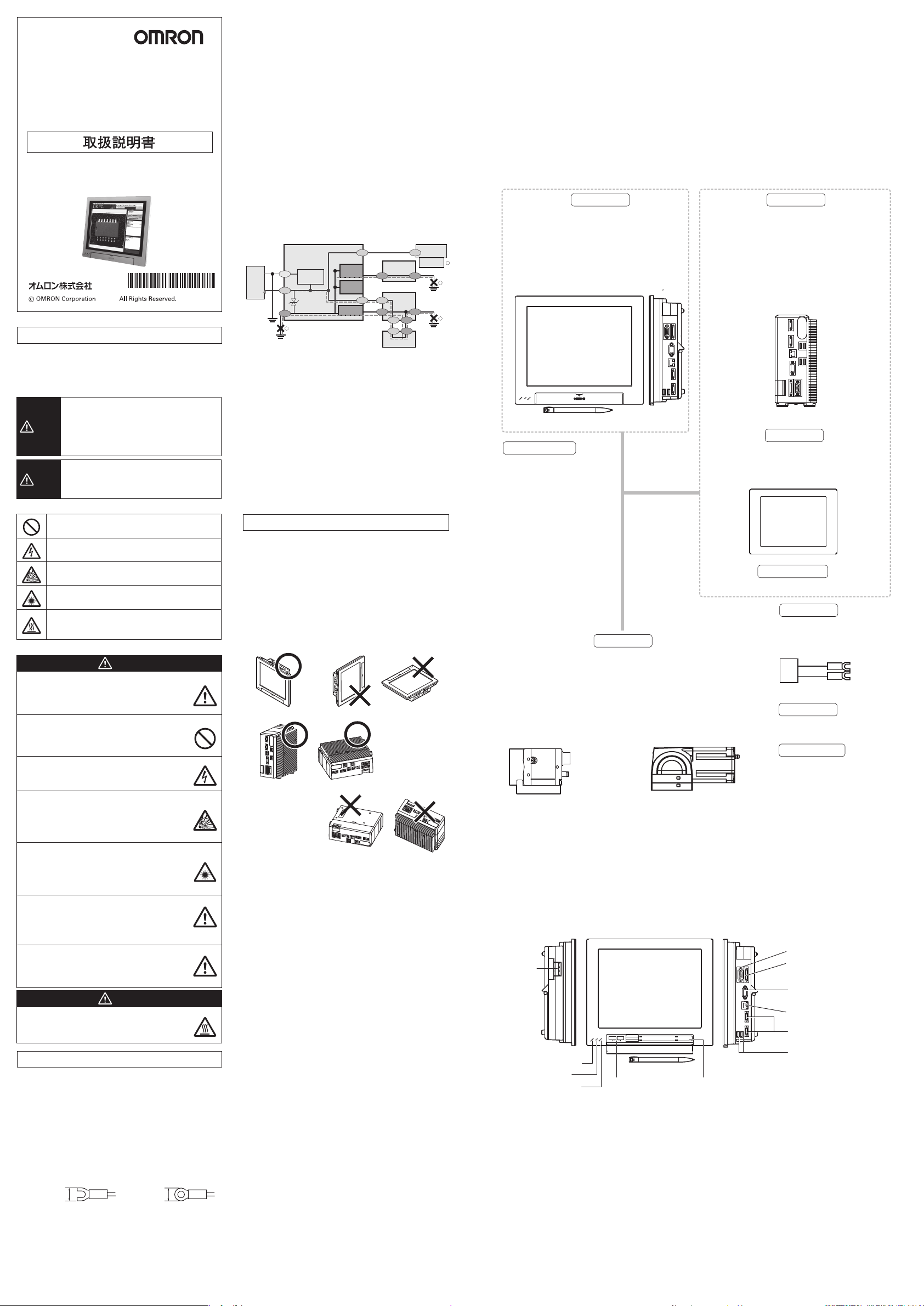
●接地について
・コントローラの電源回路は内部回路と絶縁されていません。
・24VDC電源のプラス(+)端子を接地する場合は、コントローラのFG
端子、PLCのFG端子、EtherCAT対向機のFG端子を接地しないでく
ださい。【①、②、③】
パソコンの外郭とSG(0V)がパソコン内部で接続されていますの
で、下図のような経路で電流が流れ焼損の原因になります。
・パソコンのようなSG(0V)とFGが短絡する経路が無い場合には、コン
トローラのFG端子を接地しても問題ありません。PLCについては、
ご使用のPLCの仕様をご確認の上、配線してください。
・コントローラに接続するカメラは必ず台座を使用して取り付けして
ください。【④】
カメラ本体の外郭はSG(0V)ですので、台座が無い場合には、SG(0V)
と短絡する恐れがあります。
・プラス(+)端子を接地する場合は、SG(0V)(例:カメラ本体、電源端
子)を指等で触れないでください。感電の恐れがあります。
・BOXタイプのコントローラ(形FZ4-(H)65□(-10)/形FZ4-(H)75□
(-10)/形FZ4-(H)115□(-10))を底面で取り付ける場合、底面が
SG(0V)に接続されていますので、お客様装置のFGと短絡します。
絶縁スペーサを用意しておりますので弊社営業担当にお問い合わせ
ください。
コントローラ
24V
電源
●その他
・専用のカメラ、ケーブル以外を使用しないでください。専用品以外
では、誤動作、破損の恐れがあります。
・カメラやケーブル類を着脱するときは、必ずセンサコントローラの
電源を切ってください。
・この製品を分解したり、修理、改造しないでください。
・万一、異常を感じたときには、すぐに使用を中止し、電源を切った
上で当社支店・営業所までご相談ください。
・通電中や電源を切った直後は、センサコントローラやカメラケース
が熱くなっており、ケースに触らないでください。
・廃棄するときは、産業廃棄物として処理してください。
電源回路
0V
SG
FG
FG
1
SG:
Signal Ground
FG:
Frame Ground
SG(0V)
SG SG
EtherCAT
コネクタ外郭
パラレルI/O
コネクタ外郭
SG
RS-232C
RS-232C
コネクタ外郭
カメラケーブル
SG(0V)
EtherCAT
対向機
FG FG
SG
FG FG
SG
RS-232C
SG FG
パソコン
PLC
FG
外郭
カメラ
取付台座
(絶縁)
3
2
使用上の注意
●設置場所、保管場所について
次のような場所に設置、保管してください。
・周囲温度が0〜+50℃(保管時−20〜+65℃)の場所
・温度が急激に変化しない場所(結露しない場所)
・相対湿度が35〜85%RHの場所
・腐食性ガス、可燃性ガスのない場所
・塵埃、塩分、鉄粉のない場所
・振動や衝撃のない場所
・直射日光があたらない場所
・水・油・化学薬品の飛沫がない場所
●設置方向
放熱を良くするため、下記の方向のみで設置してください。
●液晶一体タイプ
●BOXタイプ
●周囲温度
・通風を良くするため、コントローラの上下は他の機器と50mm以上
の間隔をあけて下さい。左右は30mm、他の機器またはコントロー
ラと10mm以上隙間をあけて接地してください。ただし、上下左右
に隣接するものが発熱体でない場合、上部は同じく50mm以上、下
部および左右は取付け方法に従って設置してください。
・ヒータ、トランスや大容量の抵抗など、発熱量の高い機器の真上に
は取付けないでください。
・使用周囲温度は50℃以下にしてください。
・使用周囲温度が50℃に近い場合は、強制ファンやクーラーを設置し
て、常時50℃を超えないようにしてください。
●耐ノイズ性
・高圧機器の設置されている盤内には取付けないでください。
・動力線からは、200mm以上離してください。
●構成品の設置や取扱いについて
・信号線に触れる
端子部分やコネクタ内部の信号線に触れる場合は、静電気による破
損を防ぐため、リストストラップなどを使用して帯電防止措置を行
ってください。
・USBメモリの取扱い
USBメモリを取外す場合は、データの読み/書き中でないことを確認
して取外してください。データの読み/書き中はUSBメモリ本体の
LEDが点滅しますので、点灯状態になったことを確認して取外して
ください。
・電源を切る
処理を実行中であることを示すメッセージが画面に表示されている
ときは、電源をOFFしないでください。メモリ上のデータが破損
し、次に起動したとき正常に動作しません。
・RESET信号について
電源をON直後にRESET入力をしないでください。起動タイミング
を同期させるためなどにRESET入力を使用する場合は、コントロー
ラの電源をONにした後、15秒以上おいてからRESET信号をONにし
てください。
・液晶一体タイプ(形FZ4-(H)60□(-10)/形FZ4-(H)70□(-10)/形
FZ4-(H)110□(-10))に使用している液晶ディスプレイは精密な技術
で作られておりますが、ごくわずかに画素欠陥がある場合がありま
す。これは液晶パネルの構造によるもので故障ではありません。
●メンテナンスについて
・お手入れをするときは、電源を切って、安全を確認してから行って
ください。
・レンズの汚れは、レンズ専用の布、またはエアブラシを使用して取
除いてください。
・装置の汚れは柔らかい布で軽く拭き取ってください。
CCDの汚れは、エアブラシを使用して取除いてください。
・
・シンナー、ベンジンは使用しないてください。
●上位機器との通信について
本製品の起動を確認後、上位機器との通信を行ってください。ま
た、本製品の起動時は上位インターフェースから不定な信号が出る
可能性がありますので、初期動作時はご使用機器の受信バッファを
クリアするなどの処置を実施してください。
このような方向で設置しないでください
通風経路を確保するため、
側面(下になる面)に
脚 を 取 付 け てくだ さい 。
このような方向で設置しないでください
■パッケージ内容の確認
・コントローラ・・・・・・・・・・・・1台
・取扱説明書(和英)・・・・・・・・・1式
・取付金具(パネルマウント用)・・・・6個 ※液晶一体タイプのみ付属しています。
・タッチペン・・・・・・・・・・・・・1本 ※液晶一体タイプのみ、コントローラ内部に収納されています。
■米国カリフォルニア州過塩素酸塩規制について
この製品はカリフォルニア州法で規制されている過塩素酸塩を含むリチウムバッテリを内蔵しておりますので、この州法へ
の対応をしてください。詳しくは、下記URLをご覧ください。
www.dtsc.ca.gov/hazardouswaste/perchlorate
■基本構成
*印は専用品です。これら以外は使用できません。
*
画像の確認や条件設定用メニューを表示するために使用し
ます。また、設定条件に従った画像処理を行い、計測結果を
出力する部 分 です 。
液晶一体タイプ
形FZ4-(H)60□(-10)
4
形FZ4-(H)70□(-10)
形FZ4-(H)110□(-10)
*
カメラ ケ ー ブ ル
コ ント ロ ー ラ
正面
タッチペン(付属品)
BOXタイプ
形FZ4-(H)65□(-10)
形FZ4-(H)75□(-10)
形FZ4-(H)115□(-10)
右側面
カメラ ケ ーブ ル
形FZ-VS3(2m、3m、5m、10m)
耐屈曲カメラケーブル
形FZ-VSB3(2m、3m、5m、10m)
ラ イト ア ン グ ル カ メ ラ ケ ー ブ ル
形FZ-VSL3(2m、3m、5m、10m)
耐屈曲ライトアングルカメラケーブル
形FZ-VSLB3(2m、3m、5m、10m)
長距離カメラケーブル
形FZ-VS4(15m)
長距離ライトアングルカメラケーブル
形FZ-VSL4(15m)
*
コ ント ロ ー ラ
設定条件に従った画像処理を行い 、
計測結果を出力する部分です。
*
液 晶モニタ
画像の確認や条件設定用メニュ ー
を表示するために使用します。
形FZ-M08(8.4インチ)
*
モニタケ ーブ ル
形FZ-VM(2m、5m)
電源装置
*
カメラ
計測物を画像として取込む部分です。
単 体 カメラ
形FZ-SC/形FZ-S/形FZ-SC2M
形FZ-S2M/
形FZ-SC5M2/形FZ-S5M2
形FZ-SFC/形FZ-SF/形FZ-SPC
形FZ-SP/形FZ-SHC/形FZ-SH
インテリジェントコン パクトカメラ
形FZ-SQ010F/形FZ-SQ050F
形FZ-SQ100F/形FZ-SQ100N
推奨品
オムロン(株)製
形S8VS-12024
周辺機器
*
USBメモリ
FZ-MEM2G/形FZ-MEM8G
入 力 デ バ イス
マ ウ ス 、ト ラ ッ ク ボ ー ル
(USBインタフェースの市販品)
※形FZ-SC5M2/形FZ-S5M2は、形FZ4-6□□/形FZ4-H6□□/形FZ4-7□□/
形FZ4-H7□□/形FZ4-11□□/形FZ4-H11□□に接続可能です。
※インテリジェントコンパクトカメラは、形FZ4-6□□/形FZ4-H6□□/形FZ4-7□□/形FZ4-H7□□/形FZ4-11□□
/形FZ4-H11□□に接続可能です。
■各部の名称とはたらき
●液晶一体タイプ 形FZ4-(H)60□(-10)/形FZ4-(H)70□(-10)/形FZ4-(H)110□(-10)
⑩
USBコネクタ
正面
⑫
タッチペン(収納)
⑨
RS-232C/422接 続コネクタ
④
入 出 力コネクタ
(制御線、データ線)
⑧
モニタ 接 続 コネクタ
( ア ナ ログ RGB)
⑪
イ ー サ ネ ット 接 続 コ ネ ク タ
⑤
カメラ コ ネクタ
⑩
USBコネクタ
⑥⑦
電 源・
接地端子
①
②
③
左側面 右側面
POWER LED
RUN LED
ERROR LED
Page 2
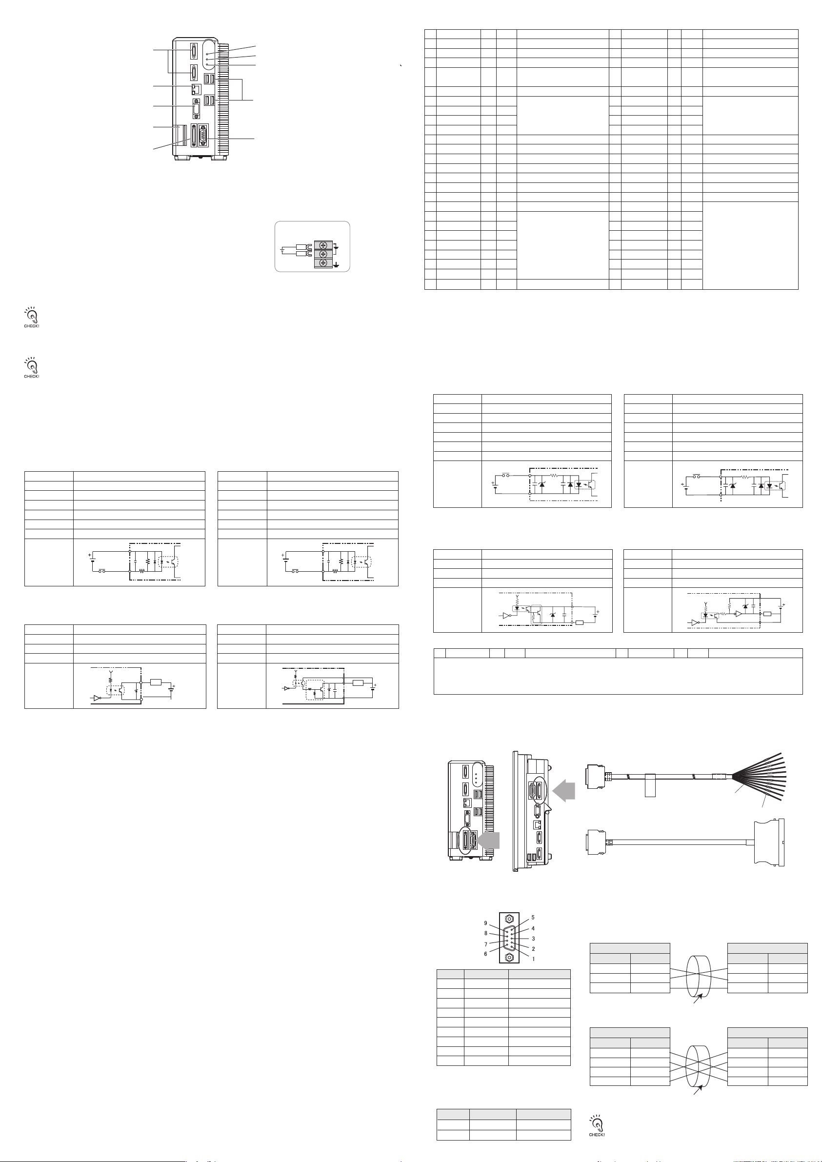
●BOXタイプ 形FZ4-(H)65□(-10)/形FZ4-(H)75□(-10)/形FZ4-(H)115□(-10)
①
⑤
カメラ コ ネクタ
イ ー サ ネ ット 接 続 コ ネ ク タ
⑪
モ ニ タ 接 続 コ ネ ク タ( ア ナ ロ グ RGB)
⑧
電源・接地端子
⑥⑦
④
入出力コネクタ(制御線、データ線)
POWER LED
RUN LED
②
ERROR LED
③
⑩
USBコネクタ
⑨
RS-232C/422接 続コネクタ
① 通電中、点灯します。
② 計測モードに入っている間、点灯します。
③ 異常が発生したときに点灯します。
④ 同期センサ、プログラマブルコントローラなどの外部装置と接続します。
⑤ カメラを 接 続します 。
⑥ DC電源を接続します。他の機器とは独立して配線してください。配線後は、
端子カバー(透明)を元の場所に取付けてください。
⑦ 接地線を配線します。必ずコントローラ単独で配線してください。
⑧ モニ タを 接 続しま す 。
電源の配線
24VDC
+
-
⑨ パソコン、プログラマブルコントローラなどの外部装置と接続します。
⑩ トラックボール、マウス、USBメモリと接続します。計4ポートありますが、どのポートを使用しても問題ありません。
ただし、USBメモリは隣り合ったポートに接続しないでください。USBメモリ同士が接触し誤動作や破損の恐れがあります。
・USBコネクタの接続対象は右記のとおりです。 ・市販のトラックボール、マウス ・USBメモリ
・計測稼動中にUSB機器を抜き差ししないでください。計測時間に影響が出る可能性があります。
⑪ パソコンと接 続します 。
⑫ 操作用のタッチペンが収納されています。(液晶一体タイプのみ)
・タッチペンは必 ずコントローラに 向かってペン先 が 右 向きなるよう収納してください。
・取出す時はペンの左側(持ち手)を奥へ押してください。ペンの右側(ペン先)が前に飛出しますので、摘んで取出してください。
■ パラレ ル インタフェース
NPN 入 出 力 タイプ 形FZ4-(H)6□0(-10)/形FZ4-(H)7□0(-10)
形FZ4-(H)11□0(-10
●内部仕様
対象信号/RESET、DI0〜DI7、DSA0、DSA1
【入力】
入力電圧
ON電流 ※1
ON電圧 ※1
OFF電流 ※2
OFF電圧 ※2
ONディレ ー
OFFディレ ー
内部回路図
※1 ON電流/ON電圧 OFF→ON状態にさせる電流値または電圧値のことです。 ON電 圧の値は、COM INと各入力端子間の電位差となります。
※2 OFF電流/OFF電圧 ON→OFF状態にさせる電流値または電圧値のことです。 OFF電 圧の値は、COM INと各入力端子間の電位差となります。
【出力】
出力電圧
負荷電流
ON残留電圧
OFF漏れ電流
内部回路図
対象信号/
DC12〜24V ±10%
最小5mA
最小8.8V
最大0.5mA
最大1.1V
5ms以下
0.7ms以下
COM IN
各入力端子
BUSY0、RUN/BUSY1、OR0~1、GATE0~1、
ERROR、DO0~15、READY0~1
DC12〜24V ±10%
45mA以下
2V以下
0.2mA以下
各出力端子
負荷
COM OUT
【入力】
【出力】
対象信号/STEP0/ENCTRIGZ0、STEP1/ENCTRIGZ1、
入力電圧
ON電流 ※1
ON電圧 ※1
OFF電流 ※2
OFF電圧 ※2
ONディレ ー
OFFディレ ー
内部回路図
対象信号/STGOUT0〜1
STGOUT0、1を使用時はCOMIN端子を接続してください。
出力電圧
負荷電流
ON残留電圧
OFF漏れ電流
内部回路図
ENCTRIGA0〜1、ENCTRIGB0〜1
DC12〜24V ±10%
最小5mA
最小8.8V
最大0.5mA
最大0.8V
0.1ms以下
0.1ms以下
COM IN
各入力端子
DC12〜24V ±10%
45mA以下
2V以下
0.2mA以下
COM IN
負荷
各出力端子
COM OUT
● 入 出 力コネクタ
No. 線色
A1
COMIN
ENCTRIGA1(※2)
A2
ENCTRIGB1(※2)
A3
STEP1(※2)/
A4
ENCTRIGZ1(※2)
DSA1(※2)
A5
DI1
A6
DI3
A7
DI5
A8
DI7
A9
STGOUT1
A10
空き
A11
ERROR
A12
COMOUT1
A13
GATE1(※2)
A14
OR1(※2)
A15
READY1(※2)
A16
COMOUT2
A17
DO1
A18
DO3
A19
DO5
A20
DO7
A21
DO9
A22
DO11
A23
DO13
A24
COMOUT3
A25
・出力用コモン端子の対応
COMOUT1:STGOUT0〜1、RUN/BUSY1、ERROR、BUSY0、OR0〜1、GATE0〜1 COMOUT2:READY0〜1、DO0〜7 COMOUT3:DO8〜15
※1コントローラにストロボ装置を接続したい場合に使用する信号です。
※2 2ラインランダムトリガモード 時 の み 使 用できます 。
マーク(赤)
■
橙
灰
白
黄
入力信号用コモン
■
エンコーダトリガ入力(A相)
■
エンコーダトリガ入力(B相)
■
計測トリガ入力/
エンコーダトリガ入力(Z相)
■
桃
橙
灰
白
黄
桃
橙
灰
白
黄
桃
橙
灰
白
黄
桃
橙
灰
白
黄
桃
データ送信要求信号
■■
コ マ ンド 入 力
■■
■■
■■
■■
ストロボトリガ出力(※1)
■■■
(接続しないでください)
■■■
エラー発生時にON
■■■
制御信号用コモン
■■■
設定した出力時間中ON
■■■
総合判定結果
■■■■
画像入力が許可されるときON
■■■■
出力信号用コモン
■■■■
データ 出 力
■■■■
■■■■
■■■■■■
■■■■■■
■■■■■■
■■■■■■
■■■■■■
出力信号用コモン
役割信号名
No. 線色
RESET
B1
ENCTRIGA0
B2
ENCTRIGB0
B3
STEP/
B4
橙
灰
白
黄
ENCTRIGZ0
DSA0
B5
DI0
B6
DI2
B7
DI4
B8
DI6
B9
STGOUT0
B10
空き
B11
RUN/BUSY1(※2)
B12
BUSY0
B13
GATE0
B14
OR0
B15
READY0
B16
DO0
B17
DO2
B18
DO4
B19
DO6
B20
DO8
B21
DO10
B22
DO12
B23
DO14
B24
DO15
B25
桃
橙
灰
白
黄
桃
橙
灰
白
黄
桃
橙
灰
白
黄
桃
橙
灰
白
黄
桃
マーク(黒)
■
コントローラ再起動
■
エンコーダトリガ入力(A相)
■
エンコーダトリガ入力(B相)
■
計測トリガ入力/
役割信号名
エンコーダトリガ入力(Z相)
■
データ送信要求信号
■■
コ マ ンド 入 力
■■
■■
■■
■■
ストロボトリガ出力(※1)
■■■
(接続しないでください)
■■■
計測モード中ON/処理実行中にON
■■■
処理実行中にON
■■■
設定した出力時間中ON
■■■
総合判定結果
■■■■
画像入力が許可されるときON
■■■■
データ 出 力
■■■■
■■■■
■■■■
■■■■■■
■■■■■■
■■■■■■
■■■■■■
■■■■■■
PNP入出力タイプ 形FZ4-(H)6□5(-10)/形FZ4-(H)7□5(-10)
形FZ4-(H)11□5(-10)
●内部仕様
対象信号/RESET、DI0〜DI7、DSA0、DSA1
【入力】
入力電圧
ON電流 ※1
ON電圧 ※1
OFF電流 ※2
OFF電圧 ※2
ONディレ ー
OFFディレ ー
内部回路図
※1 ON電流/ON電圧 OFF→ON状態にさせる電流値または電圧値のことです。 ON電圧の値は、COM INと各入力端子間の電位差となります。
※2 OFF電流/OFF電圧 ON→OFF状態にさせる電流値または電圧値のことです。 OFF電圧の値は、COM INと各入力端子間の電位差となります。
【出力】
出力電圧
負荷電流
ON残留電圧
OFF漏れ電流
対象信号/
DC12〜24V ±10%
最小5mA
最小8.8V
最大0.5mA
最大1.1V
5ms以下
0.7ms以下
各入力端子
COM IN
BUSY0、RUN/BUSY1、OR0〜1、GATE0〜1、
ERROR、DO0〜15、READY0〜1
DC12〜24V ±10%
45mA以下
2V以下
0.2mA以下
内部回路図
COM OUT
負荷
各出力端子
● 入 出 力 コネクタ
No. 線色
マーク(赤)
役割信号名
対象信号/STEP0/ENCTRIGZ0、STEP1/ENCTRIGZ1、
【入力】
入力電圧
ON電流 ※1
ON電圧 ※1
OFF電流 ※2
OFF電圧 ※2
ONディレ ー
OFFディレ ー
内部回路図
対象信号/STGOUT0〜1
【出力】
STGOUT0、1を使用時はCOMIN端子を接続してください。
出力電圧
負荷電流
ON残留電圧
OFF漏れ電流
ENCTRIGA0〜1、ENCTRIGB0〜1
DC12〜24V ±10%
最小5mA
最小8.8V
最大0.5mA
最大0.8V
0.1ms以下
0.1ms以下
各入力端子
COM IN
DC12〜24V ±10%
45mA以下
2V以下
0.2mA以下
内部回路図
No. 線色
マーク(黒)
役割信号名
COM OUT
各出力端子
負荷
COM IN
入出力コネクタの配線はNPNタイプと同じです。
●コネクタ
パラレ ル I/Oケーブ ル 形 FZ-VP、FZ-VPX (別売)を接続します。
BOXタイプ
液晶一体タイプ
■ シリア ル インタフェー ス
●コネクタ
ピン No.
適 合 するコネクタをご用 意ください。
・推奨品
プラグ
フ ード
1
2
3
4
5
6
7
8
9
信号名
SDB(+)
SD/SDA(-)
RD/RDA(-)
RDB(+)
NC
NC
NC
NC
GND
役割
RS-422用
RS-232C用/RS-422用
RS-232C用/RS-422用
RS-422用
無接続
無接続
無接続
無接続
信号用接地
メーカ ー 形式
オムロン(株)
オムロン(株)
形XM3A-0921
形XM2S-0911
形FZ-VP(2m、5m)
線色
No.
マーク
形FZ-VPX(2m、5m)
●配線
ケーブル長は、15m以 下 にし てください 。
・RS-232C
コ ント ロ ー ラ
信号名
SD
RD
GND
シ ー ルドさ れ た ケ ー ブ ル を 使 用し てください 。
ピン No.
2
3
9
・RS-422
コ ント ロ ー ラ
信号名
SDB(+)
SDA(-)
RDA(-)
RDB(+)
シ ー ルドさ れ た ケ ー ブ ル を 使 用し てください 。
ピン番号は、接続する外部装置の種類や機種によって異なります。お手持 ち
のプログラマブルコントローラやパソコンの取扱説明書を確認してください。
ピン No.
1
2
3
4
接続する外部装置
ピン No.
*
*
*
RS/CS制 御 はできませ ん 。
接続する外部装置
ピン No.
*
*
*
*
信号名
SD
RD
GND
信号名
SDA(-)
SDB(+)
RDB(+)
RDA(-)
Page 3

●接続方法
コネクタの向きを合わせ、まっすぐに差込み、
コネクタの 両 端 の ねじで 固 定してください 。
電源を切った状態でケーブルを着脱してください。
周辺機器の破損の原因になります。
液晶一体タイプ
BOXタイプ
■取付け
●液晶一体タイプ
・パ ネ ル 取 付 け
①パネルに取付け用の穴をあけます。
パネルの板厚範囲:1.6〜4.8mm
パ ネ ル の 材 質: 金属製(鉄、アルミ、
またはステンレス )
1
+
0
247
297
1
+
0
②液晶一体タイプコントローラを
パネル前面から挿入します。
■コントローラ外形寸法
●液晶一体タイプ
カメラ 2ch タイプ
形 FZ4-(H)60□
形 FZ4-(H)70□
形 FZ4-(H)110□
260
●BOXタイプ
4-M4 深さ6
カメラ 4ch タイプ
形 FZ4-(H)60□-10
形 FZ4-(H)70□-10
形 FZ4-(H)110□-10
308
形FZ4-(H)65□(-10)/形FZ4-(H)75□(-10)/形FZ4-(H)115□(-10)
90
17 80
190
11 126
8
4-M4 深さ6
13
64
26
A
A=104(4カメラ タイプ )
83(2カメラタ イプ )
165
( )
68
( )
100
39
4-φ 20
(単位:mm)
※ バ リなきこと
上面
③付属の取付金具で、液晶一体タイプ
コントローラとパネルを固定します。
締付トルク:0.5〜0.6Nm
下面
4-M
120 120
20
深さ6
3
7
( )
246
110
68
7
6
130
296
20
120 120
+
-
( )
(単位mm)
( )28.412.8 10
・卓上コントローラスタンド(別売)取付け
別売りの卓上コントローラスタ
ンド 形 FZ-DSを背面に装着す
ることにより、卓 上に据え置き
することが できます 。
※詳しくは卓上コントローラスタンドの
取扱説明書をご参照ください。
・VESAアタッチメント(別売)取付け
別 売りの VESA ア タ ッ チ メ ント
形FZ-VESAを背面に装着す
ることにより VESA 規格のマ
ウ ント が で き ま す 。
※ 詳しくは VESAア タ ッ チ メント の 取
扱説明書をご参照ください。
●BOXタイプ
33
163.5
( )
6
・側面取付け ・底面取付け
(17)
126±0.25
(11)
80±0.25
※底面で固定する場合は通風経路を確保するため、
脚を 外さ ず 共 締 めしてくださ い 。
4-M4 深さ6
4-M4 深さ6
(13)
64±0.25
(26)
100±0.25
4-φ 20
( )
39
(18)
54±0.25
■ コ ント ロ ー ラ の 仕 様
操作
液晶一体タイプ:タッチペン、マウスなどによる操作
BOXタイプ:マウスなどによる操作
RS-232C/422:1CH
Ethernet100BASE-TX/10BASE-T
Ethernetポート使用
(単位mm)
シリア ル 通 信
ネ ット ワ ー ク 通 信
EtherNet/IP通信
伝送速度:100Mbps(100BASE-TX)
パラレル 入 出 力
入力17点(RESET、STEP0/ENCTRIGZ0、STEP1/ENCTRIGZ1、DSA0〜1、ENCTRIGA0〜1、ENCTRIGB0〜1、DI0〜7)
出力29点(RUN/BUSY1、BUSY0、GATE0〜1、OR0〜1、READY0〜1、ERROR、STGOUT0〜3、DO0〜15)
モニタI/F
液晶一体タイプ:コントローラと一体型12.1インチTFTカラー液晶(解像度XGA1024×768)
BOXタイプ:アナログRGBビデオ出力1ch(解像度XGA1024×768)
( )
68
80 17
4-M4 深さ6
USBI/F
電源電圧
消費電流
(DC24.0V使用時)
4CH(USB1.1/2.0準拠)
DC24V(DC20.4〜26.4V)
形FZ-S□/形「FZ-S□2M/形FZ-SF□/形FZ-SP□/形FZ-SH□接続時:
カメラ2chタイプ:約3.7A以下 カメラ4chタイプ:約4.9A以下
形FZ-SQ□□□□接続時:
カメラ2chタイプ:約5.0A以下 カメラ4chタイプ:約7.5A以下
絶縁抵抗
耐電圧
漏れ電流
耐ノイズ 性
耐振動
33
( )
15.45
( )
126
+
-
11
6.8
11.5
耐衝撃
1854
周囲温度範囲
DC外部端子一括とアース端子間:20MΩ以上(DC100Vメガにて ただし、内蔵サージアブソーバを外した場合
DC外部端子一括とアース端子間:AC1000V 50/60Hz
10mA以下
2kV、パルス立上がり:5ns パルス幅:50ns
バースト継続時間:15ms 周期:300ms
10〜150Hz 片振幅0.1mm(加速度最大15m/s
2
150m/s
6方向各3回
2
)3方向各8分10回
動作時: 0〜+50℃
周囲温度を設定可能、設定に応じて冷却ファンの回転速度を切替
)
0〜+45℃:低速回転 0〜+50℃:高速回転
保存時: −20〜+65℃(ただし氷結・結露しないこと)
周囲湿度範囲
周囲雰囲気
接 地
保護構造
ケースの材 質
質 量
動作時・保存時:各35〜85%RH(ただし結露しないこと)
腐食性ガスのないこと
D種接地(接地抵抗100Ω以下)*従来の第三種接地
IEC60529規格IP20
ABS
液晶一体タイプ(カメラ2chタイプ:約3.2kg カメラ4chタイプ:約3.4kg)
BOXタイプ:(カメラ2chタイプ:約1.8kg カメラ4chタイプ:約約1.9kg)
ご承諾事項
当社商品は、一般工業製品向けの汎用品として設計製造されています。従いまして、次に
掲げる用途での使用を意図しておらず、お客様が当社商品をこれらの用途に使用される際
には、当社は当社商品に対して一切保証をいたしません。ただし、次に掲げる用途であって
も当社の意図した特別な商品用途の場合や特別の合意がある場合は除きます。
(a)高い安全性が必要とされる用途(例:原子力制御設備、燃焼設備、航空・宇宙設備、鉄
道設備、昇降設備、娯楽設備、医用機器、安全装置、その他生命・身体に危険が及び
うる用途)
(b)高い信頼性が必要な用途(例:ガス・水道・電気等の供給システム、24時間連続運転
システム、決済システムほか権利・財産を取扱う用途など)
(c)厳しい条件または環境での用途(例:屋外に設置する設備、化学的汚染を被る設備、
電磁的妨害を被る設備、振動・衝撃を受ける設備など)
(d)カタログ等に記載のない条件や環境での用途
*(a)から(d)に記載されている他、本カタログ等記載の商品は自動車(二輪車含む。以下同
じ)向けではありません。自動車に搭載する用途には利用しないで下さい。自動車搭載
用商品については当社営業担当者にご相談ください。
*上記は適合用途の条件の一部です。当社のベスト、総合カタログ、データシート等最新版
のカタログ、マニュアルに記載の保証・免責事項の内容をよく読んでご使用ください。
●製品に関するお問い合わせ先
お客様相談室
インダストリアルオートメーションビジネスカンパニ ー
クイック オムロン
0120-919-066
携帯電話・PHS・IP電話などではご利用いただけませんので、下記の電話番号へおかけください。
電話
055-982-5015
■営業時間:8:00〜21:00 ■営業日:365日
●FAXやWebページでもお問い合わせいただけます。
FAX055-982-5051/www.fa.omron.co.jp
●その他のお問い合わせ
納期・価格・サンプル・仕様書は貴社のお取引先、または貴社
担当オムロン販売員にご相談ください。
オムロン制御機器販売店やオムロン販売拠点は、Webページで
ご案内しています。
v
A
2014年7月
(通話料がかかります)
Page 4

FZ4-(H)6□□(-10)
Model
FZ4-(H)7□□(-10)
FZ4-(H)11□□(-10)
Vision Sensor
INSTRUCTION SHEET
Thank you for selecting OMRON product. This sheet
primarily describes precautions required in installing and
operating the product.
Before operating the product, read the sheet thoroughly
to acquire sufficient knowledge of the product. For your
convenience, keep the sheet at your disposal.
TRACEABILITY INFORMATION:
Importer in EU:
Omron Europe B.V.
Wegalaan 67-69
2132 JD Hoofddorp,
The Netherlands
The following notice applies only to products that carry the CE mark:
Notice:
This is a class A product. In residential areas it may cause radio
interference, in which case the user may be required to take adequate
measures to reduce interference.
Manufacturer:
Omron Corporation,
Shiokoji Horikawa, Shimogyo-ku,
Kyoto 600-8530 JAPAN
2013
●Ground
・The controller power circuit is not insulated from its internal circuit.
・When grounding the positive terminal of the 24 V DC power supply,
do not ground the controller s FG terminal, the PLC s FG terminal, or
EtherCAT facing component s FG terminal. 【①,②,③】
Since the PC s shell and the SG (0V) are connected inside the PC,
current would run through the route shown in the figure below and
cause burnout.
・As in the case with a PC, you can safely ground the controller s FG
terminal without a problem when there is no possibility that the SG
(0V) and the FG will short-circuit. For information about the PLC
wiring, check the specifications of your PLC before wiring.
・Be sure to use a pedestal when connecting a camera to the
controller.【④】
As the shell of the camera is the SG (0V), it can cause
short-circuiting between the SG (0V) and the FG if a pedestal is not
used.
・To avoid receiving an electric shock when grounding
a positive terminal, do not touch the SG (0V)
(camera, power supply terminal).
・When mounting a box-shaped controller (FZ4-(H)65□
(-10)/FZ4-(H)75□(-10)/FZ4-(H)115□(-10)) at its base, it will
short-circuit to the FG ofyour device since the bottom surface is
connected to the SG (0V). In order to avoid this, we provide
insulating spacers. Please consult your OMRON representative for
information.
Camera cable
SG SG
EtherCAT
connector's
shell
Parallel I/O
connector
’
s
shell
SG
RS-232C
RS-232C
connector’s shell
SG(0V)
EtherCAT
facing component
FG FG
SG
FG FG
SG
SG FG
PLC
FG
Camera
Mounting spacer
(insulator)
Shell
Power
supply
Controller
24V
SG
FG
1
Power supply
circuit
0V
FG
SG:
Signal Ground
FG:
Frame Ground
SG(0V)
■Confirming Package Contents
・Controller・・・・・・・・・・・・・・・・Qty.: 1
・Instruction Manual
・Mounting bracket (for panel)・・・・・・・・Qty.: 6 *Supplied with the LCD integrated type onl
・Touch pen・・・・・・・・・・・・・・・Qty.: 1 *Supplied with the LCD integrated type only
■U.S. California Notice:
This product contains a lithium battery for which the following notice applies :Perchlorate Material - special handling may apply.
See www.dtsc.ca.gov/hazardouswaste/perchlorate
■Basic Configuration
* Items indicated with an asterisk are dedicated items, and cannot be substituted.
Use the monitor to check images and display the
condition-setting menus. The Controller performs
the image processing specified by the user settings
and outputs the measurement results.
LCD integrated type
4
3
2
FZ4-(H)60□(-10)
FZ4-(H)70□(-10)
FZ4-(H)110□(-10)
(Japanese and English)・・・Qty.: 1
*
Controller
Front view
Right-side view
(provided inside the controller).
*
Controller
The Controller performs the image
processing specified by the user settings
and outputs the measurement results.
Box type
FZ4-(H)65□(-10)
FZ4-(H)75□(-10)
FZ4-(H)115□(-10)
Meanings of Signal Words
●
Symbols and the meanings for safety precautions
described in this manual.
In order for the product to be used safely, the following indications are
used in this book to draw your attention to the cautions. The cautions
with the indications describe the important contents for safety.
Indicates a potentially hazardous
situation which, if not avoided, will
WARNING
CAUTION
result in minor or moderate injury, or
may result in serious injury or death.
Additionally there may be significant
property damage.
Indicates a potentially hazardous
situation which, if not avoided, may
result in minor or moderate injury or in
property damage.
Meanings of Alert Symbols
The following alert symbols are used in this manual.
Indicates general prohibitions for which there is
no specific symbol.
Indicates the possibility of electric shock under
specific conditions.
Indicates the possibility of explosion under
specific conditions.
Indicates the possibility of laser radiation.
Indicates the possibility of injury by high
temperature under specific conditions.
Alert statements in this Manual
The following alert statements apply to the products in this
manual. Each alert statement also appears at the locations
needed in this manual to attract your attention.
WARNING
This product must be used according to the
instruction manual. Failure to observe this may
result in impairment of functions and
performance of the product.
This product is not designed or rated for
ensuring safety of persons. Do not use it for
such purposes.
Never connect the AC power supply with this
product. When the AC power supply is
connected, it causes the electric shock and a fire.
A lithium battery is built into the Controller and
may occasionally combust, explode, or burn if
not treated properly. Dispose of the Controller as
industrial waste, and never disassemble, apply
pressure that would deform, heat to 100℃ or
higher, or incinerate the Controller.
Since camera that can be connected with this
product emits a visible light that may have an
adverse effect on the eyes, do not stare directly
into the light emitted from the LED. If a specular
object is used, take care not to allow reflected
light enter your eyes.
Please take external safety measures so that the system
as a whole should be on the safe side even if a failure of
a sensor controller or an error due to an external factor
occurred.An abnormal operation may result in a serious
accident.
Please take fail-safe measures on your side in
preparation for an abnormal signal due to signal
conductor disconnection and/or momentary power
interruption.An abnormal operation may result in a
serious accident.
CAUTION
Danger of burns. Do not touch the case while the
LED is ON or just after power is turned OFF,
since it remains extremely hot.
Precautions for Safe Use
●Installation Environment
• Do not use the product in areas where flammable or explosive
gases are present.
• Install the product so that air can flow freely through its cooling
vents.
• Do not install the product close to high-voltage devices and power
devices in order to secure the safety of operation and
maintenance.
• Make sure to tighten all installation screws securely.
●Power Supply and Wiring
• Make sure to use the product with the power supply voltage
specified by this manual.
• Use the cables and crimping terminals with the specified
dimensions. Do not directly connect an electric wire to the terminal
block that is simply twisted.
−Applicable Wire Size: 1.31 to 2.63 mm2
−Terminal Screw: M4
−Crimping Terminal
8.5mm max. 8.5mm max.
• Keep the power supply wires as short as possible (Max.10m).
• Use a DC power supply with safety measures against high-voltage
spikes(safety extra low-voltage circuits on the secondary side).
・Ground the product's ground terminal to less than 100Ω.
・Use a grounding point that is as close as possible and keep the
ground wire as short as possible.
・Wire the Controller to the ground with a separate ground wire. To
avoid grounding problems, do not share the ground wire with any
other devices or wire the ground to the building's steel framing.
• Do the following confirmations again before turning on the
power supply.
- Is the voltage of the power supply correct? (24VDC)
- Is not the load of the output signal short-circuited?
- Is the load current of the output signal appropriate?
- Is not the mistake found in wiring?
●Other
• Use only the camera and cables designed specifically for the product.
Use of other products may result in malfunction or damage of the
product.
• Always turn OFF the Controller's power before connecting or
disconnecting a camera or cable. Connecting the cable with power
supplied may result in damage of the camera or peripheral devices.
• Do not attempt to dismantle, repair, or modify the product.
• Should you notice any abnormalities, immediately stop use, turn OFF
the power supply, and contact your OMRON representative.
•
Do not touch fluorescent or halogen lights while the power is ON or
immediately after the power is tumed OFF.
• Dispose of this product as industrial waste.
●Regulations of KC marking
A급 기기(업무용 방송통신기자재)
이 기기는 업무용(A급) 전자파적합기기로서 판매자
또는 사용자는 이 점을 주의하시기 바라며,가정외의
지역에서 사용하는 것을 목적으로 합니다.
Precautions for Correct Use
●InstallationandStorageSites
Installandstoretheproductinalocationthatmeets
thefollowingconditions:
•Surrounding temperature of 0 to +50°C(-20 to + 65°C in storage)
• No rapid changes in temperature (place where dew does not form)
• Relative humidity of between 35 to 85 %
• No presence of corrosive or flammable gases
• Place free of dust, salts and iron particles
• Place free of vibration and shock
• Place out of direct sunlight
• Place where it will not come into contact with water, oils or chemicals
●OrientationofProduct
To improve heat dissipation, install the product in the
following orientation only.
LCD integrated type
Box type
●Ambient Temperature
• Maintain a minimum clearance of 50 mm above and below the controller
to improve air circulation. A minimum clearance of 10 mm between
other devices must also be maintained on the right and left sides of the
product. However, if the adjacent devices do not generate heat, provide
at least 50 mm of clearance from the top of the Controller. For the
clearance at the bottom and sides, follow the mounting method.
• Do not install the product immediately above significant heat sources,
such as heaters, transformers, or large-capacity resistors.
• Do not let the ambient temperature exceed 50 °C (122 °F).
• Provide a forced-air fan cooling or air conditioning if the ambient
temperature is near 50 °C (122 °F) so that the ambient temperature
never exceeds 50 °C (122 °F).
●Noise Resistance
• Do not install the product in a cabinet containing high-voltage equipment.
• Do not install the product within 200 mm of power cables.
●Component Installation and Handling
• Touching Signal Lines
To prevent damage from static electricity, use a wrist strap or another
device for preventing electrostatic discharges when touching terminals or
signal lines in connectors.
• Handling a USB Memory
To remove a USB memory, make sure that data is not being read or
written to it.The LED on the USB memory flashes while data is being read
or written, so make sure that it is lit steadily before removing the memory.
• Turning OFF the Power
Do not turn OFF the power while a message is being displayed indicating
that processing is being performed. Data in memory will be corrupted, and
the product may not operate correctly the next time it is started.
• Using the RESET Signal
Do not use the RESET input immediately after power is turned ON. When
using the RESET input to synchronize startup timing, wait at least 15
second after the Controller’ s power supply is turned ON before turning
ON the RESET signal.
• The LCD panel used for the LCD-integrated type (FZ4-(H)60□
(-10)/FZ4-(H)70□(-10)/FZ4-(H)110□(-10)) has been made using
precision technology, and sometimes a few pixels are missing in the
panel. This is due to the structure of the LCD panel, and is not a
malfunction.
●Maintenance
• Turn OFF the power and take safety precautions before conducting
inspections. Electrical shock can result from attempting safety
inspections with the power turned ON.
• Clean the lens with a lens-cleaning cloth or air brush.
• Lightly wipe off dirt with a soft cloth.
• Dirt on the CCD must be removed using an air brush.
• Do not use thinners or benzene.
●Communication with High-order Device
After confirming that this product is started up, communicate with the
high-order device.
When this product has started up, an indefinite signal may be output from
the high-order interface.
To avoid this problem, clear the receiving buffer of your device at initial
operations.
Do not install in this orientation.
To reserve ventilation path,
the feet must be mounted
to the side panel that is
positioned at the base.
Do not install in this orientation.
Touch pen (standard accessory)
*
Camera cable
Use the monitor to check images
and display the condition-setting
menus.
Camera cable
FZ-VS3 (2 m, 3m, 5 m, 10 m)
Bend resistant camera cable
FZ-VSB3 (2 m, 3m, 5 m, 10 m)
Right-angle camera cable
FZ-VSL3 (2 m, 3m, 5 m, 10 m)
Bend resistant
Right-angle camera cable
FZ-VSLB3 (2 m, 3m, 5 m, 10 m)
Long-distance camera cable
FZ-VS4 (15m)
Long-distance Right-angle
camera cable
FZ-VSL4 (15m)
*
Camera
Detects workpieces as images.
Standalone camera
FZ-SC/FZ-S/FZ-SC2M
FZ-S2M
FZ-SC5M2/FZ-S5M2/FZ-SFC
Intelligent compact camera
FZ-SQ010F/FZ-SQ050F
FZ-SQ100F/FZ-SQ100N
FZ-SF/FZ-SPC/FZ-SP
FZ-SHC/FZ-SH
* FZ-SC5M2 and FZ-S5M2 can be connected to FZ4-6□□ and FZ4-H6□□/
FZ4-7□□/FZ4-H7□□/FZ4-11□□/FZ4-H11□□.
* Intelligent compact camera can be connected to FZ4-6□□ and FZ4-H6□□/FZ4-7□□/FZ4-H7□□/
FZ4-11□□/FZ4-H11□□.
■Component Names and Functions
LCD integrated type FZ4-(H)60□(-10)/FZ4-(H)70□(-10)/FZ4-(H)110□(-10)
Front view
10
USB connector•Touch pen (holder)
12
6
7
Power/
ground terminal
Left-side view Right-side view
1
POWER LED
2
RUN LED
3
ERROR LED
*
LCD monitor
FZ-M08 (8.4-inch)
*
Monitor cable
FZ-VM (2 m, 5 m)
Power Supply
Recommended Model
By OMRON Corporation
S8VS-12024
Peripheral Device
USB memory
FZ-MEM2G/FZ-MEM8G
Input Device
Mouse, track ball
(Commercially available
USB devices)
9
RS-232C/RS-422
connector
4
I/O connector
(control lines, data lines)
Monitor connector
8
(analog RGB)
11
Ethernet connector
Camera connector
5
10
USB connector
Page 5

Box type FZ4-(H)65□(-10)/FZ4-(H)75□(-10)/FZ4-(H)115□(-10)
•
1
5
Camera connector
11
Ethernet connector
8
Monitor connector (analog RGB)
6
7
Power/ground terminal
4
I/O connector (control lines, data lines)
1
Lit while power is ON.
2
Lit while the controller is in Run Mode.
3
Lit when an error has occurred.
4
Connect the controller to external devices such as a sync sensor and PLC.
5
Connect cameras.
6
Connect a DC power supply. Wire the power supply unit independently
of other devices. After wiring, replace the terminal cover.
7
Connect the ground wire. Make sure that the controller is grounded with a
separate ground wire.
8
Connect a monitor.
9
Connect an external device such as a personal computer or PLC.
10
Connect a track ball, mouse and USB memory. A total of four USB ports are provided and any of them can be
POWER LED
RUN LED
2
3
ERROR LED
10
USB connector
9
RS-232C/RS-422 connector
Power Supply Wiring
24VDC
+
–
used. However, when connecting two or more USB memories, do not connect them to adjacent ports. Doing so
may cause the USB memories to come into contact, resulting in malfunction or damage.
• The following items can be connected to USB ports. • Commercially available track ball and mouse • USB memory
• Never insert/remove USB devices during measurement. Doing so may affect measurement time.
11
Connect the controller to a personal computer.
12
A touch pen is stored. (Provided with the LCD integrated type only)
• The touch pen must be stored so that the pen tip faces to the right when viewed toward the controller.
• To remove the touch pen, push the left side (handle) of the pen to the rear. The pen
hold and remove the pen.
’s right side (pen tip) will pop out, so
Parallel Interface
NPN I/O type FZ4-(H)6□0(-10)/FZ4-(H)7□0(-10)
FZ4-(H)11□0(-10)
Internal Specifications
•
[Input] signals: RESET, DI0 to DI7, DSA0, DSA1
Input voltage
ON current *1
ON voltage *1
OFF current *2
OFF voltage *2
ON delay
OFF delay
Internal circuit
*1 ON current/ON voltage
This refers to the current or voltage values needed to shift from the OFF ® ON state. The ON voltage value is the potential
difference between each of the input terminals and COM IN.
*2 OFF current/OFF voltage
This refers to the current or voltage values needed to shift from the ON ® OFF state. The OFF voltage value is the potential
difference between each of the input terminals and COM IN.
12 to 24 V DC ±10 %
5 mA min.
8.8 V min.
0.5 mA max.
1.1V max.
5 ms max.
0.7 ms max.
COM IN
Input terminal
[Output] signals: BUSY0, RUN/BUSY1, OR0 to 1, GATE0 to 1,
ERROR, DO0 to 15, READY0 to 1
Output voltage
Load current
ON residual voltage
OFF leakage current
Internal circuit
12 to 24 V DC ±10 %
45 mA max.
2 V max.
0.2 mA max.
Output terminal
Load
COM OUT
[Input] signals: STEP0/ENCTRIG_Z0, STEP1/ENCTRIG_Z1,
ENCTRIG_A0 to 1, ENCTRIG_B0 to 1
Input voltage
ON current *1
ON voltage *1
OFF current *2
OFF voltage *2
ON delay
OFF delay
Internal circuit
12 to 24 V DC ±10 %
5 mA min.
8.8 V min.
0.5 mA max.
0.8 V max.
0.1 ms max.
0.1 ms max.
COM IN
Input terminal
[Output] signals: When STGOUT0 and 1 are used,
connect the COM IN terminal.
Output voltage
Load current
ON residual voltage
OFF leakage current
Internal circuit
12 to 24 V DC ±10 %
45 mA max.
2 V max.
0.2 mA max.
COM IN
Output terminal
COM OUT
Load
I/O Connector
•
No. Wire color
Signal name
A1
COMIN
ENCTRIG_A1 (*2)
A2
ENCTRIG_B1 (*2)
A3
STEP1 (*2)/
A4
ENCTRIG_Z1 (*2)
DSA1 (*2)
A5
DI1
A6
DI3
A7
DI5
A8
DI7
A9
STGOUT1
A10
(Open)
A11
ERROR
A12
COMOUT1
A13
GATE1 (*2)
A14
OR1 (*2)
A15
READY1 (*2)
A16
COMOUT2
A17
DO1
A18
DO3
A19
DO5
A20
DO7
A21
DO9
A22
DO11
A23
DO13
A24
COMOUT3
A25
•Handling the output common terminals
COMOUT1: STGOUT0 to 1, RUN/BUSY1, ERROR, BUSY0, OR0 to 1, GATE0 to 1 COMOUT2: READY0 to 1, DO0 to 7 COMOUT3: DO8 to 15
*1 This is a signal that is used when the strobe device is connected to the Controller.
*2 This signal is only available in the Random trigger mode.
Orange
Gray
White
Yellow
Pink
Orange
Gray
White
Yellow
Pink
Orange
Gray
White
Yellow
Pink
Orange
Gray
White
Yellow
Pink
Orange
Gray
White
Yellow
Pink
Mark (red)
Common for input signals
Encoder trigger input (Phase A)
Encoder trigger input (Phase B)
Measurement trigger input/
Encoder trigger input (Phase Z)
Data send request signal
Command inputs
Strobe trigger output (*1)
(Leave open.)
ON when there is an error.
Common for control signals
ON for the set output time
Overall judgment result
ON when image input is allowed
Common for output signals
Data output
Common for output signals
Function
No.
Signal name
RESET
B1
ENCTRIG_A0
B2
ENCTRIG_B0
B3
STEP0/
B4
ENCTRIG_Z0
DSA0
B5
DI0
B6
DI2
B7
DI4
B8
DI6
B9
STGOUT0
B10
(Open)
B11
RUN/BUSY1 (*2)
B12
BUSY0
B13
GATE0
B14
OR0
B15
READY0
B16
DO0
B17
DO2
B18
DO4
B19
DO6
B20
DO8
B21
DO10
B22
DO12
B23
DO14
B24
DO15
B25
Wire color
Orange
Gray
White
Yellow
Pink
Orange
Gray
White
Yellow
Pink
Orange
Gray
White
Yellow
Pink
Orange
Gray
White
Yellow
Pink
Orange
Gray
White
Yellow
Pink
Mark (blk)
Function
Controller restart
Encoder trigger input(Phase A)
Encoder trigger input(Phase B)
Measurement trigger input/Encoder
trigger input(Phase Z)
Data send request signal
Command inputs
Strobe trigger output (*1)
(Leave open.)
ON while in Run mode/ON during processing
ON during processing
ON for the set output time
Overall judgment result
ON when image input is allowed
Data output
Parallel Interface
PNP I/O type FZ4-(H)6□5(-10)/FZ4-(H)7□5(-10)
FZ4-(H)11□5(-10)
Internal Specifications
•
[Input] signals: RESET, DI0 to DI7, DSA0, DSA1
Input voltage
ON current *1
ON voltage *1
OFF current *2
OFF voltage *2
ON delay
OFF delay
Internal circuit
*1 ON current/ON voltage
This refers to the current or voltage values needed to shift from the OFF ® ON state. The ON voltage value is the potential
difference between each of the input terminals and COM IN.
*2 OFF current/OFF voltage
This refers to the current or voltage values needed to shift from the ON ® OFF state. The OFF voltage value is the potential
difference between each of the input terminals and COM IN.
12 to 24 V DC ±10 %
5 mA min.
8.8 V min.
0.5 mA max.
1.1V max.
5 ms max.
0.7 ms max.
Input terminal
COM IN
[Output] signals: BUSY0, RUN/BUSY1, OR0 to 1, GATE0 to 1,
ERROR, DO0 to 15, READY0 to 1
Output voltage
Load current
ON residual voltage
OFF leakage current
Internal circuit
I/O Connector
•
No. Wire color
Signal name
12 to 24 V DC ±10 %
45 mA max.
2 V max.
0.2 mA max.
Mark (red)
Function
COM OUT
Load
Output terminal
[Input] signals: STEP0/ENCTRIG_Z0, STEP1/ENCTRIG_Z1,
ENCTRIG_A0 to 1, ENCTRIG_B0 to 1
Input voltage
ON current *1
ON voltage *1
OFF current *2
OFF voltage *2
ON delay
OFF delay
Internal circuit
12 to 24 V DC ±10 %
5 mA min.
8.8 V min.
0.5 mA max.
0.8 V max.
0.1 ms max.
0.1 ms max.
Input terminal
COM IN
[Output] signals: When STGOUT0 and 1 are used,
connect the COM IN terminal.
Output voltage
Load current
ON residual voltage
OFF leakage current
Internal circuit
No. Wire color
Signal name
12 to 24 V DC ±10 %
45 mA max.
2 V max.
0.2 mA max.
Mark (blk)
Function
COM OUT
Output terminal
Load
COM IN
I/O Connector wiring is the same as NPN I/O type.
Connector
•
Connect the optional parallel I/O cable (FZ-VP or FZ-VPX).
Box type
LCD integrated type
FZ-VP (2 m, 5 m)
Serial Interface
Connector
•
Pin No.
Signal name
1
SDB(+)
2
SD/SDA(-)
3
RD/RDA(-)
4
RDB(+)
5
6
7
8
9
GND
Use a compatible connector.
• Recommended items
Manufacturer Model
Plug
OMRON Corporation
Hood
OMRON Corporation
NC
NC
NC
NC
Function
For RS-422
For RS-232C/RS-422
For RS-232C/RS-422
For RS-422
Not connected
Not connected
Not connected
Not connected
Signal ground
XM3A-0921
XM2S-0911
Wire Color
No. mark
FZ-VPX (2 m, 5 m)
Wiring
•
The maximum cable length is 15 m.
• RS-232C
Controller
Signal name
SD
RD
GND
Pin No.
2
3
9
Use a shielded cable.
External device to be connected
Pin No.
*
*
*
RS/CS control cannot be used.
• RS-422
Controller
Signal name
SDB(+)
SDA(-)
RDA(-)
RDB(+)
Pin numbers will depend on the external device being connected. Refer
to the manual for the personal computer or PLC being connected.
Pin No.
1
2
3
4
Use a shielded cable.
External device to be connected
Pin No.
*
*
*
*
Signal name
SD
RD
GND
Signal name
SDA(-)
SDB(+)
RDB(+)
RDA(-)
Page 6

Connection Method
•
Align the connector with the socket and
press it straight into place, then fix it with
the screws on both sides of the connector.
Turn OFF the power supply before connecting or
disconnecting a Cable. Peripheral devices may be
damaged if the cable is connected or disconnected
with the power ON.
LCD integrated type
Box type
Mounting
LCD integrated type
•
• Panel mounting
1
Make a mount hole on the panel.
Panel thickness range: 1.6 to 4.8 mm
Panel material: Metal (iron, aluminum
or stainless)
1
+
0
247
297
1
+
0
2
Insert the LCD integrated controller
into the hole,
from the front panel.
Controller External Dimensions
LCD integrated type
•
260
FZ4-(H)60□(-10)
FZ4-(H)70□(-10)
FZ4-(H)110□(-10)
308
A
A=104(for 4 camera type)
83(for 2 camera type)
4-M3
7
( )
246
7
Depth 6
110
68
6
120 120
20
130
296
3
Use the bracket (supplied with the
(Unit: mm)
Top face
* No burr allowed
product) to secur e the controlle r
and the panel.
Tightening torque: 0.5 to 0.6 Nm
126 ± 0.25
(11)
(17)
Bottom face
80 ± 0.25
• Mounting the controller to the optional
VESA attachment unit.
VESA-compatible mounting of
the controller is possible by
attaching the optional VESA
attachment unit (FZ-VESA) to
the rear of the controller.
* For details, refer to the instruction
manual of the VESA attachment unit.
4-M4 Depth 6
(13)
0.25
±
64
100 ± 0.25
(26)
* When mounting the controller on its bottom, it must be fixed
without removing the feet to reserve ventilation path.
( )
39
20
4-
(18)
0.25
±
54
(Unit: mm)
• Mounting the controller to the optional
desktop stand.
The controller can be placed on
a desk by attaching the optional
desktop stand (FZ-DS) to the
rear of the controller.
( )28.412.8 10
+
–
33
163.5
( )
( )
6
* For details, refer to the instruction
manual of the desktop stand.
Box type
•
• Side mounting • Bottom mounting
4-M4 Depth 6
Box type
•
20
120 120
FZ4-(H)65□(-10)/FZ4-(H)75□(-10)/FZ4-(H)115□(-10)
165
90
( )
100
68
+
–
33
( )
6.8
11.5
15.45
( )
20
4-
1854
( )
39
4-M4 Depth 6
4-M4 Depth 6
190
8
17 80
11 126
13
64
26
( )
Controller Specifications
Operation
Serial communications
Network communications
EtherNet/IP communication
(Unit: mm)
Parallel I/O
Monitor interface
USB interface
Power supply voltage
Current consumption
68
80 17
4-M4 Depth 6
(At Power supply voltage 24 V DC)
Insulation resistance
Dielectric strength
Leakage current
126
Noise resistance
Vibration resistance
11
Shock resistance
Ambient temperature
range
Ambient humidity range
Ambient environment
Ground
Degree of protection
Environmental conditions
(according to
IEC61010-1)
Case materials
Weight
LCD integrated type: Touch pen, mouse etc.
BOX type: Mouse or similar device
RS-232C/422: 1 channel
Ethernet 100BASE-TX/10BASE-T
Use Ethernet port.
Transmission speed: 100Mbps (100BASE-TX)
17 inputs (RESET, STEP0/ENCTRIG_Z0, STEP1/ENCTRIG_Z1, DSA0 to 1, ENCTRIG_A0 to 1,
ENCTRIG_B0 to 1, DI0 to 7)
29 outputs (RUN/BUSY1, BUSY0, GATE0 to 1, OR0 to 1, READY0 to 1, ERROR, STGOUT0 to 3, DO0 to 15)
LCD integrated type: Integrated Controller and 12.1 inch TFT color LCD (Resolusion: XGA 1024´768)
BOX type: Analog RGB video output 1 channel (Resolusion: XGA 1024´768)
4 channels (supports USB1.1 and 2.0)
24 V DC (20.4 to 26.4 V DC)
FZ-S
□/FZ-S□2M/FZ-S□5M2/FZ-SF□/FZ-SP□/FZ-SH□ is connected:
Camera 2ch type:Approx. 3.7A max. Camera 4ch type:Approx. 4.9A max.
FZ-SQ
□□□□ is connected:
Camera 2ch type:Approx. 5.0A max. Camera 4ch type:Approx. 7.5A max.
Between the group of external DC terminals and the ground terminal: 20M
(DC100V megger, with internal surge absober removed)
Wmin.
Between the group of external DC terminals and the ground terminal: 1,000 VAC, 50/60 Hz
10 mA max.
2 kV, pulse rise: 5 ns Pulse width: 50 ns
Burst continuing time: 15 ms Cycle: 300 ms
10 to 150 Hz, one-side amplitude 0.1 mm (Max. acceleration 15m/s
10 times for 8 minutes for each three direction
2
150 m/s
; 3 times each in 6 directions
Operating: 0 to +50 °C (with no icing or condensation)
Storage: –20 to +65 °C (with no icing or condensation)
Ambient temperature specifiable. The cooling fan speed can be
switched according to the setting.
0 to +45 °C: Low speed, 0 to +50 °C: High speed
2
)
Operating and storage: 35 % to 85 % (no condensation)
No corrosive gases
D-type ground (ground resistance 100
Wor less) * conventional class 3 ground
IEC60529 IP20
Indoor use
Maximum altitude of 2,000 m
Supply voltage fluctuations of +10 %, –15 % of the rated voltage
Installation category I
Pollution degree 2
ABS
LCD integrated type:Approx 3.2kg ( for 2 camera type) / Approx 3.2kg ( for 4 camera type)
Box type:Approx 1.8kg ( for 2 camera type) / Approx 1.9kg ( for 4 camera type)
Suitability for Use
Omron Companies shall not be responsible for conformity with any standards,
codes or regulations which apply to the combination of the Product in the
Buyer’s application or use of the Product. At Buyer’s request, Omron will
provide applicable third party certification documents identifying ratings and
limitations of use which apply to the Product. This information by itself is not
sufficient for a complete determination of the suitability of the Product in
combination with the end product, machine, system, or other application or
use. Buyer shall be solely responsible for determining appropriateness of the
particular Product with respect to Buyer’s application, product or system.
Buyer shall take application responsibility in all cases.
NEVER USE THE PRODUCT FOR AN APPLICATION INVOLVING
SERIOUS RISK TO LIFE OR PROPERTY WITHOUT ENSURING THAT THE
SYSTEM AS A WHOLE HAS BEEN DESIGNED TO ADDRESS THE RISKS,
AND THAT THE OMRON PRODUCT(S) IS PROPERLY RATED AND
INSTALLED FOR THE INTENDED USE WITHIN THE OVERALL
EQUIPMENT OR SYSTEM.
See also Product catalog for Warranty and Limitation of Liability.
OMRON Corporation
Tokyo, JAPAN
Regional Headquarters
OMRON EUROPE B.V.
Sensor Business Unit
Carl-Benz-Str. 4, D-71154 Nufringen, Germany
Tel: (49) 7032-811-0/Fax: (49) 7032-811-199
OMRON ELECTRONICS LLC
2895 Greenspoint Parkway, Suite 200
Hoffman Estates, IL 60169 U.S.A.
Tel: (1) 847-843-7900/Fax: (1) 847-843-7787
OMRON ASIA PACIFIC PTE. LTD.
No. 438A Alexandra Road # 05-05/08 (Lobby 2),
Alexandra Technopark,
Singapore 119967
Tel: (65) 6835-3011/Fax: (65) 6835-2711
OMRON (CHINA) CO., LTD.
Room 2211, Bank of China Tower,
200 Yin Cheng Zhong Road,
PuDong New Area, Shanghai, 200120, China
Tel: (86) 21-5037-2222/Fax: (86) 21-5037-2200
s
Oct, 2014
D
Industrial Automation Company
Contact: www.ia.omron.com
 Loading...