

Page 1

Vision Sensor
FZ4 Series
User’s Manual
Cat. No. Z318-E1-02B
Page 2

Introduction
Thank you for purchasing the FZ4 Series.
This manual provides information regarding functions, performance and operating methods that
are required for using the FZ4 Series.
When using the FZ4 Series, be sure to observe the following:
• The FZ4 Series must be operated by personnel knowledgeable in electrical engineering.
• To ensure correct use, please read this manual thoroughly to deepen your understanding of the
product.
• Please keep this manual in a safe place so that it can be referred to whenever necessary.
About copyright and trademarks
IJG Code is copyright (C) 1991, 2011, Thomas G. Lane, Guido Vollbeding.
This software is based in part on the work of the Independent JPEG Group
Page 3

Contents
1. Before Operation
Operation Flow………………………………………………………………………………………………10
Layouts of Screens/Windows………………………………………………………………………………11
Layout of Main Screen (ADJUST Window) ……………………………………………………………11
Layout of Main Screen (RUN Window)…………………………………………………………………14
Layout of Edit Flow Window ……………………………………………………………………………17
Layout of Property Setting Window ……………………………………………………………………19
Checking System Configuration …………………………………………………………………………21
Basic Configuration of FZ4 Series………………………………………………………………………21
Description of Model-specific Functions ………………………………………………………………22
Preparing Controllers and Cameras ………………………………………………………………………23
Preparing Controllers ……………………………………………………………………………………23
Adjusting Cameras ………………………………………………………………………………………23
Intelligent Camera (with Lighting Function) ……………………………………………………………24
Input Operations ……………………………………………………………………………………………25
Operation of Touch Pen …………………………………………………………………………………25
Basic Operation of Mouse and Trackball ………………………………………………………………25
Returning Controller to Factory Settings …………………………………………………………………27
Initializing Controller [System Initialization] ……………………………………………………………27
Restarting Controller [System Restart]…………………………………………………………………27
Saving Settings and Turning Power Off …………………………………………………………………28
Turning Off LCD …………………………………………………………………………………………28
Setting Operation Mode ……………………………………………………………………………………30
Operation Mode Selection Guidelines …………………………………………………………………32
High-speed Logging Mode ………………………………………………………………………………32
Parallel-operation High-speed Mode …………………………………………………………………32
Single-line High-speed Mode……………………………………………………………………………35
Multi-line Random-trigger Mode ………………………………………………………………………37
Non-stop Adjustment Mode ……………………………………………………………………………38
…………………………………………………………………………………………9
2. Setting Scenes (Measurement Flow)
What Is a Scene?……………………………………………………………………………………………42
Scene Examples …………………………………………………………………………………………42
What Is a Scene Group?……………………………………………………………………………………46
Creating a Scene ……………………………………………………………………………………………47
Processing Item Selection Guidelines ……………………………………………………………………49
Selecting Measurement Processing Items Using a Chart ……………………………………………49
Selecting Measurement Processing Items According to the Measurement Method and Purpose
……………………………………………………………………………………………………………………56
Editing Processing Units in Scenes ………………………………………………………………………63
Switching Scenes and Scene Groups ……………………………………………………………………65
Switching Scenes ………………………………………………………………………………………65
Switching Scene Groups ………………………………………………………………………………65
Editing Scenes ………………………………………………………………………………………………67
Copying a Scene …………………………………………………………………………………………67
Clearing a Scene …………………………………………………………………………………………67
FZ4 User's Manual 1
…………………………………………………………41
Page 4

Renaming a Scene and Adding a Description…………………………………………………………68
Editing Scene Groups ………………………………………………………………………………………70
Copying a Scene Group …………………………………………………………………………………70
Deleting a Scene Group …………………………………………………………………………………71
Renaming a Scene Group ………………………………………………………………………………71
3. Performing Test Measurement/Starting Operation
ADJUST Window and RUN Window………………………………………………………………………74
ADJUST Window …………………………………………………………………………………………74
RUN Window ……………………………………………………………………………………………74
Switching to the RUN Window …………………………………………………………………………76
Switching to the ADJUST Window ……………………………………………………………………76
Performing Test Measurement ……………………………………………………………………………77
Key Points for Adjustment …………………………………………………………………………………79
Stabilizing Measurement ………………………………………………………………………………79
Shortening Processing Time ……………………………………………………………………………81
Arranging the RUN Window ………………………………………………………………………………82
Displaying Multiple Windows Together ………………………………………………………………82
Changing Display Contents ……………………………………………………………………………83
Enlarging Measurement Images [Zoom Images] ……………………………………………………85
Displaying Flow and Detailed Results …………………………………………………………………85
Switching the RUN Window to Fast View Mode [Select RUN Mode] ………………………………86
Changing Display Contents on the RUN WindowMeasurement Information Display Area ………87
Changing Functions That Can Be Operatedfrom the RUN Window Tool Box ……………………87
Useful Functions for Operation ……………………………………………………………………………88
Remeasuring Saved Images ……………………………………………………………………………88
Improving Adjustment Efficiency ………………………………………………………………………89
Changing Judgement Conditions without Stopping Measurement …………………………………91
Changing Regions as a Batch [Shift area] ……………………………………………………………92
Monitoring Measurement Value Trends ………………………………………………………………93
Logging Measurement Values and Measurement Images …………………………………………94
Analyzing Logging Data ………………………………………………………………………………100
Clearing Measurement Results ………………………………………………………………………102
Clearing Saved Images ………………………………………………………………………………102
Capturing Screens………………………………………………………………………………………103
Using the Operation Log Functions …………………………………………………………………104
………………………………………73
4. Using Tool
Using NG Analyser ………………………………………………………………………………………112
Layouts of NG Analyser Screens ……………………………………………………………………113
Using Method of NG Analyser …………………………………………………………………………115
Using User Data Tool ……………………………………………………………………………………119
Setting Methods of User Data …………………………………………………………………………119
Outputting a List of Scene Data Setting Values ………………………………………………………122
Downloading Setting Values …………………………………………………………………………122
About Downloaded CSV Files …………………………………………………………………………124
Uploading Setting Values………………………………………………………………………………126
Saving Image Files to RAMDisk/USB Device …………………………………………………………129
Using Registered Image Administration Tool …………………………………………………………132
2 FZ4 User's Manual
………………………………………………………………………………………………111
Page 5

Registering Image ………………………………………………………………………………………132
Loading an Image ………………………………………………………………………………………135
Using Account Functions …………………………………………………………………………………136
Setting Accounts (Account List) ………………………………………………………………………136
Sets the layout restrictions ……………………………………………………………………………140
Setting User Group Operation Restrictions …………………………………………………………141
Saving/Loading/Deleting the Contents of Security Settings ………………………………………146
Switching the User Account………………………………………………………………………………150
Logging in ………………………………………………………………………………………………150
Logging out………………………………………………………………………………………………151
Using Custom Command …………………………………………………………………………………152
Startup the I/O command customize tool ……………………………………………………………152
Common behavior of customize IO command ………………………………………………………155
Common rules for Macro ………………………………………………………………………………159
Debugging Macro program ……………………………………………………………………………169
List of macro error messages …………………………………………………………………………170
Macro Command Reference …………………………………………………………………………172
List of system data………………………………………………………………………………………297
List of IO modules ………………………………………………………………………………………299
Remotely Operating the Controller (Remote Operation) ………………………………………………320
Overview …………………………………………………………………………………………………320
Operation Environment Condition ……………………………………………………………………321
How to Start ……………………………………………………………………………………………325
5. Saving/Loading Data
Basic Knowledge about Data Saving ……………………………………………………………………330
About Saving Areas ……………………………………………………………………………………330
About USB Drive Names ………………………………………………………………………………330
Saving Settings Data to Controller Memory ……………………………………………………………332
When Using Scene Group 0 …………………………………………………………………………332
When Using Scene Groups 1 to 31 …………………………………………………………………332
Saving Settings Data to RAMDisk/USB Device ………………………………………………………334
Saving Logging Images to RAMDisk/USB Device ……………………………………………………336
How to Use USB Memory (FZ4-11/H11only) …………………………………………………………337
Copying/Moving Files ……………………………………………………………………………………338
Loading Settings Data to Controller ……………………………………………………………………340
6. Changing the System Environment
Setting Conditions for Camera Use ……………………………………………………………………342
Checking Camera Connections [Camera Connection] ……………………………………………342
Setting Trigger Delay [Inter-camera Setting]…………………………………………………………342
Setting Conditions Related to Operation during Measurement ………………………………………344
Setting the System Operation Environment ……………………………………………………………345
Setting the Date and Time [Date-time Setting] ………………………………………………………345
Selecting the Language [Language Setting] …………………………………………………………345
Setting the Fan Rotation Speed [Fan Control Setting]………………………………………………346
Setting the Start-up Status [Startup Setting] …………………………………………………………347
Setting the RUN Window Display [RUN mode View Setting] ………………………………………352
Setting the RUN Window Shortcut [Create Shortcut] ………………………………………………352
………………………………………………………………………………329
…………………………………………………………341
FZ4 User's Manual 3
Page 6

Setting the Encoder Trigger [Encoder Trigger Setting] ……………………………………………353
Setting the STEP Input Detection Pulse Width [STEP Setting] ……………………………………355
Setting a Network Drive [Network Drive Setting] ……………………………………………………356
Checking System Information [System Information] ………………………………………………358
7. Methods for Connecting and Communicating with External Devices
About Connecting with External Devices ………………………………………………………………360
Communicating through Serial Communication (PLC Link) …………………………………………363
Communication Processing Flow (PLC Link) ………………………………………………………363
Setting Communication Specifications (Ethernet - PLC Link) ……………………………………363
Setting Communication Specifications (RS-232C/422-PLC Link) …………………………………368
Memory Allocation (PLC Link)…………………………………………………………………………373
Command Control (PLC Link) …………………………………………………………………………375
Data Output (PLC Link) ………………………………………………………………………………430
Timing Chart (PLC Link) ………………………………………………………………………………431
Ladder Program Example (PLC Link)…………………………………………………………………434
Controlling/Outputting through Serial Communication (Non-procedure) ……………………………435
Communication Processing Flow (Non-procedure) …………………………………………………435
Setting Communication Specifications (Ethernet - Non-procedure) ………………………………435
Setting Communication Specifications (RS-232C/422 - Non-procedure)…………………………439
Checking Communication Status (Non-procedure) …………………………………………………441
Command Format (Non-procedure) …………………………………………………………………442
Command List (Non-procedure) ………………………………………………………………………443
Output Format (Non-procedure) ………………………………………………………………………519
Control/Output through EtherNet/IP ……………………………………………………………………522
Communication Processing Flow (EtherNet/IP) ……………………………………………………523
Setting Communication Specifications (EtherNet/IP) ………………………………………………523
Memory Allocation (EtherNet/IP)………………………………………………………………………525
Command Control (EtherNet/IP)………………………………………………………………………532
Data Output (EtherNet/IP) ……………………………………………………………………………535
Timing Chart (EtherNet/IP) ……………………………………………………………………………535
Communicating with the controller with Ethernet/IP message communications …………………536
Controlling/Outputting through Parallel Communication ………………………………………………540
Setting Communication Specifications (Parallel Interface)…………………………………………540
Checking Communication Status (Parallel Interface) ………………………………………………542
I/O Format (Parallel Interface)…………………………………………………………………………543
Timing Chart ……………………………………………………………………………………………547
Externally Outputting Data through FTP ………………………………………………………………561
Setting Communication Specifications ………………………………………………………………561
Communication Example ………………………………………………………………………………563
…………359
8. Appendixes
About Lenses ………………………………………………………………………………………………566
Error Messages and Troubleshooting …………………………………………………………………571
FAQ …………………………………………………………………………………………………………575
During Start-up …………………………………………………………………………………………575
During Operation ………………………………………………………………………………………576
For Measurement ………………………………………………………………………………………577
About Parallel Interface ………………………………………………………………………………577
4 FZ4 User's Manual
………………………………………………………………………………………………565
Page 7

About Serial Interface (RS-232C/422 Connection) …………………………………………………578
Measurement Mechanism ………………………………………………………………………………580
Color Processing Mechanism …………………………………………………………………………580
Search Processing Mechanism ………………………………………………………………………580
Edge Detection Measurement…………………………………………………………………………584
Defect Detection Measurement ………………………………………………………………………587
Handling Coordinates …………………………………………………………………………………588
Terminology Explanations ………………………………………………………………………………590
Basic Knowledge about Operations ……………………………………………………………………594
Inputting Values …………………………………………………………………………………………594
Inputting Text ……………………………………………………………………………………………594
Selecting Files and Folders ……………………………………………………………………………595
Available Operations in Select File Window …………………………………………………………597
Using the Zoom Function ………………………………………………………………………………598
Setting Figures ……………………………………………………………………………………………600
Layout of Figure Setting Area …………………………………………………………………………600
Setting Methods…………………………………………………………………………………………601
About OR Setting/NOT Setting ………………………………………………………………………609
About Number of Logging Images ………………………………………………………………………611
About Limits on the Number of Image Input Processing Items Used ………………………………612
About Max. Number of Loading Images during Multiple Image Input ………………………………614
Character Code Table ……………………………………………………………………………………615
Upper Limits of Processing Item Parameters …………………………………………………………616
About Memories Usable with FZ Series…………………………………………………………………617
Memory Display Image on PLC I/O ……………………………………………………………………618
Details of EtherNet/IP Communication Specification …………………………………………………620
Operation log format ………………………………………………………………………………………625
API List …………………………………………………………………………………………………626
Manual Revision History …………………………………………………………………………………645
Index
FZ4 User's Manual 5
……………………………………………………………………………………………………………647
Page 8
How This Manual Is Organized
This manual includes two manuals: the "User's Manual", which describes basic operations and settings
for vision sensors, and the "Processing Item List Manual", which describes the setting options for each
processing item.
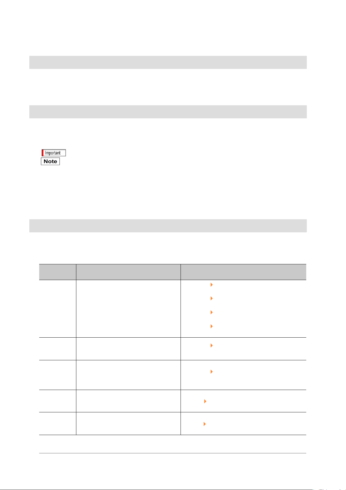
Conventions Used in This Manual
Symbols
The symbols used in this manual have the following meanings.
Indicates relevant operational precautions that must be followed.
Indicates operation-related suggestions from OMRON.
Use of Quotation Marks and Brackets
In this manual, menus and other items are indicated as follows.
[ ] Menu Indicates the menu names or processing items shown in the menu bar.
" " Item name Indicates the item names displayed on the screen.
Version Upgrade Information
The newly added functions are described here.
Revision history
Newly added
function
Measurement
flow control
function
Operation log
function
Registered
image
management
function
Security
setting
function
Customize I/O
command
function
Description of newly added functions Reference in manual
The measurement flow control function is
now supported.
Supported software version: 4.20 or later
The operation log function is now
supported.
Supported software version: 4.20 or later
The registered image management function
is now supported.
Supported software version: 4.20 or later
The security setting function is now
supported.
Supported software version: 4.20 or later
The custom command function is now
supported.
Supported software version: 4.20 or later
Reference: "Processing Items List Manual",
"Fieldbus Flow Control" (p.556)
Reference: "Processing Items List Manual", "PLC
Link Flow Control" (p.561)
Reference: "Processing Items List Manual",
"Parallel-flow Control" (p.565)
Reference: "Processing Items List Manual",
"Non-procedure Flow Control" (p.569)
Reference: "User's Manual", "Using the Operation
Log Functions" (p.104)
Reference: "User's Manual", "Using Registered
Image Administration Tool" (p.132)
R efere n ce : "U se r's M an u al" , "U sin g A c c ou n t F un c tio n s" ( p .1 36 )
R e f e re nc e : "U se r 's M an u al" , "U sin g C u sto m C om m a nd s" (p .1 5 2 )
6 FZ4 User's Manual
Page 9

Com
munica tion
command
addition
EtherNet/IP
message
communication
function
The communication command is now
added.
Supported software version: 4.20 or later
The EtherNet/IP message communication
function is now supported.
Supported software version: 4.20 or later
Reference: "User's Manual", "Methods for Connecting
and Communicating with External Devices" (p.359)
Reference: "User's Manual", "Communicating with
the controller with Ethernet/IP message
communications" (p.536)
FZ4 User's Manual 7
Page 10
Regulations and Standards
● Using Product Outside Japan
This regulation applies to FZ4 sensor controller and peripheral devices.
If you export (or provide a non-resident with) this product or a part of this product that falls under the
category of goods (or technologies) specified by the Foreign Exchange and Foreign Trade Control Law as
those which require permission or approval for export, you must obtain permission or approval or service
transaction permission) pursuant to the law.
● Conformance to EC Directives
This regulation applies to FZ4 sensor controller and peripheral devices.
The FH Sensor Controller is compliant with the standards below:
• EMC Directives(2004/108/EC)EN61326-1
Electromagnetic environment : Industrial electromagnetic environment (EN/IEC 61326-1 Table 2)
• Also, the following condition is applied to the immunity test of this product.
: If the level of disturbance of the video is such that characters on the monitor are readable, the test is a
pass.
• This product complies with EC Directives.EMC-related performance of the OMRON devices that
comply with EC Directives will vary depending on the configuration, wiring, and other conditions of
the equipment or control panel on which the OMRON devices are installed.
• The customer must, therefore, perform the final check to confirm that devices and the overall
machine conform to EMC standards.
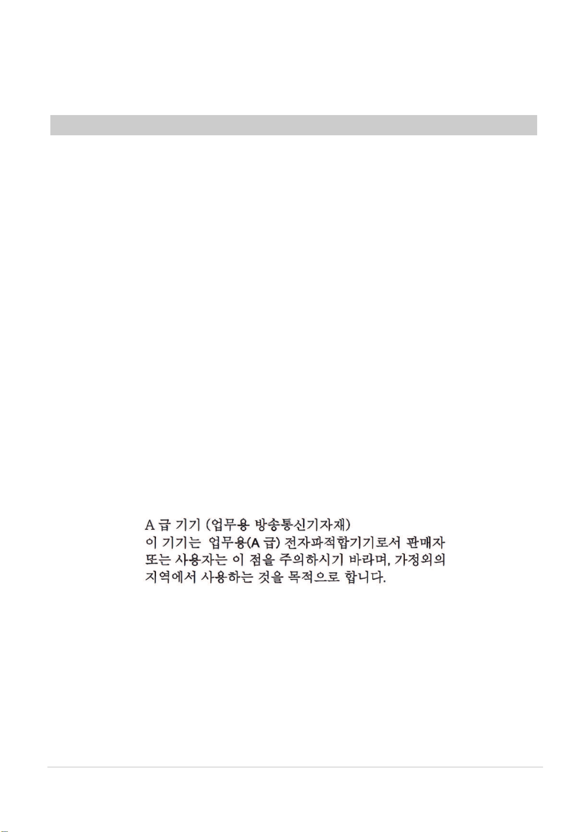
● Conformance to KC Standards
Observe the following precaution if you use this product in Korea.
• Class A Device (Broadcasting Communications Device for Office Use)
This device obtained EMC registration for office use (Class A), and it is intended to be used in places
other than homes.
Sellers and/or users need to take note of this.
● Conformance to CSA Standards
This regulation applies to FZ4 sensor controller and peripheral devices.
This product complies with CSA Standards.
CSA C22.2 No.61010-1
8
FZ4 User’s Manual
Page 11

Before Operation
This chapter describes the basic flow and preparations
before beginning operation.
Reference: Operation Flow (p.10)
Reference: Layouts of Screens/Windows (p.11)
Reference: Checking System Configuration (p.21)
Reference: Preparing Controllers and Cameras (p.23)
Reference: Input Operations (p.25)
Reference: Returning Controller to Factory Settings (p.27)
Reference: Saving Settings and Turning Power Off (p.28)
Reference: Setting Operation Mode (p.30)
1
Before Operation
FZ4 User's Manual 9
Page 12
1
Before Operation
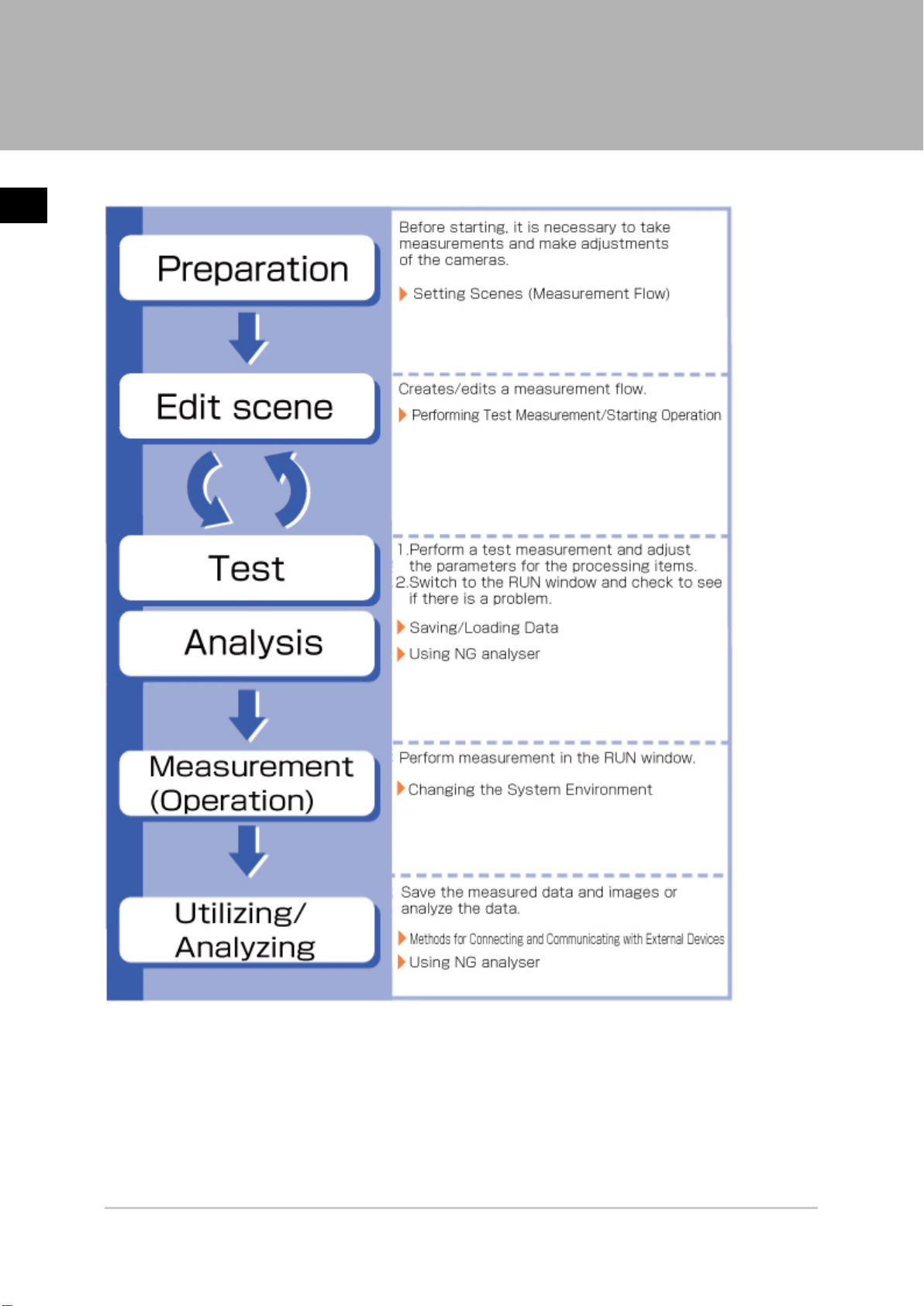
Operation Flow
Here describes the operation flow.
10 Operation Flow FZ4 User's Manual
Page 13

Layouts of Screens/Windows
Screens vary with the status of the operation being performed. The structure of some typical screens
and the functions for the various buttons are described here.
1
Before Operation
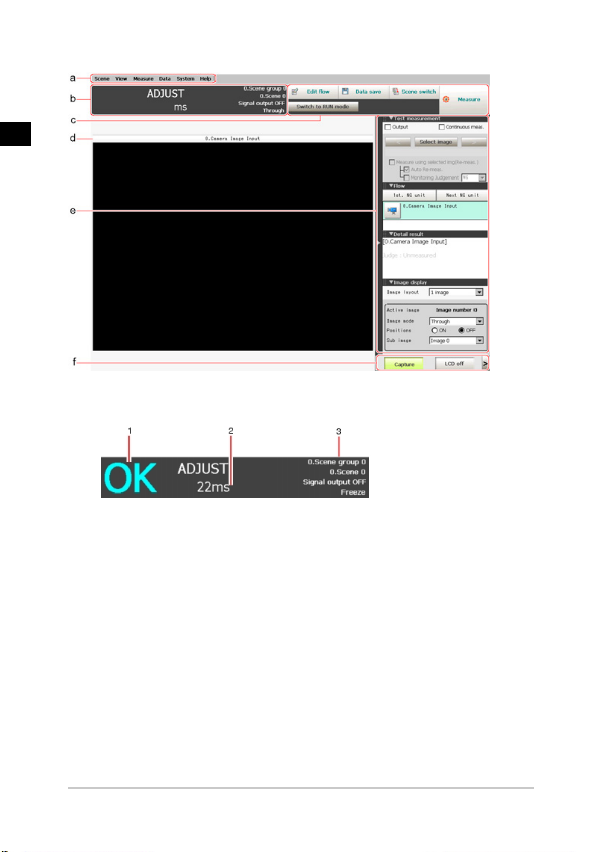
Layout of Main Screen (ADJUST Window)
This screen is used to check whether measurement is being performed correctly according to the set
conditions.
FZ4 User's Manual Layouts of Screens/Windows 11
Page 14
1
Before Operation
Menu Bar
a.
Select operations and settings menus related to measurement.
Measurement Information Display Area
b.
Overall judgement
1.
Displays a scene's overall judgement result ( [OK]/ [NG]).
Processing time
2.
Displays the time required for the measurement process.
Status display
3.
Displays the scene group number, scene number, external output status, and image mode
for the currently displayed scene.
Toolbar
c.
Commonly-used functions appear in the toolbar.
●
Edit flow
The Edit Flow window is displayed. Addition and deletion of processing units and switching
of the processing sequence is performed in the Edit Flow window.
●
Data save
Setting data is saved into the internal flash memory in the controller. Make sure to save
when settings have been modified.
●
Scene switch
To switch a scene group or scene.
●
Measure/Stop meas.
12 Layouts of Screens/Windows FZ4 User's Manual
Page 15
Starts/stops measurement.
●
Switch to RUN mode
Switches to the RUN window.
Image Display Area
d.
Displays the measured image.
Property setting buttons
1.
Displays the name of the currently selected processing item.Moving to the property setting
window can be done by tapping here.
Control Area
e.
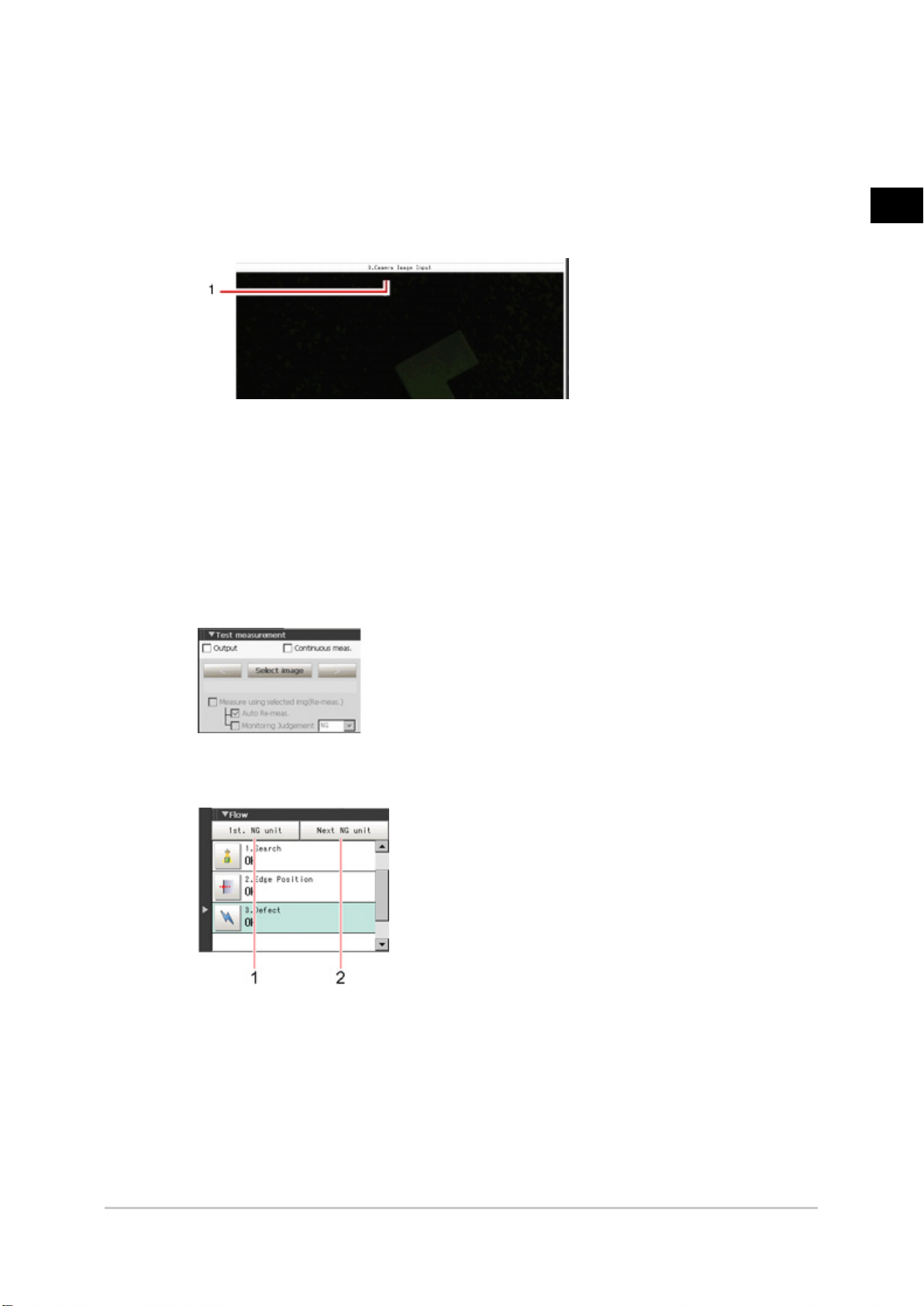
Displays "Test measurement", "Flow", "Detail result", and "Image display".
●
Test measurement
Use when test measurement conditions and images that have been acquired are used for
remeasurement.
1
Before Operation
●
Flow
Displays the judgement results for the flow and each unit.
1. Moves to the top processing unit with an NG error.
2. Moves to the next processing unit with an NG error.
●
Detail result
The detailed measurement results of the processing units selected in the measurement
flow are displayed as text.
FZ4 User's Manual Layouts of Screens/Windows 13
Page 16
1
Before Operation
●
Image display
Sets the display method for the Image Display area.
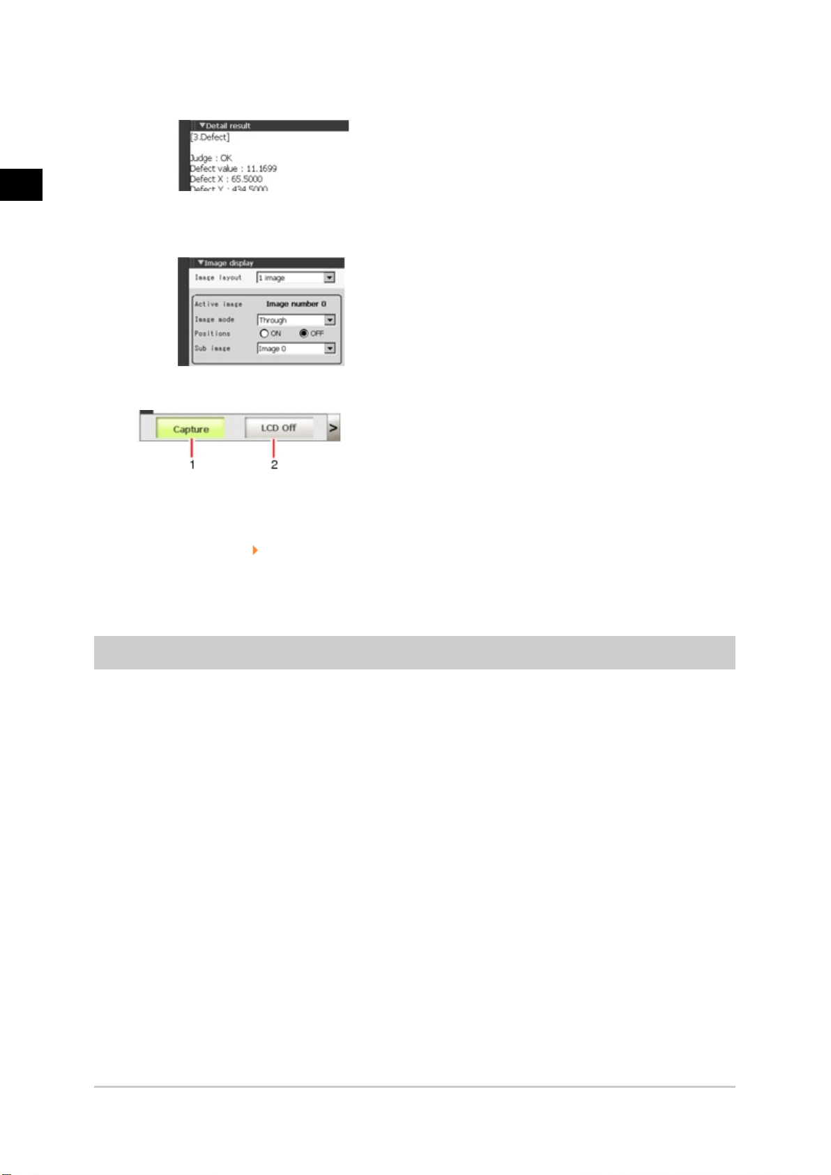
Measurement Manager Bar
f.
[Capture]
1.
Saves the content displayed on the monitor as an image.
Reference: Set the save destination for captured images. (p.104)
[LCD Off] (Displayed only with LCD-integrated controllers.)
2.
Turns off power to the LCD monitor. Tap the bottom of the monitor screen to turn on power
to the LCD monitor again.
Layout of Main Screen (RUN Window)
This window is used during operation.
14 Layouts of Screens/Windows FZ4 User's Manual
Page 17
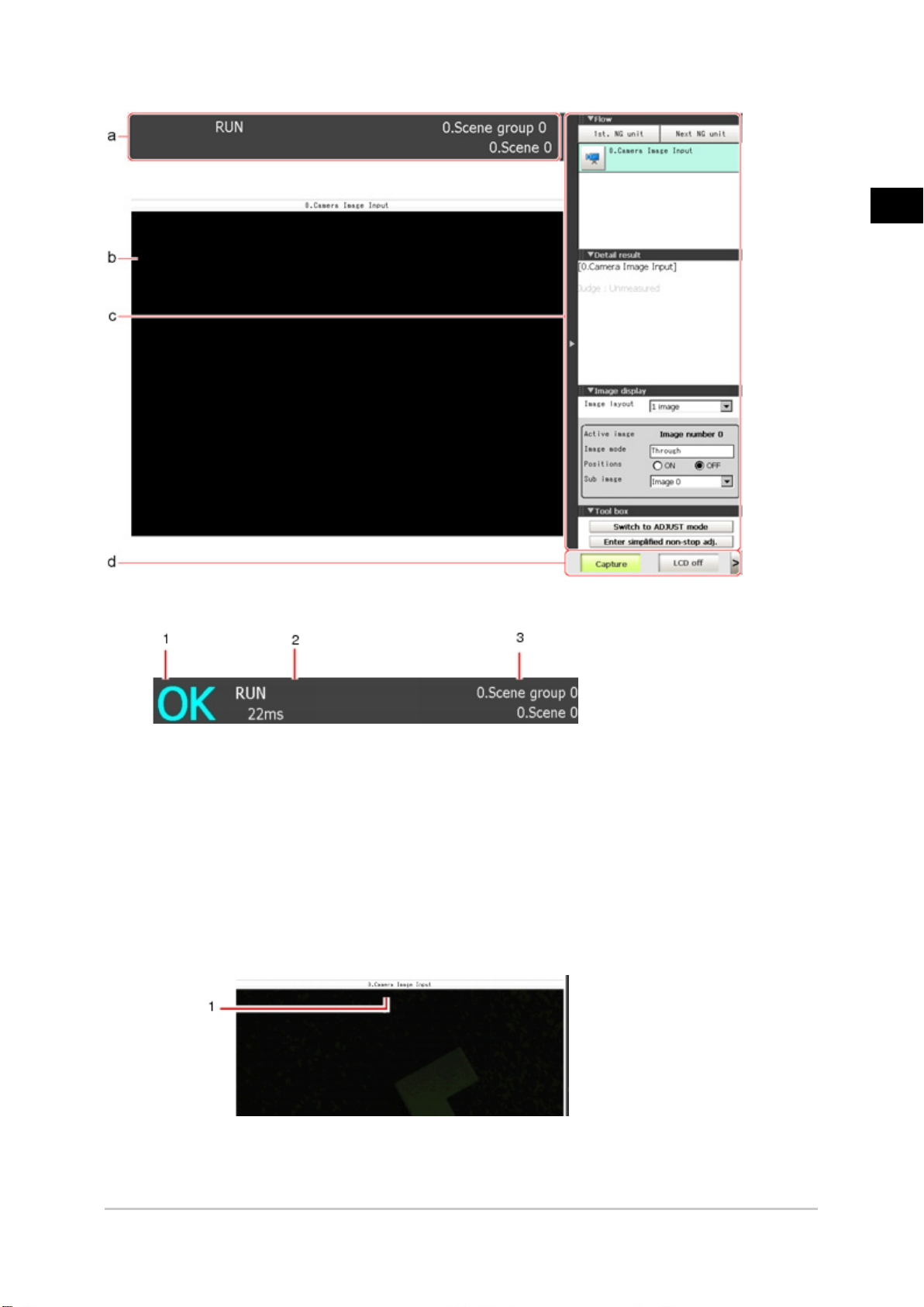
Measurement Information Display Area
a.
1
Before Operation
Overall judgement
1.
Displays a scene's overall judgement result ( [OK]/ [NG]).
The judgement results for each processing unit are displayed in the Control area.
Processing time
2.
Displays the time required for the measurement process.
Scene Group Name, Scene Name
3.
Displays the scene group number and the scene number of the currently displayed scene.
Image Display Area
b.
Displays the measured image.
Property setting buttons
1.
Displays the name of the currently selected processing item.
FZ4 User's Manual Layouts of Screens/Windows 15
Page 18
1
Before Operation
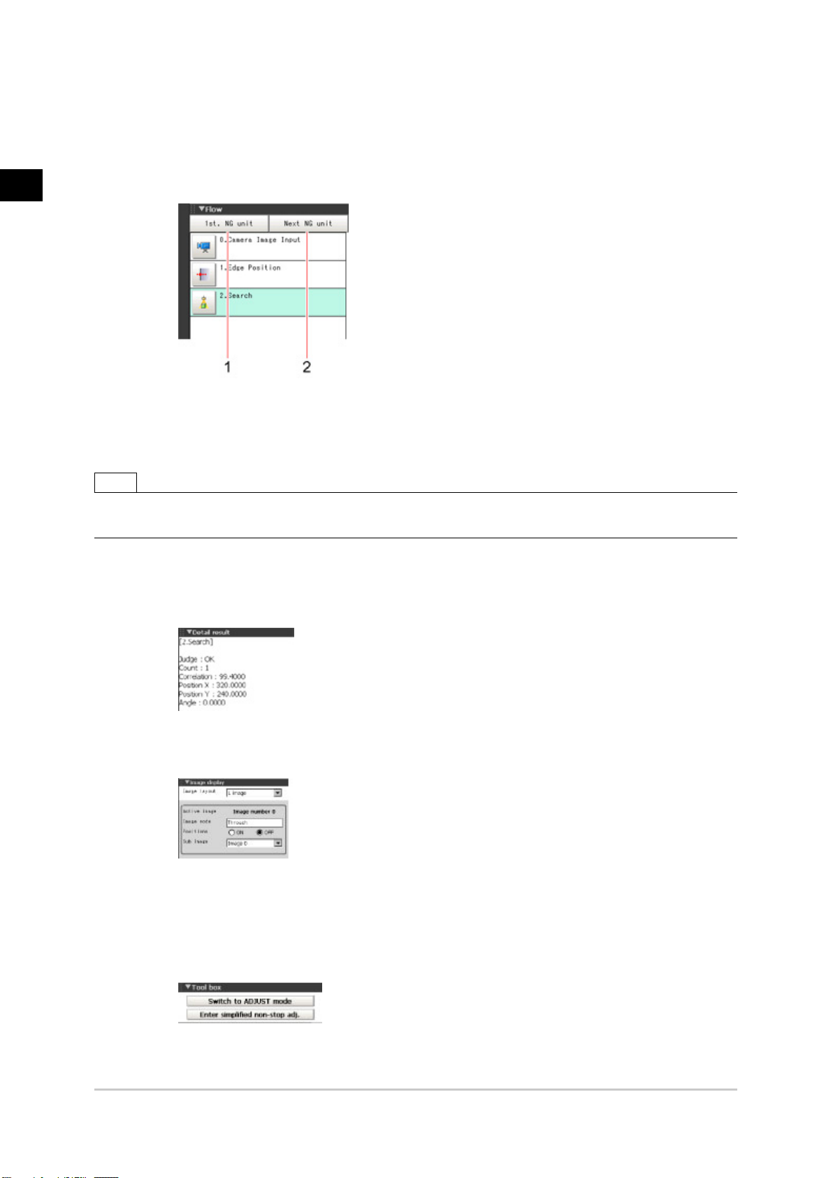
Control Area
c.
Displays [Flow], [Detail result], [Image display], and [Tool box].
●
Flow
Displays the judgement results for the flow and each unit.
1. Moves to the top processing unit with an NG error.
2. Moves to the next processing unit with an NG error.
Note
●
The size of the processing unit buttons can be changed through [View] menu - [Display the enlarged flow] in the
ADJUST Window.
●
Detail result
The detailed measurement results of the processing units selected in the measurement
flow are displayed as text.
●
Image display
Sets the display method for the Image Display area.
●
Tool box
Starts and stops simplified non-stop adjustment, and switches to the ADJUST window.
Items for which operation is performed in the ADJUST window can be allocated to buttons,
and they can then be executed in the RUN window.
16 Layouts of Screens/Windows FZ4 User's Manual
Page 19
Measurement Manager Bar
d.
[Capture]
1.
Saves the content displayed on the monitor as an image.
Reference: Set the save destination for captured images. (p.104)
[LCD Off] (Displayed only with LCD-integrated controllers.)
2.
Turns off power to the LCD monitor. Tap the bottom of the monitor screen to turn on power
to the LCD monitor again.
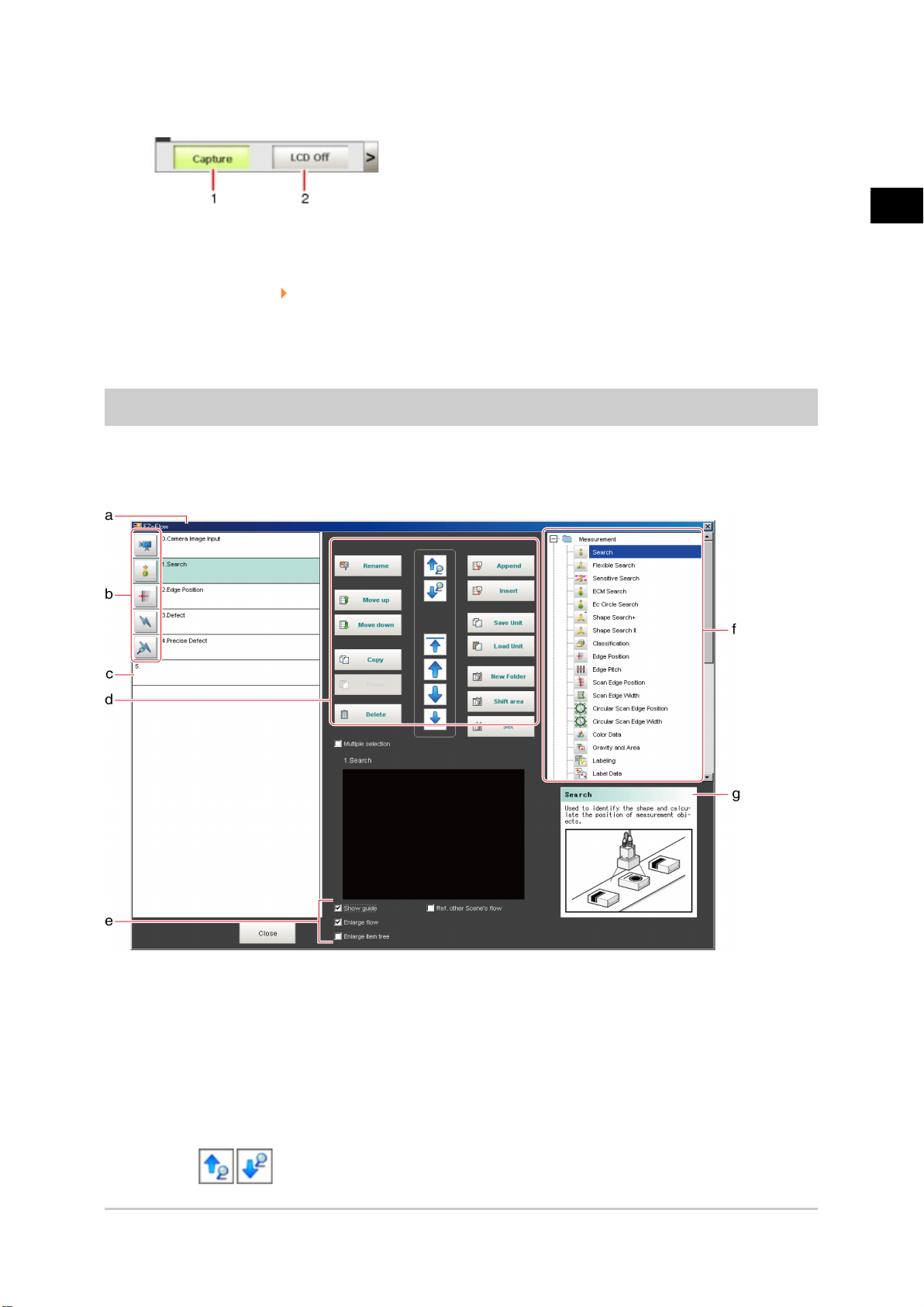
Layout of Edit Flow Window
This window is for compiling the measurement flow.Flow parts are displayed on the right side and the
measurement flow is displayed on the left. If the measurement trigger is activated, processing is
executed in sequence starting from the top of the flow.
1
Before Operation
Unit List
a.
Lists the processing units included in the flow.
You can create a flow for a scene by adding processing items to the unit list.
Property Setting Buttons
b.
Displays the property setting window where detailed settings can be performed.
End Marker
c.
Indicates the end of the flow.
Edit Flow Buttons
d.
●
FZ4 User's Manual Layouts of Screens/Windows 17
Search up/Search down
Page 20

1
Before Operation
Searching can be performed to find out what position a processing item occupies in the
unit list.
The icon for the processing item to be searched for is selected in the processing item tree
and clicked.
This function is convenient when setting long flows.
●
Select top/Select bottom
Selects the processing unit at the top or bottom of the flow.
●
Select above/Select below
Selects the processing unit located one above or one below the currently selected
processing unit.
●
Rename
Displays a window for renaming the selected processing unit.
●
Move up/Move down
Moves the selected processing unit upward or downward.
●
Copy
Copies the selected processing unit.
●
Paste
Pastes the copied processing unit immediately before the selected processing unit.Pasting
cannot be performed if any operations other than paste are performed after copying.
●
Delete
Deletes the selected processing unit.
●
Append (Bottom)
Adds a processing unit to the bottom of the flow.
●
Insert
Inserts a new processing unit immediately before the selected processing unit.
●
Save unit
This saves the selected processing unit setting data to a file. More than one processing
units cannot be saved to one file. However, when saving entire folders, it is possible to
save more than one processing units to one file.
The default file name is S (scene number)_U (unit number)_(processing unit identifier).unt.
(Can be changed as desired)
Example) Scene 0 unit 0 "Camera Image Input"
S0_U0_CameraImage
●
Load unit
This reads the processing unit setting data from a file.
Files other than those saved in Saving unit cannot be read.
Upon reading the file, specify the reference, such as the destination or expression, again.
●
New folder
Used when multiple processing units are managed as one group.
●
Shift area
Changes related figure data in one batch.
●
Multiple selection
Used when processing units are copied or deleted together.
●
Set
Displays the processing item setting window for the selected processing unit.
Display Options
e.
18 Layouts of Screens/Windows FZ4 User's Manual
Page 21
●
Show guide
When checked, explanations for processing items are displayed.
●
Enlarge flow
When checked, the "a Unit list" flow is displayed with large icons.
●
Enlarge item tree
When checked, the "f Processing item tree" is displayed with large icons.
●
Ref. other Scene's flow
When checked, other scene flows within the same scene group can be referred to.
Processing Item Tree
f.
This area is for selecting processing items to add to the flow.Processing items are classified by
type and displayed as a tree. Tapping the plus sign "+" of any item displays expanded contents
below that item. Tapping the minus sign "-" of any item collapses the expanded contents.
When "Ref. other Scene's flow" is checked, the scene select box and other scene flows are
displayed.
Guide
g.
Shows an explanation for the processing item selected in the processing item tree.These are
used as reference when selecting processing items. To display guides, check "Show guide" in "e
Display options".
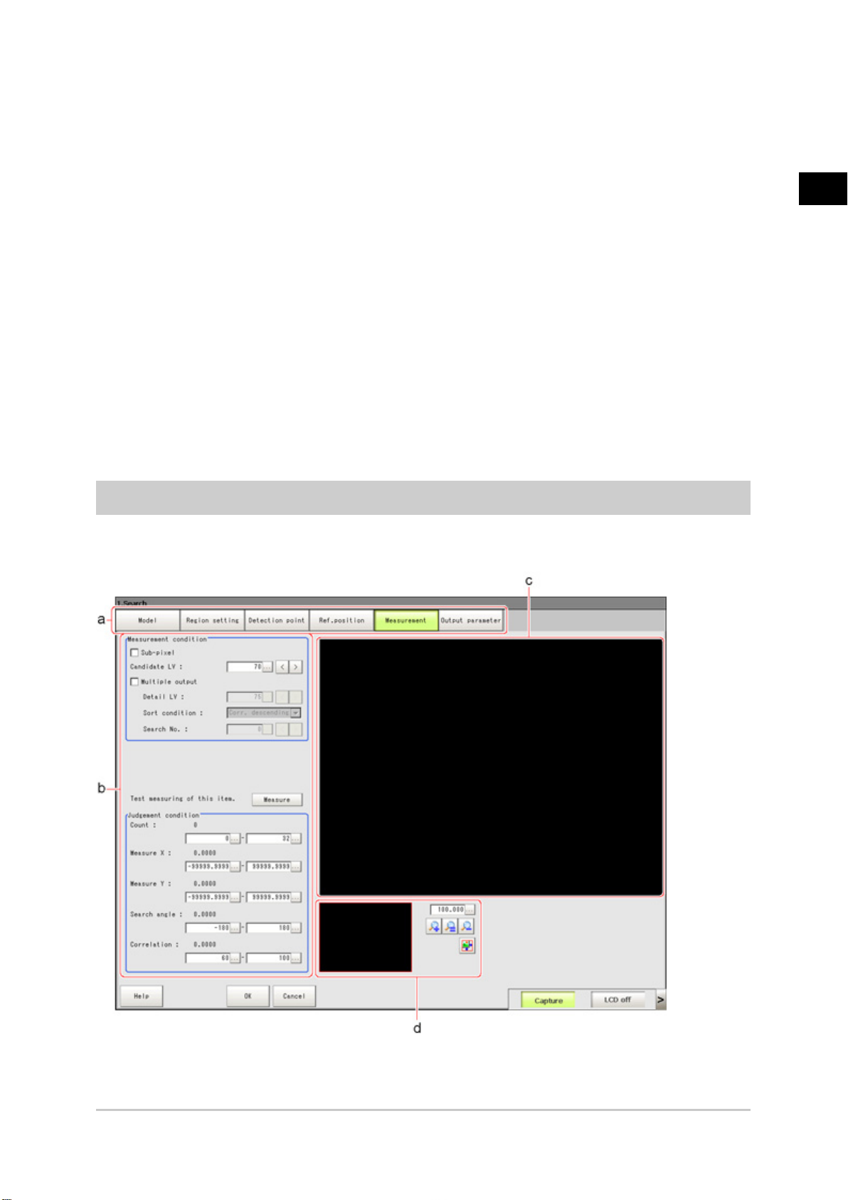
Layout of Property Setting Window
1
Before Operation
This window is used for detailed setting of measurement parameters and judgement conditions for
processing items.
Item Tab Area
a.
Displays the settings items for the processing unit currently being set.Perform settings starting
FZ4 User's Manual Layouts of Screens/Windows 19
Page 22

1
Before Operation
with the item on the left.
Detail Area
b.
Set detailed items.
Image Display Area
c.
Displays camera images, figures, and coordinates.
Zoom Browser Area
d.
Zooms in and out from the displayed image.
20 Layouts of Screens/Windows FZ4 User's Manual
Page 23
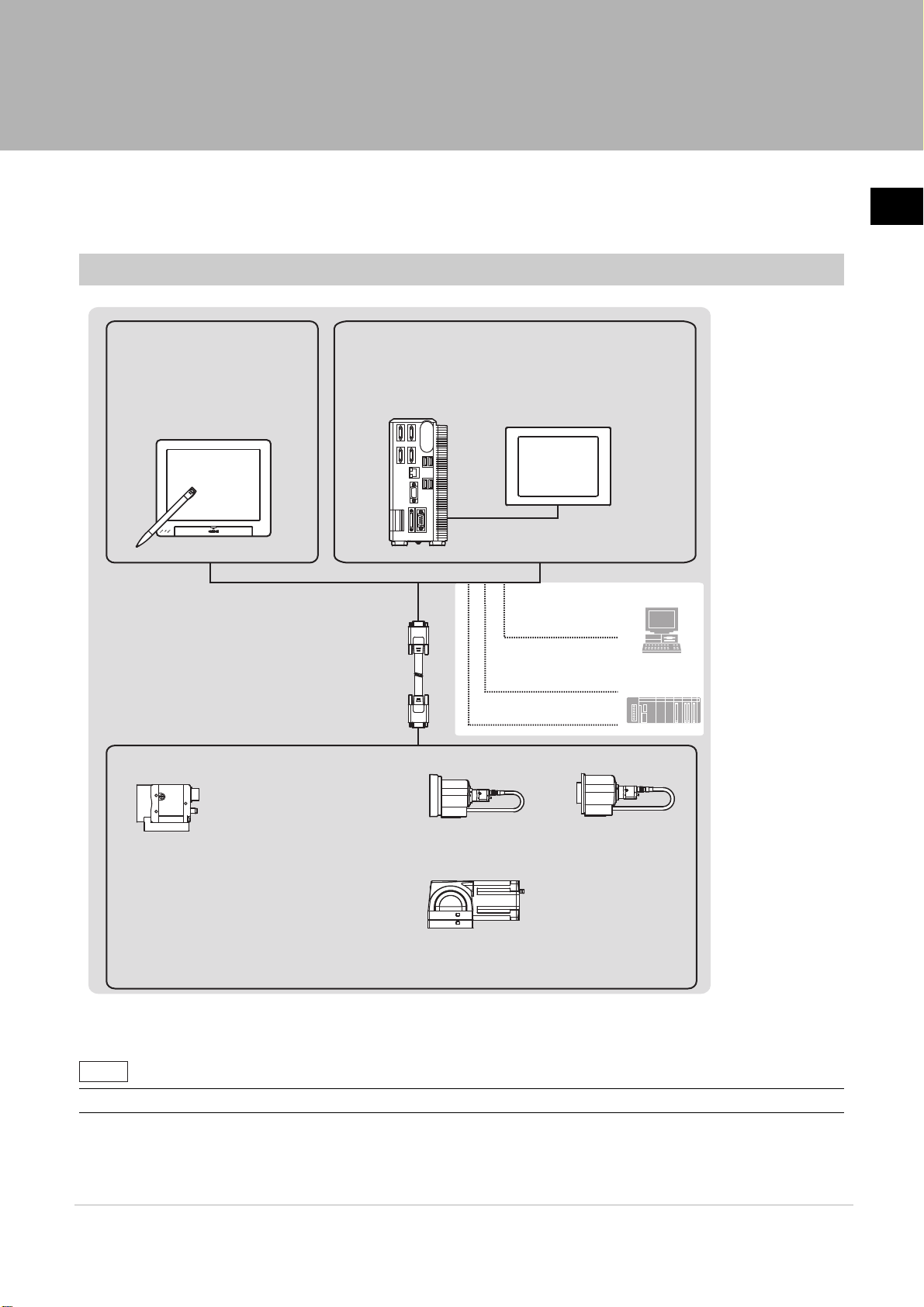
Checking System Configuration
PLC
LCD monitor
Parallel I/O cable
FZ-VP
Touch pen
(*1)
FZ-M08
Ethernet
PC
RS-232C/422 cable
- 300,000-pixel
Color/Monochrome camera
Stand-alone
camera
Controller integrated with LCD
FZ4-60@/FZ4-60@-10/
FZ4-H60@/FZ4-H60@-10/
FZ4-70@/FZ4-70@-10/
FZ4-H70@/FZ4-H70@-10/
FZ4-110@/FZ4-110@-10/
FZ4-H110@/FZ4-H110@-10
Box-type Controller
FZ4-L35@/FZ4-L35@-10/
FZ4-65
@
/FZ4-65@-10/FZ4-H65@/FZ4-H65@-10/
FZ4-75
@
/FZ4-75@-10/FZ4-H75@/FZ4-H75@-10/
FZ4-115
@
/FZ4-115@-10/FZ4-H115@/FZ4-H115@-10
CCTV lens and lighting are required.
FZ-SLC15/FZ-SLC100
FZ-SZC15/FZ-SZC100
300,000-pixel Small-size flat type
Color/Monochrome camera
FZ-SF/FZ-SFC
(*2)
300,000-pixel Small-size pen type
Color/Monochrome camera
FZ-SP/FZ-SPC
(*2)
- 5 million-pixel camera
Color/Monochrome camera
FZ-SC5M2/FZ-S5M2
- 2 million-pixel
(*2)
Color/Monochrome camera
FZ-SC2M/FZ-S2M
Monitor cable
<Input device>
Mouse, trackball (commerciallyavailable item with USB interface)
FZ-VM
Intelligent camera Auto-focus camera
Camera cable FZ-VS
Long-distance camera cable FZ-VS2
Bend camera cable FZ-VSB
Right angle camera cable FZ-VSL
Cable extension unit FZ-VSJ
FZ-SC/FZ-S
FZ-SQ@@@@
Intelligent compact camera
Reference
This product is a vision sensor for performing image processing measurement through a controller of objects
photographed using a camera. By connecting an external device such as a PC, measurement commands can
be input and measurement results can be output from the external device.
Basic Configuration of FZ4 Series
1
Before Operation
*1: The touch pen is a controller accessory.
*2: Lenses for small-size cameras are required for small-size 0.3 megapixel cameras.
• For details on connector specifications, etc., see the "Operator's Manual (Setup)" of each model.
Checking System Configuration 21FZ4 User’s Manual
Page 24
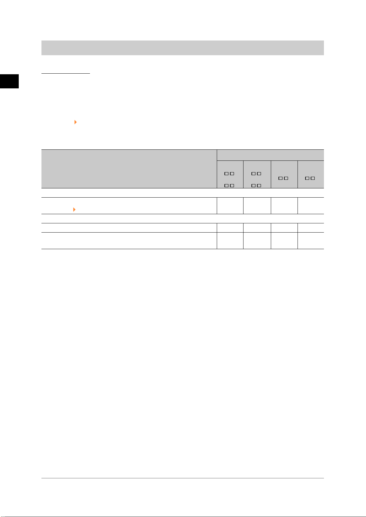
Description of Model-specific Functions
Operation mode
1
Before Operation
With the multi core CPU installed, different operation modes can be set to meet different purposes of
use.
A desired operation mode can be selected from [Parallel-operation high-speed mode], [Single-line
high-speed mode], [High-speed logging mode], [Non-stop adjustment mode] and [Multi-line
random-trigger mode].
Reference: Setting Operation Mode (p.30)
List of functions by model
Type of controller
New function
Function
Operation mode
Reference: Setting Operation Mode (p.30)
Processing item
Standard processing item
Sophisticated processing item (processing item having + at the end of
the item name)
FZ4-6
FZ4-7
- -
Sup p o
-
FZ4-H6
FZ4-H7
rtedSupported
Supported
FZ4-11
Sup p o
Sup p o
-
F Z 4-H 1 1
rtedSup p o
rtedSup p o
Sup p o
rte
rte
rte
d
d
d
22 Checking System Configuration FZ4 User's Manual
Page 25
Preparing Controllers and Cameras
Preparing Controllers
No special preparation is required with this product as processing items are pre-installed.Please check
that the controller is switched on and that the Main screen is displayed.
For details, see the User's Manual.
The first time the program is started up, the Language Setting window is displayed, so select the
language.
Reference: Selecting the Language [Language Setting] (p.345)
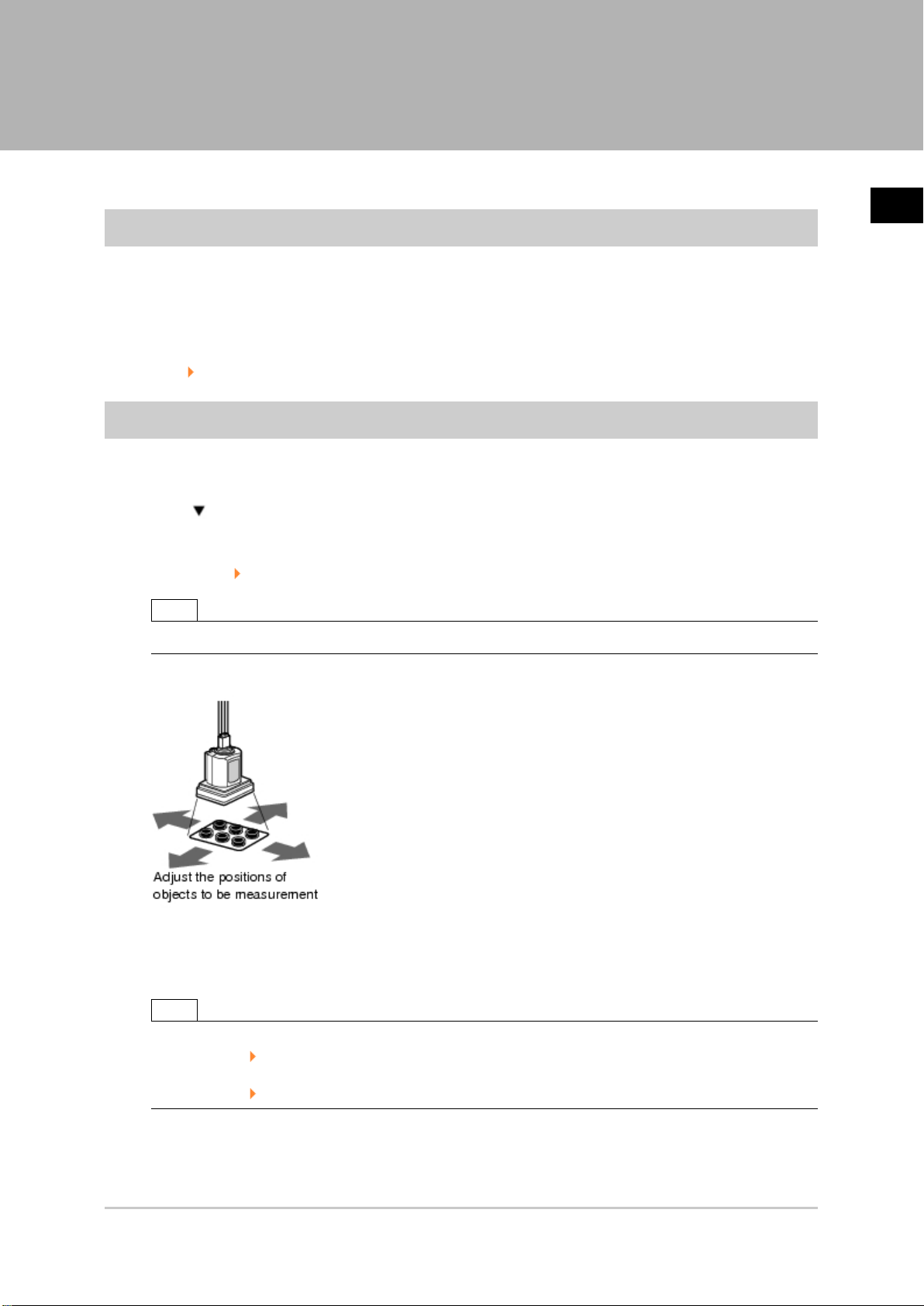
Adjusting Cameras
Confirm what kind of images are being taken.
Adjust the position of measurement objects and the focus of the lens.
Tap [ ] of "Image mode" in [Image display] of the Main screen Control area, and select
1.
"Through".
The through images captured from the camera are viewed in the Image Display area.
Reference: Changing Display Contents (p.83)
1
Before Operation
Note
●
The same operation is available by tapping [View] - [Image mode] - [Through].
Adjust the position of measurement objects so that they display at the center of the monitor.
2.
Adjust the focal distance of the lens.
3.
When using an auto-focus camera or an intelligent camera, focus and the iris can be
automatically adjusted.
Note
●
If a camera is used together with a lens, turn the focus ring of the lens to adjust the focus.
Reference: "Processing Item List Manual", "Lens Setting" (p.29)
●
The light intensity of an intelligent camera can be adjusted from the controller.
Reference: "Processing Item List Manual", "Lighting Control" (p.25)
FZ4 User's Manual Preparing Controllers and Cameras 23
Page 26
1
Before Operation
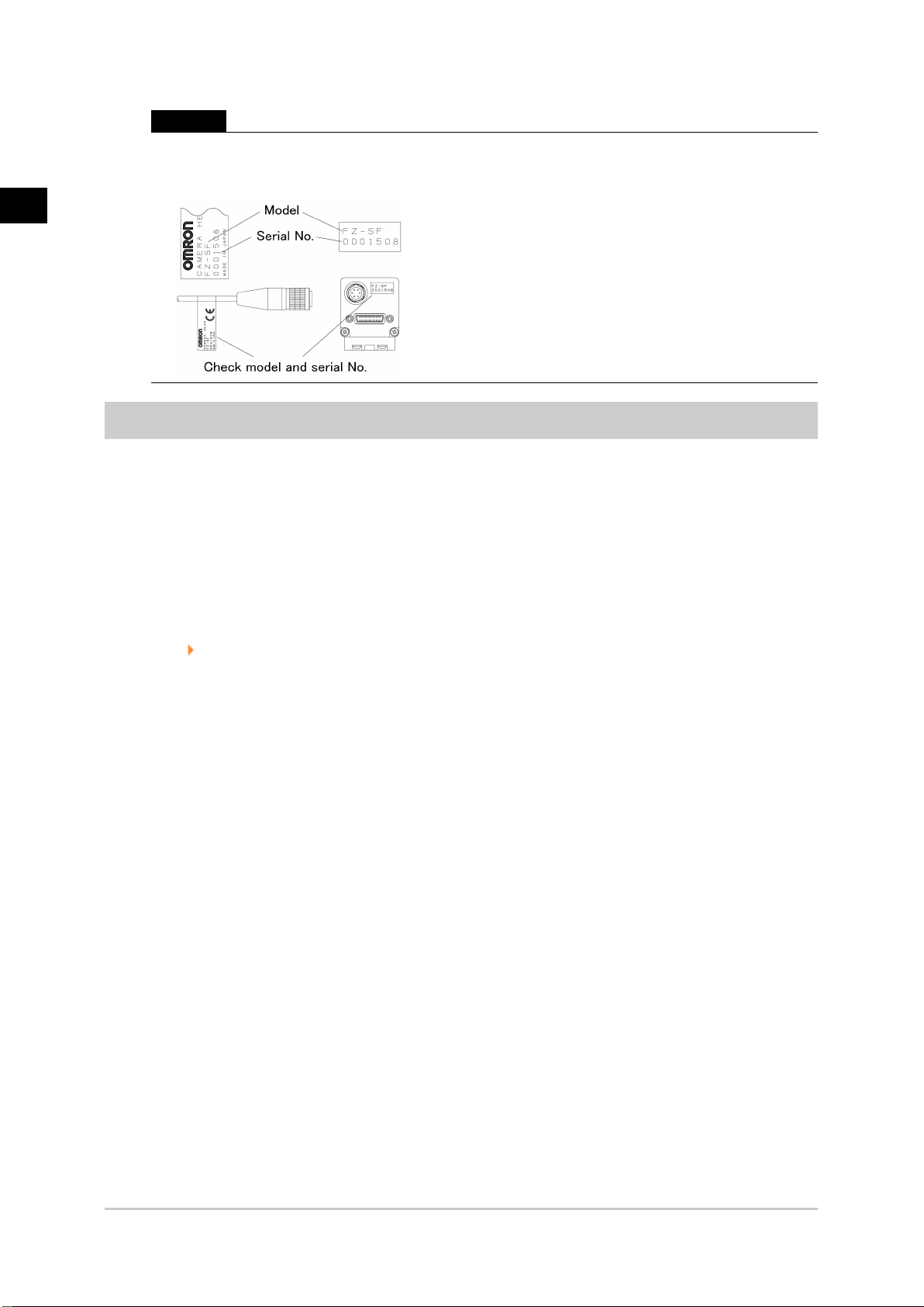
Important
●
When using a small-size digital camera, check that the model and serial number of the camera head
and camera amplifier match.When a camera head and camera amplifier of different models and serial
numbers are connected, they may not operate correctly.
Intelligent Camera (with Lighting Function)
Proper lighting is of crucial importance to vision sensors.
If an intelligent camera is connected, lighting can be controlled from the controller.
Features of intelligent cameras are as follows:
●
A single camera enables testing of illumination from various angles, so it is possible to shorten
the lighting setting time and test measurement time.
●
The controller controls lighting, so lighting can be adjusted depending upon the product type.
●
Reproducibility of lighting settings is improved.
●
Settings can be modified without changing lighting.
Reference: "Processing Items List Manual", "Screen Adjust Settings (Camera Image Input)" (p.25)
24 Preparing Controllers and Cameras FZ4 User's Manual
Page 27
Input Operations
Input operations differ depending on the type of controller.
●
Controller integrated with LCD: Operation with touch pen
●
BOX-type controller: Operation with mouse and trackball
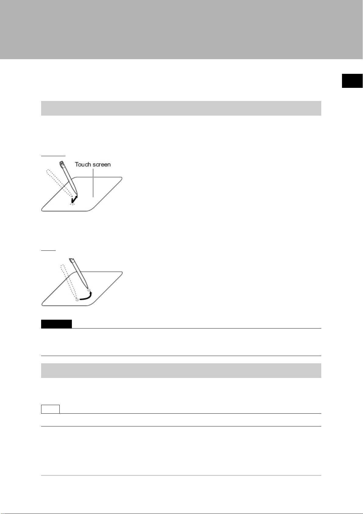
Operation of Touch Pen
With a Controller integrated with LCD, perform the following operations when operating the touch screen
with the touch pen.
Tapping
Lightly touch the screen once with the touch pen and immediately take it off. Perform when selecting
items, etc.
1
Before Operation
Drag
Draw while pressing on the screen lightly with the touch pen.
Important
●
Be sure to use the supplied touch pen for touch screen operations.Using a pencil or ballpoint pen may damage
the touch screen.
●
In addition, response to operations may be delayed if the screen is tapped continuously and rapidly.
Basic Operation of Mouse and Trackball
With a BOX-type controller, use a mouse with a USB interface or commercially-available trackball.
(See the list for recommended products. Please refer to the product catalog.)
Note
●
Do not use the right mouse button, scroll wheel, or other buttons.
FZ4 User's Manual Input Operations 25
Page 28
1
Before Operation
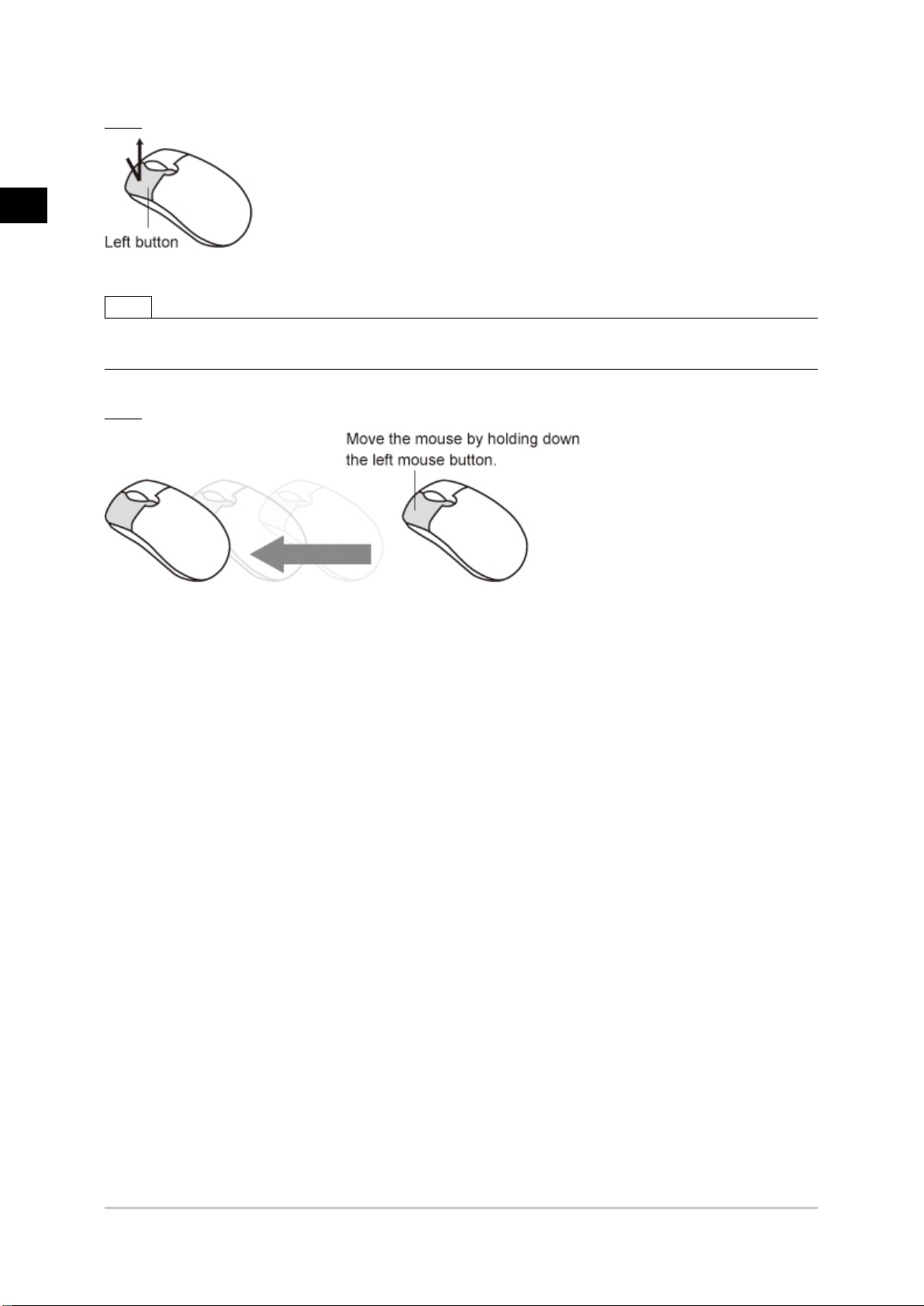
Click
Press the left mouse button once. Perform when selecting items, etc.
Note
●
This document primarily describes operations using the term "tapping". When using a mouse or trackball, read
"Tapping" to mean "Clicking".
Drag
Move the mouse with the left mouse button held down.
26 Input Operations FZ4 User's Manual
Page 29
Returning Controller to Factory Settings
All controller settings can be restored to factory default status (initialization).
In addition, the controller can be restarted.
●
Reference: Initializing Controller [System Initialization] (p.27)
●
Reference: Restarting Controller [System Restart] (p.27)
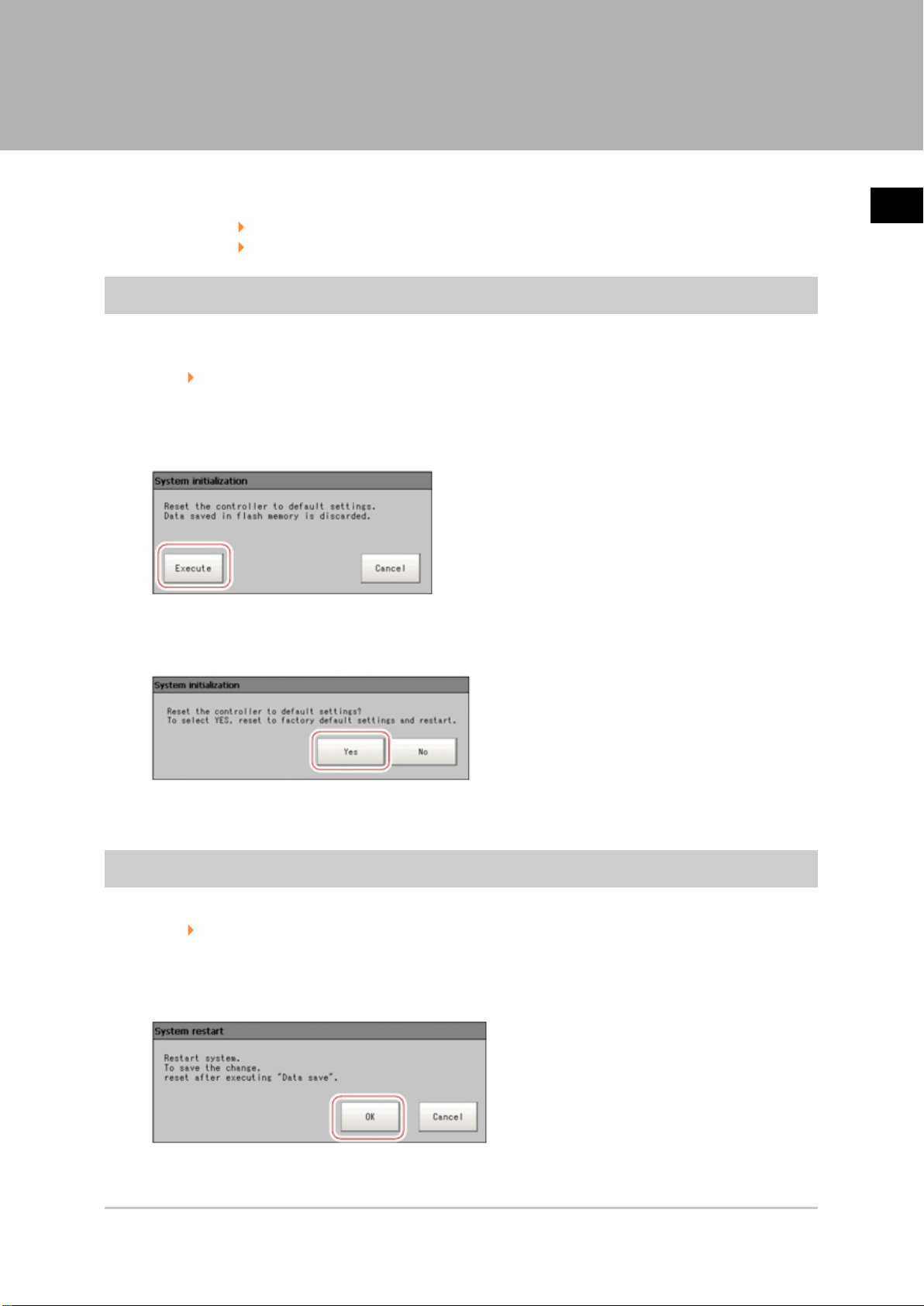
Initializing Controller [System Initialization]
Restores the controller to factory default status. Before initialization, back up required data such as
scene data and system data.
Reference: Saving Settings Data to RAMDisk/USB Device (p.334)
On the Main screen, tap [System] - [Controller] - [System initialization].
1.
The System Initialization window is displayed.
Tap [Execute].
2.
1
Before Operation
A confirmation window is displayed.
Tap [Yes].
3.
The controller is initialized and restarts.
Restarting Controller [System Restart]
Restart the controller. Before restarting, back up required data such as scene data and system data.
Reference: Saving Settings Data to Controller Memory (p.332)
On the Main screen, tap [System] - [Controller] - [System restart].
1.
The System Restart window is displayed.
Tap [OK].
2.
The controller restarts.
FZ4 User's Manual Returning Controller to Factory Settings 27
Page 30
1
Before Operation
Saving Settings and Turning Power Off
Before turning off power to the controller, perform the following operations to save the data that you
have set.
The controller loads scene data from the flash memory each time during start-up. Therefore, if the power
is turned off without saving data to the flash memory, any changes made will not be saved.
On the Main screen (ADJUST window), tap [Data save] in the toolbar to save the setting data.
1.
Exit after powering off the controller.
2.
Note
●
Data to be saved
Scene data and system data are saved in the controller. Logging images and data saved in the RAMDisk
are not saved. Perform any of the following procedures to keep this data.
- Copy data saved in the RAMDisk to the USB memory.
Reference: Copying/Moving Files (p.338)
- Change the save destination of logging data to USB memory.
Reference: Saving Logging Images to RAMDisk/USB Device (p.336)
●
When using the scene group function
The scene data set in Scene group 0 is saved in the controller. The scene data from scene groups 1 to
31 is saved to the USB memory and overwrites previous saved data. (For FZ4-11 /H11 , all
data are saved in the controller.)
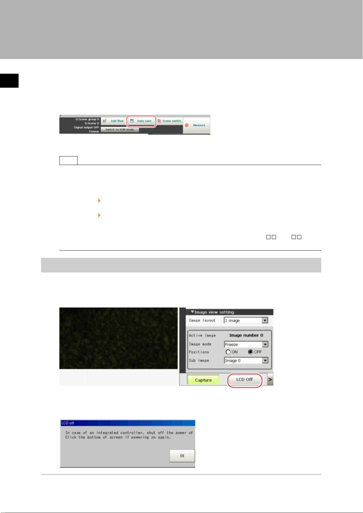
Turning Off LCD
This function is specific to FZ4-600/700/1100 series LCD-integrated controllers.
Turn off the LCD only without turning off the controller.
Open the measurement manager bar at the bottom right of the Main screen and tap [LCD Off].
1.
A confirmation message is displayed.
Tap [OK].
2.
28 Saving Settings and Turning Power Off FZ4 User's Manual
Page 31

Power to the LCD is turned off.
Turning LCD On Again
This function is specific to FZ4-600/700/1100 series LCD-integrated controllers.
Tap the lower part of the monitor screen.
Then, the LCD will be switched on.
1
Before Operation
FZ4 User's Manual Saving Settings and Turning Power Off 29
Page 32

1
Before Operation
Setting Operation Mode
This section describes the operation mode (FZ4-11 /H11 only). Utilize the multi core CPU to
set an operation mode appropriate for the condition of use. This function is effective in improving the takt
time and reducing the downtime. For setting, use Startup setting.
Reference: Setting the Start-up Status "Startup Setting" (p.347)
On the Main screen, tap the [System] menu - [Controller] - [Startup setting].
1.
Tap [Operation mode].
2.
30 Setting Operation Mode FZ4 User's Manual
Page 33

Tap [ ] and select a desired operation mode.
3.
1
Before Operation
Tap [OK].
4.
On the Main screen (ADJUST window), tap [Data save] in the toolbar to save the setting data.
5.
On the Main screen, tap [System] menu - [Controller] - [System restart].
6.
The System Restart window is displayed.
Tap [OK].
7.
FZ4 User's Manual Setting Operation Mode 31
Page 34

Operation Mode Selection Guidelines
1
Before Operation
This section describes how to set an operation mode suitable for your specific purpose.
[Note 1]: Reference: About Multiple Image Input Function (p.559)
High-speed Logging Mode
Normally one CPU is used to perform measurement, image logging and image display. The FZ4-11
/H11 series performs processing using two CPUs, with one CPU used exclusively for measurement
and the other performing non-measurement processing. This ensures maximum measurement
performance at all times.
Parallel-operation High-speed Mode
Two CPUs are used to share and process measurement tasks internally. Processing is executed in
parallel to shorten the measurement time to maximal 50%.
Parallel processing is performed for each processing unit to shorten the total processing time.
32 Setting Operation Mode FZ4 User's Manual
Page 35

1
Before Operation
Processing items supporting the aforementioned parallel processing are specified below.
You can improve the takt time effectively by combining the applicable units using an ingenious
processing flow.
-: Not supported ○ : Supported
Processing item
Camera Image Input - Barcode+ ○ Data Logging -
Camera Image Input HDR - 2D Code - Elapsed Time -
Camera Image Input HDR
Lite
FZ4 User's Manual Setting Operation Mode 33
P a ra ll e l
p r o c e s sin g
- 2D Code+ ○ Wait -
Processing item
P a ra ll e l
p r o c e s sin g
Processing item
P a r
p r o c e s s i n g
a lle l
Page 36

1
Before Operation
Camera Switching - Circle Angle ○ Focus ○
Measurement Image
Switching
Search ○ Trapezoidal Correction+ - Conditional Branch -
Flexible Search ○ Filtering - End -
Sensitive Search ○ Background Suppression - DI Branch -
ECM Search ○ Brightness Correct Filter - Data Output -
EC Circle Search ○ Color Gray Filter - Parallel Data Output -
Shape Search+ ○ Extract Color Filter - Parallel Judgement Output -
Shape Search II ○ Anti Color Shading - Fieldbus Data Output -
Classification ○ Stripes Removal Filter+ - Result Display -
Edge Position ○ Stripes Removal Filter II - Display Image File -
Edge Pitch ○ Halation Cut+ - Display Last NG Image -
Scan Edge Position ○ Panorama+ -
Scan Edge Width ○ Polar Transformation -
Circular Scan Edge Position ○ Calculation -
Circular Scan Edge Width ○ Line Regression -
Color Data ○ Circle Regression -
Gravity and Area ○ Calibration+ -
Labeling ○ Precise Calibration -
Label Data - User Data -
Labeling+ ○ Set Unit Data -
Defect ○ Get Unit Data -
Precise Defect ○ Set Unit Figure -
Fine Matching ○ Get Unit Figure -
Character Inspection ○ Trend Monitor -
Date Verification - Image Logging -
Model Dictionary - Image Conversion Logging -
- Position Compensation - Iris ○
R e f e r e n c
e
●
Depending on the processing unit, the processing speed of the unit itself can be raised.
34 Setting Operation Mode FZ4 User's Manual
Page 37

Single-line High-speed Mode
Measurement is performed using 2 CPUs, which means that compared to conventional models twice the
number of measurement targets can be inspected in the same time. In this Single-line High-speed
Mode, CPU0 and CPU1 execute the same inspection flow alternately for each STEP input, to improve
the multiple image input performance and reduce the takt time to as much as one half.
Reference: About Multiple Image Input Function (p.559)
1
Before Operation
Important
●
The time needed to measure one work is shorter when [Parallel-operation High-speed mode] is selected.
●
[Single-line High-speed mode] is only effective when the multiple image input function is used. If the multiple
image input function cannot be used, consider using [Parallel-operation High-speed mode].
Reference: About Multiple Image Input Function (p.559)
●
Presence of certain processing items such as [Data Output], [Parallel Data Output] and [Parallel Judgement
Output] in the first half of the flow may cause the performance to drop when [Single-line High-speed mode] is
selected. If the performance drops markedly, consider using [Parallel-operation High-speed mode].
●
In the Single-line High-speed Mode, certain processing items such as [Trend Monitor] and [Display Last NG
Image] may not function properly. Do not use these items. Also with the processing item [Calculation],
calculations that use values in previous steps do not function properly.
●
When [Single-line High-speed mode] is selected, [Enter simplified non-stop adj.] cannot be used.
●
The functions to set/get measured values using external commands do not operate correctly. Do not use these
items.
FZ4 User's Manual Setting Operation Mode 35
Page 38

1
Before Operation
1 CPU
2 CPUs (FZ4-11 /H11 only)
36 Setting Operation Mode FZ4 User's Manual
Page 39

Multi-line Random-trigger Mode
Use this mode if you want to measure 2 lines using 1 controller. Measurement can be performed
independently on line 0 and line 1 in response to inputs from different cameras. Scene group data and
scene data can be set separately for line 0 and line 1.
You can switch the monitoring target between line 0 and line 1 using the Line button in the Image display
setting area.
1
Before Operation
Camera No. Recognition in software
Camera 0 Camera 0 on line 0
Camera 1 Camera 0 on line 1
Camera 2 Camera 1 on line 0
Camera 3 Camera 1 on line 1
FZ4 User's Manual Setting Operation Mode 37
Page 40

1
Before Operation
Important
●
If Ethernet is used, set a different port number for each line.
●
RS-232C/422 can be set at line 0 only.
●
If parallel communication is used, the I/O format changes.
Reference: I/O Format (Parallel Interface) (p.543)
●
Parallel communication can only be set at line 0. Line 1 uses the settings of line 0.
●
Date-time setting, language setting and operation mode setting can be set at line 0 only.
●
If STEP is input to line 0 and line 1 at exactly the same time, measurement on one side may be delayed
(approximately by a time corresponding to the camera image input unit).
●
Error messages are the same. If an error occurs on either line, an error message is displayed.
●
If logging is performed for line 0 and line 1 at the same time, measurement may take a longer time.
●
User data of line 1 is saved in the controller.
Non-stop Adjustment Mode
The measurement flow can be changed and adjusted during operation without stopping the
measurement process.
Set images using saved image files. The modified measurement flow can be reflected during operation.
Utilization example of non-stop adjustment
In the "Control" area of the Main screen (RUN window), tap [Tool box].
1.
Tap [Enter non-stop adj.].
2.
Transfers to non-stop adjustment mode. Measurement will continue without stopping.
38 Setting Operation Mode FZ4 User's Manual
Page 41

Tap the icon of the processing unit to be adjusted.
3.
To change the flow, do so by selecting [Edit flow] in the toolbar.
The setting window for the selected unit appears.
Change each processing unit.
4.
1
Before Operation
Tap [OK].
5.
The setting window closes, and the screen returns to the Main screen.
When changing judgement conditions for multiple processing units, repeat steps
Reference: 3 (p.39) to Reference: 5 (p.39) .
The changes are not yet reflected at this point.
Tap [Transfer data] in the toolbar on the Main screen.
6.
The changes are reflected.
Tap [Return to RUN mode] in the toolbar on the Main screen.
7.
FZ4 User's Manual Setting Operation Mode 39
Page 42

1
Before Operation
The screen returns to the RUN window.
Important
●
When [Transfer data] is executed, the results of [Trend Monitor] and [Expression], etc. are cleared.
●
If the scene or scene group was switched or any setting of a processing unit was changed during operation
using an external command, the result is not yet reflected when you switch to the non-stop adjustment window.
●
If non-stop adjustment is performed after changing the scene group during operation, scene group data may be
overwritten against your wish.
●
Measurement commands (parallel, non-procedure, PLC link) and continuous measurement commands (parallel
only) are the only communication commands that are accepted during data transfer.
●
Data transfer takes a longer time when the scene group file size is larger.
●
If the RUN window is displayed in the fast view mode, non-stop adjustment cannot be performed.
●
Communication settings cannot be changed on the non-stop adjustment window.
●
Do not register any new camera image input unit on the non-stop adjustment window.
●
If RAMDisk does not have enough free disk capacity, data may not be transferred. Specify an image logging
destination other than RAMDisk or otherwise set applicable items to minimize the usage of RAMDisk.
●
Performing non-stop adjustment changes the display mode to freeze.
●
If image logging is performed in the non-stop adjustment mode, data transfer may be disabled. To prevent this
from happening, set the trigger interval longer than the logging time.
40 Setting Operation Mode FZ4 User's Manual
Page 43

Setting Scenes (Measurement Flow)
A measurement flow consisting of a series of combined
processing items is called a scene.This chapter explains
how to create and edit scenes.
Reference: What Is a Scene? (p.42)
Reference: What Is a Scene Group? (p.46)
Reference: Creating a Scene (p.47)
Reference: Processing Item Selection Guidelines (p.49)
Reference: Editing Processing Units in Scenes (p.63)
Reference: Switching Scenes and Scene Groups (p.65)
Reference: Editing Scenes (p.67)
Reference: Editing Scene Groups (p.70)
2
Setting Scenes (Measurement Flow)
FZ4 User's Manual 41
Page 44

2
Setting Scenes (Measurement Flow)
What Is a Scene?
Processing items for use with various measurement objects and measurement objectives are provided
in this product. By combining and executing these processing items, measurement adapted to the
purpose can be implemented. A combination of processing items is called a "scene" and scenes can be
easily created by combining processing items that are suited to the measurement purpose from the list
of processing items provided.
Changing the set-up using the scene function
Multiple scenes can be created.For example, by creating scenes for each measurement object such as
using "Scene 0" to inspect an "ABC" label and "Scene 1" to inspect an "XYZ" label, changing the set-up
can be performed smoothly just by changing the scene even when the measurement object and
measurement objective have changed.
Reference: Switching Scenes and Scene Groups (p.65)
Up to 32 scenes can be set. In case where over 32 scenes are required, these can be divided into scene
groups for easier management.
Reference: What Is a Scene Group? (p.46)
Scene Examples
The processing items registered to the scene are called processing units. In the Edit Flow window where
scenes are created, select processing items required for measurement and add them to the flow. The
number at the top of the processing unit is called the "Unit No.". If the measurement trigger is activated,
processing is executed in the numerical sequence of the processing unit numbers.
42 What Is a Scene? FZ4 User's Manual
Page 45

Example) Normal measurement
2
Setting Scenes (Measurement Flow)
Note
●
The processing item "Camera Image Input" is set in processing unit 0 beforehand.
FZ4 User's Manual What Is a Scene? 43
Page 46

2
Setting Scenes (Measurement Flow)
Example) When adding Position Compensation for two measurement objects in the same field of view
44 What Is a Scene? FZ4 User's Manual
Page 47

Example) When judging type from the image and dividing later inspection conditions according to type
(branch processing)
2
Setting Scenes (Measurement Flow)
FZ4 User's Manual What Is a Scene? 45
Page 48

2
Setting Scenes (Measurement Flow)
What Is a Scene Group?
A "scene group" refers to a grouping of 32 individual scenes. Creating a scene group is convenient when
increasing the number of scenes and when managing a number of scenes according to category.
USB memory is required for creating a scene group. Scene group 0 is saved in the controller while
scene groups 1 to 31 are saved in USB memory. (For FZ4-11 /H11 , all data are saved in the
controller.)
Note
●
The maximum number of scenes that can be used is 1024. 32 scenes are handled as 1 scene group, and up to
32 scene groups can be set. In other words, 32 scenes x 32 scene groups = 1,024 scenes, which is the
maximum number that can be used.
●
There are multiple USB ports on the controller, but it is necessary to assign the drive name "USBDisk" to the
USB memory in which the scene group data being used is stored. When other USB memory devices are already
inserted, perform this operation after removing all USB memory devices other than the one in which the scene
group data is stored.
●
If the USB memory capacity is insufficient for the data size, it is possible that the number of scenes can be set is
lower than 1,024. The scene data size varies depending on the contents of settings.
●
The data size that can be set (available data memory) can be checked in the system menu.
Reference: Checking System Information [System Information] (p.358)
46 What Is a Scene Group? FZ4 User's Manual
Page 49

Creating a Scene
This section explains methods for adding a new processing unit to a scene.
Display the scene to edit on the Main screen.
1.
Reference: Switching Scenes and Scene Groups (p.65)
Tap [Edit flow] in Toolbar.
2.
The Edit Flow window is displayed.
Select a processing item to be added from the processing item tree.
3.
2
Setting Scenes (Measurement Flow)
Tap [Append].
4.
The selected processing item is appended at the bottom of the unit list (flow).
FZ4 User's Manual Creating a Scene 47
Page 50

Continue to add processing units.Repeat the steps after Reference: 3 (p.47) .
5.
Note
●
Limitations on settings
The number of image input processing items that can be used is limited.
Reference: About Limits on the Number of Image Input Processing Items Used (p.612)
2
Setting Scenes (Measurement Flow)
Either tap the icon of the processing unit to be set or tap the Set button.
6.
The property setting window is displayed.Set detailed conditions. The displayed contents vary
depending on the processing item.
Set conditions.
7.
The displayed contents vary depending on the processing item.
48 Creating a Scene FZ4 User's Manual
Page 51

Processing Item Selection Guidelines
Processing items for performing measurement are provided with this product. Application-oriented
measurement can be configured by combining processing items or changing the settings of processing
items.
The method for searching for processing items appropriate to the target measurement is shown here.
●
Reference: Selecting Measurement Processing Items Using a Chart (p.49)
●
Reference: Selecting Measurement Processing Items According to the Measurement Method
and Purpose (p.56)
Selecting Measurement Processing Items Using a Chart
Select processing items appropriate to the target using the chart.
Item References
Performing position
compensation for objects
Measuring the position of objects
Inspecting the status of objects
Inspecting for defective products
Reference: Position Compensation (p.50)
Reference: Locating (Measurement Objects Not Inclined) (p.51)
Reference: Locating (Measurement Objects Inclined) (p.52)
Reference: Internal and External Inspection (p.52)
Reference: Presence Inspection (p.53)
Reference: Dimension Inspection/Measurement (p.53)
Reference: Text Comparison/Inspection (p.54)
Reference: Quantity Inspection/Measurement (p.55)
Reference: Defect/Contamination Inspection (p.55)
Reference: Burr Inspection (p.54)
Reference: Inspection for Presence of Different Objects (p.56)
2
Setting Scenes (Measurement Flow)
FZ4 User's Manual Processing Item Selection Guidelines 49
Page 52

2
Setting Scenes (Measurement Flow)
Position Compensation
50 Processing Item Selection Guidelines FZ4 User's Manual
Page 53

Locating (Measurement Objects Not Inclined)
2
Setting Scenes (Measurement Flow)
FZ4 User's Manual Processing Item Selection Guidelines 51
Page 54

2
Setting Scenes (Measurement Flow)
Locating (Measurement Objects Inclined)
Internal and External Inspection
52 Processing Item Selection Guidelines FZ4 User's Manual
Page 55

Presence Inspection
2
Setting Scenes (Measurement Flow)
Dimension Inspection/Measurement
FZ4 User's Manual Processing Item Selection Guidelines 53
Page 56

2
Setting Scenes (Measurement Flow)
Burr Inspection
Text Comparison/Inspection
54 Processing Item Selection Guidelines FZ4 User's Manual
Page 57

Defect/Contamination Inspection
2
Setting Scenes (Measurement Flow)
Quantity Inspection/Measurement
FZ4 User's Manual Processing Item Selection Guidelines 55
Page 58

2
Setting Scenes (Measurement Flow)
Inspection for Presence of Different Objects
Hole Position Measurement
Selecting Measurement Processing Items According to the Measurement Method and Purpose
This section describes methods for selecting processing items appropriate to different measurement
objectives such as counting quantities, checking for deformation, and checking for contamination.
●
Reference: Measuring positions (p.57)
●
Reference: Detecting defects and foreign materials (p.58)
●
Reference: Count (p.59)
●
Reference: Measuring dimensions (p.59)
56 Processing Item Selection Guidelines FZ4 User's Manual
Page 59

●
Reference: Measuring folding of papers and sheets (p.60)
●
Reference: Checking the interior/exterior and direction (p.60)
●
Reference: Checking for mixing of different objects (p.61)
●
Reference: Checking for deformation (p.61)
●
Reference: Inspecting characters (p.62)
●
Reference: Reading barcodes (p.62)
●
Reference: Reading 2D Code (p.62)
●
Reference: Increasing camera installation efficiency (p.62)
Measuring positions
2
Setting Scenes (Measurement Flow)
Method,
objective
Positioning of
the
measurement
objects with low
contrast
Label position
detection
Robot arm
positioning
Position
measurement
for
measurement
objects with
variations
References
[ECM Search], [Shape Search II], [Shape Search+ (FZ4-Hxxx series)]
Effective for positioning measurement objects, such as LCD substrates, glass substrates, and
sheets, which have low contrast and in which color differences at measurement locations are not
obvious.
Reference: "Processing Item List Manual", "ECM Search" (p.93)
Reference: "Processing Item List Manual", "Shape Search II" (p.128)
Reference: Processing Item List Manual, "Shape Search+" (p.116)
[Edge Position]
Effective for detecting whether the label position is off-center, raised or lowered, and whether the
label is affixed on bottles and cans.
Reference: "Processing Item List Manual", "Edge Position" (p.151)
[Search]
Effective for position measurement that includes tilting of the measurement object due to
handling with robot arms.
Reference: "Processing Item List Manual", "Search" (p.57)
[Flexible Search]
Effective for position measurement of measurement objects in which there are variations in
markings or shape such as with inspection of packaging, etc.
Reference: "Processing Item List Manual", "Flexible Search" (p.70)
Measurement
of the
inclination of a
circular
measurement
[Circle angle]
Effective when measuring bottle caps, etc., after correcting the rotation angle.
Reference: "Processing Item List Manual", "Circle Angle" (p.379)
object
FZ4 User's Manual Processing Item Selection Guidelines 57
Page 60

[Search]
If the shape and background of the measurement object are constant, a processing item such as
one that registers an image as a model and searches for this image is effective.
Reference: "Processing Item List Manual", "Search" (p.57)
2
Setting Scenes (Measurement Flow)
Other
positioning
Detecting defects and foreign materials
Method, objective References
Detection of the defect,
stain and spot of plain
measurement objects
[Defect] [Precise Defect (FZ4-Hxxx series)]
Effective for inspection for contamination or spots on plain backgrounds.
Reference: "Processing Item List Manual", "Defect" (p.290)
Reference: "Processing Item List Manual", "Precise Defect" (p.299)
[Defect] [Precise Defect (FZ4-Hxxx series)]
Effective for exterior inspection of scratches and burrs on parts.
Reference: "Processing Item List Manual", "Defect" (p.290)
Scratches, burrs
Inspection for minor
defects, contamination
and objects with
backgrounds other than
plain
Reference: "Processing Item List Manual", "Precise Defect" (p.299)
[Fine Matching]
Effective for detection of minor defects and contamination on labels, etc.
Reference: "Processing Item List Manual", "Fine Matching" (p.308)
58 Processing Item Selection Guidelines FZ4 User's Manual
Page 61

Count
Method, objective References
[Edge Pitch]
Effective when calculating the number of IC or connector pins.
Reference: "Processing Item List Manual", "Edge Pitch" (p.162)
Inspection for
number of pins
2
Setting Scenes (Measurement Flow)
Inspection of the
number of screws
Inspection of the
number of labels
[EC Circle Search]
Effective when inspecting by focusing on circular outline information.
Reference: "Processing Item List Manual", "EC Circle Search" (p.105)
[Labeling] [Labeling+ (FZ4-Hxxx series)]
Effective when counting the labels and measuring their positions.
Reference: "Processing Item List Manual, "Labeling" (p.245)
Reference: "Processing Item List Manual", "Labeling+" (p.266)
Measuring dimensions
Method,
objective
Measurement
of width of
measurement
objects
Dimension
inspection of
finished
products
Dimension
inspection for
circular shapes
and tilted parts
[Edge Position]
Effective when measuring the width of measurement objects.
Reference: "Processing Item List Manual", "Edge Position" (p.151)
[Edge Position] [Calculation]
To measure the dimensions of finished products, combine [Edge Position] and [Calculation]. Use
[Edge Position] to measure position, and [Calculation] to calculate dimensions by calculating the
distance between positions.
Reference: "Processing Item List Manual", "Edge Position" (p.151)
Reference: "Processing Item List Manual", "Calculation" (p.452)
[Edge Position] [Calculation]
[Edge Position] is effective when measuring the dimensions of circular works and tilted
measurement objects. Use this processing item to measure position, [Calculation] to calculate
the spacing of positions and then the dimensions.
Reference: "Processing Item List Manual", "Edge Position" (p.151)
Reference: "Processing Item List Manual", "Calculation" (p.452)
References
FZ4 User's Manual Processing Item Selection Guidelines 59
Page 62

2
Setting Scenes (Measurement Flow)
Measuring folding of papers and sheets
Method, objective References
Check for folding on plain
measurement objects
[Defect] [Precise Defect (FZ4-Hxxx series)]
Effective when checking for folding on plain works.
Reference: "Processing Item List Manual", "Defect" (p.290)
Checking the interior/exterior and direction
Method, objective References
[Flexible Search]
Effective when there is variation in the size and position of the markings to be
checked.
Reference: "Processing Item List Manual", "Flexible Search" (p.70)
Interior/exterior and
orientation inspection
through presence of
markings
When precision is required
for measurement of
markings
[Fine Matching]
Effective when there are patterns on the background of markings, markings have a
complex shape, or precision is required for measurement of markings.
Reference: "Processing Item List Manual", "Fine Matching" (p.308)
60 Processing Item Selection Guidelines FZ4 User's Manual
Page 63

Checking for mixing of different objects
Method, objective References
[Flexible Search]
Effective for inspection of mixing of different objects in which there are variations with
markings and the shape of measurement objects.
Reference: "Processing Item List Manual", "Flexible Search" (p.70)
Inspection for mixing of
different measurement
objects with variations
2
Setting Scenes (Measurement Flow)
Inspection for mixing of
different objects for
objects with plain
background
When accuracy is required
for inspection of mixing of
different objects
When not all characters
and markings are the
same
When performing different
inspections according to
the type
[Search]
Effective for inspection of mixing of different objects for packaging that has plain
background.
Reference: "Processing Item List Manual", "Search" (p.57)
[Fine Matching]
Effective when precision is required for inspection of mixing of different objects such
as inspection of nameplates and objects other than those with plain backgrounds.
Reference: "Processing Item List Manual", "Fine Matching" (p.308)
[Sensitive Search]
Effective when the difference between the model image and measurement image is
small. The models are automatically finely divided and matched in detail.
Reference: "Processing Item List Manual", "Sensitive Search" (p.80)
[Classification]
Effective for inspections performed on lines where different types of products are
manufactured.
Reference: "Processing Item List Manual", "Classification" (p.140)
Checking for deformation
Method, objective References
Deformation check when
there are multiple
acceptable shapes
When measuring the
shape more strictly
[Flexible Search]
Effective when performing inspection for deformation of measurement objects based
on multiple acceptable shapes.
Reference: "Processing Item List Manual", "Flexible Search" (p.70)
[Fine Matching]
Effective when inspecting the shape of workpieces to a high degree of precision.
Reference: "Processing Item List Manual", "Fine Matching" (p.308)
FZ4 User's Manual Processing Item Selection Guidelines 61
Page 64

Inspecting characters
2
Setting Scenes (Measurement Flow)
Method,
objective
Inspection of the
date
Inspection of
arbitrary
character strings
Registration of
character strings
[Date Verification]
Effective when inspecting date character strings that show the production date, etc. The
verification date can be set automatically.
Reference: "Processing Item List Manual", "Date Verification" (p.329)
[Character Inspection]
Effective when inspecting arbitrary character strings.
Reference: "Processing Item List Manual", "Character Inspection" (p.320)
[Model Dictionary]
To inspect character strings with [Date Verification] or [Character Inspection], register the target
character strings with [Model Dictionary].
Reference: "Processing Item List Manual", "Model Dictionary" (p.339)
References
Reading barcodes
Method, objective References
When reading
barcodes
[Barcode+ (FZ4-Hxxx series)]
Effective when reading barcodes and outputting the information to an external device.
Reference: "Processing Item List Manual", "Barcodes+" (p.348)
Reading 2D Code
Method,
objective
When reading
2D Code
[2D Code], [2D Code+ (FZ4-Hxxx series)]
Effective when reading 2D Code for classification, etc.
Reference: "Processing Item List Manual", " (p.355) Reference: 2D Code (p.371) Reference: " (p.355)
Reference: "Processing Items List Manual", "2D Code+" (p.371)
References
Increasing camera installation efficiency
Method, objective References
When adjusting
the focus
When adjusting
the lighting
[Focus]
Effective when the measurement position changes and the camera becomes out of focus.
Reference: "Processing Item List Manual", "Focus" (p.536)
[Iris]
Effective when performing lighting adjustment according to the changing brightness at the
measurement site.
Reference: "Processing Item List Manual", "Iris" (p.539)
62 Processing Item Selection Guidelines FZ4 User's Manual
Page 65

Editing Processing Units in Scenes
In the Edit Flow window, editing buttons in the window can be used to change the order of processing
units within the scene or to delete processing units.
2
Setting Scenes (Measurement Flow)
●
Searching a processing unit ( ) ( )
Convenient when the processing unit you want to select is not displayed on the screen.
●
Selecting a processing unit ( ) ( ) ( ) ( )
In addition to tapping the property setting button icons, the editing buttons can be used to
automatically select the processing unit at the top or bottom, or above or below an arbitrarily
selected processing unit in the unit list.
●
Specifying the position for a processing unit and adding it ( ) ( )
Adds and inserts a processing unit at the bottom position of the scene or another specified
position.
●
Moving a processing unit ( ) ( )
Moves a processing unit within a scene and changes the processing order.
●
Copying and pasting a processing unit ( ) ( )
Copies and pastes a processing unit while maintaining settings data.
●
Saving processing unit data to files ( )
This saves the selected processing unit data to a file.
●
Reading processing unit data to files ( )
This reads the processing unit data from a file.
FZ4 User's Manual Editing Processing Units in Scenes 63
Page 66

2
Setting Scenes (Measurement Flow)
●
Deleting a processing unit ( )
Deletes processing units within a scene.
●
Changing the name of a processing unit ( )
Changes processing unit names within a scene. Unit names must begin with a character other
than ° (semi-voiced sound symbol) and " (voiced sound symbol). Also, unit names cannot
consist of only a single-byte number, only a "+", or only a ".".
●
Setting details of a processing unit ( )
Sets the properties of any processing unit within a scene.
●
Shift area ( )
Changes related figure data in one batch.
●
New Folder ( )
Used when multiple processing units are managed as one group.
●
Operating processing units as a group ( )
Used when processing units are copied or deleted together. A checkbox is displayed in the
processing unit if [Multiple selection] is tapped. Checked processing items can be operated as a
group.
●
Ref. other Scene's flow ( )
Units of other scenes can be referred to and added to the current scene flow.
Selecting a scene to refer to displays the flow for that scene.
Note
●
If a processing unit is inserted, the numbers for the subsequent processing units increase by one. With
processing items related to results output or branch control, the numbers for processing units set as references
also automatically increase by one.
●
If a button other than [Paste] is tapped after pasting a processing unit, continued pasting of the processing
cannot be performed.
●
If a processing unit is deleted, the numbers for the subsequent processing units decrease by one. With
processing items related to results output or branch control, the numbers for processing units set as references
also automatically decrease by one.
●
To make a specific processing unit not display in a flow on the ADJUST window or RUN window, insert a "*"
(single byte) at the beginning of the processing unit name.
●
The number of units that can be set in a flow depends on the available data memory.
64 Editing Processing Units in Scenes FZ4 User's Manual
Page 67

Switching Scenes and Scene Groups
Set-up can be changed by changing the scene. With factory settings, the default display is scene 0 when
the power is switched on. In addition, multiple scenes can be created (Scene 1 to 31).
Also, when combined with the scene group function, up to 1024 scenes can be set.
Instructions for switching scene groups and scenes can also be performed from external devices.
Reference: Methods for Connecting and Communicating with External Devices (p.359)
Switching Scenes
Tap "Scene switch" in the toolbar on the Main screen.
1.
The Switch Scene window is displayed.
Note
●
The same operation is available by tapping [Scene] menu - [Scene switch].
2
Setting Scenes (Measurement Flow)
Tap [ ] to select the scene to switch.
2.
To switch a scene group, tap [Switch], then tap [ ] in the displayed window to select the scene
group to switch.
Tap [OK].
3.
The scene switches.
Switching Scene Groups
Switches to the scene group in which the scene to be edited is stored.
On the Main screen, tap [Scene] - [Scene maintenance].
1.
The Scene Maintenance window is displayed.
FZ4 User's Manual Switching Scenes and Scene Groups 65
Page 68

2
Setting Scenes (Measurement Flow)
Tap [Switch] for the scene group.
2.
The Switch Scene Group window is displayed.
Switch to the scene group to edit.
3.
Tap [ ] and select the scene group to edit.
1.
Select whether a scene group should be saved when switching to another scene group.
2.
Setting
Setting item
Save scene
group on
switch scene
value
[Factory
default]
[Checked]
Unchecked
Description
When the scene group is switched, the data of the
scene group before switching is saved.
The scene group data is not saved when switching to
another scene group. Therefore, the switching period
can be shortened.
Note
●
The setting for whether to save a scene group during switching is linked to the settings of the
Measurement Setting window.
Reference: Setting Conditions Related to Operation during Measurement (p.344)
Tap [OK].
3.
The scene group is switched and the screen returns to the Scene Maintenance window.
Important
●
When a check is inserted in "Save scene group on switch scene", data may be lost if the power is cut off
during scene group switching.During scene group switching, make sure that the power is not cut off.
●
If the available USB memory is not sufficient to save data when switching a scene group, the data will be
initialized if the power is shut down since the scene group data in the USB memory is temporarily cleared
during the saving process. To avoid this problem, generate more available USB memory without shutting
down the power or reduce the scene group data size, and save the data to the USB memory again.
66 Switching Scenes and Scene Groups FZ4 User's Manual
Page 69

Editing Scenes
Copying a Scene
Copies and pastes scenes within a scene group.
This is a convenient function for reusing a created scene with only one portion being changed.
On the Main screen, tap [Scene] - [Scene maintenance].
1.
The Scene Maintenance window is displayed.
In the scene list, tap the source scene to copy, and then tap [Copy].
2.
2
Setting Scenes (Measurement Flow)
In the scene list, tap the scene to which the copy is to be pasted and then tap [Paste].
3.
The confirmation window for overwriting is displayed.
Tap [Yes].
4.
The copied scene data is written over the scene selected as the destination.
Tap [Close].
5.
Clearing a Scene
Clear scene settings and return to factory default values. This section describes how to initialize
measurement contents for each scene.
On the Main screen, tap [Scene] - [Scene maintenance].
1.
The Scene Maintenance window is displayed.
Tap the scene to be cleared from scene list.
2.
FZ4 User's Manual Editing Scenes 67
Page 70

2
Setting Scenes (Measurement Flow)
Tap [Clear].
3.
A confirmation message is displayed.
Tap [Yes].
4.
Scene data is cleared.
Tap [Close].
5.
Renaming a Scene and Adding a Description
Arbitrary descriptions can be added to each scene.This is convenient for making settings more easily
understandable when managing many scenes.
On the Main screen, tap [Scene] - [Scene maintenance].
1.
The Scene Maintenance window is displayed.
Tap the scene to be renamed from scene list.
2.
68 Editing Scenes FZ4 User's Manual
Page 71

Set "Scene name", "Author" and "Note".
3.
2
Setting Scenes (Measurement Flow)
Note
●
Tap [Close].
4.
Tap [...] for each item.
1.
The soft keyboard is displayed.
Set the name and a description.
2.
"Scene name" and "Author" cannot be longer than 15 characters, and "Note" cannot be
longer than 255 characters.
° and " cannot be used alone as a "Scene name".
When writing "Note", enter a line-break after 32 single-byte characters or 17 double-byte characters.
Without a line break, the display of character strings is truncated.
FZ4 User's Manual Editing Scenes 69
Page 72

2
Setting Scenes (Measurement Flow)
Editing Scene Groups
Copying or deleting can be done by scene group and scene groups can be arbitrarily renamed.
Note
●
Make sure to check that a USB memory device has been inserted before performing this operation.
Copying a Scene Group
On the Main screen, tap [Scene] - [Scene maintenance].
1.
The Scene Maintenance window is displayed.
Tap [Edit].
2.
The Scene Group Maintenance window is displayed.
Select the scene group to copy and tap [Copy].
3.
Select the copy destination scene group and tap [Paste].
4.
The confirmation window for overwriting is displayed.
Tap [Yes].
5.
The copied scene group data is written over the scene group selected as the destination.
Tap [Close].
6.
70 Editing Scene Groups FZ4 User's Manual
Page 73

Deleting a Scene Group
Delete scene group data. The data to be deleted is shown as follows.
●
Names set for a scene group
●
All scene data within a scene group
On the Main screen, tap [Scene] - [Scene maintenance].
1.
The Scene Maintenance window is displayed.
Tap [Edit].
2.
The Scene Group Maintenance window is displayed.
Select the scene group to delete and tap [Clear].
3.
2
Setting Scenes (Measurement Flow)
A confirmation message is displayed.
Tap [Yes].
4.
Scene group data is deleted.
Tap [Close].
5.
Renaming a Scene Group
Scene groups can be arbitrarily named. This is convenient for managing more than one scene group.
On the Main screen, tap [Scene] - [Scene maintenance].
1.
The Scene Maintenance window is displayed.
FZ4 User's Manual Editing Scene Groups 71
Page 74

Set "Scene group name".
2.
2
Setting Scenes (Measurement Flow)
Tap [Close].
3.
Tap [...] for the "Scene group name".
1.
The soft keyboard is displayed.
Enter a new name.
2.
Use 15 characters or less to Input words.
72 Editing Scene Groups FZ4 User's Manual
Page 75

Performing Test Measurement /Starting Operation
This chapter describes tests methods for checking whether
correct measurement can be performed at the set
conditions and describes useful functions for operation.
Reference: ADJUST Window and RUN Window (p.74)
Reference: Performing Test Measurement (p.77)
Reference: Key Points for Adjustment (p.79)
Reference: Arranging the RUN Window (p.82)
Reference: Useful Functions for Operation (p.88)
3
Performing Test Measurement/Starting Operation
FZ4 User's Manual 73
Page 76

ADJUST Window and RUN Window
After test measurement and remeasurement are performed, check the measurement results. If there are
problems, adjust the processing item setting values of the processing units.If the measurement results
are stable, switch to the RUN window and perform measurement. This section describes the ADJUST
window and RUN window.
3
Performing Test Measurement/Starting Operation
ADJUST Window
RUN Window
There are two types of RUN windows: Normal mode and fast view mode. Change the display speed
according to the intended use.
Note
●
Switching method for RUN window normal mode and fast view mode
Reference: Switching the RUN Window to Fast View Mode [Select RUN mode] (p.86)
●
Method for setting display contents of RUN window
Reference: Setting the RUN Window Display [RUN Mode View Setting] (p.352)
74 ADJUST Window and RUN Window FZ4 User's Manual
Page 77

Normal Mode RUN Window
3
Performing Test Measurement/Starting Operation
When processing is taking a long time, it is necessary to check processing items and setting values. The
time required for measurement is also displayed with the measurement results, so use this for reference.
Fast View Mode RUN Window
Simplifies display items and makes the display speed faster.
FZ4 User's Manual ADJUST Window and RUN Window 75
Page 78

3
Performing Test Measurement/Starting Operation
Switching to the RUN Window
Tap [Switch to RUN mode] in the ADJUST window.
1.
Window switches to the RUN window.
Note
●
You can make settings so that the RUN window is displayed whenever power to the controller is turned on.
Reference: Setting the Start-up Status [Startup Setting] (p.347)
●
Lighting gradually gets darker if it is used for a long time, so adjust judgement conditions periodically.
●
Without stopping a measurement in operation, you can change judgement conditions for a processing unit set
in a scene.
Reference: Changing Judgement Conditions without Stopping Measurement (p.91)
Switching to the ADJUST Window
Tap [Switch to ADJUST mode] in the RUN window tool box.
1.
Switches to the ADJUST window.
76 ADJUST Window and RUN Window FZ4 User's Manual
Page 79

Performing Test Measurement
Test whether the intended measurement processing can be performed with the current setting
contents.Look at test results and adjust the property settings of each processing unit.
Perform measurement according to the conditions set in the displayed scene.
Display the Main screen (ADJUST window).
1.
For the test conditions on the ADJUST window, set the following items.
2.
Setting item Description
Place a check here when the measurement results on the ADJUST window are also
Output
Continuous
meas.
to be output.Remove the check when test measurement for the device only is to be
performed without results being output.
Place a check here when continuous measurement is to be performed.
Tapping the [Measure] button starts continuous measurement.
3
Performing Test Measurement/Starting Operation
Tap [Measure] in the Toolbar.
3.
Measurement is performed.
Note
●
With continuous measurement, the [Measure] button changes to the [Stop meas.] button during the
measurement.To stop continuous measurement, tap [Stop meas.].
Check measurement results.
4.
If necessary, adjust the setting values for each processing unit again.
5.
Moving to the property window can be done directly by tapping the button of any processing unit
set in the flow.
FZ4 User's Manual Performing Test Measurement 77
Page 80

3
Performing Test Measurement/Starting Operation
Note
●
Test images can be saved.This function is called the logging function. After setting conditions, these test
images can be used in performing test measurement again.
Reference: Logging Measurement Values and Measurement Images (p.94)
Important
●
The measurement interval and display update interval will vary for continuous measurement with test
measurement settings and continuous measurement with serial commands/parallel commands.
Evaluate the measurement interval and display update interval by watching actual operation.
78 Performing Test Measurement FZ4 User's Manual
Page 81

Key Points for Adjustment
This section describes key points for adjustment when aiming to improve measurement precision and
shorten measurement time.
Stabilizing Measurement
This section describes key points for adjustment when measurement is not stable. There are two
methods for improving measurement precision: Performing processing of images loaded from the
camera (filtering) or adjusting settings and parameters.
Adjusting Parameters of Each Processing Item
Adjustment to improve precision and stability varies depending on the processing item.
For details, see "Key Points for Adjustment" for each processing item in the Processing Item List
Manual.
Processing Images (Filtering)
There are cases in which high-precision measurement is impossible such as when using images loaded
from the camera that have noise, irregularities, or low contrast or when the background has patterns
during defect measurement. In this case, measurement accuracy can be improved by performing
processing of measurement images in advance.
Reference: "Processing Item List Manual", "Filtering" (p.402)
When measurement images have irregularities (search and location positioning are not stable)
The filtering items "Smoothing (strong and weak)" and "Median" are both effective.
●
Smoothing (strong and weak)
This processing changes the shade of images so that irregularities are not as easily seen.
3
Performing Test Measurement/Starting Operation
●
Median
In comparison with smoothing, "Median" allows for irregularities to be hidden without having to
shade the edges of images.
When measurement images contain noise
The filtering items "Dilate" and "Erosion" are both effective.
●
Dilate
When there is dark noise in an image, bright areas are enlarged to eliminate dark noise.
FZ4 User's Manual Key Points for Adjustment 79
Page 82

3
Performing Test Measurement/Starting Operation
●
Erosion
When there is bright noise in an image, bright areas are contracted to eliminate bright noise.
When contrast of measurement images is low (defect inspection is unstable)
The filtering items "Extract vertical edges", "Extract horizontal edges", and "Extract edges" are effective.
●
Extract vertical edges
This extracts the vertical edges of an image.
●
Extract horizontal edges
This extracts the horizontal edges of an image.
●
Extract edges
This extracts the all edges of an image.
When unidentifiable shapes are present
The filtering item "Extract edges" is effective.
●
Extract edges
This is used to make the profile clearer and the shape more identifiable.
80 Key Points for Adjustment FZ4 User's Manual
Page 83

Shortening Processing Time
Find out which processing units are taking the most time and adjust the parameters of these processing
items taking time.
Insert the processing item "Elapsed Time" after the processing unit for which time is to be
1.
measured.
Execute measurement.
2.
After tapping the "Detail result" area, tap the elapsed time processing unit where time is to be
3.
checked.
The elapsed time from the top of the flow to the relevant processing unit is displayed.
3
Performing Test Measurement/Starting Operation
Adjust the parameters of the processing units that are taking time.
4.
For details on adjustment parameters, see "Key Points for Adjustment" for each processing item
in the Processing Item List Manual.
FZ4 User's Manual Key Points for Adjustment 81
Page 84

3
Performing Test Measurement/Starting Operation
Arranging the RUN Window
Displaying Multiple Windows Together
Multiple images can be displayed side by side in the Image Display area.
In "Image display" of the Main screen Control area, tap [ ] of the "Image layout" menu and
1.
select the number of images to be displayed.
The camera image view in the Image Display area switches according to the selected contents.
There are the following four image display patterns.
Item Description
Displays 1 image. Since images are enlarged, this is ideal for checking details.
1 image
2 images are displayed side by side.
Suitable for when 2 cameras are connected and images are to be checked all at one
time.
2 images
82 Arranging the RUN Window FZ4 User's Manual
Page 85

4 images
Thumbnail
4 images are viewed together with one each at the left, right, upper, and lower
positions.
3
Performing Test Measurement/Starting Operation
Suitable for when 4 cameras are connected and images are to be checked all at one
time.
Displays four small images at the bottom and also one larger selected image.
This view is preferable when you wish to check details of a certain image when four
cameras are connected.
Thumbnail display is not available in the RUN window (Fast view mode). When using
the thumbnail display in the ADJUST window, the display will change to 4 images if
you switch to the RUN window (Fast view mode).
Select which processing unit image to display for each image.
2.
After tapping the display assignment to change, tap the relevant processing unit in the
measurement flow.
Changing Display Contents
The display contents of the Image Display area can be changed in order to make the measurement
status easier to understand.
Tap the image to be changed.
1.
FZ4 User's Manual Arranging the RUN Window 83
Page 86

3
Performing Test Measurement/Starting Operation
From the measurement flow, tap the processing unit to be displayed.
2.
Set each item in [Image display] of the Control area.
3.
Item Description
Image mode
Positions
Sub image
This item changes the camera image mode.
Reference: Image Mode List (p.84)
Measurement results are displayed as a list in the Image Display area.
Display contents are classified into "Input image" units such as [Camera Image
Input] and [Camera Switching], and "Compensate image" units such as [Filtering]
and [Position Compensation].
For example, if "Positions" is turned on with [Position Compensation] selected, a
combined positions list for units after [Position Compensation] is displayed. The units
in the area before [Position Compensation] are not displayed.
Indicates displayable image for the selected processing item.
For information on the displayed image, refer to the image items displayed in the
image display area.
For more details, refer to "Key Points for Test Measurement and Adjustment" for
each processing item in the "Processing Item List Manual."
Note
●
To check detailed results for each unit when "Positions" is on, select any unit after selecting the "Detail
result" area to make detailed results active.To make detailed results inactive, select the Image Display
area.
Image Mode List
Changes can be made in the ADJUST window.
Item Description
Through
84 Arranging the RUN Window FZ4 User's Manual
The latest image is always loaded from the camera and displayed.
When "Through" is selected, saved images cannot be called up for measurement.
Page 87

Freeze
Last NG
The image that was scanned in the immediately preceding measurement is displayed. Images can
be updated at any time during measurement.
The latest NG error image resulting from an overall judgement is displayed.
The latest measurement results are always shown in overall judgement and measurement time. In
this case, the overall judgement result and measurement time may conflict with the camera images.
Also, during continuous measurement, "Last NG" cannot be displayed.
Note
●
Tapping the Image Display area or flow when "Last NG" is displayed and made active clears the screen.Be sure
to capture "Last NG" before performing any other operation.
●
If a measurement trigger is input during multi-input status or immediately after BUSY is turned off (during
display update processing, etc.), "Last NG" cannot be displayed.
●
[Display Last NG Image] fulfills a similar function as a processing item in which up to 4 NG error images can be
saved.If this processing item is used, "Last NG" can be acquired without operation having any effect on
acquisition.
Enlarging Measurement Images [Zoom Images]
Set the measurement image zoom status (magnification and display position).During display of multiple
images, magnification can be set for each image.
On the Main screen, tap [View] - [Zoom images].
1.
A magnification setting tab is displayed in the top right of the measurement image.
Set the magnification as required.
2.
3
Performing Test Measurement/Starting Operation
Setting item
●
[Auto]
●
25%
●
50%
Measurement image magnification
setting
Drag images to specify the display position as required.
3.
On the Main screen, tap [View] - [Zoom images].
4.
●
100%
●
200%
●
400%
●
800%
●
1600%
Set value
[Factory default]
The current magnification and display position are saved.
Displaying Flow and Detailed Results
Switches display of [Flow] and [Detail result] on/off of in the Control area.
Note
●
The same operation is available by tapping [View] - [Flow] or [Detail result].
Description
Sets magnification.
FZ4 User's Manual Arranging the RUN Window 85
Page 88

3
Performing Test Measurement/Starting Operation
Tap [Flow] or [Detail result] in the Control area.
1.
Flow or details of measurement results are displayed. Tapping once again returns the screen to
the previous status.
When displaying both the flow and detailed results, you can change the size of the Display area
2.
of the flow and detailed results by dragging [Detail result].
Switching the RUN Window to Fast View Mode [Select RUN Mode]
Switches the mode of the RUN window.Fast view mode simplifies display items and makes the display
speed faster.
On the Main screen, tap the [System] menu - [Controller] - [Select RUN mode].
1.
The Select RUN Mode window is displayed.
86 Arranging the RUN Window FZ4 User's Manual
Page 89

Tap [ ] and select a mode.
2.
Set value
[Factory default]
●
[RUN - normal mode]
●
RUN - fast view mode
Tap [OK].
3.
The Select RUN Mode window closes.
Selects which mode is used to display the RUN
window.
Description
Changing Display Contents on the RUN Window Measurement Information Display Area
The display contents on the RUN window measurement information display area can be changed.
Reference: Setting the RUN Window Display [RUN Mode View Setting] (p.351)
3
Performing Test Measurement/Starting Operation
Changing Functions That Can Be Operated from the RUN Window Tool Box
Functions that can be operated from the RUN window tool box can be changed.
Reference: Setting the RUN Window Shortcut [Create Shortcut] (p.352)
FZ4 User's Manual Arranging the RUN Window 87
Page 90

3
Performing Test Measurement/Starting Operation
Useful Functions for Operation
Remeasuring Saved Images
Images from when measurement, including test measurement, was performed can be
saved.Remeasurement can be performed with saved images after conditions are adjusted in order to
check whether the adjustment is appropriate.
The logging function is used for saving images.
Reference: Setting Logging Conditions [Logging Setting] (p.96)
Images that can be remeasured include images saved in the controller and images saved in USB
memory.
In the Control area of the Main screen, tap [Test measurement].
1.
Tap [Select image].
2.
The Select Image window is displayed.
Tap [...] and select the file to display.
3.
Setting item Description
File Specify images saved in the USB memory or in the RAMDisk.
Logging image Specify images that are logged in the controller memory.
The selected image is displayed at the lower left of the FileExplorer screen.
4.
When there are multiple camera images in a file, as for a logging image when multiple cameras
are connected, use the "<<" and ">>" buttons to switch images.
Tap [OK].
5.
The path and file name of the image are displayed under [Select image].
88 Useful Functions for Operation FZ4 User's Manual
Page 91

Check "Measure using selected img (Re-meas.)".
6.
Tap [Measure] in the toolbar on the Main screen.
7.
Measurement of the selected image is performed.
Note
●
About Auto Re-meas.
Displayed images can be automatically remeasured by placing a check in "Auto Re-meas.".
3
Performing Test Measurement/Starting Operation
Important
●
When remeasuring an image with the controller, it is necessary to have a camera connected that is
appropriate to the image size.For example, if the image file for remeasurement contains 2 megapixel
images and a 0.3 megapixel camera is connected to the controller or if a camera is not connected,
measurement will not be performed correctly due to a memory deficiency.Perform remeasurement after
connecting a camera appropriate to the image size.
Improving Adjustment Efficiency
Convenient when measuring a large amount of image samples and classification or adjustment is
performed with each judgement.
Files in which NG error files and OK files are mixed can be continuously remeasured automatically, with
the system stopping at images with a specified condition (OK/NG) and these files being moved.
In the Control area of the Main screen, tap [Test measurement].
1.
Place a check next to "Monitoring Judgement" and set the judgement conditions for
2.
identification.
If the specified judgement condition is achieved when continuous measurement is performed,
measurement stops and the following message is displayed.
FZ4 User's Manual Useful Functions for Operation 89
Page 92

If OK is selected
3
Performing Test Measurement/Starting Operation
If NG is selected
Select the processing for the measured image.
3.
For "Adjust setting"
Tap the [Adjust setting] button.
For "Move Image file"
Specify the save destination and tap [OK].
Tap the [Move Image file] button.
Tap the [Skip] button to skip processing and remeasure the next image.
90 Useful Functions for Operation FZ4 User's Manual
Page 93

Changing Judgement Conditions without Stopping Measurement
Using the simplified non-stop adjustment function makes it possible to change the judgement conditions
of processing units of the currently displayed scene without stopping the measurement processing being
executed.
Note
●
The simplified non-stop adjustment function can only be used in RUN window normal mode. However, it cannot
be used when the operation mode (FZ4-11 /H11 only) is set to [Single-line High-speed mode]
[Non-stop adjustment mode]. Also, it cannot be used in the ADJUST window or RUN window fast view mode.
●
If the Enter non-stop adj. button is not displayed, the button can be added with the system/controller/RUN
window short cut setting.
In the "Control" area of the Main screen (RUN window), tap [Tool box].
1.
Tap [Enter non-stop adj].
2.
Transfers to simplified non-stop adjustment mode. "Enter simplified non-stop adj." is displayed at
the upper part of the "Control" area flow.
Measurement will continue without stopping.
3
Performing Test Measurement/Starting Operation
Tap the icon of the processing unit with the judgement condition to be adjusted.
3.
The window for the judgement conditions of the selected processing unit is displayed.
If you tap the icon of the processing unit that does not have setting item of "Judgement
condition", Judgement window is not displayed.
FZ4 User's Manual Useful Functions for Operation 91
Page 94

3
Performing Test Measurement/Starting Operation
Change the judgement conditions of each processing unit.
4.
Tap [OK].
5.
The Judgement window closes, and the screen returns to the Main screen.
The changed contents are shown in the displayed scene.
When changing judgement conditions for multiple processing units, repeat steps
Reference: 3 (p.91) to Reference: 5 (p.92) .
In the "Control" area of the Main screen, tap [Quit simplified non-stop adj.].
6.
The simplified non-stop adjustment mode ends.
Note
●
If [Switch to ADJUST mode] is tapped while entering simplified non-stop adjustment, the simplified
non-stop adjustment mode is automatically ended and the screen switches to the ADJUST window.
Important
●
During simplified non-stop adjustment, do not switch the scene with scene switching or scene group switching.
Changing Regions as a Batch [Shift area]
Figure data for multiple processing items can be changed as a batch.
Tap [Shift area] in the Edit Flow window.
1.
The Move Measuring Area at Once window is displayed.
92 Useful Functions for Operation FZ4 User's Manual
Page 95

Select the processing item in which to change the region.
2.
Only image setting processing items included in "Input image" and "Compensate image" are
displayed.
Select the registration region to change.
3.
3
Performing Test Measurement/Starting Operation
Tap [Move] and input the value or tap the arrows to move the image.
4.
Images can also be directly dragged and moved.
Tap [OK].
5.
The change is registered.
Monitoring Measurement Value Trends
By monitoring the trend in measurement values, the occurrence of defects can be prevented in advance
and this information can also be helpful in NG error occurrence cause analysis.Use the processing item
[Trend Monitor] to monitor the measurement values.
FZ4 User's Manual Useful Functions for Operation 93
Page 96

3
Performing Test Measurement/Starting Operation
Reference: "Processing Item List Manual", "Trend Monitor" (p.506)
Note
●
If the measurement value is within the alarm range, the "Warning" message is shown on the screen.
●
If a result output-related processing item is used, this allows for output to external devices when a warning
occurs.
●
Through trend monitor judgement, trends can be managed and NG error images can be saved.
To save only NG error images identified by trend monitor judgement, create settings so that overall judgements
from processing units other than [Trend Monitor] are not included in judgement.
Logging Measurement Values and Measurement Images
Logging is a function for saving camera input images or measurement results when executing
measurement.
There are 2 different logging methods.
●
When logging images that are currently displayed
Reference: Logging current image [Save last logging image] (p.95)
●
When automatically logging images during measurement
Reference: Setting Logging Conditions [Logging setting] (p.96)
Images and measurement data can be saved in USB memory, which makes them useful for the
94 Useful Functions for Operation FZ4 User's Manual
Page 97

following kinds of adjustment.
3
Performing Test Measurement/Starting Operation
Logging Current Image [Save Last Logging Image]
This section explains the method for logging the latest input image being displayed.
On the Main screen, tap [Measure] menu - [Save last logging image].
1.
The Logging Setting window is displayed.
FZ4 User's Manual Useful Functions for Operation 95
Page 98

3
Performing Test Measurement/Starting Operation
Set the logging images save destination.
2.
Specify the image file save destination (RAMDisk or USB memory).
Edit the file name as required.
3.
Tap [OK].
4.
After the logging operation is complete, the Save Last Logging Image window closes.
Setting Logging Conditions [Logging Setting]
Set the logging timing and the save destination.
On the Main screen, tap the [Measure] menu - [Logging setting].
1.
The Logging Setting window is displayed.
Set the logging conditions for images.
2.
96 Useful Functions for Operation FZ4 User's Manual
Page 99

Setting
Setting item
value
[Factory
default]
No images are saved.
[None]
When logging images with the processing item "Image Logging",
select [None].
Image
Logging
Only NG Only images with an overall judgement of NG are saved.
All measured images are saved.
All
Note, however, that some images may not be saved if "Measurement"
is set in "Logging priority" in step 4.
Set the logging images save destination.
3.
R e
f e r e n c
e
●
In order to perform fast logging, image files are first saved in the controller memory. Note, however, that
the controller memory for saving images is a ring memory. If the maximum number of save images is
reached, images will be overwritten starting with the oldest saved image if further images are saved.
Reference: About Number of Logging Images (p.611)
The controller memory is cleared if the power is turned off again.
To keep images, select "Save to memory + file" and save images to USB memory, etc.
Description
3
Performing Test Measurement/Starting Operation
Setting item
Setting value
[Factory default]
Description
[Save to memory] Saves to the controller memory.
Destination
Save to memory + file
Images saved to the controller memory are saved to a
USBDisk or RAMDisk as files.
When "Save to memory + file" in "Destination" is selected, set the destination and file names.
Setting item
Folder name
Prefix -
Switch
saving folder
by scene
Setting value
[Factory default]
●
[RAMDisk]
●
USBDisk
●
Checked
●
[Unchecked]
Description
Specify the image file save destination (RAMDisk or USB
memory). Logging images are saved in the specified save
destination folder.(Maximum number of characters: 128
single-byte characters)
Sets the prefix for the save file name. (Maximum number of
characters: 32 single-byte characters)
The set character string is added at the beginning of the name
of the save file.
If checked, folders that correspond to scene numbers are
automatically created and image files are divided by scene and
saved.
FZ4 User's Manual Useful Functions for Operation 97
Page 100

3
Performing Test Measurement/Starting Operation
Switch
saving folder
by judge
●
Checked
●
[Unchecked]
If checked, OK/NG folders are automatically created and image
files are divided by scene and saved.
"Save to memory + file" setting example and save destination
Example of setting Destination
●
Folder name: USBDisk
●
Prefix: image_
●
"Switch saving folder by scene":
Checked
●
"Switch saving folder by judge":
Checked
Set the image logging priority conditions.
4.
Saving will be performed as follows for the settings
example on the left
●
OK image save destination:
\USBDisk\S000-000\OK\image_(Measurement ID).IFZ
●
NG image save destination:
\USBDisk\S000-002\NG\image_(Measurement ID).IFZ
This setting is only valid when "Save to memory + file" is selected in the image logging saving
conditions.
When the measurement takt time is short, time lag may occur with writing from the controller
memory to the RAMDisk or USBDisk and temporary absences of free capacity in the controller
memory may occur. Select whether logging or measurement has priority at these times.
Setting
Setting item
value
[Factory
Description
default]
When there is no free capacity in the controller memory, subsequent
measurement cannot be received until free capacity becomes
[Logging]
available.
All measurement target images are logged, but the measurement takt
Logging
priority
time becomes longer.
Measurement will continue even if there is no free capacity in the
controller memory. New logging is not performed until free capacity
Measurement
becomes available in the controller memory.
The measurement takt time is maintained, but some measurement
may not be logged.
Set the data logging conditions.
5.
The data format is set with the processing item "Data Logging".
98 Useful Functions for Operation FZ4 User's Manual
 Loading...