

Page 1

Cat. No. 1842097-4A
Xpectia
FZ2-30_/FZ2-35_/FZ2-50_/FZ2-55_
Vision Sensor
INSTRUCTION MANUAL
Page 2
Vision Sensor
FZ2-30_/FZ2-35_/FZ2-50_/FZ2-55_
FZ Series
INSTRUCTION MANUAL
(SETUP)
Thank you for selecting the FZ Series Vision Sensor.
This manual explains how to use the FZ Series Vision Sensor.
When using the FZ Series Vision Sensor, make sure to observe the following:
• The FZ Series Vision Sensor must be operated by personnel knowledgeable in
electrical engineering.
• To ensure correct use, please read this manual thoroughly to deepen your
understanding of the product.
Please keep this manual in a safe place so that it can be referred to whenever necessary.
•
㧖The meaning of “_” in model is described below.
0:NPN I/O type 5:PNP I/O type
OMRON Corporation 2007 All Rights Reserved.
1842097-4A
Page 3

READ AND UNDERSTAND THIS DOCUMENT
Please read and understand this document before using the products. Please consult your OMRON
representative if you have any questions or comments.
WARRANTY
OMRON’s exclusive warranty is that the products are free from defects in materials and workmanship
for a period of one year (or other period if specified) from date of sale by OMRON.
OMRON MAKES NO WARRANTY OR REPRESENTATION, EXPRESS OR IMPLIED, REGARDING
NON-INFRINGEMENT, MERCHANTABILITY, OR FITNESS FOR PARTICULAR PURPOSE OF THE
PRODUCTS. ANY BUYER OR USER ACKNOWLEDGES THAT THE BUYER OR USER ALONE HAS
DETERMINED THAT THE PRODUCTS WILL SUITABLY MEET THE REQUIREMENTS OF THEIR
INTENDED USE. OMRON DISCLAIMS ALL OTHER WARRANTIES, EXPRESS OR IMPLIED.
LIMITATIONS OF LIABILITY
OMRON SHALL NOT BE RESPONSIBLE FOR SPECIAL, INDIRECT, OR CONSEQUENTIAL
DAMAGES, LOSS OF PROFITS OR COMMERCIAL LOSS IN ANY WAY CONNECTED WITH THE
PRODUCTS, WHETHER SUCH CLAIM IS BASED ON CONTRACT, WARRANTY, NEGLIGENCE, OR
STRICT LIABILITY.
In no event shall responsibility of OMRON for any act exceed the individual price of the product on
which liability is asserted.
IN NO EVENT SHALL OMRON BE RESPONSIBLE FOR WARRANTY, REPAIR, OR OTHER CLAIMS
REGARDING THE PRODUCTS UNLESS OMRON’S ANALYSIS CONFIRMS THAT THE PRODUCTS
WERE PROPERLY HANDLED, STORED, INSTALLED, AND MAINTAINED AND NOT SUBJECT TO
CONTAMINATION, ABUSE, MISUSE, OR INAPPROPRIATE MODIFICATION OR REPAIR.
SUITABILITY FOR USE
THE PRODUCTS CONTAINED IN THIS DOCUMENT ARE NOT SAFETY RATED. THEY ARE NOT
DESIGNED OR RATED FOR ENSURING SAFETY OF PERSONS, AND SHOULD NOT BE RELIED
UPON AS A SAFETY COMPONENT OR PROTECTIVE DEVICE FOR SUCH PURPOSES. Please
refer to separate catalogs for OMRON’s safety rated products.
OMRON shall not be responsible for conformity with any standards, codes, or regulations that apply to
the combination of products in the customer’s application or use of the product.
At the customer’s request, OMRON will provide applicable third party certification documents
identifying ratings and limitations of use that apply to the products. This information by itself is not
sufficient for a complete determination of the suitability of the products in combination with the end
product, machine, system, or other application or use.
The following are some examples of applications for which particular attention must be given. This is
not intended to be an exhaustive list of all possible uses of the products, nor is it intended to imply that
the uses listed may be suitable for the products:
Outdoor use, uses involving potential chemical contamination or electrical interference, or conditions
•
or uses not described in this document.
Nuclear energy control systems, combustion systems, railroad systems, aviation systems, medical
•
equipment, amusement machines, vehicles, safety equipment, and installations subject to separate
industry or government regulations.
Systems, machines, and equipment that could present a risk to life or property.
•
Please know and observe all prohibitions of use applicable to the products. NEVER USE THE
PRODUCTS FOR AN APPLICATION INVOLVING SERIOUS RISK TO LIFE OR PROPERTY
WITHOUT ENSURING THAT THE SYSTEM AS A WHOLE HAS BEEN DESIGNED TO ADDRESS
THE RISKS, AND THAT THE OMRON PRODUCT IS PROPERLY RATED AND INSTALLED FOR
THE INTENDED USE WITHIN THE OVERALL EQUIPMENT OR SYSTEM.
1
Page 4
Meanings of Signal Words
The following signal words are used in this manual.
WARNING
CAUTION
Indicates a potentially hazardous situation which, if not avoided, will result in minor or moderate injury, or
may result in serious injury or death. Additionally there may be significant property damage.
Indicates a potentially hazardous situation which, if not avoided, may result in minor or moderate injury
or in property damage.
Meanings of Alert Symbols
The following alert symbols are used in this manual.
Indicates general prohibitions for which there is no
specific symbol.
Indicates the possibility of explosion under specific
conditions.
Indicates the possibility of injury by high temperature under specific conditions.
Indicates the possibility of electric shock under specific
conditions.
Indicates the possibility of laser radiation.
Alert statements in this Manual
The following alert statements apply to the products in this manual. Each alert statement also appears at the locations needed in
this manual to attract your attention.
WARNING
This product must be used according to the instruction manual. Failure to observe this may result in impairment of functions
and performance of the product.
This product is not designed or rated for ensuring safety of persons.
Do not use it for such purposes.
Do not open the cover. Doing so may result in electric shock from internally used high voltages.
A lithium battery is built into the Controller and may occasionally combust, explode, or burn if not treated properly. Dispose of the Controller
as industrial waste, and never disassemble, apply pressure that would deform, heat to 100
Since this product emits a visible light that may have an adverse affect on the eyes, do not stare directly into the light emitted
from the LED. If a specular object is used, take care not to allow reflected light enter your eyes.
°
C or higher, or incinerate the Controller.
CAUTION
Danger of burns
Do not touch the case while the LED is ON or just after power is turned OFF, since it remains extremely hot.
Precautions for Safe Use
Installation Environment
•
• Do not use the product in areas where flammable or explosive gases are present.
• Install the product so that air can flow freely through its cooling vents.
•
Do not install the product close to high-voltage devices and power devices in order to secure the safety of operation and maintenance.
• Make sure to tighten all installation screws securely.
Power Supply and Wiring
•
• Make sure to use the product with the power supply voltage specified by this manual.
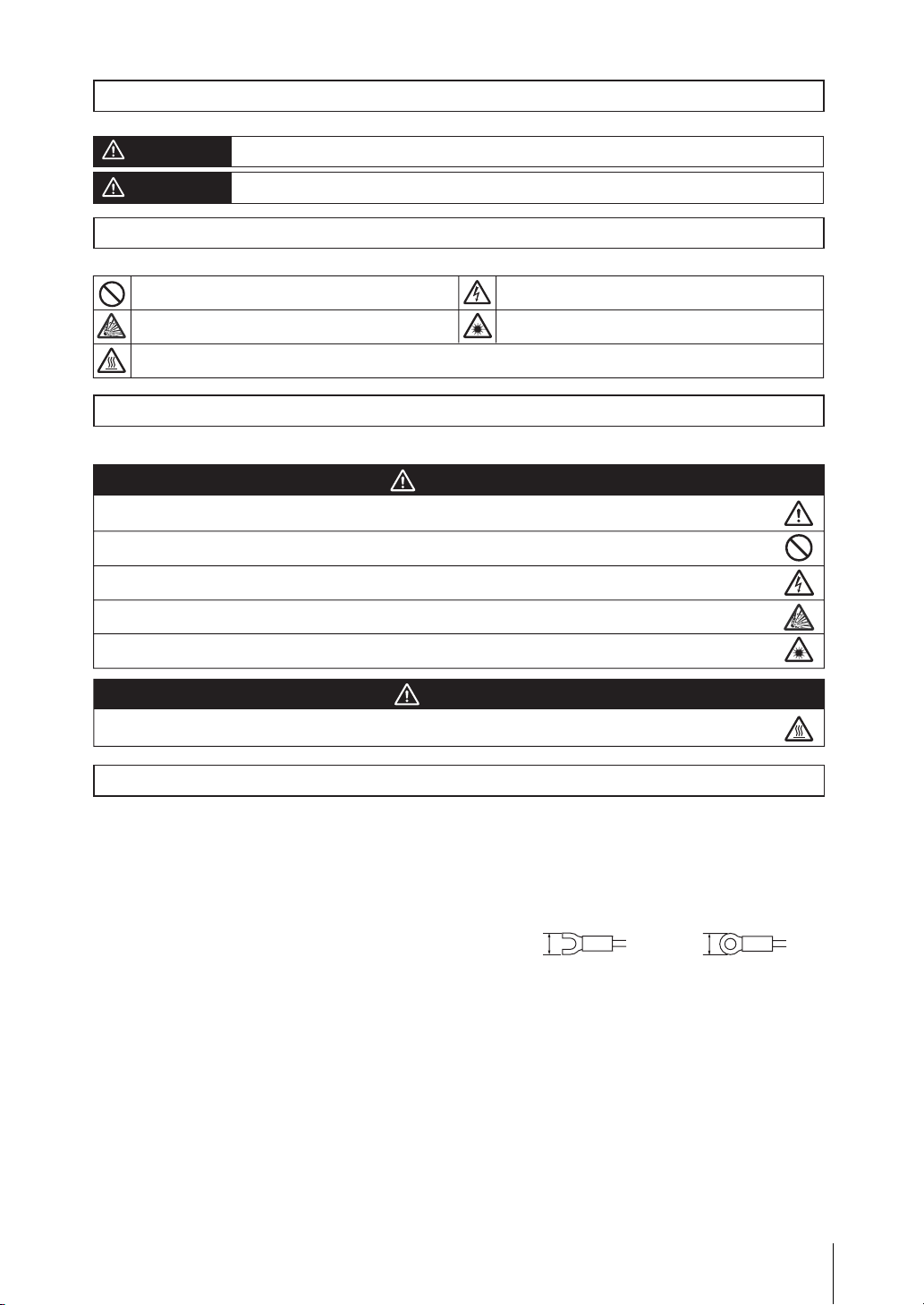
• Use a power supply cable and crimp terminals of the specified size. Do not simply connect the twisted ends of the wires directly to
the terminal block.
- Applicable wire size: 1.31 to 2.63 mm
- Terminal screw: M4
• Keep the power supply wires as short as possible (Max. 10 m).
• Use a DC power supply with safety measures against high-voltage spikes (safety extra low-voltage circuits on the secondary side).
• Ground the product’s ground terminal to less than 100 Ω.
• Use a grounding point that is as close as possible and keep the ground wire as short as possible.
• Wire the Controller to the ground with a separate ground wire. To avoid grounding problems, do not share the ground wire with any
other devices or wire the ground to the building's steel framing.
• Before turning on the power supply, confirm that the wiring is correct again.
Other
•
• Do not attempt to dismantle, repair, or modify the product.
• Should you notice any abnormalities, immediately stop use, turn OFF the power supply, and contact your OMRON representative.
• Do not touch fluorescent or halogen lights while the power is ON or immediately after the power is turned OFF.
• Dispose of this product as industrial waste.
Regulations and Standards
•
The Controller conforms to the following standards.
EC Directive 89/336/EEC (EMC)
EN standard (European Standard) EN61326
UL Standard UL61010-1
2
- Crimp terminals
8.5 mm max. 8.5 mm max.
2
Page 5

Precautions for Correct Use
Installation Site
•
Install the product in a place that meets the following conditions:
• Surrounding temperature of 0 to +50 °C
• No rapid changes in temperature (place where dew does not form)
• Relative humidity of between 35 to 85 %
• No presence of corrosive or flammable gases
• Place free of dust, salts and iron particles
• Place free of vibration and shock
• Place out of direct sunlight
• Place where it will not come into contact with water, oils or chemicals
Orientation of Product
•
To improve heat dissipation, install the product in the
following orientation only.
Ambient Temperature
•
•
Maintain a minimum clearance of 50 mm above and below the
controller to improve air circulation. A minimum clearance of
10 mm between other devices must also be maintained on the
right and left sides of the product. However, if the adjacent
devices do not generate heat, provide at least 50 mm of
clearance from the top of the Controller. For the clearance at
the bottom and sides, follow the mounting method.
• Do not install the product immediately above significant
heat sources, such as heaters, transformers, or
large-capacity resistors.
• Do not let the ambient temperature exceed 50 °C (122 °F).
• Provide a forced-air fan cooling or air conditioning if the
ambient temperature is near 50 °C (122 °F) so that the
ambient temperature never exceeds 50 °C (122 °F).
Noise Resistance
•
• Do not install the product in a cabinet containing
high-voltage equipment.
• Do not install the product within 200 mm of power cables.
Component Installation and Handling
•
• OMRON Components
Use only the camera and cables designed specifically for the product.
Failure to observe this may result in malfunction or damage of the product.
• Connecting/Disconnecting Camera and Cables
Always turn OFF the Controller’s power before connecting or disconnecting a camera
or cable.
• Touching Signal Lines
To prevent damage from static electricity, use a wrist strap or another device for
preventing electrostatic discharges when touching terminals or signal lines in
connectors.
• Handling a USB Memory
To remove a USB memory, make sure that data is not being read or written to it.
The LED on the USB memory flashes while data is being read or written, so make sure that it is lit steadily before removing the
memory.
• Turning OFF the Power
Do not turn OFF the power while a message is being displayed indicating that processing is being performed. Data in memory will
be corrupted, and the product may not operate correctly the next time it is started.
• Using the RESET Signal
Do not use the RESET input immediately after power is turned ON. When using the RESET input to synchronize startup timing,
wait at least 15 second after the Controller’s power supply is turned ON before turning ON the RESET signal.
Maintenance
•
Turn OFF the power and take safety precautions before conducting inspections. Electrical shock can result from attempting safety
inspections with the power turned ON.
• Clean the lens with a lens-cleaning cloth or air brush.
• Lightly wipe off dirt with a soft cloth.
• Dirt on the CCD must be removed using an air brush.
• Do not use thinners or benzene.
LCD integrated type
•
Box type
•
Do not install in this orientation.
To reserve ventilation path,
the feet must be mounted
to the side panel that is
positioned at the base.
Do not install in this orientation.
Confirming Package Contents
• Controller
• Instruction Manual (this manual)
• Booklet (“Please Read First”)
• Mounting bracket (for panel)
• Touch pen
Qty.: 1
Qty.: 1
Qty.: 1
Qty.: 6 * Supplied with the LCD integrated type only.
Qty.: 1 * Supplied with the LCD integrated type only
(provided inside the controller).
3
Page 6

Basic Configuration
* Items indicated with an asterisk are dedicated items, and cannot be substituted.
*
Controller
Use the monitor to check images and display the condition-setting
menus. The Controller performs the image processing specified by
the user settings and outputs the measurement results.
LCD integrated type FZ2-300/FZ2-305
FZ2-500/FZ2-505
*
Camera cable
Front view
Touch pen (standard accessory)
Right-side view
Camera cable
FZ-VS (2 m, 5 m, 10 m)
Elastic camera cable
FZ-VSB (2 m, 5 m, 10 m)
Right angle camera cable
FZ-VSL (2 m, 5 m, 10 m)
*
Controller
The Controlle r perform s the image
processing specified by the user settings
and outputs the measurement results.
Box type FZ2-350/FZ2-355
FZ2-550/FZ2-555
*
LCD monitor
Use the monitor to check images
and displa y the condition-settin g
menus.
FZ-M08 (8.4-inch)
*
Monitor cable
FZ-VM (2 m, 5 m)
*
Detects workpieces as images.
Intelligent camera
FZ-SLC15/FZ-SLC100
Camera
Automatic focus camera
㪝㪱㪄㪪㪱㪚㪈㪌㪆㪝㪱㪄㪪㪱㪚㪈㪇㪇
Power Supply
Recommended Model
By OMRON Corporation
S8VS-12024
Peripheral Device
*
Standalone camera FZ-SC/FZ-S
FZ-SC2M/FZ-S2M
USB memory
FZ-MEM256
Input Device
Mouse, track ball
(Commercially available USB devices)
*FZ-SC2M/FZ-S2M camera can be connected only with FZ2-50_ and FZ2-55_ controller.
4
Page 7

Component Names and Functions
LCD integrated type FZ2-300/FZ2-305/FZ2-500/FZ2-505
•
Left-side view Right-side view
6
7
Power/
ground terminal
1
POWER LED
2
RUN LED
3
ERROR LED
Box type FZ2-350/FZ2-355/FZ2-550/FZ2-555
•
5
Camera connector
11
Ethernet connector
8
Monitor connector (analog RGB)
Front view
10
USB connector
12
Touch pen (holder)
9
RS-232C/RS-422
connector
4
I/O connector
(control lines, data lines)
Monitor connector
8
(analog RGB)
11
Ethernet connector
Camera connector
5
10
USB connector
1
POWER LED
RUN LED
2
3
ERROR LED
10
USB connector
6
7
Power/ground terminal
9
4
I/O connector (control lines, data lines)
1
Lit while power is ON.
2
Lit while the controller is in Run Mode.
3
Lit when an error has occurred.
4
Connect the controller to external devices such as a sync sensor and PLC.
5
Connect cameras.
6
Connect a DC power supply. Wire the power supply unit independently
of other devices. After wiring, replace the terminal cover.
Power Supply and Wiring p.3
7
Connect the ground wire. Make sure that the controller is grounded with a
RS-232C/RS-422 connector
Power Supply Wiring
24VDC
+
–
separate ground wire.
8
Connect a monitor.
9
Connect an external device such as a personal computer or PLC.
10
Connect a track ball, mouse and USB memory. A total of four USB ports are provided and any of them can be
used. However, when connecting two or more USB memories, do not connect them to adjacent ports. Doing so
may cause the USB memories to come into contact, resulting in malfunction or damage.
• The following items can be connected to USB ports. • Commercially available track ball and mouse • USB memory
• Never insert/remove USB devices during measurement. Doing so may affect measurement time.
11
Connect the controller to a personal computer.
12
A touch pen is stored. (Provided with the LCD integrated type only)
• The touch pen must be stored so that the pen tip faces to the right when viewed toward the controller.
• To remove the touch pen, push the left side (handle) of the pen to the rear. The pen
hold and remove the pen.
’s right side (pen tip) will pop out, so
5
Page 8

Parallel Interface
NPN I/O type FZ2-300/FZ2-350/FZ2-500/FZ2-550
Internal Specifications
•
[Input] signals: RESET, DI0 to DI7, DSA
Input voltage
ON current *1
ON voltage *1
OFF current *2
OFF voltage *2
ON delay
OFF delay
Internal circuit
12 to 24 V DC ±10 %
5 mA min.
8.8 V min.
0.5 mA max.
1.1V max.
5 ms max.
0.7 ms max.
COM IN
[Input] signals: STEP
Input voltage
ON current *1
ON voltage *1
OFF current *2
OFF voltage *2
ON delay
OFF delay
Internal circuit
12 to 24 V DC ±10 %
5 mA min.
8.8 V min.
0.5 mA max.
0.8 V max.
0.1 ms max.
0.1 ms max.
COM IN
Input terminal
*1 ON current/ON voltage
This refers to the current or voltage values needed to shift from the OFF → ON state. The ON voltage value is the potential
difference between each of the input terminals and COM IN.
*2 OFF current/OFF voltage
This refers to the current or voltage values needed to shift from the ON → OFF state. The OFF voltage value is the potential
difference between each of the input terminals and COM IN.
[Output] signals:
BUSY, RUN, OR, GATE, ERROR,
[Output] signals: When STGOUT0 and 1 are not used,
DO0-15, READY
Output voltage
Load current
ON residual voltage
OFF leakage current
Internal circuit
I/O Connector
•
No. Wire color
Signal name
A1
COMIN
A2
(Open)
A3
(Open)
A4
(Open)
A5
(Open)
A6
DI1
A7
DI3
A8
DI5
A9
DI7
A10
STGOUT1
A11
STGOUT3
A12
ERROR
A13
COMOUT1
A14
(Open)
A15
(Open)
A16
(Open)
A17
COMOUT2
A18
DO1
A19
DO3
A20
DO5
A21
DO7
A22
DO9
A23
DO11
A24
DO13
A25
COMOUT3
•Handling the output common terminals
COMOUT1: STGOUT0 to 3, RUN, ERROR, BUSY, OR, GATE COMOUT2: READY, DO0 to 7 COMOUT3: DO8 to 15
*1 This is a signal that is used when the strobe device is connected to the Controller.
12 to 24 V DC ±10 %
45 mA max.
2 V max.
0.2 mA max.
Mark (red)
Orange
Gray
White
Yellow
Pink
Orange
Gray
White
Yellow
Pink
Orange
Gray
White
Yellow
Pink
Orange
Gray
White
Yellow
Pink
Orange
Gray
White
Yellow
Pink
Output terminal
Load
COM OUT
Common for input signals
(Leave open.)
(Leave open.)
(Leave open.)
(Leave open.)
Command inputs
Strobe trigger output (*1)
Strobe trigger output (*1)
ON when there is an error.
Common for control signals
(Leave open.)
(Leave open.)
(Leave open.)
Common for input signals
Data output
Common for input signals
Function
Output voltage
Load current
ON residual voltage
OFF leakage current
Internal circuit
No.
Signal name
RESET
B1
(Open)
B2
(Open)
B3
STEP
B4
DSA
B5
DI0
B6
DI2
B7
DI4
B8
DI6
B9
STGOUT0
B10
STGOUT2
B11
RUN
B12
BUSY
B13
GATE
B14
OR
B15
READY
B16
DO0
B17
DO2
B18
DO4
B19
DO6
B20
DO8
B21
DO10
B22
DO12
B23
DO14
B24
DO15
B25
Wire color
Orange
Gray
White
Yellow
Pink
Orange
Gray
White
Yellow
Pink
Orange
Gray
White
Yellow
Pink
Orange
Gray
White
Yellow
Pink
Orange
Gray
White
Yellow
Pink
Input terminal
connect the COM IN terminal.
12 to 24 V DC ±10 %
45 mA max.
2 V max.
0.2 mA max.
COM IN
Output terminal
COM OUT
Mark (red)
Controller restart
(Leave open.)
(Leave open.)
Measurement trigger input
Data send request signal
Command inputs
Strobe trigger output (*1)
Strobe trigger output (*1)
ON while in Run mode
ON during processing
ON for the set output time
Overall judgment result
ON when image input is allowed
Data output
Function
Load
6
Page 9

Parallel Interface
PNP I/O type FZ2-305/FZ2-355/FZ2-505/FZ2-555
Internal Specifications
•
[Input] signals: RESET, DI0 to DI7, DSA
Input voltage
ON current *1
ON voltage *1
OFF current *2
OFF voltage *2
ON delay
OFF delay
Internal circuit
12 to 24 V DC ±10 %
5 mA min.
8.8 V min.
0.5 mA max.
1.1V max.
5 ms max.
0.7 ms max.
Input terminal
[Input] signals: STEP
Input voltage
ON current *1
ON voltage *1
OFF current *2
OFF voltage *2
ON delay
OFF delay
Internal circuit
12 to 24 V DC ±10 %
5 mA min.
8.8 V min.
0.5 mA max.
0.8 V max.
0.1 ms max.
0.1 ms max.
Input terminal
COM IN
*1 ON current/ON voltage
This refers to the current or voltage values needed to shift from the OFF → ON state. The ON voltage value is the potential
difference between each of the input terminals and COM IN.
*2 OFF current/OFF voltage
This refers to the current or voltage values needed to shift from the ON → OFF state. The OFF voltage value is the potential
difference between each of the input terminals and COM IN.
[Output] signals:
BUSY, RUN, OR, GATE, ERROR,
[Output] signals: When STGOUT0 and 1 are not used,
DO0-15, READY
Output voltage
Load current
ON residual voltage
OFF leakage current
Internal circuit
I/O Connector
•
No. Wire color
Signal name
12 to 24 V DC ±10 %
45 mA max.
2 V max.
0.2 mA max.
Mark (red)
Function
COM OUT
Load
Output terminal
Output voltage
Load current
ON residual voltage
OFF leakage current
Internal circuit
No. Wire color
Signal name
COM IN
connect the COM IN terminal.
12 to 24 V DC ±10 %
45 mA max.
2 V max.
0.2 mA max.
Mark (red)
Function
COM OUT
Output terminal
Load
COM IN
㩷
I/O Connector wiring is the same as NPN I/O type.
7
Page 10

Connector
•
Connect the optional parallel I/O cable (FZ-VP).
Box type
LCD integrated type
Serial Interface
Connector
•
Pin No.
Signal name
1
SDB(+)
2
SD/SDA(-)
3
RD/RDA(-)
4
RDB(+)
5
6
7
8
9
NC
NC
NC
NC
GND
Use a compatible connector.
• Recommended items
Manufacturer Model
Plug
OMRON Corporation
Hood
OMRON Corporation
Function
For RS-422
For RS-232C/RS-422
For RS-232C/RS-422
For RS-422
Not connected
Not connected
Not connected
Not connected
Signal ground
XM2A-0901
XM2S-0911
FZ-VP (2 m, 5 m)
Wire Color
No. mark
Wiring
•
The maximum cable length is 15 m.
• RS-232C
Controller
Signal name
SD
RD
GND
Pin No.
2
3
9
Use a shielded cable.
External device to be connected
Pin No.
*
*
*
RS/CS control cannot be used.
• RS-422
Controller
Signal name
SDB(+)
SDA(-)
RDA(-)
RDB(+)
Pin numbers will depend on the external device being connected. Refer
to the manual for the personal computer or PLC being connected.
Pin No.
1
2
3
4
Use a shielded cable.
External device to be connected
Pin No.
*
*
*
*
Signal name
SD
RD
GND
Signal name
SDA(-)
SDB(+)
RDB(+)
RDA(-)
Connection Method
•
Align the connector with the socket and
press it straight into place, then fix it with
the screws on both sides of the connector.
Turn OFF the power supply before connecting or
disconnecting a Parallel I/O Cable. Peripheral
devices may be damaged if the cable is connected
or disconnected with the power ON.
LCD integrated type
Box type
8
Page 11

Mounting
LCD integrated type
•
• Panel mounting
1
Make a mount hole on the panel.
Panel thickness range: 1.6 to 4.8 mm
Panel material: Metal (iron, aluminum
or stainless)
2
Insert the LCD integrated controller
into the hole, from the front panel.
3
Use the bracket (supplied with the
product) to secure the controller
and the panel.
Tightening torque: 0.5 to 0.6 Nm
0
1
+
247
Top face
Bottom face
297
1
+
0
(Unit: mm)
* No burr allowed
• Mounting the controller to the optional
desktop stand.
The controller can be placed on
a desk by attaching the optional
desktop stand (FZ-DS) to the
rear of the controller.
* For details, refer to the instruction
manual of the desktop stand.
Box type
•
• Side mounting • Bottom mounting
(17)
4-M4 Depth 6
80 ± 0.25
126 ± 0.25
(11)
• Mounting the controller to the optional
VESA attachment unit.
VESA-compatible mounting of
the controller is possible by
attaching the optional VESA
attachment unit (FZ-VESA) to
the rear of the controller.
* For details, refer to the instruction
manual of the VESA attachment
unit.
* When mounting the controller on its bottom, it must be fixed
without removing the feet to reserve ventilation path.
4-M4 Depth 6
(13)
0.25
±
64
(26)
100
± 0.25
4-
( )
39
20
(18)
0.25
±
54
9
Page 12

Controller External Dimensions
LCD integrated type FZ2-300/FZ2-305/FZ2-500/FZ2-505
•
Depth 6
4-M3
7
()
120 120
20
130
(Unit: mm)
()28.412.8 10
+
–
33
260
165
83
()
68
308
Box type FZ2-350/FZ2-355/FZ2-550/FZ2-555
•
90
4-M4 Depth 6
17 80
246
7
110
163.5
()
68
()
6
296
20
120 120
()
68
6
80 17
(Unit: mm)
4-M4 Depth 6
190
11 126
8
4-M4 Depth 6
13
64
126
+
–
33
11
()
6.8
11.5
15.45
()
20
4-
1854
()
100
26
39
10
Page 13

Controller Specifications
Power supply voltage
Current consumption
Insulation resistance
Dielectric strength
Leakage current
Noise resistance
Vibration resistance
Shock resistance
Ambient temperature range
Ambient humidity range
General specifications
Ambient environment
Ground
Degree of protection
Environmental conditions
(according to IEC61010-1)
Case materials
Weight
 Loading...