

Page 1
Cat. No. Z275-E1-01
FZ2 Series
Vision Sensors
USER'S MANUAL
Page 2
FZ2 Series User's Manual
Vision Sensor
Rev.A
How This Manual Is Organized
This Manual includes tw
operations and settings of vision sensors, and "Processing Item List Manual", which
describes the setting options of each processing item.
Conventions Used in This Manual
Symbols
The symbols used in this manual have the following meanings.
Punctuation Marks
In this manual, Menu, among others, is defined as follows.
[ ] Menu indicates the name of menu or Processing item shown in the menu bar.
" " Item name indicates the item name displayed in the screen.
o manuals, "User's Manual", which describes the basic
Indicates the relevant operational precautions that must be
followed.
Indicates operation-related suggestions from OMRON.
Page 3

User's Manual
This manual describes the basic operations and all settings when using vision sensors.
This Manual includes two parts: Operation and Environment Settingas Parts. The
contents are shown as follows.
Operation Part
This part describes how to measure according to the workflow chapter by chapter.
First, prepare to measure by performing "Preparation"g"Design Contents to be
Measurement"g"Set up Contents to be Measurement".
Then, confirm whether or not to measure exactly against the expected objectives by
performing "Measurement Test"g"Adjusting Measurement Contents" repeatly.
Finally, perform "Actual Measurement"g"Verify Measurement Results".
In addition, this part also describes the operations of controller and how to utilize and
analyze the measurement results.
Environment Setting Part
This part describes the measurement environment (camera and lighting, etc.) and the
required system setting and configuration to facilitate the measurement.
In addition, this part also describes the required setting for outputting the measurement
results to external devices and how to store data.
For the Q&A and how to treat the encountered faults, see Appendix. Please read as
required.
Page 4
User's Manual
Operation Part
Operation Part
This part describes the operation flow from planning to actual measurement and result
verification.
Before Operation
Design
Preparation
Setting up Scene (Measurement Flow)
Test Measurement/Re-measurement/Adjustment
Starting Operation
Utilizing/Analyzing Measured Data
Page 5
Chapter 1 - Before Operation
This chapter describes fundamental operations and designations of components of this
product.
Operation Flow
Screens/Windows
Input Operation
Inputting a Value
Inputting a Text
Selecting Files and Folders
Operations of ProcItem Setting Window
Setting Figures
Saving Settings and Powering Off
Page 6
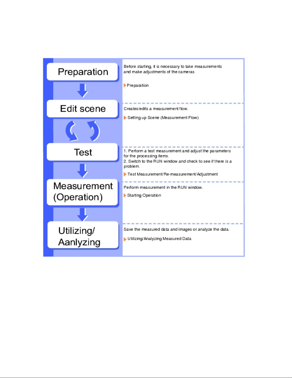
Operation Flow
Here describes the operation flow.
Page 7
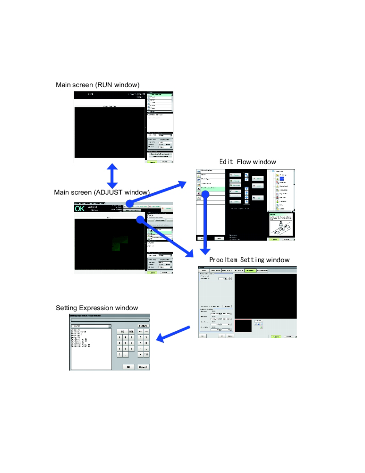
Screens/Windows
The screen varies with the operating state. Some typical interface structures and various
buttons are functionally described hereto.
Page 8
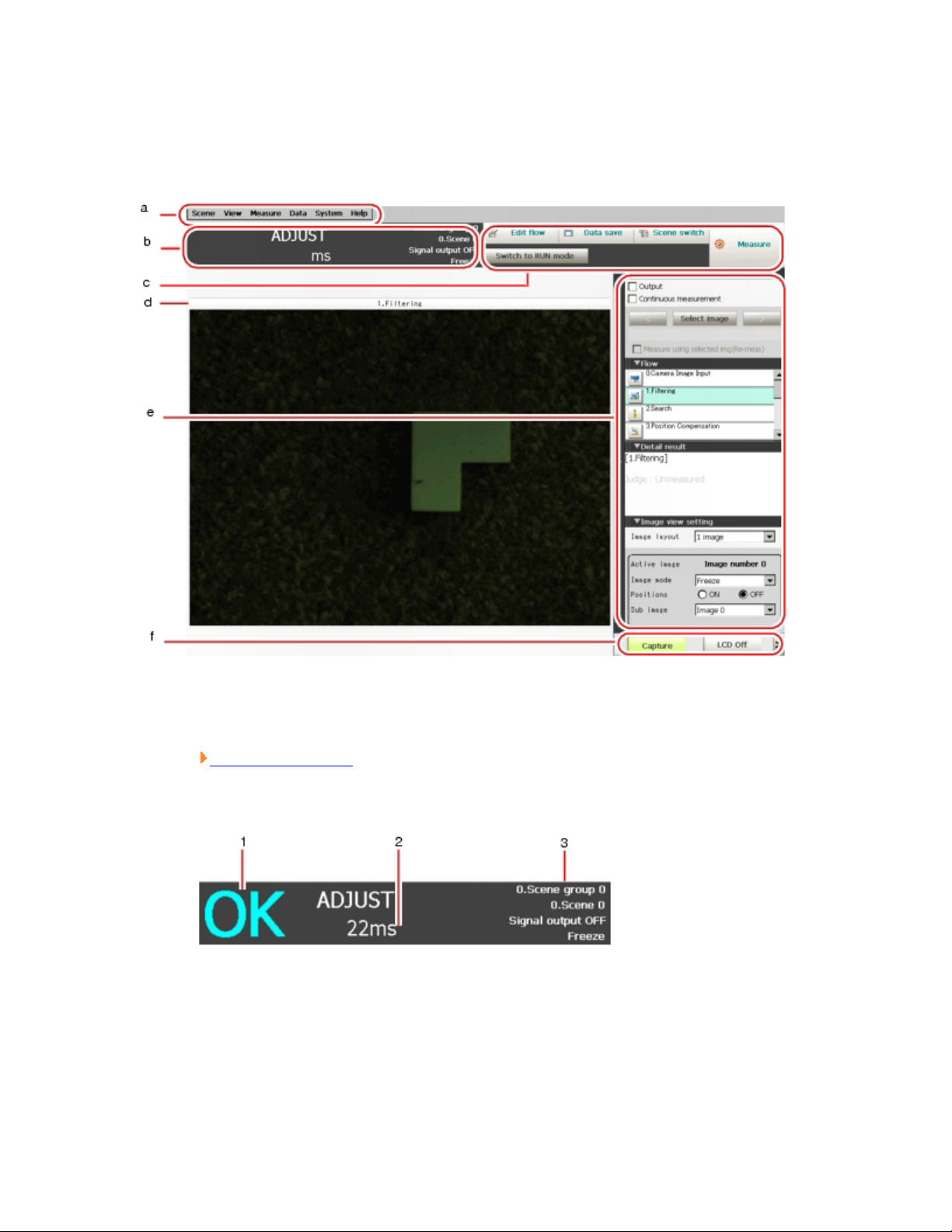
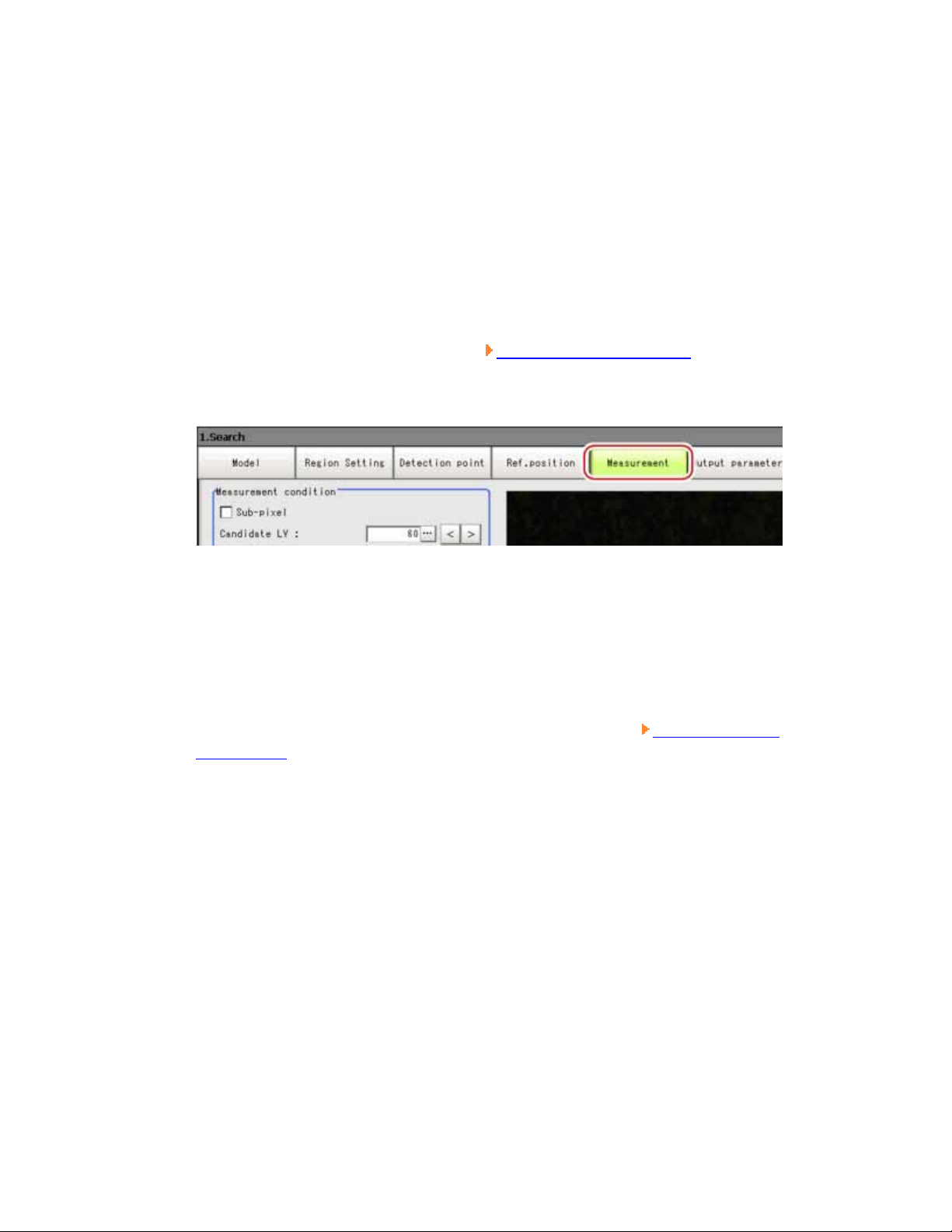
Main Screen (ADJUST window)
The screen is used for carrying out measurement, from which measurement results can be
verified.
1. Menu bar
To select the menu used for measurement-related operation or setting.
Main Screen Menu
2. "Measurement information display" area
1. Overall judgement
Displays the result of the overall judgement of a scene ([OK]/[NG]).
The judgement result for each processing item is displayed in each flow
unit of the "Control" area.
2. Process time
Page 9

Displays the time required for the measurement process.
3. Status display
Displays the scene group number, the scene number, the external output
status, and the image mode for the currently displayed content.
3. Toolbar
Some common functions are reserved in Toolbar.
o Edit flow
Displays the Edit Flow window. In the displayed window, you can add,
delete, or edit processing units.
What is Scene
Edit Flow Window
o Data save
Setting data is saved into flash memory in the controller. Scene group data
can also be saved to USB memory. Modified settings must be saved.
Saving Setting Data in the Controller's Memory [Data save]
o Scene switch
To switch a scene group or a scene.
Changing Steps (Scene Switch)
o Measure/Stop meas.
Starts/stops measurement. The measurement is performed in accordance
with [Test measurement] settings in the "Control" area.
Test Measurement before Actual Operation
o Switch to RUN mode
Switches the display to the RUN window.
Edit Flow Window
4. "Image display" area
Page 10
Displays the measured image.
1. ProcItem setting button
Displays the name of the processing item for the currently selected
processing unit. When tapping the button, the ProcItem Setting window is
displayed.
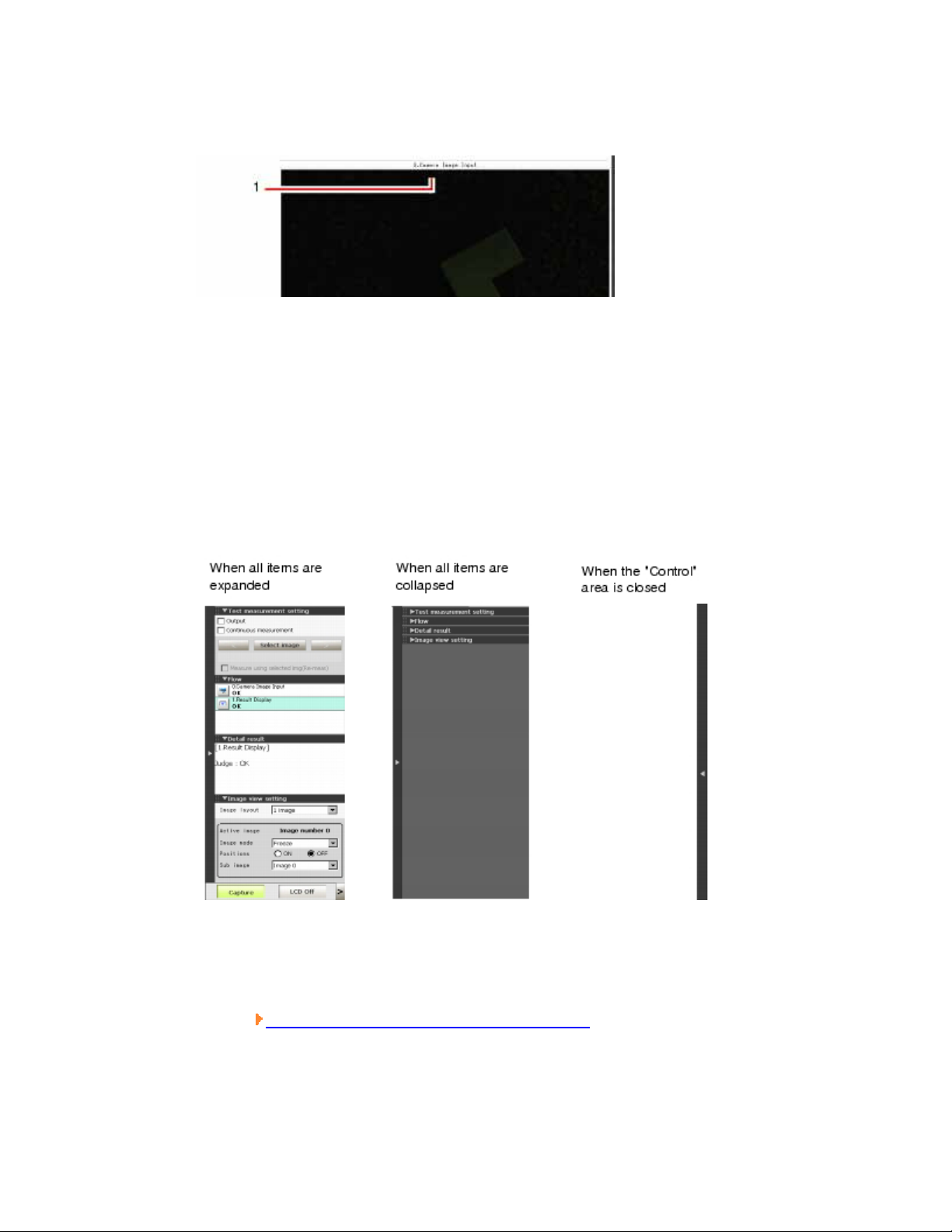
5. "Control" area
Displays "Test measurement setting", "Flow", "Detail result", and "Image view
setting". You can expand or collapse each item by tapping its panel.
o Test measurement setting
Sets up test measurement or re-measurement using a previously input
image.
Test Measurement before Actual Operation
o Flow
Page 11
Displays the measurement flow for the scene used for measurement. Tap a
button for each unit to display the ProcItem Setting window and change
the processing unit settings.
Operations of ProcItem Setting Window
The size of the processing unit buttons can be switched by tapping
[Display] - [Display the enlarged measurement flow].
o Detail result
Displays with the text, detailed measurement results of the processing
units selected in the measurement flow.
o Image view setting
Specifies the display settings for the "Image display" area.
Display Setting
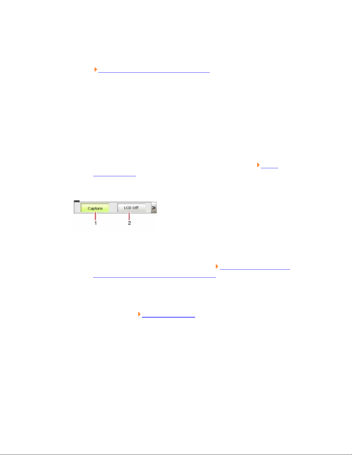
6. Measurement Manager bar
1. [Capture]
Saves the content displayed on the monitor as an image.
For settings and operation of [Capture], see Setting the Destination to
Save Capture Image [Screen capture setting].
2. [LCD Off]
Turns off the power of the LCD monitor. For settings and operation of
[LCD Off], see Powering Off LCD.
Image
Page 12
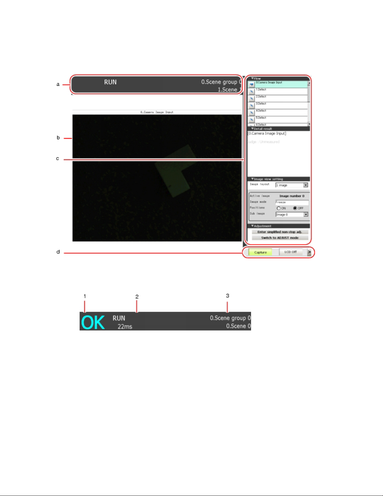
Main Screen (RUN window)
This is the window used during operation.
1. "Measurement information display" area
1. Overall judgement
Displays the result of the overall judgement of a scene ([OK]/[NG]).
The judgement result for each processing item is displayed in each flow
unit of the "Control" area.
2. Disp mode
The current image mode, [Through], [Freeze], or [Last NG], is displayed.
3. Scene group name and Scene name
Page 13
Displays the scene group number and the scene number.
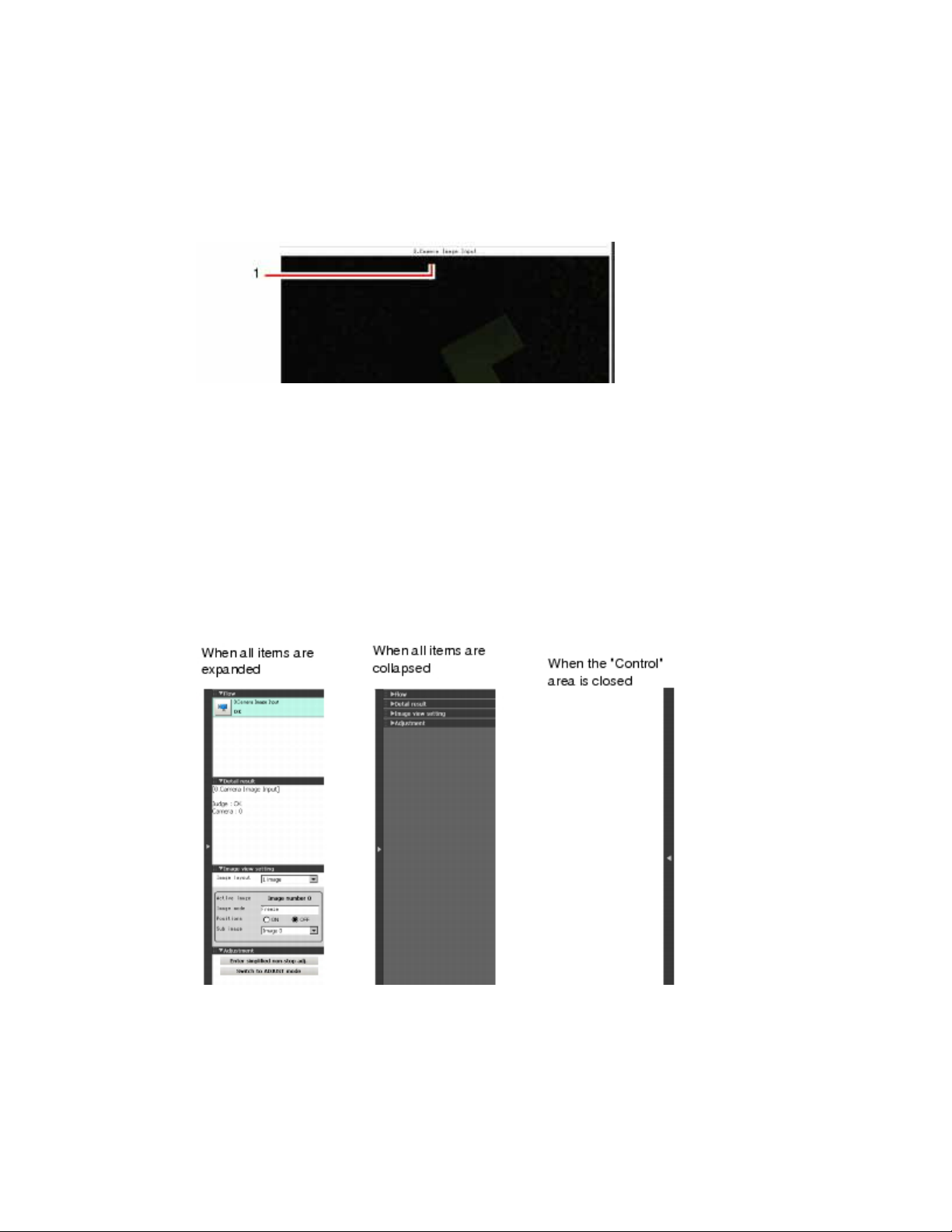
2. "Image display" area
Displays the measured image.
1. ProcItem setting button
Displays the name of the processing item for the currently selected
processing unit. If this button is tapped during simplified non-stop
adjustment, the ProcItem Setting window is displayed.
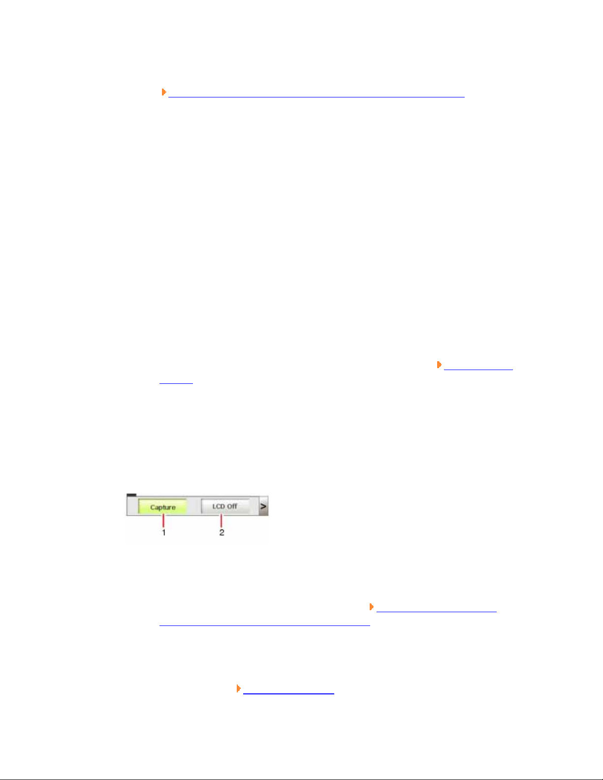
3. "Control" area
Displays "Flow", "Detail result", "Image view setting", and "Adjustment". You
can expand or collapse each item by tapping its panel.
o Flow
Displays the measurement flow for the scene used for measurement. When
a simple non-stop adjustment is executed, if you tap a button (icon) of
each unit (icon), judgement conditions are displayed in of the ProcItem
Page 14
Setting window, and the settings can be changed.
Changing Judgement Condition of a Unit during Measurement
Important
o When simplified non-stop adjustment is not being performed, the
ProcItem Setting window is not displayed even if a button for a processing
unit is tapped.
In the RUN window, the size of processing unit buttons cannot be changed. To
change the size of processing unit buttons of the RUN window, set the size of
buttons in the ADJUST window, select "Data save", and then switch back to the
RUN window.
o Detail result
Displays with the text, detailed measurement results of the processing
units selected in the measurement flow.
o Image view setting
Specifies the display settings for the "Image display" area.
Setting
o Adjustment
Starts and stops simplified non-stop adjustment, and switches to the
ADJUST window.
4. Measurement Manager bar
1. [Capture]
Saves the content displayed on the monitor as an image.
For settings and operation of [Capture], see Setting the Destination to
Save Capture Image [Screen capture setting].
2. [LCD Off]
Image Display
Turns off the power of the LCD monitor. For settings and operation of
[LCD Off], see Powering Off LCD.
Page 15
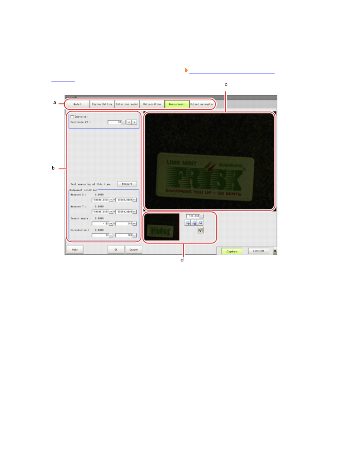
ProcItem Setting Window
This window is used to set the Measurement parameters and judgement conditions, etc,
of Processing Item. For window operations, see
Window.
Operations of ProcItem Setting
1. "Item tab" area
Displays detailed setting items as tabs, for the processing unit selected in the Edit
Flow window or in [Flow] of the "Control" area on the Main screen.
2. "Detail" area
Displays and changes settings for the detailed setting item selected in the "Item
tab" area.
3. "Image display" area
To display the Coordinate, figure and images captured from camera, etc.
4. "Zoom browser" area
Page 16
Zooms in and out of the displayed image.
Using Zoom Function
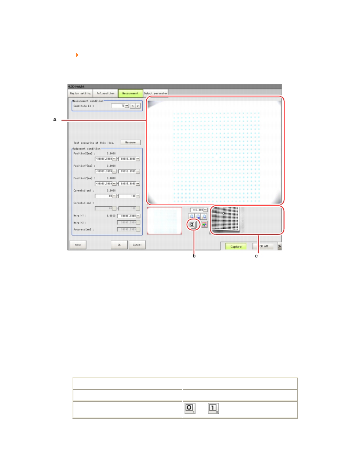
3D Processing Item Window
1. "Image display" area
Displays the coordinates, figures and images captured from cameras, etc.
2. 3D camera switching button
When tapping the button, the camera image in the "Image display" area is
switched.
The button number indicates the camera image currently displayed in the "Image
display" area.
Depending on the camera used, the buttons will change as described below.
Table: 3D camera switching button
Camera number Buttons displayed
When using camera input 0 and 1.
and are switched.
Page 17
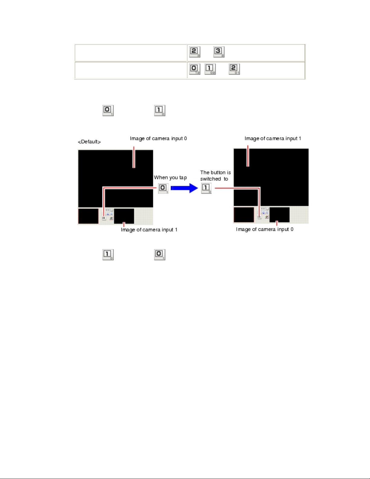
When using camera input 2 and 3.
and are switched.
When using camera input 0, 1, and 2.
Example) A display when camera input 0 and 1 are used.
Tapping switches it to , and the image of camera input 1 is displayed in
the "Image display" area.
, and are switched in order.
Tapping switches it to , and the image of camera input 0 is displayed in
the "Image display" area.
3. "Sub image" Area
A camera image other than the image displayed in the "Image display" area is
displayed.
Page 18
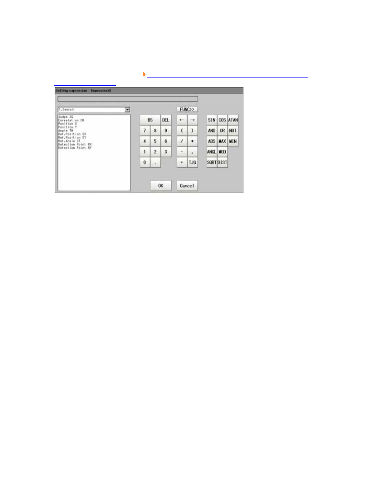
Setting Expression Window
This window is used for setting expressions for measurement. For the contents and
operation of this window, see
Expression Window".
Processing Items List Manual, "How to Display Setting
Page 19

Input Operation
This section describes the basic operations of input devices of this product.
Page 20
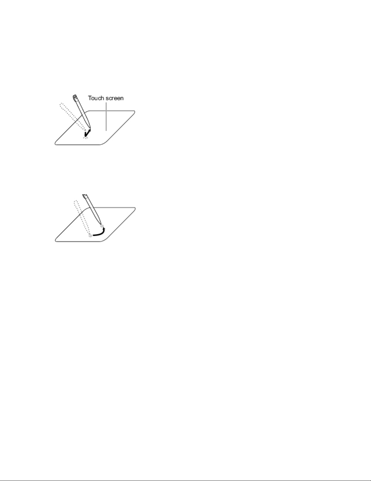
Operations of Touch Pen (for Users of Panel-type Controller)
The touch pen is used in the touch screen in either of the following ways.
Tapping
Touch the screen slightly with the touch pen, and then take off immediately in order to
select
Processing items.
Drag & Drop
Draw while tapping the screen slightly with the touch pen.
Important
For touch screen operation, the supplied touch pen must be used. Otherwise, the
touch screen would be damaged when using a pencil or a ballpoint pen.
In addition, delay may occur when tapping touch screen continuously and rapidly.
Page 21
Basic Operations of Mouse and Trackball (for Users of BOX-type
Controller)
Please use currently available mouse or trackball with USB interface.
(See the list for recommended products. Please refer to product catalogue.)
Note
Don't use the right mouse button, roller and other keys.
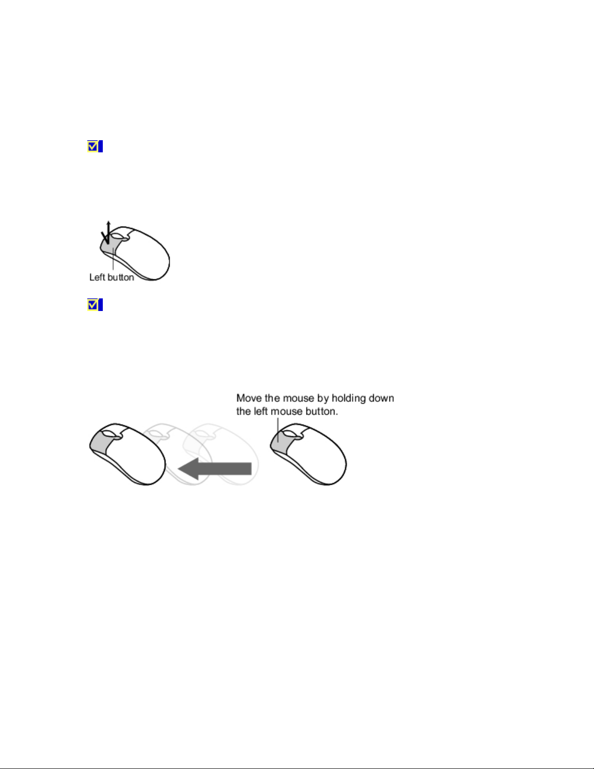
Tapping
Press the left mouse button to select Processing items.
Note
This document primarily describes the operation of "Tapping". If you use mouse
or trackball, "Tapping" is deemed to be "Clicking".
Drag & Drop
Move the mouse by holding down the left mouse button.
Page 22
Inputting a Value
This section describes how to input the data required for setting the Judgement conditions
and communication specifications. There are a few input ways according to different
settings.
Setting by drawing a figure (Setting the coordinates on the figure as values)
When carrying out "Model registration"/"Region" for specific Processing items,
visual operation is possible without considering the related value. For details, see
Setting Figures.
Specify values directly with the numeric keyboard
Used when the value to be inputted is specific.
Adjust values with [ ] and [ ] beside the numeric keyboard
Used to fine-tune the set values.
Set up values by dragging the slider
Dragging the slider on the screen allows to setting up values.
Here we'll describe how to use the numeric keyboard to set up values. For other methods,
refer to individual setting descriptions.
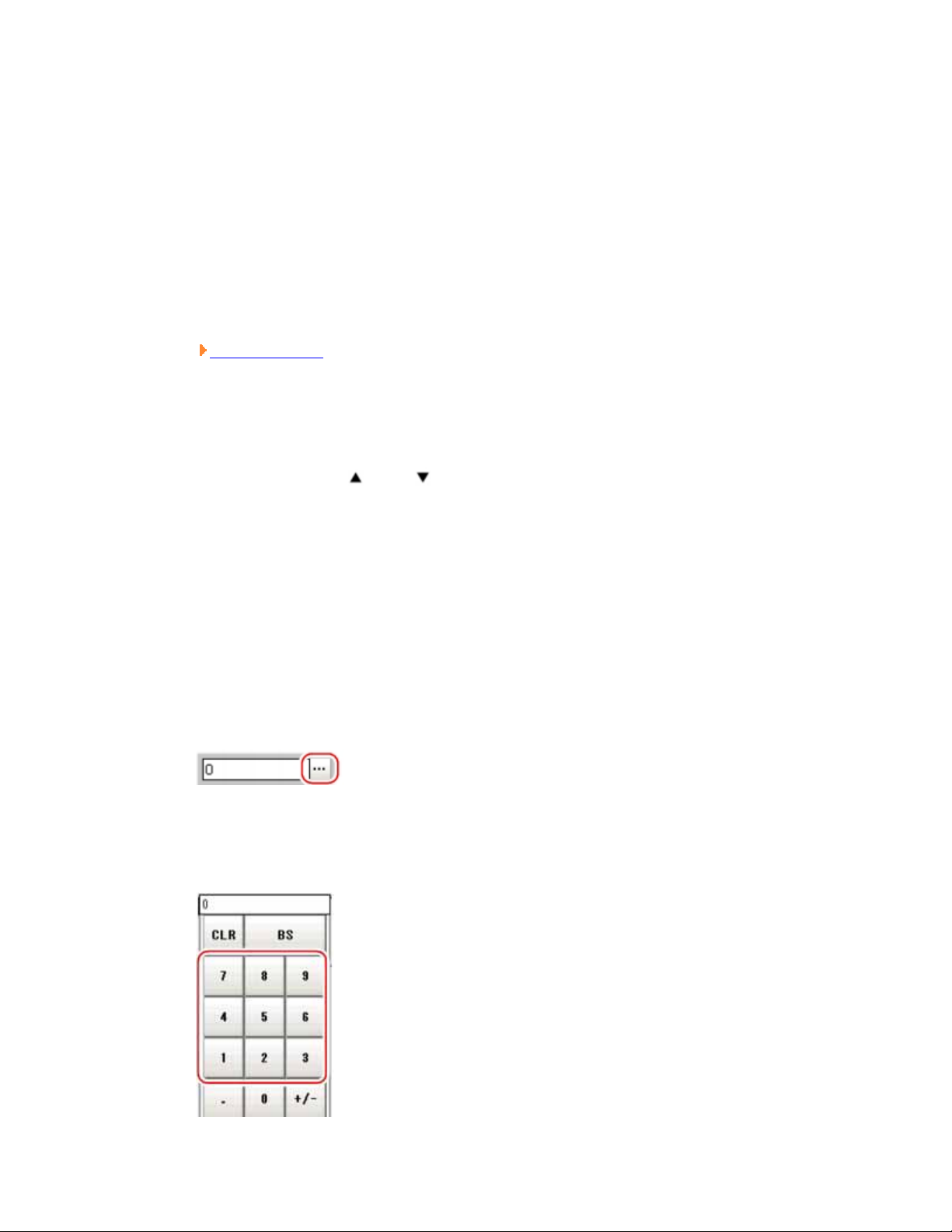
1. Tap the Processing item's [...] to specify values.
The numeric keyboard is displayed.
2. Tap numeric key to input value.
Page 23

The numerical value is input.
3. Tap [OK].
Verify the value, and close the numeric keyboard.
Page 24
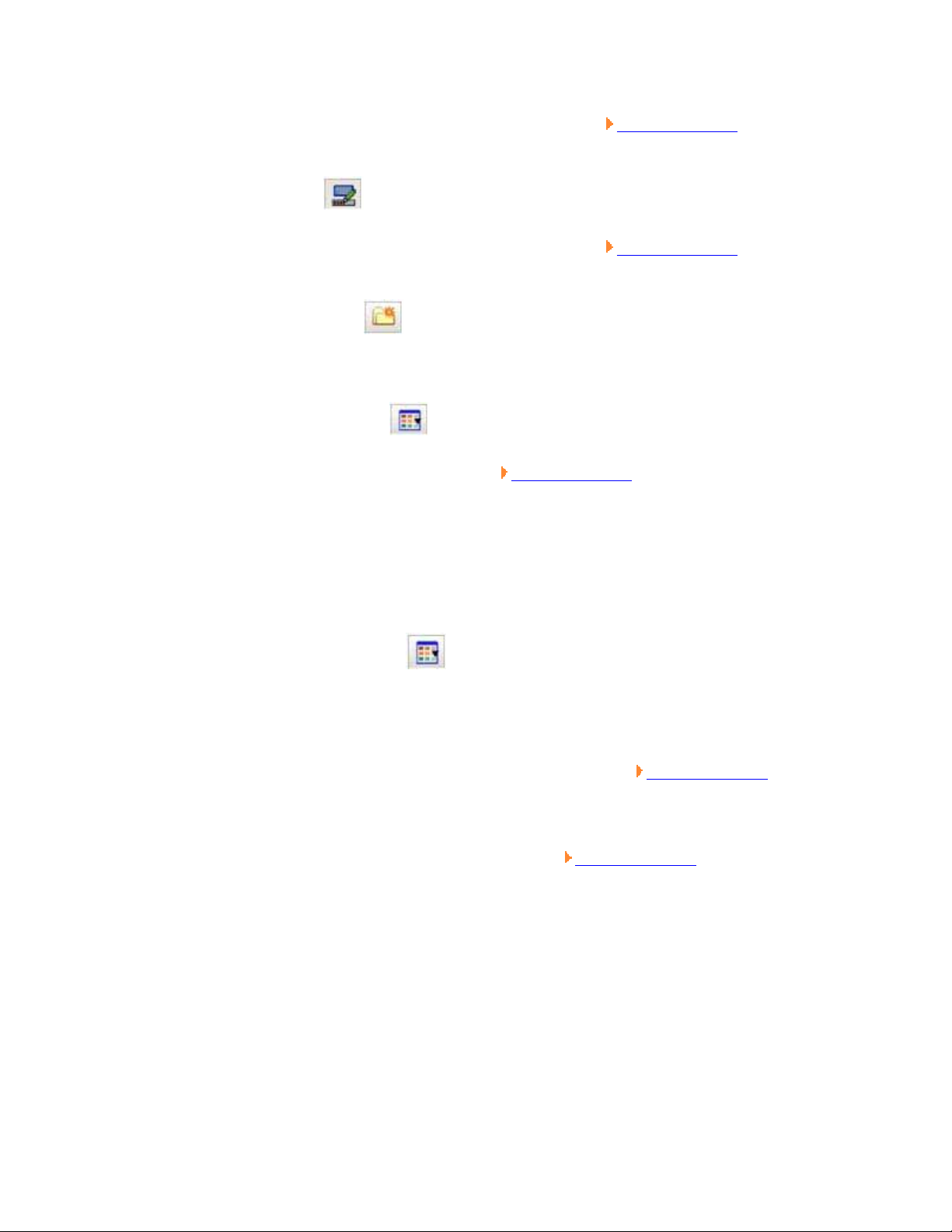
Inputting a Text
This section describes how to input File names and descriptive text.
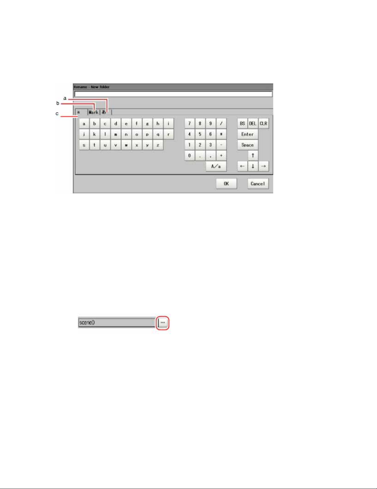
The following software keyboard is viewed in the input text screen.
1. Japanese input mode
2. Mark (One-byte Characters Input Mode)
3. a (Alphanumeric Characters Input Mode)
To toggle between uppercase and lowercase mode, tap "A/a". The initial state is
lowercase mode.
Operation Method
1. Tap [...] for the item to set a character string.
The software keyboard is displayed.
2. Choose your desired language from the tab.
3. Enter text and tap [OK].
The software keyboard is Closed.
Page 25
Selecting Files and Folders
This section describes how to select a destination folder for images captured from such
operations as saving data/load and re-measurement.
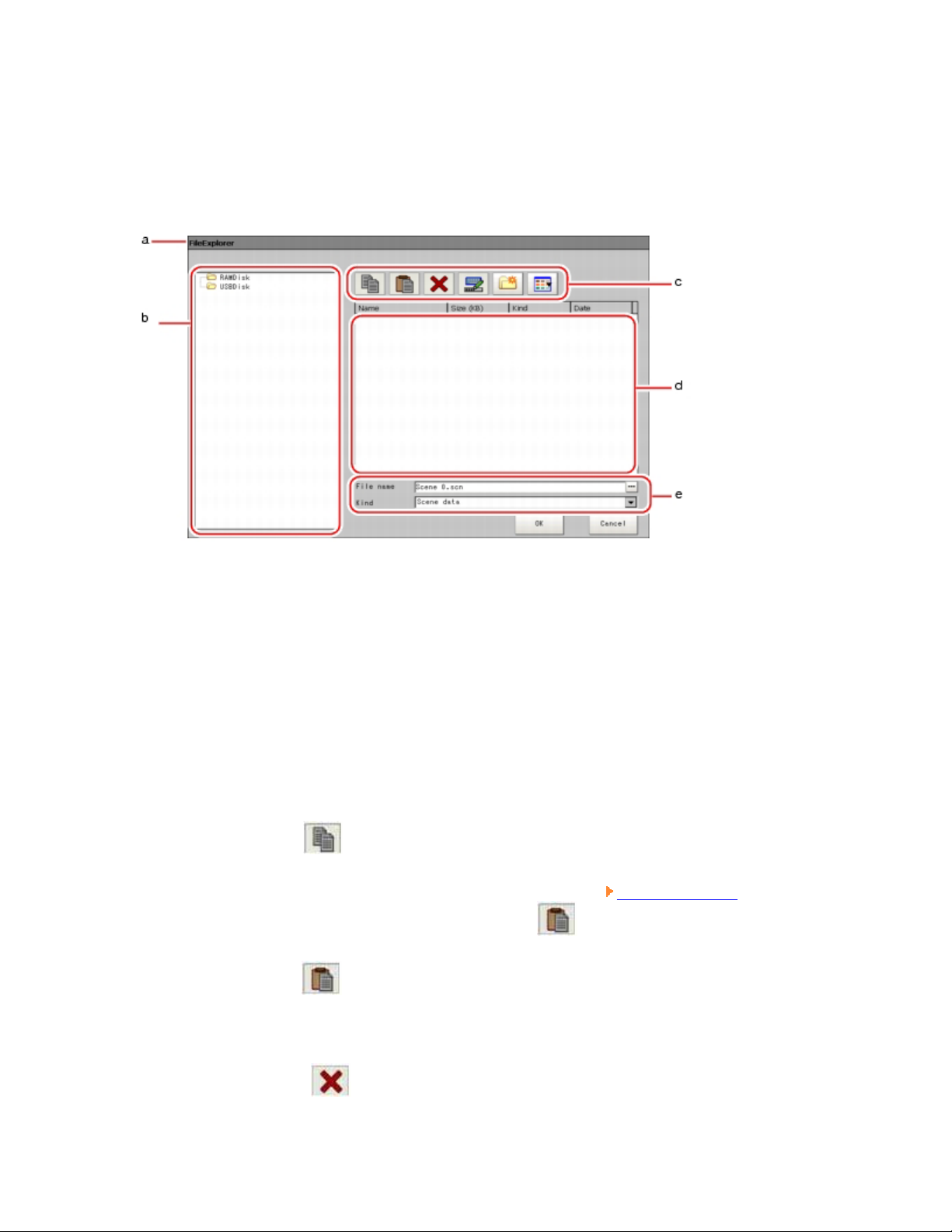
The following window will appear in File and Folder Selection window.
1. Window Title
When specifying a file, the title is "FileExplorer". When selecting a folder, the
title is "Select folder".
2. "Folder view" area
Lists folders on the RAM disk and folders in the mounted USB memory. At the
root of the tree, all accessible USB memory drives are displayed (ex. "USBDisk",
"USBDisk2").
3. Toolbar
o Copy ( )
Enabled when a folder or file is selected in the
tapping and copying, the Paste option
o Paste ( )
Enabled when performing copying. Paste copied files or folders.
"List view" area. After
will become enabled.
o Delete ( )
Page 26
Enabled when a folder or file is selected in the "List view" area. Tapping
allows to opening a window for you to confirm the deletion.
o Rename ( )
Enabled when a folder or file is selected in the
"List view" area. When
tapped, the Rename window is displayed.
o New a Folder ( )
Create a new folder.
o Toggle List View( )
Switches the display style of the
"List view" area.
4. "List view" area
To display the list of the files and folders contained in the folder which is selected
from the "Folders view" area.
In addition, when an extension name is selected from "Type", then only the files
with the selected extension name can be viewed. To change a viewed list, tap
"Toggle List View" button (
).
5. "File name view" area
o Name
To display the names of the files selected from the
o Type
Specifies the type of the file displayed in
"Scene data (*.scn)" and "System data (*.ini)".
"List view" area .
"List view" area, such as
Page 27
Available Operations in File Selection Window
This section describes available operations from the File Selection screen.
Note
When the target file is not viewed in the "List view" area, please check to ensure
that a file type is selected from the "Type".
Copying/Pasting a File or Folder
1. Tap a folder or file that you want to copy in the "List view" area.
A folder or a file is selected.
2. Tap "Copy" (
).
3. Select the destination folder, and tap "Paste" ( ).
Renaming a Folder or a File
1. From the "List view" area, tap the name of file or folder to be renamed.
The file or folder will be selected.
2. Tap "Rename" (
).
The software keyboard is displayed.
3. Enter a new name.
Page 28
How to input text: Inputting a Text
Note
When a file with the same name exists, a prompt will be viewed telling you that
you cannot select the name.
Deleting a Folder or a File
1. From the "List view" area, tap the name of file or folder to be selected.
The file or folder will be selected.
2. Tap [Delete] ( ).
A window will be viewed for your confirmation.
3. Tap [OK].
The selected file or folder will be deleted.
Page 29
Operations of ProcItem Setting Window
Detailed settings for each processing unit are set in the ProcItem Setting window. This
section explains basic common operations in the ProcItem Setting window.
1. Display the ProcItem Setting window.
The ProcItem Setting window can be displayed from the Main screen or the Edit
Flow window.
For the ProcItem Setting window, see ProcItem Setting Window.
2. Tap one of the setting items in the "Item tab" area.
The items displayed in the "Item tab" area vary depending on the processing item.
According to the item selected in the "Item tab" area, the displayed contents
change in the "Detail" area and the "Image display" area.
3. You can change parameters from the "Detail" area.
For more Details about the setting of Processing items, see
List Manual.
4. If necessary, repeat Steps 2 and 3.
5. Tap [OK].
The new settings are applied and the ProcItem Setting window closes.
Processing Items
Page 30
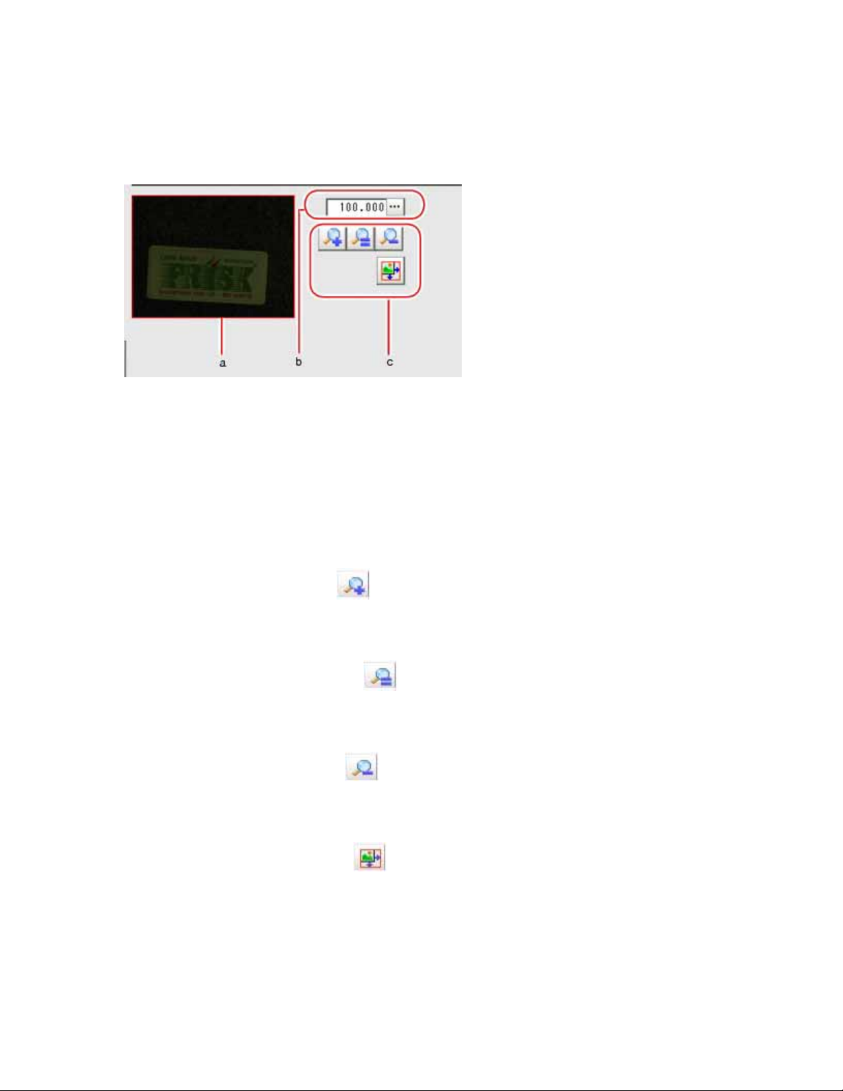
Using Zoom Function
Specifies the magnification settings of the displayed image in the ProcItem Setting
window.
1. Zoom browser
Indicates the zoomed area in the original image.
2. Magnification factor
Enters the magnification factor between 25% and 1600%.
3. Operation buttons
o Zoom-in button ( )
Enlarges the selected area two times.
o Original size button ( )
Displays the selected area in the original size.
o Zoom-out button ( )
Reduces the selected area by half.
o Full-screen button ( )
Displays the selected area in full screen mode.
Page 31

Setting Figures
This section describes how to set up objcets (figures and text) when registering models or
measurement regions.
The type and number of objects differ depending on different setting options. For the
available setting options, see Corresponding Image List of Processing Items and
Processing Items List Manual, "Processing item List".
Page 32

"Figure Setting" Area
Registers a figure when registering or setting a measurement region or model.
1. Figures
Lists the names of the registered objects. The figure at the bottom of the list is the
most foreground object. The upper place the object is listed in, the more
background it is displayed.
2. [Edit]
Used to edit a figure. The following figure editing tool is displayed.
Page 33

1. Drawing tool buttons
Sets up objects, such as figures and text. The number and type of the
objects available are different depending on the item to work with (ex.
"Result display", "Model", "Region setting"). For details, see
Corresponding Image List of Processing Items.
2. Object editing buttons
Buttons for editing objects
3. Details
Shows the details of the selected figure. Object coordinates or radius can
be specified. Tapping [ ] or [ ] will display the items currently not
displayed.
3. "Zoom browser" area
Magnifies the "Image display" area by the selected magnification factor.
Zoom Function
Using
Page 34

How to Set up
The settable objects are as follows:
Table: Figure Object List
Initial State
Objects
Result Display
Other Than the
Result Display
see
Rectangle
Line
Height: 201 pixels
Width: 201 pixels
Length: 201 pixels
Width: 2 pixels
Height: 241 pixels
Width: 241 pixels
Length: 320 pixels
Width: 20 pixels
Rectangle
Line
Circle/Ellipse Radius: 100 pixels Radius: 120 pixels Circle/Ellipse
Circumference
Radius: 100 pixels
Width: 5 pixels
Radius: 120 pixels
Width: 10 pixels
Circumference
Radius: 100 pixels
Arc
Width: 5 pixels
Start angle: 180
degrees
End angle: 180
Radius: 120 pixels
Width: 10 pixels
Start angle: 0 degrees
End angle: 180 degrees
Arc
degrees
Central coordinate
Cursor
X: 150
Central coordinate
- Cursor
Y: 150
Polygon - -
Polygon (Triangle to
Decagon)
Text - - Text
Time - - Time
When an image is difficult to view or if you want to observe a region in more detail,
magnify the image.
Using Zoom Function
Rectangle
Image selected
Page 35

Four points are displayed at each corner.
Dimension Adjust
Drag one of the points.
o Example) To enlarge
Drag the point in the lower right corner to the lower right direction.
Setting Item
Setting items can be switched by tapping [
Table: Detail Setting (Rectangle)
Item Description
The X and Y coordinate values at the center of the rectangle
Center position
(X, Y)
are displayed.
To edit each value, tap the button to the right of the value,
and specify a value in the window displayed.
] or [ ].
Upper left The X and Y coordinate values at the upper left corner of the
Page 36

position (X, Y) rectangle are displayed.
Lower right
position (X, Y)
Line
Image selected
View points of start, middle and end points of lines.
Dimension Adjust
Drag one of the points.
To edit each value, tap the button to the right of the value,
and specify a value in the window displayed.
The X and Y coordinate values at the lower right corner of
the rectangle are displayed.
To edit each value, tap the button to the right of the value,
and specify a value in the window displayed.
o Example) When changing the length of lines
Drag the points towards intended direction.
o Example) When changing the oblique direction
Drag the points towards intended direction.
o Example) When changing the line width
Drag the center points towards vertical direction of lines.
Page 37

Setting Item
Setting items can be switched by tapping [
Table: Detail Setting (Line)
Item Description
The X and Y coordinate values at the center of the line are
Center position
(X, Y)
displayed.
To edit each value, tap the button to the right of the value, and
specify a value in the window displayed.
The X and Y coordinate values at the initial point of the line are
Start point (X,
Y)
displayed.
To edit each value, tap the button to the right of the value, and
specify a value in the window displayed.
] or [ ].
End point (X,
Y)
Width
Circle/Ellipse
Image selected
The X and Y coordinate values at the terminal point of the line
are displayed.
To edit each value, tap the button to the right of the value, and
specify a value in the window displayed.
The line width (thickness) is displayed.
To edit each value, tap the button to the right of the value, and
specify a value in the window displayed.
Page 38

Points are displayed on the top, bottom, left, right, and lower right of the circle.
Dimension Adjust
Drag one of the points.
o Example) When circle is Zoom
Drag the point on the lower right of the circle.
o Example) To transform the circle into a horizontally long ellipse
Drag the point on the right of the circle to the right.
Setting Item
Setting items can be switched by tapping [
] or [ ].
Page 39

Item Description
Center position
(X, Y)
Radius X
Radius Y
Circumference
Image selected
Table: Detail Setting (Circle)
The values of the coordinates (X, Y) at the center of the circle
are displayed.
To edit each value, tap the button to the right of the value, and
specify a value in the window displayed.
The radius of the circle in the X-axis direction is displayed.
To edit each value, tap the button to the right of the value, and
specify a value in the window displayed.
The radius of the circle in the Y-axis direction is displayed.
To edit each value, tap the button to the right of the value, and
specify a value in the window displayed.
Points are displayed on the top, bottom, left, and right of both the inner and outer
circles.
Dimension Adjust
Drag one of the points.
Page 40

o Example) To enlarge the entire circumference
Drag a point on the outer circle.
o Example) When adjusting the width of circumference
Drag a point on the inner circle.
Setting Item
Setting items can be switched by tapping [
] or [ ].
Page 41

Item Description
Center position
(X, Y)
Radius
Width
Arc
Image selected
Table: Detail Setting (Circumference)
The values of the coordinates (X, Y) at the center of the circle
are displayed.
To edit each value, tap the button to the right of the value, and
specify a value in the window displayed.
The radius of the circle is displayed.
To edit each value, tap the button to the right of the value, and
specify a value in the window displayed.
The width of the circumference is displayed.
To edit each value, tap the button to the right of the value, and
specify a value in the window displayed.
Points are displayed on two lines at both ends of the arcs, on the inner arc, on the
outer arc, and inside the closed arc shape.
Dimension Adjust
Drag one of the points.
o Example) When arc is Zoom
Drag the point inside the arc in the outward direction.
Page 42

o Example) When adjusting the width of arc
Drag the point on the inner or outer arc inward or outward.
o Example) When changing the Angle of arc (partially open)
Drag one of the points at the end of the arc.
Setting Item
Setting items can be switched by tapping [
] or [ ].
Page 43

Table: Detail Setting (Arc)
Item Description
The values of the coordinates (X, Y) at the center of the circle
Center Position
(X, Y)
Radius
Width
Start angle
End angle
are displayed.
To edit each value, tap the button to the right of the value, and
specify a value in the window displayed.
The radius of the circle is displayed.
To edit each value, tap the button to the right of the value, and
specify a value in the window displayed.
The width of the arc is displayed.
To edit each value, tap the button to the right of the value, and
specify a value in the window displayed.
The value of the start angle is displayed.
To edit each value, tap the button to the right of the value, and
specify a value in the window displayed.
The value of the end angle is displayed.
To edit each value, tap the button to the right of the value, and
specify a value in the window displayed.
Cursor
Page 44

Image selected
Overall image selected.
Setting Item
Table: Detail Setting (Cross)
Item Description
The values of the coordinates (X, Y) at the center of the cross
Central
coordinate (X, Y)
are displayed.
To edit each value, tap the button to the right of the value, and
specify a value in the window displayed.
Style
The style of the line for the cross is displayed.
To change the style, tap [
The width of the line for the cross is displayed.
Width
To change the value, tap the button to the right and specify a
value in the window displayed.
The color of the line for the cross is displayed.
Color
To change the color, tap [ ] and select one. Options are "OK
color", "NG color", "Judgment", and "RGB".
Polygon (Triangle to Decagon)
How to draw a polygon (e.g. a quadrilateral)
] and select one.
Page 45

1. When [Polygon] is specified, a triangle is drawn at first.
2. If you drag one of the sides and drop it at the point you want to make a
new vertex, a new vertex will be created.
If the number of climaxes is not within 3 to 10, the image isn't deemed as a
polygon.
Image selected
Climax view point of images.
Dimension Adjust
Drag one of the points.
o Example) When changing the Angle of one point
Drag points (randomly).
o Example) When changing area
Page 46

Drag points (randomly).
Setting Item
Setting items can be switched by tapping [
Table: Detail Setting (Polygon)
Item Description
The X and Y coordinate values at the center of the polygon are
Center Position
(X, Y)
displayed.
To change the value, tap the button to the right and specify a
value in the window displayed.
The X and Y coordinate values of each vertex of the polygon
Position (X, Y)
for each vertex
are displayed.
To edit a value, select a vertex by tapping [<<] and/or [>>], tap
the button to the right of each coordinate, and specify a value in
the window displayed.
] or [ ].
Text
Image selected
Overall image selected.
Note
Page 47

"Text" can be only used in [Result display] processing item.
See
Processing Items List Manual, "Result Display".
Time
Image selected
Overall image selected.
Note
"Time" can be only used in [Result display] processing item.
Processing Items List Manual, "Result Display".
See
Page 48

OR Setting/NOT Setting
OR setting/NOT setting is used to combine multiple images.
The figures that can be combined are different depending on the processing item. For
details, see the Processing Items List Manual.
When inserting a new figure, it is handled as an OR image. At this time, when [OR/NOT]
) is tapped, the image is handled as a NOT image. Each time [OR/NOT] ( ) is
(
tapped, the setting of the selected figure toggles between OR and NOT.
Important
It's not allowed to draw only the images with NOT setting.
Table: Note of OR Setting/NOT Setting
Item Description
Used when drawing a model or a region
The setting toggles between OR and NOT each time the button is
tapped.
OR
The selected figure is displayed with a dotted line in the OK
OR/NOT(
)
color (OR Image).
When drawing multiple figures, the entire area is registered as a
region.
NOT
The selected figure is displayed with a dotted line in the NG
color (NOT image).
The area outside of the NOT image is registered as a region.
Example) Grey parts are measurement region.
Complex area can be drawn through image combination, or unnecessary parts are
removed from the measurement region.
Page 49

Drawing Procedures
This section describes how to register models, draw figure in measurement region and
specify the measurement region.
1. Display the "Figure setting" area by one of the following methods.
o For "Model registration" in Processing item setting
The number and type of the objects you can register are different
depending on the processing item.
Or drawn by using OR setting/NOT setting.
OR Setting/NOT Setting.
o For "Region setting" in Processing item setting
Objects to be registered may differ from the Processing item.
Corresponding Image List of Processing Items
o For figure setting in Processing item "Result Display"
Processing Items List Manual, "Result Display"
2. Important
o In the "Figure setting" area, the type and the number of the objects that
you can set vary depending on which function they are displayed from or
which processing item they are used by.
For details, see every Processing item and
Corresponding Image List of
Processing Items.
2. Tap the object button to be drawn from Image Tool button.
For OR/NOT setting, see
OR Setting/NOT Setting.
3. Draw the objects.
Page 50

The objects are registered.
Note
To enlarge
o Use the Zoom function to enlarge the displayed image.
Using Zoom Function
To check the drawn objects
o The type and the consecutive number of drawn objects are displayed on
the left of the "Figure setting" area.
"Figure Setting" Area
4. Objects can be added by tapping Image Tool button.
Note
o Object can be deleted by tapping the objects to be deleted and [Delete]
5. Repeat
).
(
To delete all the drawn objects, tap [Select all] (
[Delete] (
).
2. to 4., draw figure.
) and then tap
Page 51

6. Tap [OK] when drawing is over.
The settings are registered.
Page 52

Available Operations in Drawing Area
This section explains the editing operations available in the "Figure setting" area. For
details about the "Figure setting" area, see also
Moving a Object in View Area
1. Tap the objects to be moved from the "Image display" area to object list. All
"Figure Setting" Area.
objects can be moved by tapping "Select All" (
).
The objects are selected.
2. Tap the arrow button of the direction to which you want to move the object.
The selected object moves 1 pixel every time.
Note
o Dragging allows images moving in the "Image display" area.
Bigger locations are more easily shifted.
Copying/Pasting
1. Tap the objects to be copied from object list.
The objects are selected.
2. Tap [Copy] (
).
3. Tap [Paste] (
).
The copied objects are Pasted to the location. The pasted object is appended at the
bottom of the object list.
Deleting objects
1. Tap the objects to be deleted from object list. Or, tap [Select all] (
The objects are selected.
2. Tap [Delete] (
).
).
Page 53

A window will be viewed for your confirmation.
Using Expressions
When tapping [...] for each value displayed in the Detail window, the Setting Expression
window is displayed to set a value. However, the available features in the Setting
Expression window vary depending on the situation. For the operation of the Setting
Expression window, see
Expression".
Processing Items List Manual, "Structure and Creation of
Page 54

Saving Settings and Powering Off
Before turning off the power of the controller, perform the following operations to save
the scene data that you have set. Scene data of Scene Group 0 will be Saved into the
built-in flash memory of controller. If USB memory is inserted, the setting data of Scene
Group 1 to 31 will be Saved into USB memory.
Whenever starting up, the controller loads the scene data from the flash memory.
Therefore, if you turn off the power without saving the data to the flash memory, the
changes made will not be retained.
Important
Logged images in the controller and images/data saved on the RAM Disk are
deleted when the power is turned off, since they cannot be saved in the flash
memory. If you want to keep these images or data, perform either of the following
procedures.
o In "Logging setting", set the Destination folder to the USB memory.
Setting up Logging Condition [Logging setting]
o In "Save to file", copy the data saved to the RAM Disk to the USB
memory.
Copying/Moving File [Save to file]
1. On the Main screen (the ADJUST window), tap [Data save] in the Toolbar to save
the set data.
For details on this operation, see
Memory [Data save].
2. Exit after powering off controller.
Saving Setting Data in the Controller's
Page 55

Powering Off LCD
Just Power off LCD, not the controller.
1. Open the measurement manager bar at the bottom right of the Main screen and tap
[LCD Off].
A confirmation message is displayed.
2. Tap [OK].
LCD is switched off.
Note
o This window cannot be captured.
Powering On LCD Again
Tap the lower part of view.
Then, LCD will be switched on.
Page 56

Chapter 2 - Design
Measurement environment/Processing item shall be necessarily designed prior to
measurement.
Connections Required for Measurement
Design Measurement Contents
Page 57

Connections Required for Measurement
Please check the connections of equipments prior to measurement, which shall be set up
where necessary.
Number of Cameras and Lighting Method
The cameras, lightings and lighting methods may vary depending upon different
measurement objects. The cameras and lighting methods optimally suited for
measurement shall be discussed here.
Adjusting Camera
CCTV Lens
Data I/O
Page 58

When using measurement results, it's required to input measurement command from
external devices, or set up I/O. Different external devices require different connections.
For details, see
Operation with PC
How To Connect & Communicate With External Devices.
PC connection and setting shall be required when inputting measurement commands or
using measurement results.
For details, see
How To Connect & Communicate With External Devices.
Page 59

Design Measurement Contents
A wide range of measurement objects and corresponding Processing items are available
in this product. By combining these Processing items, measurement for different
purposes can be implemented.
This combinations of Processing items are called as "Scene". You can prepare many
scenes beforehand, so as to toggle between scenes easily and change measurement
contents.
Contents of Scene
You can create a scene by combining Processing items like a flow diagram.
A processing item registered in a scene is called a "processing unit", and processing units
in a scene are sequentially numbered (processing unit No.) from zero in the order of
registration. When executing measurement, the processing items that have been set are
executed in the sequence of processing unit. No.
For details, see
Selecting a Processing Item.
Page 60

Note
By default, Unit 0 has a processing item [Camera image input], which
corresponds to the dimension.
o For the FZ2 series, [Camera Image Input]
o For the FZD series, [3D Camera Image Input]
Example) When adding Position Compensation for two measurement objects in the same
Sight
Page 61

Example) When judging the type and classifying measurement conditions according to
images (branch processing)
Page 62

Page 63

Chapter 3 - Preparation
This chapter describes the preparations prior to fine-tuning of camera, etc.
Verifying Items
Preparing Controllers
Adjusting Camera
Page 64

Verifying Items
This product can operate with a single controller, or is connected to external devices.
Page 65

Verifying Configurations
Configuration 1: Used on 1 Controller
USB memory is used to Save back-up data into PC.
Configuration 2: Connect Controller and External Devices
PC is connected to external devices via RS-232C/422 or parallel cables.
External devices allow measurement command input, or measurement results acquisition.
For details, see
How To Connect & Communicate With External Devices.
Configuration 3: Connect Controller and External Devices to Ethernet
Where LAN is available, one controller and more than one PC can be connected to LAN.
Measurement commands can also be input from external devices.
In this case, setup should be made to the network.
For details, see
Ethernet Connection.
Page 66

Page 67

Preparing Controllers
No special preparation is required since some Processing items are preinstalled into this
product. Please check if controller is switched on, and the Main screen is displayed.
For the details, see the User's Manual.
Page 68

Language Selection
When a controller with factory defaults starts up, the Language Setting window is
displayed.
Information about the application software will be displayed in your selected language.
Either "Japanese" or "English" can be selected.
1. In the Language Setting window, tap [
2. Tap [OK].
3. Tap [Yes].
] for "Language" and select a language.
Note
The Language Setting window is displayed also when restarting after executing
"System initialization".
After changing the language setting, the system restarts automatically using the
selected language. The message displayed immediately before the restart is in the
language before the change.
When starting up the controller first time, if a warning message, such as battery
shortage and fan problem, appears before displaying the Language Setting
window, the message is in Japanese.
Page 69

Adjusting Camera
Confirm which images are taken.
Adjust the position of measurement objects and focal distance of lens.
1. In "Image view setting" of the "Control" area on the Main screen, tap [
"Image mode" to select [Through].
The whole images captured from camera are viewed in the "Image display" area.
Note
o An alternative operation: tap [View] - [Image mode] - [Through].
2. Adjust the position of measurement objects so that these objects are located at
center of monitor.
] for
3. Adjust focal distance of lens.
When using an auto-focus camera or an intelligent camera, the Focus and Iris can
be automatically adjusted.
If CCTV lens are integrated into camera, please adjust focal distance by rotating
focusing ring of lens.
Processing Items List Manual, "Lens Setting (When Connecting an Intelligent
Camera or an Auto-focus Camera)"
Note
o Adjust light intensity of intelligent camera from the controller.
Processing Items List Manual, "Lighting Control"
Page 70

Intelligent Camera (with Lighting Function)
Proper lighting is of crucial importance to vision sensor.
If an intelligent camera with lighting function is connected, lighting can be controlled
from a controller.
Features of an intelligent camera with lighting function are as follows:
A single camera enables to test the illumination in various Angles, so it's possible
to shorten the lighting setting time and measurement test time.
With the Help of controller, lighting can be adjusted depending upon the variants.
Improve reproductivity of lighting settings.
Settings can be modified without needing to change lighting.
Processing Items List Manual, "[Screen Adjust (Camera Image Input)]"
Page 71

When Performing 3D Measurement
Coordinates from two cameras must be linked when performing 3D measurement. This
operation is called "3D coordinate setting".
When using all-in-one cameras
When the distance between the measurement objects and the camera position is
small (300 mm or less), the 3D measurement can be performed with all-in-one
cameras. All-in-one cameras do not require specific settings since the 3D
coordinate parameter was set at the factory.
However, if the precision of measurement is not accurate, you may need to reregistrate the 3D coordinate parameter according to the installation environment.
When using separate-type cameras
When the distance between the measurement object and the camera position is big
(more than 300 mm), use separate-type cameras. Separate-type cameras require
the 3D coordinate setting.
3D Coordinate Registration
3D measurement is performed with a combination of two or three cameras. In order to
accurately measure the height direction, the position of each camera must be accurately
identified and the coordinates of two cameras must be linked. This procedure is referred
to as "3D coordinate setting" and a custom calibration tool must be used. Please prepare a
calibration tool beforehand.
There are two methods for making a 3D coordinate setting:
Settings when the calibration target can be placed horizontally.
Settings when the calibration target cannot be placed in horizontally.
Settings when the calibration target can be placed horizontally.
Take samples of the calibration target at 2 points, close and long distance from the
camera. Set 3D coordinates by registering each position.
Page 72

For the operations, see Processing Items List Manual, "Measurement when the
Measured Object can be Placed Horizontally".
Settings when the calibration target cannot be placed horizontally.
Take samples at several points by moving the calibration targets up and down with
different angles.
For the operations, see Processing Items List Manual, "Measurement when the
Measured Object cannot be Placed Horizontally".
Page 73

When Performing 3D Measurement
Coordinates from two cameras must be linked when performing 3D measurement. This
operation is called "3D coordinate setting".
When using all-in-one cameras
When the distance between the measurement objects and the camera position is
small (300 mm or less), the 3D measurement can be performed with all-in-one
cameras. All-in-one cameras do not require specific settings since the 3D
coordinate parameter was set at the factory.
However, if the precision of measurement is not accurate, you may need to reregistrate the 3D coordinate parameter according to the installation environment.
When using separate-type cameras
When the distance between the measurement object and the camera position is big
(more than 300 mm), use separate-type cameras. Separate-type cameras require
the 3D coordinate setting.
3D Coordinate Registration
3D measurement is performed with a combination of two or three cameras. In order to
accurately measure the height direction, the position of each camera must be accurately
identified and the coordinates of two cameras must be linked. This procedure is referred
to as "3D coordinate setting" and a custom calibration tool must be used. Please prepare a
calibration tool beforehand.
There are two methods for making a 3D coordinate setting:
Settings when the calibration target can be placed horizontally.
Settings when the calibration target cannot be placed in horizontally.
Settings when the calibration target can be placed horizontally.
Take samples of the calibration target at 2 points, close and long distance from the
camera. Set 3D coordinates by registering each position.
Page 74

Chapter 4 - Setting up Scene
(Measurement Flow)
A series of processes (measurement process) combined with Processing items are called
as "Scene".
What is Scene
Creating a New Scene
Editing a Processing Unit in a Scene
Changing Steps (Scene Switch)
Selecting a Processing Item
Configuring Measurement
What is Scene Group
Edit Unit in a Scene Group
Editing Scene Group
Page 75

What is Scene
It's required to create "scene" prior to measurement. This method enables to select
Processing item from the prepared Processing item list and combine them like a flow
chart.
For details, see Design Measurement Contents.
Scene
It's possible to create a scene after combining Processing item according to a flow chart.
You also can create multiple scenes for switching.
E.g., "ABC" label is measurement with "Scene 0", "XYZ" label with "Scene 1". You can
create scenes according to different measurement objects, only simple Scene switch is
required when changing the measurement object.
In spite of variations of measurement objects and measurement contents, steps can be
changed smoothly by scene switches simply.
Up to 32 scenes can be set. However, 32 scenes may not be fully employed due to
insufficient memory.
In case where over 32 scenes are required, they could be divided into some scene groups
for management. For scene group, see What is Scene Group.
Processing Unit
The processing items registered to the scene are called "processing units".
Page 76

Some Processing items are prepared in advance according to a variety of measurement
objects and contents supported by this product. By combining Units freely according to
measurement contents, scenes can be created for different purposes.
In the Edit Flow window to create a scene, a processing unit labeled "0. Camera Image
Input" is displayed. The number at the beginning of processing unit is called a
"processing unit No.". Whenever a processing unit is added to a scene, a new "processing
unit No." is set.
The more detailed the processing items are set, the more appropriately the measurement
is performed. The settings may differ from selected Processing items. For details, see
Processing Items List Manual.
Page 77

Creating a New Scene
This section describes how to create a new scene.
For how to edit scenes, see
settings of each processing unit added to a scene, see
This section explains how to add a new processing unit to a scene.
Note
There is a limit for the total number of [Camera Image Input] ([3D Camera Image
Input]), [Camera Switching] ([3D Camera Switching]), [Position Compensation],
[Filtering] and [Color Gray Filter] units. The available number of units varies
depending on the combination of cameras. Use the following numbers as a
reference:
o FZ2-3xx Series
FZ-SC: 22 units
FZ-S: 68 units
o FZ2-5xx Series
Editing a Processing Unit in a Scene. For the detailed
Processing Items List Manual.
FZ-SC2M: 13 units
FZ-S2M: 39 units
If the number exceeds the limit, measurement results in NG due to memory
shortage.
The number of [3D Camera Image Input] and [3D Camera Switching] are
considered as the number of cameras to be used.
Example) Using Camera 0+1 for [3D Camera Image Input] is equivalent to using
2 [Camera Image Input].
1. Display the scene to edit on the Main screen.
Changing Steps (Scene Switch)
2. Tap "Edit flow" in Toolbar.
The Edit Flow window is displayed.
Edit Flow Window
Page 78

3. Select a processing item to be added from the processing item tree.
Edit Flow Window
4. Tap [Append].
The selected processing item is appended at the bottom of the unit list (flow).
Important
When 2D and 3D measurement and used in a scene
Page 79

o When 2D measurement and 3D measurement are performed within the
same scene, insert a [camera switch] just before the processing item where
the dimension changes.
Example) When performing inspections using 3D Camera Image Input,
3D Edge Position, Defect, and 3D Height, create a flow as follows.
0. 3D Camera Image Input (Camera 0+1)
1. 3D Edge Position
2. Camera Switching (Camera 0)
3. Defect
4. 3D Camera Switching (Camera 2+3)
5. 3D Height
When three cameras are used for 3D measurement
o 3D measurement with three cameras does not allow 3D Camera
Switching.
Switch a camera (camera0) before the 3D measurement.
Example) When performing inspections using 3D Camera Image Input
(Using Camera 0+1+2), 3D Edge Position, Defect, and 3D Height, create a
flow as follows.
0. 3D Camera Image Input (Camera 0+1+2)
1. 3D Edge Position
2. Camera Switching (Camera 3)
3. Defect
4. 3D Camera Switching (Camera 0)
5. 3D Height
5. Set details for the processing unit.
Select a processing unit to set and tap [Set].
The ProcItem Setting window for the processing unit is displayed.
For details, see
Processing Items List Manual.
Page 80

Note
o The ProcItem Setting window can also be displayed by tapping the
ProcItem Setting button for the processing unit to be set.
6. Continue to add processing units. Repeat the steps after
For moving, deleting, or copying processing units in a scene, see
Processing Unit in a Scene below.
3.
Editing a
Page 81

Editing a Processing Unit in a Scene
This section explains how to rearrange the unit order or how to delete processing units in
a scene in the Edit Flow window.
1. Display the scene to edit on the Main screen.
Changing Steps (Scene Switch)
2. Tap [Edit flow] in the Toolbar.
The Edit Flow window is displayed.
Edit Flow Window
3. Edit the processing unit.
o Selecting the Processing Unit to Edit
o Appending a Processing Unit at the Bottom
o Inserting a Processing Unit
o Renaming a Processing Unit
o Setting Details of a Processing Unit
o Moving a Processing Unit
o Copying and Pasting a Processing Unit
o Deleting a Unit
Page 82

Selecting the Processing Unit to Edit
This section explains how to select a processing unit to edit from the unit list in the Edit
Flow window.
When the needed processing unit is displayed in the list:
Directly tap the desired processing unit. The tapped processing unit is selected
and the background color of the processing unit name changes.
When the needed processing unit is not displayed in the list:
By using one of the following procedures, you can select a processing unit not
displayed in the list.
o Selecting a Processing Unit by Searching for a Processing Item
o Selecting the Processing Unit at the Top or Bottom
o Selecting the Processing Unit above or below the Currently Selected
Processing Unit
Selecting a Processing Unit by Searching for a Processing Item
You can search the unit list for a processing item of the same type as the one selected in
the processing item tree.
1. Select a processing item you want to search from the processing item tree in the
Edit Flow window.
Page 83

2. Select any processing unit in the unit list, and tap [Search up] ( ) or [Search
down] (
Button Description
Search up
)
(
).
Table: Searching a Processing Unit
Searches processing units above the position of the currently
selected unit.
If a processing unit contains the searched processing item, that
processing unit is selected.
If no units contain the item, the current unit remains selected.
Search down
)
(
Searches processing units below the position of the currently
selected unit.
If a processing unit contains the searched processing item, that
processing unit is selected.
If no units contain the item, the current unit remains selected.
Page 84

Selecting the Processing Unit at the Top or Bottom
Selects the processing unit at the top or bottom of the flow.
1. In the unit list, tap [Select top] (
Table: Processing Unit Selection Buttons
Button Description
) or [Select bottom] ( ).
Select top ( )
Select bottom ( )
Selecting the Processing Unit above or below the Currently Selected Processing Unit
Selects the processing unit located one above or one below the currently selected
processing unit.
1. Tap any processing unit in the unit list, and then tap [Select above] (
[Select below] (
Selects the processing unit at the top of the unit list.
Selects the processing unit at the bottom of the unit list.
) or
).
Page 85

Table: Processing Unit Selection Buttons
Button Description
Select above
(
)
Select below
)
(
Selects the processing unit one above the currently selected unit.
For each tap, the selection moves upward by one unit.
By holding the button down, the selection sequentially moves
upward.
Selects the processing unit one below the currently selected unit.
For each tap, the selection moves downward by one unit.
By holding the button down, the selection sequentially moves
downward.
Page 86

Appending a Processing Unit at the Bottom
You can append a processing unit at the bottom of the flow.
1. In the Edit Flow window, select a processing item to be added.
Edit Flow Window
2. Tap [Append].
The selected processing item is appended at the bottom of the flow.
Page 87

Inserting a Processing Unit
You can insert a processing unit at any position in a scene.
Note
If a processing unit is inserted, the number of the processing units below is
incremented by one. The processing unit numbers, referred to in result-outputting
or branch control processing items, are also incremented automatically.
1. In the Edit Flow window, select a processing item to be added.
Edit Flow Window
2. Tap the processing unit below the position you want to insert a processing item,
and tap [Insert].
(When inserting between processing unit 3 and processing unit 4)
Page 88

A new processing unit is inserted above the tapped unit, and the number of the
units below is incremented by one.
Page 89

Renaming a Processing Unit
You can rename a processing unit with any name. By factory default, the processing
unit's name is the same as the processing item's name.
It is meaningful to rename a processing unit when there are multiple processing items of
the same type in a scene. In addition, you can easily find a target processing unit when
specifying the unit to be processed with items such as [Calculation] and [Get Unit Data].
1. In the Edit Flow window, select a processing unit you want to rename, and tap
[Rename].
The Rename Unit window is displayed.
2. Tap [...] for "New name" and input any processing unit name.
The Soft keyboard is displayed.
Up to 31 letters can be used for a processing unit name.
How to input text:
3. Tap [OK].
Inputting a Text
Page 90

The Rename Unit window closes and the processing unit is renamed.
Page 91

Setting Details of a Processing Unit
You can set the details for processing units (the ProcItem setting).
1. In the Edit Flow window, select the processing unit to set the ProceItem settings
and tap [Set].
The ProcItem Setting window for the processing unit is displayed.
For details, see
Processing Items List Manual.
Note
o The ProcItem Setting window can also be displayed by tapping the
ProcItem Setting button for the processing unit to be set.
Page 92

Moving a Processing Unit
You can change the running order of processing units.
1. Select a processing unit you want to move in the Edit Flow window and tap
[Move up] or [Move down].
Tap several times as required for moving.
As the processing unit moves, its number also changes.
Page 93

Copying and Pasting a Processing Unit
Since setting data can be maintained for copying, some of settings can be easily changed.
1. In the Edit Flow window, select a processing unit to be copied and tap [Copy].
2. Tap the processing unit below the position you want to paste a unit and tap
[Paste].
The copied processing unit is inserted above the tapped unit, and the number of
the processing units below is incremented by one.
Page 94

Note
Repeat Step 2 to paste the unit continuously. However, if you tap a button other
than [Paste], you cannot continue to repeat the pasting action at a later time.
Page 95

Deleting a Unit
Deletes any unit in a scene.
Note
If a processing unit is deleted, the number of the processing units below is
decremented by one. The processing unit numbers, referred to in result-outputting
or branch control processing items, are also decremented automatically.
1. Select a processing unit to be deleted in the Edit Flow window and tap [Delete].
A confirmation window is displayed.
2. Tap [Yes].
The selected processing unit is deleted, and the number of the processing units
below is decremented by one.
Page 96

Changing Steps (Scene Switch)
Change steps by scene switch. Factory setting is defaulted to View Scene 0 after
switching on. In addition, it's possible to create multiple scenes (Scene 1 to 31).
Up to 1024 scenes can be set with scene group function.
You can also specify to switch scene group and scenes from external devices.
How To Connect & Communicate With External Devices
Important
When using scene group function
This function can not be enabled until USB memory saved with scene group data
is inserted.
And this USB memory must be assigned with a Drive name "USBDisk".
When any USB memories other than the USB memory with scene group data to
be used have been inserted, remove them all. Then, only insert USB memory with
scene group data, and execute the operation shown below.
About the Drive Name of USB Memory
1. Tap "Scene Switch" in Toolbar on the Main screen.
The Switch Scene window is displayed.
Note
o The same operation is available by tapping [Scene] menu - [Switch scene].
2. Tap [
To switch the scene group, tap [Switch], then tap [ ] in the displayed window to
select a scene group to be switched to.
], select scenes to be replaced.
Page 97

3. Tap [OK].
The scene switches.
Page 98

Selecting a Processing Item
Comprehensive Processing Items for measurement are available in this product. The
application-oriented measurement can be configured by combining Processing Items or
changing the settings of Processing Items.
This section describes Processing Items used for target measurement.
Selecting Measurement Processing Items with Chart
Selecting Measurement Processing Item by Measurement Way and Purpose
Selecting Measurement Processing Item from List
Page 99

Selecting Measurement Processing Items with Chart
Select application-oriented Processing Items with a chart.
Table: Chart List
Item see
Correct the position deflection of
measurement objects
Measure the location of measurement
objects
Measure the states of measurement objects
Check for the NG products
Measure in 3D
Correct Position Deflection
Correct Position Deflection
Locating (Measurement Objects Not
Inclined)
Locating (Measurement Objects
Inclined)
Internal and External Measurement
Presence Measurement
Dimension Measurement/Measurement
Text Comparison/Measurement
Quantity Measurement/Measurement
Defects Measurement
Burr Measurement
Mixing Measurement
Measuring Height (3D)
Measuring Position of Holes (3D)
Page 100

Locating (Measurement Objects Not Inclined)
 Loading...