

Page 1

Cat. No. O010-E1-01
FQM1 Series
FQM1-CM001
FQM1-MMP21
FQM1-MMA21
Flexible Motion Controller
OPERATION MANUAL
Page 2

FQM1 Series
FQM1-CM001 FQM1-MMP21 FQM1-MMA21
Flexible Motion Controller
Operation Manual
Produced November 2004
Page 3

iv
Page 4

Notice:
r
f
OMRON products are manufactured for use according to proper procedures
by a qualified operator and only for the purposes described in this manual.
The following conventions are used to indicate and classify precautions in this
manual. Always heed the information provided with them. Failure to heed precautions can result in injury to people or damage to property.
!DANGER Indicates an imminently hazardous situation which, if not avoided, will result in death or
serious injury.
!WARNING Indicates a potentially hazardous situation which, if not avoided, could result in death or
serious injury.
!Caution Indicates a potentially hazardous situation which, if not avoided, may result in minor or
moderate injury, or property damage.
OMRON Product References
All OMRON products are capitalized in this manual. The word “Unit” is also
capitalized when it refers to an OMRON product, regardless of whether or not
it appears in the proper name of the product.
The abbreviation “Ch,” which appears in some displays and on some OMRON
products, often means “word” and is abbreviated “Wd” in documentation in
this sense.
The abbreviation “CM” means Coordinator Module and the abbreviation “MM”
means Motion Control Module.
Visual Aids
OMRON, 2004
All rights reserved. No part of this publication may be reproduced, stored in a retrieval system, or transmitted, in any form, o
by any means, mechanical, electronic, photocopying, recording, or otherwise, without the prior written permission o
OMRON.
No patent liability is assumed with respect to the use of the information contained herein. Moreover, because OMRON is constantly striving to improve its high-quality products, the information contained in this manual is subject to change without
notice. Every precaution has been taken in the preparation of this manual. Nevertheless, OMRON assumes no responsibility
for errors or omissions. Neither is any liability assumed for damages resulting from the use of the information contained in
this publication.
The following headings appear in the left column of the manual to help you
locate different types of information.
Note Indicates information of particular interest for efficient and convenient opera-
tion of the product.
1,2,3... 1. Indicates lists of one sort or another, such as procedures, checklists, etc.
v
Page 5

vi
Page 6

TABLE OF CONTENTS
PRECAUTIONS . . . . . . . . . . . . . . . . . . . . . . . . . . . . . . . . . . . xiii
1 Intended Audience. . . . . . . . . . . . . . . . . . . . . . . . . . . . . . . . . . . . . . . . . . . . . . . . . . . . . . . . . xiv
2 General Precautions. . . . . . . . . . . . . . . . . . . . . . . . . . . . . . . . . . . . . . . . . . . . . . . . . . . . . . . . xiv
3 Safety Precautions . . . . . . . . . . . . . . . . . . . . . . . . . . . . . . . . . . . . . . . . . . . . . . . . . . . . . . . . . xiv
4 Conformance to EC Directives . . . . . . . . . . . . . . . . . . . . . . . . . . . . . . . . . . . . . . . . . . . . . . . xix
5 Data Backup. . . . . . . . . . . . . . . . . . . . . . . . . . . . . . . . . . . . . . . . . . . . . . . . . . . . . . . . . . . . . . xxii
SECTION 1
Features and System Configuration . . . . . . . . . . . . . . . . . . . 1
1-1 Outline of FQM1 Flexible Motion Controller. . . . . . . . . . . . . . . . . . . . . . . . . . . . . . . . . . . . 2
1-2 FQM1 Configuration . . . . . . . . . . . . . . . . . . . . . . . . . . . . . . . . . . . . . . . . . . . . . . . . . . . . . . . 4
1-3 Modules . . . . . . . . . . . . . . . . . . . . . . . . . . . . . . . . . . . . . . . . . . . . . . . . . . . . . . . . . . . . . . . . . 6
1-4 CX-Programmer . . . . . . . . . . . . . . . . . . . . . . . . . . . . . . . . . . . . . . . . . . . . . . . . . . . . . . . . . . 8
1-5 Expanded System Configuration . . . . . . . . . . . . . . . . . . . . . . . . . . . . . . . . . . . . . . . . . . . . . . 9
1-6 Basic Operating Procedure . . . . . . . . . . . . . . . . . . . . . . . . . . . . . . . . . . . . . . . . . . . . . . . . . .13
1-7 Function Tables Arranged by Purpose. . . . . . . . . . . . . . . . . . . . . . . . . . . . . . . . . . . . . . . . . . 19
SECTION 2
Specifications and Nomenclature . . . . . . . . . . . . . . . . . . . . . 31
2-1 List of Models . . . . . . . . . . . . . . . . . . . . . . . . . . . . . . . . . . . . . . . . . . . . . . . . . . . . . . . . . . . . 32
2-2 General Specifications. . . . . . . . . . . . . . . . . . . . . . . . . . . . . . . . . . . . . . . . . . . . . . . . . . . . . . 32
2-3 Coordinator Module. . . . . . . . . . . . . . . . . . . . . . . . . . . . . . . . . . . . . . . . . . . . . . . . . . . . . . . . 34
2-4 Motion Control Modules . . . . . . . . . . . . . . . . . . . . . . . . . . . . . . . . . . . . . . . . . . . . . . . . . . . .37
2-5 Dimensions . . . . . . . . . . . . . . . . . . . . . . . . . . . . . . . . . . . . . . . . . . . . . . . . . . . . . . . . . . . . . . 43
2-6 Module Current Consumption. . . . . . . . . . . . . . . . . . . . . . . . . . . . . . . . . . . . . . . . . . . . . . . . 45
2-7 Memory Block Diagram . . . . . . . . . . . . . . . . . . . . . . . . . . . . . . . . . . . . . . . . . . . . . . . . . . . . 47
SECTION 3
Installation and Wiring . . . . . . . . . . . . . . . . . . . . . . . . . . . . . 49
3-1 Installation . . . . . . . . . . . . . . . . . . . . . . . . . . . . . . . . . . . . . . . . . . . . . . . . . . . . . . . . . . . . . . . 50
3-2 Wiring . . . . . . . . . . . . . . . . . . . . . . . . . . . . . . . . . . . . . . . . . . . . . . . . . . . . . . . . . . . . . . . . . . 60
3-3 Wiring Module Connectors . . . . . . . . . . . . . . . . . . . . . . . . . . . . . . . . . . . . . . . . . . . . . . . . . 67
3-4 Wiring Servo Relay Units . . . . . . . . . . . . . . . . . . . . . . . . . . . . . . . . . . . . . . . . . . . . . . . . . . .75
3-5 List of FQM1 Connecting Cables . . . . . . . . . . . . . . . . . . . . . . . . . . . . . . . . . . . . . . . . . . . . . 83
3-6 Wiring Precautions . . . . . . . . . . . . . . . . . . . . . . . . . . . . . . . . . . . . . . . . . . . . . . . . . . . . . . . . 85
SECTION 4
Operation . . . . . . . . . . . . . . . . . . . . . . . . . . . . . . . . . . . . . . . . . 91
4-1 Coordinator Module. . . . . . . . . . . . . . . . . . . . . . . . . . . . . . . . . . . . . . . . . . . . . . . . . . . . . . . . 92
4-2 Motion Control Modules . . . . . . . . . . . . . . . . . . . . . . . . . . . . . . . . . . . . . . . . . . . . . . . . . . . .95
4-3 Operating Modes . . . . . . . . . . . . . . . . . . . . . . . . . . . . . . . . . . . . . . . . . . . . . . . . . . . . . . . . . . 99
vii
Page 7

TABLE OF CONTENTS
4-4 Power OFF Operation . . . . . . . . . . . . . . . . . . . . . . . . . . . . . . . . . . . . . . . . . . . . . . . . . . . . . . 100
SECTION 5
Module Functions and Data Exchange . . . . . . . . . . . . . . . . . 103
5-1 Synchronous Operation between Modules . . . . . . . . . . . . . . . . . . . . . . . . . . . . . . . . . . . . . . 104
5-2 Data Exchange between Modules . . . . . . . . . . . . . . . . . . . . . . . . . . . . . . . . . . . . . . . . . . . . . 105
5-3 Cyclic Refresh . . . . . . . . . . . . . . . . . . . . . . . . . . . . . . . . . . . . . . . . . . . . . . . . . . . . . . . . . . . . 106
5-4 Synchronous Data Refresh . . . . . . . . . . . . . . . . . . . . . . . . . . . . . . . . . . . . . . . . . . . . . . . . . . 109
5-5 DM Data Transfer . . . . . . . . . . . . . . . . . . . . . . . . . . . . . . . . . . . . . . . . . . . . . . . . . . . . . . . . . 112
5-6 Cycle Time Settings. . . . . . . . . . . . . . . . . . . . . . . . . . . . . . . . . . . . . . . . . . . . . . . . . . . . . . . . 114
5-7 Operation Settings at Startup and Maintenance Functions . . . . . . . . . . . . . . . . . . . . . . . . . . 118
5-8 Diagnostic Functions . . . . . . . . . . . . . . . . . . . . . . . . . . . . . . . . . . . . . . . . . . . . . . . . . . . . . . . 120
SECTION 6
Coordinator Module Functions . . . . . . . . . . . . . . . . . . . . . . . 123
6-1 Serial Communications . . . . . . . . . . . . . . . . . . . . . . . . . . . . . . . . . . . . . . . . . . . . . . . . . . . . . 124
SECTION 7
Motion Control Module Functions . . . . . . . . . . . . . . . . . . . . 137
7-1 Overview . . . . . . . . . . . . . . . . . . . . . . . . . . . . . . . . . . . . . . . . . . . . . . . . . . . . . . . . . . . . . . . . 139
7-2 Interrupt Functions. . . . . . . . . . . . . . . . . . . . . . . . . . . . . . . . . . . . . . . . . . . . . . . . . . . . . . . . . 140
7-3 Input Interrupts . . . . . . . . . . . . . . . . . . . . . . . . . . . . . . . . . . . . . . . . . . . . . . . . . . . . . . . . . . . 142
7-4 Interval Timer Interrupts . . . . . . . . . . . . . . . . . . . . . . . . . . . . . . . . . . . . . . . . . . . . . . . . . . . . 146
7-5 Pulse Inputs . . . . . . . . . . . . . . . . . . . . . . . . . . . . . . . . . . . . . . . . . . . . . . . . . . . . . . . . . . . . . . 148
7-6 Pulse Outputs. . . . . . . . . . . . . . . . . . . . . . . . . . . . . . . . . . . . . . . . . . . . . . . . . . . . . . . . . . . . . 167
7-7 Functions for Servo Drivers Compatible with Absolute Encoders . . . . . . . . . . . . . . . . . . . . 199
7-8 Virtual Pulse Output Function . . . . . . . . . . . . . . . . . . . . . . . . . . . . . . . . . . . . . . . . . . . . . . . . 212
7-9 Analog Input Functions . . . . . . . . . . . . . . . . . . . . . . . . . . . . . . . . . . . . . . . . . . . . . . . . . . . . . 215
7-10 Analog Outputs . . . . . . . . . . . . . . . . . . . . . . . . . . . . . . . . . . . . . . . . . . . . . . . . . . . . . . . . . . . 225
SECTION 8
Connecting the CX-Programmer . . . . . . . . . . . . . . . . . . . . . 233
8-1 CX-Programmer . . . . . . . . . . . . . . . . . . . . . . . . . . . . . . . . . . . . . . . . . . . . . . . . . . . . . . . . . . 234
8-2 Connecting the CX-Programmer. . . . . . . . . . . . . . . . . . . . . . . . . . . . . . . . . . . . . . . . . . . . . . 235
SECTION 9
Error Processing . . . . . . . . . . . . . . . . . . . . . . . . . . . . . . . . . . . 241
9-1 Error Log . . . . . . . . . . . . . . . . . . . . . . . . . . . . . . . . . . . . . . . . . . . . . . . . . . . . . . . . . . . . . . . . 242
9-2 Error Processing. . . . . . . . . . . . . . . . . . . . . . . . . . . . . . . . . . . . . . . . . . . . . . . . . . . . . . . . . . . 243
9-3 Troubleshooting Problems in Modules . . . . . . . . . . . . . . . . . . . . . . . . . . . . . . . . . . . . . . . . . 256
viii
Page 8

TABLE OF CONTENTS
SECTION 10
Inspection and Maintenance . . . . . . . . . . . . . . . . . . . . . . . . . 259
10-1 Inspections . . . . . . . . . . . . . . . . . . . . . . . . . . . . . . . . . . . . . . . . . . . . . . . . . . . . . . . . . . . . . . . 260
Appendices
Programming . . . . . . . . . . . . . . . . . . . . . . . . . . . . . . . . 263
A
I/O Memory . . . . . . . . . . . . . . . . . . . . . . . . . . . . . . . . . . . . . . . . . . . . . . . . . . . . . . . . . . . . . . . . . 299
B
System Setup, Auxiliary Area Allocations, and Built-in I/O Allocations . . . . . . . . . . . . . . . . . . 311
C
Auxiliary Area Allocations . . . . . . . . . . . . . . . . . . . . . . . . . . . . . . . . . . . . . . . . . . . . . . . . . . . . . 349
Index. . . . . . . . . . . . . . . . . . . . . . . . . . . . . . . . . . . . . . . . . . . . . 375
Revision History . . . . . . . . . . . . . . . . . . . . . . . . . . . . . . . . . . . 387
ix
Page 9

TABLE OF CONTENTS
x
Page 10

About this Manual:
This manual describes the operation of the Coordinator Module and Motion Control Modules of the
FQM1-series Flexible Motion Controller.
Please read this manual and all related manuals listed in the table below and be sure you understand
information provided before attempting to program or use FQM1-series Flexible Motion Controllers in a
control system.
Name Cat. No. Contents
FQM1 Series
FQM1-CM001, FQM1-MMP21, FQM1-MMA21
Flexible Motion Controller Operation Manual
(this manual)
FQM1 Series
FQM1-CM001, FQM1-MMP21, FQM1-MMA21
Flexible Motion Controller
Instructions Reference Manual
SYSMAC WS02-CXP@@-E
CX-Programmer Operation Manual Version 5.@
Section 1 describes the features of the FQM1 and its system configuration.
Section 2 provides the specifications of the FQM1 and describes the parts and their functions on the
Coordinator Module and Motion Control Modules.
Section 3 describes how to install and wire the FQM1
Section 4 describes the operation of the FQM1.
Section 5 describes the functions common to both the Coordinator Module and Motion Control Mod-
ules and the methods to transfer data between the Coordinator Module and Motion Control Modules.
Section 6 describes the serial communications functions, which are supported only by the Coordinator
Module.
Section 7 describes the various functions supported by the Motion Control Module.
Section 8 explains how to connect a personal computer running the CX-Programmer to the FQM1.
Section 9 provides information on identifying and correcting errors that occur during FQM1 operation.
Section 10 provides inspection and maintenance information.
The Appendices provide information on programming, I/O Memory, System Setup, and built-in I/O
allocations, and Auxiliary Area allocations.
O010 This manual provides an overview of and describes
the following information for the FQM1-series Flexible
Motion Controller: features, system configuration,
system design, installation, wiring, maintenance, I/O
memory allocation, troubleshooting, etc.
O011 Describes the ladder diagram programming instruc-
tions supported by FQM1-series Flexible Motion Controller. Use this manual together with the Operation
Manual (Cat. No. O010).
W437 Provides information on how to use the CX-Program-
mer, a Windows-based programming and monitoring
package for OMRON PLCs.
xi
Page 11

xii
Page 12

PRECAUTIONS
This section provides general precautions for using the FQM1-series Flexible Motion Controller and related devices.
The information contained in this section is important for the safe and reliable application of the FQM1-series
Flexible Motion Controller. You must read this section and understand the information contained before attempting
to set up or operate a control system using the FQM1-series Flexible Motion Controller.
1 Intended Audience . . . . . . . . . . . . . . . . . . . . . . . . . . . . . . . . . . . . . . . . . . . . . xiv
2 General Precautions . . . . . . . . . . . . . . . . . . . . . . . . . . . . . . . . . . . . . . . . . . . . xiv
3 Safety Precautions. . . . . . . . . . . . . . . . . . . . . . . . . . . . . . . . . . . . . . . . . . . . . . xiv
4 Conformance to EC Directives . . . . . . . . . . . . . . . . . . . . . . . . . . . . . . . . . . . . xix
4-1 Applicable Directives . . . . . . . . . . . . . . . . . . . . . . . . . . . . . . . . . . . . xix
4-2 Concepts . . . . . . . . . . . . . . . . . . . . . . . . . . . . . . . . . . . . . . . . . . . . . . xix
4-3 Conformance to EC Directives . . . . . . . . . . . . . . . . . . . . . . . . . . . . . xix
4-5 Relay Output Noise Reduction Methods . . . . . . . . . . . . . . . . . . . . . xx
5 Data Backup . . . . . . . . . . . . . . . . . . . . . . . . . . . . . . . . . . . . . . . . . . . . . . . . . . xxii
xiii
Page 13

Intended Audience 1
1 Intended Audience
This manual is intended for the following personnel, who must also have
knowledge of electrical systems (an electrical engineer or the equivalent).
• Personnel in charge of installing FA systems.
• Personnel in charge of designing FA systems.
• Personnel in charge of managing FA systems and facilities.
2 General Precautions
The user must operate the product according to the performance specifications described in the operation manuals.
Before using the product under conditions which are not described in the
manual or applying the product to nuclear control systems, railroad systems,
aviation systems, vehicles, combustion systems, medical equipment, amusement machines, safety equipment, petrochemical plants, and other systems,
machines, and equipment that may have a serious influence on lives and
property if used improperly, consult your OMRON representative.
Make sure that the ratings and performance characteristics of the product are
sufficient for the systems, machines, and equipment, and be sure to provide
the systems, machines, and equipment with double safety mechanisms.
!WARNING It is extremely important that the FQM1 be used for the specified purpose and
under the specified conditions, especially in applications that can directly or
indirectly affect human life. You must consult with your OMRON representative before applying a FQM1 System to the above-mentioned applications.
3 Safety Precautions
!WARNING Do not attempt to take any Modules apart while the power is being supplied.
Doing so may result in electric shock.
!WARNING Do not touch any of the terminals or terminal blocks while the power is being
supplied. Doing so may result in electric shock.
!WARNING Do not attempt to disassemble, repair, or modify any Modules. Any attempt to
do so may result in malfunction, fire, or electric shock.
!WARNING Provide safety measures in external circuits, i.e., not in the Flexible Motion
Controller (referred to as the “FQM1”), to ensure safety in the system if an
abnormality occurs due to malfunction of the FQM1 or another external factor
affecting the FQM1 operation. Not doing so may result in serious accidents.
• Emergency stop circuits, interlock circuits, limit circuits, and similar safety
measures must be provided in external control circuits.
• The FQM1 will turn OFF all outputs when its self-diagnosis function
detects any error or when a severe failure alarm (FALS) instruction is executed. As a countermeasure for such errors, external safety measures
must be provided to ensure safety in the system.
• The FQM1 outputs may remain ON or OFF due to destruction of the output transistors. As a countermeasure for such problems, external safety
measures must be provided to ensure safety in the system.
xiv
Page 14

Safety Precautions 3
• When the 24-VDC output (service power supply to the FQM1) is overloaded or short-circuited, the voltage may drop and result in the outputs
being turned OFF. As a countermeasure for such problems, external
safety measures must be provided to ensure safety in the system.
!WARNING Fail-safe measures must be taken by the customer to ensure safety in the
event of incorrect, missing, or abnormal signals caused by broken signal
lines, momentary power interruptions, or other causes. Not doing so may
result in serious accidents.
!Caution Execute online edit only after confirming that no adverse effects will be
caused by extending the cycle time. Otherwise, the input signals may not be
readable.
!Caution User programs and parameters written to the Coordinator Module or Motion
Control Module will be automatically backed up in the FQM1 flash memory
(flash memory function). The contents of I/O memory (including the DM Area),
however, are not written to flash memory. Part of the DM Area used as a holding area when recovering from a power interruption is backed up using a
super capacitor, but correct values will not be maintained if an error occurs
that prevents memory backup. As a countermeasure for such problems, take
appropriate measures in the program using the Memory Not Held Flag
(A404.14) when externally outputting the contents of the DM Area.
!Caution Confirm safety at the destination Module before transferring a program to
another Module or editing the I/O area. Doing either of these without confirming safety may result in injury.
!Caution Tighten the screws on the terminal block of the AC Power Supply Unit to the
torque specified in the operation manual. The loose screws may result in
burning or malfunction.
!Caution Do not touch the Power Supply Unit while the power is ON, and immediately
after turning OFF the power. Touching hot surfaces may result in burning.
!Caution Pay careful attention to the polarities (+/-) when wiring the DC power supply.
A wrong connection may cause malfunction of the system.
3-1 Operating Environment Precautions
!Caution Do not operate the control system in the following places:
• Locations subject to direct sunlight
• Locations subject to temperatures or humidity outside the range specified
in the specifications
• Locations subject to condensation as the result of severe changes in temperature
• Locations subject to corrosive or flammable gases
• Locations subject to dust (especially iron dust) or salts
• Locations subject to exposure to water, oil, or chemicals
• Locations subject to shock or vibration
!Caution Take appropriate and sufficient countermeasures when installing systems in
the following locations:
xv
Page 15

Safety Precautions 3
• Locations subject to static electricity or other forms of noise
• Locations subject to strong electromagnetic fields
• Locations subject to possible exposure to radioactivity
• Locations close to power supplies
!Caution The operating environment of the FQM1 System can have a large effect on
the longevity and reliability of the system. Improper operating environments
can lead to malfunction, failure, and other unforeseeable problems with the
FQM1 System. Make sure that the operating environment is within the specified conditions at installation and remains within the specified conditions during the life of the system.
3-2 Application Precautions
!WARNING Always heed these precautions. Failure to abide by the following precautions
could lead to serious or possibly fatal injury.
• Always connect to a ground of 100
Not doing so may result in electric shock.
• Always connect to a ground of 100
functional ground and line ground terminals of the Power Supply Unit, in
particular.
• Always turn OFF the power supply to the FQM1 before attempting any of
the following. Not turning OFF the power supply may result in malfunction
or electric shock.
• Mounting or dismounting Power Supply Unit, Coordinator Module, Motion Control Module, and End Module
• Assembling the Modules
• Setting DIP switches
• Connecting or wiring the cables
• Connecting or disconnecting the connectors
!Caution Failure to abide by the following precautions could lead to faulty operation of
the FQM1 or the system, or could damage the FQM1. Always heed these precautions.
• Always use the CX-Programmer (Programming Device for Windows) to
create new cyclic tasks and interrupt tasks.
• The user program and parameter area data in Coordinator Module and
Motion Control Modules is backed up in the built-in flash memory. Do not
turn OFF the power supply to the FQM1 while the user program or parameter area data is being transferred. The data will not be backed up if the
power is turned OFF.
• The FQM1 will start operating in RUN mode when the power is turned ON
with the default settings (i.e., if the operating mode at power ON (startup
mode) setting in the System Setup is disabled).
• Configure the external circuits so that the control power supply turns ON
after the power supply to the FQM1 turns ON. If the power is turned ON in
the opposite order, the built-in outputs and other outputs may momentarily malfunction and the control outputs may temporarily not operate correctly.
Ω or less when installing the FQM1.
Ω or less when short-circuiting the
xvi
Page 16

Safety Precautions 3
• Outputs may remain ON due to a malfunction in the built-in transistor outputs or other internal circuits. As a countermeasure for such problems,
external safety measures must be provided to ensure the safety of the
system.
• Part of the DM Area (data memory) in the Motion Control Module is held
using the super capacitor. Corrupted memory may prevent the correct
values from being saved, however. Take appropriate measures in the ladder program whenever the Memory Not Held Flag (A404.14) turns ON,
such as resetting the data in the DM Area.
• Part of the DM Area in the Coordinator Module is backed up in the built-in
flash memory when transferring data from the CX-Programmer. Do not
turn OFF the power to the FQM1 while data is being transferred. The data
will not be backed up if the power is turned OFF.
• Confirm that no adverse effect will occur in the system before attempting
any of the following. Not doing so may result in an unexpected operation.
• Changing the operating mode of the FQM1
• Force-setting/force-resetting any bit in memory
• Changing the present value of any word or any set value in memory
• Install external breakers and take other safety measures against short-circuiting in external wiring. Insufficient safety measures against short-circuiting may result in burning.
• Be sure that all the terminal screws and cable connector screws are tightened to the torque specified in the relevant manuals. Incorrect tightening
torque may result in malfunction.
• Mount the Modules only after checking the connectors and terminal
blocks completely.
• Before touching the Module, be sure to first touch a grounded metallic
object in order to discharge any static built-up. Not doing so may result in
malfunction or damage.
• Be sure that the terminal blocks, connectors, and other items with locking
devices are properly locked into place. Improper locking may result in
malfunction.
• Wire correctly according to the specified procedures.
• Always use the power supply voltage specified in the operation manuals.
An incorrect voltage may result in malfunction or burning.
• Take appropriate measures to ensure that the specified power with the
rated voltage and frequency is supplied. Be particularly careful in places
where the power supply is unstable. An incorrect power supply may result
in malfunction.
• Leave the dust protective label attached to the Module when wiring.
Removing the label may result in malfunction.
• Remove the dust protective label after the completion of wiring to ensure
proper heat dissipation. Leaving the label attached may result in malfunction.
• Use crimp terminals for wiring. Do not connect bare stranded wires
directly to terminals. Connection of bare stranded wires may result in
burning.
• Do not apply voltages to the built-in inputs in excess of the rated input
voltage. Excess voltages may result in burning.
xvii
Page 17

Safety Precautions 3
• Do not apply voltages or connect loads to the built-in outputs in excess of
the maximum switching capacity. Excess voltage or loads may result in
burning.
• Disconnect the functional ground terminal when performing withstand
voltage tests. Not disconnecting the functional ground terminal may result
in burning.
• Wire correctly and double-check all the wiring or the setting switches
before turning ON the power supply. Incorrect wiring may result in burning.
• Check that the DIP switches and data memory (DM) are properly set
before starting operation.
• Check the user program for proper execution before actually running it on
the Module. Not checking the program may result in an unexpected operation.
• Resume operation only after transferring to the new Module the contents
of the DM Areas, programs, parameters, and data required for resuming
operation. Not doing so may result in an unexpected operation.
• Do not pull on the cables or bend the cables beyond their natural limit.
Doing either of these may break the cables.
• Do not place objects on top of the cables. Doing so may break the cables.
• Use the dedicated connecting cables specified in operation manuals to
connect the Modules. Using commercially available RS-232C computer
cables may cause failures in external devices or the Coordinator Module.
• Do not connect pin 6 (+5V) on the RS-232C port on the Coordinator Module to any external device other than the NT-AL001 or CJ1W-CIF11 Conversion Adapter. Doing so may result in damage to the external device
and the Coordinator Module.
• When replacing parts, be sure to confirm that the rating of a new part is
correct. Not doing so may result in malfunction or burning.
• When transporting or storing the product, cover the PCBs with electrically
conductive materials to prevent LSIs and ICs from being damaged by
static electricity, and also keep the product within the specified storage
temperature range.
• Do not touch the mounted parts or the rear surface of PCBs because
PCBs have sharp edges such as electrical leads.
• When connecting the Power Supply Unit, Coordinator Module, Motion
Control Module, and End Module, slide the upper and lower sliders until a
click sound is heard to lock them securely. Desired functionality may not
be achieved unless Modules are securely locked in place.
• Be sure to mount the End Module supplied with the Coordinator Module
to the rightmost Module. Unless the End Module is properly mounted, the
FQM1 will not function properly.
• Make sure that parameters are set correctly. Incorrect parameter settings
may result in unexpected operations. Make sure that equipment will not
be adversely affected by the parameter settings before starting or stopping the FQM1.
xviii
Page 18

Conformance to EC Directives 4
4 Conformance to EC Directives
4-1 Applicable Directives
•EMC Directives
• Low Voltage Directive
4-2 Concepts
EMC Directives
OMRON devices that comply with EC Directives also conform to the related
EMC standards so that they can be more easily built into other devices or the
overall machine. The actual products have been checked for conformity to
EMC standards (see the following note). Whether the products conform to the
standards in the system used by the customer, however, must be checked by
the customer.
EMC-related performance of the OMRON devices that comply with EC Directives will vary depending on the configuration, wiring, and other conditions of
the equipment or control panel on which the OMRON devices are installed.
The customer must, therefore, perform the final check to confirm that devices
and the overall machine conform to EMC standards.
Note Applicable EMC (Electromagnetic Compatibility) standards are as follows:
EMS (Electromagnetic Susceptibility): EN61000-6-2
EMI (Electromagnetic Interference): EN61000-6-4
Low Voltage Directive
Always ensure that devices operating at voltages of 50 to 1,000 V AC and 75
to 1,500 V DC meet the required safety standards for the Motion Controller
(EN61131-2).
4-3 Conformance to EC Directives
The FQM1-series Flexible Motion Controllers comply with EC Directives. To
ensure that the machine or device in which the Motion Controller is used complies with EC Directives, the Motion Controller must be installed as follows:
1,2,3... 1. The Motion Controller must be installed within a control panel.
2. You must use reinforced insulation or double insulation for the DC power
supplies used for the communications power supply and I/O power supplies.
3. Motion Controllers complying with EC Directives also conform to the Common Emission Standard (EN61000-6-4). Radiated emission characteristics (10-m regulations) may vary depending on the configuration of the
control panel used, other devices connected to the control panel, wiring,
and other conditions. You must therefore confirm that the overall machine
or equipment complies with EC Directives.
(Radiated emission: 10-m regulations)
4-4 EMC Directive Conformance Conditions
The immunity testing condition of the Motion Control Modules is as follows:
Overall accuracy of FQM1-MMA21 analog I/O: +4%/
−2%
xix
Page 19
Conformance to EC Directives 4
4-5 Relay Output Noise Reduction Methods
The FQM1-series Flexible Motion Controller conforms to the Common Emission Standards (EN61000-6-4) of the EMC Directives. However, noise generated by relay output switching may not satisfy these Standards. In such a
case, a noise filter must be connected to the load side or other appropriate
countermeasures must be provided external to the Motion Controller.
Countermeasures taken to satisfy the standards vary depending on the
devices on the load side, wiring, configuration of machines, etc. Following are
examples of countermeasures for reducing the generated noise.
Countermeasures
(Refer to EN61000-6-4 for more details.)
Countermeasures are not required if the frequency of load switching for the
whole system with the Motion Controller included is less than 5 times per
minute.
Countermeasures are required if the frequency of load switching for the whole
system with the Motion Controller included is more than 5 times per minute.
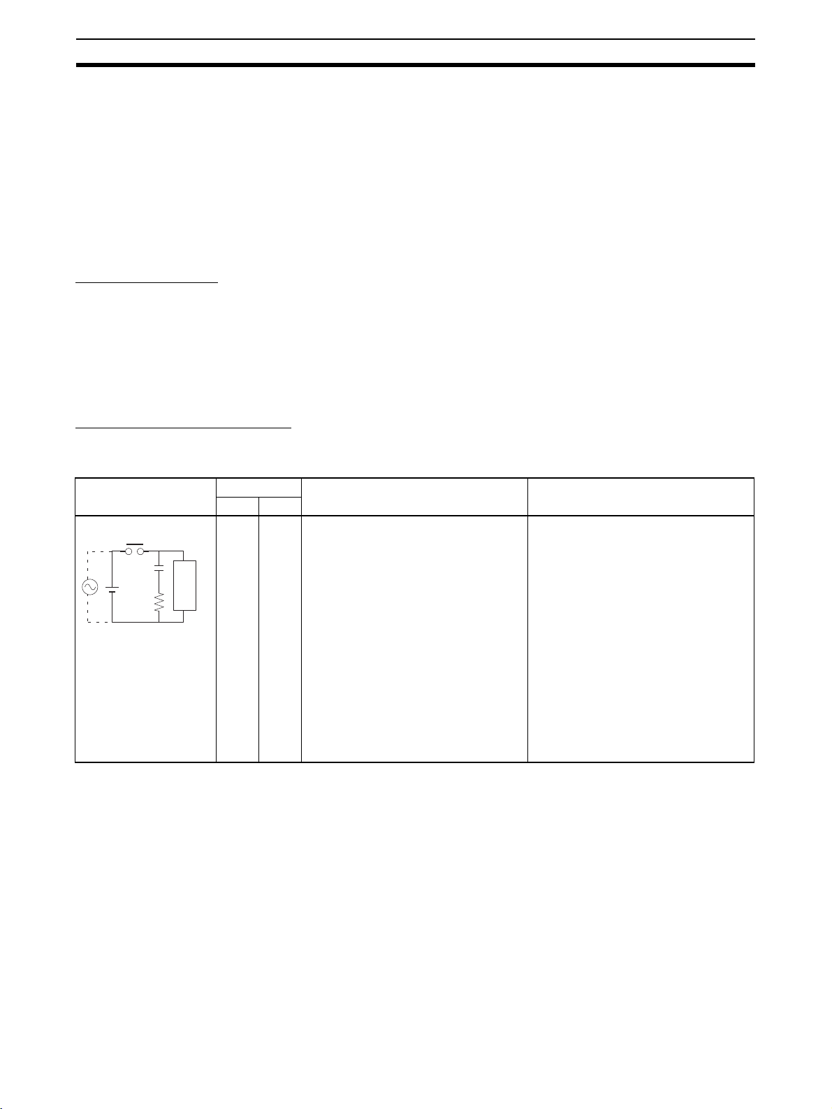
Countermeasure Examples
When switching an inductive load, connect an surge protector, diodes, etc., in
parallel with the load or contact as shown below.
Circuit Current Characteristic Required element
CR method
Power
supply
AC DC
Yes Yes If the load is a relay or solenoid, there
C
R
Inductive
load
is a time lag between the moment the
circuit is opened and the moment the
load is reset.
If the supply voltage is 24 or 48 V,
insert the surge protector in parallel
with the load. If the supply voltage is
100 to 200 V, insert the surge protector
between the contacts.
The capacitance of the capacitor must
be 1 to 0.5 µF per contact current of
1 A and resistance of the resistor must
be 0.5 to 1 Ω per contact voltage of 1 V.
These values, however, vary with the
load and the characteristics of the
relay. Decide these values from experiments, and take into consideration that
the capacitance suppresses spark discharge when the contacts are separated and the resistance limits the
current that flows into the load when
the circuit is closed again.
The dielectric strength of the capacitor
must be 200 to 300 V. If the circuit is an
AC circuit, use a capacitor with no
polarity.
xx
Page 20
Conformance to EC Directives 4
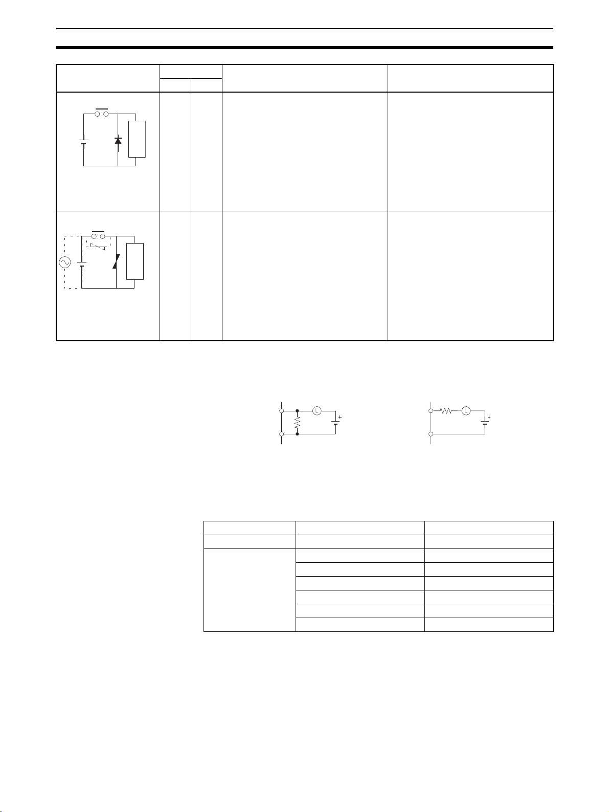
Circuit Current Characteristic Required element
AC DC
Diode method
Power
supply
Varistor method
Power
supply
No Yes The diode connected in parallel with
the load changes energy accumulated
by the coil into a current, which then
flows into the coil so that the current
will be converted into Joule heat by the
Inductive
load
resistance of the inductive load.
This time lag, between the moment the
circuit is opened and the moment the
load is reset, caused by this method is
longer than that caused by the CR
method.
Yes Yes The varistor method prevents the impo-
sition of high voltage between the contacts by using the constant voltage
characteristic of the varistor. There is
time lag between the moment the cir-
Inductive
load
cuit is opened and the moment the load
is reset.
If the supply voltage is 24 or 48 V,
insert the varistor in parallel with the
load. If the supply voltage is 100 to
200 V, insert the varistor between the
contacts.
The reversed dielectric strength value
of the diode must be at least 10 times
as large as the circuit voltage value.
The forward current of the diode must
be the same as or larger than the load
current.
The reversed dielectric strength value
of the diode may be two to three times
larger than the supply voltage if the
surge protector is applied to electronic
circuits with low circuit voltages.
---
When switching a load with a high inrush current such as an incandescent
lamp, suppress the inrush current as shown below.
Countermeasure 2Countermeasure 1
OUT
R
COM
Providing a dark current of approx.
one-third of the rated value
through an incandescent lamp
OUT
COM
Providing a limiting resistor
R
The following Unit and Cables can be used with the FQM1-series Flexible
Motion Controller.
Name Model Cable length
Relay Unit XW2B-80J7-1A --Controller Connect-
ing Cables
XW2Z-050J-A28 0.5 m
XW2Z-100J-A28 1 m
XW2Z-050J-A30 0.5 m
XW2Z-100J-A30 1 m
XW2Z-050J-A31 0.5 m
XW2Z-100J-A31 1 m
xxi
Page 21
Data Backup 5
5Data Backup
The user programs, I/O memories, and other data in the Coordinator Module
and Motion Control Modules is backed up either by a super capacitor or flash
memory, as listed in the following table.
Module Data Data backup
Coordinator Module Error log RAM with super
Motion Control Module DM Area words D30000 to D32767
Error log
Coordinator Module User program
System Setup
DM Area words D30000 to D32767
Motion Control Module User program
System Setup
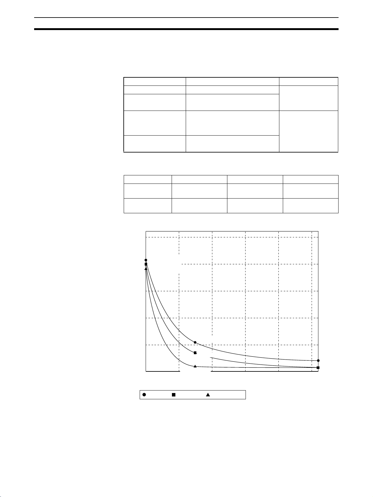
The data backup time of the super capacitor is given in the following table and
shown in the following graph.
Temperature Initial After 5 years After 10 years
Ta = 2 5°C 101.61 hours
(4.23 days)
Ta = 4 0°C 26.39 hours
(1.09 days)
96.2 hours
(4.01days)
15.28 hours 4.16 hours
capacitor
Flash memory
90.8 hours
(3.78 days)
Super Capacitor Backup Times
120
25°C: 101.61 h
25°C: 96.20 h
96
Backup time (h)
25°C: 90.80 h
72
48
40°C: 26.39 h
24
40°C: 15.28 h
0
25 35 45 55 65 75
Initial value,
40°C: 4.16 h
Ambient temperature (°C)
After 5 years, After 10 years
xxii
Note 1. The times give above assume that the capacitor is completely charged.
Power must be supply to the FQM1 for at least 20 minutes to completely
charge the capacitor.
2. The backup time of the super capacitor is reduced as the capacitor ages.
It is also affected by the ambient temperature. Use portion of the DM Area
backed up by the super capacitor only for data that is to be held during mo-
Page 22
Data Backup 5
mentary power interruptions. For operating parameters and other longterm data, use the portion of DM Area stored in flash memory in the Coordinator Module and transfer it to the Motion Control Modules before starting operation.
The data in the DM Area and error log will become unstable or corrupted if the
power to the system is OFF for longer than the backup time.
If the power supply is to be turned OFF for an extended period of time, use
D30000 to D32767 in the Coordinator Module, which is backed up in flash
memory, to store data.
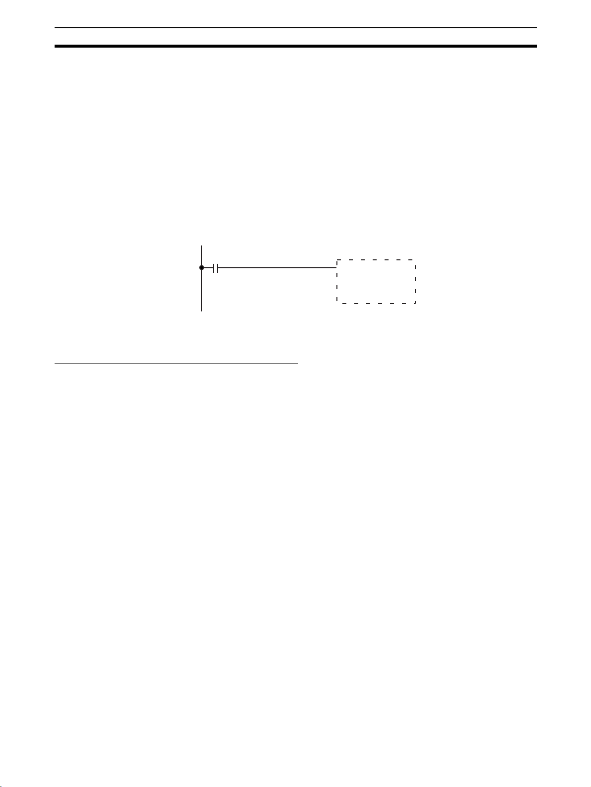
Otherwise, the Memory Not Held Flag (A404.14) can be used as the input
condition for programming using data in areas stored for power interruptions
to perform suitable processing.
A404.14: Turns ON when power is turned ON if data stored for power interruptions in the DM Area or error log is corrupted.
A404.14
Processing for
corruption of data
backed up for
power interruptions
DM Area words D30000 to D32767 in the Coordinator Module are backed up
in flash memory as described in the next section.
Backing Up DM Area Data in Flash Memory
DM Area words D30000 to D32767 in the Coordinator Module is read from
flash memory when the power supply is turned ON. We recommend using DM
Area words D30000 to D32767 in the Coordinator Module to store operating
parameters and other data required for system operation and then using the
DM transfer function to transfer the data from the Coordinator Module to the
Motion Control Modules at the start of operation.
xxiii
Page 23

Data Backup 5
xxiv
Page 24

Features and System Configuration
This section describes the features of the FQM1 and its system configuration.
1-1 Outline of FQM1 Flexible Motion Controller . . . . . . . . . . . . . . . . . . . . . . . . 2
1-2 FQM1 Configuration. . . . . . . . . . . . . . . . . . . . . . . . . . . . . . . . . . . . . . . . . . . . 4
1-3 Modules. . . . . . . . . . . . . . . . . . . . . . . . . . . . . . . . . . . . . . . . . . . . . . . . . . . . . . 6
1-4 CX-Programmer . . . . . . . . . . . . . . . . . . . . . . . . . . . . . . . . . . . . . . . . . . . . . . . 8
1-5 Expanded System Configuration. . . . . . . . . . . . . . . . . . . . . . . . . . . . . . . . . . . 9
1-5-1 Serial Communications. . . . . . . . . . . . . . . . . . . . . . . . . . . . . . . . . . . 9
1-5-2 Systems. . . . . . . . . . . . . . . . . . . . . . . . . . . . . . . . . . . . . . . . . . . . . . . 9
1-6 Basic Operating Procedure . . . . . . . . . . . . . . . . . . . . . . . . . . . . . . . . . . . . . . . 13
1-6-1 Examples. . . . . . . . . . . . . . . . . . . . . . . . . . . . . . . . . . . . . . . . . . . . . . 15
1-7 Function Tables Arranged by Purpose . . . . . . . . . . . . . . . . . . . . . . . . . . . . . . 19
1-7-1 Sync Cycles and Synchronized data. . . . . . . . . . . . . . . . . . . . . . . . . 19
1-7-2 Position and Speed Control . . . . . . . . . . . . . . . . . . . . . . . . . . . . . . . 21
1-7-3 Measuring Input Pulses. . . . . . . . . . . . . . . . . . . . . . . . . . . . . . . . . . . 25
1-7-4 High-speed Analog I/O Control . . . . . . . . . . . . . . . . . . . . . . . . . . . . 26
1-7-5 Controlling Timing . . . . . . . . . . . . . . . . . . . . . . . . . . . . . . . . . . . . . . 28
SECTION 1
1
Page 25
Outline of FQM1 Flexible Motion Controller Section 1-1
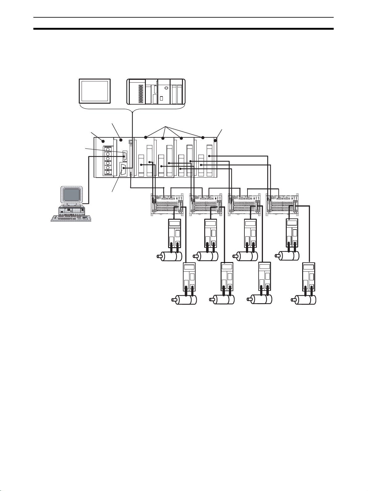
1-1 Outline of FQM1 Flexible Motion Controller
The FQM1 (Flexible Quick Motion) is a stand-alone Flexible Motion Controller
that can be used to create flexible high-speed, high-precision motion control
systems for 2 to 8 axes.
PT (Monitor
parameter
settings)
Power Supply Unit
Peripheral port
CX-Programmer
or
Coordinator Module
RS-232C port
Servo Relay Units
Motion Control Modules
RS-422A
Host Controller
End Module
Servomotors and
Servo Drivers
Flexible Configurations of
Up To 8 Axes
An FQM1 Flexible Motion Controller System is made up of a Power Supply
Unit, a Coordinator Module, one or more Motion Control Modules, and an End
Module.
Motion Control Modules are available with either pulse I/O or analog I/O, and
a mixture of up to four Motion Control Modules can be included in one system
(up to three if only analog I/O Motion Control Modules are used.) A flexible
system ideal for the application can be created because each Motion Control
Module controls two axes, giving total motion control of eight axes when four
Motion Control Modules are connected.
High-speed Processing Each Motion Control Module and Coordinator Module has independent ladder
programming, allowing high-speed independent control of pulse and analog
I/O. Data can be shared between all Modules. The Coordinator Module performs general-purpose I/O control and manages overall system operation.
2
Page 26
Outline of FQM1 Flexible Motion Controller Section 1-1
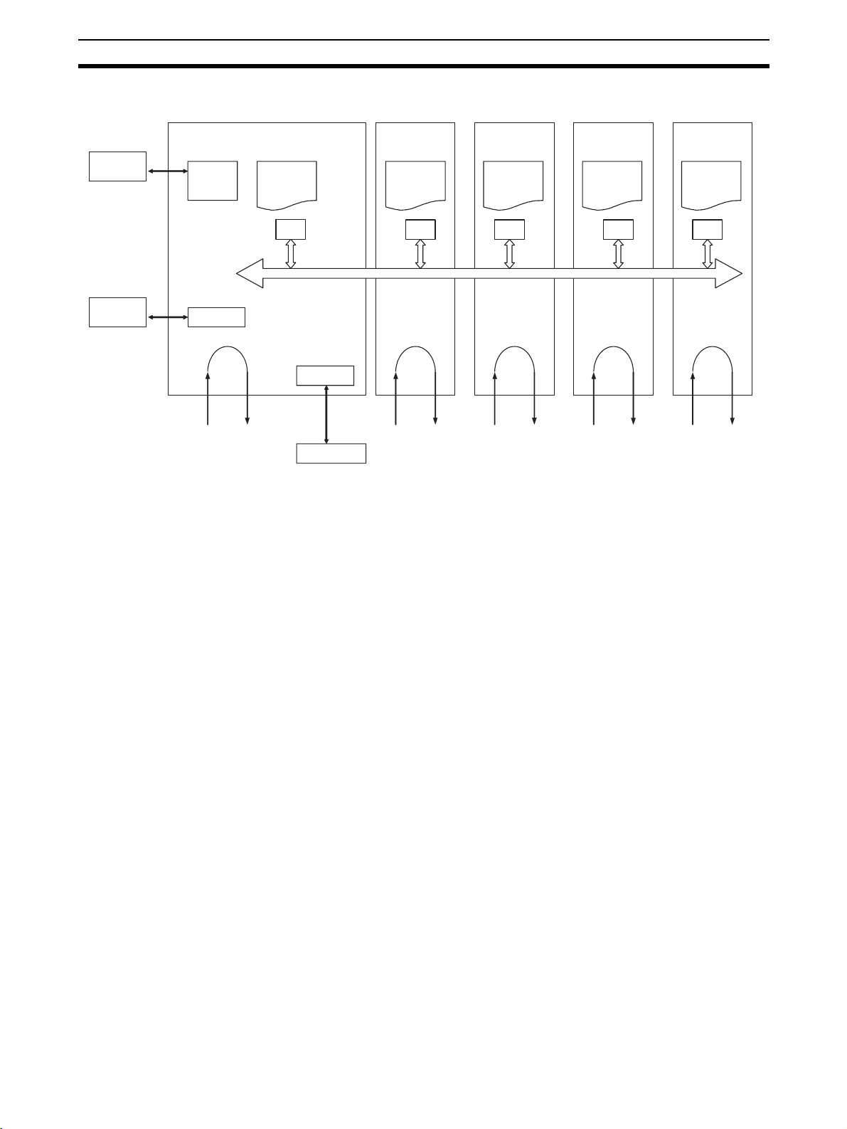
Coordinator Module
CXProgrammer
PT, host
computer,
etc.
Peripheral port
RS-232C
Normal I/O
Built-in RS-232C Port in
Coordinator Module
Ladder
program
RS-422A
Servo Driver
Motion Control
Module #1
Ladder
program
Special I/O
(pulse or
analog I/O)
Basic I/O
Motion Control
Module #2
Ladder
program
Special I/O
(pulse or
analog I/O)
Basic I/O
Motion Control
Module #3
Ladder
program
Special I/O
(pulse or
analog I/O)
Basic I/O
Motion Control
Module #4
Ladder
program
Special I/O
(pulse or
analog I/O)
Basic I/O
A Programmable Terminal (PT) can be connected to the Coordinator Module
to monitor present values on the PT or make parameter settings for Servomotors from the PT.
The RS-232C port is useful for a variety of applications. It can be used, for
example, to connect to a host computer or for a Serial PLC Link connection to
a SYSMAC CJ1M Programmable Controller.
Built-in RS-422A Port in
Coordinator Module
Motion Control with
Familiar Ladder
Programming
Built-in General-purpose
I/O in Coordinator Module
Built-in General-purpose
I/O in Motion Control
Modules
Connections for Absolute
Servomotors
High-speed Counter Latch
Function
Pulse Input Sampling
Function
A PT can be connected to the Coordinator Module so that Servo parameters
can be read from and written to Servomotors/Servo Drivers using a Serial
Gateway Function.
Commands can also be sent from the Coordinator Module ladder program to
Servomotors/Servo Drivers.
The Coordinator Module and Motion Control Modules each have their own
ladder program, which perform basic I/O and special I/O (pulse I/O and analog I/O).
The Coordinator Module has 24 built-in I/O (16 inputs and 8 outputs) for communications with host controllers and 12 inputs and 8 outputs for Motion Control Modules.
Motion Control Modules have 12 contact inputs and 8 contact outputs for I/O
with peripheral devices.
Motion Control Modules can read absolute position data from W-series Absolute Servomotors/Servo Drivers.
The high-speed counter latch function latches the high-speed counter's PV
using 2 external signals. Ladder programs can then be used to read the
latched values.
The number of pulse inputs within a specified time can be measured.
3
Page 27
FQM1 Configuration Section 1-2
Pulse Input Frequency
Measurement Function
Wide Variety of Interrupt
Functions
The speed of pulse inputs can be measured at the same time as the number
of pulse inputs is counted.
The FQM1 can provide high-speed I/O responses because it has a wide variety of functions for starting interrupt tasks, in addition to input interrupts, interval timer interrupts, high-speed counter interrupts, and pulse output interrupts.
High-speed Analog I/O
Supported
Motion Control Modules with analog I/O support linear (displacement/length
measurement) sensor input, inverter control, and control of Servomotors with
analog-input Servo Drivers. This gives flexibility for a great variety of motion
applications.
Writing and Monitoring
Ladder Programs
The ladder program for each Module is written using CX-Programmer Ver.
5.01 or later (see note) and then written to each Module via the peripheral
port on the Coordinator Module.The ladder program is saved in each Module
and operation of the program can be monitored from the CX-Programmer.
Note FQM1 Patch Software must be installed for CX-Programmer Ver. 5.0.
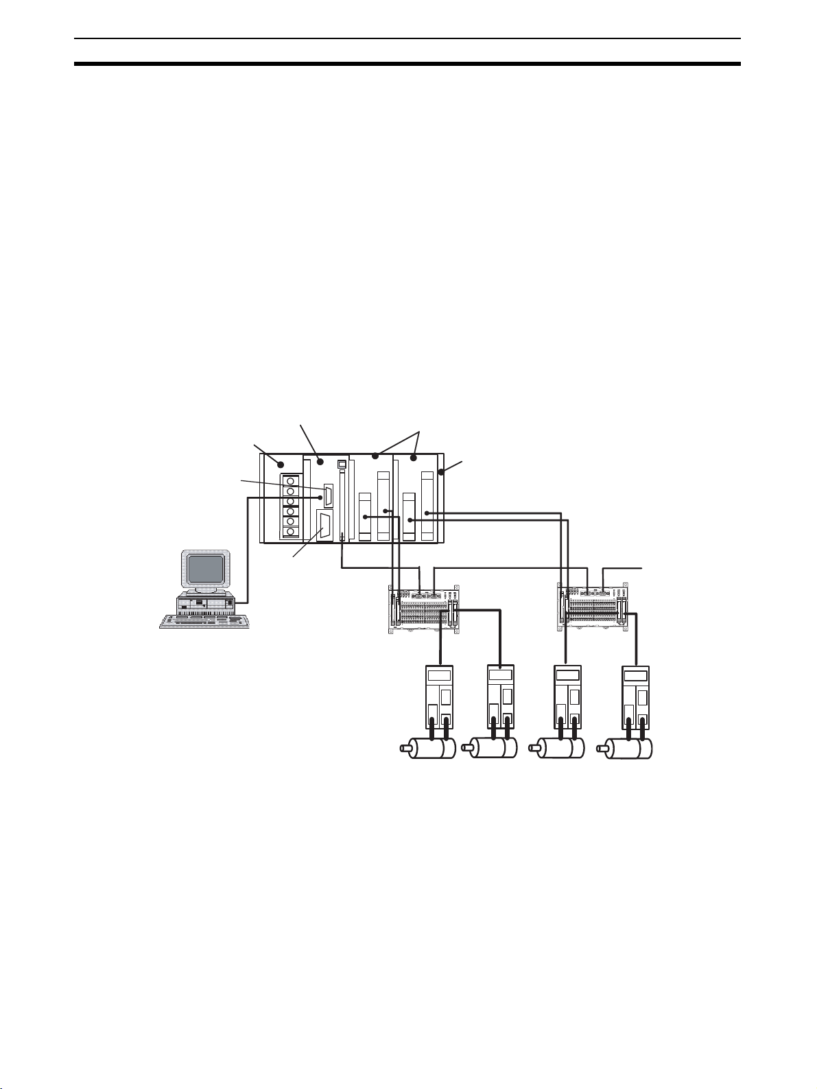
1-2 FQM1 Configuration
Coordinator Module
Power Supply Unit
Peripheral port
Motion Control Modules
End Module
CX-Programmer
Note The number of Motion Control Modules with Analog I/O that can be connected
RS-232C port
Servo Relay Units
Servomotors/
Servo Drivers
RS-422A
The FQM1 consists of a Power Supply Unit, a Coordinator Module, one or
more Motion Control Modules, and an End Module. Motion Control Modules
are available with either pulse I/O or analog I/O and up to four Motion Control
Modules can be connected in one system. (See note.)
is limited by the output capacity of the Power Supply Unit.
4
Page 28

FQM1 Configuration Section 1-2
FQM1-CM001 Coordinator
Module
FQM1-MMP21/MMA21
Motion Control Modules
One Coordinator Module is required in an FQM1. The Coordinator Module
provides the following:
I/O: 16 inputs, 8 outputs
Program capacity: 5 Ksteps
DM Area capacity: 32 Kwords (DM)
• The CX-Programmer (Ver. 5.01 or later) is connected to the peripheral
port on the Coordinator Module, and a PT (Programmable Terminal) or
other device is connected to the RS-232C port.
• The Coordinator Module has its own ladder program, which is used to
coordinate Motion Control Module data.
• The Coordinator Module has 24 general-purpose I/O (16 inputs and 8 outputs).
• The Coordinator Module has a Cyclic Refresh Bit Area, in which 10 words
are allocated for cyclic refreshing with each Motion Control Module. This
area is refreshed each Coordinator Module cycle.
• The Coordinator Module has a Synchronous Data Link Bit Area, in which
4 words are allocated for sharing with the Synchronous Data Link Bit Area
of each Motion Control Module.
Each Motion Control Module provides the following:
Pulse I/O Motion
Control Module
Analog I/O Motion
Control Module
FQM1-MMP21 Program capacity: 5 Ksteps
Pulse inputs: 2
Pulse outputs: 2
General-purpose inputs: 12
General-purpose outputs:8
FQM1-MMA21 Program capacity: 5 Ksteps
Pulse inputs: 2
Analog inputs: 1
Analog outputs: 2
General-purpose inputs: 12
General-purpose outputs: 8
CJ1W-PA202/PA205R
Power Supply Units
• Rotary Encoders, Linear Sensors, Servos, Inverters, etc., can be connected to the special I/O.
• Each Motion Control Module has a ladder program for executing motion
control and other functions.
• Each Motion Control Module has 20 general-purpose I/O (12 inputs and 8
outputs).
• Each Motion Control Module has 10 words allocated in the Coordinator
Module's Cyclic Refresh Bit Area that is refreshed every Coordinator
Module cycle.
• Each Module cycle, 4 words of Motion Control Module Synchronous Data
Link Bit Area data is shared with the Coordinator Module's Synchronous
Data Link Bit Area.
SYSMAC CJ-series Power Supply Units are used.
CJ1W-PA202 100 to 240 V AC, output capacity: 5 V DC, 2.8 A, 24 V DC, 0.4 A,
up to 14 W total.
CJ1W-PA205R 100 to 240 V AC, output capacity: 5 V DC, 5.0 A, 24 V DC, 0.8 A,
up to 25 W total.
Select a Power Supply Unit with a capacity greater than the total current consumption of the connected Modules.
5
Page 29

Modules Section 1-3
FQM1-TER01 End Module One End Module is supplied with the Coordinator Module. Always attach the
End Module because it acts as a terminator for the system. A fatal error will
occur if no End Module is attached.
Other Peripheral Devices Special Servo Relay Units are available for connecting the FQM1 Flexible
Motion Control system to OMRON W-series and SMARTSTEP Servo Drivers.
Specific cables suitable for the connected Servomotor/Servo Driver models
and the FQM1 Motion Control Module models are also available.
1-3 Modules
The Coordinator Module acts as the interface between the FQM1 system and
peripheral devices, shares data with each Motion Control Module, and synchronizes specific data (e.g., virtual axis data) between Modules.
Item Details
Functions Interfaces for
peripheral
devices
Sharing data with
each Motion
Control Module
(each Coordinator Module cycle)
Synchronized
sharing of special
data between
Modules (broadcast at specified
sync cycle)
DM data transfer
with specific
Motion Control
Modules (as
required)
I/O Serial communi-
cations
General-purpose
I/O
Programs Program capacity 5 Ksteps (for data exchange with host computer, coordination of Motion Control Modules,
Connection with the CX-Programmer (peripheral port)
Connection with PT for monitoring and parameter settings (RS-232C port)
Connections with Servo Drivers (RS-422A port)
The 10 words are allocated for each Motion Control Module in the Cyclic Refresh Bit Area
of the Coordinator Module (CIO 0100 to CIO 0139), based on the Motion Control Module
slot number. These words correspond to CIO 0100 to CIO 0109 in the Cyclic Refresh Bit
Area of each Motion Control Module.
• Coordinator Module to Motion Control Module: 5 words (General-purpose output)
• Motion Control Module to Coordinator Module: 5 words (General-purpose input: 4 words,
program RUN, fatal errors, non-fatal errors)
This cyclic refresh data is refreshed every Coordinator Module cycle.
User-specified synchronous data (see following list) can be allocated to CIO 0200 to CIO
0219 in the Synchronous Data Link Bit Area of the Coordinator Module and each Motion
Control Module, 4 words at a time (2 types of data × 2 words). The allocations are fixed,
starting with the Coordinator Module and followed by Motion Control Modules in order of
slot number.
• Any ladder program data
• High-speed counter PV
• Pulse output PV
• Analog input PV
• Analog output PV
• Built-in I/O input values
The synchronous data is broadcast each specified sync cycle and all other Modules
receive this data in essentially real-time.
DM data (499 words max.) can be transferred in the specified direction between the specified words in the DM Area in the specified Motion Control Module and the specified DM
Area words in the Coordinator Module when the DM Write Request Bit (A530.00) or DM
Read Request Bit (A530.01) in the Auxiliary Area of the Coordinator Module turns ON.
• Peripheral port: Peripheral bus (for CX-Programmer)
• One RS-232C port: NT Link (for OMRON PTs), Host Link (for host computers), or no protocol (for PLCs)
• One RS-422A port (Same connector as general-purpose I/O): 1:N communications with
Servo Drivers (for transferring parameters to Servo Drivers)
General-purpose inputs: 16
General-purpose outputs: 8
and other peripheral programming)
40-pin connector (including RS-422A)
6
Page 30
Modules Section 1-3
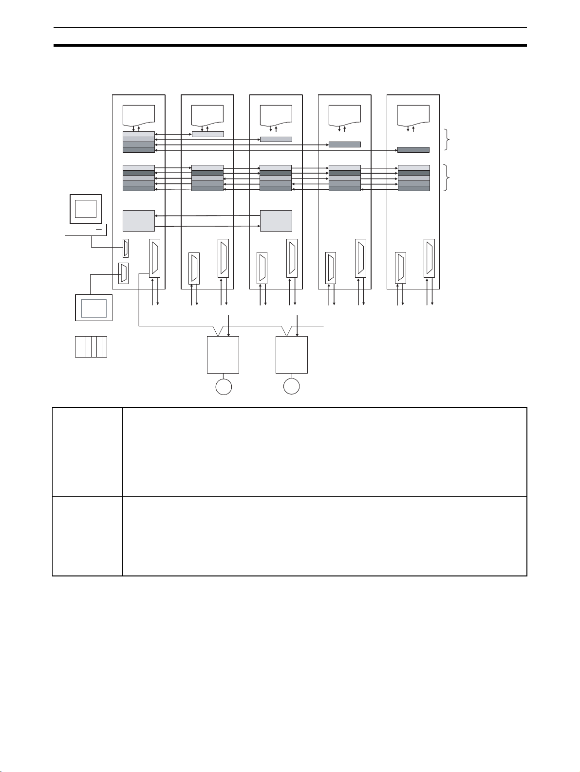
Outline of Internal Data Exchange and I/O
Coordinator
Module
Ladder program Ladder program Ladder program Ladder program Ladder program
CX-Programmer
Motion Control
Module #1
Motion Control
Module #2
Motion Control
Module #3
Motion Control
Module #4
Cyclic Refresh Bit
Area (refreshed each
Coordinator Module
cycle)
Sync Data Link Bit
Area (Broadcast
each Motion
Control Module
cycle)
Peripheral port
RS-232C
PT
PLC
Coordinator
Module
Motion Control
Modules
DM DM
DM data transfer
(as required)
16 inputs
8 outputs
RS-422A
(for parameter settings)
12 inputs
8 outputs
Special I/O 12 inputs
W-series/
SMART
STEP
Servo
Driver
8 outputs
Special I/O 12 inputs
W-series/
SMART
STEP
Servo
Driver
8 outputs
Special I/O 12 inputs
8 outputs
Special I/O
• Peripheral port for connecting CX-Programmer and RS-232C port for connecting PTs and other
devices
• Ladder program for coordinating Motion Control Module data and other functions
• 24 general-purpose I/O
• 10 words of cyclic refresh data for each Motion Control Module allocated in Cyclic Refresh Bit Area,
which is refreshed each Coordinator Module cycle
• 4 synchronous data link words allocated for each Motion Control Module in Coordinator Module's Synchronous Data Link Bit Area, which is shared each Module cycle
• Linear Sensors, Servo Drivers, Inverters, etc., connected to special I/O
• Ladder program for executing motion control and other functions
• 20 general-purpose I/O
• 10 words of cyclic refresh data for each Motion Control Module allocated in its Cyclic Refresh Bit Area,
which is refreshed each Coordinator Module cycle
• 4 synchronous data link words allocated for each Motion Control Module in Coordinator Module's Synchronous Data Link Bit Area, which is shared each Module cycle
7
Page 31

CX-Programmer Section 1-4
1-4 CX-Programmer
The CX-Programmer provides software functions for programming and
debugging.
FQM1 Patch Software must be installed for the CX-Programmer Ver. 5.0
(Model: WS02-CXPC1-E-V50) to use it to create ladder programs, make settings in the System Setup, and monitor operation. The FQM1 Patch Software
can be installed for CX-Programmer Ver. 5.0 or later, but not to Ver. 4.0 or earlier versions. Refer to 8-1 CX-Programmer.
CX-Programmer
Item Details
Applicable Motion
Controllers
OS Microsoft Windows
Personal computers IBM PC/AT or com-
Connection method Peripheral port or built-in RS-232C port on the Coordinator
Communications
protocol with FQM1
Offline functions Programming, editing of I/O memory, System Setup, printing
Online functions Transferring comparing data, monitoring, System Setup
Main functions 1. Programming functions: Creating and editing of applicable
FQM1 Series
Note CX-Programmer can also be used for SYSMAC CS/CJ-
series PLCs.
95, 98, or NT4.0
Service Pack 6
patible
Module
Peripheral Bus or Host Link
FQM1 ladder or mnemonic programs.
2. Changing operating modes for each Module.
3. Transfer functions: Transferring programs, I/O memory data,
and System Setup between computer and Modules.
4. Monitoring program execution status: Monitoring I/O bit status and PV using ladder display, monitoring I/O bit status
and PV using mnemonic display, and monitoring PV using
I/O memory display.
Microsoft Windows
2000 or Me
IBM PC/AT or compatible
Microsoft Windows
XP
IBM PC/AT or compatible
Note The CX-Programmer can be connected online to FQM1 Coordinator Modules
and Motion Control Modules at the same time. If the default baud rate is
changed when Coordinator and Motion Control Modules are connected at the
same time, set the baud rate to 38.4 kpps max.
8
Page 32

Expanded System Configuration Section 1-5
1-5 Expanded System Configuration
1-5-1 Serial Communications
The FQM1 system can be expanded using the two serial ports built into the
Coordinator Module: Peripheral port and RS-232C port.
System Configuration
Host computer
CX-Programmer
Peripheral
port
Host Link
RS-232C port
Automatic detection of
communications parameters
Coordinator Module
1-5-2 Systems
The serial communications port mode (protocol) can be switched in the Coordinator Module’s System Setup. Depending on the protocol selected, the following systems can be configured.
Protocols The following protocols support serial communications.
Protocol Main connection Use Applicable commands and
communications
instructions
Host Link (SYSMAC WAY)
No-protocol (custom) communications
NT Links (1: N) OMRON Programmable Termi-
Peripheral Bus
(Toolbus)
Serial PLC Link
Slave
Serial Gateway OMRON Programmable Termi-
Personal computer
OMRON Programmable Termi-
nals (PTs)
General-purpose external devices
Servo Drivers
Host controllers
nals (PTs)
CX-Programmer Communications between the
OMRON PLC Communications between
nals (PTs)
Servo Drivers
Communications between the
host computer and the Module
No-protocol communications with
general-purpose devices, host
controllers, and Servo Drivers
High-speed communications with
Programmable Terminals via
direct access
CX-Programmer running on a
computer and the FQM1
OMRON PLC and the FQM1
Communications between a PT
and W-series or SMARTSTEP
Servo Drivers via the FQM1
Host Link commands/ FINS
commands
TXD(236) instruction and
RXD(235) instruction
None
None
None
FINS commands
9
Page 33

Expanded System Configuration Section 1-5
Host Link System The Host Link System allows the I/O memory of the Modules to be read/writ-
ten and the operating mode to be changed from a host computer (personal
computer or Programmable Terminal (PT)) by executing Host Link commands
or FINS commands that are preceded by a Host Link header and followed by
a terminator. A Host Link System is possible for either the peripheral port or
the RS-232C port on the Coordinator Module.
Host computer
Applicable Ports
Coordinator Module
RS-232C
Host link commands
or FINS commands
embedded in Host Link
commands
Note: Turn ON pin 2 on the DIP switch on the front of the
Coordinator Module and set the serial communications
mode in the System Setup to "Host Link."
Peripheral port
Yes
(See note.)
RS-232C port
Yes
No-protocol (Custom)
Communications
System via RS-232C
Port
NT Link System
(1:N Mode, Standard)
No-protocol communications allow simple data transmissions, such as inputting bar code data and outputting printer data using communications port I/O
instructions TXD(236) and RXD(235). The start and end codes can be set
and, RS and CS signal control is also possible with no-protocol communications.
Coordinator Module
Applicable Ports
Coordinator Module
Peripheral
No
Note Set the serial communications
RXD(235) instruction
RS-232C
TXD(236) instruction
RS-232C
mode in the System Setup to
"non-procedural."
Yes
RS-422A
Yes
If the FQM1 and a Programmable Terminal (PT) are connected together using
the RS-232C port, the allocations for the PT’s status control area, status notify
area, objects such as touch switches, indicators, and memory maps can be
allocated in the I/O memory of the FQM1.
The NT Link System allows the PT to be controlled by the FQM1, and the PT
can periodically read data from the status control area of the FQM1, and perform necessary operations if there are any changes in the area. The PT can
communicate with the FQM1 by writing data to the status notify area of the
FQM1 from the PT. The NT Link System allows the PT status to be controlled
and monitored without using FQM1 ladder programming. The ratio of FQM1
Controllers to PTs is 1: n (n
≥ 1).
10
Page 34

Expanded System Configuration Section 1-5
Set the PT communications settings for a 1:N or Standard NT Link. An NT
Link System is possible for either the peripheral port or the RS-232C port.
NT Link
1:N Mode
RS-232C
PT
NT Link
1:N Mode
Applicable Ports
Coordinator Module
RS-232C port
Yes
RS-232C
RS-232C to RS-422A/485
Conversion Adapter
RS-422A/485
PT
PT
Peripheral port
Yes
(See note.)
Note Turn ON pin 2 on the DIP
switch on the front of the
Coordinator Module and set
the serial communications
mode in the System Setup to
an NT Link.
PT
Note (1) The FQM1 can be connected to any PT port that supports 1:N NT Links.
It cannot be connected to the RS-232C ports on the NT30 or NT30C, because these ports support only 1:1 NT Links.
(2) The Programming Console functionality of a PT (Expansion Function)
cannot be used.
(3) When more than one PT is connected to the same FQM1, be sure that
each PT is assigned a unique unit number. Malfunctions will occur if the
same unit number is set on more than one PT.
(4) The NT Link System includes 1:1 and 1:N modes. These two modes are
not compatible as serial communications modes.
Serial PLC Link Slave The FQM1 can be connected to a Serial PLC Link by linking to a Serial PLC
Master. (It cannot be connected by the Complete Link Method.) Program-free
data exchange can be achieved between the master and slave by connecting
a CJ1M CPU Unit as the master and the FQM1 as the slave. The FQM1 connection is made to the RS-232C port on the Coordinator Module.
CIO 0080 to CIO 0099 in the Serial PLC Link Bit Area in the Coordinator Module are shared with the CJ1M master as shown below
Note Use a CJ1W-CIF11 RS-232C to RS-422A/485 Conversion Adapter when con-
necting more than one FQM1 to the same CJ1M CPU Unit (1:N, where N = 8
max.).
11
Page 35

Expanded System Configuration Section 1-5
1:N Connection between CJ1M and FQM1 Controllers
CJ1M CPU Unit (master)
CJ1W-CIF11 RS-232C to RS-422A/485
Conversion Adapter connected to RS-232C port
RS-422A/485
Data sharing
FQM1
(slave)
Coordinator Module
FQM1
(slave)
CJ1W-CIF11 RS-232C to RS-422A/485
Conversion Adapters connected to RS-232C ports
8 nodes max.
1:1 Connection between CJ1M and FQM1 Controller
RS-232C
Data sharing
FQM1
(slave)
Coordinator Module
FQM1
(slave)
CJ1M CPU Unit (master)
Serial Gateway Reading/writing Servo Parameters and other data in Servo Drivers connected
via RS-422A can be performed through the FQM1 Coordinator Module from
an NS-series PT or computer application running on CX-Server. The serial
communications mode for the RS-422A port on the FQM1 Coordinator Module is set to Serial Gateway to achieve this.
Servo Drivers
OMRON’s W-series or SMARTSTEP Servo Drivers can be connected.
Connectable to RS-422A
System Configuration
Example
Smart Active Parts on an NS-series PT connected via an NT Link can be used
to access W-series or SMARTSTEP Servo Drivers.
12
Page 36

Basic Operating Procedure Section 1-6
(
NS-series PT
Smart Active Parts
No-protocol (Custom)
Communications
System via RS-422A
Port
NT
Link
conversion
Coordinator Module
FQM1
Servo parameters Protocol
RS-422A
W-series
or SMART
STEP
Servo Driver
W-series
or SMART
STEP
Servo Driver
No-protocol communications allow simple data transmissions, such as inputting bar code data and outputting printer data using communications port I/O
instructions TXD(236) and RXD(235). The start and end codes can be set
with no-protocol communications.
Coordinator Module
Applicable Ports
Coordinator Module
Peripheral
No
Note Set the serial communications
RS-232C
mode in the System Setup to
"non-procedural."
Yes
RS-422A
Yes
RXD(235) instruction
TXD
236) instruction
1-6 Basic Operating Procedure
The following procedure outlines the normal steps to operate the FQM1.
1,2,3... 1. Installation
Connect the Power Supply Unit, Coordinator Module, Motion Control Modules, and End Module. Refer to 3-1-4 Connecting FQM1 Components for
details.
Mount the FQM1. Refer to 3-1-5 DIN Track Installation for details
2. Wiring
Connect the power supply wiring and ground. Refer to 3-2-1 Wiring Power
Supply Units for details.
RS-422A
13
Page 37

Basic Operating Procedure Section 1-6
Wiring I/O terminals and connectors. Refer to 3-3 Wiring Module Connectors for details.
3. Initial Hardware Settings
Set the DIP switch on the front of the Coordinator Module as required. Re-
fer to 2-3 Coordinator Module for details.
4. Turning ON Power and Checking Initial Operation
Connect the CX-Programmer (using CX-Programmer Ver. 5.0 with the
FQM1 Patch Software installed). Refer to 3-1-4 Connecting FQM1 Com-
ponents for details.
Check the power supply wiring and voltage and then turn ON the power
supply. Check the RDY indicator and CX-Prorammer display. Refer to 8-2
Connecting the CX-Programmer for details.
5. System Setup Settings Using the CX-Programmer
With the FQM1 in PROGRAM mode, change the settings in the System
Setup as necessary from the CX-Programmer online. (Another method is
to change the System Setup in CX-Programmer offline and transfer it to the
Coordinator Module and Motion Control Modules.) Set the Sync Mode under Synchronization between Modules to ASync Mode to make debugging
easier. Refer to System Setup in the Coordinator Module on page 311 in
Appendix C System Setup, Auxiliary Area Allocations, and Built-in I/O Allocations for details.
6. Writing the Programs
Write the programs for the Coordinator Module and Motion Control Mod-
ules with the CX-Programmer. Refer to Appendix A Programming and to
the FQM1 Instructions Reference Manual (Cat. No. O011) for details.
7. Transferring the Programs
Transfer the programs from CX-Programmer to the Coordinator Module
and Motion Control Modules.
8. Testing Operation
a. Checking I/O Wiring
Output wiring With the FQM1 in PROGRAM mode, force-set output bits
and check the status of the corresponding outputs.
Input wiring Activate sensors and switches and either check the status
of the input indicators or check the status of the corresponding input bits with the CX-Programmer’s Bit/Word
Monitor operation.
14
b. Trial Operation
Test operation after switching the FQM1 to MONITOR mode.
c. Monitoring and Debugging
Monitor operation from the CX-Programmer. Use functions such as
force-setting/force-resetting bits, tracing, and online editing to debug
the program.
Note If the Coordinator and Motion Control Modules are connected at
the same time, set the baud rate to 38.4 kpps max.
9. Saving and Printing the Programs
Save the debugged ladder programs and System Setup.
10. Running the Programs
Switch the FQM1 to RUN mode to run the programs.
Page 38

Basic Operating Procedure Section 1-6
1-6-1 Examples
1. Installation Connect the Power Supply Unit, Coordinator Module, Motion Control Mod-
ules, and End Module to assemble the FQM1.
L1
AC100
-240V
INPUT
L2/N
NC
NC
Make sure that the total power consumption of the Modules is less than the
maximum capacity of the Power Supply Unit.
Use DIN Track to mount the FQM1 to the control panel.
PA202
AC100
INPUT
-240V
COMM1
COMM2
PRPHL
CM001
RDY
RUN
ERR
ON
1
IN OUT
OFF
1 2
0
1
2
3
4
5
6
2
7
8
9
10
11
CN1
RS422
4039
BA
FLEXIBLE
POWER
L1
L2/N
NC
NC
MOTION
CONTROLLER
PERIPHERAL
PORT
MMP21
RDY
A1
RUN
B1
ERR
A2
B2
0
1
2
3
4
5
6
2
1
7
2526
CN2
CN1
12
4039
BABA
2. Wiring Connect the power supply, ground, and I/O wiring.
3. Initial Hardware
Settings
Note When devices other than the CX-Programmer are connected to the peripheral
Set the DIP switch on the Coordinator Module. In particular, be sure that the
settings for the peripheral port are correct.
Example: When connecting the CX-Programmer to the peripheral port, turn
OFF pin 2.
port and RS-232C port, turn ON pin 2.
CM001
FLEXIBLE
MOTION
CONTROLLER
RDY
RUN
ERR
PRPHL
COMM1
COMM2
ON
1 2
OFF
15
Page 39

Basic Operating Procedure Section 1-6
4. Turning ON Power and Checking Initial Operation
Note The System Setup and user programs are backed up in built-in flash memory.
When the data is being backed up, a message indicating the data is being
transferred will be displayed on the CX-Programmer. Never turn OFF the
power supply to the FQM1 while data is being backed up.
5. System Setup
Settings
6. Writing the
Programs
These settings determine the Modules’ software configuration. Refer to
Appendix C System Setup, Auxiliary Area Allocations, and Built-in I/O Allocations for details.
Note The FQM1 is set to the Sync Mode by default. This mode must be changed on
the Coordinator Module when programming Motion Control Modules, transferring programs, or debugging. Set the mode to ASync Mode in the System
Setup of the Coordinator Module to enable changing the operating modes of
the Motion Control Modules and creating programs directly from the CX-Programmer.
Write each program with the CX-Programmer, including one cyclic task and
the required number of interrupt tasks.
1,2,3... 1. Add Motion Control Modules to the tree by executing Insert - PC once for
each Motion Control Module connected to the Coordinator Module.
16
2. When going online to Motion Control Modules through the Coordinator
Module, the node set for the FINS destination address in the network settings on the Change PC Type Window determines the Motion Control Module that is connected. Normally the node number is automatically allocated
for the Motion Control Module when Insert - PC is executed.
Page 40

Basic Operating Procedure Section 1-6
.
7. Transferring the
Programs
When the programs has been created in the CX-Programmer, they must be
transferred to the Motion Control Modules through the Coordinator Module.
8. Testing Operation
8-a) I/O Wiring Checks Check Output Wiring
With the FQM1 in PROGRAM mode, force-set and force-reset output bits
from the CX-Programmer and verify that the corresponding outputs operate
properly.
Check Input Wiring
Activate input devices, such as sensors and switches, and verify that the corresponding input indicators light. Also, use the Bit/Word Monitor operation
from the CX-Programmer to verify the operation of the corresponding input
bits.
8-b) Trial Operation Use the CX-Programmer to switch each Module to MONITOR mode.
Using the CX-Programmer
Coordinator Module
Peripheral
port
CX-Programmer
FQM1
Trial Operation
Select PC - Mode - MONITOR
Actual operation
Select PC - Mode - RUN.
8-c) Monitoring and
Debugging
There are several ways to monitor and debug FQM1 operation, including the
force-set and force-reset operations, differentiation monitoring, time chart
monitoring, data tracing, and online editing.
Force-Set and Force-Reset
When necessary, the force-set and force-reset operations can be used to
force the status of bits and check program execution.
From the CX-Programmer, select the bit to be force-set or force-reset and
then select Force On or Off from the PLC menu.
Differentiation Monitor
The differentiation monitor operation can be used to monitor the up or down
differentiation of particular bits. Use the following procedure from the CX-Programmer.
17
Page 41

Basic Operating Procedure Section 1-6
1,2,3... 1. Select the bit for differential monitoring.
2. Select Differential Monitor from the PLC Menu. The Differential Monitor
Dialog Box will be displayed.
3. Select Rising or Falling.
4. Click the Start Button. The buzzer will sound when the specified change is
detected and the count will be incremented.
5. Click the Stop Button. Differential monitoring will stop.
Time Chart Monitoring
The CX-Programmer’s time chart monitor operation can be used to check and
debug program execution.
Data Tracing
The CX-Programmer’s data trace operation can be used to check and debug
program execution.
Online Editing
When a few lines of the program in a Module have to be modified, they can be
edited online with the FQM1 in MONITOR mode or PROGRAM mode from
the CX-Programmer. When more extensive modifications are needed, upload
the program from the Module to the CX-Programmer, make the necessary
changes, and transfer the edited program back to the Module.
9. Save and Print the
Programs
To save a program, select File and then Save (or Save As) from the CX-Programmer menus.
To print a program, select File and then Print from the CX-Programmer
menus.
10. Run the Programs Switch the FQM1 to RUN mode to run the programs.
18
Page 42

Function Tables Arranged by Purpose Section 1-7
1-7 Function Tables Arranged by Purpose
1-7-1 Sync Cycles and Synchronized data
Purpose Operation Function used Details
Synchronizing 3
or more axes
Simple control
of all axes operations from the
Coordinator
Module
Synchronizing
all Motion Control Modules to
Coordinator
Module cycle
Sync Mode,
Sync Cycle
Time
Synchronous
Data Link Bit
Area
Constant Cycle
Time (Coordinator Module)
Sync Cycle
Time (matches
cycle time)
Cycle Time
(Motion Control
Modules)
Prohibit System
Interruption of
the Sync Mode
5-1 Synchronous Operation between Modules
Set Sync Mode to Sync and Sync Cycle Time to
0 ms. Executes Motion Control Module ladder
programs at the same time as Coordinator Module ladder program, which makes it easy to control Motion Control Module program execution
from the Coordinator Module ladder program.
5-2 Data Exchange between Modules
If information to be shared between Modules
every cycle is placed in the Synchronous Data
Link Bit Area, it is automatically shared between
Modules every cycle.
Synchronous operation is also possible because
programs can handle the same data between
different Modules.
Example: Sending position data for VIRTUAL
AXIS (AXIS) instruction from a Module; sending
high-speed counter PVs from pulse inputs, etc.
5-1 Synchronous Operation between Modules
The cycle time of the Coordinator Module can be
made constant using the Constant Cycle Time
function.
This constant cycle time is set as the Sync Cycle
Time in the FQM1.
5-1 Synchronous Operation between Modules
The Coordinator Module's constant cycle time is
set as the FQM1 Sync Cycle Time (as above).
The I/O refresh interval for the Motion Control
Module within that Sync Cycle Time is made
constant, and the I/O cycle with external interfaces is also made constant.
5-4-4 Settings
Used to synchronize, as much as possible, the
start of processing between Modules.
When system interrupts are prohibited, the variation in the start of processing between Modules
is approx. 2 µs.
19
Page 43

Function Tables Arranged by Purpose Section 1-7
Purpose Operation Function used Details
Synchronizing 3
or more axes
Fast contro l
loops
Make control
cycle as short
as possible with
Modules synchronized
Control operation using pulse
and analog data
simultaneously
Synchronizing
Motion Control
Modules only
Synchronizing
Motion Control
Modules to
Coordinator
Module cycle or
synchronizing
between Motion
Control Modules only
Changing to
Async Mode
Sync Mode,
Sync Cycle
Time
Synchronous
Data Link Bit
Area
Cycle Time
(Motion Control
Modules)
Prohibit System
Interruption of
the Sync Mode
Synchronous
Data Selection
Sync Mode 5-1 Synchronous Operation between Modules
5-1 Synchronous Operation between Modules
Set Sync Mode to Sync and Sync Cycle Time to
between 0.1 and 10.0 ms.
If the Coordinator Module cycle varies or gets
too long after connecting the FQM1 to peripheral
devices, Motion Control Module operation can
be synchronized to have short control cycles for
Motion Control Modules only.
The Sync Cycle Time can be set to any value.
Same as “Synchronous Data Link Bit Area,”
above.
5-1 Synchronous Operation between Modules
The Coordinator Module's constant cycle time is
set as the FQM1 Sync Cycle Time (as above).
The I/O refresh interval for the Motion Control
Module in that Sync Cycle Time is made constant and the I/O cycle with external interfaces is
also made constant.
Same as “Prohibit System Interruption of the
Sync Mode” above.
5-4 Synchronous Data Refresh
Information for I/O from different Motion Control
Modules can be stored within Modules and a
control loop created.
Select the type of synchronous data.
• Ladder execution results
• High-speed counter PV
• Pulse output PV
• Analog input values
• Analog output values
• Built-in I/O inputs
Set the Sync Mode to Async.
Each Module will no longer be synchronized,
bus refreshing will stop, and the Motion Control
Module overhead time will be minimized.
The minimum overhead time for FQM1-MMP21
is 0.19 ms.
20
Page 44

Function Tables Arranged by Purpose Section 1-7
1-7-2 Position and Speed Control
Purpose Operation Main functions
PTP positioning
using pulse I/O
Using Servo
Driver compatible with an
incremental
encoder or stepping Servomotor/Servo Driver
Using Servo
Drivers compatible with an
Absolute
Encoder
Controlling positioning speed
Controlling trapezoidal positioning speed
control
Defining the origin
Controlling positioning speed
Controlling trapezoidal positioning speed
used
• Relative pulse
output functions
• Pulse output
instructions
(SPED(885)(8
85), ACC(888),
PULS(886),
and
PLS2(887))
• PLS2(887)
instruction
Speed Change
Cycle Selection
(2 ms/1 ms)
Pulse Output PV
Reset
• Absolute Pulse
Output
• Pulse output
instructions
(SPED(885)(8
85), ACC(888),
PULS(886),
and
PLS2(887))
PLS2(887)
instruction
Pulse Output
Direction/Absolute Position Priority Mode
Setting
Details
7-6-6 Pulse Output Function Details
Set operating mode to Relative Pulse Output.
The number of pulses is determined from the
current position. Instructions to control pulses
and speed can be used, depending on what is to
be controlled. Speed can be controlled between
20 Hz and 1 MHz.
• Basic I/O can be used for origin signal and
other I/O, and pulse inputs can be used for
encoder inputs, for Servomotors/Servo Drivers
• For stepping motors, combination with basic
I/O and pulse (CW) + direction control is possible.
7-6-12 PLS2(887) Pulse Output Direction Priority Mode
Trapezoidal positioning at any acceleration/deceleration ratio.
The system will automatically switch to triangle
control (trapezoidal control without constant
speed interval) when acceleration/deceleration
conditions with specified total output pulses do
not lead to trapezoidal control.
7-6-11 Acceleration/Deceleration Rates in
ACC(888) and PLS2(887) Instructions
The speed change cycle of ACC(888) and
PLS2(887) instructions can be selected.
This is useful for fine control of time taken to
reach target speed or to reduce positioning time.
7-5-8 Pulse Input Function Description
Turn ON the Pulse Output PV Reset Bit at the
origin.
A626.00 (pulse output 1)/A627.00 (pulse output
2) turn ON.
7-6-6 Pulse Output Function Details
Change operating mode to Absolute Pulse Output.
The number of pulses in the command is handled as an absolute position. Everything else is
the same as relative pulse output.
Same as for Servo Drivers compatible with an
incremental encoder, outlined above.
7-6-12 PLS2(887) Pulse Output Direction Priority Mode
Can switch between giving priority to CW/CCW
output direction specification for PLS2(887)
instructions or absolute position specification to
determine output direction.
21
Page 45

Function Tables Arranged by Purpose Section 1-7
Purpose Operation Main functions
PTP positioning
using pulse I/O
PTP positioning
using analog I/O
Using Servo
Drivers compatible with an
Absolute
Encoder
Using Servo
Driver compatible with an
incremental
encoder
Use Servo Drivers compatible
with Absolute
Encoder
Reading PV
from Servo
Driver
Presetting the
absolute position to the pulse
output counter.
Position control
in semi-closed
loop using virtual pulse output
function
Position control
in semi-closed
loop using virtual pulse output
function
Reading current
position from
Servo Driver
Presets absolute position in
AXIS instruction
used
• Absolute
counter operation (absolute
linear/circular)
• High-speed
counter absolute encoder
read
Pulse output
counter PV convert (INI(880)
instruction)
• Virtual axis
(AXIS instruction)
• High-speed
counter (FB
pulse)
• Analog output
instructions
with position
deviation using
virtual axis and
high-speed
counter
As above 7-8 Virtual Pulse Output Function
• Absolute
counter mode
(absolute linear/circular)
• High-speed
counter absolute encoder
read
• High-speed
counter PV
• MOVL instruction
7-7 Functions for Servo Drivers Compatible with
Absolute Encoders
Set counter operation to Absolute Linear (CW−),
Absolute Circular, or Absolute Linear (CW+).
Uses OMRON W-series Servo Drivers and
reads the absolute position from the Servo
Driver before operation starts.
Once the origin has been set, it is easier to find
the origin by reading the absolute position
before operation starts.
7-6-6 Pulse Output Function Details
Reflects in the pulse output instruction the absolute value read using the absolute encoder read
instruction outlined above.
7-8 Virtual Pulse Output Function
Uses virtual axis (AXIS instruction) in relative
mode.
The current position output for the AXIS instruction is used as the command pulse to create a
position loop with the high-speed counter PV
(the feedback pulse from the Servo Driver). A
control loop for the analog output instruction is
generated according to this deviation and used.
Uses virtual axis (AXIS instruction) in absolute
mode. Everything else is the same as above.
Same as PTP positioning with pulse I/O when
Servo Drivers compatible with Absolute Encoder
used.
7-8 Virtual Pulse Output Function
Presets the high-speed counter PV read using
the high-speed counter absolute encoder read
instruction outlined above, and presets and uses
this PV as the current position output in the
AXIS instruction.
The PV is preset before executing AXIS instruction.
Details
22
Page 46

Function Tables Arranged by Purpose Section 1-7
Purpose Operation Main functions
PTP positioning
using analog I/O
Path control Drawing path
Synchronous
control
Simple positioning using inverters
with linear interpolation
Drawing path
with circular
interpolation
Drawing elliptical and other
special locus
Slave axis control synchronized to real
axis.
used
Stepped or
sloped analog
output corresponding to the
high-speed
counter PV
Executing electronic cam control for 2 axes
synchronized to
virtual axis
As above As above
As above As above
Electronic cam:
Changing target
position and
speed every
cycle based on
input pulse
(position or
angle for one
rotation, etc.) to
execute positioning.
• Target value
match instruction
(CTBL(882)
instruction) for
high-speed
counter
• Analog output
instruction
(SPED(885)
instruction) or
analog output
slope variation
(ACC(888)
instruction) in
interrupt tasks
• Virtual axis
(AXIS instruction)
• Create path
tables using
ladder program
(APR instruction)
• Electronic cam
pulse output
(PULS(886)
instruction)
• High-speed
counter PV
•Cam curve
generation or
cam curve
table every
cycle based on
ladder programming
(APR instruction)
• Pulse output
with specified
target position
and frequency
(PULS(886)
instruction)
• Constant cycle
time
Details
7-10 Analog Outputs
Used when positioning only using speed command according to analog output.
Applicable when speed patterns have been
determined based on specified positions.
An instruction to change the output variable
every time instructions are executed
(SPED(885) instruction) and an instruction to
change analog outputs at a specified rate of
change every 2 ms (ACC(888) instruction) are
available for analog outputs.
Fine speed control loops can be included using
the FQM1 high-speed cycle time and analog
output conversion functions (approx. 40 µs).
7-8 Virtual Pulse Output Function
Pulse output operation mode set to electronic
cam control mode (linear).
Virtual axis used as basic axis. Path can be
drawn by synchronizing 2 pulse output axes
(controlled as slave axes) with the basic axis.
Set the desired path pattern to the broken-line
approximation instruction (APR instruction) table
data, and execute pulse output control based on
the APR instruction calculation result for the
basic axis.
The maximum number of line points for one APR
instruction is 256, but multiple APR instructions
can be used in ladder programs so the number
of curve points can be increased by setting the
table data across multiple APR instructions.
7-6-14 Pulse Output Function Examples
Set pulse output operation mode to electronic
cam control mode (linear) or electronic cam control mode (circular).
Makes Motion Control Module cycle times constant, specifies target position and speed, and
executes pulse outputs to Servo Driver for the
slave axis according to high-speed counter PV.
If cam curves are generated using ladder programming, the cam curves can be changed during operation.
High-precision, synchronized control with external axes is possible with FQM1 high-speed
cycle.
23
Page 47

Function Tables Arranged by Purpose Section 1-7
Purpose Operation Main functions
Synchronous
control
Speed control Creating any
Slave axis control synchronized to virtual
axis.
Control of a particular axis operation at a speed
with a uniform
ratio applied
trapezoidal
speed control
pattern (e.g., Scurve acceleration/deceleration) (fine
control of acceleration/deceleration using time)
Electronic cam:
Changing target
position and
speed every
cycle based on
virtual pulse output (position or
speed) to execute positioning.
Electronic gear
operation: Pulse
outputs based
on input pulses
multiplied by a
set factor.
Electronic cam
operation:
Changing target
position and
speed every
cycle according
to time axis and
perform positioning.
used
• Virtual axis
(AXIS instruction)
•Cam curve
generation or
cam curve
table every
cycle based on
ladder programming
(APR instruction)
• Pulse output
with specified
target position
and frequency
(PULS(886)
instruction)
• Constant cycle
time
• High-speed
counter PV
• Straight-line
table (APR
instruction)
• Pulse outputs
with specified
target position
and frequency
(PULS(886)
instruction)
• Constant cycle
time
•Cam curve
generation or
cam curve
table every
cycle based on
ladder programming
(APR instruction)
• Pulse output
with specified
target position
and frequency
(PULS(886)
instruction)
• Constant cycle
time
Details
7-8 Virtual Pulse Output Function
Execute pulse output control of slave axis based
on virtual axis position and speed using AXIS
instruction, instead of high-speed counter PV for
real axis outlined above.
Instead of the slave axis operation reflecting the
real machinery operation outlined above, this
method is used to operate position control for
multiple axes using the same timing.
7-6-13 Pulse Output Function Procedures
Set pulse output operating mode to electronic
cam control (circular).
Prepare a straight line table whose slope
becomes the multiplier for APR instruction and
use APR instructions to calculate the pulse output target position for slave axis corresponding
to high-speed counter PV and executes pulse
output control.
Speed is set and controlled to enable distribution
of specified number of pulses within FQM1 control cycle.
7-6-13 Pulse Output Function Procedures
Set pulse output operation mode to electronic
cam control mode (linear) or electronic cam control mode (circular).
Used for applications such as creating ideal Servomotor control patterns.
Makes the Motion Control Module cycle time
constant, generates a time axis using ladder
programming, specifies the target position and
speed for the Servo Driver of the slave axis
based on that time axis and gives pulse outputs.
The time unit can be set to milliseconds, allowing fine control in FQM1 high-speed cycles.
24
Page 48

Function Tables Arranged by Purpose Section 1-7
Purpose Operation Main functions
Speed control Torque control
(position +
torque control)
Individual axis
control for molding equipment
and similar
applications
Line control
(winding/feeding control)
Tension control,
etc.
Simple speed
control corresponding to time
axis using
inverter
Switching
between position and torque
control modes.
During torque
control, performing speed control using highspeed control
loops based on
feedback from
torque sensors.
Performing analog output control based on
feedback using
analog inputs
Controlling
stepped or trapezoidal analog
outputs based
on time
used
• Analog input
• Pulse input (for
Servo Drivers
compatible
with Absolute
Encoders)
• Analog output
• Feedback calculations using
ladder programs
• Analog input
• Analog output
• Feedback calculations using
ladder programs
• Timer instructions
• Analog output
instructions
(SPED(885)
and ACC(888)
instructions)
Details
7-9 Analog Input Functions
7-10 Analog Outputs
Uses 2 analog outputs for speed and torque
commands for Servo Driver.
Can switch freely between position and torque
control modes in ladder program, allowing for
operations such as position control → torque
control → position control.
Speed and torque commands to Servo Drivers
can be freely controlled during torque control
based on feedback from torque sensors via analog inputs.
Fine speed control is possible in FQM1 highspeed cycle.
7-9 Analog Input Functions
7-10 Analog Outputs
Performs speed control of winding and feeding
motors while executing feedback calculations in
ladder programs based on analog input information from dancer rollers or tension detectors.
High-speed feedback loops can be created
using FQM1 high-speed cycles and analog I/O
conversion (approx. 40 µs).
7-10 Analog Outputs
Used to create any speed change pattern using
an inverter.
The speed pattern is based on the time axis,
and the speed can be changed to any value
once a set time has passed.
1-7-3 Measuring Input Pulses
Purpose Operation Main functions
Detecting position and length
using rotary
encoder inputs
High-precision
positioning
Reading highspeed counter
PV when mark
has gone past
mark sensor
Counts highspeed encoder
output using
high-speed
counter
Latching highspeed counter
PV when sensor turns ON for
latch input
used
Counting at
2MHz (phase
differential × 4)
High-speed
counter PV latch
Details
7-5-8 Pulse Input Function Description
Set counter operation to phase differential × 4
and counting speed to 500 kHz.
Can be used when high-speed pulse inputs
need to be counted using high-speed counter for
positioning in µm-units.
7-5-8 Pulse Input Function Description
High-speed counter PV captured to latch register when external latch inputs change from OFF
to ON.
The values can be read using the PRV(881)
instruction.
Can be quickly read using hardware latch circuits.
25
Page 49

Function Tables Arranged by Purpose Section 1-7
Purpose Operation Main functions
Detecting speed
using rotary
encoder inputs
Detecting speed
and use in output control while
managing position using
encoder inputs
Monitoring
speed while
managing workpiece position
using encoder
input
Measuring displacement of
workpiece per
unit time
Measure input
pulse cycle
used
Monitoring Highspeed Counter
Movement
(cycle time)
Monitoring Highspeed Counter
Movement
(sampling time
specified)
Counter frequency measurement (pulse
input 1 only)
1-7-4 High-speed Analog I/O Control
Purpose Operation Main functions
Measuring
undulation, distortion, thickness, height, or
diameter, etc., of
an object
High-speed
tracing of analog
data when
external signal
turns ON
High-speed
tracing of analog
data synchronized with target object
position
Storing analog
input value in
memory at
specified time
(constant cycle)
Storing analog
inputs to DM
Area synchronous with position (pulse input)
used
•Interval timer
interrupts
• PRV(881)
instruction
High-speed
analog sampling function
Details
7-5-8 Pulse Input Function Description
Outputs the change in the high-speed counter
PV each cycle, while outputting number of input
pulses as high-speed counter PV.
Used for applications such as detecting speed of
external master axis during synchronous control.
7-5-8 Pulse Input Function Description
Outputs the change in the high-speed counter
PV each sampling cycle (1 to 9,999 ms) specified asynchronously to Motion Control Module
cycle.
Used for applications such as detecting external
device speed or number of pulses within a specified time (not used for output control).
7-5-8 Pulse Input Function Description
Number of input pulses can be monitored simultaneously as high-speed counter PV and pulse
frequency.
Details
7-9-3 Analog Input Function Specifications
Can perform analog sampling at a constant
cycle, using scheduled interrupt processing in
analog input immediate refresh mode.
Sampling can be executed at small time intervals using analog input conversion (40 µs).
Data stored in memory can also be displayed on
PT and other display devices, e.g., to show
trends.
7-9-7 High-speed Analog Sampling (FQM1MMA21 Only)
Sampling of target measurement object position
as compared to the sampling based on time.
Interrupt tasks, as outlined above, are not used,
so even more detailed sampling is possible.
Used for applications such as generating displacement data for the measurement object
from one position to another position.
26
Page 50

Function Tables Arranged by Purpose Section 1-7
Purpose Operation Main functions
Control using
measurement
results for undulation, distortion,
thickness,
height, diameter, etc., of an
object
Responding
quickly to external signals with
analog control
Holding analog
output at the
maximum value
or at the value at
that time when
set conditions or
errors occur.
Judgment processing based
on measurement results
Position control
using measurement results
Changing analog output
amount as soon
as signal turns
ON
Reading analog
input value as
soon as signal
turns ON
--- Determining
Reading analog
input values in
high-speed
cycles and performing judgment processi ng
using ladder
program
Performing sync
control using
high-speed
counter PV position information
and analog input
information
simultaneously
Immediate
refresh of analog output
Immediate
refresh of analog input
analog output
value at output
enable OFF or
error
used
Analog input +
ladder programming
Synchronous
Data Link Bit
Area
• Settings for
immediate
refresh
• SPED(885)/AC
C(888) instructions
• Settings for
immediate
refresh
• PRV(881)
instructions
Analog output
hold function
Details
7-9 Analog Input Functions
Uses analog sensors to detect objects that can't
be detected with ON/OFF sensors and performs
judgment by comparing the analog input value
and internally held threshold values.
Processing with faster tact time is possible using
high-speed analog input conversion (40 µs) and
high-speed cycle times (approximately 2 µs minimum when only analog inputs are enabled).
Also, analog sampling at 50-µs intervals (min.) is
possible if analog inputs are set to immediate
refresh and PRV(881) instructions are used in
parallel processing in the ladder program.
7-6 Pulse Outputs
7-9 Analog Input Functions
Can perform synchronous control while performing position control on slave axis synchronized
with position based on pulse input or synchronous control while adding analog value from displacement sensor as position control
compensation.
MMP21 and MMA21 used together for this application.
7-10 Analog Outputs
SPED(885) or ACC(888) instructions can be
used to directly refresh analog outputs.
Used to change output amount immediately
after external signal triggers.
7-9 Analog Input Functions
PRV(881) instructions can be used to directly
refresh analog inputs.
Used to read input values immediately after
external signal triggers.
7-10 Analog Outputs
The analog output status can be held at the
maximum value, cleared, or held at the current
value at output enable OFF or system errors.
27
Page 51

Function Tables Arranged by Purpose Section 1-7
1-7-5 Controlling Timing
Purpose Operation Main functions
Responding
quickly to external signals and
operate
Executing processing as soon
as change in
external input
signal detected
Executing processing after set
amount of external signal
changes
counted
Repeating processes each
time specified
period passes
Executing processing once
specified timer
interval passes
after startup signal input
Starting processing when
high-speed
counter PV
reaches set
value
Starting interrupt processing
when an input
bit turns ON
and/or OFF.
Starting interrupt processing
once the specified number of
input bit rising
edges, falling
edges, or both
have been
counted
Starting interrupt processing
at scheduled
time
Starting interrupt processing
once only, after
specified interval has elapsed
Starting interrupt processing
once periods of
any set time
have elapsed
from timer start
Starting interrupt processing
when highspeed counter
PV reaches
specified value
used
• Input function
settings
• Interrupt inputs
(MSKS(690)
instructions)
• Input function
settings
• Counting interrupts in
counter mode
(MSKS(690)
instruction)
•Interval timer
interrupt
(scheduled
interrupt:
STIM(980)
instruction)
•Interval timer
interrupt (oneshot interrupt:
STIM(980)
instruction)
• Pulse output
• Target value
comparison
interrupt
(CTBL(882)
instruction)
• High-speed
counter target
value comparison interrupt
(CTBL(882)
instruction)
Details
7-3 Input Interrupts
- Input Interrupt Mode
Set input function to Interrupt inputs.
Executes interrupt tasks when Motion Control
Module built-in input bits (input No. 0.00 to 0.03)
turn ON and/or OFF.
7-3 Input Interrupts
- Counter Mode
Set input function to Interrupt input and counter
mode using MSKS(690) instructions.
Decrements the PV each time the Motion Control Module built-in input bit (input numbers
0000.00 to 0000.03) turns ON and/or OFF and
executes interrupt tasks when the PV reaches 0.
7-4 Interval Timer Interrupts
- 7-4-3 Interval Timer Interrupt Modes
Repeats interrupt task execution at scheduled
intervals.
Can be used within interrupt tasks because special timer used.
7-4 Interval Timer Interrupts
- 7-4-3 Interval Timer Interrupt Modes
Executes interrupt task once only after specified
period elapses.
Can be used within interrupt tasks because special timer used.
7-6-9 Target-value Comparison Interrupts from
Pulse Output PVs
Executes specified interrupt task when target
value in registered table matches the pulse output counter PV.
7-5 Pulse Inputs
Executes specified interrupt task when target
value in registered table matches high-speed
counter PV.
28
Page 52

Function Tables Arranged by Purpose Section 1-7
Purpose Operation Main functions
Operation with
highly precise
timing
Timing output
according to
workpiece position
Increasing accuracy of external
output ON time.
(Feeding, hole
opening, tape
winding, gluing,
and other applications)
Highly accurate
measurement of
external input
signal ON/OFF
time
Various processing (instruction execution)
at each one of
multiple time
intervals, using
high-precision
timer
Timing output
using highspeed counter
PV
High-precision
ON outputs, with
minimum unit of
0.01 ms
Starting/stopping high-precision timer at
0.001-ms unit
min.
Outputting
ON/OFF pattern when pulse
output counter
PV is within set
value range.
Outputting
ON/OFF pattern when highspeed counter
PV within certain range
used
• One-shot pulse
outputs
(STIM(980)
instruction)
• Pulse output
counter measurement
mode (time
measurement)
(Unit: 0.001 ms
min.)
• Pulse output
counter measurement
mode (time
measurement)
• Range comparison bit pattern output
• High-speed
counter range
comparison bit
pattern output
(Executes
comparison at
execution of
CTBL(882)
instructions)
Details
7-5 Pulse Inputs
Set pulse output operation mode to one-shot
output.
Specified outputs turn ON during specified interval (0.01 ms to 9,999 ms).
Output OFF after specified time elapses is performed by hardware, which gives accurate ON
time with no fluctuation.
Can be used within interrupt tasks because uses
special timer.
7-6-8 Time Measurement with the Pulse
Counter
Time measurement starts/stops with input interrupt (MSKS(690) instruction) + STIM(980)
instruction within interrupt tasks. The elapsed
time is stored in Motion Control Module Auxiliary
Area. This data can be read using the PRV
instruction.
Note Pulse output 1 or pulse output 2 must be
set to pulse counter time measurement in
System Setup.
7-6-8 Time Measurement with the Pulse
Counter
Can be used to obtain output pattern each time
interval elapsed after timer start.
Timer accuracy can be selected from as low as
0.001 ms.
7-5-8 Pulse Input Function Description
Outputs set bit pattern when high-speed counter
PV enters the range between set upper and
lower limits.
29
Page 53

Function Tables Arranged by Purpose Section 1-7
30
Page 54

SECTION 2
Specifications and Nomenclature
This section provides the specifications of the FQM1 and describes the parts and their functions on the Coordinator Module
and Motion Control Modules.
2-1 List of Models . . . . . . . . . . . . . . . . . . . . . . . . . . . . . . . . . . . . . . . . . . . . . . . . . 32
2-2 General Specifications . . . . . . . . . . . . . . . . . . . . . . . . . . . . . . . . . . . . . . . . . . 32
2-3 Coordinator Module . . . . . . . . . . . . . . . . . . . . . . . . . . . . . . . . . . . . . . . . . . . . 34
2-4 Motion Control Modules. . . . . . . . . . . . . . . . . . . . . . . . . . . . . . . . . . . . . . . . . 37
2-5 Dimensions . . . . . . . . . . . . . . . . . . . . . . . . . . . . . . . . . . . . . . . . . . . . . . . . . . . 43
2-6 Module Current Consumption . . . . . . . . . . . . . . . . . . . . . . . . . . . . . . . . . . . . 45
2-7 Memory Block Diagram . . . . . . . . . . . . . . . . . . . . . . . . . . . . . . . . . . . . . . . . . 47
31
Page 55

List of Models Section 2-1
2-1 List of Models
Name Type Model Specifications
Coordinator Module
Motion Control
Modules
End Module Standard FQM1-TER01 Connects to the right end of the FQM1.
Servo Relay Units --- XW2B-80J7-1A Simplifies wiring from the Motion Control Module to two
FQM1 Flexible
Motion Controller
Set
Programming
Device
Standard
(with built-in I/O)
Pulse I/O FQM1-MMP21 Program capacity: 5 Ksteps
Analog I/O FQM1-MMA21 Program capacity: 5 Ksteps
Set for pulse I/O FQM1S-MC231 A set including the CJ1W-PA202, FQM1-CM001, FQM1-
Set for analog I/O FQM1S-MC222 A set including the CJ1W-PA205R, FQM1-CM001,
CX-Programmer
Ver. 5.0 or later
FQM1-CM001 Program capacity: 5 Ksteps
16 general-purpose inputs, 8 general-purpose outputs
Peripheral port, RS-232C port, RS-422A port
2 pulse inputs, 2 pulse outputs, 12 general-purpose
inputs, 8 general-purpose outputs
2 pulse inputs, 1 analog input, 2 analog outputs,
12 general-purpose inputs, 8 general-purpose outputs
Servo Drivers, wiring for all switches, sensors, and other
general-purpose I/O, and wiring the RS-422A line.
MMP21, and FQM1-TER01
FQM1-MMA21, and FQM1-TER01
WS02-CXPC1-E-V5@
(See note.)
Used for System Setup setting, programming, and monitoring for Coordinator Modules and Motion Control Modules. The FQM1 patch file is used with CX-Programmer
Ver. 5.0.
Note If CX-Programmer Ver. 5.0 is used with the FQM1, the FQM1 Patch Software
must be installed.
2-2 General Specifications
General Specifications
Item Specifications
Insulation resistance 20 MΩ min. (at 500 VDC) between AC external and GR terminals (See note 1.)
Dielectric strength 2,300 V AC 50/60 Hz for 1 min between AC external and GR terminals (See notes 1 and 2.)
Noise immunity 2 kV on power supply line (conforming to IEC61000-4-4)
Vibration resistance
Shock resistance
Ambient operating temperature
Ambient operating
humidity
Atmosphere Must be free from corrosive gases
Ambient storage temper-
ature
Grounding Less than 100 Ω
Enclosure Mounted in a panel.
Dimensions 49 × 90 × 80 mm (W × H × D) (not including cables)
Weight All models are each 5 kg max.
Safety measures Conforms to EC directives, C-Tick, and cULus.
Leakage current: 10 mA max.
720 V AC 50/60 Hz for 1 min between DC external and GR terminals (See note 1.)
Leakage current: 10 mA max.
2
10 to 57 Hz, 0.075-mm amplitude, 57 to 150 Hz, acceleration: 9.8 m/s
tions for 80 minutes total (Time coefficient: 8 minutes × coefficient factor 10 = total time 80
min.) (conforming to JIS C0040)
2
147 m/s
0 to 55°C
10% to 90% (with no condensation)
−20 to 75°C
3 times each in X, Y, and Z directions (conforming to JIS C0041)
in X, Y, and Z direc-
32
Page 56

General Specifications Section 2-2
Note (1) Disconnect the Power Supply Unit's LG terminal from the GR terminal
when testing insulation and dielectric strength. Testing the insulation and
dielectric strength with the LG and GR terminals connected will damage
internal circuits.
(2) Do not apply more than 600 V when testing the dielectric strength of an-
alog I/O terminals. Applying more than 600 V may damage the internal
elements.
Power Supply Unit Specifications
Item Specifications
Power Supply Unit CJ1W-PA205R CJ1W-PA202
Supply voltage 100 to 240 V AC (wide-range), 50/60 Hz
Operating voltage
and frequency
ranges
Power consumption 100 VA max. 50 VA max.
Inrush current
(See note 1.)
Output capacity 5.0 A, 5 VDC (including supply to Modules) 2.8 A, 5 VDC (including supply to Modules)
Output terminal Not provided.
RUN output Contact configuration: SPST-NO
Insulation resistance
Dielectric strength 2,300 V AC 50/60 Hz for 1 min between AC external and GR terminals (See note 2.)
Noise immunity 2 kV on power supply line (conforming to IEC61000-4-4)
Vibration resistance
Shock resistance
Ambient operating
temperature
Ambient operating
humidity
Atmosphere Must be free from corrosive gases.
Ambient storage
temperature
Grounding Less than 100 Ω
Enclosure Mounted in a panel.
Weight 5 kg. total max.
Dimensions 80 × 90 × 65 mm (W × H × D) 45 × 90 × 65 mm (W × H × D)
Safety measures Conforms to cULus and EC Directives.
85 to 264 V AC, 47 to 63 Hz
At 100 to 120 V AC:
15 A/8 ms max. for cold start at room temperature
At 200 to 240 V AC:
30 A/8 ms max. for cold start at room temperature
0.8 A, 24 VDC 0.4 A, 24 VDC
Total 25 W max. Total 14 W max.
Switching capacity:
250 V AC, 2 A (resistive load)
120 V AC, 0.5 A (inductive load)
24 VDC, 2 A (resistive load)
24 VDC, 2 A (inductive load)
20 MΩ min. (at 500 VDC) between AC external and GR terminals (See note 2.)
Leakage current: 10 mA max.
1,000 V AC 50/60 Hz for 1 min between DC external and GR terminals (See note 1.)
Leakage current: 10 mA max.
10 to 57 Hz, 0.075-mm amplitude, 57 to 150 Hz, acceleration: 9.8 m/s
minutes total (Time coefficient: 8 minutes × coefficient factor 10 = total time 80 min.) (conforming to
JIS C0040)
2
147 m/s
0 to 55°C
10% to 90% (with no condensation)
−20 to 75°C
3 times each in X, Y, and Z directions (conforming to JIS C0041)
At 100 to 120 V AC:
20 A/8 ms max. for cold start at room temperature
At 200 to 240 V AC:
40 A/8 ms max. for cold start at room temperature
Not provided.
2
in X, Y, and Z directions for 80
33
Page 57

Coordinator Module Section 2-3
Note (1) The inrush current is given for a cold start at room temperature with an
AC power supply. The AC inrush control circuit uses a thermistor element
with a low-temperature current control characteristic. If the ambient temperature is high or the FQM1 is hot-started, the thermistor will not be sufficiently cool, and the inrush currents given in the table may be exceeded
by up to twice the given values. When selecting fuses or breakers for external circuits, allow sufficient margin in shut-off performance. If the
FQM1 is hot-started, the capacitor will not be discharged, and the inrush
currents given in the table may be exceeded by up to twice the given values.
(2) Disconnect the Power Supply Unit's LG terminal from the GR terminal
when testing insulation and dielectric strength. Testing the insulation and
dielectric strength with the LG terminal and the GR terminals connected
will damage internal circuits.
2-3 Coordinator Module
Nomenclature
Indicators
CM001
ON
OFF
1 2
2
1
Peripheral
port baud rate
detection/System
Setup switch
FLEXIBLE
MOTION
CONTROLLER
RDY
RUN
ERR
PRPHL
COMM1
COMM2
ON
CM001
OFF
1 2
Peripheral
port
FLEXIBLE
MOTION
CONTROLLER
RDY
RUN
ERR
PRPHL
COMM1
COMM2
PERIPHERAL
RS-232C
port
Indicators
PORT
Coordinator Module
CN1
RS422
4039
40-pin connector
㧔24 general-purpose
I/O points and RS-422A㧕
Note Cover the peripheral port and RS-232C port with the supplied covers when
the ports are not being used to prevent dust contamination.
Indicator Color Name Status Meaning
RDY Green Module operation Lit The Module is operating normally.
Not lit Module error (e.g., WDT error).
RUN Green Program execution Lit Executing internal Module program.
Not lit Internal Module program stopped.
ERR Red Module error Lit Fatal error.
Flashing
Not lit Module operating normally.
Non-fatal error.
34
Page 58

Coordinator Module Section 2-3
Indicator Color Name Status Meaning
PRPHL Yellow Peripheral port
communications
COMM1 Yellow RS-232C commu-
nications
COMM2 Yellow RS-422A commu-
nications
Switch on Front Panel Peripheral Port Baud Rate Detection/System Setup Switch
FLEXIBLE
MOTION
CONTROLLER
RDY
RUN
ERR
PRPHL
COMM1
COMM2
Lit Communicating via the peripheral
port.
Not lit All other times.
Lit Communicating via the RS-232C
port.
Not lit All other times.
Lit Communicating via RS-422A port
(for Servo Driver)
Not lit All other times
CM001
ON
1 2
OFF
SW2 Peripheral port baud rate
detection/System Setup
SW1 Reserved ---
Function Specifications
Item Specifications
Control method Stored program
I/O control method Cyclic scan
Programming Ladder diagram
Instruction length 1 to 7 steps per instruction
Ladder instructions Approx. 260
Execution time Basic instructions 0.1 µs min.
Special instructions 0.3 µs min.
Common processing (overhead)
time
Program
capacity
Ladder 5 Ksteps
Comment storage None
Number of tasks Cyclic tasks: 1, interrupt tasks: 50
Subroutines 256
JMP instructions 256
Number of basic I/O 24
Sync Mode: 390 µs
ASync Mode: 180 µs
ON System Setup settings
OFF Automatic baud rate detection
35
Page 59

Coordinator Module Section 2-3
Item Specifications
CIO Area Input Bit Area 16 bits (CIO 0000): CIO 0000.00 to CIO 0000.15
Output Bit Area 8 bits (CIO 0001): CIO 0001.00 to CIO 0001.07
Cyclic Refresh Bit
Area
Synchronous Data
Link Bit Area
Serial PLC Link Bit
Area
Work Bit Areas CIO Area 2,784 bits: CIO 0002 to CIO 0079, CIO 0140 to CIO 0199, and CIO 0220 to 0255
Work Area 4,096 bits: W000 to W255
Auxiliary Area Read/Write Read only: 5,568 bits: A000 to A099 and A200 to A447
Error Log 100 words: A100 to A199 (20 records)
Temporary Area 16 bits: TR0 to TR15
Holding Area None
Timer Area 256 timers: T0000 to T0255 (1-ms, 10-ms, and 100-ms timers)
Counter Area 256 counters: C0000 to C0255 (decrementing counters and reversible counters)
DM Area Read/Write (not
System Setup System Setup area (Coordinator Module/Motion Control Module settings and
Index Registers IR0 and IR1 used with JSB instruction.
Data Registers None
Interrupt Func-
tions
Power interruption hold function
(momentary power interruption)
Memory backup Super capaci-
Trace memory 4,000 words
Peripheral servicing Servicing for devices connected to peripheral port (only CX-Programmer), RS-
Self-diagnosis function CPU errors (WDT) and memory errors
Program check Programs checked from the CX-Programmer.
Super-capacitor backup time Approximately 100 hours at 25°C
Clock None
Fixed Power OFF detection time AC: 10 to 25 ms (variable)
User-set Power OFF detection time 0 to 10 ms
retained)
Read/Write
(retained)
Input interrupts None
Timer interrupts 1 (Scheduled or one-shot interrupt)
640 bits (40 words): CIO 0100 to CIO 0139
Refresh words for Motion Control Module # 1: CIO 0100 to CIO 0109
Refresh words for Motion Control Module # 2: CIO 0110 to CIO 0119
Refresh words for Motion Control Module # 3: CIO 0120 to CIO 0129
Refresh words for Motion Control Module # 4: CIO 0130 to CIO 0139
320 bits (20 words): CIO 0200 to CIO 0219
Sent from Coordinator Module: CIO 0200 to CIO 0203
Sent from Motion Control Module #1: CIO 0204 to CIO 0207
Sent from Motion Control Module #2: CIO 0208 to CIO 0211
Sent from Motion Control Module #3: CIO 0212 to CIO 0215
Sent from Motion Control Module #4: CIO 0216 to CIO 0219
320 bits (20 words): CIO 0080 to CIO 0099
CIO 0080 to CIO 0089: CJ1M to FQM1
CIO 0090 to CIO 0099: FQM1 to CJ1M
Can be connected as a Serial PLC Link slave to host PLC (CJ1M).
Read/write: 3,232 bits: A448 to A649
Note Status not retained when power turned OFF.
30 Kwords: D00000 to D29999 (Status not retained when power is turned OFF.)
2,768 words: D30000 to D32767 (Status retained in flash memory. Not retained if
written by a ladder program, but retained in flash memory if written using the CXProgrammer.)
peripheral service settings), peripheral service setting area
Super capacitor
Error log
tor backup
Flash memory User programs, System Setup, part of DM Area
232C port (Host Links, no-protocol communications, NT Links, and Serial PLC
Links (slave)), and RS-422A port (for Servo Driver)
36
Page 60

Motion Control Modules Section 2-4
Item Specifications
RUN output 1 (when CJ1W-PA205R used)
Individual func-
tions
Serial communica-
tions
Peripheral port: Peripheral bus (Toolbus), Host Links, NT Links
Built-in RS-232C port on Coordinator Module: Peripheral bus (Toolbus), Host Links,
no-protocol communications, NT Links, and Serial PLC Links (slave).
Built-in RS-422A port on Coordinator Module: Servo Driver interface
I/O Specifications
Built-in General-purpose I/O
Item Specifications
Inputs Number of inputs 16
Input voltage 20.4 to 26.4 V
Input response Inputs for normal input (16 points):
Outputs Number of outputs 8
Output type NPN transistor
Switching capacity 4.5 to 30 V DC, 0.3 A per output
ON delay time 0.1 ms max.
OFF delay time 1 ms max.
ON delay time: 100 µs
OFF delay time: 1 ms max.
8 points/common
2-4 Motion Control Modules
Motion Control
Module
FQM1-MMP21 (Pulse I/O)
Item Specifications
I/O Pulse I/O Pulse inputs: 2 (compatible with Servo Drivers with absolute encoders)
Pulse outputs: 2
General-purpose
I/O
Functions Pulse outputs The following operations are supported:
Pulse inputs • High-speed counters: Phase, Increment/decrement, Pulse + direction inputs (50 kHz/1
Program Program capacity 5 Ksteps
General-purpose inputs: 12
General-purpose outputs: 8
• Speed control (fixed, acceleration, deceleration)
• Positioning (Fixed-speed positioning; trapezoid, acceleration/deceleration positioning,
and deceleration positioning)
• Speed control according to the present position (pulse output target value comparison or
range comparison)
• Electronic cam operation (Positioning according to the rotation position of the real or virtual axis.)
• One-shot pulse output (Output ON only for specified time. minimum increment: 0.01 ms)
• Time measurement using pulse counter (minimum increment: 0.0001 ms )
MHz), or phase differential (50 kHz/500 kHz; phase differential × 4, 2 MHz )
• High-speed counter can be started/stopped using counter start bit.
• Changes in high-speed counter present value can be measured.
• High-speed counter frequency can be measured.
40-pin connector
26-pin connector
37
Page 61

Motion Control Modules Section 2-4
FQM1-MMA21 (Analog I/O)
Item Specifications
I/O Pulse inputs Pulse inputs: 2 (compatible with Servo Drivers with absolute encoders) 40-pin
Analog I/O • Analog inputs: 1
(−10 to 10 V, 0 to 10 V, 0 to 5 V, 1 to 5 V, and 4 to 20 mA),
conversion speed: 40 µs/input
• Analog outputs: 2
(−10 to 10 V, 0 to 10 V, 0 to 5 V, and 1 to 5 V), conversion speed: 40 µs/output
General-purpose
I/O
General-purpose inputs: 12
General-purpose outputs: 8
Functions Analog output • Slope
• Output hold
• Offset/gain adjustment
Analog input • Offset/gain adjustment
Program Program capacity 5 Ksteps
connector
26-pin
connector
Nomenclature
General-purpose
I/O indicators
26-pin connector
20 general-purpose
I/O points
Indicators
RDY
RUN
ERR
IN OUT
0
1
2
3
4
5
6
7
8
9
10
11
2526
CN1
12
0
1
2
3
4
5
6
7
MMP21
1
Motion Control Module
Indicator Color Name Status Meaning
RDY Green Module
RUN Green Program
ERR Red Module
IN0 to
IN11
0UT0 to
OUT7
A1/B1
A2/B2
A1
B1
A2
B2
2
Pulse I/O
indicators
Indicators
IN OUT
40-pin connector
CN2
4039
Special I/O
Lit Module operating normally.
operation
Not lit Module error (e.g., WDT error)
Lit Executing internal Module program
execution
Not lit Internal Module program stopped.
Lit Fatal error.
error
Flashing Non-fatal error.
Not lit Module operating normally.
Yellow Inputs Lit Input signal ON
Not lit Input signal OFF
Yellow Outputs Lit Output signal ON
Not lit Output signal OFF
Yellow Pulse
inputs
Lit Input signal ON
Not lit Input signal OFF
0
1
2
3
4
5
6
7
8
9
10
11
RDY
RUN
ERR
MMP21
A1
B1
A2
B2
0
1
2
3
4
5
6
7
21
38
Note IN0 to IN 11, OUT0 to OUT7, and A1 to B2 are all controlled by hardware.
Page 62

Motion Control Modules Section 2-4
Performance Specifications
Item Specifications
Control method Stored program
I/O control method Cyclic scan
Programming language Ladder diagram
Instruction length 1 to 7 steps per instruction
Number of instructions Approx. 270
Instruction
execution
time
Common
processing
time (overhead)
Program
capacity
Number of tasks Cyclic tasks: 1, interrupt tasks: 50
Subroutines 256
JMP instructions 256
Number of basic I/O 20 per Module
CIO Area Input Bit Area 12 bits (CIO 0000): CIO 0000.00 to CIO 0000.11
Work Area CIO Area 3,584 bits: CIO 0002 to CIO 0099, CIO 0110 to CIO 0199, and CIO 0220 to CIO 0255
Auxiliary
Area
Temporary Area 16 bits: TR0 to TR15
Holding Area None
Timer Area 256 timers: T0000 to T0255 (1-ms, 10-ms, and 100-ms timers)
Counter Area 256 counters C0000 to C0255 (decrementing counters and reversible counters)
DM Area Read/write (not
System Setup System Setup Area (Coordinator Module/Motion Control Module settings),
Index Registers IR0 and IR1 used with JSB instruction
Data Registers None
Interrupt
Functions
Basic instructions 0.1 µs min.
Special instructions 0.3 µs min.
MMP21 Sync Mode: 250 µs
MMA21 Sync Mode: 340 µs
Ladder 5 Ksteps
Comment storage None
Output Bit Area 8 bits (CIO 0001): CIO 0001.00 to CIO 0001.07
Cyclic Refresh Bit
Area
Synchronous Data
Link Bit Area
WR Area 4,096 bits: W000 to W255
Read/Write Read only: 5,568 bits, A000 to A099 and A200 to A447
Error Log 100 words: A100 to A199 (20 records)
retained)
Read/write
(retained)
Input interrupts 4 (with adjustment down mode)
Timer interrupts 1(Scheduled or one-shot interrupt)
ASync Mode: 190 µs
ASync Mode: 280 µs
Each analog input when analog output is disabled: 190 µs
When analog output disabled: 230 µs
160 bits (10 words): CIO 0100 to CIO 0109
Input refresh for Coordinator to Motion Control Module: CIO 0100 to CIO 0104
Output refresh for Motion Control Module to Coordinator Module: CIO 0105 to CIO 0109
320 bits (20 words): CIO 0200 to CIO 0219
Sent from Coordinator Module: CIO 0200 to CIO 0203
Sent from Motion Control Module #1: CIO 0204 to CIO 0207
Sent from Motion Control Module #2: CIO 0208 to CIO 0211
Sent from Motion Control Module #3: CIO 0212 to CIO 0215
Sent from Motion Control Module #4: CIO 0216 to CIO 0219
Read/write: 3,232 bits, A448 to A649
Note Status not retained when power turned OFF.
30 Kwords: D00000 to D29999 (Status not retained when power is turned OFF.)
2,768 words: D30000 to D32767 (Retained by super capacitor)
motion parameter setting area
39
Page 63

Motion Control Modules Section 2-4
Item Specifications
Power interruption hold function
(momentary power interruption)
Memory backup Super capacitor backup Error log, part of DM Area (backup for momentary power
Trace memory 4,000 words
Peripheral servicing Event requests from Coordinator Module
Self-diagnosis function CPU errors (WDT) and memory errors
Program check Programs checked from the CX-Programmer.
Super-capacitor backup time Approximately 100 hours at 25°C
Clock None
Individual
functions
High-speed
counters
High-speed pulse
outputs
High-speed
counters
Analog input Conversion speed: 40 µs/input
Analog outputs Conversion speed: 40 µs/output
Super capacitor
interruptions)
Flash memory User programs, System Setup
Phase pulse inputs, Up/down pulse inputs, Pulse + direction pulse
inputs (50 kHz/1 MHz)
Phase differential inputs (50 kHz/500 kHz; phase differential × 4,
2MHz)
CW and CCW (1 MHz: Line-driver)
One-shot pulse output
Single phase pulse inputs/Up/down pulse inputs /Pulse + direction
pulse inputs (50 kHz/1 MHz)
Phase differential inputs (50 kHz/500 kHz; phase differential × 4,
2MHz)
Resolution: −10 to 10 V: 1/16,000; 0 to 10 V: 1/8,000; 0 to 5 V: 1/4,000;
1 to 5 V: 1/4,000; 4 to 20 mA: 1/4,000
Resolution: −10 to 10 V: 1/10,000; 0 to 10 V/0 to 5 V/1 to 5 V: 1/4,000
FQM1-MMP21
(pulse I/O)
FQM1-MMA21
(analog I/O)
I/O Specifications
General-purpose I/O
Specifications
Common Specifications for FQM1-MMP21 (Pulse I/O) and FQM1-MMA21
(Analog I/O)
Item Specifications
Inputs Number of inputs 12 inputs
Input voltage 20.4 to 26.4 V
Input response Interrupt input (4 points
with one common)
Normal input (8 points
with one common)
Outputs Number of outputs 8 outputs
Output type Transistor (NPN)
Switching capacity 4.5 to 30 V DC, 0.3 A per output
ON delay time 0.1 ms max.
OFF delay time 1 ms max.
ON delay time: 30 µs
OFF delay time: 0.2 ms max.
ON delay time: 100 µs
OFF delay time: 1 ms max.
40
Page 64

Motion Control Modules Section 2-4
Pulse I/O Specifications FQM1-MMP21 (Pulse I/O)
Item Specifications
Pulse
inputs
Pulse
outputs
Oneshot
pulse
outputs
Number of counters 2
Counter operations Linear counter and circular counter
Input signals Two words each for phase A, phase B, and phase Z.
Signal levels 24 V DC, line-driver
Input method Phase differential ×1
Phase differential ×2
Phase differential ×4
Increment/decrement
Pulse + direction
Counting speed Voltage 50 k Hz
Line-driver 50 k Hz/500k Hz (phase differen-
Absolute Servo
Driver interfaces
Number of outputs 2
Output signal CW/CCW
Signal levels Line-driver (equivalent to AM26LS31)
Output speed 1 MHz
Number of outputs 2
Output type Open collector (NPN)
Max. switching
capacity
Min. switching
capacity
Output pulse width Set time ± 1 µs or 0.1% of set time
2
SEN output specifications: 5 V PNP output, output
current: 5 mA
When SEN signal is output to Servo Driver, Servo
Driver will transmit the number of encoder's rotations
to this Module. After that, it transmits pulse train corresponding to displacement of the number of turns to
the Module.
Max. output current: 20 mA
80 mA/5 to 24 V DC ± 10%
7 mA/5 to 24 VDC ± 10%
tial × 4, 2 MHz)
41
Page 65

Motion Control Modules Section 2-4
Pulse Inputs and Analog
I/O Specifications
FQM1-MMA21 (Analog I/O)
Item Specifications
Pulse
inputs
Analog
input
Analog
outputs
Number of counters 2
Counter operations Linear counter, circular counter
Input signals Two words each for phase A, phase B, and phase Z.
Signal levels CH1: 24 V DC, line-driver
Input method Phase differential ×1
Counting speed Voltage 50 kHz
Absolute Servo
Driver interfaces
Number of analog
inputs
Input signals Voltage inputs:
Resolution −10 to 10 V: 14 bits (1/16,000)
Accuracy (FS) Voltage input:
Conversion speed 40 µs max./input
Number of outputs 2
Output signal −10 to 10 V, 0 to 10 V, 1 to 5 V, 0 to 5 V
Resolution −10 to 10 V: 14 bits (1/1,0000)
Accuracy (FS) ± 0.3% (23 ± 2°C) ± 0.5% (0 to 55°C)
Conversion speed 40 µs max./output
CH2: Line-driver
Phase differential ×2
Phase differential ×4
Increment/decrement
Pulse + direction
Line-driver 50 k Hz/500k Hz (phase
2
SEN output specifications: 5 V PNP output, output
current 5 mA
When SEN signal is output to Servo Driver, Servo
Driver will transmit the number of encoder's rotations
to this Module. After that, it transmits pulse train corresponding to displacement of the number of rotations to the Module.
1
−10 to 10 V
0 to 10 V
1 to 5 V
0 to 5 V
0 to 10 V: 13 bits (1/8,000)
0 to 5 V: 12 bits (1/4,000)
1 to 5 V/4 to 20 mA: 12 bits (1/4,000)
± 0.2% (23 ± 2°C)
± 0.4% (0 to 55°C)
Total: 1.5 ms max.
0 to 10 V: 12 bits (1/4,000)
0 to 5 V: 12 bits (1/4,000)
1 to 5 V: 12 bits (1/4,000)
Total: 200 µs max.
differential × 4, 2 MHz)
Current inputs:
4 to 20 mA
Current input:
± 0.4% (23 ± 2°C)
± 0.6% (0 to 55°C)
42
Page 66

Dimensions Section 2-5
2-5 Dimensions
FQM1-CM001 Coordinator Module
49 mm
80 mm
FLEXIBLE
MOTION
CONTROLLER
PRPHL
COMM1
COMM2
PERIPHERAL
90 mm
PORT
FQM1-MMP21/MMA21 Motion Control Modules
49 mm
IN OUT
0
1
2
3
4
5
6
7
8
9
10
11
90 mm
26
25
CN1
CM001
RDY
RUN
ERR
ON
OFF
1 2
2
1
CN1
RS422
4039
80 mm
MMP21
RDY
A1
RUN
B1
ERR
A2
B2
0
1
2
3
4
5
6
2
1
7
CN2
FQM1-TER01 End Module
2.7
90
2.7
14.7
12
4039
43
Page 67

Dimensions Section 2-5
Power Supply Units CJ1W-PA202
PA202
POWER
L1
AC100
-240V
INPUT
L2/N
90
NC
NC
65
CJ1W-PA205R
65
81.6
4581.6
PA205R
POWER
L1
AC100-240V
INPUT
L2/N
90
RUN
OUTPUT
AC240V
DC24V
80
44
Page 68

Module Current Consumption Section 2-6
XW2B-80J7-1A Servo Relay Unit
Terminating resistance switch
160
100
Signal switches
90
4.5 dia.
Phase B switches
41.7
15.9
2-6 Module Current Consumption
The amount of current/power that can be supplied to the Modules mounted in
the FQM1 is limited. Refer to the following tables when designing your system
so that the total current consumption of the mounted Modules does not
exceed the maximum current for each voltage system and the total power
consumption does not exceed the maximum for the Power Supply Unit.
Maximum Current and
Maximum Total Power
Consumption
Current Consumption for Each Module
Current Consumption for 5-V System
The following table shows the maximum currents and power that can be supplied by Power Supply Units to the Controller.
Power Supply
Unit
CJ1W-PA202 2.8 A 0.4 A None 14 W
CJ1W-PA205R 5.0 A 0.8 A None 25 W
Coordinator Module
Note The listed value includes the
current consumption for the
CX-Programmer.
End Module FQM1-TER01 Included in Coordinator
5-V system
(internal logic)
Name Model 5-V system current
30.7
Max. current consumption Max. total
24-V system
(analog)
FQM1-CM001 0.47 (See note.)
24-V system
(service)
consumption (A)
Module current consumption
power con-
sumption
Note The current consumption increases by 0.15 A/Module if NT-AL001 Link Adapt-
ers are used.
45
Page 69

Module Current Consumption Section 2-6
Motion Control Modules
Name Type Model 5-V system current
Motion Control Module Pulse I/O FQM1-MMP21 0.836
Analog I/O FQM1-MMA21 0.843
Current Consumption for 24-V Systems
Name Type Model 24-V system current
Motion Control Module Analog I/O FQM1-MMA21 0.104
consumption (A)
consumption (A)
Example Calculation
of Current and Power
Consumption
Combining Power
Supply Units and
Motion Control
Modules
Example for CJ1W-PA202 Power Supply Unit with the Following Modules
Mounted
Name Model Quantity Voltage system
5 V 24 V
Coordinator
Module
Motion Control
Module
Current consumption
Power consumption
FQM1-CM001 1 0.47 A ---
FQM1-MMP21 1 0.836 A --FQM1-MMA21 1 0.843 A 0.104 A
Calculation 0.47 + 0.836 +
0.843
Result 2.15 A (≤ 2.8 A) 0.104 × 24 V =
Calculation 2.15 × 5 V =
10.75 W
Result 10.75 + 2.5 = 13.75 W (≤ 14 W)
0.104 A
2.5 W
---
The following table shows the Power Supply Units that can be connected for
different numbers of Motion Control Modules.
Number of axes Number of connected Motion Control
Modules
FQM1-MMP21 FQM1-MMA21
2 1 0 CJ1W-PA202 (or
01
420
11
0 2 CJ1W-PA205R
630
21
12
03
840
31
22
13Not possible
04
Power Supply Unit
CJ1W-PA205R)
(See note.)
46
Note These combinations are not possible because the current consumption
exceeds the capacity of the Power Supply Unit.
Page 70

Memory Block Diagram Section 2-7
2-7 Memory Block Diagram
Coordinator Module and Motion Control Module memory has the following
block configurations.
• I/O Memory Area: Memory accessible from user programs.
• User Memory (UM): User programs and parameter area (See note 1.)
The following tables show the backup methods for these memory areas.
• Coordinator Modules
Area Backup method
User memory Flash memory
I/O memory area (part of DM Area) Flash memory
• Motion Control Modules
Area Backup method
User memory Flash memory
I/O memory area (part of DM Area) Super capacitor
Areas Backed Up by
Super Capacitors
Data backed up by super capacitors is lost if the super capacitor voltage
drops.
Areas Backed Up to Flash Memory
Data backed up to flash memory is not lost if the super capacity voltage drops.
Data transferred from the CX-Programmer or edited online and written to the
user program or parameters in the user memory is automatically backed up to
flash memory. This means that user memory data (both user program and
parameter area data) is not lost if the super capacitor voltage drops.
Coordinator Module/Motion Control Module
Internal RAM
I/O Memory Area
I/O bit area
Work bit areas
Cyclic refresh bit area
Sync data link bit area
Flash memory
DM Area
D30000 to D32767
(See note 2.)
User Program
Backup
Super capacitor
Parameter Area
(See note 1.)
Note (1) The parameter area stores the Coordinator Module system information,
such as the System Setup.
(2) Data transferred to the Coordinator Module, e.g., from the CX-Program-
mer, is saved to flash memory. Motion Control Module data is backed up
only by the super capacitor.
47
Page 71

Memory Block Diagram Section 2-7
48
Page 72

Installation and Wiring
This section describes how to install and wire the FQM1.
3-1 Installation. . . . . . . . . . . . . . . . . . . . . . . . . . . . . . . . . . . . . . . . . . . . . . . . . . . . 50
3-1-1 Installation and Wiring Precautions . . . . . . . . . . . . . . . . . . . . . . . . . 50
3-1-2 Installation in a Control Panel . . . . . . . . . . . . . . . . . . . . . . . . . . . . . 53
3-1-3 Assembled Appearance and Dimensions . . . . . . . . . . . . . . . . . . . . . 54
3-1-4 Connecting FQM1 Components. . . . . . . . . . . . . . . . . . . . . . . . . . . . 56
3-1-5 DIN Track Installation . . . . . . . . . . . . . . . . . . . . . . . . . . . . . . . . . . . 57
3-2 Wiring . . . . . . . . . . . . . . . . . . . . . . . . . . . . . . . . . . . . . . . . . . . . . . . . . . . . . . . 60
3-2-1 Wiring Power Supply Units . . . . . . . . . . . . . . . . . . . . . . . . . . . . . . . 60
3-2-2 RS-232C Port Wiring . . . . . . . . . . . . . . . . . . . . . . . . . . . . . . . . . . . . 64
3-3 Wiring Module Connectors. . . . . . . . . . . . . . . . . . . . . . . . . . . . . . . . . . . . . . . 67
3-3-1 Connector Pin Arrangement . . . . . . . . . . . . . . . . . . . . . . . . . . . . . . . 67
3-3-2 External Connection Diagrams. . . . . . . . . . . . . . . . . . . . . . . . . . . . . 70
3-3-3 Wiring Examples . . . . . . . . . . . . . . . . . . . . . . . . . . . . . . . . . . . . . . . 71
3-3-4 Wiring Methods . . . . . . . . . . . . . . . . . . . . . . . . . . . . . . . . . . . . . . . . 74
3-4 Wiring Servo Relay Units . . . . . . . . . . . . . . . . . . . . . . . . . . . . . . . . . . . . . . . . 75
3-5 List of FQM1 Connecting Cables . . . . . . . . . . . . . . . . . . . . . . . . . . . . . . . . . . 83
3-6 Wiring Precautions . . . . . . . . . . . . . . . . . . . . . . . . . . . . . . . . . . . . . . . . . . . . . 85
3-6-1 Reducing Electrical Noise . . . . . . . . . . . . . . . . . . . . . . . . . . . . . . . . 85
3-6-2 Connecting I/O Devices . . . . . . . . . . . . . . . . . . . . . . . . . . . . . . . . . . 87
SECTION 3
49
Page 73

Installation Section 3-1
3-1 Installation
3-1-1 Installation and Wiring Precautions
Be sure to consider the following factors when installing and wiring the FQM1
to improve the reliability of the system and make the most of the FQM1’s functions.
Ambient Conditions Do not install the FQM1 in any of the following locations.
• Locations subject to ambient temperatures lower than 0
°C.
55
• Locations subject to drastic temperature changes or condensation.
• Locations subject to ambient humidity lower than 10% or higher than
90%.
• Locations subject to corrosive or flammable gases.
• Locations subject to excessive dust, salt, or metal filings.
• Locations that would subject the FQM1 to direct shock or vibration.
• Locations exposed to direct sunlight.
• Locations that would subject the FQM1 to water, oil, or chemical reagents.
Be sure to enclose or protect the FQM1 sufficiently in the following locations.
• Locations subject to static electricity or other forms of noise.
• Locations subject to strong electromagnetic fields.
• Locations subject to possible exposure to radioactivity.
• Locations close to power lines.
°C or higher than
Installation in
Cabinets or Control
Panels
Temperature Control The ambient temperature within the enclosure must be within the operating
When the FQM1 is being installed in a cabinet or control panel, be sure to provide proper ambient conditions as well as access for operation and maintenance.
range of 0
the proper temperature.
• Provide enough space for good air flow.
• Do not install the FQM1 above equipment that generates a large amount
• If the ambient temperature exceeds 55
°C to 55°C. When necessary, take the following steps to maintain
of heat such as heaters, transformers, or high-capacity resistors.
°C, install a cooling fan or air con-
ditioner.
Control
panel
Louver
Fan
FQM1
Flexible
Motion
Controller
Accessibility for
Operation and
Maintenance
50
• To ensure safe access for operation and maintenance, separate the
FQM1 as much as possible from high-voltage equipment and power
equipment.
Page 74

Installation Section 3-1
• The FQM1 will be easiest to install and operate if it is mounted at a height
of about 1.0 to 1.6 m.
Improving Noise
Resistance
• Do not mount the FQM1 in a control panel containing high-voltage equipment.
• Install the FQM1 at least 200 mm away from power lines.
Power lines
200 mm min.
FQM1
200 mm min.
• Ground the mounting plate between the FQM1 and the mounting surface.
51
Page 75

Installation Section 3-1
FQM1 Orientation • The FQM1 must be mounted in an upright position to provide proper cool-
ing.
COMM1
COMM2
PRPHL
CM001
RDY
RUN
ERR
ON
1
IN OUT
OFF
1 2
0
1
2
3
4
5
6
2
7
8
9
10
11
CN1
RS422
4039
PA202
AC100
INPUT
-240V
FLEXIBLE
POWER
L1
MOTION
CONTROLLER
PERIPHERAL
L2/N
PORT
NC
NC
• Do not install the FQM1 in any of the following positions.
MMP21
RDY
A1
RUN
B1
ERR
A2
B2
0
1
2
3
4
5
6
2
1
7
2526
CN2
CN1
12
4039
52
NC
NC
L2/N
INPUT
-240V
AC100
L1
NC
NC
L1
L2/N
-240V
INPUT
AC100
Page 76

Installation Section 3-1
3-1-2 Installation in a Control Panel
The FQM1 must be mounted inside a control panel on DIN Track.
L1
AC100
-240V
INPUT
L2/N
NC
NC
Note The FQM1 must be mounted on DIN Track. It cannot be mounted with screws.
Wiring Ducts
Use wiring ducts to wire the FQM1’s built-in I/O. Install the wiring ducts to
facilitate wiring the built-in I/O. It is handy to have the duct at the same height
as the FQM1.
Duct
20 mm min.
Unit
DIN Track
20 mm min.
Duct
Wiring Duct Example The following example shows the proper installation of wiring ducts.
PLC
30 mm
30 mm
Mounting
bracket
40 mm
Duct
FQM1
80.0 mm
Note Tighten terminal block screws and cable screws to the following torques.
Terminal Screws
M4: 1.2 N·m
M3: 0.5 N·m
53
Page 77

Installation Section 3-1
t
Routing Wiring Ducts Install the wiring ducts at least 20 mm away from the FQM1 and any other
objects, (e.g., ceiling, wiring ducts, structural supports, and devices) to provide enough space for air circulation and replacement of Modules.
Input duct Output duct Power duc
200 mm min.
PLC
FQM1
Fuses, relays, timers, etc.
(NOT heat-generating
equipment, power
equipment, etc.)
FQM1
FQM1
FQM1
L1
A
C
10
0
-2
4
0V
IN
P
U
T
L2/N
N
C
N
C
Terminal blocks
for FQM1
Breakers,
fuses
Power
equipment
such as
transformers
and
magnetic
relays
Terminal blocks
for power
equipment
3-1-3 Assembled Appearance and Dimensions
The Modules that make up the FQM1 are connected to each other, and an
End Module is connected to the right end.
L1
AC100
-240V
INPUT
L2/N
NC
NC
54
Page 78

Installation Section 3-1
Assembled Dimensions
PA202
AC100
INPUT
PRPHL
COMM1
COMM2
PERIPHERAL
PORT
CM001
RDY
RUN
ERR
ON
IN OUT
OFF
1 2
0
1
2
3
4
5
6
2
1
7
8
9
10
11
CN1
RS422
4039
FLEXIBLE
POWER
L1
-240V
L2/N
NC
NC
MOTION
CONTROLLER
MMP21
RDY
A1
RUN
B1
ERR
A2
B2
0
1
2
3
4
5
6
7
2526
CN1
12
IN OUT
0
1
2
3
4
5
6
2
1
7
8
9
10
11
CN2
4039
MMA21
RDY
A1
RUN
B1
ERR
A2
B2
0
1
2
3
4
5
6
2
1
7
2526
CN2
CN1
4039
12
90
27
35.4
27.6
W
80
W = a + 49 + 49 × n* + 14.7
* n is the number of connected Motion Control Modules (Up to 4 can be con-
nected.)
Power Supply Unit width: “a” mm
Name Model Specifications Unit width
Power Supply
Unit
CJ1W-PA202 100 to 240 V AC, 14 W 45 mm
CJ1W-PA205R 100 to 240 V AC, 25 W 80 mm
Coordinator Module width: 49 mm
Name Model Module width
Coordinator Module FQM1-CM001 49 mm
Motion Control Module width: 49 mm
Name Model Module width
Motion Control Module Pulse I/O FQM1-MMP21 49 mm
Analog I/O FQM1-MMA21
End Module width: 14.7 mm
Name Model Module width
End Module FQM1-TER01 14.7 mm
Installation Dimensions
PA202
AC100
-240V
INPUT
POWER
L1
L2/N
NC
NC
FLEXIBLE
MOTION
CONTROLLER
PRPHL
COMM1
COMM2
PERIPHERAL
PORT
RDY
RUN
ERR
CM001
ON
IN OUT
OFF
1 2
0
1
2
3
4
5
6
2
1
7
8
9
10
11
CN1
RS422
4039
MMP21
RDY
A1
RUN
B1
ERR
A2
B2
0
1
2
3
4
5
6
2
1
7
2526
CN2
CN1
4039
12
55
Page 79

Installation Section 3-1
Installation Height The installation height of the FQM1 varies from 115 to 165 mm.
When a CX-Programmer or connecting cables are connected, however, even
greater height is required. Allow sufficient depth in the control panel containing the FQM1.
Approx. 115 mm to 165 mm
OMRON
3-1-4 Connecting FQM1 Components
The Modules that make up the FQM1 can be connected simply by pressing
the Modules together and locking the sliders. The End Module is connected
on the far right side of the FQM1.
1,2,3... 1. Insert the two hooks on the top of the Module to the hook holes on the oth-
er Module, and join the Modules so that the connectors fit exactly.
L1
AC100
-240V
INPUT
L2/N
NC
NC
56
Page 80

Installation Section 3-1
2. Move the yellow sliders at the top and bottom of each Module until they
click into place to lock the Modules together.
Slide the sliders towards the back
cover until they click into place.
Lock
PA202
AC100
INPUT
L1
AC100
-240V
INPUT
L2/N
NC
Slider
NC
Note If the locking tabs are not secured properly, the FQM1 may not function prop-
erly. Be sure to slide the locking tabs until they are securely in place.
3. Attach the End Module to the Module on the far right side of the FQM1.
Unlock
PRPHL
COMM1
COMM2
PERIPHERAL
PORT
CM001
RDY
RUN
ERR
ON
OFF
1 2
2
1
CN1
RS422
4039
IN OUT
0
1
2
3
4
5
6
7
8
9
10
11
FLEXIBLE
POWER
L1
-240V
L2/N
NC
NC
MOTION
CONTROLLER
MMP21
RDY
A1
RUN
B1
ERR
A2
B2
0
1
2
3
4
5
6
2
1
7
2526
CN2
CN1
4039
12
IN OUT
0
1
2
3
4
5
6
7
8
9
10
11
MMA21
RDY
A1
RUN
B1
ERR
A2
B2
0
1
2
3
4
5
6
2
1
7
2526
CN2
CN1
4039
12
3-1-5 DIN Track Installation
Use the following procedure to install the FQM1 on DIN Track.
1,2,3... 1. Release the pins on the backs of the Modules.
DIN Track
mounting pins
Release
57
Page 81

Installation Section 3-1
k
2. Fit the back of the FQM1 onto the DIN Track by inserting the FQM1 onto
the top of the Track and then pressing in at the bottom of the FQM1, as
shown below.
1
DIN Trac
2
3. Lock the pins on the backs of the Modules.
MMP21
1
A
B1
2
A
B2
Y
D
R
UN
R
R
R
E
OUT
CM001
0
1
2
2
IN
3
0
4
1
1
5
2
Y
OFF
D
R
N
U
R
R
R
E
L
FLEXIBLE
H
P
R
P
MOTION
1
M
M
CONTROLLER
O
2
C
M
M
O
C
POWER
PA202
AC100
-240V
INPUT
PERIPHERAL
L1
PORT
L2/N
NC
NC
6
3
1 2
7
4
ON
5
6
7
8
9
2
0
1
1
1
1
CN1
RS422
40
20
CN2
25
2
1
CN1
4020
11
DIN Track
mounting pins
4. Install a DIN Track End Plate on each end of the FQM1. To install an End
Plate, hook the bottom on the bottom of the track, rotate the Plate to hook
the top of the Plate on the top of the track, and then tighten the screw to
lock the Plate in place.
2
1
End Plates
58
Page 82

Installation Section 3-1
DIN Track and
Accessories
Use the DIN Track and DIN Track End Plates shown below.
• DIN Track
Model numbers: PFP-50N (50 cm), PFP-100N (100 cm), and
PFP-100N2 (100 cm)
Secure the DIN Track to the control panel using M4 screws separated by
210 mm (6 holes) or less and using at least 3 screws. The tightening torque is
1.2 N·m.
PFP-100N2 DIN Track
4.5
25
15
25
10
28-25 × 4.5 oblong holes
25
1000
30±0.3
27
15
25
10
16
24
29.2
1.51
PFP-100N/50N DIN Track
4.5
7.3±0.15
35±0.3 27±0.15
25 25
15
10
1000 (500)*
251025 15 (5)*
DIN Track End Plates (2 Required)
Model number: PFP-M
1
* PFP-50N dimensions are
given in parentheses.
59
Page 83

Wiring Section 3-2
3-2 Wiring
3-2-1 Wiring Power Supply Units
PA202
M4 self-raising screws
POWER
AC power supply
100 to 240 V
Isolation
transformer 1:1
RUN output (See note.)
ON when Coordinator Module
is in RUN or MONITOR mode.
OFF when in PROGRAM mode
or during a fatal error.
AC power supply
Power
supply
AC100
-240V
INPUT
L1
L2/N
NC
NC
Note The RUN output function is provided only for the CJ1W-PA205R Power Sup-
ply Unit. It is not provided on the CJ1W-PA202 Power Supply Unit.
AC Power Source • Supply 100 to 240 V AC.
• Keep the voltage fluctuations within the specified range.
Supply voltage Allowable voltage fluctuations
100 to 240 V AC 85 to 264 V AC
• If one power supply phase of the equipment is grounded, connect the
grounded phase side to the L2/N terminal.
Isolation Transformer The FQM1's internal noise isolation circuits are sufficient to control typical
noise in power supply lines, but noise between the FQM1 and ground can be
significantly reduced by connecting a 1-to-1 isolation transformer. Do not
ground the secondary coil of the transformer.
Power Supply Capacity The power consumption will be 100 VA max. for the CJ1W-PA205R and 50 VA
for the CJ1W-PA202, but there will be a surge current of at least 5 times the
max. current when the power is turned ON.
60
Page 84

Wiring Section 3-2
Terminal Screws and
Crimp Terminals
!Caution Tighten AC power supply terminal block screws to a torque of 1.2 N·m. Loose
The terminals on the Power Supply Unit use M4, self-raising terminal screws.
Note (1) Use crimp terminals for wiring.
(2) Do not connect bare stranded wires directly to terminals.
(3) Tighten the terminal block screws to a torque of 1.2 N·m.
Use M4 crimp terminals for AC power supplies.
Crimp Terminals for AC Power Supply
7 mm max.
20 mm max.
Tightening torque 1.2 N
screws may cause shorts, malfunctions, or fire.
M4 self-raising terminal screws
•
m
Grounding
Note (1) Supply power to all of the Power Supply Units from the same source.
(2) Do not remove the protective label from the top of the Power Supply Unit
until the wiring has been completed. This label prevents wire strands and
other foreign matter from entering the Unit during wiring procedures.
(3) Do not forget to remove the label from the top of the Power Supply Unit
after wiring the Unit. The label will block air circulation needed for cooling.
PA205R
POWER
L1
AC100-240V
INPUT
RUN
OUTPUT
AC240V
DC24V
L2/N
LG (Noise-filtered neutral terminal)
Ground separately with a resistance of
less than 100 Ω to increase resistance to
noise and to prevent electric shocks.
GR (Ground)
Ground this terminal separately to less
than 100 Ω to prevent electric shock.
• GR is the ground terminal. To help prevent electric shock, ground this terminal to less than 100
sectional area of 2 mm
Ω and use special ground wire (minimum cross-
2
).
61
Page 85

Wiring Section 3-2
• LG is a noise-filtered neutral terminal. If noise is a significant source of
errors and to prevent electrical shocks, connect the line ground terminal
to the ground terminal and ground both with a ground resistance of less
than 100
• If connecting the line ground and ground terminals, always ground both to
less than 100
• The ground wire should not be more than 20 m long.
• The FQM1 is designed to be mounted so that it is isolated (separated)
from the mounting surface to protect it from the effects of noise in the
installation environment (e.g., the control panel).
Ω or less.
Ω to prevent electrical shock.
Control panel
FQM1
ground terminal
Ground the FQM1 system
separately to a resistance
of 100 Ω or less.
• Do not share the FQM1's ground with other equipment or ground the
FQM1 to the metal structure of a building. Doing so may worsen operation.
62
Page 86

Wiring Section 3-2
Other equipmentFQM1
LG
FQM1
FQM1
GR
LG
GR
LG
GR
Ground to
100 Ω or less.
Other equipment
Ground to
100 Ω or less.
Other equipment
GR
Ground to
100 Ω or less.
GR
Ground to
100 Ω or less.
GR
Terminal Screws and
The terminals on the Power Supply Unit use M4 self-raising terminal screws.
Crimp Terminals
Note (1) Use crimp terminals for wiring.
Crimp Terminals for Ground Wire
7 mm max.
(2) Do not connect bare stranded wires directly to terminals.
(3) Tighten the terminal block screws to a torque of 1.2 N·m.
(4) Use M4 crimp terminals for AC power supplies.
7 mm max.
63
Page 87

Wiring Section 3-2
3-2-2 RS-232C Port Wiring
Connector Pin Arrangement
Pin No. Signal Name Direction
1 FG Protection earth --2 SD (TXD) Send data Output
3 RD (RXD) Receive data Input
4 RS (RTS) Request to send Output
5 CS (CTS) Clear to send Input
6 5V Power supply --7 DR (DSR) Data set ready Input
8 ER (DTR) Data terminal ready Output
9 SG (0V) Signal ground --Connector hood FG Protection earth ---
Note Do not connect the 5-V power supply on pin number 6 of the RS-232C port to
Connection Methods
1:1 Connections with
Personal Computers
1
5
6
9
any devices other than a NT-AL0001 Converter. Doing so may damage the
external device and the Coordinator Module.
Host Link Serial Communications Mode
Coordinator Module
Signal
Pin
No.
FG
RS-232C
interface
SD
RD
RS
CS
5V
DR
ER
SG
9-pin D-sub
connector (male)
1
2
3
4
5
6
7
8
9
IBM PC/AT or compatible
Signal
Pin
No.
1
CD
2
RD
SD
ER
SG
DR
RS
CS
CI
RS-232C
interface
3
4
5
6
7
8
9
9-pin D-sub
connector (female)
64
Page 88

Wiring Section 3-2
g
Peripheral Bus (Toolbus) Serial Communications Mode
Applicable Connectors
Coordinator Module
Signal
Pin
No.
1
FG
2
SD
3
RS-232C
interface
RD
4
RS
5
CS
6
5V
7
DR
8
ER
9
SG
9-pin D-sub
connector (male)
IBM PC/AT or compatible
Signall
Pin
No.
1
CD
2
RD
3
SD
ER
SG
DR
RS
CS
CI
RS-232C
interface
4
5
6
7
8
9
9-pin D-sub
connector (female)
Use the following connectors and cables if making the RS-232C cable for RS232C port connections.
■ Coordinator Module Connector
Item Model Specifications
Plug XM2A-0901 9-pin male Used together
Hood XM2S-0911-E 9-pin, millimeter screws,
■ IBM PC/AT or Compatible Connector (9-pin, Male)
Item Model Specifications
Plug XM2D-0901 9-pin female Used together
Hood XM2S-0913 9-pin, inch screws, static
static resistant
resistant
■ Connecting to an IBM PC/AT or Compatible
IBM PC/AT or
compatible
(9-pin, male)
Plug: XM2D-0901
(9-pin, female)
Hood: XM2S-0913
Recommended cable
Hood: XM2S-0911-E Plu
Recommended Cables Fujikura Ltd.: UL2464 AWG28
AWG 28
× 5P IFVV-SB (non-UL product)
Hitachi Cable, Ltd.: UL2464-SB (MA) 5P
CO-MA-VV-SB 5P
Note Use the special cables provided from OMRON for all connections whenever
possible. If cables are produced in-house, be sure they are wired correctly.
External devices and the Coordinator Module may be damaged if general-purpose (e.g., computer to modem) cables are used or if wiring is not correct.
Coordinator Module
RS-232C
port
: XM2A-0901
× 5P IFS-RVV-SB (UL product)
× 28AWG (7/0.127) (UL product)
× 28AWG (7/0.127) (non-UL product)
65
Page 89

Wiring Section 3-2
Connection Example to Programmable Terminal (PT)
Direct Connection from RS-232C to RS-232C
PT
RS-232C
1:N NT Link
RS-232C port
RS-232C Port Specifications
Communications method Half duplex
Synchronization Asynchronous
Baud rate 0.3, 0.6, 1.2, 2.4, 4.8, 9.6, 19.2, 38.4, or 57.6 kbps
Transmission distance 15 m max.
Interface EIA RS-232C
Protocol Host Link, 1:N NT Link, No-protocol, or Peripheral Bus
Signal
FG
–
SD
RD
RS
CS
5V
–
–
SG
PT
RS-232C
interface
Coordinator Unit
Signal
FG
FG
RS-232C
interface
SD
RD
RS
CS
5V
DR
ER
SG
9-pin D-sub
(male)
Pin
No.
Shell
1
2
3
4
5
6
7
8
9
Pin
No.
Shell
1
2
3
4
5
6
7
8
9
9-pin D-sub
(male)
• Communications Mode: NT Link (1:N, N = 1 node only)
• OMRON Cables with Connectors: XW2Z200T (2 m)
XW2Z500T (5 m)
Item Specification
(See note.)
(Toolbus)
66
Note Baud rates for the RS-232C are specified only up to 19.2 kbps. The FQM1
supports serial communications from 38.4 kbps to 57.6 kbps, but some computers cannot support these speeds. Lower the baud rate if necessary.
Page 90

Wiring Module Connectors Section 3-3
3-3 Wiring Module Connectors
3-3-1 Connector Pin Arrangement
The following tables provide the connector pin arrangement for FQM1 Modules.
FQM1-CM001 Coordinator Module
General-purpose I/O 40-pin Connector
39
Pin
No.
1 External input 0 CIO 0000.00 2 External input 8 CIO 0000.08
3 External input 1 CIO 0000.01 4 External input 9 CIO 0000.09
5 External input 2 CIO 0000.02 6 External input 10 CIO 0000.10
7 External input 3 CIO 0000.03 8 External input 11 CIO 0000.11
1
2
9 External input 4 CIO 0000.04 10 External input 12 CIO 0000.12
11 External input 5 CIO 0000.05 12 External input 13 CIO 0000.13
13 External input 6 CIO 0000.06 14 External input 14 CIO 0000.14
15 External input 7 CIO 0000.07 16 External input 15 CIO 0000.15
17 Common for external
19 External output 0 CIO 0001.00 20 External output 4 CIO 0001.04
CN1
21 External output 1 CIO 0001.01 22 External output 5 CIO 0001.05
23 External output 2 CIO 0001.02 24 External output 6 CIO 0001.06
25 External output 3 CIO 0001.03 26 External output 7 CIO 0001.07
27 Common for external
29 Not used. 30 Not used.
31 Not used. 32 Not used.
40
33 SDA− (RS-422A) 34 RDA− (RS-422A)
35 SDB+ (RS-422A) 36 RDB+ (RS-422A)
37 Not used. 38 Not used.
39 Not used. 40 Not used.
inputs 0 to 7
outputs 0 to 8
Name Address Pin
No.
--- 18 Common for external
28 Power supply for exter-
Name Address
inputs 8 to 15
nal outputs 0 to 8
67
Page 91

Wiring Module Connectors Section 3-3
FQM1-MM@21 Motion Control Modules
General-purpose I/O 26-pin Connector
26
2
25
CN1
1
Pin
No.
26 Not used. 25 Not used.
24 External input 0
(interrupt input)
22 External input 1
(interrupt input)
20 External input 2
(interrupt input)
18 External input 3
(interrupt input)
16 External input 4 CIO 0000.04 15 External input 10 CIO 0000.10
14 External input 5 CIO 0000.05 13 External input 11 CIO 0000.11
12 Common for external
inputs 0 to 3
10 External output 0 CIO 0001.00 9 External output 4 CIO 0001.04
8 External output 1 CIO 0001.01 7 External output 5 CIO 0001.05
6 External output 2 CIO 0001.02 5 External output 6 CIO 0001.06
4 External output 3 CIO 0001.03 3 External output 7 CIO 0001.07
2 Common for external
outputs 0 to 7
Name Address Pin
No.
CIO 0000.00 23 External input 6 CIO 0000.06
CIO 0000.01 21 External input 7 CIO 0000.07
CIO 0000.02 19 External input 8 CIO 0000.08
CIO 0000.03 17 External input 9 CIO 0000.09
11 Common for external
1 Power supply for exter-
Name Address
inputs 4 to 11
nal outputs 0 to 7
FQM1-MMP21 Pulse I/O 40-pin Connector
1
39
Pin No. Name Pin No. Name
1 Counter 1 Phase A 24 V 2 Counter 2 Phase A 24 V
3 Phase A LD+ 4 Phase A LD+
5 Phase A LD−/0 V 6 Phase A LD−/0 V
7 Phase B 24 V 8 Phase B 24 V
9 Phase B LD+ 10 Phase B LD+
11 Phase B LD−/0 V 12 Phase B LD−/0 V
13 Phase Z 24 V 14 Phase Z 24 V
15 Phase Z LD+ 16 Phase Z LD+
17 Phase Z LD−/0 V 18 Phase Z LD−/0 V
19 Latch signal 1 input 20 Latch signal 2 input
21 Latch signal common 22 Latch signal common
2
CN2
40
68
Page 92

Wiring Module Connectors Section 3-3
Pin No. Name Pin No. Name
23 Counter 1 SEN
output signal for
absolute Servo
Driver
25 SEN_0 V 26 Power supply for
27 5-V power for SEN output 28 5-V power for pulse outputs
29 Pulse 1 CW+ 30 Pulse 2 CW+
31 CW− 32 CW−
33 CCW+ 34 CCW+
35 CCW− 36 CCW−
37 One-shot pulse output 1 38 One-shot pulse output 2
39 Common for one-shot pulse
FQM1-MMA21 Analog I/O 40-pin Connector
SEN output 24 Counter 2 SEN
output
1
2
40 24-V power for one-shot pulse
output signal for
absolute Servo
Driver
pulse outputs
SEN output
5-V GND
output
CN2
39
Pin.
No.
1 Counter 1 Phase A 24 V 2 Counter 2 Not used.
3 Phase A LD+ 4 Phase A LD+
5 Phase A LD−/0 V 6 Phase A LD−/0 V
7 Phase B 24 V 8 Not used.
9 Phase B LD+ 10 Phase B LD+
11 Phase B LD−/0 V 12 Phase B LD−/0 V
13 Phase Z 24 V 14 Not used.
15 Phase Z LD+ 16 Phase Z LD+
17 Phase Z LD−/0 V 18 Phase Z LD−/0 V
19 Latch signal 1 input 20 Latch signal 2 input
21 Latch signal common 22 Latch signal common
23 Counter 1 SEN
output signal for
absolute Servo
Driver
25 SEN_0 V 26 --- Not used.
27 5-V power for SEN output 28 Not used.
29 --- Not used. 30 Not used.
31 Not used. 32 Not used.
Name Pin.
SEN output 24 Counter 2 SEN
40
Name
No.
SEN output
output signal for
absolute Servo
Driver
69
Page 93

Wiring Module Connectors Section 3-3
Pin.
No.
33 Analog input Voltage input (+) 34 Analog input Current input (See note.)
35 Voltage input (−) 36 (Current input common)
37 Analog output 1 Voltage output (+) 38 Analog output 2 Voltage output (+)
39 Voltage output (−) 40 Voltage output (−)
Name Pin.
No.
Name
Note Connect the voltage input (+) and the current input when using with a current
input between 4 and 20 mA.
3-3-2 External Connection Diagrams
The connections with the Servo Drivers, the main type of device connected,
are outlined in the following tables.
FQM1-MM@21 Motion Control Modules
Pulse Outputs
Motion Control Module W-series Servo Driver
GeneralPurpose I/O
Connector
(26 pin)
Special I/O
Connector
(40 pin)
Inputs Positioning Completed Signal INP1 Positioning completed output
Origin Proximity Input Signal
CCW Limit Input
CW Limit Input
Outputs Servo ON RUN RUN command input
Alarm reset RESET Alarm reset input
Error Counter Reset ECRST Error Counter Reset Input
Inputs Phase Z LD+ +Z Encoder output phase Z
Phase Z LD−−Z Encoder output phase Z
Outputs Pulse output CCW CCW Forward pulse
Pulse output CW CW Reverse pulse
Analog Outputs
Generalpurpose I/O
Connector
(26 pin)
Special I/O
Connector
(40 pin)
Inputs Origin Proximity Input Signal
Outputs Servo ON RUN Run command input
Inputs Phase A LD+ +A Encoder output phase A
Outputs Analog output 1 (+) REF Speed command input
Motion Control Module W-series Servo Driver
CCW Limit Input
CW Limit Input
Alarm reset RESET Alarm reset input
Phase A LD−−A Encoder output phase A
Phase B LD+ +B Encoder output phase B
Phase B LD−−B Encoder output phase B
Phase Z LD+ +Z Encoder output phase Z
Phase Z LD−−Z Encoder output phase Z
Analog output 1 (−) AGND Speed command input
Analog output 2 (+) TREF Torque command input
Analog output 2 (−) AGND Torque command input
70
Page 94

Wiring Module Connectors Section 3-3
3-3-3 Wiring Examples
Connecting Pulse
Inputs (FQM1-MMP21/
Connect the output from an encoder to the connector in the following way,
according to the port's counter operation.
MMA21)
Port 1 Port 2 Signal name Encoder output
Pin number Pin number Phase Differential
Input Mode
24 V: 1 (5) 24 V: 2 (6) Encoder input A Encoder phase-A input Increment pulse input Pulse input
24 V: 7 (11) 24 V: 8 (12) Encoder input B Encoder phase-B input Decrement pulse input Direction signal input
Note The numbers in parentheses are the pin numbers on the negative side.
Example • The wiring for an encoder (24 V) with an open-collector output is shown
below. These examples are for encoders with phases A, B, and Z.
FQM1
Differential phase input mode
1
Pulse input 1: Phase A, 24 V
5 Pulse input 1: Phase A, 0 V
7 Pulse input 1: Phase B, 24 V
11 Pulse input 1: Phase B, 0 V
13 Pulse input 1: Phase Z, 24 V
17 Pulse input 1: Phase Z, 0 V
Encoder
(Power supply: 24 V DC)
Example:
E6B2-CWZ6C
NPN opencollector output
Black
White
Orange
Brown
Blue
Phase A
Phase B
Phase Z
+Vcc
0 V (COM)
Increment/Decrement
Pulse Input Mode
Pulse + Direction
Input Mode
Power supply
Encoder
24-V DC power supply
0 V
24 V
Do not share the power supply with other I/O)
−
Power
0 V
supply
24 V
0 V
+
Shielded twisted-pair cable
IA
Phase A
IB
Phase B
IZ
Phase Z
FQM1
1
5
7
11
13
17
71
Page 95

Wiring Module Connectors Section 3-3
• The wiring for an encoder with a line-driver output (Am26LS31 or equivalent) is shown below.
FQM1
Differential phase input mode
Blue
A+
A−
B+
B−
Z+
Z−
5 V DC
0 V
3
Pulse input 1: Phase A, LD +
5
Pulse input 1: Phase A, LD −
9
Pulse input 1: Phase B, LD +
11
Pulse input 1: Phase B, LD −
15
Pulse input 1: Phase Z, LD +
17
Pulse input 1: Phase Z, LD −
5-V DC power supply
5 V
0 V
FQM1
3
Encoder
Example:
E6B2-CWZ1X
line driver output
Power supply
Encoder
A+
Black
Black striped
White
White striped
Orange
Orange striped
Brown
Shielded twisted-pair cable
A−
B+
B−
Z+
Z−
5
9
11
15
17
Connecting a Servo Driver (OMRON's W Series) Compatible with an Absolute
Encoder (FQM1-MMP21/MMA21)
OMRON W-series Servo Driver Compatible
with Absolute Encoder
Encoder phase A
output
IA
Encoder phase B
output
IB
Encoder phase Z
output
IZ
SEN
SENGND
Shielded twisted-pair
cable
External
power
supply
(5 V)
3
5
9
11
15
17
23 24
27
25
4
6
10
12
16
18
FQM1
72
Page 96

Wiring Module Connectors Section 3-3
Connecting Pulse Outputs (FQM1-MMP21)
5 V-DC
28
26
power
supply
Servo Driver
(for 5-V inputs)
−+
FQM1-MMP21
5-V DC
power
supply for
output
(+)
(−)
(+)
(−)
CW pulse
output
CCW pulse
output
29/30
31/32
33/34
35/36
Example Connections with a Servo Driver are given below, as an example.
5-V DC
28
26
29/30
31/32
power
supply
Servo Driver
−+
(Line receiver input)
SG (See note.)
(+)
(−)
FQM1-MMP21
5-V DC
power
supply for
outputs
CW pulse
outputs
CCW pulse
outputs
33/34
35/36
(+)
(−)
Note: When connecting a line receiver, connect the
signal ground (SG for the Servo Driver's line
receiver input and the GND for the 5-V DC
power supply.
73
Page 97

Wiring Module Connectors Section 3-3
Connecting Analog
Outputs (FQM1MMA21)
Output signals are connected as shown in the following diagram.
FQM1-MMA21
40-pin connector
Pin No.
38 (V2+)
40 (V2−)
37 (V1+)
39 (V1−)
Connecting Analog Inputs (FQM1-MMA21)
Voltage Input
FQM1
Special I/O connector
Current Input
Special I/O connector
Pin No.
33 (V1+)
35 (V1−)
FQM1
Pin No.
34 Current input
33 (V1+)
35 (V1−)
Shield
Shield
Shield
+
Analog output 2
−
+
Analog output 1
−
+
Analog input
−
+
Analog input
−
3-3-4 Wiring Methods
Either make a cable using the special connector (purchased separately), or
connect to a terminal block using an OMRON special cable with a connector.
Note (1) Do not apply voltages that exceed the maximum switching capacity of
Connectors
Connecting MIL Connectors
Pressure welded 26 pins XG4M-2630-T FRC5-A026-3T0S
output circuits and the input voltage of I/O circuits.
(2) Do not mistake positive and negative when wiring power supply, where
there are positive and negative terminals.
(3) To conform to the EC Low Voltage Directive, use a DC power supply for
I/O that has reinforced or double insulation.
(4) Check that the connector wiring has been performed correctly before
supplying power.
(5) Do not pull on cables. Doing so may result in disconnection.
(6) Do not bend cables beyond their natural limit. Doing so may result in dis-
connection.
Connector type Number of
pins
40 pins XG4M-4030-T FRC5-A040-3T0S
Ordering as a set
(OMRON)
DDK Ltd.
74
Page 98

Wiring Servo Relay Units Section 3-4
Applicable Connector-Terminal Block Conversion Units
Connecting Cable Connector-Terminal Block
Conversion Unit
XW2Z-@@@K XW2D-40G6 40 pins Miniature
XW2B-40G5 Standard
XW2B-40G4 Standard
XW2Z-@@@J-A28 XW2D-34G6 34 pins Miniature
Number of
pins
Size
Recommended Wire
Size
The recommended size for cable wires is AWG24 to AWG26 (0.2 to
2
0.13 mm
). Use a cable with an outer diameter of less than 1.61 mm.
3-4 Wiring Servo Relay Units
XW2B-80J7-1A Servo Relay Units can be used to connect Motion Control
Modules and Servo Drivers.
A Servo Relay Unit simplifies wiring, e.g., from a Motion Control Module to
two Servo Drivers, for general-purpose I/O wiring, such as for switches and
sensors, and for RS-422A line wiring.
0
servo1
ABS _CW-
INC
19
The Servo Relay Unit uses a special cable and simplifies connections from
one Motion Control Module to two Servo Drivers, such as the W Series and
SMARTSTEP Series.
Servo Relay Units can be mounted to DIN Track or on the panel itself.
75
Page 99

Wiring Servo Relay Units Section 3-4
Nomenclature and Functions
6. Signal switches
4. RS-422 connectors
1. Motion
Control
Module 40-pin
connector
2. Motion
Control
Module 34-pin
connector
5. Screw-less Clamp Terminal
Block (40 terminals each on
upper and lower tiers)
7. Terminating resistance switch
1,2,3... 1. Motion Control Module 40-pin Connector
Connects to the 40-pin connector on the Motion Control Module.
2. Motion Control Module 34-pin Connector
Connects to the 26-pin connector on the Motion Control Module. The Motion Control Module general-purpose I/O is allocated to the clamp terminal
block.
3. Servo Driver Connectors
Connects to two Servo Drivers.
Motion Control
Module
FQM1-MMP21 XW2Z-@@@J-A28
FQM1-MMA21 XW2Z-@@@J-A28
Corresponding
connecting cable
XW2Z-@@@J-B9 W-series Servo
XW2Z-@@@J-A30
XW2Z-@@@J-B10 SMARTSTEP
XW2Z-@@@J-B13 W-series Servo
XW2Z-@@@J-A31
Servo Driver
cable
8. Servo Driver # 2
phase B switch
8. Servo Driver # 1
phase B switch
3. Servo Driver #2
connector
3. Servo Driver #1
connector
Mounting hole
(Can be mounted
to DIN Track.)
Servo Driver
Driver
Driver
76
4. RS-422 Connector
Pin No. Signal
1TXD−
2TXD+
3 --4 --5 --6RXD−
7 --8RXD+
9 --Case FG
5. Screw-less, Clamp Terminal Block (80 Terminals)
The clamp terminal block is used for the Motion Control Module generalpurpose I/O and the Servo Driver control signals. It is also used for external
device connections, such as analog inputs and latch signal inputs.
Page 100

Wiring Servo Relay Units Section 3-4
60 79
0 1 2 3 4 5 6 7 8 9
0 1 2 3 4 5 6 7 8 9
Upper terminal block
Lower terminal block
0 1 2 3 4 5 6 7 8 9
0 1 2 3 4 5 6 7 8 9
0 1 2 3 4 5 6 7 8 9
0 1 2 3 4 5 6 7 8 9
0 1 2 3 4 5 6 7 8 9
0 1 2 3 4 5 6 7 8 9
019
Upper Terminal Block Pin Arrangement
No.6061626364656667686970717273747576777879
IN4
IN5
IN6
Signal name
5 V (See note 2.)
Latch signal input 1
Latch signal input 2
CNT1 phase A LD + input
CNT1 phase B LD + input
Servo # 1 phase Z LD + output
No.4041424344454647484950515253545556575859
−
−
−
Servo #1 ALM
Servo #1 TGON
Voltage input (+) (See note 1.)
---
IN7
Servo #1 RUN
Servo #1 RESET
Servo #1 ECRST
TXD+
Servo #1 MING
RXD+
) (See note 1.)
0 V
Signal name
CNT1 phase A LD
CNT1 phase B LD
Latch signal 1 common (0 V)
Latch signal 2 common (0 V)
−
Servo #1 INP
Common (0 V)
Common (0 V)
Common (0 V)
Common (0 V)
Servo #1 phase Z LD
Voltage input (
--OUT0
OUT1
OUT2
Common (0 V)
−
TXD
OUT3
Lower Terminal Block Pin Arrangement
No.2021222324252627282930313233343536373839
IN0
IN1
IN2
Signal name
+24 V (See note 3.)
+24 V (See note 4.)
No.012345678910111213141516171819
0 V
0 V
Signal name
Common (0 V)
Common (0 V)
Common (0 V)
IN3
Common (0 V)
---
Servo #2 ALM
---
Servo #2 INP
Servo #2 TGON
Common (0 V)
IN8
Common (0 V)
IN9
Common (0 V)
IN10
Common (0 V)
IN11
Common (0 V)
---
Servo #2 RUN
Servo #2 RESET
Servo #2 ECRST
--OUT4
OUT5
OUT6
---
Servo #2 MING
---
OUT7
Note (1) Allocated when connecting an FQM1-MMA21 Analog I/O Motion Control
Module.
(2) Used as the power supply for FQM1-MMP21 pulse outputs or SEN out-
puts for Servo Drivers compatible with absolute encoder.
(3) IN4 to IN11 and OUT0 to OUT7 are used for the servo control signal pow-
er supply.
(4) IN0 to IN3 (interrupt inputs) are used for the latch input power supply.
−
RXD
FG
FG
77
 Loading...