

Page 1

Smart Camera
FQ2-S4
User's Manual
Cat. No. Z330-E1-01
Page 2

Introduction
Thank you for purchasing the FQ2-S4.
This manual provides information regarding functions, performance and operating methods that
are required for using the FQ2-S4.
When using the FQ2-S4, be sure to observe the following:
• The FQ2-S4 must be operated by personnel knowledgeable in electrical engineering.
• To ensure correct use, please read this manual thoroughly to deepen your understanding of the
product.
• Please keep this manual in a safe place so that it can be referred to whenever necessary.
Page 3

APPLICATION CONSIDERATIONS
(Please Read)
User's Manual
Introduction
Installation and Connections
Taking Images
Setting Up Inspections
Testing and Saving Settings
Operation
Convenient Functions
1
2
3
4
5
6
7
Smart Camera
FQ2-S4
Controlling Operation and Outputting
Data with a Parallel Connection
Connecting through Ethernet
Connecting with RS-232C
Troubleshooting
Appendices
8
9
10
11
12
Page 4

READ AND UNDERSTAND THIS DOCUMENT
Please read and understand this document before using the products. Please consult your OMRON
representative if you have any questions or comments.
WARRANTY
OMRON’s exclusive warranty is that the products are free from defects in materials and workmanship for a
period of one year (or other period if specified) from date of sale by OMRON.
OMRON MAKES NO WARRANTY OR REPRESENTATION, EXPRESS OR IMPLIED, REGARDING NONINFRINGEMENT, MERCHANTABILITY, OR FITNESS FOR PARTICULAR PURPOSE OF THE PRODUCTS.
ANY BUYER OR USER ACKNOWLEDGES THAT THE BUYER OR USER ALONE HAS DETERMINED THAT
THE PRODUCTS WILL SUITABLY MEET THE REQUIREMENTS OF THEIR INTENDED USE. OMRON
DISCLAIMS ALL OTHER WARRANTIES, EXPRESS OR IMPLIED.
LIMITATIONS OF LIABILITY
OMRON SHALL NOT BE RESPONSIBLE FOR SPECIAL, INDIRECT, OR CONSEQUENTIAL DAMAGES,
LOSS OF PROFITS OR COMMERCIAL LOSS IN ANY WAY CONNECTED WITH THE PRODUCTS,
WHETHER SUCH CLAIM IS BASED ON CONTRACT, WARRANTY, NEGLIGENCE, OR STRICT LIABILITY.
In no event shall responsibility of OMRON for any act exceed the individual price of the product on which
liability is asserted.
IN NO EVENT SHALL OMRON BE RESPONSIBLE FOR WARRANTY, REPAIR, OR OTHER CLAIMS
REGARDING THE PRODUCTS UNLESS OMRON’S ANALYSIS CONFIRMS THAT THE PRODUCTS WERE
PROPERLY HANDLED, STORED, INSTALLED, AND MAINTAINED AND NOT SUBJECT TO
CONTAMINATION, ABUSE, MISUSE, OR INAPPROPRIATE MODIFICATION OR REPAIR.
SUITABILITY FOR USE
THE PRODUCTS CONTAINED IN THIS DOCUMENT ARE NOT SAFETY RATED. THEY ARE NOT DESIGNED OR
RATED FOR ENSURING SAFETY OF PERSONS, AND SHOULD NOT BE RELIED UPON AS A SAFETY COMPONENT OR PROTECTIVE DEVICE FOR SUCH PURPOSES.
Please refer to separate catalogs for OMRON’s safety rated products.
OMRON shall not be responsible for conformity with any standards, codes, or regulations that apply to the
combination of products in the customer’s application or use of the product.
At the customer’s request, OMRON will provide applicable third party certification documents identifying ratings
and limitations of use that apply to the products. This information by itself is not sufficient for a complete
determination of the suitability of the products in combination with the end product, machine, system, or other
application or use.
The following are some examples of applications for which particular attention must be given. This is not
intended to be an exhaustive list of all possible uses of the products, nor is it intended to imply that the uses
listed may be suitable for the products:
• Outdoor use, uses involving potential chemical contamination or electrical interference, or conditions or
uses not described in this document.
2
FQ2-S4 User’s Manual
Page 5

• Nuclear energy control systems, combustion systems, railroad systems, aviation systems, medical
equipment, amusement machines, vehicles, safety equipment, and installations subject to separate industry
or government regulations.
• Systems, machines, and equipment that could present a risk to life or property.
Please know and observe all prohibitions of use applicable to the products.
NEVER USE THE PRODUCTS FOR AN APPLICATION INVOLVING SERIOUS RISK TO LIFE OR
PROPERTY WITHOUT ENSURING THAT THE SYSTEM AS A WHOLE HAS BEEN DESIGNED TO
ADDRESS THE RISKS, AND THAT THE OMRON PRODUCT IS PROPERLY RATED AND INSTALLED FOR
THE INTENDED USE WITHIN THE OVERALL EQUIPMENT OR SYSTEM.
PERFORMANCE DATA
Performance data given in this document is provided as a guide for the user in determining suitability and does
not constitute a warranty. It may represent the result of OMRON’s test conditions, and the users must correlate
it to actual application requirements. Actual performance is subject to the OMRON Warranty and Limitations of
Liability.
CHANGE IN SPECIFICATIONS
Product specifications and accessories may be changed at any time based on improvements and other
reasons.
It is our practice to change model numbers when published ratings or features are changed, or when significant
construction changes are made. However, some specifications of the product may be changed without any
notice. When in doubt, special model numbers may be assigned to fix or establish key specifications for your
application on your request. Please consult with your OMRON representative at any time to confirm actual
specifications of purchased products.
DIMENSIONS AND WEIGHTS
Dimensions and weights are nominal and are not to be used for manufacturing purposes, even when
tolerances are shown.
ERRORS AND OMISSIONS
The information in this document has been carefully checked and is believed to be accurate; however, no
responsibility is assumed for clerical, typographical, or proofreading errors, or omissions.
PROGRAMMABLE PRODUCTS
OMRON shall not be responsible for the user’s programming of a programmable product, or any consequence
thereof.
COPYRIGHT AND COPY PERMISSION
This document shall not be copied for sales or promotions without permission.
This document is protected by copyright and is intended solely for use in conjunction with the product. Please
notify us before copying or reproducing this document in any manner, for any other purpose. If copying or
transmitting this document to another, please copy or transmit it in its entirety.
FQ2-S4 User’s Manual
3
Page 6
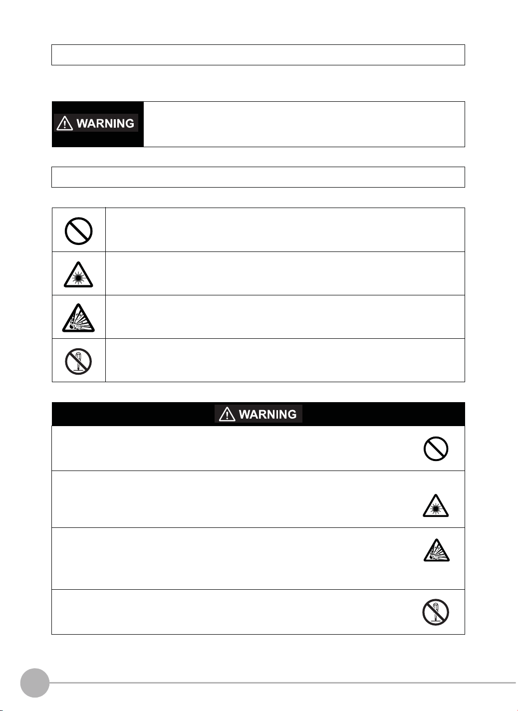
Meanings of Signal Words
The following signal words are used in this manual.
Indicates a potentially hazardous situation which, if not avoided, will result in minor or
moderate injury, or may result in serious injury or death. Additionally there may be
significant property damage.
Meanings of Alert Symbols
The following alert symbols are used in this manual
Indicates general prohibitions for which there is no specific symbol.
Indicates the possibility of laser radiation.
Indicates the possibility of explosion under specific conditions.
Indicates prohibition when there is a risk of minor injury from electrical shock or other
source if the product is disassembled.
This product is not designed or rated for ensuring safety of persons.
Do not use it for such purposes.
The Sensor emits visible light, which may adversely affect the eyes in rare instances.
Do not look directly into the light emitted from the Sensor. When the subject is a specular
reflective object, protect your eyes from reflected light.
A lithium ion battery is built into the Touch Finder and may occasionally combust, explode, or
burn if not treated properly.
Dispose of the Touch Finder as industrial waste, and never disassemble, apply pressure that
would deform, heat to 100 °C or higher, or incinerate the Touch Finder.
High-voltage parts inside; danger of electrical shock. Do not open the product cover.
4
FQ2-S4 User’s Manual
Page 7

Precautions for Safe Use
The following points are important to ensure safety, so make sure that they are strictly observed.
1. Installation Environment
• Do not use the product in environments where it can be exposed to inflammable/explosive gas.
• To secure the safety of operation and maintenance, do not install the product close to high-voltage devices
and power devices.
• Install the product in such a way that its ventilation holes are not blocked.
• Tighten mounting screws at the torque specified in this manual.
2. Power Supply and Wiring
• The power supply voltage must be within the rated range (24 VDC ±10%), and an AC voltage must not be
used.
• Reverse connection of the power supply is not allowed. Do not short the load of the open collector output.
• The load must be within the rated range.
• High-voltage lines and power lines must be wired separately from this product. Wiring them together or
placing them in the same duct may cause induction, resulting in malfunction or damage.
• Use the products within the power supply voltages specified in this manual.
• Use the specified size of crimp terminals to wire connections. Do not connect wires that have been simply
twisted together directly to the power supply or terminal block.
• Use a DC power supply with safety measures against high voltages (safety extra low-voltage circuit).
• Use independent power sources for the products. Do not use a shared power source.
• Tighten mounting screws at the torque specified in this manual.
• Always turn OFF the power supply before connecting or disconnecting cables or the power supply wiring.
3. Battery
• Do not short the positive and negative terminals of the Battery.
• Do not use the Touch Finder in an environment that exceeds the operating temperature range of the Battery.
If the Touch Finder is used at temperatures that exceed the operating temperature range, the protective
device may activate and prevent charging.
• Do not connect the Battery directly to a power supply or car cigarette lighter socket.
• Do not use the Touch Finder with any other type of battery.
• Turn OFF the power supply immediately if the Battery leaks or produces an odor. Electrolyte leaked from the
Battery may ignite, possibly causing smoke, rupture, or fire.
• If during usage, charging, or storage, the Battery produces an odor, heats, becomes discolored, becomes
misshapen, or exhibits any other unusual conditions, remove it and do not use it. Continuing to use such a
Battery may result in the Battery heating, smoking, rupturing, or igniting.
• If the Touch Finder (FQ2-D31) will be installed permanently or semi-permanently, remove the Battery (FQ-
BAT1). If the rated temperature is exceeded with the Battery inserted, the protective circuit may activate and
stop the Touch Finder.
4. AC Adapter
• Use an AC cable that is suitable for the power supply and power voltage you are using.
• Do not touch the power plug with a wet hand. Doing so may result in electrical shock.
• If you notice an abnormal condition, such as smoke, abnormal heating of the outer surface, or a strange
odor, immediately stop using the AC Adapter, turn OFF the power, and remove the power plug from the
outlet.
Consult your dealer, as it is dangerous to attempt to repair the AC Adapter yourself.
• If the AC Adapter is dropped or damaged, turn OFF the power, remove the power plug from the outlet, and
contact your dealer. There is a risk of fire if you continue using the AC Adapter.
FQ2-S4 User’s Manual
5
Page 8

5. Handling
• Connector Cover
Always attach the connector cover when you disconnect the cable. If you do not attach the connector cover,
foreign matter may enter the connection, causing malfunctions or damage.
• Lens Cap
Always attach a C-mount lens cap to the lens mount when you remove the lens. If dust or dirt adhere to the
imaging elements, false detection or failure may occur.
• Sensor Waterproof Sheets
Do not remove or damage the waterproof sheets on the sides of the Sensor. Doing so may allow dust, dirt,
or water drops to enter the Sensor and damage it.
6. Other
• Do not use this product in safety circuits associated with nuclear power and human life.
• Do not disassemble, repair, modify, deform by pressure, or incinerate this product.
• Dispose of this product as industrial waste.
• Connect the special products (Sensor, Touch Finder, Cables). The product might break down or malfunction
if you use a part not included in the special products.
• If you notice an abnormal condition, such as a strange odor, extreme heating of any product, or smoke,
immediately stop using the product, turn OFF the power, and consult your dealer.
• The Sensor surfaces become hot during use. Do not touch them.
• Do not drop or subject the products to shock.
• Use the special Sensor (FQ2-S4), Touch Finder (FQ2-D), Sensor Data Unit (FQ-SDU), Cables (FQ-WN,
FQ-WD, FQ-WU, and FQ-VP), Battery (FQ-BAT1), and AC Adapter (FQ-AC). Using other than the specified
products may cause fire, burning, malfunction or failure.
• If the product has a lock mechanism, always make sure it is locked before using the product.
7. Laws and Regulations, Standards
• This product complies with the following EC Directives and EN Standards:
EC Directive No. IEC61010-1
EN Standards EN61326-1: 2006
6
FQ2-S4 User’s Manual
Page 9
Precautions for Correct Use
Observe the following precautions to prevent failure to operate, malfunctions, or undesirable effects on product
performance.
1. Installation Site
Do not install this product in locations subjected to the following conditions:
• Ambient temperature outside the rating
• Rapid temperature fluctuations (causing condensation)
• Relative humidity outside the range of 35 to 85%
• Direct vibration or shock
• Strong ambient light (such as other laser beams, light from arc-welding machines, or ultraviolet light)
• Direct sunlight or near heaters
• Strong magnetic or electric field
Also, do not install this product in locations subjected to the following conditions to ensure its protective
performance as described in the specifications:
• Presence of corrosive or flammable gases
• Presence of dust, salt, or iron particles
• Water, oil, or chemical fumes or spray, or mist atmospheres
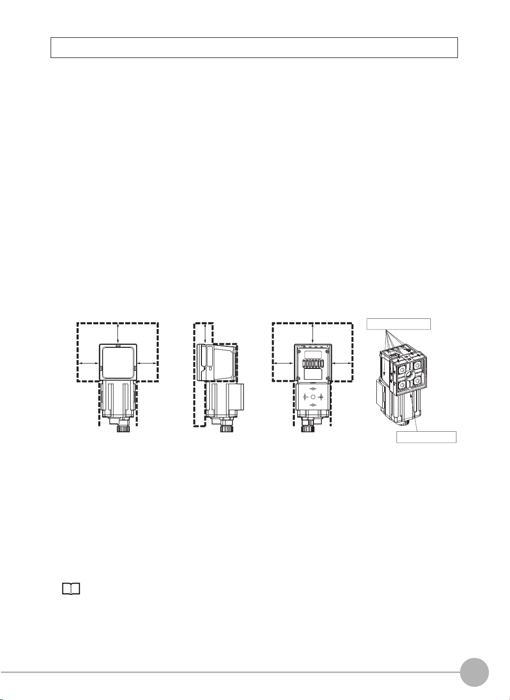
Installing and Using a Sensor with Built-in Lighting
• The front-panel plate may occasionally become fogged from the inside if the Sensor is used in location with
high humidity and the temperature changes drastically.
• Do not install any objects except for the special mounting brackets within the dotted lines in the following
figure. The front-panel plate may become fogged from the inside.
Water-proof Sheet
25 mm25 mm25 mm
25 mm 25 mm
25 mm25 mm
Waterproof sheet
2. Power Supply, Connection, and Wiring
• When using a commercially available switching regulator, make sure that the FG terminal is grounded.
• If surge currents are present in the power lines, connect surge absorbers that suit the operating
environment.
• Before turning ON the power after the product is connected, make sure that the power supply voltage is
correct, there are no incorrect connections (e.g. load short-circuit) and the load current is appropriate.
Incorrect wiring may result in breakdown of the product.
• For cables, use only the special products specified in this manual.
• Do not subject the Cables to twisting stress. Doing so may damage the Cables.
• Always turn OFF the power supply before connecting or disconnecting Cables. The Sensor may fail if a
Cable is connected or disconnected while power is being supplied.
p.565, p.566, p.567, p.568
• Use only combinations of the Sensor and Touch Finder specified in this manual. Using other combinations
may cause malfunction or damage.
• Do not turn the power OFF in the following instances. Doing so will damage data that is in the process of
being saved.
FQ2-S4 User’s Manual
7
Page 10

- While data is being saved in internal memory
- While data is being saved on the SD card
• The LCD panel has been made using precision technology, and sometimes a few pixels are missing in the
panel. This is due to the structure of the LCD panel, and is not a malfunction.
• Influence of Temperature Changes on Optical Axis
Due to the characteristics of the materials that are used in the Sensor, changes in the ambient temperature
may cause the center of the optical axis to change by several pixels.
• Imaging Elements
Due to the specifications of the CMOS image sensors that are used in the Vision Sensor, lines may appear
in images for some measurement conditions or gain settings. These do not indicate defects or faults in the
Vision Sensor. Also, there may be some pixel defects, but these do not indicate defects or faults in the
Vision Sensor.
3. Battery
• Do not use or charge the Battery with other than the specified products.
• Do not charge the Battery with other than the specified AC adapter.
• When using the Touch Finder, the battery cover screw must be tightened.
4. AC Adapter
• During maintenance and when not using the Touch Finder for an extended time, remove the power plug
from the outlet.
• Do not bend the power cable past its natural bending radius.
• Do not use the AC Adapter with other than the specified products.
• If a voltage higher than 380 V is applied, there is a risk that the capacitor will be damaged, the pressure
valve will open, and vaporized gas will be emitted. If there is a possibility that a voltage higher than 380 V
will be applied, use a protective device.
5. Maintenance and Inspection
Do not use thinner, benzene, acetone or kerosene to clean the Sensor and Touch Finder. If large dust particles
adhere to the Camera, use a blower brush (used to clean camera lenses) to blow them off. Do not use breath
from your mouth to blow the dust off. To remove dust particles from the Camera, wipe gently with a soft cloth
(for cleaning lenses) moistened with a small amount of alcohol. Do not use excessive force to wipe off dust
particles. Scratches to the Camera might cause error.
Editor's Note
■ Meaning of Symbols
Menu items that are displayed on the Touch Finder LCD screen, and windows, dialog boxes and other GUI
elements displayed on the PC are indicated enclosed by brackets "[ ]".
■ Visual Aids
Important
Note
Indicates points that are important to achieve the full product performance,
such as operational precautions.
Indicates application procedures.
Indicates pages where related information can be found.
8
FQ2-S4 User’s Manual
Page 11

Table of Contents
1. Introduction
1-1 FQ2-S4-series Vision Sensors . . . . . . . . . . . . . . . . . . . . . . . . . . . . . . . . . . 20
1-2 Measurement Process . . . . . . . . . . . . . . . . . . . . . . . . . . . . . . . . . . . . . . . . 21
1-3 Startup Display and Display Elements . . . . . . . . . . . . . . . . . . . . . . . . . . . 22
Startup Display . . . . . . . . . . . . . . . . . . . . . . . . . . . . . . . . . . . . . . . . . . . . . . . . . 22
Display Elements . . . . . . . . . . . . . . . . . . . . . . . . . . . . . . . . . . . . . . . . . . . . . . . . 23
1-4 Basic Operational Flow. . . . . . . . . . . . . . . . . . . . . . . . . . . . . . . . . . . . . . . . 24
2. Installation and Connections
2-1 System Configuration. . . . . . . . . . . . . . . . . . . . . . . . . . . . . . . . . . . . . . . . . 26
2-2 Part Names and Functions. . . . . . . . . . . . . . . . . . . . . . . . . . . . . . . . . . . . . 29
2-3 Installation . . . . . . . . . . . . . . . . . . . . . . . . . . . . . . . . . . . . . . . . . . . . . . . . . . 33
FQ2-S4@@@@@ (Sensors with Built-in Lighting) . . . . . . . . . . . . . . . . . . . . . . . 33
FQ2-S4@-@@@ (Sensors with C-mounts) . . . . . . . . . . . . . . . . . . . . . . . . . . . . 34
Installation Precautions . . . . . . . . . . . . . . . . . . . . . . . . . . . . . . . . . . . . . . . . . . . 38
Mounting to DIN Track . . . . . . . . . . . . . . . . . . . . . . . . . . . . . . . . . . . . . . . . . . . 39
Mounting to a Control Panel . . . . . . . . . . . . . . . . . . . . . . . . . . . . . . . . . . . . . . . 39
Using the Touch Finder as a Portable Device (with Battery) . . . . . . . . . . . . . . .40
Mounting to DIN Track . . . . . . . . . . . . . . . . . . . . . . . . . . . . . . . . . . . . . . . . . . . 41
2-4 Wiring . . . . . . . . . . . . . . . . . . . . . . . . . . . . . . . . . . . . . . . . . . . . . . . . . . . . . . 42
I/O Signal Circuit Diagrams . . . . . . . . . . . . . . . . . . . . . . . . . . . . . . . . . . . . . . . . 43
Power Supply Specifications When a Switching Regulator Is Connected . . . . 43
Attaching the LED Warning Label . . . . . . . . . . . . . . . . . . . . . . . . . . . . . . . . . . .43
2-5 Setting Up Ethernet. . . . . . . . . . . . . . . . . . . . . . . . . . . . . . . . . . . . . . . . . . . 53
Connecting to Sensors from the Touch Finder . . . . . . . . . . . . . . . . . . . . . . . . . 53
Connecting to Sensors from External Devices Such as PLCs . . . . . . . . . . . . . 54
Connecting to Sensors from a Computer Using the PC Tool . . . . . . . . . . . . . . 54
Table of Contents
3. Taking Images
3-1 Selecting a Sensor for Configuration . . . . . . . . . . . . . . . . . . . . . . . . . . . . 58
3-2 Setting Conditions for Taking Images. . . . . . . . . . . . . . . . . . . . . . . . . . . . 59
FQ2-S4 User’s Manual
9
Page 12

3-3 Adjusting Image Quality . . . . . . . . . . . . . . . . . . . . . . . . . . . . . . . . . . . . . . . 60
Adjusting the Focus . . . . . . . . . . . . . . . . . . . . . . . . . . . . . . . . . . . . . . . . . . . . . . 60
Adjusting Image Brightness with External Lighting . . . . . . . . . . . . . . . . . . . . . . 61
Adjusting the Brightness . . . . . . . . . . . . . . . . . . . . . . . . . . . . . . . . . . . . . . . . . . 61
Taking Clear Images of Moving Objects . . . . . . . . . . . . . . . . . . . . . . . . . . . . . . 64
Improving the Image Quality of Metallic and other Shiny Surfaces . . . . . . . . . . 65
Adjusting the Colors of the Image (White Balance)
(Only for Sensors with Color Cameras) . . . . . . . . . . . . . . . . . . . . . . . . . . . . . . . 66
3-4 Adjusting the Timing of Taking Images . . . . . . . . . . . . . . . . . . . . . . . . . . 67
Delaying the Image Capture Timing from the Trigger Input . . . . . . . . . . . . . . . 67
Adjusting External Lighting Timing . . . . . . . . . . . . . . . . . . . . . . . . . . . . . . . . . . 68
Preventing Mutual Interference of Multiple Sensors . . . . . . . . . . . . . . . . . . . . . 68
3-5 Adjusting the Images That Were Taken . . . . . . . . . . . . . . . . . . . . . . . . . . 69
Image Adjustment . . . . . . . . . . . . . . . . . . . . . . . . . . . . . . . . . . . . . . . . . . . . . . . 69
Filtering the Images (Filter Items) . . . . . . . . . . . . . . . . . . . . . . . . . . . . . . . . . . . 70
Compensating for Position Offset (Position Compensation Items) . . . . . . . . . .75
Edge Rotation Position Compensation . . . . . . . . . . . . . . . . . . . . . . . . . . . . . . . 86
4. Setting Up Inspections
4-1 Inspection Item Selection Guide . . . . . . . . . . . . . . . . . . . . . . . . . . . . . . . . 90
4-2 Setup Procedure for Inspection Items . . . . . . . . . . . . . . . . . . . . . . . . . . . 93
4-3 Configuring Inspection Items. . . . . . . . . . . . . . . . . . . . . . . . . . . . . . . . . . . 94
Adding New Inspection Items . . . . . . . . . . . . . . . . . . . . . . . . . . . . . . . . . . . . . . 94
Modifying Existing Inspection Items . . . . . . . . . . . . . . . . . . . . . . . . . . . . . . . . . 95
Deleting Inspection Items . . . . . . . . . . . . . . . . . . . . . . . . . . . . . . . . . . . . . . . . . 95
4-4 Reading and Verifying Character Strings . . . . . . . . . . . . . . . . . . . . . . . . . 96
Character String Recognition . . . . . . . . . . . . . . . . . . . . . . . . . . . . . . . . . . . . . . 96
Characters That Can Be Recognized . . . . . . . . . . . . . . . . . . . . . . . . . . . . . . . . 96
Setup Procedure for Character Recognition . . . . . . . . . . . . . . . . . . . . . . . . . . . 97
Setup Procedure for Character Recognition . . . . . . . . . . . . . . . . . . . . . . . . . . . 97
Setting the Measurement Parameters . . . . . . . . . . . . . . . . . . . . . . . . . . . . . . . 103
Changing the Output Code for Errors (Default: NG) . . . . . . . . . . . . . . . . . . . .104
Troubleshooting Unstable Read Results . . . . . . . . . . . . . . . . . . . . . . . . . . . . .104
Using Model Dictionaries to Recognize Custom Characters . . . . . . . . . . . . . .105
Outputting Read Characters to an External Device . . . . . . . . . . . . . . . . . . . . 110
Measurement Data That Can Be Used for External Outputs and Calculations 110
Measurement Data That Can Be Logged for OCR . . . . . . . . . . . . . . . . . . . . . 111
Failure to Read Characters . . . . . . . . . . . . . . . . . . . . . . . . . . . . . . . . . . . . . . . 111
4-5 Reading Bar Codes . . . . . . . . . . . . . . . . . . . . . . . . . . . . . . . . . . . . . . . . . . 112
Bar Codes . . . . . . . . . . . . . . . . . . . . . . . . . . . . . . . . . . . . . . . . . . . . . . . . . . . . 112
Setup Procedure for Bar Code . . . . . . . . . . . . . . . . . . . . . . . . . . . . . . . . . . . . 113
Reflect in Total Judgement . . . . . . . . . . . . . . . . . . . . . . . . . . . . . . . . . . . . . . . 116
Detail Settings . . . . . . . . . . . . . . . . . . . . . . . . . . . . . . . . . . . . . . . . . . . . . . . . . 116
10
FQ2-S4 User’s Manual
Page 13

Outputting Read Characters to an External Device . . . . . . . . . . . . . . . . . . . . 117
Changing the Character String That Is Output for Read Errors . . . . . . . . . . . 117
Changing the Items That Are Displayed on the Test Measurement
and Run Display . . . . . . . . . . . . . . . . . . . . . . . . . . . . . . . . . . . . . . . . . . . . . . . 118
Unstable Reading Results . . . . . . . . . . . . . . . . . . . . . . . . . . . . . . . . . . . . . . . . 118
Measurement Data That Can Be Used for External Outputs and Calculations 118
Measurement Data That Can Be Logged (Bar Code) . . . . . . . . . . . . . . . . . . .119
Errors . . . . . . . . . . . . . . . . . . . . . . . . . . . . . . . . . . . . . . . . . . . . . . . . . . . . . . . . 119
4-6 Reading 2D-codes. . . . . . . . . . . . . . . . . . . . . . . . . . . . . . . . . . . . . . . . . . . 120
2D-codes . . . . . . . . . . . . . . . . . . . . . . . . . . . . . . . . . . . . . . . . . . . . . . . . . . . . . 120
Setup Procedure for 2D-code . . . . . . . . . . . . . . . . . . . . . . . . . . . . . . . . . . . . .121
Reflect in Total Judgement . . . . . . . . . . . . . . . . . . . . . . . . . . . . . . . . . . . . . . . 125
Detail Settings . . . . . . . . . . . . . . . . . . . . . . . . . . . . . . . . . . . . . . . . . . . . . . . . . 125
Outputting Read Characters to an External Device . . . . . . . . . . . . . . . . . . . . 125
Changing the Character String That Is Output for Read Errors . . . . . . . . . . . 126
Changing the Items That Are Displayed on the Test Measurement
and Run Display . . . . . . . . . . . . . . . . . . . . . . . . . . . . . . . . . . . . . . . . . . . . . . . 126
Unstable Reading Results . . . . . . . . . . . . . . . . . . . . . . . . . . . . . . . . . . . . . . . . 126
Measurement Data That Can Be Used for External Outputs and Calculations 127
Measurement Data That Can Be Logged (2D Code) . . . . . . . . . . . . . . . . . . . 127
Errors . . . . . . . . . . . . . . . . . . . . . . . . . . . . . . . . . . . . . . . . . . . . . . . . . . . . . . . . 127
4-7 Reading DPM 2D Codes . . . . . . . . . . . . . . . . . . . . . . . . . . . . . . . . . . . . . . 128
2D Codes (DPM) . . . . . . . . . . . . . . . . . . . . . . . . . . . . . . . . . . . . . . . . . . . . . . .128
Setup Procedure for 2D-code (DPM) . . . . . . . . . . . . . . . . . . . . . . . . . . . . . . .128
Detailed Parameters . . . . . . . . . . . . . . . . . . . . . . . . . . . . . . . . . . . . . . . . . . . . 133
Outputting Read Characters to an External Device . . . . . . . . . . . . . . . . . . . . 134
Changing the Character String That Is Output for Read Errors . . . . . . . . . . . 135
Measurement Data That Can Be Used for External Outputs and Calculations 135
Inspection Data that Can be Logged . . . . . . . . . . . . . . . . . . . . . . . . . . . . . . . .135
If an Error Occurs . . . . . . . . . . . . . . . . . . . . . . . . . . . . . . . . . . . . . . . . . . . . . . 136
4-8 Inspecting with the Search Inspection Item . . . . . . . . . . . . . . . . . . . . . . 137
Search Inspection Item . . . . . . . . . . . . . . . . . . . . . . . . . . . . . . . . . . . . . . . . . . 137
Setup Procedure for the Search Inspection Item . . . . . . . . . . . . . . . . . . . . . .137
Increasing Measurement Position Accuracy . . . . . . . . . . . . . . . . . . . . . . . . . . 139
Obtaining Multiple Results Simultaneously . . . . . . . . . . . . . . . . . . . . . . . . . . .139
Select the Results to Output . . . . . . . . . . . . . . . . . . . . . . . . . . . . . . . . . . . . . . 140
Reflect in Total Judgement . . . . . . . . . . . . . . . . . . . . . . . . . . . . . . . . . . . . . . . 140
Unstable Search Results . . . . . . . . . . . . . . . . . . . . . . . . . . . . . . . . . . . . . . . . . 141
Increasing Processing Speed . . . . . . . . . . . . . . . . . . . . . . . . . . . . . . . . . . . . . 141
Editing the Model and Measurement Regions . . . . . . . . . . . . . . . . . . . . . . . .142
Errors . . . . . . . . . . . . . . . . . . . . . . . . . . . . . . . . . . . . . . . . . . . . . . . . . . . . . . . . 146
4-9 Inspecting with the Shape Search II Inspection Item. . . . . . . . . . . . . . . 147
Shape Search II Inspection Item . . . . . . . . . . . . . . . . . . . . . . . . . . . . . . . . . . . 147
Setup Procedure for the Shape Search II Inspection Item . . . . . . . . . . . . . . . 147
FQ2-S4 User’s Manual
11
Page 14

Obtaining Multiple Results Simultaneously . . . . . . . . . . . . . . . . . . . . . . . . . . .149
Select the Results to Output . . . . . . . . . . . . . . . . . . . . . . . . . . . . . . . . . . . . . . 150
Reflect in Total Judgement . . . . . . . . . . . . . . . . . . . . . . . . . . . . . . . . . . . . . . . 150
Unstable Shape Search II Results . . . . . . . . . . . . . . . . . . . . . . . . . . . . . . . . .151
Increasing Processing Speed . . . . . . . . . . . . . . . . . . . . . . . . . . . . . . . . . . . . . 152
Editing the Model Regions and Measurement Region . . . . . . . . . . . . . . . . . . 152
Errors . . . . . . . . . . . . . . . . . . . . . . . . . . . . . . . . . . . . . . . . . . . . . . . . . . . . . . . . 154
4-10 Inspecting with the Sensitive Search Inspection Item. . . . . . . . . . . . . . 155
Sensitive Search Inspection Item . . . . . . . . . . . . . . . . . . . . . . . . . . . . . . . . . . 155
Setup Procedure for the Sensitive Search Inspection Item . . . . . . . . . . . . . . . 155
Reflect in Total Judgement . . . . . . . . . . . . . . . . . . . . . . . . . . . . . . . . . . . . . . . 157
Increasing Measurement Position Accuracy . . . . . . . . . . . . . . . . . . . . . . . . . . 157
Select the Results to Output . . . . . . . . . . . . . . . . . . . . . . . . . . . . . . . . . . . . . . 157
Changing the Number Region Divisions . . . . . . . . . . . . . . . . . . . . . . . . . . . . . 158
Inspecting Plain Regions . . . . . . . . . . . . . . . . . . . . . . . . . . . . . . . . . . . . . . . . . 158
Unstable Search Results . . . . . . . . . . . . . . . . . . . . . . . . . . . . . . . . . . . . . . . . . 158
Increasing Processing Speed . . . . . . . . . . . . . . . . . . . . . . . . . . . . . . . . . . . . . 159
Editing the Model Regions and Measurement Region . . . . . . . . . . . . . . . . . . 159
Errors . . . . . . . . . . . . . . . . . . . . . . . . . . . . . . . . . . . . . . . . . . . . . . . . . . . . . . . . 161
4-11 Inspecting with the Edge Position Inspection Item . . . . . . . . . . . . . . . . 162
Edge Position . . . . . . . . . . . . . . . . . . . . . . . . . . . . . . . . . . . . . . . . . . . . . . . . . 162
Setup Procedure for Edge Position . . . . . . . . . . . . . . . . . . . . . . . . . . . . . . . . . 162
Reflect in Total Judgement . . . . . . . . . . . . . . . . . . . . . . . . . . . . . . . . . . . . . . . 164
Changing Edge Detection Conditions
(Sensors with Monochrome Cameras Only) . . . . . . . . . . . . . . . . . . . . . . . . . . 164
Unstable Edge Position Results . . . . . . . . . . . . . . . . . . . . . . . . . . . . . . . . . . . 164
Increasing Processing Speed for Edge Position . . . . . . . . . . . . . . . . . . . . . . . 167
Measurement Data That Can Be Used for External Outputs and Calculations 167
Measurement Data That Can Be Logged for Edge Position . . . . . . . . . . . . . . 167
Errors . . . . . . . . . . . . . . . . . . . . . . . . . . . . . . . . . . . . . . . . . . . . . . . . . . . . . . . . 168
4-12 Inspecting with the Edge Width Inspection Item . . . . . . . . . . . . . . . . . . 169
Edge Width Inspection Item . . . . . . . . . . . . . . . . . . . . . . . . . . . . . . . . . . . . . . 169
Setup Procedure for Edge Width Inspection Item . . . . . . . . . . . . . . . . . . . . . . 169
Changing Edge Detection Conditions
(Sensors with Monochrome Cameras Only) . . . . . . . . . . . . . . . . . . . . . . . . . . 171
Reflect in Total Judgement . . . . . . . . . . . . . . . . . . . . . . . . . . . . . . . . . . . . . . . 171
Unstable Edge Width Results (Sensors with Color Cameras) . . . . . . . . . . . . 171
Increasing Edge Width Processing Speed . . . . . . . . . . . . . . . . . . . . . . . . . . .171
Measurement Data That Can Be Used for External Outputs and Calculations 171
Measurement Data That Can Be Logged for Edge Width . . . . . . . . . . . . . . . . 172
Errors . . . . . . . . . . . . . . . . . . . . . . . . . . . . . . . . . . . . . . . . . . . . . . . . . . . . . . . . 172
4-13 Inspecting with the Edge Pitch Inspection Item. . . . . . . . . . . . . . . . . . . 173
Edge Pitch Inspection Item . . . . . . . . . . . . . . . . . . . . . . . . . . . . . . . . . . . . . . . 173
Setup Procedure for Edge Width Inspection Item . . . . . . . . . . . . . . . . . . . . . . 173
12
FQ2-S4 User’s Manual
Page 15

Changing Edge Detection Conditions
(Sensors with Monochrome Cameras Only) . . . . . . . . . . . . . . . . . . . . . . . . . . 175
Reflect in Total Judgement . . . . . . . . . . . . . . . . . . . . . . . . . . . . . . . . . . . . . . . 175
Unstable Edge Pitch Results (Sensors with Color Cameras Only) . . . . . . . . . 175
Increasing Edge Pitch Processing Speed . . . . . . . . . . . . . . . . . . . . . . . . . . . . 175
Measurement Data That Can Be Used for External Outputs and Calculations 176
Measurement Data That Can Be Logged for Edge Pitch . . . . . . . . . . . . . . . . 176
Errors . . . . . . . . . . . . . . . . . . . . . . . . . . . . . . . . . . . . . . . . . . . . . . . . . . . . . . . . 176
4-14 Inspecting with Color Data Inspection Item . . . . . . . . . . . . . . . . . . . . . . 178
Color Data Inspection Item . . . . . . . . . . . . . . . . . . . . . . . . . . . . . . . . . . . . . . . 178
Setup Procedure for Color Data Inspection Item . . . . . . . . . . . . . . . . . . . . . . .178
Reflect in Total Judgement . . . . . . . . . . . . . . . . . . . . . . . . . . . . . . . . . . . . . . . 180
Measurement Data That Can Be Used for External Outputs and Calculations 180
Measurement Data That Can Be Logged (Color Data) . . . . . . . . . . . . . . . . . .181
Increasing Processing Speed for Color Data . . . . . . . . . . . . . . . . . . . . . . . . . 181
4-15 Inspecting with the Area Inspection Item . . . . . . . . . . . . . . . . . . . . . . . . 182
Area Inspection Item . . . . . . . . . . . . . . . . . . . . . . . . . . . . . . . . . . . . . . . . . . . . 182
Setup Procedure for Area . . . . . . . . . . . . . . . . . . . . . . . . . . . . . . . . . . . . . . . .182
Reflect in Total Judgement . . . . . . . . . . . . . . . . . . . . . . . . . . . . . . . . . . . . . . . 184
Unstable Area Results . . . . . . . . . . . . . . . . . . . . . . . . . . . . . . . . . . . . . . . . . . . 184
Changing the Area Detection Conditions . . . . . . . . . . . . . . . . . . . . . . . . . . . . 186
Increasing Processing Speed for Area . . . . . . . . . . . . . . . . . . . . . . . . . . . . . . 186
Measurement Data That Can Be Used for External Outputs and Calculations 187
Measurement Data That Can Be Logged for Area . . . . . . . . . . . . . . . . . . . . . 187
Errors . . . . . . . . . . . . . . . . . . . . . . . . . . . . . . . . . . . . . . . . . . . . . . . . . . . . . . . . 187
4-16 Inspecting with the Labeling Inspection Item. . . . . . . . . . . . . . . . . . . . . 188
Labeling . . . . . . . . . . . . . . . . . . . . . . . . . . . . . . . . . . . . . . . . . . . . . . . . . . . . . . 188
Setup Procedure for Labeling Inspection Item . . . . . . . . . . . . . . . . . . . . . . . . 188
Unstable Labeling Results . . . . . . . . . . . . . . . . . . . . . . . . . . . . . . . . . . . . . . . . 190
Changing the Label Detection Conditions . . . . . . . . . . . . . . . . . . . . . . . . . . . . 192
Changing the Label Extraction Conditions . . . . . . . . . . . . . . . . . . . . . . . . . . . 193
Sorting Extracted Labels . . . . . . . . . . . . . . . . . . . . . . . . . . . . . . . . . . . . . . . . . 193
Reflect in Total Judgement . . . . . . . . . . . . . . . . . . . . . . . . . . . . . . . . . . . . . . . 194
Editing the Measurement Region . . . . . . . . . . . . . . . . . . . . . . . . . . . . . . . . . . 194
Increasing the Processing Speed . . . . . . . . . . . . . . . . . . . . . . . . . . . . . . . . . . 195
Measurement Data That Can Be Used for External Outputs and Calculations 195
Measurement Data That Can Be Logged for Labeling . . . . . . . . . . . . . . . . . . 196
Errors . . . . . . . . . . . . . . . . . . . . . . . . . . . . . . . . . . . . . . . . . . . . . . . . . . . . . . . . 196
4-17 Calculations and Judgements Using Inspection Item Data . . . . . . . . . 197
Calculation . . . . . . . . . . . . . . . . . . . . . . . . . . . . . . . . . . . . . . . . . . . . . . . . . . . . 197
Examples for Calculation . . . . . . . . . . . . . . . . . . . . . . . . . . . . . . . . . . . . . . . . . 199
Procedure (Calculation) . . . . . . . . . . . . . . . . . . . . . . . . . . . . . . . . . . . . . . . . . . 199
Function List . . . . . . . . . . . . . . . . . . . . . . . . . . . . . . . . . . . . . . . . . . . . . . . . . . 201
FQ2-S4 User’s Manual
13
Page 16

5. Testing and Saving Settings
5-1 Performing Test Measurements. . . . . . . . . . . . . . . . . . . . . . . . . . . . . . . . 214
Performing Test Measurements with Samples . . . . . . . . . . . . . . . . . . . . . . . . 214
Performing Test Measurements with Saved Images (Re-measuring) . . . . . . .214
5-2 Shortening the Measurement Takt Time. . . . . . . . . . . . . . . . . . . . . . . . . 216
Checking the Measurement Takt Time . . . . . . . . . . . . . . . . . . . . . . . . . . . . . . 216
Increasing Image Input Speed . . . . . . . . . . . . . . . . . . . . . . . . . . . . . . . . . . . .217
Changing the Image Input Mode . . . . . . . . . . . . . . . . . . . . . . . . . . . . . . . . . . . 218
5-3 Adjusting the Judgement Parameters. . . . . . . . . . . . . . . . . . . . . . . . . . . 219
Adjusting Judgement Parameters While Looking at Measurement Results . .219
Setting Up the Best Judgement Parameters Automatically . . . . . . . . . . . . . . .219
5-4 Checking a List of All Inspection Item Results . . . . . . . . . . . . . . . . . . . 221
5-5 Saving Data to the Sensor . . . . . . . . . . . . . . . . . . . . . . . . . . . . . . . . . . . . 222
6. Operation
6-1 Starting Operation. . . . . . . . . . . . . . . . . . . . . . . . . . . . . . . . . . . . . . . . . . . 224
Run Mode Display . . . . . . . . . . . . . . . . . . . . . . . . . . . . . . . . . . . . . . . . . . . . . . 224
Moving to Run Mode . . . . . . . . . . . . . . . . . . . . . . . . . . . . . . . . . . . . . . . . . . . . 224
6-2 Configuring the Run Mode Display . . . . . . . . . . . . . . . . . . . . . . . . . . . . . 226
6-3 Checking the Trend of Measurement Results with Graphs . . . . . . . . . 228
Trend Monitor . . . . . . . . . . . . . . . . . . . . . . . . . . . . . . . . . . . . . . . . . . . . . . . . .228
Histograms . . . . . . . . . . . . . . . . . . . . . . . . . . . . . . . . . . . . . . . . . . . . . . . . . . . 229
6-4 Adjusting Judgement Parameters during Operation. . . . . . . . . . . . . . . 231
Preparations . . . . . . . . . . . . . . . . . . . . . . . . . . . . . . . . . . . . . . . . . . . . . . . . . . 231
Changing the Judgement Parameters in Run Mode . . . . . . . . . . . . . . . . . . . . 231
7. Convenient Functions
7-1 Changing the Scene to Change the Line Process . . . . . . . . . . . . . . . . . 234
What Are Scenes? . . . . . . . . . . . . . . . . . . . . . . . . . . . . . . . . . . . . . . . . . . . . . 234
Creating New Scenes . . . . . . . . . . . . . . . . . . . . . . . . . . . . . . . . . . . . . . . . . . .235
Changing Scene Names, Copying Scenes, and Deleting Scenes . . . . . . . . . 235
Switching Scenes from an External Device . . . . . . . . . . . . . . . . . . . . . . . . . . . 235
Setting the Startup Scene . . . . . . . . . . . . . . . . . . . . . . . . . . . . . . . . . . . . . . . . 236
7-2 Calibration . . . . . . . . . . . . . . . . . . . . . . . . . . . . . . . . . . . . . . . . . . . . . . . . . 237
Calibration . . . . . . . . . . . . . . . . . . . . . . . . . . . . . . . . . . . . . . . . . . . . . . . . . . . . 237
Setting the Calibration Pattern . . . . . . . . . . . . . . . . . . . . . . . . . . . . . . . . . . . . 238
Selecting the Calibration Pattern to Use . . . . . . . . . . . . . . . . . . . . . . . . . . . . . 243
7-3 Display Functions . . . . . . . . . . . . . . . . . . . . . . . . . . . . . . . . . . . . . . . . . . . 244
Image Zoom . . . . . . . . . . . . . . . . . . . . . . . . . . . . . . . . . . . . . . . . . . . . . . . . . . 244
Displaying a Live Image . . . . . . . . . . . . . . . . . . . . . . . . . . . . . . . . . . . . . . . . . 244
Displaying a Frozen Image . . . . . . . . . . . . . . . . . . . . . . . . . . . . . . . . . . . . . . . 244
14
FQ2-S4 User’s Manual
Page 17

Displaying a Saved Image . . . . . . . . . . . . . . . . . . . . . . . . . . . . . . . . . . . . . . . . 245
Updating the Display and Measurement Results
Only for NG Measurement Results . . . . . . . . . . . . . . . . . . . . . . . . . . . . . . . . . 245
Automatically Changing to the Display for Any Sensor with an NG Result . . . 246
Hiding the Menu . . . . . . . . . . . . . . . . . . . . . . . . . . . . . . . . . . . . . . . . . . . . . . . 246
Turning ON/OFF the Touch Finder Backlight . . . . . . . . . . . . . . . . . . . . . . . . . 246
Changing the Brightness of the Touch Finder . . . . . . . . . . . . . . . . . . . . . . . . . 246
7-4 Monitoring the Signal I/O Status . . . . . . . . . . . . . . . . . . . . . . . . . . . . . . . 247
7-5 Connecting to More Than One Sensor . . . . . . . . . . . . . . . . . . . . . . . . . . 248
Setting the Sensors to Connect . . . . . . . . . . . . . . . . . . . . . . . . . . . . . . . . . . . . 248
Selecting the Display When More Than One Sensor Is Connected . . . . . . . .250
7-6 Logging Measurement Data and Image Data . . . . . . . . . . . . . . . . . . . . . 252
Logging Procedure . . . . . . . . . . . . . . . . . . . . . . . . . . . . . . . . . . . . . . . . . . . . .252
Logging All Data (File Logging) . . . . . . . . . . . . . . . . . . . . . . . . . . . . . . . . . . . .253
Checking Recent Measurement Trends (Recent Results Logging) . . . . . . . . 258
7-7 Saving Sensor Settings . . . . . . . . . . . . . . . . . . . . . . . . . . . . . . . . . . . . . . 262
Backing Up Settings in External Memory . . . . . . . . . . . . . . . . . . . . . . . . . . . . 262
Restoring Data to the Sensor from External Memory . . . . . . . . . . . . . . . . . . . 263
7-8 SD Card Operations . . . . . . . . . . . . . . . . . . . . . . . . . . . . . . . . . . . . . . . . . 264
Inserting and Removing SD Cards . . . . . . . . . . . . . . . . . . . . . . . . . . . . . . . . . 265
Checking the Available Space on the SD Card . . . . . . . . . . . . . . . . . . . . . . . . 266
Formatting an SD Card . . . . . . . . . . . . . . . . . . . . . . . . . . . . . . . . . . . . . . . . . . 266
7-9 Convenient Functions for Operation. . . . . . . . . . . . . . . . . . . . . . . . . . . . 267
Setting a Password to Prevent Unwanted Changes . . . . . . . . . . . . . . . . . . . .267
Capturing the Displayed Image . . . . . . . . . . . . . . . . . . . . . . . . . . . . . . . . . . . . 268
Saving the Currently Displayed Camera Image . . . . . . . . . . . . . . . . . . . . . . . 268
Setting the Startup Run Display Pattern . . . . . . . . . . . . . . . . . . . . . . . . . . . . . 269
Specifying the Sensors to Connect Continuously . . . . . . . . . . . . . . . . . . . . . .269
Monitoring and Setting Up a Sensor from Two Touch Finders . . . . . . . . . . . . 269
7-10 Convenient Functions for Setup . . . . . . . . . . . . . . . . . . . . . . . . . . . . . . . 271
Making Settings with Stored Images . . . . . . . . . . . . . . . . . . . . . . . . . . . . . . . . 271
7-11 Setting the Retry Function . . . . . . . . . . . . . . . . . . . . . . . . . . . . . . . . . . . . 273
Retry Function . . . . . . . . . . . . . . . . . . . . . . . . . . . . . . . . . . . . . . . . . . . . . . . . . 273
7-12 Functions Related to the System. . . . . . . . . . . . . . . . . . . . . . . . . . . . . . . 277
Turning OFF the Integrated Sensor Lighting
(Only Sensors with Built-in Lighting) . . . . . . . . . . . . . . . . . . . . . . . . . . . . . . . . 277
Switching the Display Language . . . . . . . . . . . . . . . . . . . . . . . . . . . . . . . . . . . 277
Setting the Time on the Touch Finder . . . . . . . . . . . . . . . . . . . . . . . . . . . . . . . 277
Initializing the Sensor and Touch Finder . . . . . . . . . . . . . . . . . . . . . . . . . . . . . 277
Restarting the Sensor and Touch Finder . . . . . . . . . . . . . . . . . . . . . . . . . . . . 277
Checking Versions . . . . . . . . . . . . . . . . . . . . . . . . . . . . . . . . . . . . . . . . . . . . . 277
Checking the Touch Finder Battery Level . . . . . . . . . . . . . . . . . . . . . . . . . . . . 278
Changing the Sensor Name . . . . . . . . . . . . . . . . . . . . . . . . . . . . . . . . . . . . . . 278
FQ2-S4 User’s Manual
15
Page 18

Checking Available Memory in the Sensor . . . . . . . . . . . . . . . . . . . . . . . . . . . 278
Correcting the Touch Screen Positions of the Touch Finder . . . . . . . . . . . . . .278
Setting the Resolution of Measurement Objects Displayed on the PC Tool . . 278
Rotating the Touch Finder Image by 180× . . . . . . . . . . . . . . . . . . . . . . . . . . . 278
Changing the Sensor’s BUSY Indicator . . . . . . . . . . . . . . . . . . . . . . . . . . . . . 278
Setting the Inspection Timeout Time . . . . . . . . . . . . . . . . . . . . . . . . . . . . . . . .278
8. Controlling Operation and Outputting Data
with a Parallel Connection
8-1 Controlling Operation and Outputting Data
with the Sensor's Standard Parallel Connection . . . . . . . . . . . . . . . . . . 280
Basic Operation with a Parallel Connection . . . . . . . . . . . . . . . . . . . . . . . . . . 280
Setting the Measurement Trigger . . . . . . . . . . . . . . . . . . . . . . . . . . . . . . . . . . 281
Setting the Outputs . . . . . . . . . . . . . . . . . . . . . . . . . . . . . . . . . . . . . . . . . . . . . 286
Controlling the Sensor from an External Device . . . . . . . . . . . . . . . . . . . . . . . 292
8-2 Controlling Operation and Outputting Data
with a Parallel Interface Sensor Data Unit . . . . . . . . . . . . . . . . . . . . . . . 302
Overview . . . . . . . . . . . . . . . . . . . . . . . . . . . . . . . . . . . . . . . . . . . . . . . . . . . . . 302
Setting the Measurement Trigger . . . . . . . . . . . . . . . . . . . . . . . . . . . . . . . . . . 302
Setting Output Data . . . . . . . . . . . . . . . . . . . . . . . . . . . . . . . . . . . . . . . . . . . . . 303
Aligning the Data Output Timing with the External Device . . . . . . . . . . . . . . . 308
Changing the Settings of the I/O Signals . . . . . . . . . . . . . . . . . . . . . . . . . . . . 316
Controlling Operation from an External Device . . . . . . . . . . . . . . . . . . . . . . . . 317
9. Connecting through Ethernet
9-1 Introduction . . . . . . . . . . . . . . . . . . . . . . . . . . . . . . . . . . . . . . . . . . . . . . . . 328
9-2 Outputting Data and Controlling Operation through EtherNet/IP. . . . . 329
Introduction to EtherNet/IP . . . . . . . . . . . . . . . . . . . . . . . . . . . . . . . . . . . . . . . 329
FQ2 Communications for EtherNet/IP Connections . . . . . . . . . . . . . . . . . . . . 331
Setting Up EtherNet/IP Communications . . . . . . . . . . . . . . . . . . . . . . . . . . . . 335
Tag Data Link Setting Methods . . . . . . . . . . . . . . . . . . . . . . . . . . . . . . . . . . . .338
Setting the Data To Output Automatically after Measurements . . . . . . . . . . .341
Memory Assignments and Commands . . . . . . . . . . . . . . . . . . . . . . . . . . . . . .348
Timing Chart for EtherNet/IP Communications . . . . . . . . . . . . . . . . . . . . . . . . 366
Sample Ladder Programming . . . . . . . . . . . . . . . . . . . . . . . . . . . . . . . . . . . . . 371
9-3 PLC Link Connections . . . . . . . . . . . . . . . . . . . . . . . . . . . . . . . . . . . . . . . 372
Setting Up PLC Link Communications . . . . . . . . . . . . . . . . . . . . . . . . . . . . . . 375
Setting the Data To Output Automatically after Measurements . . . . . . . . . . .377
Memory Assignments for PLC Link Communications . . . . . . . . . . . . . . . . . . . 385
Timing Chart For PLC Link Communications . . . . . . . . . . . . . . . . . . . . . . . . . 398
Sample Ladder Programming . . . . . . . . . . . . . . . . . . . . . . . . . . . . . . . . . . . . . 400
9-4 Controlling Operation and Outputting Data
with TCP No-protocol Communications . . . . . . . . . . . . . . . . . . . . . . . . . 401
16
FQ2-S4 User’s Manual
Page 19

Setting Up No-protocol Communications . . . . . . . . . . . . . . . . . . . . . . . . . . . . 402
Setting the Data To Output Automatically after Measurements . . . . . . . . . . .403
Controlling the Sensor from an External Device
(Procedure for No-protocol Command/Response Communications) . . . . . . .409
9-5 Controlling Operation and Outputting Data
with FINS/TCP No-protocol Commands . . . . . . . . . . . . . . . . . . . . . . . . . 430
Introduction to FINS Commands . . . . . . . . . . . . . . . . . . . . . . . . . . . . . . . . . . .430
Setting Up Communications (FINS/TCP) . . . . . . . . . . . . . . . . . . . . . . . . . . . . 431
List of FINS Commands . . . . . . . . . . . . . . . . . . . . . . . . . . . . . . . . . . . . . . . . . 432
FINS Command Details . . . . . . . . . . . . . . . . . . . . . . . . . . . . . . . . . . . . . . . . . . 433
10. Connecting with RS-232C
10-1 Introduction to RS-232C Connections . . . . . . . . . . . . . . . . . . . . . . . . . . 446
10-2 Controlling Operation and Outputting Data
with RS-232C No-protocol Communications . . . . . . . . . . . . . . . . . . . . . 447
Setting Up No-protocol Communications . . . . . . . . . . . . . . . . . . . . . . . . . . . . 448
Setting the Data To Output Automatically after Measurements . . . . . . . . . . .449
Controlling the Sensor from an External Device
(Procedure for No-protocol Command/Response Communications) . . . . . . .449
11. Troubleshooting
11-1 Error Histories . . . . . . . . . . . . . . . . . . . . . . . . . . . . . . . . . . . . . . . . . . . . . . 452
11-2 Error Messages . . . . . . . . . . . . . . . . . . . . . . . . . . . . . . . . . . . . . . . . . . . . . 454
11-3 Basic Troubleshooting . . . . . . . . . . . . . . . . . . . . . . . . . . . . . . . . . . . . . . . 455
12. Appendices
12-1 Menu Tables. . . . . . . . . . . . . . . . . . . . . . . . . . . . . . . . . . . . . . . . . . . . . . . . 458
Image Tab Page . . . . . . . . . . . . . . . . . . . . . . . . . . . . . . . . . . . . . . . . . . . . . . . 458
Inspect Tab Page . . . . . . . . . . . . . . . . . . . . . . . . . . . . . . . . . . . . . . . . . . . . . . 461
In/Out Tab Page . . . . . . . . . . . . . . . . . . . . . . . . . . . . . . . . . . . . . . . . . . . . . . . 474
Test Tab Page . . . . . . . . . . . . . . . . . . . . . . . . . . . . . . . . . . . . . . . . . . . . . . . . .479
Run Tab Page (from Setup Display) . . . . . . . . . . . . . . . . . . . . . . . . . . . . . . . . 480
Tool . . . . . . . . . . . . . . . . . . . . . . . . . . . . . . . . . . . . . . . . . . . . . . . . . . . . . . . . 480
Common Menu Commands . . . . . . . . . . . . . . . . . . . . . . . . . . . . . . . . . . . . . . 490
12-2 External Reference Parameters . . . . . . . . . . . . . . . . . . . . . . . . . . . . . . . . 491
Color Gray Filter . . . . . . . . . . . . . . . . . . . . . . . . . . . . . . . . . . . . . . . . . . . . . . . 491
Weak Smoothing . . . . . . . . . . . . . . . . . . . . . . . . . . . . . . . . . . . . . . . . . . . . . . . 492
Strong Smoothing . . . . . . . . . . . . . . . . . . . . . . . . . . . . . . . . . . . . . . . . . . . . . . 492
Dilate . . . . . . . . . . . . . . . . . . . . . . . . . . . . . . . . . . . . . . . . . . . . . . . . . . . . . . . . 492
Erosion, Median, Extract Edges, Extract Horizontal Edges, Extract . . . . . . . . 493
Background Suppression . . . . . . . . . . . . . . . . . . . . . . . . . . . . . . . . . . . . . . . .493
Shape Search Position Compensation . . . . . . . . . . . . . . . . . . . . . . . . . . . . . . 495
Search Position Compensation . . . . . . . . . . . . . . . . . . . . . . . . . . . . . . . . . . . . 497
FQ2-S4 User’s Manual
17
Page 20

Edge Position Compensation . . . . . . . . . . . . . . . . . . . . . . . . . . . . . . . . . . . . . 499
Two-edge Position Compensation . . . . . . . . . . . . . . . . . . . . . . . . . . . . . . . . .502
Two-edge Midpoint Compensation . . . . . . . . . . . . . . . . . . . . . . . . . . . . . . . . . 505
Edge Rotation Position Compensation . . . . . . . . . . . . . . . . . . . . . . . . . . . . . . 509
Bar code . . . . . . . . . . . . . . . . . . . . . . . . . . . . . . . . . . . . . . . . . . . . . . . . . . . . . 512
2D-code . . . . . . . . . . . . . . . . . . . . . . . . . . . . . . . . . . . . . . . . . . . . . . . . . . . . . . 514
2D Codes (DPM) . . . . . . . . . . . . . . . . . . . . . . . . . . . . . . . . . . . . . . . . . . . . . . .516
OCR . . . . . . . . . . . . . . . . . . . . . . . . . . . . . . . . . . . . . . . . . . . . . . . . . . . . . . . . 519
Search . . . . . . . . . . . . . . . . . . . . . . . . . . . . . . . . . . . . . . . . . . . . . . . . . . . . . . . 529
Sensitive Search . . . . . . . . . . . . . . . . . . . . . . . . . . . . . . . . . . . . . . . . . . . . . . . 532
Shape Search II . . . . . . . . . . . . . . . . . . . . . . . . . . . . . . . . . . . . . . . . . . . . . . . . 535
Edge Position . . . . . . . . . . . . . . . . . . . . . . . . . . . . . . . . . . . . . . . . . . . . . . . . . 538
Edge Width . . . . . . . . . . . . . . . . . . . . . . . . . . . . . . . . . . . . . . . . . . . . . . . . . . . 539
Edge Pitch . . . . . . . . . . . . . . . . . . . . . . . . . . . . . . . . . . . . . . . . . . . . . . . . . . . . 540
Area . . . . . . . . . . . . . . . . . . . . . . . . . . . . . . . . . . . . . . . . . . . . . . . . . . . . . . . . . 542
Color Data . . . . . . . . . . . . . . . . . . . . . . . . . . . . . . . . . . . . . . . . . . . . . . . . . . . . 544
Labeling . . . . . . . . . . . . . . . . . . . . . . . . . . . . . . . . . . . . . . . . . . . . . . . . . . . . . . 546
12-3 Specifications and Dimensions . . . . . . . . . . . . . . . . . . . . . . . . . . . . . . . . 550
Sensor . . . . . . . . . . . . . . . . . . . . . . . . . . . . . . . . . . . . . . . . . . . . . . . . . . . . . . . 550
Touch Finder . . . . . . . . . . . . . . . . . . . . . . . . . . . . . . . . . . . . . . . . . . . . . . . . . . 557
Sensor Data Units . . . . . . . . . . . . . . . . . . . . . . . . . . . . . . . . . . . . . . . . . . . . . . 561
System Requirements for PC Tool for FQ . . . . . . . . . . . . . . . . . . . . . . . . . . . .564
Options . . . . . . . . . . . . . . . . . . . . . . . . . . . . . . . . . . . . . . . . . . . . . . . . . . . . . . 564
12-4 Updating the Software . . . . . . . . . . . . . . . . . . . . . . . . . . . . . . . . . . . . . . . 569
Step 1 Update the software for the PC Tool or Touch Finder. . . . . . . . . . . . .569
Step 2 Update the software for the Sensor. . . . . . . . . . . . . . . . . . . . . . . . . . . 569
12-5 Connecting a Previous Touch Finder (FQ-D30/D31)
to the FQ2-S Sensor . . . . . . . . . . . . . . . . . . . . . . . . . . . . . . . . . . . . . . . . . 570
12-6 LED Safety . . . . . . . . . . . . . . . . . . . . . . . . . . . . . . . . . . . . . . . . . . . . . . . . . 575
Warning Label . . . . . . . . . . . . . . . . . . . . . . . . . . . . . . . . . . . . . . . . . . . . . . . . .575
12-7 Requirements from Regulations and Standards . . . . . . . . . . . . . . . . . . 576
For Europe . . . . . . . . . . . . . . . . . . . . . . . . . . . . . . . . . . . . . . . . . . . . . . . . . . . 576
For Europe . . . . . . . . . . . . . . . . . . . . . . . . . . . . . . . . . . . . . . . . . . . . . . . . . . . 578
For Europe . . . . . . . . . . . . . . . . . . . . . . . . . . . . . . . . . . . . . . . . . . . . . . . . . . . 579
12-8 Detailed EtherNet/IP Communications Specifications . . . . . . . . . . . . . 580
Index 584
Revision History . . . . . . . . . . . . . . . . . . . . . . . . . . . . . . . . . . . . . . . . . . . . . . . . 590
18
FQ2-S4 User’s Manual
Page 21

Introduction
1-1 FQ2-S4-series Vision Sensors. . . . . . . . . . . . . . . . . . . . . . . . . . . . . . . .20
1-2 Measurement Process . . . . . . . . . . . . . . . . . . . . . . . . . . . . . . . . . . . . . .21
1-3 Startup Display and Display Elements . . . . . . . . . . . . . . . . . . . . . . . . .22
1-4 Basic Operational Flow . . . . . . . . . . . . . . . . . . . . . . . . . . . . . . . . . . . . .24
1
Introduction
Page 22
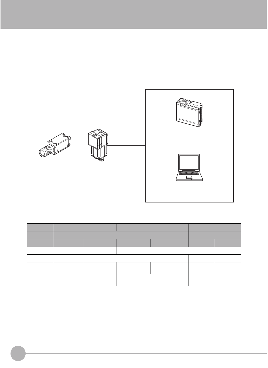
1-1 FQ2-S4-series Vision Sensors
The FQ2-S4 Series features Vision Sensors with integrated cameras and controllers. They can be used to
easily achieve simple inspections and measurements and to easily read and verify IDs.
You can use parallel controls, no-protocol communications on Ethernet, PLC Link communications on Ethernet,
and EtherNet/IP communications on Ethernet as standard features. You can also use a Data Unit to enable
control with full-scale parallel communications or RS-232C communications.
To set up and monitor the Vision Sensor, you can use either the Touch Finder or the PC Tool running on a
computer. For actual operation, you can use the Vision Sensor on a stand-alone basis.
Setup, Image Confirmation, and Logging Tools
Touch Finder
FQ2 Vision Sensor
Used to check images and set the
judgement parameters. It can also be
used to save measurement results and
check status during operation.
PC Tool
Sensor with C-mount
Sensor with
Built-in Lighting
After the Sensor has been set up, it can be
operated alone to perform measurements
without the Touch Finder or PC Tool.
The same functions as those that are
provided by the Touch Finder can be
performed from a computer. The PC Tool
is available free of charge.
FQ2-S4-series Vision Sensors are available in models with 350,000, 760,000, and 1,300,000 pixels. There are
also Sensors with C-mounts that allow you to change the lens, and Sensors with Built-in Lighting. The
differences are given in the following table.
Pixels 350,000 760,000 1,300,000
Ty pe Sensors with Built-in Lighting Sensors with C-mounts
Model FQ2-S4@@@@@ FQ2-S4@@@@@-M FQ2-S4@@@@@-08 FQ2-S4@@@@@-08M FQ2-S4@-13 FQ2-S4@-13M
Partial input Horizontally only Horizontally and vertically
Lens mount --- C-mount
Image processing method
Processing
resolution
Real color Monochrome Real color Monochrome Real color Monochrome
752 × 480 928 × 828 1,280 × 1,024
20
FQ2-S4-series Vision Sensors
FQ2-S4 User’s Manual
Page 23
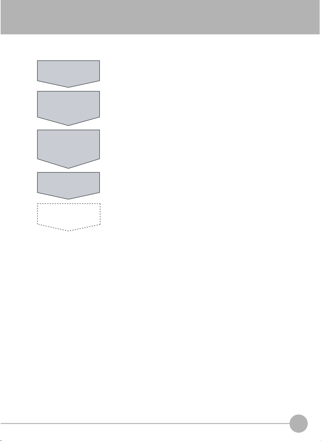
1-2 Measurement Process
This section describes the basic flow of the measurement process.
Trigger input
Take image
Measurement
Output
Logging
• The measurement is started by inputting a trigger signal from an external
device.
• Images are taken according to the trigger.
• The image is measured to see if it matches the configured settings.
• You can also perform calculations based on the measurement results from
inspection items.
• The overall judgement of all inspection items are output using OR logic.
• You can output detailed measurement result from the inspection items.
• Measurement data and image data can be logged in memory in the Sensor or
in an SD card.
1
Introduction
FQ2-S4 User’s Manual
Measurement Process
21
Page 24
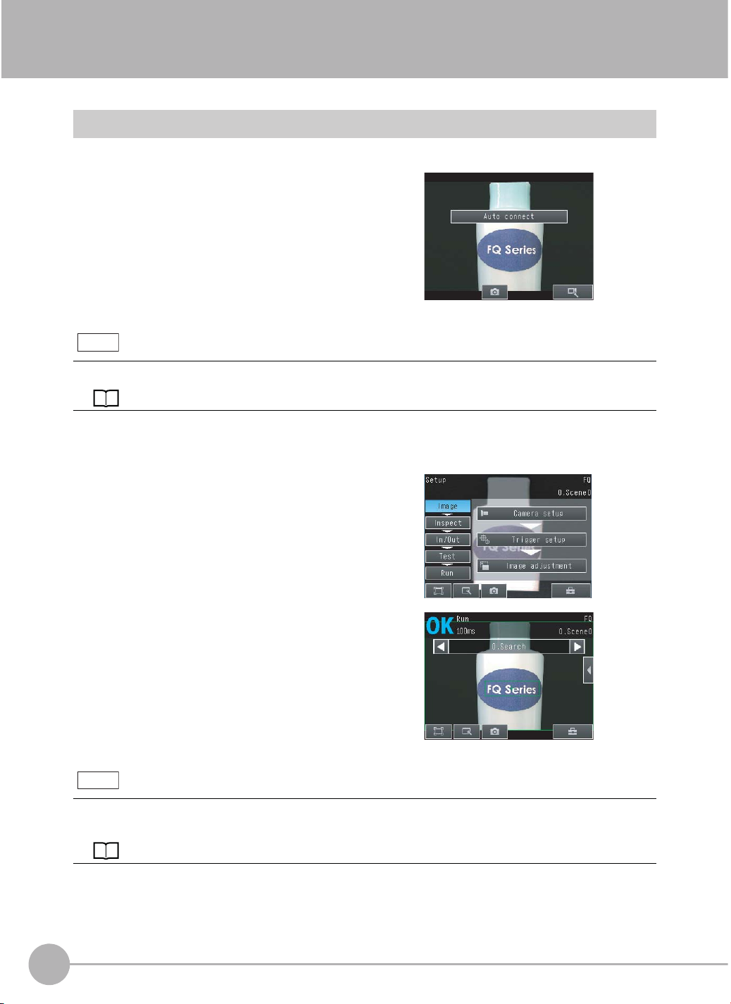
1-3 Startup Display and Display Elements
Startup Display
1 The Sensor is automatically detected by the Touch
Finder when power supply to the Sensor and Touch
Finder is turned ON.
The Auto Connect Display will appear if the Sensor cannot be detected. Check that cables are connected correctly to the Sensor and Touch Finder, and then press
[Auto connect].
Note
If the Sensor is still not detected after pressing [Auto Connect], refer to the following information.
The Sensor cannot be detected: p. 455
2 When the Sensor is detected, the following display will appear.
• The Setup Mode will appear if a Sensor that has not been
set up is connected.
• The Run Mode will appear if a Sensor that has been set
up is connected.
Note
When the Touch Finder is started, IP addresses are automatically set for each Sensor.
To allocate specific IP addresses, set the IP address of each Sensor and the Touch Finder.
Setting Up Ethernet: p. 53
22
Startup Display and Display Elements
FQ2-S4 User’s Manual
Page 25
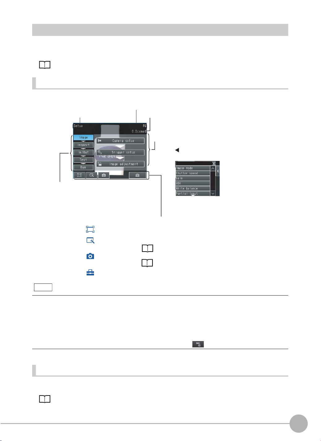
Display Elements
This Sensor has a Setup Mode and a Run Mode.
Refer to the following information for menu items.
p. 458
Setup Mode
In Setup Mode, you can set the image conditions, judgement parameters, and I/O settings for the Sensor.
The name of the mode or the
menu hierarchy is displayed.
The setup flow is shown by these five tabs.
[Image]: Used to adjust the image.
[Inspect]: Used to set the inspection items.
[In/Out]: Used to set the I/O.
[Test]: Used to test and adjust the set measurements.
[Run]: Used to switch to Run Mode.
Only-image Button: Used to select either displaying the camera image and messages, or
Display Button: Used to select the source of the image or to zoom the image.
Capture Button: Used to capture the current screen to the SD card.
Tool Button: Used to call functions, such as saving data or select scenes.
The name of the Sensor being set up is displayed.
The selected scene number is displayed.
The menu changes according to the selected tab page.
• Buttons will appear on the right according to the mode.
• If the [ ] Button appears, pressing it will display the
sub-menu or commands.
This button menu is always displayed.
only the camera image.
Display Functions: p. 244
p. 268
1
Introduction
Note
The Display Button can be used to switch between the following images.
• Camera: The image taken by the camera is displayed.
Live: The live image is displayed.
Freeze: The image that was taken last is displayed.
• Log: A log image saved in internal memory is displayed.
• Logging image file: A log image saved in external memory is displayed.
• Camera image file: An image that was saved in external memory with (Log Image Button) is displayed.
Run Mode
In Run Mode, measurements are performed, and measurement results are output.
p. 223
FQ2-S4 User’s Manual
Startup Display and Display Elements
23
Page 26
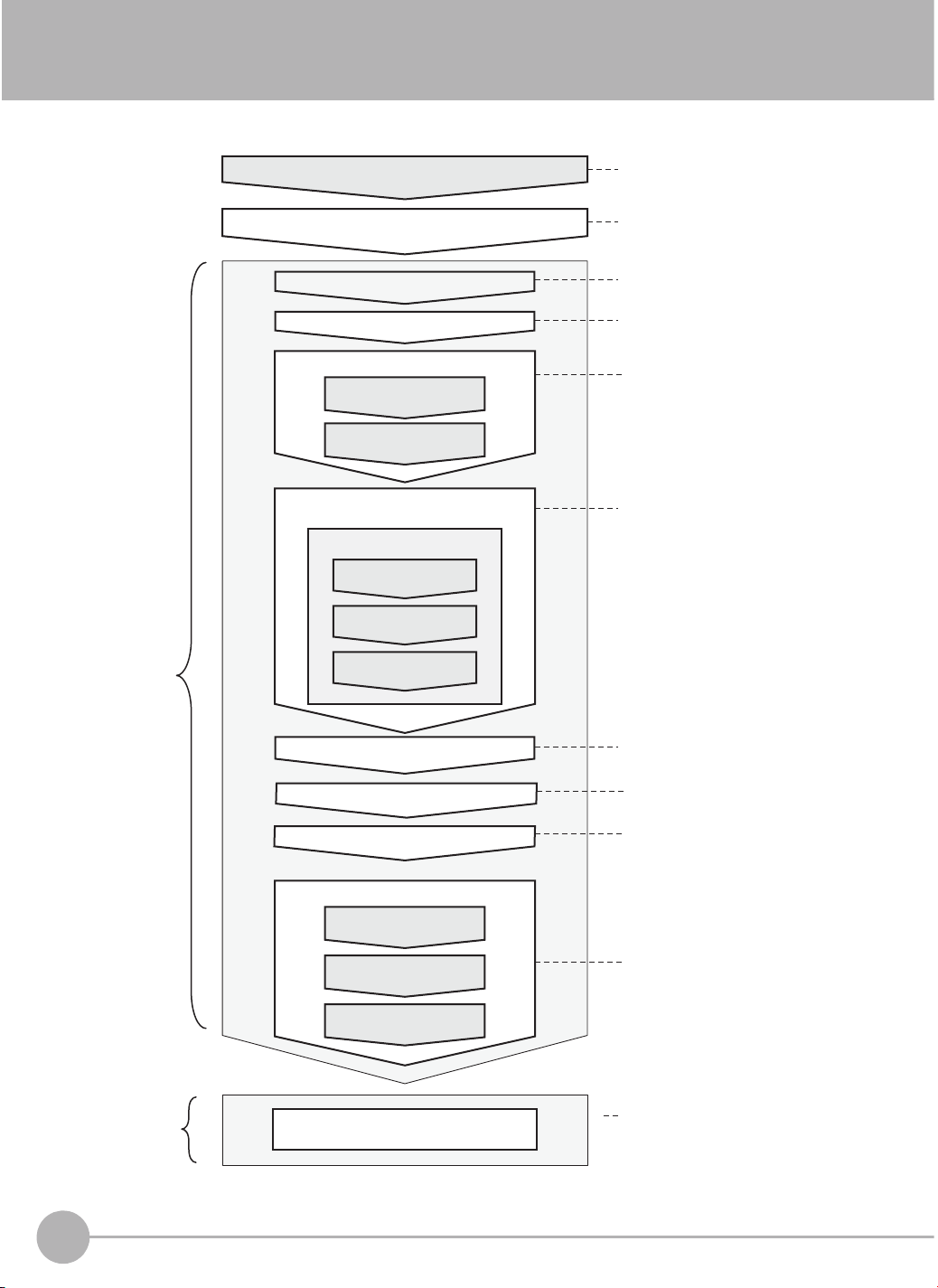
1-4 Basic Operational Flow
The following flow shows the basic operation of FQ2-S4-series Vision Sensors.
Setup
Evaluation
Connections and Wiring
Starting the Sensor
Section 2 Installation and
Connections
Section 1
1-3 Startup Display and Display
Elements
Image Setup ([Image] Tab Page)
Calibration Settings
Image Adjustment
Filtering the images
(filter items)
Compensating for position offset
(position compensation items)
Inspection Setup
([Inspect] Tab Page)
Inspection
Registering
Inspection Items
Teaching
Setting Judgement
*1
Parameters
Section 3 Taking Images
Section 7 Convenient Functions
Section 3
3-5 Adjusting the Images That
Were Taken
Section 4 Setting Up Inspections
Section 4 Setting Up Inspections
Section 7
7-11 Setting the Retry Function
Section 8 Controlling Operation and
Outputting Data with a Parallel
Connection
Section 9 Connecting through
Ethernet
Section 10 Connecting with RS-232C
Section 5 Testing and Saving
Settings
Section 6 Operation
Operation
Calculation Settings ([Inspect] Tab Page)
Retry Details ([Inspect] Tab Page)
Output Settings ([In/Out] Tab Page)
Testing ([Test] Tab Page)
Test Measurement and
Results Verification
Adjusting Judgement
Parameters
Saving the Settings
*2
Starting Operation (Run Mode)
*1: In Setup Mode, the Sensor can be set up and adjusted, but it does not output signals on the I/O lines.
*2: In Run Mode, the Sensor performs measurements and outputs signals on the I/O lines.
24
Basic Operational Flow
FQ2-S4 User’s Manual
Page 27

Installation and Connections
2-1 System Configuration . . . . . . . . . . . . . . . . . . . . . . . . . . . . . . . . . . . . . . 26
2-2 Part Names and Functions . . . . . . . . . . . . . . . . . . . . . . . . . . . . . . . . . . 29
2-3 Installation . . . . . . . . . . . . . . . . . . . . . . . . . . . . . . . . . . . . . . . . . . . . . . . 33
2-4 Wiring . . . . . . . . . . . . . . . . . . . . . . . . . . . . . . . . . . . . . . . . . . . . . . . . . . .42
2-5 Setting Up Ethernet . . . . . . . . . . . . . . . . . . . . . . . . . . . . . . . . . . . . . . . . 53
2
Installation and Connections
Page 28
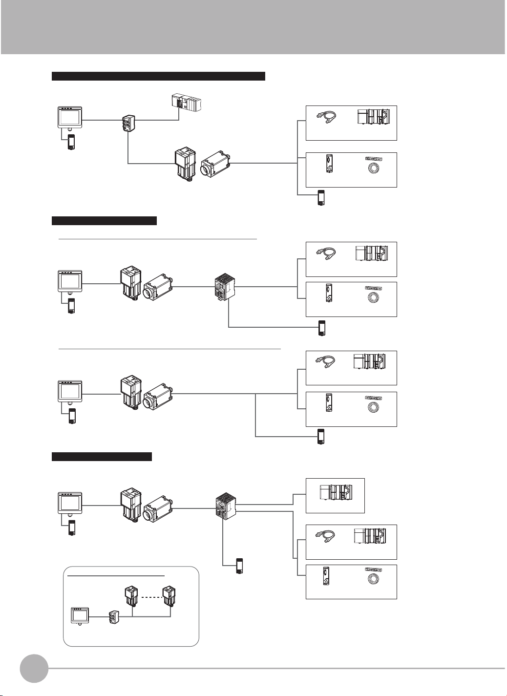
2-1 System Configuration
Ethernet (EtherNet/IP, No-protocol, or PLC Link) Connection
Setup Tool
Touch Finder
or PC Tool
Standard
Ethernet cable
24-V power supply
Industrial EtherNet/IP or
Ethernet Switching Hub
Standard Ethernet cable
Special Ethernet Cable
(RJ45/M12)
Control PLC
FQ2-S4
FQ2-S4@-
@@@@@-@@@
@@@
I/O cable
FL-STC
Lighting Controller
I/O control PLCTrigger sensor
FL-series
External Lighting
Parallel Interface Connection
Connection through a Parallel Interface Sensor Data Unit
Setup Tool
Touch Finder
or PC Tool
24-V power supply
FQ2-S4
FQ2-S4@-
Special
Ethernet Cable
(RJ45/M12)
@@@@@-@@@
@@@
Parallel Interface Sensor Data Unit
Sensor Data
Unit cable
Parallel cable
for FQ-SDU1
Connection with Standard Parallel Interface of the Vision Sensor
Setup Tool
Touch Finder
or PC Tool
Special Ethernet
Cable
(RJ45/M12)
24-V power supply
FQ2-S4
FQ2-S4@-
@@@@@-@@@
@@@
I/O cable
RS-232C Serial Connection
Setup Tool
Touch Finder
or PC Tool
Special Ethernet
Cable (RJ45/M12)
FQ2-S4
FQ2-S4@-
@@@@@-@@@
@@@
RS-232C Interface Sensor Data Unit
RS-232C cable
Sensor Data
Unit cable
Parallel cable
for FQ-SDU2
24-V power supply
Trigger sensor
FL-STC
Lighting Controller
24-V power supply
Trigger sensor
FL-STC
Lighting Controller
24-V power supply
Sensor control PLC
Sensor control PLC
I/O control PLC
FL-series
External Lighting
Sensor control PLC
I/O control PLC
FL-series
External Lighting
24-V power supply
Connecting More Than One Sensors
Setup Tool
Touch Finder
or PC Tool
The Setup Tool can detect up to 32 Sensors and
it can connect to up to eight Sensors at the same time.
26
System Configuration
FQ2 Vision Sensors (8 max.)
Special Ethernet Cable
Switching Hub
(RJ45/M12)
24-V power supply
Trigger sensor
FL-STC
Lighting Controller
Sensor control PLC
I/O control PLC
FL-series
External Lighting
FQ2-S4 User’s Manual
Page 29

Product Model number Remarks
FQ Vision Sensor FQ2-S4@@@@@-@@@
Touch Finder FQ2-D@@ This is a setup console.
PC Tool --- The PC Tool can be used instead of the Touch Finder. If you register as a member,
Parallel Interface
Sensor Data Unit
RS-232C Interface
Sensor Data Unit
FQ Ethernet Cable FQ-WN0@@ Connects the Sensors to external devices such as the Touch Finder, computers, and
Standard RJ45
Ethernet Cable
I/O Cable FQ-WD0@@ Connects the Sensor to the power supply and external devices.
Switching Hub W4S1-0@@ Used to connect multiple Sensors to one Touch Finder or PC Tool.
Sensor Data Unit
cable
Parallel cable for
FQ-SDU1
Parallel cable for
FQ-SDU2
RS-232C cable
(to connect to a
PLC)
FQ2-S4@-@@@
FQ-SDU1@ You can connect a Sensor Data Unit to the I/O cable connector on the Vision Sensor
FQ-SDU2@ You can connect a Sensor Data Unit to the I/O cable connector on the Vision Sensor
--- Connects the Switching Hub to the Touch Finder, computers, and PLCs. Use a con-
*1
FQ-WU0@@ This cable connects the FQ2-S4 Sensor to the Sensor Data Unit.
FQ-VP1@@@ This cable connects the Parallel Interface Sensor Data Unit to an external device.
FQ-VP2@@@ This cable connects the RS-232C Interface Sensor Data Unit to an external device.
Recommended:
XW2Z-200S-V (2 m) or
XW2Z-500S-V (5 m)
This is the Vision Sensor.
you can download the free PC Tool as a special service to purchasers.
Refer to the Member Registration Sheet that is enclosed with the Sensor for the
member registration procedure and the download procedure for special member software.
and connect the Parallel Interface Sensor Data Unit to an external device. This allows
you to output the results of judgement conditions, measurements from inspection
items, and the results of expressions with parallel communications.
and connect the RS-232C Interface Sensor Data Unit to an external device. This
allows you to use no-protocol communications to send and receive commands,
inspection item parameters, and other data between the Sensor and the external
control device that is connected with the RS-232C cable. You can also use the ACK
signal (parallel command normal completion signal) for a parallel output from the
Sensor Data Unit.
PLCs.
nector that complies with the FCC RJ45 standard. (STP (shielded twisted-pair) cable,
category 5e or 6, impedance: 100 Ω)
This cable connects the RS-232C Interface Sensor Data Unit to an external device.
2
Installation and Connections
*1: The shape and dimensions of the Ethernet connector plug and jack are specified in ISO/IEC8877:1992 (JIS X 5110:1996) and RJ-45 of the
FCC regulations. To prevent connector connection failures, the structure of the jack of this product does not allow insertion of plugs that do not
comply with the standard. If a commercially available plug cannot be inserted, it is likely that the plug is non-compliant.
Important
Do not connect network devices other than PLCs on the same network as the Touch Finder or computer. If
another device is connected, the responsiveness of displays and settings of the Touch Finder or computer may
become slow.
FQ2-S4 User’s Manual
System Configuration
27
Page 30

Connection Compatibility
Yes: Supported, No: Not supported
Type of connection to FQ2-S Other connection
EtherNet/IP PLC Link on
EtherNet/IP --- No Yes Yes Yes Yes Yes
PLC Link on Ethernet No --- Yes Yes Yes Yes Yes
TCP no-protocol communications on Ethernet
FINS/TCP no-protocol communications on Ethernet
RS-232C
Parallel
communications
*1: This applies when an RS-232C Interface Sensor Data Unit is connected.
*2: This applies when a Parallel Interface Sensor Data Unit is connected.
*1
Sensor’s standard parallel
communications
Parallel Inter-
*2
face
Yes Yes --- No No Yes Yes
Yes Yes No --- No Yes Yes
Yes Yes No No --- Yes No
Ye s Ye s Ye s Ye s N o -- - N o
Ye s Ye s Ye s Ye s N o N o - - -
Ethernet
TCP no-protocol communications on
Ethernet
FINS/TCP
no-protocol
communications on
Ethernet
RS-232C *1Parallel communications
Sensor’s
standard parallel communications
Note
Parallel Inter-
*2
face
Connections Across Network Routers
You can connect to a Sensor on a different network than the Touch Finder or PC Tool through a router.
• To connect to a Sensor, directly specify the IP address of the Sensor. Automatic connection to a Sensor is not
possible.
• Use a fixed IP address for the Sensor to connect to.
28
System Configuration
FQ2-S4 User’s Manual
Page 31

2-2 Part Names and Functions
FQ2-S4@@@@@-@@@ (Sensors with Built-in Lighting)
(6)
(7)
No. Name Description
(1) Lighting LEDs for illumination
(2) Camera lens This lens can be focused.
(3) I/O Cable connector An FQ-WD or FQ-WU I/O Cable is used to connect the Sensor to the power
supply and external I/O.
(4) Ethernet cable connector An FQ-WN Ethernet Cable is used to connect the Sensor to external
devices such as PLCs, the Touch Finder, or computers.
(5) Focus adjustment screw Used to adjust the focus of the image.
(6) Operation
indicators
(7) Mounting Bracket Used to mount the Sensor.
OR Lights orange when the overall judgement output (OR) signal turns ON.
ETN Lights orange during Ethernet communications.
ERROR Lights red when an error occurs.
11-1 Error Histories p. 452
BUSY Lights green when the Sensor is executing a process.
* You can change the BUSY indicator to a RUN indicator.
This indicator is set by default to a BUSY indicator, but if you change it to a
RUN indicator, it will light green during operation.
Changing the Sensor’s BUSY Indicator: p. 278
The Mounting Bracket can be attached to the front, left side, right side, or
back of the Sensor.
(5)
(1)
(2)
(4)
(3)
2
Installation and Connections
FQ2-S4 User’s Manual
Part Names and Functions
29
Page 32

FQ2-S4@-@@@ (Sensors with C-mounts)
(5)
(4)
(1)
(7)
(5)
(5)
Bottom
(8)
(3)
(2)
(5)
(6)
Sensor Mounted to Base
No. Name Description
(1) C-mount lens mounting surface The C-mount lens and macro ring are attached here. Determine the appro-
priate CCTV lens (C-mount lens) to use based on the field of view required
for the size of the measurement object.
Optical Diagrams: p. 35
(2) I/O Cable connector An FQ-WD or FQ-WU I/O Cable is used to connect the Sensor to the power
supply, external I/O, and Data Unit.
(3) Ethernet Cable connector An FQ-WN Ethernet Cable is used to connect the Sensor to external
devices such as the Touch Finder or computers.
(4) Operation
indicators
(5) Mounting holes These mounting holes for M3 screws are used to mount the Camera and to
(6) Mounting base (enclosed) The mounting base has 1/4-20UNC threads and is used to mount the Sen-
(7) C-mount cover This cover is attached to the C-mount lens fitting when a lens is not
(8) Connector cover This cover is attached to the connection when an Ethernet Cable is not con-
OR Lights orange when the overall judgement output (OR) signal turns ON.
ETN Lights orange during Ethernet communications.
ERROR
BUSY Lights green when the Sensor is executing a process.
Lights red when an error occurs.
11-1 Error Histories p. 452
* You can change the BUSY indicator to a RUN indicator.
This indicator is set by default to a BUSY indicator, but if you change it to a
RUN indicator, it will light green during operation.
Changing the Sensor’s BUSY Indicator: p. 278
mount to the base. There are mounting holes on the top, bottom, left, and
right surfaces.
Dimensions: p. 555
sor. The base can be attached to the bottom, top, left, or right side of the
Sensor.
* We recommend mounting the Sensor with the mounting screw holes. The
mounting base does not necessarily need to be used.
attached.
nected.
30
Part Names and Functions
FQ2-S4 User’s Manual
Page 33

Touch Finder
(1)
(6) (7)
(3)
(4)
(5)
(2)
(12)
(10)
(11)
(8)
(9)
No. Name Description
(1) Operation
indicators
(2) LCD/touch panel Displays the setting menu, measurement results, and images input by the
(3) SD card slot An SD card can be inserted.
(4) Battery cover
(5) Power supply switch Used to turn the Touch Finder ON and OFF.
(6) Touch pen holder The touch pen can be stored here when it is not being used.
(7) Touch pen Used to operate the touch panel.
(8) DC power supply connector Used to connect a DC power supply.
(9) Slider Used to mount the Touch Finder to a DIN Track.
(10) Ethernet port Used when connecting the Touch Finder to the Sensor with an Ethernet
(11) Strap holder This is a holder for attaching the strap.
(12) AC power supply connector
*1: Applicable to the FQ2-D31 only.
POWER Lights green when the Touch Finder is turned ON.
ERROR Lights red when an error occurs.
11-1 Error Histories p. 452
SD ACCESS Lights yellow when an SD card is inserted.
Flashes yellow when the SD card is being accessed.
CHARGE
*1
*1
Lights orange when the Battery is charging.
camera.
The Battery is inserted behind this cover.
Remove the cover when mounting or removing the Battery.
p. 50
cable. Insert the connector until it locks in place.
*1
Used to connect the AC adapter.
2
Installation and Connections
FQ2-S4 User’s Manual
Part Names and Functions
31
Page 34

Sensor Data Units
(1)
(4)
(5)
(8)
(2)
Front Surface of Parallel Interface
Sensor Data Unit
(3) (6)
Back Surface of Parallel Interface
Sensor Data Unit
No. Name Description
(1) Sensor connector Connects to the FQ2-S4.
(2) Power supply and ground termi-
nal block
(3) Parallel I/O connector Connects to the I/O connector.
(4) I/O indicators POWER/
ERROR
RUN Lights green during operation.
BUSY Lights yellow when the Sensor is executing a process.
SENSOR Lights yellow when the Sensor is connected.
OR-OK Lights green when the overall judgement result is OK.
OR-NG Lights red when the overall judgement result is OFF or an error occurs.
232C_COM Lights yellow during RS-232C communications. (Provided only on the FQ-
(5) DIN Track mounting section Mounts the Data Unit to a DIN Track.
(6) Slider Used to secure the Data Unit to a DIN Track.
(7) RS-232C connector Connects to the RS-232C connector.
(8) Parallel I/O connector Connects to the I/O connector.
Connects to the 24-V power source and the ground line.
Lights green when power is being supplied.
Lights red when an error occurs.
SDU2@.)
(4)
(7)
RS-232C Interface
Sensor Data Unit
32
Part Names and Functions
FQ2-S4 User’s Manual
Page 35

2-3 Installation
Installing the Sensor
FQ2-S4@@@@@ (Sensors with Built-in Lighting)
Installation Procedure
2
1 Align the tabs on one side of the Mounting Bracket with
the slot on the Sensor.
The FQ-XL Mounting Bracket can be attached to the back,
side, or front of the Sensor.
2 Press the Mounting Bracket onto the Sensor until the oth-
er tabs click into place.
3 Use the following optical charts to check the field of view
and installation distance of the Sensor so that it is mounted at the correct position.
Tightening torque (M4): 1.2 N·m
Horizontal field of view
Vertical field
of view
Installation distance (L)
FQ2-S4@010F
Installation distance (L) (mm)
55
The optical chart indicates the horizontal
field of view. The vertical field of view
depends on the model as follows:
FQ2-S4@@@@@:
Approx. 60% of the horizontal field of view
FQ2-S4@@@@@-08@:
Approx. 90% of the horizontal field of view
Note: The tolerance is ±10%.
FQ2-S4@100F
Installation distance (L) (mm)
1,000
Installation and Connections
Mounting
Bracket
45
35
6
FQ2-S4@050F
Installation distance (L) (mm)
210
130
50
0
FQ2-S4 User’s Manual
8
Horizontal field of view (mm)
20
Horizontal field of view (mm)
10
40
12
14
60
600
200
0100
Horizontal field of view (mm)
FQ2-S4@100N
Installation distance (L) (mm)
400
0
0
200 400
Horizontal field of view (mm)
200
300
Installation
33
Page 36

Important
• There is a certain amount of deviation among Sensors in the center of the optical axis. For this reason, when installing the Sensor, check the center of the image and the field of view on the LCD monitor of the Touch Finder and in
the PC Tool.
Removal Procedure
1 Insert a flat-blade screwdriver between the Mounting Brack-
et and the Sensor case on either side and remove the
Mounting Bracket.
Mounting
Bracket
FQ2-S4@-@@@ (Sensors with C-mounts)
Installation Procedure
Directly Mounting the Sensor
1 Mount the Sensor with M3 screws.
Tightening torque: 0.54 N·m
Effective depth of mounting holes: 4 mm
Important
Refer to the dimension drawings in the appendix for the positions of
the screw holes.
Mounting the Sensor to the Base
1 You can attach the mounting base to the bottom, top, left,
or right surface.
(Recommended mounting screw tightening torque:
0.54 N·m)
Tightening torque: 0.54 N·m
Effective depth of mounting holes: 4 mm
2 Mount the Sensor with M3 screws.
Tightening torque: 0.54 N·m
Effective depth of mounting holes: 4 mm
34
Installation
FQ2-S4 User’s Manual
Page 37

Lens Selection
Use the following optical diagrams to determine the Lens, camera installation distance, and detection range.
Optical Diagrams
The following values are estimates only. Adjustment is required after installing the camera.
3Z4S-LE SV-@@@@H High-resolution, Low-distortion Lenses
3Z4S-LE
10000
1000
100
Camera installation distance (mm)
10
t20
t25
t30
t40
t50
t40
t50
t50
t30
t40
t25
t30
t15
t20
t25
t10
t30
t15
t20
t25
t10
t15
t20
t5
t10
t5
t2
Y axis of field of view (mm)
t0
t0
t0
t5
t10
t15
t5
t10
t5
t15
t5
t2
t1
t2
t0.5
t1
t0.5
t0
t0
t0
t0
t0
t0
1000100101
SV-0614H
SV-0814H
SV-1214H
SV-1614H
SV-2514H
SV-3514H
SV-5014H
SV-7525H
SV-10028H
t: Macro ring
Examples
t0: Macro ring is
not required.
t5: A 5-mm macro
ring is required.
2
Installation and Connections
3Z4S-LE SV-@@@@V-series Lenses
10000
t30
t40
1000
100
Camera installation distance (mm)
t30
t50
t40
t50
t25
t40
t30
t15
t20
t25
t25
t15
t10
10
1
FQ2-S4 User’s Manual
t5
t10
t5
t15
t20
t10
t15
t25
t20
t25
t10
t15
t20
t5
t10
t10
t5
t5
t2
t5
t2
t1
t2
t1
t2
t1
t5
t2
t1
t0.5
t1
t0.5
t0.5
Y axis of field of view (mm)
3Z4S-LE
t0
t0
t1
t0.5
t0
t0
t0
t0
t0
t0
t0
SV-0614V
SV-0813V
SV-1214V
SV-1614V
SV-2514V
SV-3518V
SV-5018V
SV-7527V
SV-10035V
t: Macro ring
Examples
t0: Macro ring is
not required.
t5: A 5-mm macro
ring is required.
100010010
Installation
35
Page 38

The X axis in the above optical diagrams represent field of view (mm)*1. The Y axis represents the camera
installation distance (mm) or WD (mm). These optical diagrams show the relationship between the detection
range and installation distance for different CCTV Lenses. The values vary for each Lens. Pay close attention
to the Lens that you are using when you refer to these optical diagrams. The macro ring thickness to be used is
given as, for example “t5.0,” on the graphs. “t0” means that a macro ring is not required. “t5.0” means that you
must use a 5-mm macro ring.
Y
Field of view
X
*1: The Y axis in the optical charts represents the height of the field of view.
Example: If you use an 3Z4S-LE SV-2514H Lens for a measurement object that requires field of view of 35
mm, the camera installation distance must be 200 mm and a 2-mm macro ring is required.
Camera
Macro ring t@ (mm)
Camera lens
Camera installation distance (mm)
Measurement object
Lens Models and Dimensions
Filter threads
Total length
Field of view (mm)
Maximum outside
1-32 UNF
(C-mount threads)
diameter
36
Installation
FQ2-S4 User’s Manual
Page 39

3Z4S-LE SV-@@@@H High-resolution, Low-distortion Lenses
Lens model Focal length Brightness Maximum
Total length Filter size
outside diameter
3Z4S-LE SV-0614H 6.1 mm F1.4 42 mm 57.5 mm M40.5 P0.5
3Z4S-LE SV-0814H 8.0 mm F1.4 39 mm 52.5 mm M35.5 P0.5
3Z4S-LE SV-1214H 12.3 mm F1.4 30 mm 51.0 mm M27 P0.5
3Z4S-LE SV-1614H 16.2 mm F1.4 30 mm 47.5 mm M27 P0.5
3Z4S-LE SV-2514H 25.0 mm F1.4 30 mm 36.0 mm M27 P0.5
3Z4S-LE SV-3514H 35.01 mm F1.4 44 mm 45.5 mm M35.5 P0.5
3Z4S-LE SV-5014H 50.0 mm F1.4 44 mm 57.5 mm M40.5 P0.5
3Z4S-LE SV-7525H 75 mm F2.5 36 mm 49.5 mm M34.0 P0.5
3Z4S-LE SV-10028H 100 mm F2.8 39 mm 66.5 mm M37.5 P0.5
3Z4S-LE SV-@@@@V-series Lenses
Lens model Focal length Brightness Maximum out-
Total length Filter size
side diameter
3Z4S-LE SV-0614V
3Z4S-LE SV-0813V
3Z4S-LE SV-1214V
3Z4S-LE SV-1614V
3Z4S-LE SV-2514V
3Z4S-LE SV-3518V
3Z4S-LE SV-5018V
3Z4S-LE SV-7527V
3Z4S-LE SV-10035V
6.20 mm F1.4 29 mm 30.0 mm M27 P0.5
8.05 mm F1.3 28 mm 34.0 mm M25.5 P0.5
12.43 mm F1.4 29 mm 29.5 mm M27 P0.5
16.34 mm F1.4 29 mm 24.0 mm M27 P0.5
25.17 mm F1.4 29 mm 24.5 mm M27 P0.5
34.75 mm F1.8 29 mm 33.5 mm M27 P0.5
47.97 mm F1.8 32 mm 37.0 mm M30.5 P0.5
76.71 mm F2.7 32 mm 42.0 mm M30.5 P0.5
95.4 mm F3.5 32 mm 43.9 mm M30.5 P0.5
2
Installation and Connections
FQ2-S4 User’s Manual
Installation
37
Page 40

Macro Rings
Macro rings are inserted between the Lens and the camera to adjust the focus. You can use up to seven macro
rings to achieve the required thickness.
Macro ring
Model Maximum out-
Thickness
side diameter
3Z4S-LE SV-EXR 31 mm 7-piece set
Thickness:
0.5 mm
10mm
Important
• Do not stack 0.5 mm, 1.0 mm, and 2.0 mm macro rings. These sizes fit between the Lens and the threaded portion
of other macro rings. If two or more are stacked together, the screw cannot be tightened securely.
• The macro rings may need to be reinforced depending on the vibration conditions if over 30 mm is used.
20mm
40 mm20 mm10 mm5 mm1 mm 2 mm
40mm
Installing the Touch Finder
Installation Precautions
Install the Touch Finder in the following orientation to allow sufficient heat dissipation.
Do not mount it in the following orientations.
Important
• To improve ventilation, leave space on both sides of the Touch Finder. The distance between the Touch Finder and
other devices should be at least that shown in the following diagram.
15 mm min.
• Make sure that the ambient temperature is 50°C or lower. If it exceeds 50°C, install an cooling fan or an air conditioner and maintain the temperature at 50°C or lower.
• To prevent interference by noise, do not mount the Sensor on panels which contain high-voltage devices.
• To keep the level of noise from the surrounding environment to a minimum, install the Sensor and Touch Finder at
least 10 m away from power lines.
38
Installation
15 mm min.
FQ2-S4 User’s Manual
Page 41
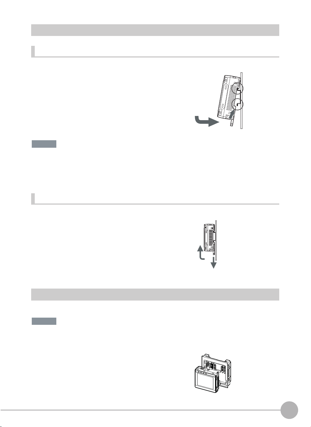
Mounting to DIN Track
Installation Procedure
1 Press the slider on the Touch Finder to the top.
2 Hook the clip at the top of the Touch Finder on to the DIN
Track.
3 Press the Touch Finder onto the DIN Track until the bottom
clip clicks into place.
3
Important
• Attach End Plates (sold separately) on the sides of the Touch Finder on the DIN Track.
• If other devices will be installed next to the Touch Finder on the same DIN Track, make sure that sufficient space is
kept between the devices as indicated on previous page.
• Always hook the clip at the top of the Touch Finder on the DIN Track first. If the lower clip is hooked on first, the
Touch Finder will not be mounted very securely.
Removal Procedure
2
3
1
1 Pull down on the slider on the Touch Finder.
2 Lift the Touch Finder at the bottom and remove it from the
DIN Track.
2
1
2
Installation and Connections
Mounting to a Control Panel
The Touch Finder can be mounted on a panel using the FQ-XPM Panel Mounting Adapter.
Important
• Always turn OFF the Touch Finder power before attaching or detaching the Panel Mount Adapter. Attaching or
detaching with the power turned ON may cause a failure.
1 Set the Touch Finder in the Panel Mount Adapter.
FQ2-S4 User’s Manual
Installation
39
Page 42

2 Press the slider up on the Touch Finder.
3 Create holes in the panel for mounting.
Refer to the following page for hole dimensions.
p. 560
4 Connect the cable to the Touch Finder.
5 Mount the Touch Finder with the Panel Mount Adapter from
the front of the panel.
6 Hook the hooks on the Mounting Bracket in the four holes
of the Panel Mount Adapter and secure them with screws.
(Tightening torque: 1.2 N·m)
7 Check that the Touch Finder is attached properly to the
Panel.
Mounting
Bracket
Using the Touch Finder as a Portable Device (with Battery)
The Touch Finder with a Battery can be used as a portable device. Use the strap when carrying it to prevent
dropping it.
There are two types of straps (FQ-XH, sold separately), a Neck Strap and a Hand Strap.
Neck Strap
Hand Strap
1 Attach the Mini-strap to the Touch Finder.
There are a total of four holes for attaching the Mini-strap on the left and on the right of the Touch Finder.
40
Installation
FQ2-S4 User’s Manual
Page 43

2 Connect the Neck Strap or Hand Strap to the Mini-strap.
Mini-strap
Neck Strap or Hand
Strap
Mounting Sensor Data Units
Mounting to DIN Track
Installation Procedure
1 Lock the sliders at the top and bottom of the Sensor Data
Unit.
2 Press the slider on the Sensor Data Unit to the top.
3 Hook the clip at the top of the Sensor Data Unit on to the DIN
Track.
4 Press the Sensor Data Unit onto the DIN Track until the bot-
tom clip clicks into place.
Important
2
Installation and Connections
2
3
1
3
• Attach End Plates (sold separately) on the sides of the Sensor Data Unit on the DIN Track.
• Always hook the clip at the top of the Sensor Data Unit on the DIN Track first. If the lower clip is hooked on first, the
Touch Finder will not be mounted very securely.
Removal Procedure
1 Pull down on the slider on the Sensor Data Unit.
2 Lift the Sensor Data Unit at the bottom and remove it from
the DIN Track.
2
FQ2-S4 User’s Manual
1
Installation
41
Page 44
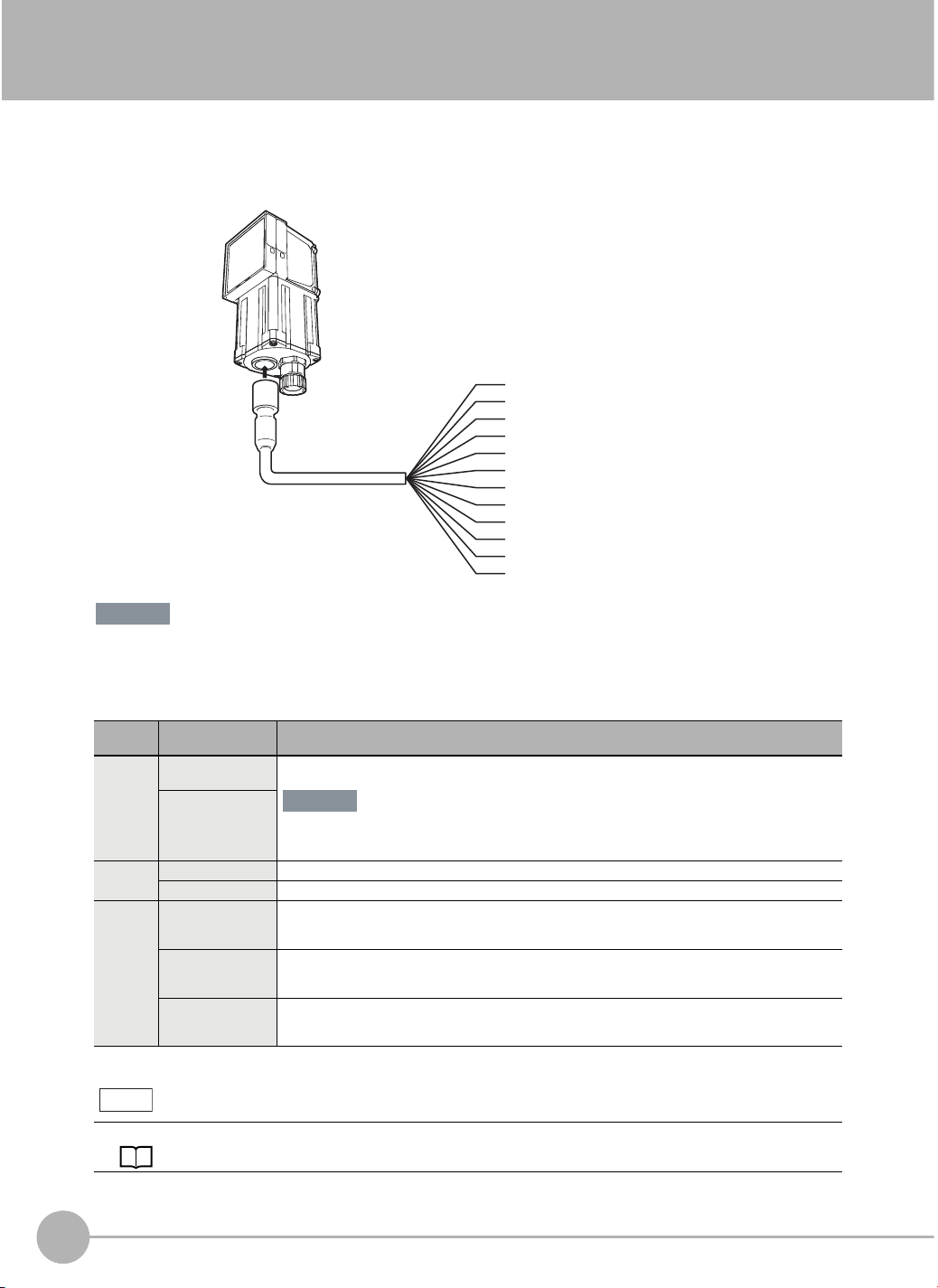
2-4 Wiring
Wiring the Sensor
Connect the I/O Cable to the I/O Cable connector located at the bottom of the Sensor.
FQ2-S4
@@@@@
(Sensors with Built-in Lighting
or Sensors with C-mounts)
FQ-WD0@@
I/O Cable
Brown
Blue
Black
Orange
Light blue
Pink
Gray
Green
Red
White
Purple
Yellow
Power supply
GND
OUT0 (OR)
OUT1 (BUSY)
OUT2 (ERROR)
TRIG
IN0
IN1
IN2
IN3
IN4
IN5
Important
• Cut off lines that are not required so that they do not come into contact the other signal lines.
• Do not allow the load current to exceed 50 mA. The output circuit may be damaged if the load current exceeds 50
mA.
Classification
Powe r
supply
Inputs TRIG This terminal is the trigger signal input.
Outputs OUT0 (OR) By default, this is the OR output signal (overall judgement).
Signal Application
Power supply
(24 V)
GND
IN0 to IN5 These are the command input terminals.
OUT1 (BUSY) By default, this is the BUSY output signal.
OUT2 (ERROR) By default, this is the ERROR output signal.
These terminals are for the external power supply (24 V).
Important
Wire the power supply separately from other devices. If the wiring for other devices is placed
together or in the same duct as the wiring for the Vision Sensor, the influences of electromagnetic
induction may cause the Sensor to malfunction or may damage it.
The assignment can be changed to RUN, READY, an individual judgement signal from OR0 to
OR31, the STGOUT (strobe trigger output), or an expression judgement from 0 to 31.
The assignment can be changed to RUN, READY, an individual judgement signal from OR0 to
OR31, the STGOUT (strobe trigger output), or an expression judgement from 0 to 31.
The assignment can be changed to RUN, READY, an individual judgement signal from OR0 to
OR31, the STGOUT (strobe trigger output), or an expression judgement from 0 to 31.
Note
The assignments of I/O signals can be changed.
Section 8 Controlling Operation and Outputting Data with a Parallel Connection: p. 279
42
Wiring
FQ2-S4 User’s Manual
Page 45

I/O Signal Circuit Diagrams
PNPNPN
Power supply (24 VDC)
Brown
Load
24 VDC
Internal circuits
Internal circuits
Black
OUT0 (OR)
Orange
OUT1 (BUSY)
Light blue Red
Blue
Pink
Gray
Green
Red
White
Purple
Yellow
OUT2 (ERROR)
GND (0V)
TRIG
IN0
IN1
IN2
IN3
IN4
IN5
Important
Preventing Chattering
• The Sensor is equipped with an anti-chattering function, but if the chattering is 100 μs or longer, a faulty input may
occur. (Input signals of 99 μs or shorter are ignored. Signals of 100 μs or longer are treated as input signals.)
• Use no-contact output devices (e.g., SSR or PLC transistor output) for the input signals. If contacts (e.g., relay) are
used, chattering may cause the trigger to be input again during execution of a measurement.
Power supply (24 VDC)
Brown
Pink
TRIG
IN0
Gray
Green
IN1
IN2
IN3
White
Purple
IN4
Yellow
IN5
Light blue
Orange
Black
Blue
OUT2 (ERROR)
OUT1 (BUSY)
OUT0 (OR)
GND (0V)
24 VDC
Load
2
Installation and Connections
Power Supply Specifications When a Switching Regulator Is Connected
Use a power supply that meets the following specifications. (The power supply is sold separately.)
Item Description
FQ2-S4@@@@@ FQ2-S4@-@@@
Power supply voltage 24 VDC (21.6 to 26.4 V)
Recommended Power Supply S8VS-06024@ (24 VDC, 2.5 A) S8VS-01524@ (24 VDC, 0.65 A)
External power supply terminal screws M4 (tightening torque: 1.2 N·m)
Important
Supply power from a DC power supply for which measures have been applied to prevent high voltages (e.g., a safety
extra low voltage circuit).
If UL certification is required for the overall system, use a UL Class II DC power supply.
Attaching the LED Warning Label
Attach the enclosed LED warning label to the cable or other location. The LED warning label must be attached
to a location that is readily visible from the Sensor.
Attachment Example
Warning Label
Warning Label
12-6 LED Safety: p. 575
FQ2-S4 User’s Manual
Wiring
43
Page 46

Wiring Sensor Data Units
Parallel Interface Sensor Data Unit (FQ-SDU1@)
FQ2-S4 (Sensors with Built-in Lighting or
Sensors with C-mounts)
FQ-WU0@@
Sensor Data Unit Cable
(Screw size: M3,
Tightening torque:
0.54 N·m)
Power supply (24 V)
Power supply (0 V)
Frame ground
123132
343334
563536
783738
9103940
11 12 41 42
13 14 43 44
15 16 45 46
17 18 47 48
19 20 49 50
21 22 51 52
23 24 53 54
25 26 55 56
27 28 57 58
29 30 59 60
For the I/O connector harness, use an FQ-VP1@@@ Parallel Cable for the FQ-SDU1 or a MIL-standard
harness, such as the OMRON XZ2F. (The Cables are sold separately.)
Signal Application
Power supply (24 V)
These terminals are for the external power supply (24 V).
Power supply (0 V)
Important
• Wire the power supply separately from other devices. If the wiring for other devices is
placed together or in the same duct as the wiring for the Vision Sensor, the influence
of electromagnetic induction may cause the Sensor to malfunction or may damage it.
• Do not allow the load current to exceed 50 mA. The output circuit may be damaged if
the load current exceeds 50 mA.
This is the frame ground terminal. Connect it to the ground wire.
FQ2-S4 User’s Manual
44
Frame ground
Wiring
Page 47

FQ-SDU10/SDU15 Terminal Signal Names
Pin Signal IN/
1 COMOUT1 - Output signal common (DO0 to
2NC
*1
Function Pin Signal IN/
OUT
DO15)
31 COMIN0 - Input signal common (all inputs
Function
OUT
except TRIG)
- 32 COMIN1 - Input signal common (TRIG)
3 D0 OUT Data output 33 TRIG IN Measurement trigger input
4 D1 OUT Data output 34 NC
5 D2 OUT Data output 35 NC
*1
*1
-
6 D3 OUT Data output 36 RESET IN Reset input
7 D4 OUT Data output 37 IN0 IN Command input
8 D5 OUT Data output 38 IN1 IN Command input
9 D6 OUT Data output 39 IN2 IN Command input
10 D7 OUT Data output 40 IN3 IN Command input
11 D8 OUT Data output 41 IN4 IN Command input
12 D9 OUT Data output 42 IN5 IN Command input
13 D10 OUT Data output 43 IN6 IN Command input
14 D11 OUT Data output 44 IN7 IN Command input
15 D12 OUT Data output 45 NC
16 D13 OUT Data output 46 NC
*1
*1
-
17 D14 OUT Data output 47 DSA IN Data send request signal
18 D15 OUT Data output 48 NC
19 NC
20 NC
21 NC
22 NC
23 NC
24 NC
25 NC
26 NC
27 NC
28 NC
29 NC
30 NC
*1: Leave all signal terminals that are labeled “NC” open.
*2: You can select whether to turn the external lighting ON (Positive) or OFF (Negative) when the signal turns ON. (The setting is called the
*1
*1
*1
*1
*1
*1
*1
*1
*1
*1
*1
*1
strobe output polarity.)
-49NC
-50NC
-51NC
- 52 ACK OUT Command execution completed
- 53 RUN OUT ON during measurement mode
- 54 BUSY OUT ON during process execution
- 55 OR OUT Overall judgement result
- 56 ERROR OUT ON during error
- 57 STGOUT OUT Strobe trigger output
- 58 SHTOUT OUT Shutter trigger output
- 59 GATE OUT ON during the set output time.
- 60 COMOUT0 - Output signal common (ACK,
*1
*1
*1
*1
-
-
-
-
flag
*2, *3
*4
RUN, BUSY, OR, ERROR,
STGOUT, SHTOUT, and GATE)
Changing the Output Timing and Output Time of the STGOUT Signal: p. 316
*3: This control signal is used to turn ON external lighting when an image is taken. Connect this signal to external lighting.
*4: This signal is output to an external device when exposure of the imaging elements is completed. If you want to move the Sensor to the next
measurement location after a measurement is completed, move the Sensor only after this signal turns ON.
Shutter Output Signal (SHTOUT)
Trigger input (TRIG)
Imaging element
shutter signal
SHTOUT
The SHTOUT signal turns ON for approximately 10 ms (fixed) when the shutter time (exposure period) elapses after
the trigger is input from an external device.
ON
OFF
ON
OFF
ON
OFF
Trigger delay
Shutter time
10 ms
2
Installation and Connections
FQ2-S4 User’s Manual
Wiring
45
Page 48

RS-232C Interface Sensor Data Unit (FQ-SDU2@)
FQ2-S4 (Sensors with Built-in Lighting or
Sensors with C-mounts)
FQ-WU0@@
Sensor Data Unit Cable
1 2 17 18
3 4 19 20
5 6 21 22
7 8 23 24
9 102526
11 12 27 28
13 14 29 30
15 16 31 32
(Screw size: M3,
Tightening torque:
0.54 N·m)
Power supply (24 V)
Power supply (0 V)
Frame ground
RS-232C connector
For the I/O connector harness, use an FQ-VP2@@@ Parallel Cable for the FQ-SDU2 or a MIL-standard
harness, such as the OMRON XZ2F. (The Cables are sold separately.)
Signal Application
Power supply (24 V)
These terminals are for the external power supply (24 V).
Power supply (0 V)
Important
• Wire the power supply separately from other devices. If the wiring for other devices is
placed together or in the same duct as the wiring for the Vision Sensor, the influence
of electromagnetic induction may cause the Sensor to malfunction or may damage it.
• Do not allow the load current to exceed 50 mA. The output circuit may be damaged if
the load current exceeds 50 mA.
Frame ground
This is the frame ground terminal. Connect it to the ground wire.
46
Wiring
FQ2-S4 User’s Manual
Page 49

FQ-SDU20/SDU25 Parallel Pin Signal Names
Pin Signal IN/
1 IN0 IN Command input 17 COMIN0 - Input signal common (RESET
2 IN1 IN Command input
3 IN2 IN Command input 18 COMIN1 - Input signal common (TRIG)
4 IN3 IN Command input 19 TRIG IN Measurement trigger input
5 IN4 IN Command input 20 NC
6 IN5 IN Command input 21 NC
7NC
8NC
9NC
10 NC
11 NC
12 NC
13 NC
14 NC
15 NC
16 NC
*1
*1
*1
*1
*1
*1
*1
*1
*1
*1
Function Pin Signal IN/
OUT
*1
*1
- 22 RESET IN Reset input
-23NC
- 24 ACK OUT Command execution completed
- 25 RUN OUT ON during measurement mode
- 26 BUSY OUT ON during process execution
- 27 OR OUT Overall judgement result
- 28 ERROR OUT ON during error
- 29 STGOUT OUT Strobe trigger output
- 30 SHTOUT OUT Shutter trigger output
-31NC
32 COMOUT0 - Output signal common (ACK,
*1
*1
Function
OUT
and IN0 to IN5)
-
-
-
flag
-
RUN, BUSY, OR, ERROR,
STGOUT, and SHTOUT)
*1: Leave all signal terminals that are labeled “NC” open.
FQ-SDU20/SDU25 RS-232C Pin Signal Names
2
Installation and Connections
RS-232C Connector
Pin No. Signal name Function
1 NC Not connected
5
4
3
2
1
9
8
7
6
Pin numbers will depend on the external device being connected. Refer to the manual for the personal
computer or PLC being connected.
Use a compatible connector.
• Recommended items
Manufacturer Model
Socket OMRON Corporation XM3D-0921
Hood OMRON Corporation XM2S-0913
2 RD For RS-232C
3 SD For RS-232C
4 NC Not connected
5 GND Signal ground
6 NC Not connected
7 NC Not connected
8 NC Not connected
9 NC Not connected
FQ2-S4 User’s Manual
Wiring
47
Page 50

Wiring
The maximum cable length is 15m.
• RS-232C
Controller
Signal name
RD
SD
GND
Pin No.
2
3
5
Use a shielded cable.
External device to be connected
Pin No.
*
*
*
RS/CS control cannot be used.
Signal name
RD
SD
GND
Connection Method
Align the connector with the socket and press it straight into place, then fix it with the screws on both sides of
the connector.
Important
Turn OFF the power supply before connecting or disconnecting a Cable. Peripheral devices may be damaged if the
cable is connected or disconnected with the power ON.
48
Wiring
FQ2-S4 User’s Manual
Page 51

I/O Signal Circuit Diagrams
NPN
Input Circuit
Input terminal
+
COM_I
3 KΩ
1000 pF
910 Ω
Internal circuits
Output Circuit
Internal
circuits
Output terminal
L
Load
COM_O
+
PNP
Input Circuit
Input terminal
+
COM_I
3 KΩ
1000 pF
910 Ω
Internal circuits
Output Circuit
Internal
circuits
COM_O
+
Load
L
Output terminal
Important
Preventing Chattering
• The Sensor is equipped with an anti-chattering function, but if the chattering is 100 μs or longer, a faulty input may
occur. (Input signals of 99 μs or shorter are ignored. Signals of 100 μs or longer are treated as input signals.)
• Use no-contact output devices (e.g., SSR or PLC transistor output) for the input signals. If contacts (e.g., a relay)
are used, chattering may cause the trigger to be input again during execution of a measurement.
2
Installation and Connections
Power Supply Specifications When a Switching Regulator Is Connected
Use a power supply that meets the following specifications. (They are sold separately.)
Item Description
FQ2-S4@@@@@ connection FQ2-S4@-@@@ connection
Power supply voltage 24 VDC (21.6 to 26.4 V)
Recommended Power Supplies S8VS-06024@ (24 VDC, 2.5 A) S8VS-03024 (24 VDC, 1.3 A)
External power supply terminal screws M4 (tightening torque: 1.2 N·m)
Important
Supply power from a DC power supply for which measures have been applied to prevent high voltages (e.g., a safety
extra-low-voltage circuit).
If UL certification is required for the overall system, use a UL Class II DC power supply.
FQ2-S4 User’s Manual
Wiring
49
Page 52

Wiring the Touch Finder
Power Supply Wiring
Connecting the Power Supply
1 Loosen the two terminal screws using a Phillips
screwdriver.
2 Attach crimp terminals to the power lines.
Secure the positive and negative lines as indicated
using M3 screws.
Power supply tightening torque: 0.54 N⋅m
3 In environments where there is excessive noise, at-
tach a ferrite core (ZCAT1730-0730 from TDK or the
equivalent) to the power supply cable.
Turning ON the Touch Finder
24 VDC
When you attach the ferrite core to
the power supply cable, wrap the
cable only one time.
+
−
1 Remove the cover from the power switch on the left side of
the Touch Finder.
2 Press the switch toward ON.
1
Power Supply Specifications
Use a power supply that meets the following specifications. (The power supply is sold separately.)
Item Description
Power supply voltage 24 VDC (21.6 to 26.4 V)
Output current 0.65 A min.
Recommended Power Supply S8VS-01524@ (24 VDC, 0.65 A)
External power supply terminal screws M3.5 (tightening torque: 1.0 N⋅m)
Recommended power line wire size AWG16 to AWG22 (length of 5 m max.)
Important
• Supply power from a DC power supply for which measures have been applied to prevent high voltages (e.g., a
safety extra-low-voltage circuit).
If UL certification is required for the overall system, use a UL Class II DC power supply.
• When using the FQ2-D31, do not connect a switching regulator and AC Adapter (FQ-AC@) at the same time.
2
ON
OFF
50
Wiring
FQ2-S4 User’s Manual
Page 53

Charging the Battery
This section describes how to charge and install the FQ2-D31 Battery and provides applicable precautions.
Charge the Battery while it is attached to the Touch Finder.
Use the AC adapter to charge the battery.
Mounting the Battery in the Touch Finder
1 Remove the screw from the battery cover on the top of the
Touch Finder, slide the cover in the direction of the arrow,
and open the battery cover.
2 Face the rounded side of the battery toward the back of the
Touch Finder and insert the battery.
Important
Do not insert the battery in the wrong orientation.
3 Close the battery cover, slide the battery cover in the direc-
tion of the arrow, and tighten the screw on the battery cover.
2
Installation and Connections
4 Attach the AC adapter to the Touch Finder to start changing
the battery.
The CHARGE indicator will be lit while the battery is being
charged. It will go out when charging the battery has been completed.
Note
The Touch Finder will operate even if the AC adapter is connected when no battery is mounted in the Touch Finder.
FQ2-S4 User’s Manual
CHARGE indicator
Wiring
51
Page 54

Important
• If the Touch Finder (FQ2-D31) will be installed permanently or semi-permanently, remove the Battery (FQ-BAT1). If
the rated temperature is exceeded with the Battery inserted, the protective circuit may activate and stop the Touch
Finder.
• The battery complies with the following recycling regulation.
Japan Taiwan
EU
Li-ion00
• California regulations concerning perchlorate:
This product is a lithium battery that contains perchlorate, which is regulated by the State of California. Please comply with these regulations. For details see the following URL:
www.dtsc.ca.gov/hazardouswaste/perchlorate/
52
Wiring
FQ2-S4 User’s Manual
Page 55

2-5 Setting Up Ethernet
Connecting to Sensors from the Touch Finder
Configurations Consisting of Only Sensors and the Touch Finder
When only Sensors and a Touch Finder are used, IP addresses are automatically assigned. No settings are
required to use Ethernet.
Connections on Existing Networks
If a Sensor or Touch Finder is connected to a network where a PLC or computer is already connected, the
Ethernet settings must be made compatible with the existing network.
Set the IP addresses with one of the following methods.
● Setting Fixed IP Addresses
• Sensor
(Setup Mode) − [Sensor settings] − [Network] − [Ethernet] − [IP address setting]
2
Installation and Connections
1 Press [Fixed].
2 Set the IP address and subnet mask according to the network settings.
Note
• If you connect the Touch Finder or PC Tool to a Sensor on a different network through a router, set fixed IP
addresses.
• If you use an EtherNet/IP connections, set fixed IP address for the Sensors.
• Touch Finder
(Setup Mode) − [TF settings] − [Ethernet] − [AUTO]
1 Press [OFF].
2 Set the IP address and subnet mask according to the network settings.
● Using a DHCP Server
• Sensor
(Setup Mode) − [Sensor settings] − [Network] − [Ethernet] − [IP address setting]
1 Press [DHCP].
• Touch Finder
(Setup Mode) − [TF settings] − [Ethernet]] − [AUTO]
1 Press [ON].
FQ2-S4 User’s Manual
Setting Up Ethernet
53
Page 56
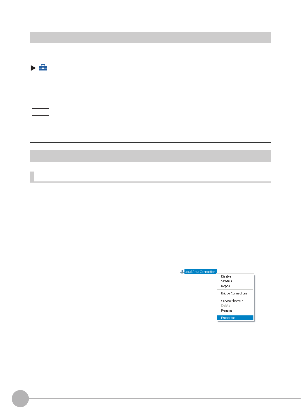
Connecting to Sensors from External Devices Such as PLCs
Set the IP address of the Sensor according to the network where the external devices, such as PLCs, are
connected.
(Setup Mode) − [Sensor settings] − [Network] − [Ethernet] − [IP address setting]
1 Press [Fixed].
2 Set the IP address and subnet mask according to the network where the external devices, such
as PLCs, are connected.
Note
If you connect OMRON CS/CJ-series PLCs to the Ethernet, the following default IP addresses are assigned to the
PLCs.
• IP address: 192.168.250.node_address
Connecting to Sensors from a Computer Using the PC Tool
Configurations Consisting of Only Sensors and a Computer (PC Tool)
If the configuration consists only of Sensors and a Touch Finder, set the network settings on the computer as
described below.
(No IP address settings are required on the Sensors.)
The following procedure is for Windows XP.
1 Select [Control Panel] from the Windows Start Menu.
2 Click [Network and Internet Connections] in the control
3 Right-click the [Local Area Connection] Icon and select
54
Setting Up Ethernet
panel and then double-click [Network Connections].
[Properties].
FQ2-S4 User’s Manual
Page 57

4 On the [General] Tab Page, double-click Internet Proto-
col (TCP/IC).
5 Select the Use the following IP address Option and en-
ter the following IP address and subnet mask.
• IP address: 10.5.5.101
• Subnet mask: 255.255.255.0
6 Click the [OK] Button. This completes the settings.
2
Installation and Connections
Connections on Existing Networks
Set the Ethernet settings of the Sensors and the computer (PC Tool) to the same settings as the existing
network. Refer to Connecting to Sensors from the Touch Finder on page 53 for the IP address settings in the
Sensors.
Note
• If you connect the PC Tool to a Sensor on a different network through a router, set fixed IP addresses.
• If you use an EtherNet/IP connections, set fixed IP address for the Sensors.
FQ2-S4 User’s Manual
Setting Up Ethernet
55
Page 58

MEMO
56
Setting Up Ethernet
FQ2-S4 User’s Manual
Page 59

Taking Images
3-1 Selecting a Sensor for Configuration. . . . . . . . . . . . . . . . . . . . . . . . . . 58
3-2 Setting Conditions for Taking Images . . . . . . . . . . . . . . . . . . . . . . . . . 59
3-3 Adjusting Image Quality . . . . . . . . . . . . . . . . . . . . . . . . . . . . . . . . . . . . 60
3-4 Adjusting the Timing of Taking Images . . . . . . . . . . . . . . . . . . . . . . . . 67
3-5 Adjusting the Images That Were Taken . . . . . . . . . . . . . . . . . . . . . . . . 69
3
Taking Images
Page 60

3-1 Selecting a Sensor for Configuration
If multiple Sensors are connected to a single Touch Finder or computer, a list of the Sensors that are connected
is displayed by default. Use the following procedure to change to the Sensor to set up.
1 Press − [Switch Sensor].
2 Press the image of the Sensor to be set up.
will be displayed for Sensors that are not yet set.
Note
Once the Touch Finder detects and records a Sensor, the display order for showing more than one Sensor is fixed. Even if the system
configuration is changed to reduce the number of Sensors, the previous display location will remain for Sensors that were removed.
To update displays of multiple Sensors to the current connection sta-
tus, press [ ] - [Auto connect] on the right of the display in step 2, to
automatically reconnect.
3 Press − [Sensor settings] to return to Setup
Mode.
4 Press [Yes].
Note
There are different methods that you can use to connect the Sensors. For example, you can automatically connect to
the Sensors that are recognized by the Touch Finder, or you can manually register the Sensors to connect.
7-5 Connecting to More Than One Sensor: p. 248
58
Selecting a Sensor for Configuration
FQ2-S4 User’s Manual
Page 61

3-2 Setting Conditions for Taking Images
You can set the conditions for taking images to use in inspections.
To enable accurate judgements, the following adjustments are made for the conditions for taking images and
the images themselves.
Taking Clear Images (Camera Setup)
Adjusting the Focus
Adjust the focus of the Lens.
Taking Bright Images of Dark Objects and Taking Clear Images of Moving Objects
Adjust the shutter speed and gain.
Improving the Image Quality of Metallic and Other Shiny Surfaces (HDR)
Make adjustments for shiny objects or metallic surfaces.
For a Sensor with built-in lighting, attach a polarizing filter to cut specular reflections.
Adjusting the Colors of the Image (White Balance)
Adjust the white balance so that the colors match those of the actual measurement object.
p. 60
p. 64
p. 65
p. 66
3
Taking Images
Adjusting the Timing of Taking Images (Trigger Setting)
Trigger Delay
Adjust the timing of taking an image with the Sensor.
p. 67
Adjusting the Images That Were Taken (Image Adjustment)
Filtering the Images (Filter Items)
Apply filters to adjust the images that were taken.
Compensating for Position Offset (Position Compensation Items)
Recognize measurement objects that are not in a consistent location and move them to the center of the image.
p. 70
p. 75
FQ2-S4 User’s Manual
Setting Conditions for Taking Images
59
Page 62

3-3 Adjusting Image Quality
Adjusting the Focus
[Image] − [Camera setup]
1 Display the Camera Setup Display.
The focus can be seen as a numerical value. The higher
the value, the better the focus.
Focus Level
2 Adjust the focus of the Sensor while checking the im-
age and focus value on the Touch Finder.
For a Sensor with Built-in Lighting, manually adjust the
focus using the focus adjustment screw on the Sensor.
In the default settings, the field of view is set to the narrowest setting. For a Sensor with a C-mount, use the focus ring on the lens to adjust the focus of the image.
3 Press [Back].
Important
• Turn the focus adjustment screw clockwise or counterclockwise a little bit to make sure that it has not already
reached the dead stop. Do not force the screw if it does not rotate anymore. This will damage the Sensor.
• Do not turn the focus adjustment screw with a force that is greater than 0.1 N·m. This may damage it.
Focus adjustment screw
Turn clockwise to focus on closer objects.
(The field of view will
narrow.)
Turn the screw counterclockwise
to focus on objects at a distance.
(The field of view will widen.)
Sensor with Built-in Lighting
60
Adjusting Image Quality
FQ2-S4 User’s Manual
Page 63

Adjusting Image Brightness with External Lighting
You can adjust image brightness with external lighting or by setting the Sensor sensitivity.
Using a Strobe Trigger Signal to Control External Lighting
If a Data Unit is connected, you can change the output time of the strobe trigger signal (STGOUT) to adjust the
brightness.
Changing the Output Timing and Output Time of the STGOUT Signal: p. 316
Adjusting the Brightness
You can adjust the shutter speed/gain or the brightness to make images brighter. The setting method depends
on whether HDR Mode is ON or OFF. The setting methods are described below.
HDR Function: p. 65
Important
The exposure time will be longer for higher values of the shutter speed or brightness. This may cause the
image to blur if the object is moving fast. If the Sensor is used on a high-speed line, check that the images are
not blurred under actual operating conditions.
Brightness Correction Mode (FQ2-S4@@@@@/FQ2-S4@@@@@-M)
If the brightness changes inconsistently with each image, turn ON the Brightness Correction Mode.
When HDR is ON: [Brightness] − − [Brightness correction]
When HDR is OFF: [Gain] − − [Brightness correction]
When the Brightness Correction Mode is ON, the brightness will be consistent but the timing when images are
taken will be delayed by 25 ms. Make sure that appropriate images of the measured objects are taken when the
Brightness Correction Mode is ON.
Timing Chart When the Brightness Correction Mode Is ON
Taking images begins 25 ms
after the TRIG signal is input.
TRIG signal
(Brightness
Correction ON)
BUSY signal
ON
OFF
ON
OFF
ON for 1 ms min.
ON while the measurement
process is being executed.
3
Taking Images
Reference Timing Chart When the Brightness Correction Mode Is OFF: p. 282
Important
If the gain is increased, the brightness will not be stable and measurement values may be inconsistent. We
recommend that you turn ON the Brightness Connection Mode.
FQ2-S4 User’s Manual
Adjusting Image Quality
61
Page 64

When HDR Is OFF
The brightness of the image is adjusted by adjusting the shutter speed. If the brightness cannot be improved by
adjusting the shutter speed, the gain is adjusted.
Relationship between the Shutter Speed/Gain and the Image Brightness
Dark
Brightness of image
Bright
1/60000
Shutter
speed
0
Gain
Note
• Adjust the shutter speed not only to adjust the brightness of the image, but also to adjust for the travel speed of
the measurement object.
Taking Clear Images of Moving Objects: p. 64
• Increasing the gain will make the image brighter, but it will also reduce image quality to the point that the noise
component in the images will stand out. Select a suitable factor for the inspection.
1/1
10
[Image] − [Camera setup]
1 Press [ ] − [Shutter speed] on the right of the dis-
play.
2 Move the bar to the left or right to adjust the shutter
speed.
Moving it to the left will make the shutter speed slower
and the image brighter. Moving it to the right will make the
shutter speed faster and the image darker.
3 Press [OK].
If you cannot obtain the required brightness by adjusting
the shutter speed, adjust the gain
4 Press [ ] − [Gain] on the right of the display.
5 Move the bar to the left or right to adjust the gain.
Moving it to the right will increase the gain and make the
image brighter. Moving it to the left will reduce the gain
and make the image darker.
6 Press [OK].
7 Press [Back].
62
Adjusting Image Quality
FQ2-S4 User’s Manual
Page 65

Parameter Setting Description
Shutter speed Range:
Gain For FQ2-S4@@@@@-08@, FQ2-S4@-@@@
Important
• To ensure stable operation when the FQ2-S4
For FQ2-S4@-@@@
1/1 to 1/60,000
For FQ2-S4@@@@@-08@
1/1 to 1/60,000
1/250 to 1/60,000 (for Cameras with Built-in Lighting)
(FQ2-S4@@@@@ or FQ2-S4@@@@@-M only)
1/1 to 1/50,000
1/250 to 1/50,000 (for Cameras with Built-in Lighting)
Default: 1/250
Range: 0 to 10
Default: 0
For FQ2-S4@@@@@@, FQ2-S4@@@@@@-M
Range: 16 to 64
Default: 16
@@@@@
/FQ2-S4
@@@@@
If the shutter speed is slow, the image will be
bright. If the shutter speed is fast, the image
will be dark.
If the gain is high, the image will be bright. If
the gain is low, the image will be dark.
-M is connected, we recommend that you
set the gain to 16.
• If the recommended value is exceeded, the brightness will not be stable and measurement values may be
inconsistent. We recommend that you turn ON the Brightness Connection Mode.
• If a slow shutter speed (1/1 to 1/10) and a high gain are set, fixed-pattern noise (fleck and striped noise) will
sometimes occur. Be sure to thoroughly check the images and the measurement results when you set the
shutter speed and gain.
When HDR Is ON
3
Taking Images
Set the brightness adjustment value. The higher the brightness adjustment value, the brighter the image.
Dark
Brightness of image
0
Bright
100
[Image] − [Camera setup]
1
Press [ ] − [Brightness] on the right side of the display.
2 Move the bar to the left or right to adjust the bright-
ness.
Moving it to the right will make the image brighter, while
moving it to the left will reduce the brightness of the image.
3 Press [OK].
FQ2-S4 User’s Manual
Adjusting Image Quality
63
Page 66

Taking Clear Images of Moving Objects
For quick moving objects, the effect of blurring can be reduced by decreasing the shutter speed.
In HDR Mode, set the brightness value to a low setting.
• Relationship between Shutter Speed and the Brightness Adjustment Value in HDR Mode
Fast
1/60,000 1/250
Moving speed
Brightness
Shutter speed
Slow
1000
Refer to the following page for the setting methods for the shutter speed and brightness.
Adjusting the Brightness: p. 61
64
Adjusting Image Quality
FQ2-S4 User’s Manual
Page 67

Important
The lower the shutter speed/gain and brightness settings are, the darker the image becomes. If the Sensor is
used in a dark environment, make sure that the darkness of the image does not cause the measurements to be
unstable.
Improving the Image Quality of Metallic and other Shiny Surfaces
When objects with shiny surfaces are being measured, the lighting may be reflected off the surface and affect
the image.
To remove reflections, one of the following two functions can be used.
Function Description
HDR (High Dynamic Range) If objects have contrasting light and dark areas, the dynamic range can be made wider to
Polarizing filter (for Sensors
with Built-in Lighting)
HDR Function
The HDR function is used for objects that have a large difference between light and dark areas. For this kind of
object, clear images cannot be achieved with the standard brightness setting. The HDR function combines
several images of different brightnesses (shutter speed) so that the resulting image has a lower degree of
contrast and can be measured stably for the desired characteristic.
Inputting Images with a Limit Range of Brightness
improve the quality of the images.
Specular reflections can be eliminated from an image by attaching a polarizing filter to the
Sensor.
If the measurement object must be moving, use a polarizing filter. Also, if reflections cannot be sufficiently removed by using the HDR function, use a polarizing filter as well.
Combining Images to Create an Image
with a Wide Dynamic Range
3
Taking Images
Observe the following precautions.
• Use the HDR function only for objects that are not moving to avoid image blurring.
Several images are taken with different shutter speeds and combined. If the object moves while the image
is being taken, the image will become blurred.
• Images with different brightnesses are combined, so the resulting image will have a lower degree of contrast.
[Image] − [Camera setup]
1 Press [ ] − [HDR] on the right side of the display.
2 Set the best level for the HDR Mode.
As shown below, the higher the level, the wider the combined dynamic range will be.
Level 1
Level 2
Level 3
Level 4
Dark
FQ2-S4 User’s Manual
Bright
Dark
Bright
Adjusting Image Quality
65
Page 68

Using a Polarizing Filter (Only for Sensors with Built-in Lighting)
Specular reflections can be eliminated from an image by attaching an FQ-XF1 Polarizing Filter to the Sensor.
Observe the following precautions.
• The image will be darker compared to when no filter is used.
• If the image becomes too dark, adjust the brightness.
p. 61
• Mounting the Filter
1 Hook the filter in the hole at the top of the Sensor.
2 Using the top section as a pivot point, pull down the
filter so that it attaches to the Sensor.
Adjusting the Colors of the Image (White Balance) (Only for Sensors with Color Cameras)
If external lighting is used, the image may appear as having different colors than the actual object. If this is the
case, adjust the white balance.
If the lighting built in to the Sensor is used, the white balance is already adjusted. No setting is required in this
case.
[Image] − [Camera setup]
1 Input a picture of white paper or cloth.
2 Press [ ] – [White balance] on the right side of the
display.
3 Press the [Auto] Button. The Sensor will automatical-
ly adjust the colors.
4 Move the bar to the left (light) or right (dark) to fine-
tune the colors.
5 Press [OK].
66
Adjusting Image Quality
FQ2-S4 User’s Manual
Page 69

3-4 Adjusting the Timing of Taking Images
Delaying the Image Capture Timing from the Trigger Input
If the measurement object is moving, the position in the image of the feature that is to be measured will depend
on the timing of the trigger signal. A delay can be applied from when the trigger (i.e., the TRIG signal) is input
until when the image is taken to synchronize the timing of image capture with the speed of moving objects. If
the object position varies in the image, this delay cannot be used to make the object position more stable.
When you use a trigger delay with external lighting, you will also need to adjust the timing to turn ON external
lighting.
Delay time
Delay from when the trigger is input until
when Sensor input is started.
3
Taking Images
Trigger input Sensor
[Image] − [Trigger setup] − [Trigger delay]
1 A TRIG signal is input.
Images are input continuously.
2 Select the image with the measurement object in the
center using and .
3 Press the image.
4 Press [OK].
Note
The delay time can be set using the adjustment bar or by directly entering a value.
Move the bar to the left or right.
Or
Directly input the delay time.
FQ2-S4 User’s Manual
Adjusting the Timing of Taking Images
67
Page 70

Adjusting External Lighting Timing
When you use a trigger delay, you must adjust the timing to turn ON external lighting so that it matches the
trigger delay timing.
Using a Strobe Trigger Signal to Control External Lighting
If a Sensor Data Unit is connected, you can change the output time of the strobe trigger signal (STGOUT) to
adjust the timing of the external lighting.
Changing the Output Timing and Output Time of the STGOUT Signal: p. 316
[Image] − [Camera setup] − [ ] − [Lightning control]
Preventing Mutual Interference of Multiple Sensors
When the same trigger signal is input to multiple Sensors, the lighting from one Sensor may affect the
measurements of the other Sensors. This is called mutual interference. This kind of interference can be
prevented offsetting the image input timing of each Sensor from when the trigger signal is received.
Example:
A trigger (i.e., the TRIG signal) is input to Sensor 0 and Sensor 1 at the same time.
Sensor 0
Trigger Sensor
Sensor 1
Sensor 0
Sensor 1
Sensor 0 immediately begins image input when the trigger is input.
Sensor 1 begins image input after the specified time has passed.
1 Change to the setup for to Sensor 1.
p. 58
2 Press [Image] – [Trigger setup] – [Trigger delay].
3 Set the trigger input delay time for Sensor 1.
p. 67
TRIG signal
No trigger delay
Sensor 1
trigger delay
Timing of taking the image
Timing of taking the image
Important
The delay time for preventing mutual interference must be longer than the shutter time.
When the lighting built into the Sensor is used, the shutter time is 4 ms max. Therefore make the delay at least
4 ms.
68
Adjusting the Timing of Taking Images
FQ2-S4 User’s Manual
Page 71

3-5 Adjusting the Images That Were Taken
Image Adjustment
You can adjust the image that is taken by the Sensor to make it easy to measure.
There are mainly the following two types of items that you can use to adjust the image.
• Filtering the Images (Filter Items)
These items filter the image by eliminating image noise with filters to make them suitable for measurement.
• Compensating for Position Offset (Position Compensation Items)
These items compensate for offset in the position or orientation of the image.
You can combine several filter items and position compensation items to adjust the image that was taken. (You
can use a total of up to eight filter and position compensation items combined.)
3
Flow of Image Adjustment
The image that is taken by the Camera (called the Camera image) is adjusted in the order that the filter and
position compensation items are registered.
Note
You can specify the order of image adjustment by registering the items in the desired order, but you cannot change
the order of the items after you register them.
Image is taken on TRIG signal.
Camera image
Processed
image
(process 0)
(The image that is taken by the Camera.)
0: Median (filter item)
Source image: Camera image [Camera]
Taking Images
Image
adjustment
Measurements are performed
FQ2-S4 User’s Manual
Processed image
(processes 0 and
1)
Processed image
(processes 0, 1,
and 2)
with inspection items.
1: Dilate (filter item)
Source image: Previous image [Prev.]
2: Search Position Compensation (position compensation item)
Source image: Previous image [Prev.]
Adjusting the Images That Were Taken
69
Page 72

Note
Specify the Camera image for the first filter item for image processing.
If you execute more than one filter item for the image, set the source image for the other filter items to the previous
image.
Also, you can perform image processing with filter items only to enable processing with position compensation
items.
In that case, only the position information from position compensation is applied to the image to be measured.
For details, refer to Using Filter Items for Processing with Position Compensation Items on page 77.
Filtering the Images (Filter Items)
You can filter the images that are taken by the Camera to make them easier to measure.
This is used in the following cases.
• To cut unnecessary backgrounds so that they are not measured
• To remove noise
• To stably find the edges of marks when other edges have been clearly extracted
Applicable Filters
Selected filter item Description
Color Gray Filter (only for Sensors with Color Cameras)
Converts an image that was input from a Color Camera to a monochrome image.
Example: You can extract an image that contains only a specific color.
→
Extracting an Image That Contains Only Red
Note
• This inspection item cannot be used for monochrome images. An NG (image error)
will result if you use it for a monochrome image.
• All inspection items after the Color Gray Filter item will be performed in the same way
as when a Monochrome Camera is connected.
Weak Smoothing Used when there are minor irregularities in the measurement object.
Strong Smoothing
Dilate Used when there is dark noise.
Erosion Used when there is bright noise.
Median Used when there are minor irregularities in the measurement object.
Extract Edges Extracts image edges between light and dark.
Extract Horiz. Edges
(extract horizontal edges)
Extract vertical edges Extracts vertical edges between light and dark in the image.
Enhance edges Enhances image edges between light and dark.
The image is feathered to reduce unevenness.
Dark noise is removed by dilating bright places.
Bright noise is removed by eroding bright places.
Unevenness is reduced while maintaining outlines.
Extracts horizontal edges between light and dark in the image.
70
Adjusting the Images That Were Taken
FQ2-S4 User’s Manual
Page 73

Selected filter item Description
Background Suppression Extracts a specific range of brightness to increase the image contrast and suppress the unnecessary
background.
Example: Increasing Contrast
→
Any areas that are outside of the specified range of brightness are removed as the background.
Also, the brightness within the specified range is converted to 255 levels to enhance the contrast.
Setting Filter Items
[Image] − [Image adjustment]
1 Press an unused number and then press [Add filter].
2 Press the filter item to use.
3 Make any detailed settings as required for the filter.
Refer to the detailed settings for each of the following filter items.
4 Press [OK].
5 Press [Back].
6 Make any the following settings as required for each
filter item.
• Setting the Source Image for Filtering
p. 71
• Setting the Region to Filter
p. 72
• Setting the Filter Type (for Color Gray Filter Only)
p. 72
• Setting the Brightness Range to Extract (for Background Suppression Item Only)
p. 73
3
Taking Images
Setting the Image to Filter (Source Image)
You must set the image to which the filter is to be applied.
[Image] − [Image adjustment] − [Add filter] − (Filter item to select)
1 Press [ ] − [Source image] on the right of the display.
2 Set the source image to [Camera] or [Prev.].
Parameter Setting Description
Source image Camera (camera image) The filter is applied to the image that is taken by the Camera.
Prev. (previous image) The filter is applied to the image that resulted from the previous filter items or posi-
FQ2-S4 User’s Manual
tion compensation items in the processing order.
Adjusting the Images That Were Taken
71
Page 74

Setting the Region to Filter
You can specify the region to which to apply the filter.
This setting does not exist in the Color Gray Filter item.
[Image] − [Image adjustment] − [Add filter] − (Filter item to select)
1 Press [ ] − [Filter region] on the right of the display.
2 Adjust the size and position of the region to which
the filter is to be applied.
To fine-tune the region, press [ ]
right of the display to display the console. This will allow
you to change the coordinates of the rectangle at the pixel level.
− [Console] on the
Drag to move the region.
Drag a corner to size the rectangle.
Setting the Filter Type (for Color Gray Filter Only)
You can specify the ranges of colors to which the Color Gray Filter item is applied.
[Image] − [Image adjustment] − [Add filter] − [Color Gray Filter]
1 Press [ ] − [Filter type] on the right of the display.
2 Set the filter type to either [RGB] or [HSV].
Parameter Description
RGB (default) The red, green, and blue extraction ranges are
HSV The extracted color ranges are specified with
3
Press [ ] − [Filter settings] on the right of the display.
specified.
the hue and chroma (saturation).
4 Make the detailed filter settings.
•RGB
Select the type of color filter to use.
If you select [Custom filter], set the gains for red, green,
and blue.
•HSV
Set the following ranges: [Std. Hue], [Hue range], and
[Chroma].
5 Press [OK].
6 Press [Back].
72
Adjusting the Images That Were Taken
FQ2-S4 User’s Manual
Page 75

•RGB
Parameter Setting Description
Filter settings • Red filter (default)
R Range: 0.0001 to 9.9999
G Range: 0.0001 to 9.9999
B Range: 0.0001 to 9.9999
• Green filter
• Blue filter
• Cyan filter
• Magenta filter
• Yellow filter
• Brgt.F (brightness filter) (R+G+B)
• Brgt.F (brightness filter) (R+2G+B)
• Custom filter
Default: 0.3000
Default: 0.5900
Default: 0.1100
These filters achieve the same effect as when using the selected optical
filter.
These are the RGB gain settings for a custom filter.
Increase the gain to increase the density of that color component.
You can set the gains only if [Custom filter] is selected in the filter settings.
•HSV
Parameter Setting Description
Std. Hue (standard hue)
Hue range Range: 10 to 180
Chroma (saturation)
Range: 0 to 359
Default: 0
Default: 90
Range: 0 to 255
Defaults: Lower limit: 0, Upper limit: 255
Sets the standard hue for the HSV filter.
The density will decrease as the difference between the hue and the
standard hue increases.
Sets the hue range for the HSV filter.
The hue range centered on the standard hue is divided into 255 levels to
find the difference in the hue. Hues that are outside the hue range will
have a density of 0.
Set the upper and lower limit values for the chroma (saturation).
3
Taking Images
Setting the Brightness Range to Extract (for Background Suppression Item Only)
The range in which to enhance the contrast and the brightness range to extract are set for the Background
Suppression item. The Background Suppression item works as described below to suppress the background
for the specified brightness range.
• Enhancing Contrast
The range of the input brightness that is within the specified brightness range (0 to 255) is converted to 255 levels
to enhance the contrast.
• Background Suppression
Input values from 0 to the lower limit are converted to level 0 and input values between the upper limit and 255 are
converted to level 255 to remove as the background any places that are not within the specified brightness range.
255
Output value
0
Lower limit
0
You can use either of the following methods to set the upper and lower limits of the brightness range to extract
with the Background Suppression item.
Upper limit
Input value
255
FQ2-S4 User’s Manual
Adjusting the Images That Were Taken
73
Page 76

• Enhancing the Contrast of a Specific Area
You specify the location on the image to enhance the contrast.
[Image] − [Image adjustment] − [Background Suppression] − [Modify]
1 Press [ ] − [Suppression level] on the right of the
display.
2 Drag on the image to specify the location to empha-
size the contrast.
The contrast in the specified range will be reset to between 0 and 255.
3 Press [OK].
4 Press [Back].
• Extracting Only a Specified Range of Brightness
You set the upper and lower limits of the brightness range to extract with the Background Suppression item.
[Image] − [Image adjustment] − [Background suppression] − [Modify]
1 Press [ ] − [Suppression level] on the right of the
display.
2 Press [ ] − [RGB setting] on the right of the display.
3 Select the method to use to specify the brightness
range. (This setting applies to Sensors with Color
Cameras only.)
• Common RGB Settings
Set the upper and lower limit values of the brightness
range. The same limits will be used for all RGB colors.
• Individual RGB Settings
Set the upper and lower limit values of the brightness
range for each RGB color. Press [R], [G], and [B] and
set the upper and lower limits for each of them.
4 Set the upper and lower limit values of the brightness
range. (for Sensors with Monochrome Cameras (or
after a Color Gray Filter))
Lower limit
Upper limit
5 Press [Back].
6 Press [OK].
7 Press [Back].
74
Adjusting the Images That Were Taken
FQ2-S4 User’s Manual
Page 77

Parameter Setting Description
Common (common RGB
setting)
Individual (individual
RGB settings)
Brightness range (for
Sensors with Monochrome Cameras)
Range: 0 to 255
Defaults: Lower limit: 0, Upper limit: 255
Range: 0 to 255
Defaults: Lower limit: 0, Upper limit: 255
Range: 0 to 255
Defaults: Lower limit: 0, Upper limit: 255
Set the upper and lower limit values of the background suppression level. The same limits will be used for all RGB colors.
The range from the specified lower to upper limits is converted to
0 to 255.
Set the upper and lower limit values of the background suppression level for each RGB color.
The range from the specified lower to upper limits is converted to
0 to 255.
The specified range is converted to 0 to 255.
Measurement Data That Can Be Used for External Outputs and Calculations
The following values can be used as measurement data and output to external devices via Ethernet or used in
calculations. Measurement data can be specified for each filter item.
Expression text string Data name Description Data range
JG Judgement This is the judgement
result.
−2: No judgement (not measured),
0: Judgement is OK,
−1: Judgement is NG
Compensating for Position Offset (Position Compensation Items)
Use position compensation items if the position or orientation of the measurement object is not consistent.
When you use a position compensation item, the offset between the reference position and the position of the
object is calculated and the position of the measurement region is corrected before measurements are
performed.
Applicable Position Compensation Items
There are the following two types of position compensation items that vary in the method that is used to detect
the object.
Ty pe Description
Model (model position compensation)
Edge position comp. (edge position
compensation)
A search is made for a characteristic pattern to detect and correct the position.
• Shape Sear. pos. comp. (Shape Search Position Compensation)
• Search position comp. (Search Position Compensation)
The color distribution or density changes in the object are used to detect and correct the position.
• Edge position comp. (Edge Position Compensation)
• 2Edge position comp. (Two-edge Position Compensation)
• 2Edge midpoint comp. (Two-edge Midpoint Compensation)
• Edge rot. pos. comp. (Edge Rotation Position Compensation)
3
Taking Images
FQ2-S4 User’s Manual
Adjusting the Images That Were Taken
75
Page 78

• Features of the Position Compensation Items
The position is offset in
only one direction.
The position is offset in
two directions.
The measurement object is
not at an angle.
The position needs to be
corrected to the midpoint
between two edges.
There is a characteristic
pattern.
Edge Position Compensation
The position is corrected in either
the X or Y direction.
Edge Position
Compensation: p. 81
Two-edge Position Compensation
The position is corrected at the
same time in both the X and Y
directions.
Two-edge Position
Compensation: p. 82
Two-edge Midpoint Compensation
The positions of two edges are detected and
then the coordinates of the midpoint between
those two positions is used to correct the
position in either the X or Y direction.
Two-edge Midpoint Compensation
Search Position Compensation
An image pattern is recognized to
detect and correct the position.
Search Position
Compensation: p. 79
: p. 84
Shape Search Position Compensation
An image pattern is recognized to
There is a characteristic
pattern.
detect and correct the position.
Shape Search Position
Compensation: p. 78
The measurement object is
at an angle.
There is no characteristic
pattern.
Edge Rotation Position Compensation
The positions of two edges are
detected and the angle of the line
that connects those positions is
used to correct the position.
Edge Rotation Position
Compensation: p. 86
Applying the Results of Position Compensation
You can apply the results of position compensation either to the Camera image or to the previous image from
before position compensation was applied.
If you apply the results of position compensation to the Camera image, only the position information from
position compensation is applied to the image to be measured.
Using Filter Items for Processing with Position Compensation Items: p. 77
76
Adjusting the Images That Were Taken
FQ2-S4 User’s Manual
Page 79

• Setting the Image for Position Compensation
You can select the image to which to apply the results of position compensation processing.
You can set the image for position compensation for each position compensation item.
[Image] − [Image adjustment] − (Position compensation item name) − [Modify]
1 Press [Details] − [Scroll parameter]
2 Set the source image to [Camera] or [Prev.].
Parameter Setting Description
Source image Camera (camera
image)
Prev. (previous
image) (default)
• Using Filter Items for Processing with Position Compensation Items
To more effectively perform position compensation, filter items can be used to create an image specifically for
position compensation and then apply only the results of processing the position compensation to the image
that will be measured. The processing order of filter and position compensation items and the settings of the
source images are set up as shown below.
The results of processing the position compensation item is applied to the image that is taken
by the Camera.
This setting is used when filter items or other position compensation items have been used
specifically for the position compensation item.
Using Filter Items for Processing with Position Compensation Items: p. 77.
This setting is used when the processing results of the current position item are to be applied
to the image that results from previous filter items or other position compensation items.
3
Taking Images
Processing
order
1 0: Enhance edges (Edge
2 1: Search position comp. (Search
Camera image
(no processing)
Camera image
with results of
Search Position
Compensation
item
Image processing item Source image setting
Enhancement) (filter item)
Position Compensation) (position
compensation item)
Image is taken on TRIG signal.
If the source image is set to the camera image.
the results of position compensation are applied to the
Camera image.
Source image: Camera image
Camera image (image for processing) → Processed image (results of processing)
Source image: Camera image
Previous image (image for processing) → Camera image (results of processing)
0: Edge Enhancement (filter item)
1: Search Position Compensation
(position compensation item)
Measurements are performed with inspection items.
FQ2-S4 User’s Manual
Adjusting the Images That Were Taken
77
Page 80

Shape Search Position Compensation
With this position compensation item, an image pattern is registered in advance. When the registered image
pattern is detected, the image is adjusted so that the image pattern is in the same position as when it was
registered.
This position compensation item performs the same type of processing as the Search Position Compensation
item, but it performs special processing for the shape of the image pattern.
Use this position compensation item to correct the position of a rotated image pattern.
[Image] − [Image adjustment]
1 Press an unused number and then press [Add pos.
comp.].
2 Press [Model] − [Shape Sear. pos. comp.]
3 Make any detailed settings as required for the posi-
tion compensation processing.
Refer to Detailed Settings for Shape Search Position
Compensation, below.
4 Press [OK].
5 Press [Back].
• Detailed Settings for Shape Search Position Compensation
The settings for the Shape Search Position Compensation item are almost the same as those for the Search
inspection item.
Only the [Sub-pixel] and the [Multi-point output] settings of the Search item are not included in the settings of
the Search Position Compensation item. Make the settings for teaching and the judgement conditions in the
same way as for the Search item. ( 4-8 Inspecting with the Search Inspection Item: p. 137) Also, the
following settings are included only in the Shape Search Position Compensation Item.
• Rotation
This setting is used to enable rotating the image to correct.
[Image] − [Image adjustment] − [Shape Sear. pos. comp.] − [Modify]
1 Press [Details] − [Model parameter]
2 Set [Rotation] to either [Yes] or [No].
Parameter Setting Description
Rotation No (default)
Ye s
• Source Image
You can select the image to which to apply the results of position compensation processing.
Applying the Results of Position Compensation: p. 76
• Interpolation
You can select the precision of position compensation.
78
Adjusting the Images That Were Taken
Specify whether to automatically create several patterns of rotated images and use
them to measure the image.
The processing time will increase if you enable rotation processing.
FQ2-S4 User’s Manual
Page 81

If you select [Bilinear], the precision of position compensation will increase.
[Image] − [Image adjustment] − [Shape Sear. pos. comp.] − [Modify]
1 Press [Details] − [Scroll parameter] − [Interpolation]
2 Set the interpolation to [Bilinear] or [None].
Parameter Setting Description
Interpolation Bilinear (default) Points are connected with lines to find approximations. This create smoother
None Position compensation is performed at the pixel level.
• Measurement Data That Can Be Used for External Outputs and Calculations
The following values can be used as measurement data and output to external devices via Ethernet or used in
calculations.
Expression text string Data name Description Data range
JG Judgement This is the judgement result. −2: No judgement (not measured),
DX Scroll X This is the amount of position compen-
DY Scroll Y This is the amount of position compen-
DT Scroll θ This is the amount of angular compen-
X Position X This is the X coordinate of the position
Y Position Y This is the Y coordinate of the position
TH Angle This is the angle at which the model
SX Reference X This is the X coordinate of the position
SY Reference Y This is the Y coordinate of the position
ST Reference angle This is the angle when the model was
CR Correlation This is the correlation. 0 to 100
images.
0: Judgement is OK,
−1: Judgement is NG
−99,999.9999 to 99,999.9999
sation for the X coordinate.
−99,999.9999 to 99,999.9999
sation for the Y coordinate.
−180 to 180
sation, θ.
−99,999.9999 to 99,999.9999
where the model was found.
−99,999.9999 to 99,999.9999
where the model was found.
−180 to 180
was found.
−99,999.9999 to 99,999.9999
where the model was registered.
−99,999.9999 to 99,999.9999
where the model was registered.
−180 to 180
registered.
3
Taking Images
Search Position Compensation
With this position compensation item, an image pattern is registered in advance. When the registered image
pattern is detected, the image is adjusted so that the image pattern is in the same position as when it was
registered.
This position compensation item performs the same type of processing as the Shape Search Position
Compensation item, but it performs processing to detect differences in colors and patterns in addition to
processing for image pattern shapes.
Note
To perform position compensation for a rotated image pattern, use the Shape Search Position Compensation item.
[Image] − [Image adjustment]
1 Press an unused number and then press [Add pos. comp.].
FQ2-S4 User’s Manual
Adjusting the Images That Were Taken
79
Page 82

2 Press [Model] − [Search position comp.]
3 Make any detailed settings as required for the position compensation processing.
Refer to Detailed Settings for Search Position Compensation, below.
4 Press [OK].
5 Press [Back].
• Detailed Settings for Search Position Compensation
The settings for the Search Position Compensation item are almost the same as those for the Search
inspection item. Only the [Multi-point output] setting of the Search item is not included in the settings of the
Search Position Compensation item. Make the settings for teaching and the judgement conditions in the same
way as for the Search item. ( 4-8 Inspecting with the Search Inspection Item: p. 137)
Also, the following settings are included only in the Search Position Compensation Item.
• Source Image
You can select the image to which to apply the results of position compensation processing.
Applying the Results of Position Compensation: p. 76
• Interpolation
You can select the precision of position compensation.
If you select [Bilinear], the precision of position compensation will increase.
[Image] − [Image adjustment] − [Search position comp.] − [Modify] − [Details] −
[Scroll parameter] − [Interpolation]
The settings are the same as those for the Shape Search Position Compensation item.
Interpolation: p. 78
• Measurement Data That Can Be Used for External Outputs and Calculations
The following values can be used as measurement data and output to external devices via Ethernet or used in
calculations.
Expression text string Data name Description Data range
JG Judgement This is the judgement result. −2: No judgement (not measured),
DX Scroll X This is the amount of position com-
DY Scroll Y This is the amount of position com-
X Position X This is the X coordinate of the position
Y Position Y This is the Y coordinate of the position
SX Reference X This is the X coordinate of the position
SY Reference Y This is the Y coordinate of the position
CR Correlation This is the correlation. 0 to 100
pensation for the X coordinate.
pensation for the Y coordinate.
where the model was found.
where the model was found.
where the model was registered.
where the model was registered.
0: Judgement is OK,
−1: Judgement is NG
−99,999.9999 to 99,999.9999
−99,999.9999 to 99,999.9999
−99,999.9999 to 99,999.9999
−99,999.9999 to 99,999.9999
−99,999.9999 to 99,999.9999
−99,999.9999 to 99,999.9999
80
Adjusting the Images That Were Taken
FQ2-S4 User’s Manual
Page 83

Edge Position Compensation
This position compensation item detects an edge in the set direction.
If the specified color is detected (or the specified density is detected for a Sensor with a Monochrome Camera),
it is recognized as an edge.
When an edge is recognized, the image is adjusted so that the edge appears at the position it was in when it
was registered.
Measurement region
Edge search direction
3
Registered position of the edge
Color of edge to be found
[Image] − [Image adjustment]
The image is adjusted so that the edge
appears at the position it was in when it
was registered.
1 Press an unused number and then press [Add pos. comp.].
2 Press [Edge] − [Edge position comp.].
3 Make any detailed settings as required for the position compensation processing.
Refer to Detailed Settings for Edge Position Compensation, below.
4 Press [OK].
5 Press [Back].
• Detailed Settings for Edge Position Compensation
The settings for the Edge Position Compensation item are almost the same as those for the Edge Position
inspection item.
Make the settings for teaching and the judgement conditions in the same way as for the Edge Position
inspection item. ( 4-11 Inspecting with the Edge Position Inspection Item: p. 162)
However, the following settings are included only in the Edge Position Compensation Item.
• Source Image
You can select the image to which to apply the results of position compensation processing.
Taking Images
Applying the Results of Position Compensation: p. 76
• Interpolation
You can select the precision of position compensation.
If you select [Bilinear], the precision of position compensation will increase.
[Image] − [Image adjustment] − [Edge position comp.] − [Modify] − [Details] - [Scroll parameter]
− [Interpolation]
The settings are the same as those for the Shape Search Position Compensation item.
Interpolation: p. 78
FQ2-S4 User’s Manual
Adjusting the Images That Were Taken
81
Page 84

• Measurement Data That Can Be Used for External Outputs and Calculations
The following values can be used as measurement data and output to external devices via Ethernet or used in
calculations.
Expression text string Data name Description Data range
JG Judgement This is the judgement result. −2: No judgement (not measured),
DX Scroll X This is the amount of position com-
DY Scroll Y This is the amount of position com-
X Position X (edge position X)This is the X coordinate of the mea-
Y Position Y (edge position Y)This is the Y coordinate of the mea-
SX Reference X This is the X coordinate of the edge
SY Reference Y This is the Y coordinate of the edge
pensation for the X coordinate.
pensation for the Y coordinate.
sured edge position.
sured edge position.
position when it was registered.
position when it was registered.
0: Judgement is OK,
−1: Judgement is NG
−99,999.9999 to 99,999.9999
−99,999.9999 to 99,999.9999
−99,999.9999 to 99,999.9999
−99,999.9999 to 99,999.9999
−99,999.9999 to 99,999.9999
−99,999.9999 to 99,999.9999
Two-edge Position Compensation
This position compensation item detects edges in two directions.
If the specified color is detected (or the specified density is detected for a Sensor with a Monochrome Camera),
it is recognized as an edge.
When an edge is recognized, the image is adjusted so that the edge appears at the position it was in when it
was registered.
Registered position
of the edge
Measurement region for edge 1
Edge search direction for edge 1
Measurement
region for edge 0
Edge search
direction for edge 0
[Image] − [Image adjustment]
1 Press an unused number and then press [Add pos. comp.].
2 Press [Edge] − [2Edge position comp.]
3 Make any detailed settings as required for the position compensation processing.
Refer to Detailed Settings for Search Position Compensation, below.
4 Press [OK].
5 Press [Back].
82
Adjusting the Images That Were Taken
Color of edge to be found
The image is adjusted so that the edge
appears at the position it was in when it
was registered.
FQ2-S4 User’s Manual
Page 85

• Detailed Settings for Two-edge Position Compensation
The settings for the Two-edge Position Compensation item are almost the same as those for the Edge Position
inspection item.
Make the settings in the same way as for the Edge Position inspection item. ( 4-11 Inspecting with the
Edge Position Inspection Item: p. 162)
However, the following settings are included only in the Edge Position Compensation Item.
• Teaching
Set the measurement regions and measurement directions for both edge 0 and edge 1.
[Image] − [Image adjustment] − [2Edge position comp.] − [Modify] − [Basic]
1 Press [Teach].
2 Place the object that is to be used as the measure-
ment reference in front of the camera.
3 Move the rectangle to the location to be measured,
and then press [OK].
This concludes setting the measurement region and
edge search direction for edge 0.
Next, go to step 4 to set the measurement region and
edge search direction for edge 1.
4 Press [ ] − [Edge1 region] on the right of the dis-
play, move the rectangle to the location to be measured, and then press [OK].
5 Press [TEACH] on the lower right of the display.
The basic settings will be registered when teaching has
been completed.
6 Press [Back] to end teaching.
3
Taking Images
• Source Image
You can select the image to which to apply the results of position compensation processing.
Applying the Results of Position Compensation: p. 76
• Interpolation
You can select the precision of position compensation.
If you select [Bilinear], the precision of position compensation will increase.
[Image] − [Image adjustment] − [2Edge position comp.] − [Modify] − [Details] − [Interpolation]
The settings are the same as those for the Shape Search Position Compensation item.
Interpolation: p. 78
• Measurement Data That Can Be Used for External Outputs and Calculations
The following values can be used as measurement data and output to external devices via Ethernet or used in
calculations.
FQ2-S4 User’s Manual
Adjusting the Images That Were Taken
83
Page 86

Expression text string Data name Description Data range
JG Judgement This is the judgement result. −2: No judgement (not measured),
DX Scroll X This is the amount of position compen-
DY Scroll Y This is the amount of position compen-
X0 Edge 0 position X This is the X coordinate of the mea-
Y0 Edge 0 position Y This is the Y coordinate of the mea-
X1 Edge 1 position X This is the X coordinate of the mea-
Y1 Edge 1 position Y This is the Y coordinate of the mea-
SX0 Edge0 ref. position X
SY0 Edge0 ref. position Y
SX1 Edge1 ref. position X
SY1 Edge1 ref. position Y
(edge 0 reference
position X)
(edge 0 reference
position Y)
(edge 1 reference
position X)
(edge 1 reference
position Y)
sation for the X coordinate.
sation for the Y coordinate.
sured edge 0 position.
sured edge 0 position.
sured edge 1 position.
sured edge 1 position.
This is the X coordinate of the edge 0
position when it was registered.
This is the Y coordinate of the edge 0
position when it was registered.
This is the X coordinate of the edge 1
position when it was registered.
This is the Y coordinate of the edge 1
position when it was registered.
0: Judgement is OK,
−1: Judgement is NG
−99,999.9999 to 99,999.9999
−99,999.9999 to 99,999.9999
−99,999.9999 to 99,999.9999
−99,999.9999 to 99,999.9999
−99,999.9999 to 99,999.9999
−99,999.9999 to 99,999.9999
−99,999.9999 to 99,999.9999
−99,999.9999 to 99,999.9999
−99,999.9999 to 99,999.9999
−99,999.9999 to 99,999.9999
Two-edge Midpoint Compensation
This position compensation item detects edges in two directions.
If the specified color is detected (or the specified density is detected for a Sensor with a Monochrome Camera),
it is recognized as an edge. Two edge positions are detected.
The image is adjusted so that the coordinates of the midpoint position of a line that connects the two detected
edge positions matches the position when the edges were registered.
Midpoint position
Registered position
of the edge
Measurement
region for edge 0
Edge search
direction for edge 0
[Image] − [Image adjustment]
(center of a line that connects positions 1 and 2)
Detected edge positions (positions 1 and 2)
Measurement
region for edge 1
Edge search
direction for edge 1
Color of edge to be found
The image is adjusted so that the
midpoint appears at the position it
was in when it was registered.
1 Press an unused number and then press [Add pos. comp.].
84
Adjusting the Images That Were Taken
FQ2-S4 User’s Manual
Page 87

2 Press [Edge] − [2Edge midpoint comp.]
3 Make any detailed settings as required for the position compensation processing.
Refer to Detailed Settings for Two-edge Midpoint Compensation, below.
4 Press [OK].
5 Press [Back].
• Detailed Settings for Two-edge Midpoint Compensation
The settings for the Two-edge Midpoint Compensation item are almost the same as those for the Edge Position
inspection item.
Make the settings in the same way as for the Edge Position inspection item. ( 4-11 Inspecting with the
Edge Position Inspection Item: p. 162)
However, the following settings are included only in the Edge Position Compensation Item.
• Teaching
Set the measurement regions and measurement directions for both edge 0 and edge 1.
[Image] − [Image adjustment] − [2Edge midpoint comp.] − [Modify] − [Basic] − [Teach]
The settings are the same as those for the Two-edge Position Compensation item.
Teaching: p. 83
3
Taking Images
• Source Image
You can select the image to which to apply the results of position compensation processing.
Applying the Results of Position Compensation: p. 76
• Interpolation
You can select the precision of position compensation.
If you select [Bilinear], the precision of position compensation will increase.
[Image] − [Image adjustment] − [2ed. midp. comp.] − [Modify] − [Details] − [Scroll parameter] −
[Interpolation]
The settings are the same as those for the Shape Search Position Compensation item.
Interpolation: p. 78
• Measurement Data That Can Be Used for External Outputs and Calculations
The following values can be used as measurement data and output to external devices via Ethernet or used in
calculations.
Expression text string Data name Description Data range
JG Judgement This is the judgement result. −2: No judgement (not measured),
DX Scroll X This is the amount of position com-
DY Scroll Y This is the amount of position com-
X0 Edge 0 position X This is the X coordinate of the mea-
pensation for the X coordinate.
pensation for the Y coordinate.
sured edge 0 position.
0: Judgement is OK,
−1: Judgement is NG
−99,999.9999 to 99,999.9999
−99,999.9999 to 99,999.9999
−99,999.9999 to 99,999.9999
FQ2-S4 User’s Manual
Adjusting the Images That Were Taken
85
Page 88

Expression text string Data name Description Data range
Y0 Edge 0 position Y This is the Y coordinate of the mea-
X1 Edge 1 position X This is the X coordinate of the mea-
Y1 Edge 1 position Y This is the Y coordinate of the mea-
MX Midpoint X This is the X coordinate of the mea-
MY Midpoint Y This is the Y coordinate of the mea-
SX0 Edge0 ref. position X
SY0 Edge0 ref. position Y
SX1 Edge1 ref. position X
SY1 Edge1 ref. position Y
SMX Ref. Midpoint X (refer-
SMY Ref. Midpoint Y (refer-
(edge 0 reference
position X)
(edge 0 reference
position Y)
(edge 1 reference
position X)
(edge 1 reference
position Y)
ence midpoint X)
ence midpoint Y)
sured edge 0 position.
sured edge 1 position.
sured edge 1 position.
sured edge midpoint position.
sured edge midpoint position.
This is the X coordinate of the edge 0
position when it was registered.
This is the Y coordinate of the edge 0
position when it was registered.
This is the X coordinate of the edge 1
position when it was registered.
This is the Y coordinate of the edge 1
position when it was registered.
This is the X coordinate of the midpoint of the two edges when they
were registered.
This is the Y coordinate of the midpoint of the two edges when they
were registered.
−99,999.9999 to 99,999.9999
−99,999.9999 to 99,999.9999
−99,999.9999 to 99,999.9999
−99,999.9999 to 99,999.999
−99,999.9999 to 99,999.999
−99,999.9999 to 99,999.9999
−99,999.9999 to 99,999.9999
−99,999.9999 to 99,999.9999
−99,999.9999 to 99,999.9999
−9,999.9999 to 99,999.9999
−9,999.9999 to 99,999.9999
Edge Rotation Position Compensation
This position compensation item detects an edge in two directions.
If the specified color is detected (or the specified density is detected for a Sensor with a Monochrome Camera),
it is recognized as an edge. Two edge positions are detected.
The image is adjusted so that the two edge positions match the positions when the edge positions were
registered.
Two detected edge positions
Edge search
Edge search
direction for edge 1
direction
for edge 0
Measurement
region for edge 0
Measurement
region for edge 1
Color of edge
to be found
Registered position of the edge
The image is adjusted so that the two
detected edge positions appear at the
positions they were in when the edge
was registered.
[Image] − [Image adjustment]
1 Press an unused number and then press [Add pos. comp.].
2 Press [Edge] − [Edge rot. pos. Comp.]
3 Make any detailed settings as required for the position compensation processing.
Refer to Detailed Settings for Edge Rotation Position Compensation, below.
86
Adjusting the Images That Were Taken
FQ2-S4 User’s Manual
Page 89

4 Press [OK].
5 Press [Back].
• Detailed Settings for Edge Rotation Position Compensation
The settings for the Edge Rotation Position Compensation item are almost the same as those for the Edge
Position inspection item.
Make the settings in the same way as for the Edge Position inspection item. ( 4-11 Inspecting with the
Edge Position Inspection Item: p. 162)
However, the following settings are included only in the Edge Position Compensation Item.
• Teaching
• Measurement Regions and Measurement Directions
Set the measurement regions and measurement directions for both edge 0 and edge 1.
3
[Image] − [Image adjustment] − [Edge rot. pos. Comp.] − [Modify] − [Basic] − [Teach]
The settings are the same as those for the Two-edge Position Compensation item.
Teaching: p. 83
• Reference Angle
Set the reference angle.
Press [ ]
− [Edit Ref. angle] on the right of the display and set the angle.
• Source Image
You can select the image to which to apply the results of position compensation processing.
Applying the Results of Position Compensation: p. 76
• Interpolation
You can select the precision of position compensation.
If you select [Bilinear], the precision of position compensation will increase.
[Image] − [Image adjustment] − [2Edge position comp.] − [Modify] − [Details] − [Interpolation]
The settings are the same as those for the Shape Search Position Compensation item.
Interpolation: p. 78
Taking Images
• Measurement Data That Can Be Used for External Outputs and Calculations
The following values can be used as measurement data and output to external devices via Ethernet or used in
calculations.
Expression text string Data name Description Data range
JG Judgement This is the judgement result. −2: No judgement (not measured),
DT Scroll θ This is the amount of position compensa-
X0 Edge 0 position X This is the X coordinate of the measured
FQ2-S4 User’s Manual
tion.
edge 0 position.
0: Judgement is OK,
−1: Judgement is NG
−180 to 180
−99,999.9999 to 99,999.9999
Adjusting the Images That Were Taken
87
Page 90

Expression text string Data name Description Data range
Y0 Edge 0 position Y This is the Y coordinate of the measured
X1 Edge 1 position X This is the X coordinate of the measured
Y1 Edge 1 position Y This is the Y coordinate of the measured
TH Angle (edge angle) This is the measured angle. −180 to 180
SX0 Edg0 ref. pos. (edge 0
SY0 Edg0 ref. pos. Y (edge
SX1 Edg1 ref. pos. X (edge
SY1 Edg1 ref. pos. Y (edge
STH Reference angle This is the angle when the edge was reg-
reference position X)
0 reference position
Y)
1 reference position
X)
1 reference position
Y)
edge 0 position.
edge 1 position.
edge 1 position.
This is the X coordinate of the edge 0
position when it was registered.
This is the Y coordinate of the edge 0
position when it was registered.
This is the X coordinate of the edge 1
position when it was registered.
This is the Y coordinate of the edge 1
position when it was registered.
istered.
−99,999.9999 to 99,999.9999
−99,999.9999 to 99,999.9999
−99,999.9999 to 99,999.9999
−99,999.9999 to 99,999.9999
−99,999.9999 to 99,999.9999
−99,999.9999 to 99,999.9999
−99,999.9999 to 99,999.9999
−180 to 180
88
Adjusting the Images That Were Taken
FQ2-S4 User’s Manual
Page 91

Setting Up Inspections
4-1 Inspection Item Selection Guide. . . . . . . . . . . . . . . . . . . . . . . . . . . . . . 90
4-2 Setup Procedure for Inspection Items . . . . . . . . . . . . . . . . . . . . . . . . . 93
4-3 Configuring Inspection Items . . . . . . . . . . . . . . . . . . . . . . . . . . . . . . . . 94
4-4 Reading and Verifying Character Strings . . . . . . . . . . . . . . . . . . . . . . 96
4-5 Reading Bar Codes . . . . . . . . . . . . . . . . . . . . . . . . . . . . . . . . . . . . . . . 112
4-6 Reading 2D-codes . . . . . . . . . . . . . . . . . . . . . . . . . . . . . . . . . . . . . . . . 120
4-7 Reading DPM 2D Codes. . . . . . . . . . . . . . . . . . . . . . . . . . . . . . . . . . . . 128
4-8 Inspecting with the Search Inspection Item . . . . . . . . . . . . . . . . . . . 137
4-9 Inspecting with the Shape Search II Inspection Item . . . . . . . . . . . . 147
4-10 Inspecting with the Sensitive Search Inspection Item . . . . . . . . . . 155
4-11 Inspecting with the Edge Position Inspection Item . . . . . . . . . . . . 162
4-12 Inspecting with the Edge Width Inspection Item. . . . . . . . . . . . . . . 169
4-13 Inspecting with the Edge Pitch Inspection Item . . . . . . . . . . . . . . . 173
4-14 Inspecting with Color Data Inspection Item. . . . . . . . . . . . . . . . . . . 178
4-15 Inspecting with the Area Inspection Item . . . . . . . . . . . . . . . . . . . . 182
4-16 Inspecting with the Labeling Inspection Item . . . . . . . . . . . . . . . . . 188
4-17 Calculations and Judgements Using Inspection Item Data . . . . . . 197
4
Setting Up Inspections
Page 92

4-1 Inspection Item Selection Guide
The FQ2 Vision Sensor uses inspection items to judge measurement objects. There are eight different
measurement objects. Select the best inspection items for the characteristics of the measurement object that
are being judged.
Inspection Example Inspection
Judging according to character recognition Checking printed consume-by dates OCR p. 96
items used
Reference
OK
2012.10.01
2012.10.01
PQD/CE6800
Judging according to bar code Checking product information Bar code p. 112
NG
2012.11.01
OK
NG
12345 12346
Judging according to 2D-code Checking product information 2D-code p. 120
OK
NG
12345 12346
Judging according to DPM 2D-code Reading 3D codes for direct part
marking
OK
NG
2D-code
(DPM)
p. 128
12345 12346
4
Setting Up Inspections
Judging according to shapes Judging if there is a mark Search or
OK NG
ITJ
ITJ
ITJ
NG
Shape
Search II
OK
OK
Detecting positions with patterns Measurement objects of the same color and pattern can be
FQ2-S4 User’s Manual
detected.
OMRON
OMRON
Inspection Item Selection Guide
Search p. 137
p. 137
p. 147
90
Page 93

Inspection Example Inspection
Dividing the measurement area and judging
according to shapes for each division
Judging minute differences in printed
labels
OK
LED RADIATION
DO NOT STARE
INTO BEAM
Max.65mW
400-700nm
CLASS 2 LED PRODUCT
JIS C 6802:2005
items used
Sensitive
Search
NG
LED RADIATION
DO NOT STARE
INTO BEAM
Max.65mW
400-700nm
CLASS 2 LED PRODUCT
JIS C 6802:2005
Reference
p. 155
Judging according to positions Measuring the position offset of a
seal
Judging according to widths Measuring the width between lead
wires
Judging according to the features of parts of a
shape
Judging the number of pins Edge Pitch p. 147
OK NG
OK NG
OK
NG
Edge Position
Edge
Width
p. 162
p. 169
4
Setting Up Inspections
Judging according to colors Detecting parts Color Data p. 178
OK NG
NG
Judging according to sizes Judging if there is silver paste Area p. 182
OK NG
FQ2-S4 User’s Manual
Inspection Item Selection Guide
91
Page 94

Inspection Example Inspection
Judging according to shapes and quantities Judging the number of labels Labeling p. 188
items used
Reference
OK NG
92
Inspection Item Selection Guide
FQ2-S4 User’s Manual
Page 95
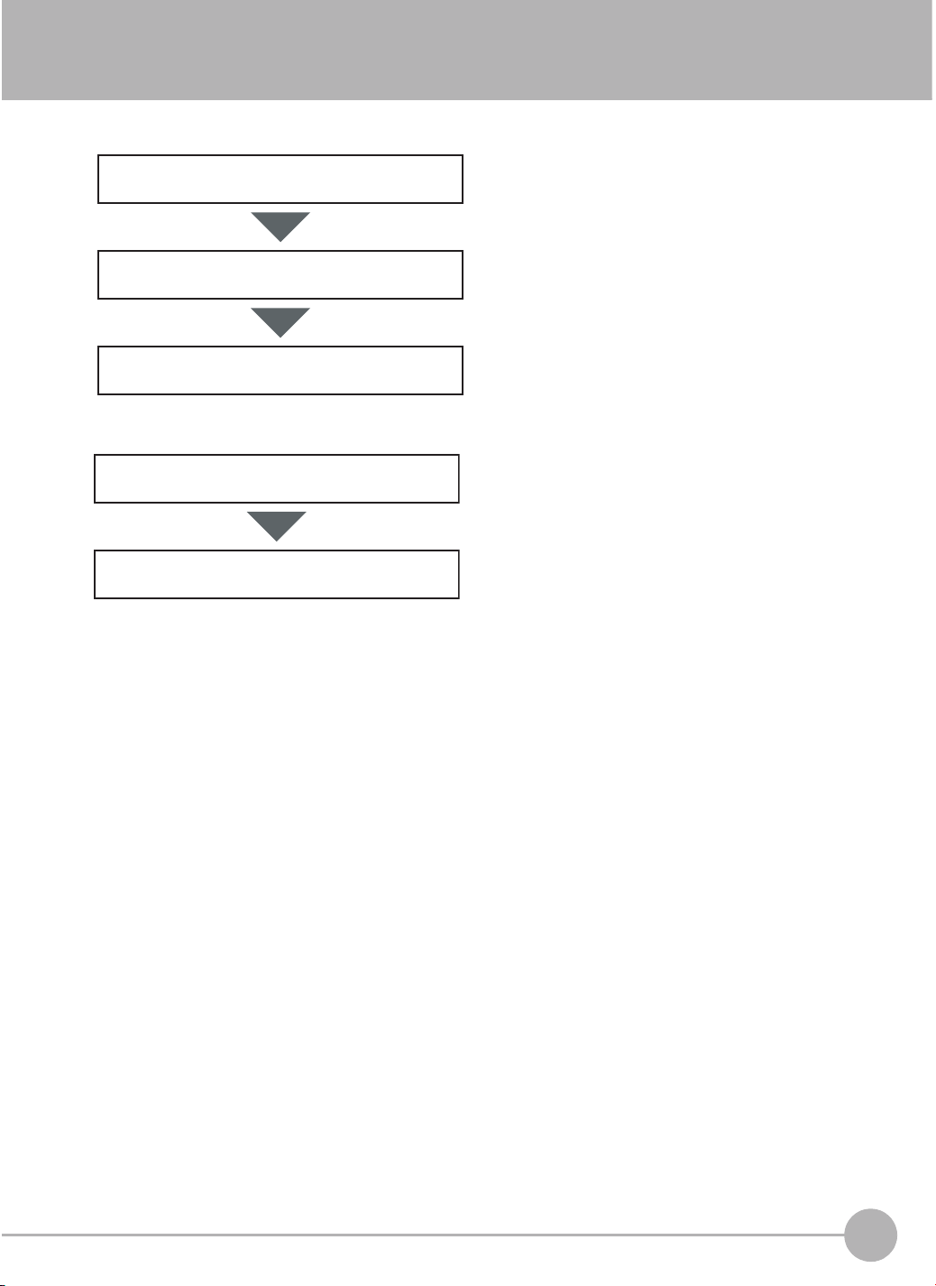
4-2 Setup Procedure for Inspection Items
The basic steps for setting up inspection items are shown below.
Step 1
Step 2
Step 3
If measurements are unstable
Step 4
Step 5
Configuring Inspection Items
Teaching
Setting Judgement Parameters
Setting Detailed Items
Re-teaching
4
Setting Up Inspections
FQ2-S4 User’s Manual
Setup Procedure for Inspection Items
93
Page 96

4-3 Configuring Inspection Items
Adding New Inspection Items
1 Press [Inspect] − [Inspection].
2 Press an unused inspection item number.
3 Press [Add item.] on the menu.
4 Select an inspection item, such as [Search].
When registering multiple inspection items, press the
inspection item number after 1.--- and set it in the
same way.
Note
If more than seven inspection items are set, drag the icon at the bottom of the menu upward to display the next
inspection item numbers.
94
Configuring Inspection Items
FQ2-S4 User’s Manual
Page 97

Modifying Existing Inspection Items
Press the number of the inspection item to be set.
1
2 Press [Modify] on the menu.
Deleting Inspection Items
4
Setting Up Inspections
1 Press the number of the inspection item to be delet-
ed.
2 Press [Delete] on the menu.
Note
Executing Similar Measurements in Different Places
→ Copy an inspection item that is already registered: [Copy].
→ Change the name of an inspection item: [Rename].
FQ2-S4 User’s Manual
Configuring Inspection Items
95
Page 98

4-4 Reading and Verifying Character Strings
Character String Recognition
Character recognition is used to read characters in input images as character information based on font
information that is registered in the Sensor in advance. The characters that were read can be output to an
external device. You can also verify the character string that was read to see if it matches a character string that
was registered in advance or the read result from a Bar Code, 2D-code, or 2D-code (DPM) inspection item that
was executed before the current inspection item.
Measurement region
12.10.1
PQD/CE6800
Range in which characters can be read
Vertical: 4 lines max.
Horizontal: 32 characters max.
Characters That Can Be Recognized
Item Description
*1
Numbers
*1
Letters
*1
Symbols
*1 Any symbols other than those that are listed above cannot be recognized.
*2 Normally only uppercase letters can be recognized. Lowercase letters can be recognized if model dictionaries are
used. Each lowercase letter must be registered individually.
Model Dictionaries: p. 105
Note
User fonts can be registered separately to enable recognition.
0 to 9
*2
A to Z
‘ (apostrophe)
- (hyphen)
. (period)
: (colon)
/ (slash)
Dictionary File Registration: p. 105
96
Reading and Verifying Character Strings
FQ2-S4 User’s Manual
Page 99

Setup Procedure for Character Recognition
The setup for character recognition is performed in the following order.
The basic settings to recognize characters are made.
Teaching
Judgement conditions
Verification conditions
• Character format (number of characters, alphanumeric
characters or symbols, etc.)
• Measurement region
• Detailed parameters to recognize characters (These
are set automatically.)
Settings are made to check whether the characters that
were read from the workpiece were recognized correctly.
Differences between the references that were taught for
character recognition and the actual result of reading the
characters are detected and conditions are set to determine how accurately characters are read.
You can set conditions to verify that the character string
that was read matches a specific character string. The
character strings to use to verify the character strings
that are read are registered in the master data.
Setup Procedure for Character Recognition
4
Setting Up Inspections
Step 1 Selecting the Inspection Item
[Inspect] − [Inspection]
1 Press an unused inspection item number and press
[Add item.].
2 Press [OCR].
Registering inspection items: p. 94
Note
Drag the arrow ( ) at the bottom of the menu to display all of
the inspection items.
FQ2-S4 User’s Manual
Reading and Verifying Character Strings
97
Page 100

Step 2 Teaching
For teaching, you specify the measurement region and the format of the characters to read (number of characters,
alphanumeric characters or symbols, etc.). Detailed parameters to recognize the characters will be set automatically.
Also, you can register the characters that are actually read when teaching as a verification condition in the master
data.
Step 4 Setting the Verification Conditions
1 Press [TEACH].
2 Place the characters to read in front of the camera.
3 Move the rectangle around the character string to
read, and then press [OK].
The measurement region will be set.
4 The characters that were read with the initial param-
eters will be displayed above each line.
You set the format of the characters to recognize to prevent reading similar characters incorrectly. (This display
will not appear if the character format is already registered.)
• Number of characters to read in the character string
• Types of characters (letters, numbers, symbols, fixed
*2
characters,
etc.)
Enter the types of characters in order and the number of
characters according to the actual character string that
was read.
*1
Example
2012.12.20 → Line 1 ####.##.##
FQ-OCR Line 2 ??-???
*1 If the number of characters that were actually read is less than the number of characters that was specified in the
character format, it is assumed that reading the characters failed.
*2 If alphanumeric characters are directly specified as fixed characters but the characters that were read do not
match the specified characters, it is assumed that reading the characters failed.
The following table gives detailed specifications for the character format.
Item Description
Characters that can be
entered in the character format string
98
Reading and Verifying Character Strings
• Numbers
0 to 9
• Letters
A to Z
• Symbols
‘ (apostrophe), - (hyphen), . (period), : (colon), / (slash), wildcard
Wildcards
You can use wildcards to specify characters. For example, you can use wildcards to prevent incorrect recognition of 0 (zero) and O (the letter O).
?: Any character (recognized characters: any characters except for symbols)
#: Any number from 0 to 9 (recognized characters: 0 to 9)
$: Any letter from A to Z (recognized characters: A to Z)
@: Any symbol (recognized characters: ‘ - . : / )
*: Skip (No judgement is made for the judgement conditions (similarity or stability). The detected character
count is also not incremented.)
FQ2-S4 User’s Manual
 Loading...