

Page 1
Smart Camera
FQ2-S/CH Series
User's Manual
for Communications Settings
Cat. No. Z338-E1-02
Page 2

Introduction
Thank you for purchasing the FQ2-S/CH.
This manual provides information regarding functions, performance and operating methods that
are required for using the FQ2-S/CH.
When using the FQ2-S/CH, be sure to observe the following:
• The FQ2-S/CH must be operated by personnel knowledgeable in electrical engineering.
• To ensure correct use, please read this manual thoroughly to deepen your understanding of the
product.
• Please keep this manual in a safe place so that it can be referred to whenever necessary.
Page 3

APPLICATION CONSIDERATIONS
(Please Read)
User's Manual for
Communications Settings
Overview of Communication Specifications
Controlling Operation and Outputting
Data with a Parallel Connection
Controlling Operation and Outputting
Data with an Ethernet Connection
Controlling Operation and Outputting
Data with an RS-232C Connection
Appendices
1
2
3
4
5
Smart Camera
FQ2-S/CH
Page 4
Product manuals
Important
Note
2-2 Par
FQ2-CH1
FQ2-S1 FQ2-S2 FQ2-S3
Shows the models that support the function being described.
Shows that the FQ2-S1 supports the function.
Shows that the FQ2-S2 supports the function.
Shows that the FQ2-S3 supports the function.
Shows that the FQ2-S4 supports the function.
Shows that the FQ2-CH supports the function.
FQ2-CH
FQ2-S4
FQ2-S3
FQ2-S2
FQ2-S1
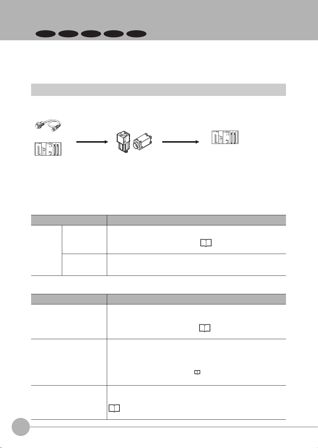
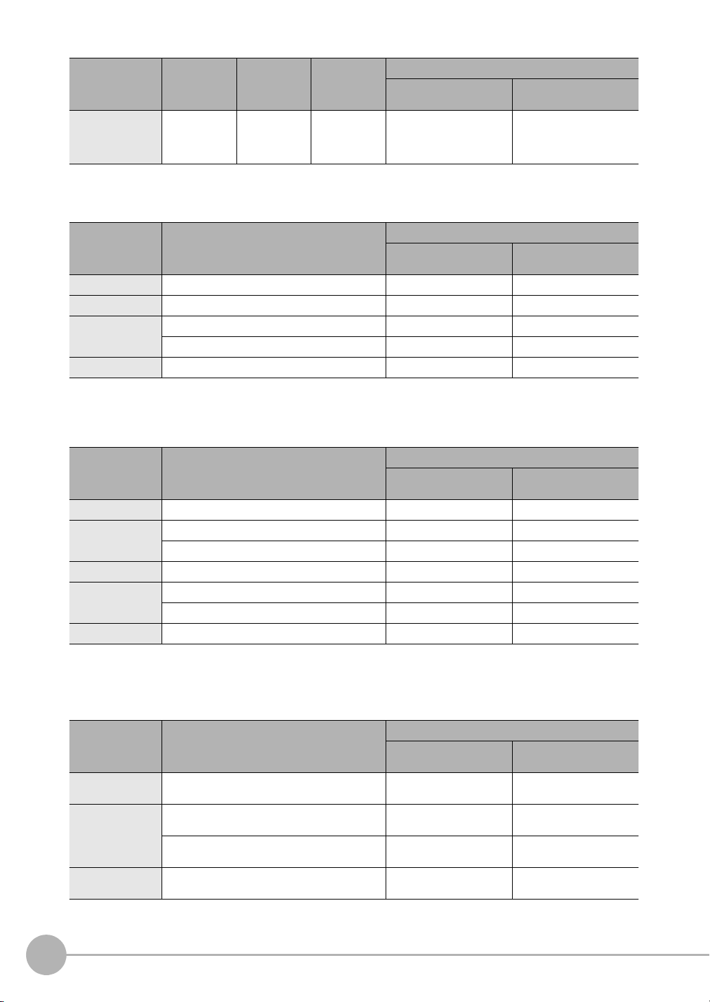
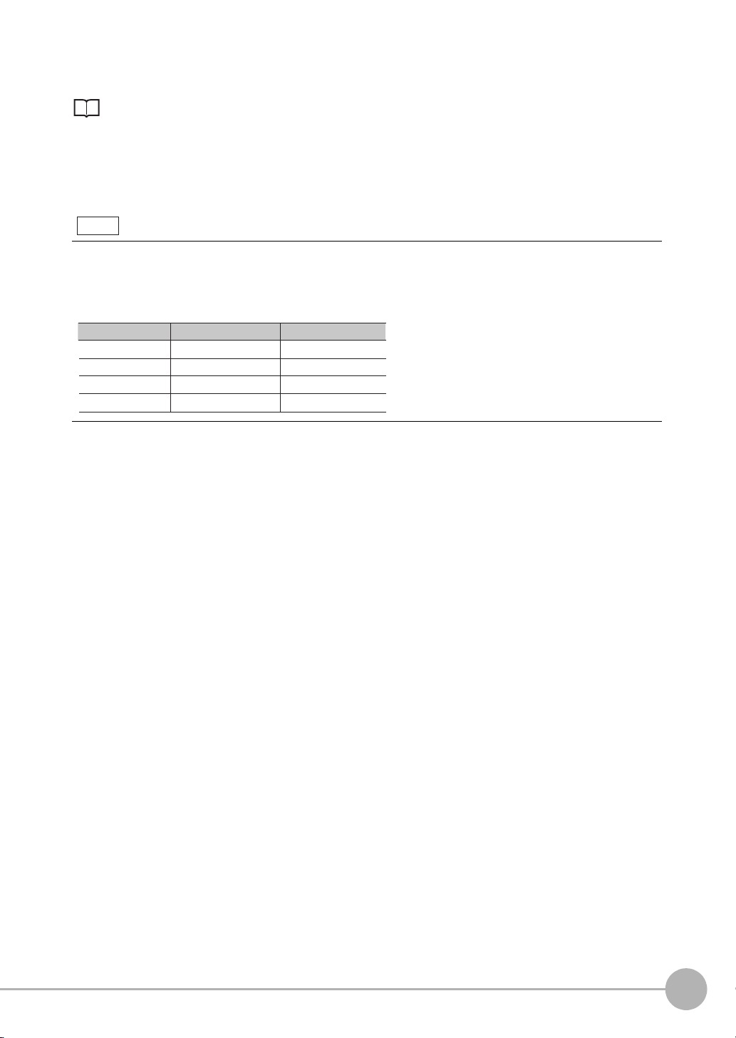
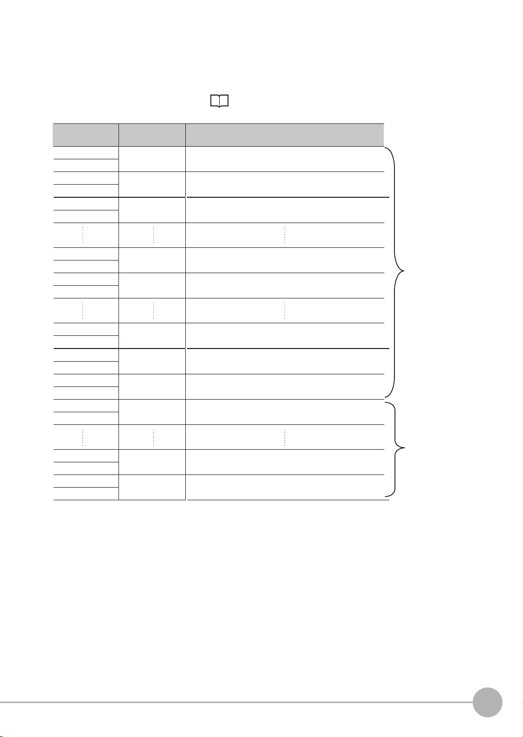
The information required to use the FQ2-S/CH Series is divided into two manuals by objective: “FQ2-S/CH
Series User’s Manual” and “FQ2-S/CH Series User's Manual for Communications Settings”. Read each
manual as appropriate for your objective.
Manual Description Contents
FQ2-S/CH Series User's Manual
(Cat. No. Z337)
(This manual) FQ2-S/CH Series
User's Manual for Communications
Settings (Cat. No. Z338)
Describes the product specifications,
basic settings, and other information
required to use the FQ2-S/CH Series.
Provides information required to operate the sensor by remote control.
Product specifications
Connections, wiring
Camera, image adjustment
Inspection item settings
Test measurement, operation
Troubleshooting
System configuration
Sensor control method
Data input/output specifications
Connectable network types
Communication settings
Output data settings
Editor's Note
■ Meaning of Symbols
Menu items that are displayed on the Touch Finder LCD screen, and windows, dialog boxes and other GUI
elements displayed on the PC are indicated enclosed by brackets "[ ]".
■ Visual Aids
Indicates points that are important to achieve the full product performance,
such as operational precautions.
2
Indicates application procedures.
Indicates pages where related information can be found.
FQ2-S/CH User’s Manual
for Communications Settings
Page 5

Table of Contents
1. Overview of Communication Specifications
1-1 Confirming the System Configuration . . . . . . . . . . . . . . . . . . . . . . . . . . . . 8
FQ2-S/CH Series System Configuration . . . . . . . . . . . . . . . . . . . . . . . . . . . . . . . 8
1-2 Communicating with an External Device . . . . . . . . . . . . . . . . . . . . . . . . . 10
Basic Control Operations of the Sensor . . . . . . . . . . . . . . . . . . . . . . . . . . . . . . 10
Control Methods for the Sensor . . . . . . . . . . . . . . . . . . . . . . . . . . . . . . . . . . . . 11
Communication Protocols for Communication with the Sensor . . . . . . . . . . . .12
1-3 Control Methods Using an External Device . . . . . . . . . . . . . . . . . . . . . . . 18
Control with Control Signals and Status Signals . . . . . . . . . . . . . . . . . . . . . . . . 18
Command/Response Method . . . . . . . . . . . . . . . . . . . . . . . . . . . . . . . . . . . . . . 20
Data Output after Measurements . . . . . . . . . . . . . . . . . . . . . . . . . . . . . . . . . . . 21
2. Controlling Operation and Outputting Data with a Parallel Connection
2-1 Controlling Operation and Outputting Data
with the Sensor's Standard Parallel Connection . . . . . . . . . . . . . . . . . . . 34
Basic Operation with a Parallel Connection . . . . . . . . . . . . . . . . . . . . . . . . . . . 34
Setting the Measurement Trigger . . . . . . . . . . . . . . . . . . . . . . . . . . . . . . . . . . . 36
Setting the Outputs . . . . . . . . . . . . . . . . . . . . . . . . . . . . . . . . . . . . . . . . . . . . . . 40
Controlling the Sensor from an External Device . . . . . . . . . . . . . . . . . . . . . . . . 46
2-2 Controlling Operation and Outputting Data
with a Parallel Interface Sensor Data Unit . . . . . . . . . . . . . . . . . . . . . . . . 60
Overview . . . . . . . . . . . . . . . . . . . . . . . . . . . . . . . . . . . . . . . . . . . . . . . . . . . . . . 60
Setting the Measurement Trigger . . . . . . . . . . . . . . . . . . . . . . . . . . . . . . . . . . . 60
Setting Output Data . . . . . . . . . . . . . . . . . . . . . . . . . . . . . . . . . . . . . . . . . . . . . . 61
Aligning the Data Output Timing with the External Device . . . . . . . . . . . . . . . . 66
Changing the Settings of the I/O Signals . . . . . . . . . . . . . . . . . . . . . . . . . . . . . 74
Controlling Operation from an External Device . . . . . . . . . . . . . . . . . . . . . . . . . 75
Table of Contents
FQ2-S/CH User’s Manual
for Communications Settings
3
Page 6

3. Controlling Operation and Outputting Data with an Ethernet Connection
3-1 Controlling Operation and Outputting Data
with EtherNet/IP Communications. . . . . . . . . . . . . . . . . . . . . . . . . . . . . . . 88
Introduction to EtherNet/IP . . . . . . . . . . . . . . . . . . . . . . . . . . . . . . . . . . . . . . . .88
FQ2 Communications for EtherNet/IP Connections . . . . . . . . . . . . . . . . . . . . . 90
Setting Up EtherNet/IP Communications . . . . . . . . . . . . . . . . . . . . . . . . . . . . . 92
Tag Data Link Setting Methods . . . . . . . . . . . . . . . . . . . . . . . . . . . . . . . . . . . . .95
Setting the Data to Output Automatically after Measurements . . . . . . . . . . . . . 97
Memory Assignments and Commands . . . . . . . . . . . . . . . . . . . . . . . . . . . . . . 102
Timing Chart for EtherNet/IP Communications . . . . . . . . . . . . . . . . . . . . . . . . 114
Sample Ladder Programming . . . . . . . . . . . . . . . . . . . . . . . . . . . . . . . . . . . . . 119
Communicating with the Sensor Controller
with EtherNet/IP Message Communications . . . . . . . . . . . . . . . . . . . . . . . . . . 120
Command Setting Example . . . . . . . . . . . . . . . . . . . . . . . . . . . . . . . . . . . . . . . 120
3-2 Controlling Operation and Outputting Data
with PLC Link Communications . . . . . . . . . . . . . . . . . . . . . . . . . . . . . . . 121
Communications Processing Flow . . . . . . . . . . . . . . . . . . . . . . . . . . . . . . . . . 121
Setting Up PLC Link Communications . . . . . . . . . . . . . . . . . . . . . . . . . . . . . . 122
Setting the Data to Output Automatically after Measurements . . . . . . . . . . . . 124
Memory Assignments for PLC Link Communications . . . . . . . . . . . . . . . . . . . 129
Timing Chart for PLC Link Communications . . . . . . . . . . . . . . . . . . . . . . . . . . 137
Sample Ladder Programming . . . . . . . . . . . . . . . . . . . . . . . . . . . . . . . . . . . . . 139
3-3 Outputting Data and Controlling Operation through PROFINET . . . . . 140
Overview of PROFINET . . . . . . . . . . . . . . . . . . . . . . . . . . . . . . . . . . . . . . . . . 140
FQ2 Communications for PROFINET Connections . . . . . . . . . . . . . . . . . . . . 144
Setting Up EtherNet/IP Communications (PROFINET) . . . . . . . . . . . . . . . . . . 145
Communication Settings Procedure . . . . . . . . . . . . . . . . . . . . . . . . . . . . . . . . 147
Setting the Data to Output Automatically after Measurements . . . . . . . . . . . . 148
Memory Assignments and Commands . . . . . . . . . . . . . . . . . . . . . . . . . . . . . . 152
Timing Chart for EtherNet/IP Communications . . . . . . . . . . . . . . . . . . . . . . . . 161
Sample Ladder Programming . . . . . . . . . . . . . . . . . . . . . . . . . . . . . . . . . . . . . 165
3-4 Control and Output in No-Protocol (TCP) / No-Protocol (UDP) . . . . . . 167
Communications Processing Flow . . . . . . . . . . . . . . . . . . . . . . . . . . . . . . . . . 167
Setting Up No-protocol Communications . . . . . . . . . . . . . . . . . . . . . . . . . . . . 167
Setting the Data to Output Automatically after Measurements . . . . . . . . . . . . 169
Controlling the Sensor from an External Device
(Procedure for No-protocol Command/Response Communications) . . . . . . .176
Binary Data File Load and Save Commands . . . . . . . . . . . . . . . . . . . . . . . . . 183
4
FQ2-S/CH User’s Manual
for Communications Settings
Page 7

3-5 Controlling Operation and Outputting Data
with FINS/TCP No-protocol Commands . . . . . . . . . . . . . . . . . . . . . . . . . 188
Introduction to FINS Commands . . . . . . . . . . . . . . . . . . . . . . . . . . . . . . . . . . .188
Setting Up FINS/TCP No-protocol Communications . . . . . . . . . . . . . . . . . . . . 189
List of FINS Commands . . . . . . . . . . . . . . . . . . . . . . . . . . . . . . . . . . . . . . . . . 190
4. Controlling Operation and Outputting Data with an RS-232C Connection
4-1 Introduction to RS-232C Connections . . . . . . . . . . . . . . . . . . . . . . . . . . 196
4-2 Controlling Operation and Outputting Data
with RS-232C No-protocol Communications . . . . . . . . . . . . . . . . . . . . . 197
Communications Processing Flow . . . . . . . . . . . . . . . . . . . . . . . . . . . . . . . . . 197
Setting Up No-protocol Communications . . . . . . . . . . . . . . . . . . . . . . . . . . . . 197
Setting the Data to Output Automatically after Measurements . . . . . . . . . . . . 198
Controlling the Sensor from an External Device
(Procedure for No-protocol Command/Response Communications) . . . . . . .198
5. Appendices
5-1 Command Control. . . . . . . . . . . . . . . . . . . . . . . . . . . . . . . . . . . . . . . . . . . 200
Parameter Notation Examples for Command Control . . . . . . . . . . . . . . . . . . . 200
Command List . . . . . . . . . . . . . . . . . . . . . . . . . . . . . . . . . . . . . . . . . . . . . . . . . 202
Command Details . . . . . . . . . . . . . . . . . . . . . . . . . . . . . . . . . . . . . . . . . . . . . . 207
5-2 Detailed EtherNet/IP Communications Specifications . . . . . . . . . . . . . 433
Index. . . . . . . . . . . . . . . . . . . . . . . . . . . . . . . . . . . . . . . . . . . . . . . . . . . . . . . . . . 438
Revision History . . . . . . . . . . . . . . . . . . . . . . . . . . . . . . . . . . . . . . . . . . . . . . . . 440
FQ2-S/CH User’s Manual
for Communications Settings
5
Page 8

6
FQ2-S/CH User’s Manual
for Communications Settings
Page 9

1
Overview of Communication Specifications
Overview of Communication Specifications
1-1 Confirming the System Configuration . . . . . . . . . . . . . . . . . . . . . . . . . .8
1-2 Communicating with an External Device . . . . . . . . . . . . . . . . . . . . . . . 10
1-3 Control Methods Using an External Device . . . . . . . . . . . . . . . . . . . . . 18
Page 10
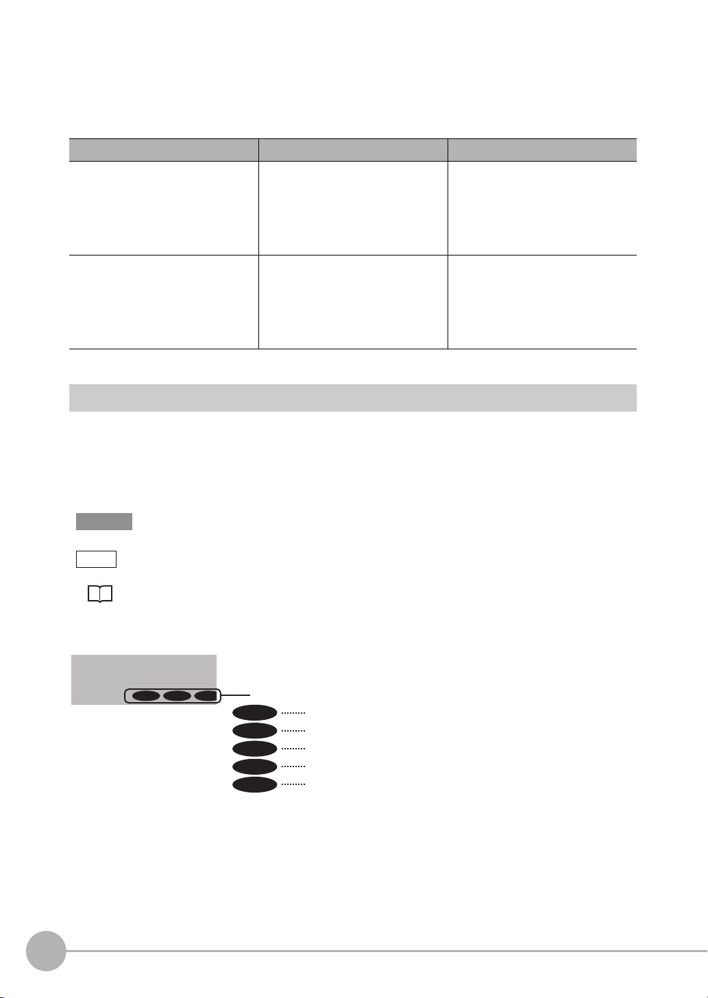
1-1 Confirming the System Configuration
FQ2-S1
FQ2-S2
FQ2-CH
Parallel Interface Connection
Sensor Data
Unit cable
Parallel Interface
Sensor Data Unit
I/O cable
Basic configuration External devices
Setup Tool
(Touch Finder or PC Tool)
Special Ethernet Cable
(RJ45/M12)
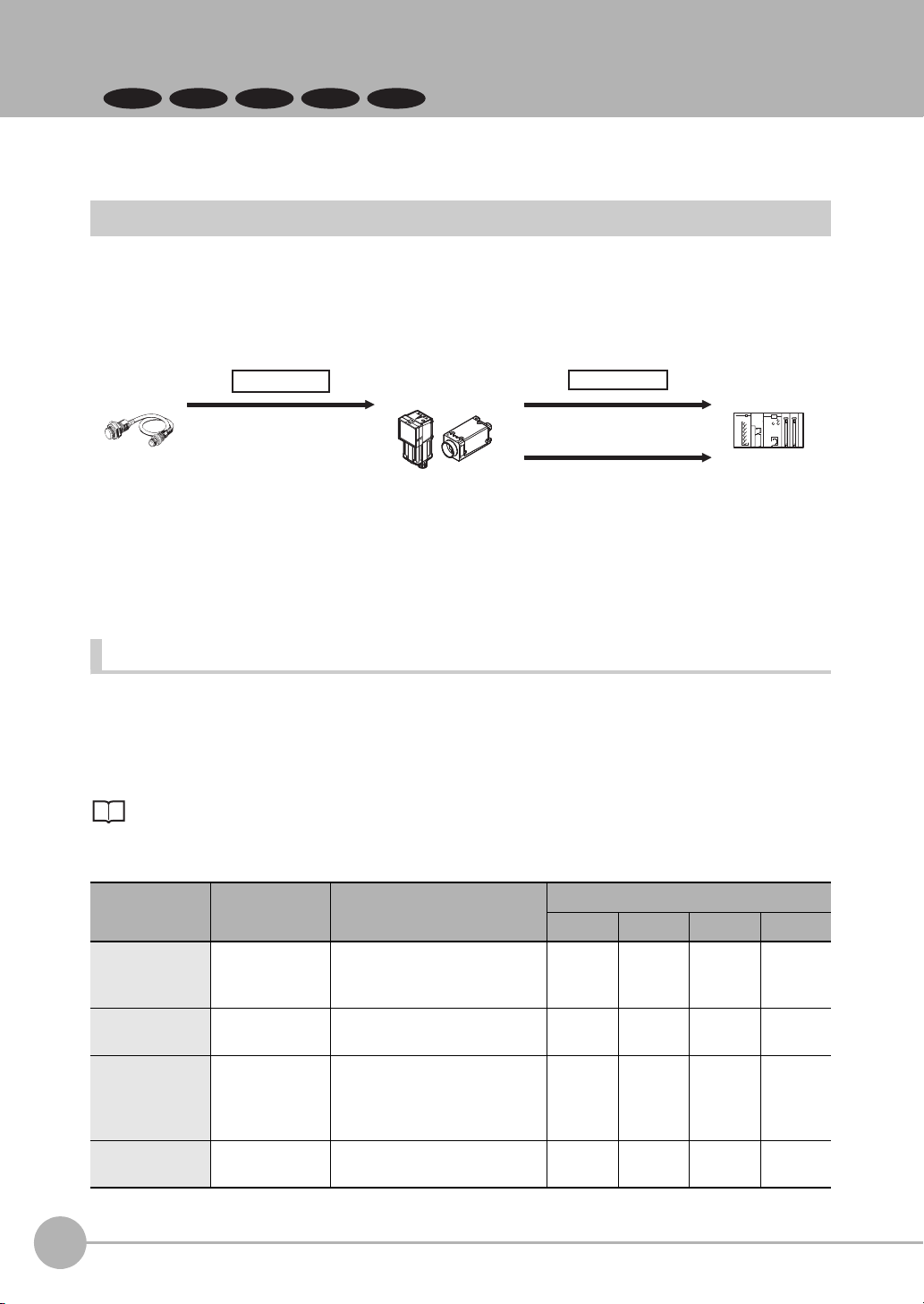
Connection with Standard Parallel Interface of the Vision Sensor
I/O control PLC
I/O cable
Basic configuration
FQ2-S/CH Series
FQ2-S/CH Series
External devices
Trigger sensor
I/O control PLC
Trigger sensor
Setup Tool
(Touch Finder or PC Tool)
Special Ethernet Cable
(RJ45/M12)
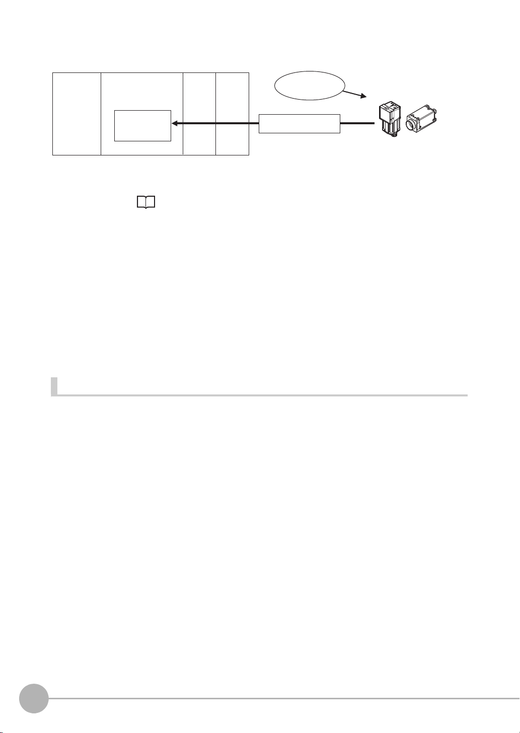
A Parallel Interface Sensor Data Unit can be installed to enable output of measured values,
parameters, calculation results, and other information.
Use an I/O cable for input of measurement triggers and communication commands,
and for output of OK/NG judgement results.
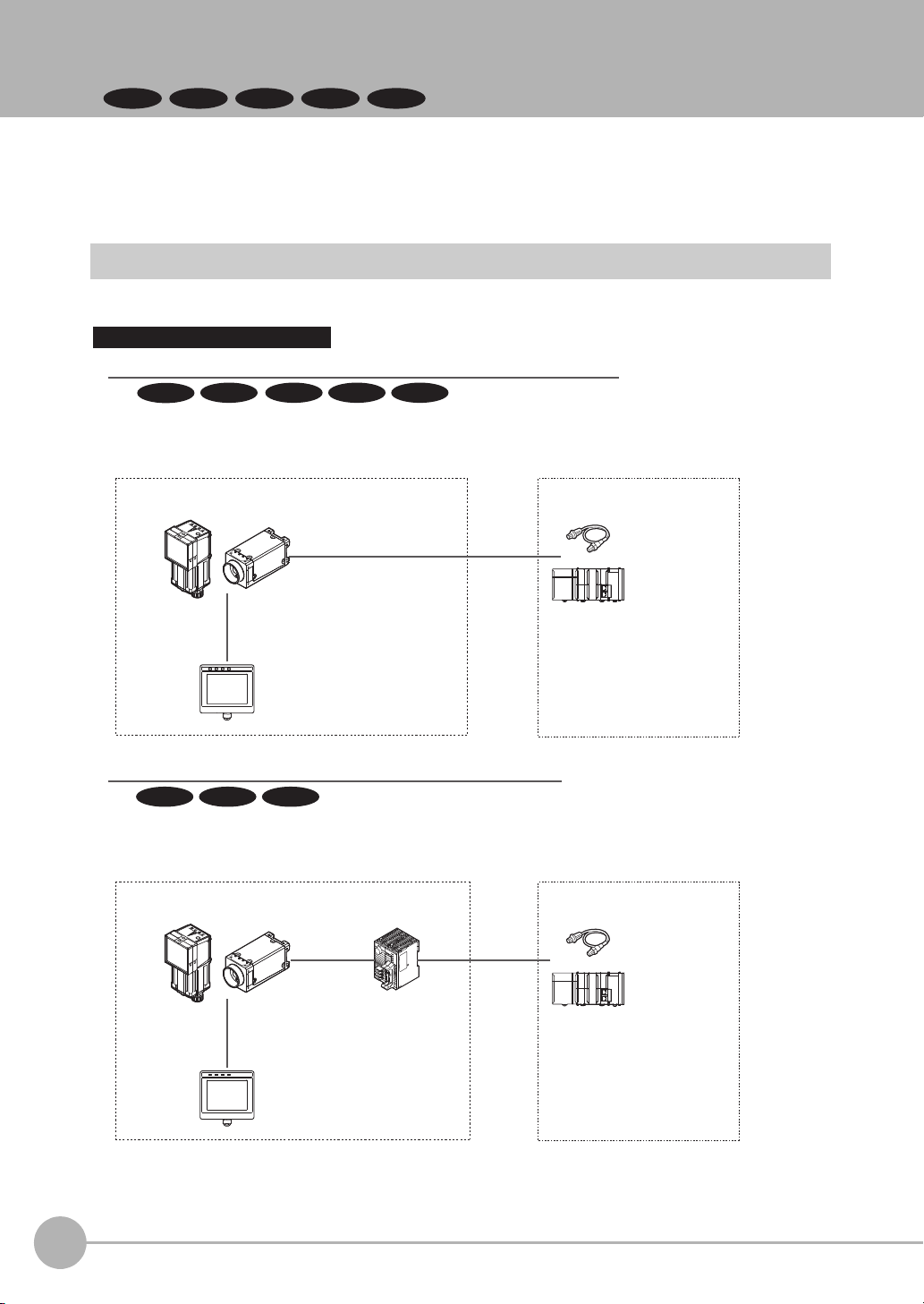
Connection through a Parallel Interface Sensor Data Unit
FQ2-S1
FQ2-S3 FQ2-S4 FQ2-CH
FQ2-S3 FQ2-S4 FQ2-CH
FQ2-S2
FQ2-S3 FQ2-S4
The FQ2-S/CH series is Vision System that perform measurement processing through measurement objects
that are imaged by a Camera.
In a system configuration that is connected to a PLC, computer, or other external device, measurement
commands can be received from and measurement results can be output to the external device.
FQ2-S/CH Series System Configuration
The following types of system configurations can be used with the FQ2.
8
Confirming the System Configuration
FQ2-S/CH User’s Manual
for Communications Settings
Page 11
Ethernet (EtherNet/IP, PLC Link, No-protocol, or PROFINET) Connection
Basic configuration External devices
I/O control PLC
Trigger sensor
Setup Tool
(Touch Finder
or PC Tool)
General-purpose Ethernet cable
Switching hub for
EtherNet/IP
(industrial Ethernet)
FQ2-S/CH Series
FQ2-S/CH Series
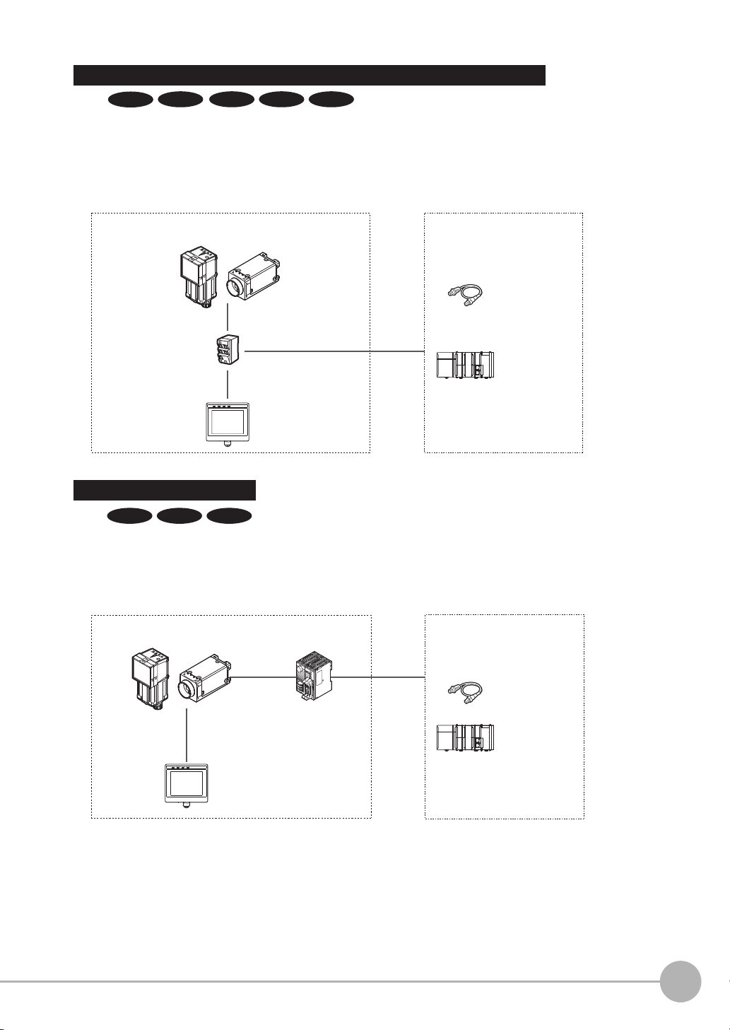
RS-232C Serial Connection
RS-232C
cable
RS-232C Interface
Sensor Data Unit
*2
Sensor Data
Unit cable
Basic configuration External devices
Sensor control PLC
I/O control PLC
Trigger sensor
Setup Tool
(Touch Finder or PC Tool)
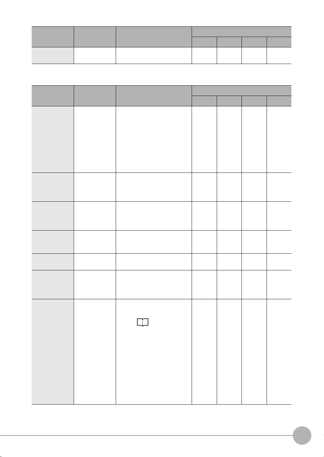
An RS-232C Interface Sensor Data Unit can be connected to the Sensor by RS-232C cable to
enable input of measurement triggers and communication commands, and output of measurement
results (judgement results, measured values). Measurement triggers can also be input from a parallel
connection.
Ethernet cable can be used to connect to a variety of networks in order to input measurement
triggers and communication commands, and to output measurement results (judgement results,
measured values). Measurement triggers can also be input from a parallel connection. The data
link function for each network (excluding no-protocol networks) can be used to periodically
transfer data between the sensor and external devices.
Special Ethernet Cable
(RJ45/M12)
*1
General-purpose Ethernet cable
*1: A special Ethernet cable is used to connect to the sensor.
*2: A parallel cable (FQ-SDU2 special-purpose cable) can be used to connect to external devices from the Sensor Data Unit.
In this case, an ACK signal can be used as an additional output signal.
Special Ethernet Cable
(RJ45/M12)
FQ2-S1
FQ2-S3 FQ2-S4 FQ2-CHFQ2-S2
FQ2-S3 FQ2-S4 FQ2-CH
1
Overview of Communication Specifications
FQ2-S/CH User’s Manual
for Communications Settings
Confirming the System Configuration
9
Page 12
1-2 Communicating with an External Device
FQ2-S1
FQ2-S2
FQ2-CH
Trigger sensor
PLC
PLC
The measurement
results are output.
• Status signals
• Overall judgement
• Measured values
• Character strings
Measurement
triggers and other
control commands
are input.
Sensor
FQ2-S3 FQ2-S4
This section gives the communications specifications, describes the control methods that you can use for
communications, and describes the settings that are required before starting communications with an external
device.
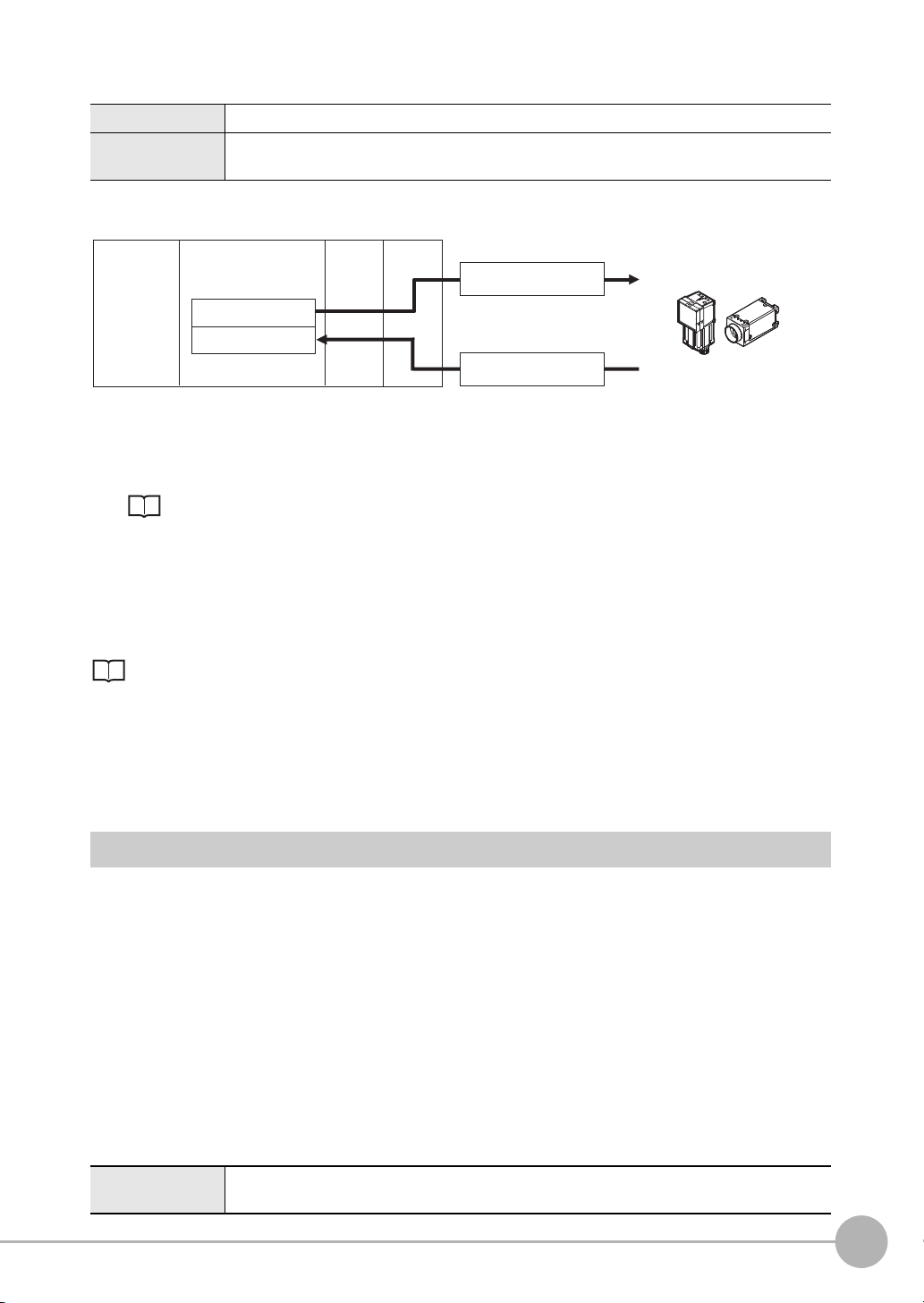
Basic Control Operations of the Sensor
The following figure shows basic communications between an external device and the Sensor and the flow of
signals and data.
The following methods can be used to exchange data between an external device and the Sensor.
10
Commands That Can Be Input to the Sensor from an External Device
Ty p e Description
Control commands
Control signals
(input signals)
Communications
command input
A measurement is executed when a measurement trigger (i.e., an ON TRIG signal) is input.
For information on control signals, refer to Control with Control Signals and
Status Signals: p.18.
Various commands can be executed, such as measuring commands and scene
change. The communications commands depend on the communications protocol that you use. Refer to the section for each communications protocol for details.
Data Output to an External Device from the Sensor
Ty p e Description
Status signals When the Sensor confirms a control signal or communications command input
and begins measurement processing, the status of the Sensor is reported to the
external device through status signals (e.g., a BUSY signal).
For information on status signals, refer to Control with Control Signals and
Status Signals: p.18.
Overall judgement NG is output whenever there is one or more NGs in the judgement results for mul-
Measured values The measured values from inspection items can be output. The output items must
Communicating with an External Device
tiple inspection items.
The overall judgement can be output through the OR signal or through the JG output parameter.
*1: This behavior can be changed in the settings.
For information on the OR signal, refer to Control with Control Signals and Status Signals: p.18.
For information on the JG output parameter.
be inspection items for output and registered as output data (data 0 to data 31).
Refer to the following for details.
Settings Required for Data Output: p.61, 97, 124, 148, 169, 198.
You can also use commands to obtain results after a measurement is performed.
*1
FQ2-S/CH User’s Manual
for Communications Settings
Page 13

Ty p e Description
Trigger sensor
External device
Status signal
Control signal
Sensor
Character output (FQ2-S4/CH
series only)
You can output character strings and numbers that are read by inspection items
such as OCR, Barcode, 2D-code, or 2D-code (DPM). Refer to Items That
Can Be Output as Output Data: p.22 for details.
You can also use commands to obtain results after a measurement is performed.
1
Control Methods for the Sensor
There are three methods that you can use to control the Sensor from a PLC or other external device. They are
described in this section.
For details on each control method, refer to their corresponding section.
Control Methods
Method Overview Trigger type or area Signals or area used
Control signals and
status signals
Control with commands and
responses
Data output after
measurements
Operation is controlled by the
ON/OFF status of the Measurement Trigger Signal
(TRIG) and Command
Request Bit (EXE).
Control is performed by sending control commands. The
execution results of the command can be confirmed in the
response from the Sensor.
After a measurement is performed, the previously specified measurement data is
output automatically.
ON/OFF status of the control
signals and status signals
The control command code is
stored in the I/O memory of
the PLC and then the Request
Bit is turned ON.
Not required. (Output is performed automatically after
measurement.)
Control signals and status signals
PLC I/O memory (Command
Area and Response Area)
PLC I/O memory (Data Output Area)
1 Control with Control Signals and Status Signals (Refer to Control with Control Signals and
Status Signals: p.18)
Control and status confirmation for the Sensor is performed with the ON/OFF status of the control and
status signals.
This method is best suited for basic operations such as measurement triggers or to check the operating
status of the Sensor.
Overview of Communication Specifications
FQ2-S/CH User’s Manual
for Communications Settings
Communicating with an External Device
11
Page 14
2 Command/Response Method (Refer to Command/Response Method: p.20)
External device
I/O memory
Sensor
Command Area
Response Area
(1) Command
(3) Response
Output Area
(2) Command
execution
External device
I/O memory
Sensor
Command Area
Response Area
(2) Measurement data
Output Area
(1) Measurement processing
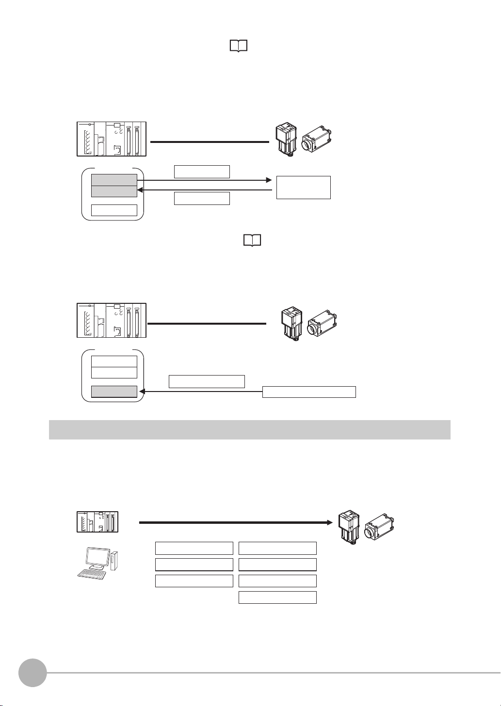
Control is performed by storing the control command and the response to that command in the I/O memory of a PLC.
This method is best suited to send multiple commands to the Sensor without using PLC communications
instructions.
3 Data Output after Measurements (Refer to Data Output after Measurements: p.21)
After a measurement is executed, the measurement data specified for output is automatically output to
the specified words in the I/O memory of the PLC.
This is suited to reception of the measurement result data of each inspection item.
The Sensor can be controlled from a PLC, computer, or other external device using a variety of communication
protocols.
The communication protocols that can be used to control the Sensor from an external device are described
below.
12
Communicating with an External Device
Communication Protocols for Communication with the Sensor
PLC
Computer
Control can be performed through different communications protocols.
Parallel
PLC Link
No-protocol (TCP)
EtherNet/IP
PROFINET
No-protocol (UDP)
No-protocol (FINS/TCP)
Sensor
FQ2-S/CH User’s Manual
for Communications Settings
Page 15

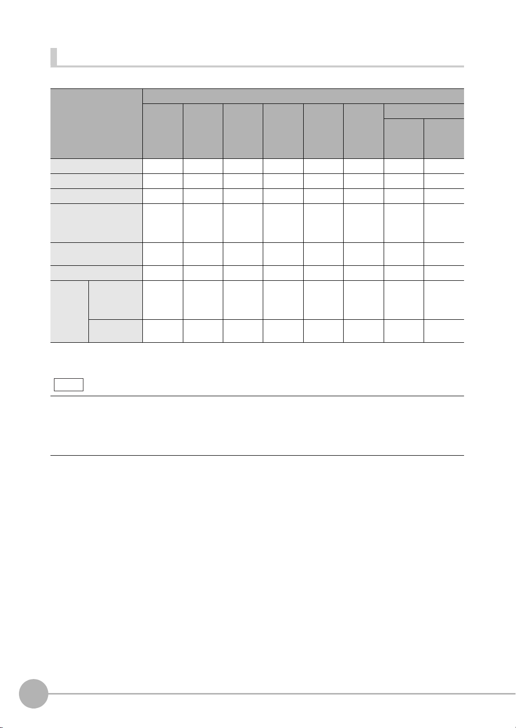
Applicable Communications Protocols
The communication protocols of each communication method that can be used with the Sensor are as follows:
OK: Supported, ---: Not supported.
Communications
method
Contact
inputs
Data sharing
Frame
transmission
*1: When connected to a CJ-series PLC, specify the areas in the I/O memory.
*2: This connection is via the RS-232C Interface Sensor Data Unit. Only supported on the FQ2-S3/S4/CH series.
Communi-
Overview Communications cable type
cations
protocol
Parallel Data is exchanged between an external device and the
Sensor through combinations of ON/OFF signals from
multiple physical contacts.
PLC Link This is OMRON’s communications protocol for Vision
System.
The control signals, Command Area/Response Area,
and area to store measurement data are assigned in
the I/O memory of the PLC, and data is exchanged
cyclically to share data between the PLC and the Vision
System.
EtherNet/IP This is an open communications protocol.
Tag data links are used for communication with the Sen-
sor.
On the PLC, structure variables are created that corre-
spond to the control signals, command/response data,
and measurement data. These variables are then used
as tags to input and output data through tag data links
to exchange data between the PLC and the Sensor.
PROFINET This is an open communications protocol.
RT (Real-time) of soft real-time communication (SRT) is
used for communication with the Sensor.
The control signals, Command Area/Response Area,
and area to store measurement data are assigned in
the I/O memory of the PLC, and data is exchanged
cyclically to share data between the PLC and the Vision
System.
No-protocol (TCP)
No-protocol (UDP)
No-protocol (FINS/
TCP)
Command frames are sent to the Sensor and response
frames are received from the Sensor without the use of
any specific protocol.
Data can be exchanged between the PLC, computer, or
other external device and the Sensor by sending and
receiving ASCII or binary format data.
This is a command system (FINS) for message services
that can be used in common on OMRON networks.
Data can be exchanged between an OMRON PLC and
the Sensor by a command/response method.
*1
Parallel
I/O
OK --- OK
--- OK ---
--- OK ---
--- OK ---
--- OK ---
--- OK ---
Ethernet RS-232C
*2
1
Overview of Communication Specifications
FQ2-S/CH User’s Manual
for Communications Settings
Communicating with an External Device
13
Page 16
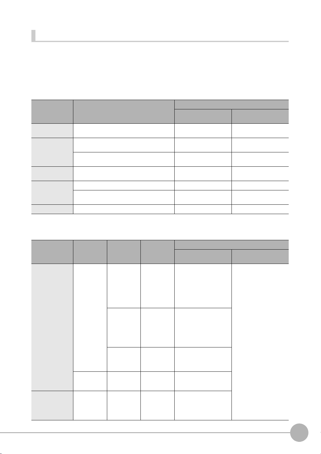
Connection Compatibility
Note
Yes: Supported, No: Not supported
Type of connection to
FQ2-S/CH
EtherNet/IP --- No No Yes Yes Yes Yes Yes
PLC Link on Ethernet No --- No Yes Yes Yes Yes Yes
PROFINET No No --- Yes Yes Yes Yes Yes
TCP no-protocol communications on Ethernet,
UDP no-protocol communications on Ethernet
FINS/TCP no-protocol communications on Ethernet
RS-232C
Parallel
communications
*1: This applies when an RS-232C Interface Sensor Data Unit is connected.
*2: This applies when a Parallel Interface Sensor Data Unit is connected.
*1
Sensor’s standard parallel
communications
Parallel Inter-
*2
face
Other connection
EtherNet/IP PLC Link
Yes Yes Yes --- No No Yes Yes
YesYesYesNo --- No YesYes
YesYesYesNo No --- YesNo
YesYesYesYesYesYes--- No
YesYesYesYesYesNo No ---
on Ethernet
PROFINET
TCP no-protocol
communications on
Ethernet,
UDP no-protocol
communications
on Ethernet
FINS/TCP
no-protocol communications
on Ethernet
RS-232C *1Parallel communications
Sensor’s
standard
parallel communications
Parallel
Interface
*2
Connections Across Network Routers
You can connect to a Sensor on a different network than the Touch Finder or PC Tool through a router.
• To connect to a Sensor, directly specify the IP address of the Sensor. Automatic connection to a Sensor is not
possible.
• Use a fixed IP address for the Sensor to connect to.
14
Communicating with an External Device
FQ2-S/CH User’s Manual
for Communications Settings
Page 17
Models That Are Compatible with the Communications Protocols
This section lists the external devices that can communicate with the FQ2-S/CH series for each
communications protocol.
PLC Link
OMRON
❍: Can connect U: Only some models can connect ✕: Cannot connect
Series CPU Unit Interface
Direct connection with CPU
unit (built-in port)
SYSMAC_CJ2 CJ2H or CJ2M U (Built-in port only.) CJ1W-EIP21 (PLC Link
SYSMAC_CJ1 CJ1H or CJ1G ✕ CJ1W-EIP21 (PLC Link
CJ1M U (Built-in port only.) CJ1W-EIP21 (PLC Link
SYSMAC_CS CS1H, CS1D, or CS1G ✕ CS1W-EIP21 (PLC Link
SYSMAC_CP1 CP1L U (Built-in port only.) ---
CP1H ✕ CJ1W-EIP21 (PLC Link
SYSMAC_One NSJ ✕ NSJW-ETN21
Connection via Ethernet unit
only) or CJ1W-ETN21
only) or CJ1W-ETN21
only) or CJ1W-ETN21
only) or CS1W-ETN21
only) or CJ1W-ETN21
Mitsubishi Electric
❍: Can connect U:Only some models can connect ✕: Cannot connect
Series Model name CPU Unit CPU name Interface
MELSEC-QnU Universal mod-
MELSEC-Q Series High-
els
Basic models QnCPU Q00JCPU,
performance
models
QnUDECPU
QnUDCPU
QnUCPU Q00UJCPU,
QCPU Q02CPU,
Q03UDECPU,
Q04UDEHCPU,
Q06UDEHCPU,
Q10UDEHCPU,
Q13UDEHCPU,
Q20UDEHCPU,
or
Q26UDEHCPU
Q03UDCPU,
Q04UDHCPU,
Q06UDHCPU,
Q10UDHCPU,
Q13UDHCPU,
Q20UDHCPU, or
Q26UDHCPU
Q00UCPU,
Q01UCPU, or
Q02UCPU,
Q00CPU, or
Q01CPU
Q02HCPU,
Q06HCPU,
Q12HCPU, or
Q25HCPU
Direct connection with CPU
unit (built-in port)
❍ QJ71E71-100, Q71E71-B2,
✕
✕
✕
✕
Connection via Ethernet unit
or QJ71E71-B5
1
Overview of Communication Specifications
FQ2-S/CH User’s Manual
for Communications Settings
Communicating with an External Device
15
Page 18
Series Model name CPU Unit CPU name Interface
MELSEC-QnAS
Series
--- --- Q2ASCPU,
Q2ASCPU-S1,
Q2ASHCPU, or
Q2ASHCPU-S1
Direct connection with CPU
unit (built-in port)
✕ A1SJ71QE71N3-T
Connection via Ethernet unit
EtherNet/IP
❍: Can connect U:Only some models can connect ✕: Cannot connect
Series CPU Unit Interface
Direct connection with CPU
unit (built-in port)
SYSMAC NJ NJ501 or NJ301 ❍ CJ1W-EIP21
SYSMAC_CJ2 CJ2M or CJ2H U (Built-in port only.) CJ1W-EIP21
SYSMAC_CJ1 CJ1H or CJ1G ✕ CJ1W-EIP21
CJ1M U (Built-in port only.) CJ1W-EIP21
SYSMAC_CS CS1H, CS1D, or CS1G ✕ CS1W-EIP21
Connection via EtherNet/IP
unit
No-protocol (TCP), No-protocol (UDP)
OMRON
Series CPU Unit Interface
Direct connection with CPU
unit (built-in port)
SYSMAC CJ2 CJ2H or CJ2M --- CJ1W-ETN21
SYSMAC CJ1 CJ1H or CJ1G --- CJ1W-ETN21
CJ1M --- CJ1W-ETN21
SYSMAC CS CS1H, CS1D, or CS1G --- CS1W-ETN21
SYSMAC CP1 CP1L U (Built-in port only.) ---
CP1H --- CJ1W-ETN21
SYSMAC One NSJ --- NSJW-ETN21
Connection via Ethernet unit
No-protocol (FINS/TCP)
OMRON
Series CPU Unit Interface
Direct connection with CPU
unit (built-in port)
SYSMAC CJ2 CJ2H or CJ2M U (Built-in port only.) CJ1W-EIP21 or CJ1W-
SYSMAC CJ1 CJ1H or CJ1G --- CJ1W-EIP21 or CJ1W-
CJ1M U (Built-in port only.) CJ1W-EIP21 or CJ1W-
SYSMAC CS CS1H, CS1D, or CS1G --- CS1W-EIP21 or CS1W-
16
Communicating with an External Device
Connection via Ethernet unit
ETN21
ETN21
ETN21
ETN21
FQ2-S/CH User’s Manual
for Communications Settings
Page 19

Series CPU Unit Interface
Direct connection with CPU
unit (built-in port)
SYSMAC CP1 CP1L U (Built-in port only.) ---
CP1H --- CJ1W-ETN21
SYSMAC One NSJ --- NSJW-ETN21
Connection via Ethernet unit
1
Overview of Communication Specifications
FQ2-S/CH User’s Manual
for Communications Settings
Communicating with an External Device
17
Page 20
1-3
FQ2-S1
FQ2-S2
FQ2-CH
Trigger sensor Sensor
(1) Measurement trigger input
(TRIG signal: ON).
Control signal
(2) Command received.
(BUSY signal turned ON.)
(3) Judgement results are output.
(OR signal turned ON.)
Status signals
External device
Control Methods Using an External Device
FQ2-S3 FQ2-S4
This section describes the methods that you can use to control the Sensor from a PLC or other external device.
Control with Control Signals and Status Signals
Control and status confirmation for the Sensor is performed with the ON/OFF status of the control and status
signals.
Measurement triggers and other signals are input as control signals from the PLC.
The operating status of the Sensor, judgement results, and other status information can be confirmed through
status signals sent from the Sensor.
(1) The external device turns ON the TRIG signal to input a measurement trigger.
(2) When the Sensor confirms that the TRIG signal is ON, it outputs the BUSY signal to the external device
and begins a measurement.
(3) When the Sensor finishes the measurement, it outputs the judgement results on the OR signal.
Control Signals and Status Signals
The types of signals that are input to and output from the sensor as control signals and status signals are
shown below. “Use of signal in each protocol” in the table below lets you check whether or not a signal is used
in each protocol.
Note that this table does not show whether simultaneous use of signals in differing communication protocols is
possible. For restrictions on communication protocols that can be used simultaneously, refer to
Connection Compatibility on page 14.
Input Signals (PLC to Sensor)
Signal Signal name Function
EXE Control Com-
mand Execution
Signal
TRIG Measure Bit Turn ON this signal to execute
DSA
(Used only for
handshaking output control.)
ERCLR Error Clear Bit
18
Control Methods Using an External Device
Data Output
Request Signal
Turn ON this signal (from the
PLC) to send a command to the
FQ-S/CH series.
measurement.
Use this signal (from the PLC) during handshaking to request from
the FQ-S/CH series the external
output of the data output results.
Turn ON this signal to clear the ERR
signal from the Sensor Controller.
Signals for each communications protocol
Parallel PLC Link
--- OK OK OK
OK --- OK OK
OK OK OK OK
--- --- OK OK
EtherNet/IP
FQ2-S/CH User’s Manual
for Communications Settings
PROFINET
Page 21
Signal Signal name Function
IN (IN0 to IN7) Command Input
Signals
These signals are used to input
commands from a parallel interface.
Signals for each communications protocol
Parallel PLC Link
OK --- --- ---
EtherNet/IP
PROFINET
Output Signals (Sensor to PLC)
Signal Signal name Function
BUSY Busy Signal
FLG Control Com-
mand Completion Signal
GATE Data Output
Completion Signal
READY Camera Image
Input Enabled
Signal
OR
DO (DO0 to
DO15)
ERR Error Signal The FQ2-S/CH series provides
Overall Judgement
Output Signal
Data Output Signals
This signal tells when new commands and other external inputs
cannot be acknowledged during processing of other external inputs.
Just because this signal is ON
does not necessarily mean that a
command is being executed. To
check whether a command is
being executed, access the Command Completion (FLG) signal.
The FQ2-S/CH series uses this
signal to tell the user (PLC) that
command execution has been
completed.
This signal tells the user (PLC) when
to read the measurement results.
Data output is enabled when this
signal is ON.
This signal tells when the TRIG
(Measurement Trigger) signal
can be input.
This signal gives the results of
the overall judgement.
These signals are used to output
parallel data and parallel judgements through a parallel interface sensor data unit.
notification with this signal when
it detects the following errors.
Refer to Section 8 Trouble-
shooting in Vision Sensor FQ2S/CH User's Manual (Cat. No.
Z337).
• Communication timeout
• TRIG Input while measurement
The ERR signal does not turn
OFF even after the error is eliminated. The signal turns OFF only
when the error status is cleared
by a control command.
*2
*5
Signals for each communications protocol
Parallel PLC Link
OK OK OK OK
*1
--- OK OK OK
OK OK OK OK
--- --- OK OK
OK --- OK OK
OK --- --- ---
OK OK OK OK
EtherNet/IP
1
Overview of Communication Specifications
PROFINET
FQ2-S/CH User’s Manual
for Communications Settings
Control Methods Using an External Device
19
Page 22

Signal Signal name Function
IN5IN4 through IN0
Execution
Command
Execution
Command
IN7IN6 through IN0
Standard Parallel Parallel Interface Sensor Data Unit
RUN Measurement
Mode Signal
ACK Command Com-
pletion Flag
SHTOUT Exposure Com-
pletion Signal
STGOUT Strobe Trigger
Output
*1: The execution of commands or other processing received through any other protocol cannot be detected.
The parallel BUSY signal can be used in all protocols.
If you use more than one protocol and need to detect command execution, use the parallel communications BUSY signal.
*2: This signal is linked to the measurement processing.
It is not associated with the BUSY signal. It is not related to the parallel interface OR signal.
The FQ2-S/CH series turns ON
this signal when measurements
can be performed and it is in Run
Mode.
This signal tells when execution
of the DI command has been
completed.
This signal tells when Camera
exposure has been completed.
This is the trigger signal for the
strobe.
Signals for each communications protocol
Parallel PLC Link
OK --- OK OK
OK --- --- ---
OK --- --- ---
OK --- --- ---
EtherNet/IP
PROFINET
Command/Response Method
Parallel
Commands are input to the Sensor by turning the IN signals (Standard Parallel: IN0 to IN5, Parallel Interface
Sensor Data Unit: IN0 to IN7) ON and OFF. There is no direct response to these commands. Confirm whether
a command was received by checking the BUSY signal.
The command code is input with part of the IN signals (Standard Parallel: IN0 to IN4, Parallel Interface Sensor
Data Unit: IN0 to IN6), and the command is executed by turning ON the execution bit (Standard Parallel: IN5,
Parallel Interface Sensor Data Unit: IN7).
PLC Link, EtherNet/IP, or PROFINET
Command/response control signals can be exchanged by storing control commands from the PLC to the
Sensor and responses from the Sensor to the PLC in the I/O memory of the PLC. This enables you to send
single measurement and scene switch requests to the Sensor without any sequence control with
communications commands from the PLC.
20
Control Methods Using an External Device
FQ2-S/CH User’s Manual
for Communications Settings
Page 23
Memory Areas Used by the Command/Response Control Method
(1) Command Area
(5) Response Area
(2) Command
(4) Response
PLC
CPU Unit
I/O memory
(communications areas)
• Switch Scene Number
• Single Measurement, etc.
OK, etc.
(3) Command is processed.
Sensor
Command Area You write the control commands to execute for the Sensor to this area.
Response Area You read the results of executing the control commands that were written to the Command Area
from this area.
Flow of Communications between the PLC and the Sensor
(1) The PLC (the user) writes a control command to a specified PLC I/O memory area (the Command Area).
Parameter Notation Examples for Command Control: p.200
(2) The PLC (the user) then turns ON the EXE bit to send the control command to the Sensor.
(3) The Sensor executes the received control command.
(4) The Sensor returns a response to the PLC after the control command is executed.
(5) The PLC (the user) stores the response in a specified PLC I/O memory area (the Response Area).
The available control commands depend on the communications protocol that is used.
Command List: p.202.
1
Overview of Communication Specifications
No-protocol (TCP) Communications, No-protocol (UDP) Communications, No-protocol (FINS/
TCP) Communications
Communications commands are sent to the Sensor through sequence control in the PLC. An external device
and the Sensor communicate through no-protocol communications.
Data Output after Measurements
After a Single Measurement or Start Continuous Measurements command is executed, the Sensor
automatically outputs the data that corresponds to the measurements that have been specified as output items
to the PLC. This allows you to easily pass measurement results data from the inspection items to the PLC. You
can also choose to output only when the PLC meets the conditions that are required to receive the data (i.e.,
when handshaking is turned ON).
The output destination for data depends on the protocol that is used to communicate between the external
device and the Sensor, as described below.
PLC Link, EtherNet/IP, or PROFINET
The output data is automatically output to the following area that is specified PLC I/O memory.
Area of Memory Used for Data Output after Measurement
Data Output Area The output data for the measurement is written to this area by the Sensor after execution of the
measurement.
FQ2-S/CH User’s Manual
for Communications Settings
Control Methods Using an External Device
21
Page 24
Flow of Communications between the PLC and the Sensor
Data
Output Area
• Specified data is automatically output.
• Output characters
(2) Data
CPU Unit
PLC
I/O memory
(communications areas)
Sensor
Measurement
execution
(1)
The data to output after measurement and the PLC I/O memory area (Data Output Area) to store that data are
specified in advance. ( Setting Required for Data Output: p.61, 97, 124, 148, 169, 198.)
(1) Measurement is executed.
(2) After a measurement is executed, the specified measurement data is stored in the Data Output Area in
the PLC.
Parallel
A Parallel Interface Sensor Data Unit can be installed to enable data output.
The output data is output to the PLC signal wires via the D signals (D0 to D15).
This is only supported on the FQ2-S4/CH series.
No-protocol (TCP) Communications, No-protocol (UDP) Communications
The output data is output to the PLC reception buffer through non-procedure (normal) communications.
Items That Can Be Output as Output Data
Measurement Data
The following data items can be output by allocating measurement results and judgement results to output data
0 to output data 31.
• Judgement result
• Measured parameters (correlation values, reference coordinates, etc.)
• Results calculated based on the values of the measured parameters
• Judgement results from expression results (Parallel Judgement Output)
Character Output (This is Only Supported on the FQ2-S4/CH Series.)
After measurement, you can automatically output character strings that are read by OCR and other inspection
items to the PLC. Character strings can be output for the following inspection items.
•OCR
• Bar code
•2D-code
•2D-code (DPM)
Number of Characters That Can Be Output
The number of characters that can be output are shown below for each inspection item.
22
• OCR: Max. 128 characters
• Bar code, 2D-code, 2D-code (DPM): Max. 1024 characters
Control Methods Using an External Device
FQ2-S/CH User’s Manual
for Communications Settings
Page 25
For the character output setting procedures and output specifications for each communication type, refer to the
Note
CR
Before conversion After conversion
LF
&h0D
&h7F
&h8541
DEL
&h8543
Character code
&h0A
&hFF
&h8542
&h8544
FF
following:
Outputting Character Strings
• EtherNet/IP: p.101
• PLC link: p.128
• PROFINET: p.151
• No-protocol (TCP), No-protocol (UDP): p.175
• Endian
Little endian data is output.
• Code Conversion
The converted codes are outputted for the following character codes.
1
Overview of Communication Specifications
FQ2-S/CH User’s Manual
for Communications Settings
Control Methods Using an External Device
23
Page 26
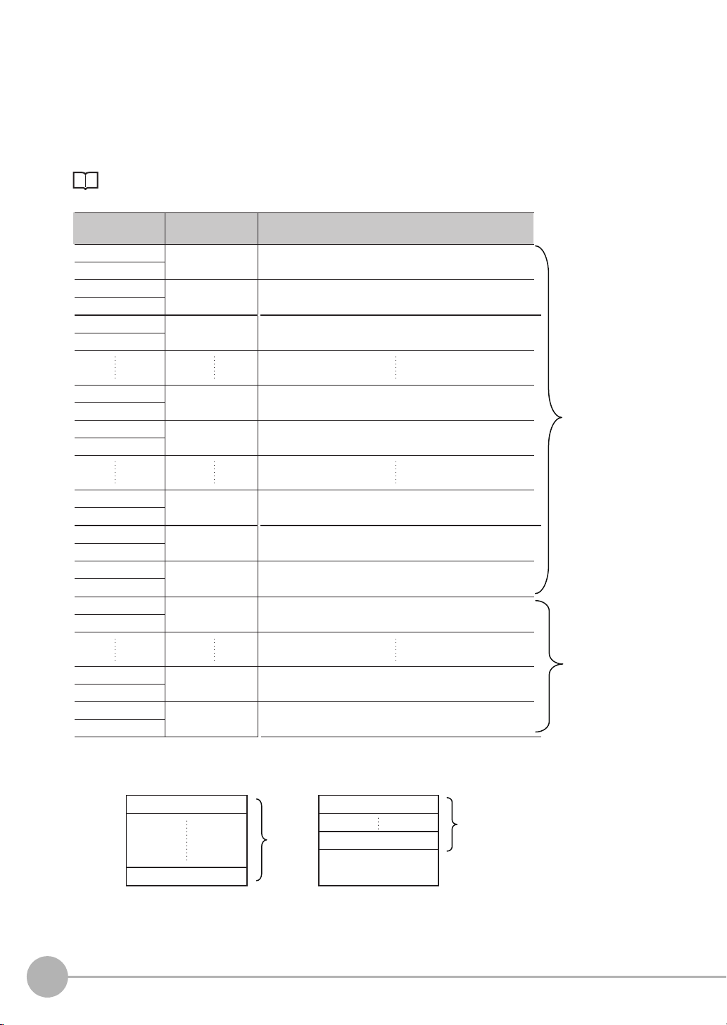
Order of Output of Measurement Data and Characters (Only Supported on the FQ2-S4/CH Series)
When measurement data the data (output data settings 0 to 31) and characters are output together, the
characters are output after the data such as inspection item parameters and calculation results are output.
Example:
Read result 1: ABC
Read result 2: 0123
[Data output] − [Data 0]: 3 (Number of characters: 1)
[Data output] − [Data 1]: 4 (Number of characters: 2)
The following information will be output for the above.
EtherNet/IP, PLC Link, PROFINET
Increment from first
address in output area
+0 Data 0 (4 bytes) Inspection item 0: Number of characters
+1
+2 Data 1 (4 bytes) Inspection item 1: Number of characters
+3
+4 ‘B’ ‘A’ Inspection item 0: Characters “ABC”
+5 00 ‘C’
+6 ‘1’ ‘0’ Inspection item 1: Characters “0123”
+7 ‘3’ ‘2’
+8 00 Filled with zeros. (Only when the character string length is not a
Output data Assigned output data
Upper byte Lower byte
multiple of 4.)
No-protocol (TCP)
3 (Field delimiter) 4 (Record delimiter) ABC (Field delimiter) 0123 (Record delimiter) CR
CR is Delimiter, CR is not output by No-protocol (UDP) Communications.
24
Control Methods Using an External Device
FQ2-S/CH User’s Manual
for Communications Settings
Page 27

Output Data Size and Number of Output Data Upper Value Setting (EtherNet/IP, PLC Link, PROFINET)
Data 0
Output data Setting
Data 1
Data 2
I0.X[0] Inspection item 0: Position X for Search
I0.Y[0] Inspection item 0: Position Y for Search
LPC
(0,30,I1.X,I1.Y)
Inspection item 1: Position X 1st point for Shape Search II
Inspection item 1: Position X 30th point for Shape Search II
Inspection item 1: Position Y 1st point for Shape Search II
Inspection item 1: Position Y 30th point for Shape Search II
Data 3 LPR
(0,10,I2.X,I2.Y)
Inspection item 2: Position X 1st point for Shape Search II
Inspection item 2: Position Y 1st point for Shape Search II
Inspection item 2: Position X 10th point for Shape Search II
Inspection item 2: Position Y 10th point for Shape Search II
328
bytes
When more than one inspection result is output, the size of the data that is output for the data output settings
could exceed the limit that is set in the [Max output data] (number of output data upper value) parameter
setting.
If that occurs, increase the set value of the number of output data upper value setting or adjust the output data
settings so that data output size is not exceeded.
If the size of the data that is output exceeds the data size that can actually be output (output data limit), the
remaining data is handled as follows in each communication protocol.
• EtherNet/IP, PROFINET: The remaining data is divided and output over several cycles.
• PLC Link: The remaining data is discarded.
Example
Output data size: 328 bytes
Number of output data upper value setting: 256 bytes
Data Output Settings
1
Overview of Communication Specifications
FQ2-S/CH User’s Manual
for Communications Settings
Control Methods Using an External Device
25
Page 28
EtherNet/IP, PROFINET
+0
Output data Assigned output data
+1
Output data 0
(4 bytes)
Output data 1
(4 bytes)
Output data 2
(4 bytes)
Output data 31
(4 bytes)
Output data 32
(4 bytes)
Output data 61
(4 bytes)
Output data 62
(4 bytes)
Output data 63
(4 bytes)
Output data 0
(4 bytes)
Output data 6
(4 bytes)
Output data 7
(4 bytes)
Inspection item 0: Position X for Search
+2
+3
Inspection item 0: Position Y for Search
+4
+5
Inspection item 1: Position X 1st point for Shape Search II
+62
+63
Inspection item 1: Position X 30th point for Shape Search II
+64
+65
Inspection item 1: Position Y 1st point for Shape Search II
+122
+123
Inspection item 1: Position Y 30th point for Shape Search II
+124
+125
Inspection item 2: Position X 1st point for Shape Search II
+126
+127
Inspection item 2: Position Y 1st point for Shape Search II
+0
+1
Inspection item 2: Position X 2nd point for Shape Search II
+12
+13
Inspection item 2: Position X 10th point for Shape Search II
+14
+15
Inspection item 2: Position Y 10th point for Shape Search II
Offset from first
address in output area
256 bytes
(Data that is
output the
first cycle.
*1
)
72 bytes
(Data that
is output
the second
cycle.
*2
)
The output data that is assigned is output to the output area as shown below.
Output data that exceeds the size (e.g., 256 bytes) that is set for the output data size parameter is separated
over more than one cycle.
To ensure that no data is lost when receiving data that is divided and output over several cycles, use the
handshake function.
Data Output Control with Handshaking: p.30
*1: At the first data output, a GATE (Data Output Completion) signal is output.
*2: If the size of the specified output data exceeds the set value of the output data size setting, the data is output separately as shown below.
26
Control Methods Using an External Device
Output data size setting: 256 bytes
First Data Output
Output data 0 Output data 0
Output data 63
256
bytes
Second Data Output
Output data 7
Zeros are written to
unused bytes.
72 bytes
The previous data will be
overwritten. Adjust the
timing with handshaking to
get the data.
FQ2-S/CH User’s Manual
for Communications Settings
Page 29
PLC Link
+0
Output data Assigned output data
+1
Output data 0
(4 bytes)
Output data 1
(4 bytes)
Output data 2
(4 bytes)
Output data 31
(4 bytes)
Output data 32
(4 bytes)
Output data 61
(4 bytes)
Output data 62
(4 bytes)
Output data 63
(4 bytes)
Output data 64
(4 bytes)
Output data 65
(4 bytes)
Output data 66
(4 bytes)
Inspection item 0: Position X for Search
+2
+3
Inspection item 0: Position Y for Search
+4
+5
Inspection item 1: Position X 1st point for Shape Search II
+62
+63
Inspection item 1: Position X 30th point for Shape Search II
+64
+65
Inspection item 1: Position Y 1st point for Shape Search II
+122
+123
Inspection item 1: Position Y 30th point for Shape Search II
+124
+125
Inspection item 2: Position X 1st point for Shape Search II
+126
+127
Inspection item 2: Position Y 1st point for Shape Search II
+128
+129
Inspection item 2: Position X 2nd point for Shape Search II
+160
+161
Inspection item 2: Position X 10th point for Shape Search II
+162
+163
Inspection item 2: Position Y 10th point for Shape Search II
Offset from first
address in output area
256 bytes
(Data that is
output the
first cycle.)
72 bytes
(The data that
exceeds the
set upper limit
is discarded.)
The output data that is assigned is output to the output area as shown below.
Any output data that exceeds the set value of the [Max output data] (number of output data upper value)
parameter setting (e.g., 256 bytes) is discarded.
For the [Max output data] setting, refer to Initial Settings for PLC Link Communications on page 122.
1
Overview of Communication Specifications
FQ2-S/CH User’s Manual
for Communications Settings
Control Methods Using an External Device
27
Page 30
Parallel Output of Measurement Data (Only Supported on the FQ2-S3/S4/CH Series)
4 bytes
Parallel data output
PLC
0. Measurement data 0
31. Measurement data 31
Reception
buffer
Data output order
Measurement
data 31
Measurement
data 0
GATE
signal
D0 to D31
signals
ON
OFF
Parallel judgement
output D0
Parallel data output
(data 0)
Parallel judgement
output D1
Parallel data output
(data 0)
Parallel judgement
output D15
Parallel data output
(data 0)
D0
D1
D15
When a Parallel Interface Sensor Data Unit is connected to the Sensor, the two types of data output below can
be performed, in addition to output of measurement judgement results.
Output data type Output data
Parallel Data Output The measurement data is output. A maximum of 32 items can be output.
Parallel Judgement Output The judgement results are output. A maximum of 16 judgement result items can be
output. The following two types of judgement results can be output:
• Judgement results for specified inspection items
• Judgement results of set judgement conditions for the specified item values
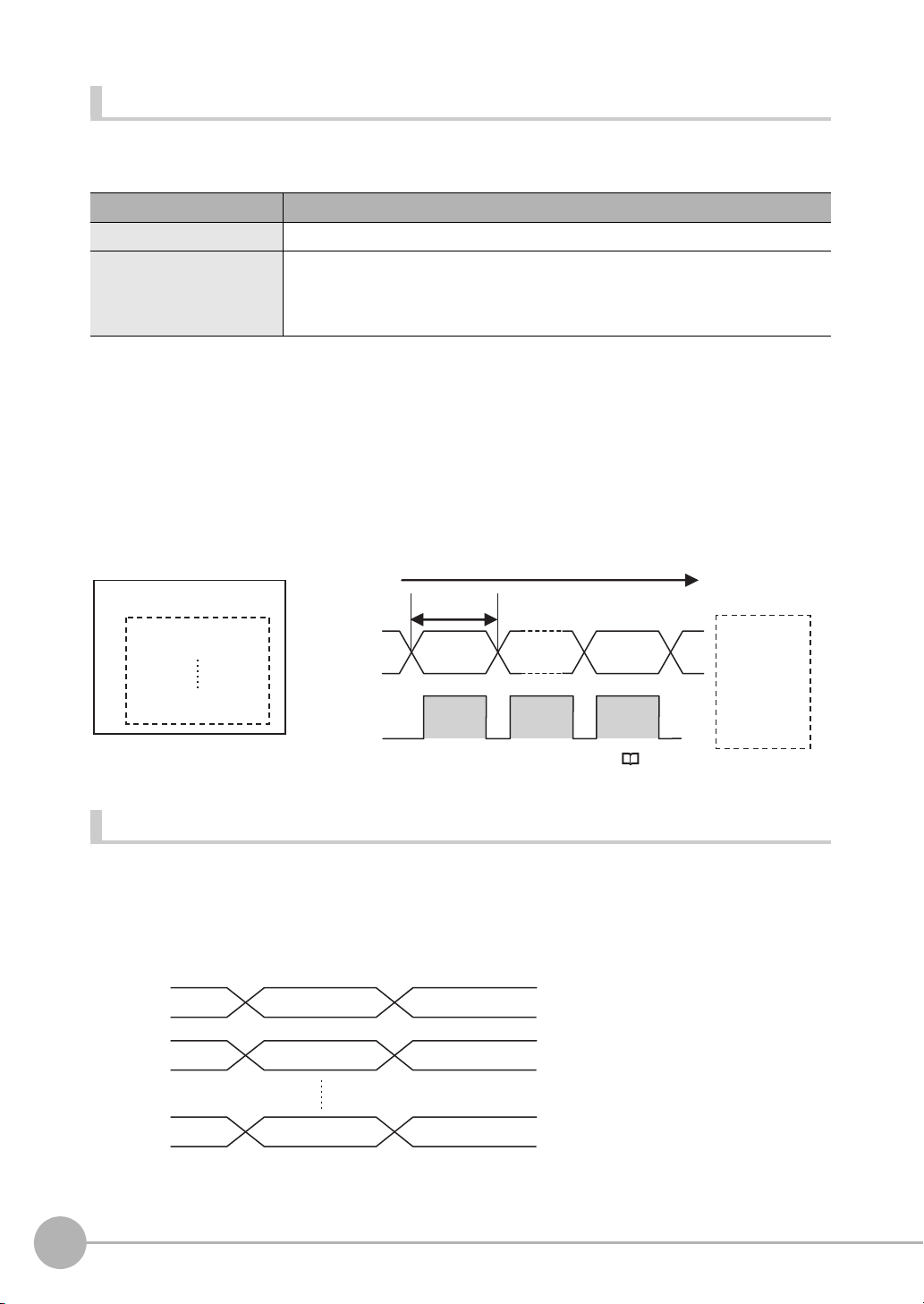
Order of Parallel Data Output
Parallel Output of Multiple Items
Items set to output numbers 0 to 31 of parallel data output are output by item (4 bytes) in ascending order to the
reception buffer of the PLC. The GATE signal turns OFF > ON
When this occurs, the first data item that was output to the PLC reception buffer (data 0) is overwritten by the
next output data item (data 1).
Therefore, the data output to the PLC reception buffer must be saved to PLC memory each time the GATE
signal turns ON for each data item.
*1
at each output.
*1: The operation of the DSA signal depends on whether handshaking for output control is enabled. Data Output Control with Handshak-
Data Output Timing
Output Sequence
If both parallel judgement output and parallel data output are performed at the same time, parallel judgement
output will be performed first followed by parallel data output.
Example: Parallel Judgement Output of D0 to D15 and Parallel Data Output of Data 0
28
Control Methods Using an External Device
ing: p.30.
FQ2-S/CH User’s Manual
for Communications Settings
Page 31

Timing Chart
Overall judgement
Parallel
judgement output
(D0 to D15)
BUSY signal
OFF
ON
OR signal
D signals
OFF
ON
RUN signal
OFF
ON
TRIG signal
OFF
ON
GATE signal
OFF
ON
Measurements executed.
GATE
ON delay
Output time
Output period
Run Mode entered.
ON for 1 ms min.
Setup Mode entered.
The FQ2 starts measurements when it detects the rising edge
(OFF to ON transition) of the TRIG signal.
The following timing chart shows the data output timing for parallel judgement outputs.
1
Overview of Communication Specifications
Output Signals
Signal Function
RUN This signal is ON while the Sensor is ready to take measurement and it is in Run Mode.
The RUN signal is OFF in Setup Mode. Change to Run Mode for operation.
BUSY This signal is ON when the Sensor is performing measurements, changing scenes, or performing other
tasks. Do not input the next command while the BUSY signal is ON.
The process that is currently being executed and the command that is input will not be executed correctly.
OR This signal outputs the overall judgement. The signal is valid when the measurements are completed (i.e.,
when the BUSY signal changes from ON to OFF).
D These signals output the parallel judgement output data and the calculation results of the expressions that
are set for parallel data output.
GATE This signal is used to control the timing of reading the D signals at an external device.
You can set whether the signal turns ON for an OK or for an NG judgement in the [Judgment output condition] output setting.
Changing the Judgement Output ON Conditions: p.44
It is turned ON for the period of time that is required to reliably read the D signals at the external device.
Set the output period so that the total output time is shorter than the measurement interval (i.e., the TRIG
signal input interval).
The GATE signal is output only if parallel judgement output and parallel data output are set. The OR signal
will be ON while the TRIG signal can be input.
Input Signals
Signal Function
TRIG This signal is used to input a measurement trigger from an external device, such as a photoelectric switch.
One measurement is performed on the rising edge (OFF to ON transition) of the TRIG signal. Keep the
TRIG signal ON for at least 1 ms.
FQ2-S/CH User’s Manual
for Communications Settings
Control Methods Using an External Device
29
Page 32

Data Output Control with Handshaking
External device
(1) DSA signal
(3) Measurement results output
(2) GATE signal
Sensor
The timing for data output can be controlled through the DSA and GATE signals.
The handshake function can only be used with EtherNet/IP, PLC Link, PROFINET, and parallel communication
(when a Sensor Data Unit is used).
Requirements for Using Data Output Control with Handshaking
To use data output control, set the output control method to [Handshaking] in the communications protocol
settings. For details, refer to Communications Specifications Settings for each communications protocol.
• Parallel Communications: Refer to Setting Data Communications Specifications: p.66.
• PLC Link Communications: Refer to Setting Up PLC Link Communications: p.122.
• EtherNet/IP and PROFINET Communications: Refer to Communications Specifications Settings (p.92 or
p.145).
Handshaking
If the external device does not turn ON the DSA signal, the measurement data will not be output to the external
device from the Sensor.
While the DSA signal is ON, the GATE signal turns ON when the measurement data is output from the Sensor.
The external device receives the measurement data when the GATE signal turns ON.
Signals Used for Handshaking
Signal Name Description
DSA Data Output Request Sig-
nal
GATE Data Output Completion
Signal
*1: If handshaking is not enabled for output control, the GATE signal will also be turned ON when data is output from the Sensor.
This signal is sent from the external device (PLC) to the Sensor to
request data output.
This signal is sent by the Sensor to the external device (PLC) to tell the
PLC when to receive the output data. This signal is sent only while the
DSA signal is ON.
*1
30
(1) The PLC turns ON the DSA signal and waits for the output data.
(2) The Sensor turns ON the GATE signal when the DSA signal is ON and it is ready to output the
measurement results.
(3) The Sensor turns ON the GATE signal and outputs the output data.
Control Methods Using an External Device
FQ2-S/CH User’s Manual
for Communications Settings
Page 33

Receiving Divided Output Data (Using EtherNet/IP)
Wait for the first cycle
of output data.
Measurement trigger
(e.g., TRIG signal) ON
Data Output Request
(DSA) signal
Result Completion
(GATE) signal
Output data
(DATA 0 to 7)
Wait for the second
cycle of output data.
ON
OFF
ON
OFF
ON
OFF
(2) (3) (4)(1)
First cycle of
output data
(256 bytes)
Second cycle of
output data
In EtherNet/IP, if the data size of the set output data exceeds the data size that the Sensor can actually output
in one cycle (256 bytes), the data is divided and output over multiple cycles.
In this case, use handshaking as shown below to receive the multiple cycles of output data.
Example: EtherNet/IP Communications with Handshaking
1 When the first data is received, the user (PLC) turns ON the measurement trigger and the DSA
signal.
2 The Sensor turns ON the GATE signal when the DSA signal is turned ON and outputs the first
data.
3 The user (PLC) turns OFF the DSA signal again when the GATE signal turns ON. Then, the user
(PLC) confirms the output data received in the PLC Data Output Area and moves the received
data to another area in PLC I/O memory.
4 The Sensor confirms that the DSA signal is OFF and automatically turns OFF the GATE signal.
5 When reception of the output data is completed and the GATE signal turns OFF, the user (PLC)
turns on the DSA signal again and waits for the second cycle of data which could not be sent in
the first cycle and was divided.
6 When the second data is output, the second data output is received when the GATE signal is
turned ON and steps 3 and 5 above are repeated.
1
Overview of Communication Specifications
Steps 3 through 5 above are repeated for all subsequent data output items.
FQ2-S/CH User’s Manual
for Communications Settings
Control Methods Using an External Device
31
Page 34

MEMO
32
Control Methods Using an External Device
FQ2-S/CH User’s Manual
for Communications Settings
Page 35

Controlling Operation and Outputting Data with a Parallel Connection
2-1 Controlling Operation and Outputting Data with the Sensor's
Standard Parallel Connection . . . . . . . . . . . . . . . . . . . . . . . . . . . . . . . .34
2-2 Controlling Operation and Outputting Data with a Parallel
Interface Sensor Data Unit. . . . . . . . . . . . . . . . . . . . . . . . . . . . . . . . . . .60
allel Connection
2
Controlling Operation and Outputting Data with a Par-
Page 36

2-1
(2) Measurements
performed
(1) Measurement
trigger input
(3) Judgement
results output
Trigger Sensor
FQ2 Vision Sensor
External device
(3) Judgement results
output (overall
judgement: OR
signal)
Retained until the next
judgement results are
output.
Turned ON when overall judgement is NG.
(2) Executing
measurement
processing
(BUSY signal)
This signal stays ON until the next
measurement trigger can be input.
*1
You can confirm if measurements are in progress.
The trigger to perform measurements once is turned ON.
(1) Measurement
trigger input
(TRIG signal)
ON
OFF
ON
OFF
ON while measurements are in progress
Measurement
trigger input
(TRIG signal)
OFF
ON
BUSY signal
OFF
ON
OFF
ON
READY signal
ON while measurements are in progress
OFF while measurements are in progress
When the measurement
trigger is received, the BUSY
signal turns ON and the
READY signal turns OFF.
Important
Controlling Operation and Outputting Data with the Sensor's Standard Parallel Connection
This section explains how to directly connect the Sensor to external devices with the I/O cable, and control the
Sensor and execute output.
Basic Operation with a Parallel Connection
This section describes the basic connections and signal flow with external devices.
With the default settings, the Sensor operates in the following manner.
*1: You can also use the READY signal, which will turn ON when a measurement trigger can be input.
You can assign the READY signal to any output from OUT0 to OUT2.
( Getting Individual Judgements and Expression Judgements: p. 41)
• Create the ladder program to control the TRIG and IN5 input signals so that they do not turn ON while the BUSY
signal is ON. If not, a TRIG input error will occur and the ERROR signal will turn ON.
• Operation When the Sensor Power Supply Is Turned ON
The BUSY signal will operate as shown below when the Sensor’s power supply is turned ON.
Create the ladder program in the PLC or other external device so that the BUSY signal is ignored while it turns OFF,
ON, and OFF again for up to 5 s after the power supply is turned ON.
34
Controlling Operation and Outputting Data with the Sensor's Standard Parallel Connection
FQ2-S/CH User’s Manual
for Communications Settings
Page 37

24 V
BUSY
ON
OFF
0 V
Max 5 sec
Sensor system is initializing.
The time of initializing
depends on the scene data.
Turns OFF when the
Sensor is ready for
operation.
Power supply
Note
You can mount a Parallel Interface Sensor Data Unit to enable using other signals and increase the number of signals that you can use with parallel communications.
And in addition to outputting OR judgement results, you can also use a Parallel Interface Sensor Data Unit to output
the judgement results of judgement conditions that you set for parallel output (called parallel judgement output) and
the results of measurement values and expressions for inspection items (called parallel data output).
Controlling Operation and Outputting Data with a Parallel Interface Sensor Data Unit: p. 60
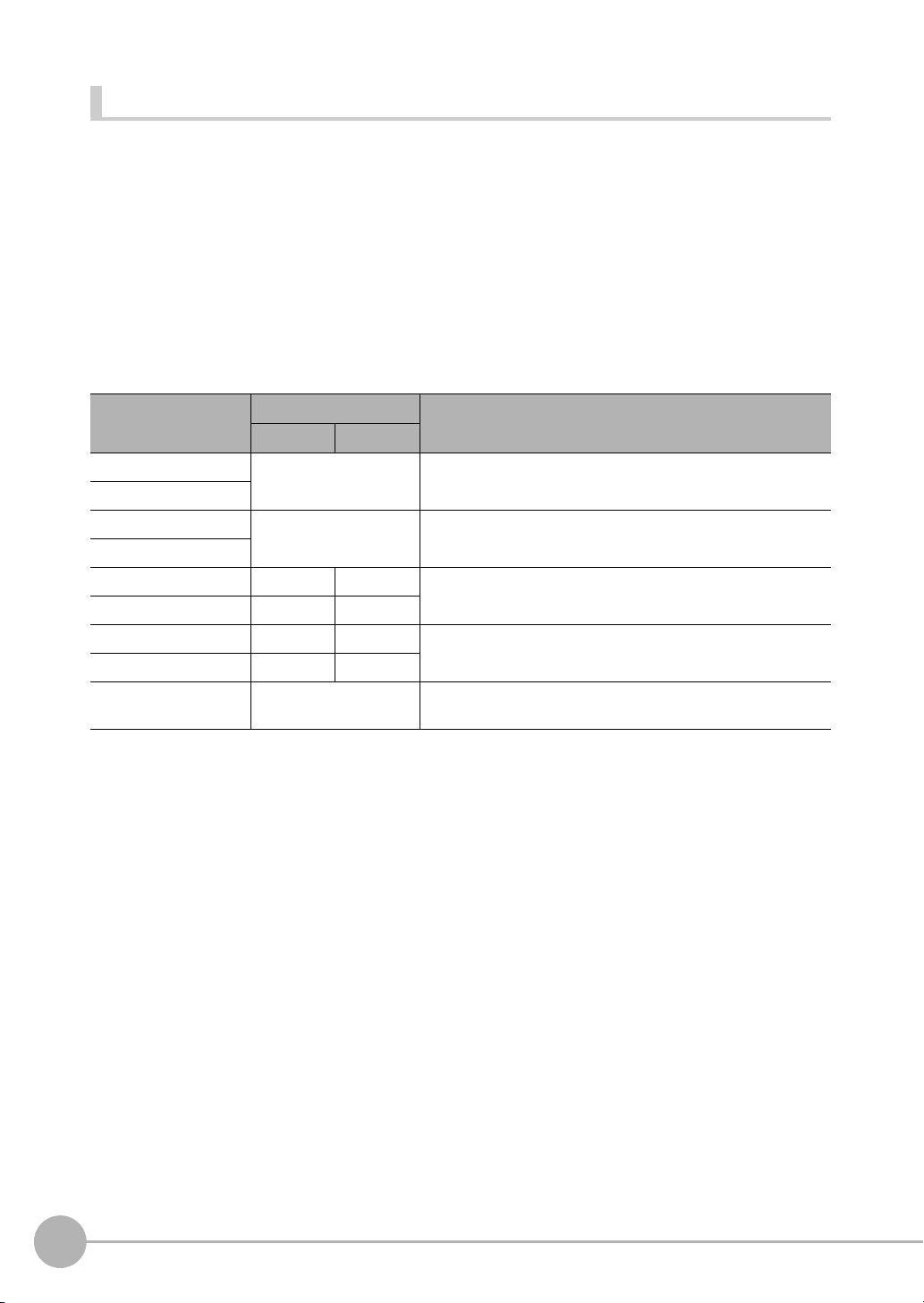
Configuring the Operation
The following settings can be selected depending on the system configuration and application.
Type of change Change Reference
Changing the type of measurement trigger Performing continuous measurements p. 37
Changing the output method of the judgement
results
Changing the polarity of the BUSY output Reversing the polarity of the BUSY signal p. 44
Changing the BUSY output condition Adjusting the end timing of the BUSY signal p. 45
Changing the polarity of the output signals
(OUT1 to OUT2)
Selecting the types of commands that can be
used
Obtaining individual judgement results p. 41
Adjust the judgement output timing p. 42
Changing the judgement output ON conditions p. 44
Reversing the output polarity of OUT1 to OUT2 p. 45
Changing the commands used in IN0 to IN5 p. 45
allel Connection
2
Controlling Operation and Outputting Data with a Par-
FQ2-S/CH User’s Manual
for Communications Settings
Controlling Operation and Outputting Data with the Sensor's Standard Parallel Connection
35
Page 38

Setting the Measurement Trigger
(2) Performs
measurements once
Trigger input Sensor
Or other
device
(1) TRIG signal ON
OFF
ON
OFF
ON
Turned ON when overall judgement is NG.
(OR output: ON for NG)
OR signal
ON while measurements are
being processed (depends
on BUSY output conditions)
BUSY signal
TRIG signal
ON for 1 ms min.
Important
The measurement trigger can be chosen from the following two types:
• One-shot measurement: One measurement is performed for each external trigger.
• Continuous measurement: Measurements are performed continuously.
Performing One Measurement for Each External Trigger
A measurement trigger is input as the TRIG signal from a proximity sensor, PLC, or other external device.
One measurement is performed when the TRIG signal turns ON.
Wiring
36
Color Signal Description
Pink TRIG Trigger signal
Black OUT0 (OR) Overall judgement (default
Orange OUT1 (BUSY) Processing in progress (default
assignment)
assignment)
The signals shown at the left are used.
Refer to the following information for signal wiring.
Section 2 Installation and Connections
in Vision Sensor FQ2-S/CH Series
User's Manual (Cat. No. Z337)
Timing Chart
1. Turn ON the TRIG signal while the BUSY signal is OFF.
2. Measurement begins and the BUSY signal is turned ON during the measurement process.
3. When the measurement has been finished, the measurement result is output using an OR signal, and the
BUSY signal is turned OFF.
*1: You can also set the signal to be turned OFF after data logging, image logging, or displaying results in the [BUSY output].
When the Brightness Correction Mode is ON, the timing when images are taken is delayed.
Section 3 Taking Images
in Vision Sensor FQ2-S/CH Series User's Manual (Cat. No. Z337)
Controlling Operation and Outputting Data with the Sensor's Standard Parallel Connection
*1
FQ2-S/CH User’s Manual
for Communications Settings
Page 39

Sample Ladder Program
SET
TRIG
W0.00 OUT1
0000
#2
TRIG
TMHH
RSET
TRIG
T0000
RSET
W0.00
++L
1000
++L
1002
OUT0
OUT0
OUT1
Single
measurement
command bit
BUSY signal
When the single measurement
command bit (W0.00) turns
ON, the TRIG signal is turned
ON if the BUSY signal is OFF.
TRIG signal
BUSY signal OR signal
OR signal
The TRIG signal is kept ON for
2 ms and then turned OFF.
When the BUSY signal turns OFF to
indicate that the measurement has been
finished, the judgement result is added
to the total count.
OK measurements: CIO 1000
NG measurements: CIO 1002
Important
PLC
(2) Performs continuous
Or other
device
(1) IN5 signal ON (IN0 to IN4 are OFF)
The following sample program is used to input a TRIG signal to perform a single measurement. A single
measurement will be performed when W0.00 turns ON.
• I/O Signal Allocations
allel Connection
2
Controlling Operation and Outputting Data with a Par-
Signal Address
Output signals OUT0 (OR signal) CIO 0.00
Input signals TRIG CIO 1.00
The BUSY signal will remain ON while the measurement is being executed.
Performing Continuous Measurements
Continuous measurements are performed while the continuous measurement command is input from an
external device.
Immediately after a measurement is performed, the next measurement is performed.
This is repeated while a continuous measurement command is input with the IN0 to IN5 signals.
FQ2-S/CH User’s Manual
for Communications Settings
OUT1 (BUSY signal) CIO 0.01
Controlling Operation and Outputting Data with the Sensor's Standard Parallel Connection
37
Page 40

Note
OFF
ON
OFF
ON
OFF
ON
OR signal
Turned ON when overall judgement is NG
(OR output: ON for NG)
ON while measurements are
being processed (depends on
BUSY output conditions)
BUSY signal
Start continuous measurements
End continuous measurements
IN5 signal
IN0 to IN4 signals
are OFF
Allow 5 ms min. and then turn ON IN5.
This function can be used only when the input mode is set to Expanded Mode.
Changing the Types of Commands That Can Be Used: p. 45
Wiring
Color Signal State Description
Gray IN0 OFF Command parameters for continu-
Green IN1 OFF
Red IN2 OFF
White IN3 OFF
Purple IN4 OFF
Ye l l o w I N 5 ON Command input for continuous
Black OUT0 (OR) -- Overall judgement (default assign-
Orange OUT1 (BUSY) -- Processing in progress (default
ous measurements
measurements
ment)
assignment)
Timing Chart
The signals shown at the left
are used.
Refer to the following information for signal wiring.
Section 2 Installation
and Connections
in Vision Sensor
FQ2-S/CH Series
User's Manual
(Cat. No. Z337)
1. Turn ON IN5 while IN0 to IN4 are OFF. If status is held while the BUSY signal is OFF, continuous
2. Continuous measurements end when IN5 is turned OFF.
38
Controlling Operation and Outputting Data with the Sensor's Standard Parallel Connection
measurements will begin and the BUSY signal will remain ON while continuous measurements are being
performed.
FQ2-S/CH User’s Manual
for Communications Settings
Page 41

Sample Ladder Program
MOV
#0000
Q:1
W0.00
0000
#5
TMHH
SET
IN5
T0000
OUT1
W0.00
RSET
W0.00
RSET
IN5
W0.01
RSET
W0.00
Continuous
measurement
command bit
Continuous
measurement
command bit
BUSY signal
Continuous
measurement
stop bit
When the continuous measurement command
bit (W0.00) turns ON, the command
parameter for continuous measurements
(00000) is output to Q:1 (IN0 to IN4).
If the BUSY signal is OFF 5 ms after the
command parameter is output, the command
input for continuous measurements (IN5) is
turned ON and continuous measurements start.
When the continuous measurement stop bit
(W0.01) turns ON, the command input for
continuous measurements (IN5) is turned
OFF and continuous measurements stop.
The following sample program is used to input a IN5 signal to perform continuous measurements. Continuous
measurements will be started when W0.00 turns ON and stopped when W0.01 turns ON.
allel Connection
2
Controlling Operation and Outputting Data with a Par-
• I/O Signal Allocations
Signal Address
Output signals OUT1 (BUSY signal) CIO 0.01
Input signals IN0 CIO 1.08
IN1 CIO 1.09
IN2 CIO 1.10
IN3 CIO 1.11
IN4 CIO 1.12
IN5 CIO 1.15
FQ2-S/CH User’s Manual
for Communications Settings
Controlling Operation and Outputting Data with the Sensor's Standard Parallel Connection
39
Page 42

Setting the Outputs
OK
NG
OK
Inspection
item 31
If there is even one NG judgement,
the overall judgement will be NG
and the output will be turned ON.
NG (OR signal ON)
Inspection
item 1
Overall judgement
Inspection
item 0
Individual judgement results
OK
Expression
OFF
ON
OFF
ON
Overall judgement
Turned ON when overall
judgement is NG.
(OR output: ON for NG)
OR signal
ON while measurements are
being processed (depends
on BUSY output conditions)
BUSY signal
TRIG signal
ON for 1 ms min.
Using the Overall Judgement Result
When the results of the inspection items are judged, if even one individual judgement result is NG, the OR
output signal is turned ON.
Note
• The overall judgement result output signal can also be turned ON when all individual judgement results are OK.
Changing the judgement output ON condition: p. 44
• You can select whether to include the judgement result of one of the expressions (0 through 31) in the overall judgement.
Section 4 Setting Up Inspections
in Vision Sensor FQ2-S/CH Series User's Manual (Cat. No. Z337)
• You can adjust the timing for outputting the OR signal and the ON time after judgement processing.
40
Adjust the Judgement Output Timing: p. 42
Wiring
Color Signal Description
Black OUT0 (OR) Overall judgement (default
assignment)
The signals shown at the left are used.
Refer to the following information for signal wiring.
Section 2 Installation and Connections
in Vision Sensor FQ2-S/CH Series User's Manual
(Cat. No. Z337)
Timing Chart
The OR signal that is output is held until the next overall judgement is output.
Controlling Operation and Outputting Data with the Sensor's Standard Parallel Connection
FQ2-S/CH User’s Manual
for Communications Settings
Page 43

Note
Note
Important
The timing for updating the OR signal and the ON time after judgement processing can be adjusted.
Adjusting the judgement output timing: p. 42
Getting Individual Judgements and Expression Judgements
Up to three judgement results of individual inspection items (item judgement signals OR0 to OR31) and
expression judgements (expression 0 judgement to expression 31 judgement) can be assigned to terminals
OUT0 to OUT2 and output to external devices.
Output terminal Default assignment Output signals that can be assigned
OUT0 OR (Total judgement) • Control signals: OR, BUSY, ERROR, READY, and RUN
OUT1 BUSY
OUT2 ERROR
The timing for updating the OR0 to OR31 signals and the ON time after judgement processing can be changed.
Adjusting the judgement output timing: p. 42
STG (strobe trigger)
• Item judgements: OR0 (Item 0 judgement) to OR31
(Item 31 judgement)
• Expression judgements: Expression 0 judgement to
expression 31 judgement
allel Connection
2
Controlling Operation and Outputting Data with a Par-
During Sensor startup, the user output assignments of OUT1 and OUT2 output terminals are not effective. The output
assignments assume the initial state and operate as follows.
• OUT1: Turns ON as a BUSY signal.
Operation When the Sensor Power Supply Is Turned ON: p.34
• OUT2: Turns ON as an ERROR signal for about 20 ms immediately after sensor startup starts.
If you want to output a READY signal during Sensor startup, assign the READY signal to OUT0.
Wiring
Example: Signals are assigned to terminals OUT0 to OUT2 as shown below.
• OUT0: Item 2 judgement (OR2)
• OUT1: Item 5 judgement (OR5)
• OUT2: Item 14 judgement (OR14)
Color Signal Description
Black OUT0 (OR2) Outputs the judgement for
Orange OUT1 (OR5) Outputs the judgement for
Light
blue
OUT2 (OR14) Outputs the judgement for
OR2.
OR5.
OR14.
The signals shown at the left are used.
Refer to the following information for signal wiring.
Section 2 Installation and Connections
in Vision Sensor FQ2-S/CH Series
User's Manual (Cat. No. Z337)
As described above, if terminals OUT0 to OUT2 are all assigned to individual judgement output signals, the
BUSY signal and ERROR signal assigned as the default settings will no longer be output.
FQ2-S/CH User’s Manual
for Communications Settings
Controlling Operation and Outputting Data with the Sensor's Standard Parallel Connection
41
Page 44

Timing Chart
OFF
ON
OFF
ON
OR1 signal
Turned ON when individual
judgement is NG.
(OR output: ON for NG)
OR0 signal
Turned ON when individual
judgement is NG.
(OR output: ON for NG)
Example:
ON while measurements are
being processed (depends
on BUSY output conditions)
BUSY signal
TRIG signal
ON for 1 ms min.
Individual
judgement
*1
OFF
ON
OFF
ON
OFF
ON
NGOK
Held until the next
judgement result is output
Overall judgement
(OR output: ON for NG)
OR signal
ON while measurements are being
processed (depends
on BUSY output
conditions)
BUSY signal
TRIG signal ON for 1 ms min.
Output OR0 to OR31 signals are held until the next judgement output.
*1: The timing for updating the OR signal is when the measurement results are finalized, regardless of the output settings of the BUSY signal
(BUSY output conditions).
Settings
[In/Out] − [I/O setting] − [I/O setting] − [Output]
1 Press [OUT0].
2 Press [OR2 (Item 2 judgement)].
OR2 output signal was assigned to OUT0.
3 Assign the others in the following manner.
OUT1: OR5
OUT2: OR14
Adjusting the Judgement Output Timing
The output timing of the OR signal or OR0 to OR31 signals can be selected from two modes depending on the
external device.
Selecting the OFF Timing
• Level output (default)
The status of the output OR signal is held until the next OR signal is output.
42
Controlling Operation and Outputting Data with the Sensor's Standard Parallel Connection
for Communications Settings
FQ2-S/CH User’s Manual
Page 45

• One-shot output
OFF
ON
OFF
ON
OFF
ON
NGOK
Turns OFF.
One-shot
output time
Overall judgement
(OR output: ON for NG)
OR signal
ON while
measurements are
being processed
(depends on BUSY
output conditions)
BUSY signal
TRIG signal
ON for 1 ms min.
OFF
ON
OFF
ON
OFF
ON
NG
One-shot
output time
Overall judgement
(OR output: ON for NG)
OR signal
ON while
measurements are
being processed
(depends on BUSY
output conditions)
BUSY signal
TRIG signal ON for 1 ms min.
One-shot
output delay
The status of the output OR signal is turned OFF after a specified time has passed. (Setting range: 0 to 1,000 ms)
Delaying the Output Timing
When using one-shot output, the output timing of the OR signal can be delayed. (Setting range: 0 to 1,000 ms)
allel Connection
2
Controlling Operation and Outputting Data with a Par-
Settings
[In/Out] − [I/O setting] − [I/O setting] − [Output]
1 Press [Output mode] and press [Level output] or
[One-shot output].
2 Press [Output delay] and set the one-shot output de-
lay.
3 Press [OK].
4 Press [Output time] and set the one-shot output time.
5 Press [OK].
FQ2-S/CH User’s Manual
for Communications Settings
Controlling Operation and Outputting Data with the Sensor's Standard Parallel Connection
43
Page 46

Item Description
Important
Important
Output mode One-shot output After the measurement results are finalized, if the judgement output ON condition
Level output (default) The judgement is output after measurement results are finalized and the ON/OFF
Output delay When one-shot output mode is selected, this parameter sets the delay from when
Output time When one-shot output mode is selected, this parameter sets the time that the OR
is met, the OR signal is turned ON for the one-shot output time. It is then turned
OFF once the specified time has expired.
status of the OR signal is held until it is changed for the next measurement result.
a measurement is completed until when the OR signal turns ON. (Setting range: 0
to 1,000 ms)
signal is ON. (Setting range: 1 to 1,000 ms)
When one-shot output is selected as the output mode, make the following value smaller than the trigger input period.
• One-shot delay time + One-shot output time
Changing the Judgement Output ON Conditions
The ON condition for the OR signal or the OR0 to OR31 signals can be set to be output when the judgement
results are OK or when they are NG. The default setting is when they are NG.
Settings
[In/Out] − [I/O setting] − [I/O setting] − [Output] − [OR output]
Item Description
OR output OK: ON The output is turned ON if the judgement is OK.
NG: ON (default) The output is turned ON if the judgement is NG.
For the overall judgement, the output is turned ON if all judgements are OK.
For the overall judgement, the output is turned ON if even one judgements is NG.
Changing the Polarity of the BUSY Output
The Sensor turns ON the BUSY output signal during measurements and other processing to indicate that a
measurement trigger cannot be received. The polarity of the BUSY signal can be reversed so that it is ON only
when a trigger signal can be received.
In the default settings, the BUSY signal is assigned to OUT1. If you change the assignment of the BUSY signal,
change the polarity of the corresponding output.
Settings
[In/Out] − [I/O setting] − [I/O setting] − [Output] − [OUT1 Polarity]
Item Description
OUT1 Polarity Positive (default) The BUSY signal is ON while the Sensor is processing data.
Negative The BUSY signal is ON while the Sensor can receive a trigger signal.
All timing charts in this manual show the operation of the BUSY signal with positive polarity (the default setting). If you
change the polarity of the BUSY signal, take this into consideration when reading the timing charts.
44
Controlling Operation and Outputting Data with the Sensor's Standard Parallel Connection
FQ2-S/CH User’s Manual
for Communications Settings
Page 47

Adjusting the End Timing of the BUSY Signal
Important
The end timing of the BUSY signal can be changed.
[In/Out] − [I/O setting] − [I/O setting] − [Output] Tab Page − [BUSY output]
Item Description
BUSY output Measurement (default) The BUSY signal turns OFF when the measurement is completed.
Data logging The BUSY signal turns OFF when data logging is completed.
Image logging The BUSY signal turns OFF when image logging is completed.
Result display The BUSY signal turns OFF when the result display is completed.
Do not disconnect the Ethernet cable between the Sensor and the Touch Finder if the Sensor and Touch Finder are
connected through an Ethernet switch and the BUSY output condition is set to [Data logging], [Image logging], or
[Result display].
The Sensor will wait for the Touch Finder to answer, and the results and measurement time will be affected.
To disconnect the Sensor and Touch Finder during measurements in the above situation, clear the selection of the
Sensor from the list of Sensors on the Touch Finder before you disconnect the cable.
Changing the Polarity of the Output Signals
allel Connection
2
Controlling Operation and Outputting Data with a Par-
You can change the polarity of the output signals that are assigned to OUT0 to OUT3 (regardless of what
signal is assigned to the output).
Settings
[In/Out] − [I/O setting] − [I/O setting] − [Output] − [OUT0 Polarity], [OUT1 Polarity] or [OUT2
Polarity]
Item Description
OUT0 Polarity,
OUT1 Polarity, or
OUT2 Polarity
Positive (default) The output signal that is assigned to OUT0 to OUT3 is turned ON when the Sen-
Negative The output signal that is assigned to OUT0 to OUT3 is turned ON when the Sen-
sor is executing a process.
sor can receive the trigger.
Changing the Types of Commands That Can Be Used
You can select the types of commands used in IN0 to IN5.
Settings
[In/Out] − [I/O setting] − [I/O setting] − [Input] − [Input mode]
Item Description
Input mode Standard mode (default) IN0 to IN4 are only used for line process changes.
Expanded mode Enables use of IN0 to IN4 for commands other than line process changes.
A maximum of 32 scenes are selectable.
A maximum of 16 scenes are selectable.
FQ2-S/CH User’s Manual
for Communications Settings
Controlling Operation and Outputting Data with the Sensor's Standard Parallel Connection
45
Page 48

Controlling the Sensor from an External Device
Important
0
(IN40IN30IN20IN11IN0)
The following Sensor functions can be controlled with command inputs from an external device without
connecting the Touch Finder.
Function Description Reference
Changing the Scene This command changes the scene when the line process changes. p. 46
Registering the Measurement Reference Again
Turning the ERROR Signal OFF This command turns the ERROR signal OFF. p. 51
Performing Continuous Measurements
Clearing Measurement Values This command clears the measurement values. p. 52
Saving Data in Sensor This command saves the settings data to the Sensor. p. 57
Retrying Inspection by External
Signal (trigger retry)
Resetting the Sensor This command resets the Sensor. p. 55
Executing External Teaching This command executes teaching for all target items. p. 58
Change to Expanded Mode before you input any command other than a command to change the scene. If you change
to Expanded Mode, you can use any of the commands. However, in Expanded Mode, you can change to only 16
scenes with the parallel SCENE command instead of 32 scenes.
This command re-registers the judgement references for measurement when levels are changed.
This command continues measurement is performed while this command is input. p. 37
This command continues inspection when the trigger signal is ON. p. 52
p. 49
Changing the Types of Commands That Can Be Used: p. 45
Changing the Scene
This section describes how to change to a specified scene number.
Wiring
Color Signal State Description
Input Mode
Standard Mode Expanded Mode
Gray IN0 Scene number
Green IN1
Red IN2
White IN3
Purple IN4 ON
Ye l l o w I N 5 ON Trigger to change the scene
Orange OUT1
(BUSY)
(0 to 31)
Scene number
(0 to 15)
-- Processing in progress (default)
Specifies the scene number.
IN0 to IN4 correspond to the binary
bits of the scene number.
Example: To change to scene 1 in
Standard Mode, specify
as follows:
The signals shown at the left
are used.
Refer to the following
information for signal wiring.
Section 2 Installation
and Connections
in Vision Sensor
FQ2-S/CH Series
User's Manual
(Cat. No. Z337)
46
Controlling Operation and Outputting Data with the Sensor's Standard Parallel Connection
FQ2-S/CH User’s Manual
for Communications Settings
Page 49

Timing Chart
Important
Note
IN0 to IN4 signals
(in Standard Mode)
IN5 signal
BUSY signal
*1: In Expanded Mode, specify scene numbers 0 to 15 using the
The scene numbers that can be used depend on the input mode.
[Standard mode] (default): Scene 0 to 31
[Expanded mode]: Scene 0 to 15
Changing the Types of Commands That Can Be Used: p. 45
*1
ON
OFF
ON
OFF
IN0 to IN3 signals.
Scene number 0 to 31
Allow 5 ms min. and then turn ON IN5.
ON for 1 ms min.
Start scene change
End scene change
1 Specify the scene number
with the IN0 to IN4 signals.
(Standard Mode)
2 Turn ON the IN5 signal while
the BUSY signal is ON to
change the scene to the
specified scene.
3 The BUSY signal turns ON
while the scene is being
switched.
allel Connection
2
Controlling Operation and Outputting Data with a Par-
• Even in Expanded Mode, you can use menu commands or Ethernet no-protocol commands to change to scenes
0 to 31.
• The input mode can be set on both standard models and single-function models.
FQ2-S/CH User’s Manual
for Communications Settings
Controlling Operation and Outputting Data with the Sensor's Standard Parallel Connection
47
Page 50

Sample Ladder Program
MOV
#1100
Q:1
TMHH
0000
#5
TMHH
0001
#2
SET
IN5
RSET
IN5
SET
W0.01
W0.00
T0000
IN5
OUT1
BUSY
W0.00
RSET
W0.00
T0001
BUSY
Scene change
bit
Scene change
bit
When the scene change bit (W0.00) turns ON,
the scene number is input to IN0 to IN3 and
IN4 is turned ON.
If the BUSY signal is OFF 5 ms after the
scene number is input, the trigger to change
the scene (IN5) is turned ON.
The trigger to change the scene (IN5) is kept
ON for 2 ms and then turned OFF.
When the BUSY signal turns OFF to indicate
that the scene has been changed, processing
after changing the scene is performed (W0.01
turned ON).
Note
Important
This sample program is used to change the scene when the input mode is set to Expanded Mode. The scene
changes to scene 1 when W0.00 turns ON.
48
• I/O Signal Allocations
Signal Address
Output signals OUT1 (BUSY signal) CIO 0.01
Input signals IN0 CIO 1.08
IN1 CIO 1.09
IN2 CIO 1.10
IN3 CIO 1.11
IN4 CIO 1.12
IN5 CIO 1.15
The amount of time it takes for a scene to change depends on the scene settings. The BUSY signal turns ON while
scene change is being executed, so the scene change execution time can be checked with the BUSY signal.
If the cycle time is too long, the PLC may not be able to detect when the BUSY signal is ON. If necessary, turn OFF
W0.00 after a suitable time elapses.
Controlling Operation and Outputting Data with the Sensor's Standard Parallel Connection
FQ2-S/CH User’s Manual
for Communications Settings
Page 51

Registering the Measurement Reference Again
OFF
ON
OFF
ON
End re-registering
Start re-registering
BUSY signal
IN5 signal
ON for 1 ms min.
Allow 5 ms min. and then turn
ON IN5.
IN0 to IN4 signals
When the line process is changed or otherwise, the model and reference color can be reregistered based on
the previously loaded image. Data that can be re-registered with the reregistration command are shown below.
Inspection item Re-registered data
Search, Shape Search II Model data
Color Data Reference color (hue, saturation, and brightness)
Edge Position, Edge Width, Area None
Note
• This command is only valid in Expanded Mode.
• Application is possibly only from the Run Mode
• If the parameter is applicable to more than one inspection item, it will be re-registered for all inspection items.
Settings
[In/Out] − [I/O setting] − [I/O setting] − [Input] − [Input mode]
Press [Expand mode].
Wiring
allel Connection
2
Controlling Operation and Outputting Data with a Par-
Color Signal State Description
Gray IN0 OFF Command parameter for registering the mea-
Green IN1 OFF
Red IN2 OFF
White IN3 ON
Purple IN4 OFF
Yellow IN5 ON Command input for registering the measurement
Orange OUT1 (BUSY) -- Processing in progress (default)
Timing Chart
surement reference again
reference again
The signals shown at the left are
used.
Refer to the following information for
signal wiring.
Section 2 Installation and
Connections
in Vision Sensor FQ2-S/CH
Series User's Manual
(Cat. No. Z337)
1 Turn OFF IN0 to IN4 and turn ON IN3.
2 Turn ON the IN5 signal while the
BUSY signal is OFF to register the
model data and reference color again
from the image that was just input.
3 The BUSY signal turns ON while the
parameters are being re-registered.
FQ2-S/CH User’s Manual
for Communications Settings
Controlling Operation and Outputting Data with the Sensor's Standard Parallel Connection
49
Page 52

Sample Ladder Program
MOV
#800
Q:1
TMHH
0000
#5
TMHH
0001
#2
SET
IN5
RSET
IN5
SET
W0.01
W0.00
T0000
IN5
OUT1
BUSY
W0.00
RSET
W0.00
T0001
BUSY
Model
re-register bit
Model
re-register bit
When the mode re-register bit (W0.00) turns
ON, IN3 is turned ON.
If the BUSY signal is OFF 5 ms after IN3 turns
ON, the command input for registering the
mode again (IN5) is turned ON.
The command input for registering the mode
again (IN5) is kept ON for 2 ms and then
turned OFF.
When the BUSY signal turns OFF to indicate
that model has been re-registered, processing
after re-registration is performed (W0.01
turned ON).
Note
Important
This sample program is used to input IN5 to re-register a model.
• I/O Signal Allocations
Signal Address
Output signals OUT1 (BUSY signal) CIO 0.01
Input signals IN0 CIO 1.08
IN1 CIO 1.09
IN2 CIO 1.10
IN3 CIO 1.11
IN4 CIO 1.12
IN5 CIO 1.15
The BUSY signal will be ON while the model is being re-registered.
If the cycle time is too long, the PLC may not be able to detect when the BUSY signal is ON. If necessary, turn OFF
W0.00 after a suitable time elapses.
50
Controlling Operation and Outputting Data with the Sensor's Standard Parallel Connection
FQ2-S/CH User’s Manual
for Communications Settings
Page 53

Turning the ERROR Signal OFF
OFF
ON
OFF
ON
OFF
ON
ON for 1 ms min.
Allow 5 ms min. and then
turn ON IN5.
IN0 to IN4 signals
IN5 signal
BUSY signal
ERROR signal
The ERROR signal turns ON when an error occurs.
After removing the cause of the error, turn the ERROR signal OFF using one of the following methods.
Method 1: Input an error clear command from an external device such as a PLC.
Method 2: Input a measurement trigger again.
(For example, turn the TRIG signal ON during a one-shot measurement.)
The ERROR signal will turn OFF when measurement is executed correctly.
Note
• This command is only valid in Expanded Mode.
• This function can be used in Run Mode only.
Wiring
Color Signal State Description
Gray IN0 OFF Command parameter for clearing errors
Green IN1 OFF
Red IN2 ON
White IN3 OFF
Purple IN4 OFF
Ye l l o w I N 5 ON Command input for clearing errors
Orange OUT1 (BUSY) -- Processing in progress (default)
Light blue OUT2 (ERROR) -- ERROR signal (default)
Timing Chart
1 Turn OFF IN0 to IN1 and IN3 to IN4
2 Turn ON the IN5 signal while the
The signals shown at the left
are used.
Refer to the following
information for signal wiring.
Section 2 Installation
and Connections
in Vision Sensor
FQ2-S/CH Series
User's Manual
(Cat. No. Z337)
and turn ON IN2.
BUSY signal is OFF to clear the error.
allel Connection
2
Controlling Operation and Outputting Data with a Par-
FQ2-S/CH User’s Manual
for Communications Settings
Controlling Operation and Outputting Data with the Sensor's Standard Parallel Connection
51
Page 54

Clearing Measurement Values
OFF
ON
The measurement values are
cleared from the Sensor.
OFF
ON
BUSY signal
IN5 signal
ON for 1 ms min.
Allow 5 ms min. and then
turn ON IN5.
IN0 to IN4 signals
This command clears the measurement values that are stored in the Sensor. However, the OR signal and the
output signals that are assigned to OUT0 to OUT2 are not cleared.
Note
• This command is only valid in Expanded Mode.
• This function can be used in Run Mode only.
Wiring
Color Signal State Description
Gray IN0 ON Command parameter for clearing mea-
Green IN1 OFF
Red IN2 ON
White IN3 OFF
Purple IN4 OFF
Ye l l o w I N 5 ON Command input for clearing measure-
Orange OUT1 (BUSY) -- Processing in progress (default)
surement values
ment values
Timing Chart
1 Turn ON IN0 and IN2 and turn OFF
2 Turn ON the IN5 signal while the
The signals shown at the left
are used.
Refer to the following
information for signal wiring.
Section 2 Installation
and Connections
in Vision Sensor
FQ2-S/CH Series
User's Manual
(Cat. No. Z337)
IN1, IN3 and IN4.
BUSY signal is OFF to clear the
measurement values.
Measurement is repeated until all inspection items have been successfully scanned.
Retry inspection ends when any one of the following conditions is satisfied:
(1) The scanning result of all inspection items is OK.
(2) Trigger retry (this command) turns OFF.
(3) The timeout time is exceeded.
52
Controlling Operation and Outputting Data with the Sensor's Standard Parallel Connection
Retrying Inspection by External Signal (Trigger Retry)
Note
• This command is only valid in Expanded Mode.
• This function can be used in Run Mode only.
FQ2-S/CH User’s Manual
for Communications Settings
Page 55

Wiring
OFF
ON
OFF
ON
OFF
ON
IN5 signal
IN0 to IN4 signals
IN5 ON after at least 5 ms
Retry starts
ScanNGScanNGScan
OK
Retry ends
BUSY signal
OR signal
OFF
ON
OFF
ON
OFF
ON
IN5 signal
IN0 to IN4 signals
IN5 ON after at least 5 ms
Retry starts
ScanNGScan
NG
Scan
NG
Scan
NG
Retry ends
BUSY signal
OR signal
Color Signal State Description
Gray IN0 OFF Command parameters for trigger retry
Green IN1 OFF
Red IN2 ON
White IN3 ON
Purple IN4 OFF
Ye l l o w I N 5 ON Command input for trigger retry (this com-
Orange OUT1 (BUSY) -- Busy
Black OUT0 (OR) -- Overall judgment (default)
(this command)
mand)
Timing Chart
• When inspection is OK
1 IN0, IN1 and IN4 are turned OFF, IN2
and IN3 are turned ON.
2 When IN5 is turned OFF > ON with
the BUSY signal OFF, trigger retry
inspection starts.
3 When retry inspection starts, the
BUSY signal turns ON.
4 When the overall judgment turns ON,
retry inspection ends and the BUSY
signal turns OFF.
5 After verifying that the BUSY signal
has turned ON > OFF, IN5 is turned
ON > OFF.
The signals shown at the left
are used.
Refer to the following
information for signal wiring.
Section 2 Installation
and Connections
in Vision Sensor
FQ2-S/CH Series
User's Manual
(Cat. No. Z337)
allel Connection
2
Controlling Operation and Outputting Data with a Par-
• When inspection is NG
FQ2-S/CH User’s Manual
for Communications Settings
1 IN0, IN1 and IN4 are turned OFF, IN2
and IN3 are turned ON.
2 When IN5 is turned OFF > ON with
the BUSY signal OFF, trigger retry
inspection starts.
3 When retry inspection starts, the
BUSY signal turns ON.
4 IN5 is turned OFF and retry inspection
ends. If retry inspection ends but the
overall judgment is NG, the OR signal
turns ON. (Output polarity: When ON
at NG)
Controlling Operation and Outputting Data with the Sensor's Standard Parallel Connection
53
Page 56

Sample Ladder Program
MOV
#0C00
Q:1
TMHH
0000
#5
TMHH
0001
#3000
SET
IN5
RSET
IN5
SET
W0.01
W0.00
T0000
IN5
OUT1
BUSY
W0.00
RSET
W0.00
T0001
BUSY
Trigger retry execution
When trigger retry execution (W0.00)
is turned ON, the command
parameter for sensor restart (001100)
is output to Q:1 (IN0 to IN4).
After trigger retry finishes and the
BUSY signal turns OFF, post trigger
retry processing (W0.01:ON) is
executed.
If the BUSY signal is OFF five
ms after the command parameter
is output, the trigger retry
execution trigger (IN5) turns ON.
After being ON for 3000 ms, the
trigger retry execution trigger
(IN5)turns OFF.
Trigger retry execution
This sample ladder program executes trigger retry when the I/O input mode is Expanded Mode.
Trigger retry is executed at W0.00 ON.
• I/O Signal Allocations
Signal type Address
Output signal OUT1 (BUSY signal) CIO 0.01
Input signals IN0 CIO 1.08
Note
The time the BUSY signal is ON is the trigger retry execution time.
IN1 CIO 1.09
IN2 CIO 1.10
IN3 CIO 1.11
IN4 CIO 1.12
IN5 CIO 1.15
54
Controlling Operation and Outputting Data with the Sensor's Standard Parallel Connection
FQ2-S/CH User’s Manual
for Communications Settings
Page 57

It may happen that the PLC is unable to recognize BUSY signal ON because the sample time is slow or otherwise. In
Important
IN0 to IN4 signals
IN5 ON after at least 5 ms
ON at least 1 ms
IN5 signal
OFF
ON
this event, have W0.00 turn OFF at a suitable time.
Resetting the Sensor
Sensor reset is explained below.
Note
• This command is only valid in Expanded Mode.
• This function can only be used in Run mode.
Wiring
Color Signal State Description
Gray IN0 OFF Command parameters for Sensor reset
Green IN1 ON
Red IN2 OFF
White IN3 ON
Purple IN4 OFF
Yellow IN5 ON Command input for Sensor reset
Orange OUT1 (BUSY) -- Busy (default)
1 IN0, IN2 and IN4 are turned OFF, IN1
2 IN5 is turned OFF > ON with the
3 When the initialization process starts,
The signals shown at the left
are used.
Refer to the following
information for signal wiring.
Section 2 Installation
and Connections
in Vision Sensor
FQ2-S/CH Series
User's Manual
(Cat. No. Z337)
and IN3 are turned ON.
BUSY signal OFF. The BUSY signal
does not turn ON while the restart
command is being received.
the BUSY signal turns ON.
For the initialization process, refer to
the following:
allel Connection
2
Controlling Operation and Outputting Data with a Par-
FQ2-S/CH User’s Manual
for Communications Settings
Operation with Default Configuration: p.34
Controlling Operation and Outputting Data with the Sensor's Standard Parallel Connection
55
Page 58

Sample Ladder Program
MOV
#A00
Q:1
TMHH
0000
#5
TMHH
0001
#2
SET
IN5
RSET
IN5
SET
W0.01
W0.00
T0000
IN5
OUT1
BUSY
W0.00
RSET
W0.00
T0001
BUSY
Sensor restart
When Sensor restart execution (W0.00) is
turned ON, the command parameter for
Sensor restart (001010) is output to
Q:1 (IN0 to 4).
After Sensor restart finishes and the
BUSY signal turns OFF, post Sensor
restart processing (W0.01:ON) is executed.
If the BUSY signal is OFF five ms after
the command parameter is output, the
Sensor restart execution trigger (IN5)
turns ON.
After being ON for 2 ms, Sensor
restart execution (IN5) turns OFF.
Sensor restart
Note
This sample program inputs IN5 to restart the Sensor.
Trigger retry is executed at W0.00 ON.
• I/O Signal Allocations
Signal type Address
Output signal OUT1 (BUSY signal) CIO 0.01
Input signals IN0 CIO 1.08
IN1 CIO 1.09
IN2 CIO 1.10
IN3 CIO 1.11
IN4 CIO 1.12
IN5 CIO 1.15
The time the BUSY signal is ON is the Sensor initialization process execution time.
56
Controlling Operation and Outputting Data with the Sensor's Standard Parallel Connection
FQ2-S/CH User’s Manual
for Communications Settings
Page 59

It may happen that the PLC is unable to recognize BUSY signal ON because the cycle time is slow or otherwise. In
Important
OFF
ON
Saving data
in Sensor started.
Saving data in
Sensor completed.
OFF
ON
BUSY
signal
IN5 signal
ON for 1 ms min.
Allow 5 ms min. and then
turn ON IN5.
IN0 to IN4
signals
this event, have W0.00 turn OFF at a suitable time.
Saving Data in Sensor
You can save the current settings (scene data and system data) in the Sensor.
Note
• This command is only valid in Expanded Mode.
• This function can be used in Run Mode only.
Wiring
Color Signal State Description
Gray IN0 ON Command parameters for saving data to
Green IN1 OFF
Red IN2 OFF
White IN3 OFF
Purple IN4 OFF
Ye l l o w I N 5 ON Command input for saving data to the
Orange OUT1 (BUSY) -- Processing in progress (default)
the Sensor
Sensor
Timing Chart
1 Turn ON IN0 and turn OFF IN1 to IN4.
2 Turn ON the IN5 signal while the
BUSY signal is OFF to save the data
in the Sensor.
The signals shown at the left
are used.
Refer to the following
information for signal wiring.
Section 2 Installation
and Connections
in Vision Sensor
FQ2-S/CH Series
User's Manual
(Cat. No. Z337)
allel Connection
2
Controlling Operation and Outputting Data with a Par-
FQ2-S/CH User’s Manual
for Communications Settings
Controlling Operation and Outputting Data with the Sensor's Standard Parallel Connection
57
Page 60

Executing External Teaching
Teaching for all registered items can be executed using the current input image.
Note
• This command is only valid in Expanded Mode.
• Application is possibly only from the Run Mode
• If the parameter is applicable to more than one inspection item, it will be external teaching for all inspection items.
Wiring
Color Signal State Description
Gray IN0 ON Command parameter for external teaching
Green IN1 OFF
Red IN2 OFF
White IN3 ON
Purple IN4 OFF
Yellow IN5 ON Command input for external teaching
Orange OUT1 (BUSY) -- Processing in progress (default)
Timing Chart
IN0 to IN4 signals
Allow 5 ms min. and then
turn ON IN5.
ON for 1 ms min.
Start external teaching
IN5 signal
BUSY signal
ON
OFF
ON
OFF
The signals shown at the left are
used.
Refer to the following information for
signal wiring.
Section 2 Installation and
Connections
in Vision Sensor FQ2-S/CH
Series User's Manual
(Cat. No. Z337)
1 Turn ON IN0 and IN3 and turn OFF
IN1, IN2, and IN4.
2 Turn ON the IN5 signal while the
BUSY signal is OFF to execute
external teaching.
3 The BUSY signal turns ON while
external teaching is being executed.
End external teaching
58
Controlling Operation and Outputting Data with the Sensor's Standard Parallel Connection
FQ2-S/CH User’s Manual
for Communications Settings
Page 61

Sample Ladder Program
MOV
#900
Q:1
TMHH
0000
#5
TMHH
0001
#2
SET
IN5
RSET
IN5
SET
W0.01
W0.00
External teaching bit
T0000
IN5
OUT1
BUSY
W0.00
External teaching bit
RSET
W0.00
T0001
BUSY
When the external teaching bit (W0.00) turns ON,
IN0 and IN3 are turned ON.
If the BUSY signal is OFF 5 ms after IN0 and IN3
turn ON, the command input for external
teaching (IN5) is turned ON
The command input for external teaching (IN5) is
kept ON for 2 ms and then turned OFF.
When the BUSY signal turns OFF to indicate
that external teaching has been completed,
processing after external teaching is executed
(W0.01 is turned ON).
Note
Important
This sample program is used to input IN5 to external teaching.
allel Connection
2
Controlling Operation and Outputting Data with a Par-
• I/O Signal Allocations
Signal Address
Output signals OUT1 (BUSY signal) CIO 0.01
Input signals IN0 CIO 1.08
The BUSY signal will remain ON while external teaching is being executed.
If the cycle time is too long, the PLC may not be able to detect when the BUSY signal is ON. If necessary, turn OFF
W0.00 after a suitable time elapses.
IN1 CIO 1.09
IN2 CIO 1.10
IN3 CIO 1.11
IN4 CIO 1.12
IN5 CIO 1.15
FQ2-S/CH User’s Manual
for Communications Settings
Controlling Operation and Outputting Data with the Sensor's Standard Parallel Connection
59
Page 62

2-2
External device
Sensor
Sensor Data Unit
• Measurement trigger
(single/continuous measurements)
• Control commands
Output Data
• OR judgement result
• Parallel judgement output
• Parallel data output
(2) Performs
measurements once
Trigger input Sensor
Or other
device
(1) TRIG signal ON
Controlling Operation and Outputting Data with a Parallel Interface Sensor Data Unit
Overview
If you mount a Parallel Interface Sensor Data Unit, in addition to outputting OR judgement results, you can also
use the Parallel Interface Sensor Data Unit to output the judgement results of judgement conditions that you set
for parallel output (called parallel judgement output) and the results of measurement values and expressions
for inspection items (called parallel data output).
Setting the Measurement Trigger
The measurement trigger can be chosen from the following two types:
• Single measurement: One measurement is performed for each external trigger.
• Continuous measurement: Measurements are performed continuously.
Refer to the following page for data output timing and signal status after measurement trigger execution.
Aligning the Data Output Timing with the External Device: p. 66
Performing One Measurement for Each External Trigger
A measurement trigger is input as the TRIG signal from a proximity sensor, PLC, or other external device.
One measurement is performed when the TRIG signal turns ON.
60
Controlling Operation and Outputting Data with a Parallel Interface Sensor Data Unit
FQ2-S/CH User’s Manual
for Communications Settings
Page 63

Performing Continuous Measurements
PLC
(2) Performs continuous
measurements
Or other
device
(1) IN7 signal ON (IN0 to IN6 are OFF)
Note
Continuous measurements are performed while the continuous measurement command is input from an
external device.
Setting Output Data
You can set the data to output after measurements.
Output Data
You can output any of the following data through the Parallel Interface Sensor Data Unit.
Data Output contents Signal used to output the data
Overall judgement
result
Parallel judgement
output
Parallel data output Measurement values for inspection items and
Judgement result of multiple inspection items
(ON if even one judgement result is NG)
Judgement results of the judgement conditions
that are set for parallel output
results from expressions
The results is output with the OR signal.
The results are assigned to and output with
D0 to D15.
The data is output as 16-bit data on D0 to
D15.
allel Connection
2
Controlling Operation and Outputting Data with a Par-
Outputting the Overall Judgement Result (OR Signal)
When the results of the inspection items are judged, if even one individual judgement result is NG, the OR
output signal is turned ON.
• You can also turn ON the overall judgement result output signal when all individual judgement results are OK.
Changing the Judgement Output ON Conditions: p. 44
• You can select whether to use the judgement result of one of the calculations (0 through 31) as the overall judgement.
Section 4 Setting Up Inspections
in Vision Sensor FQ2-S/CH Series User's Manual (Cat. No. Z337)
• You can adjust the timing for outputting the OR signal and the ON time after judgement processing.
Adjusting the Judgement Output Timing: p. 42
FQ2-S/CH User’s Manual
for Communications Settings
Controlling Operation and Outputting Data with a Parallel Interface Sensor Data Unit
61
Page 64

Parallel Judgement Outputs
You can set judgement conditions for parallel output and then output the judgement results for those conditions.
● Setting the Items to Judge and the Judgement Conditions
You can assign up to 16 judgement results to and output them from the D0 to D15 signals.
As the items to judge, you can specify the measurement data from inspection items that can be output and the
calculation results from the expression settings.
Use the following procedure to set the items to judge and the judgment conditions.
(1) Setting the Items to Judge
You can assign the parameters from the inspection items to the data output signals (D0 to D15).
The following procedure shows how to assign the measured position X of [0. Search] to D0.
[In/Out] − [I/O setting] − [Output data set] − [Par. Jdg Output] − [Basic] Tab Page
1 Press [Settings].
2 Press [0.D0].
3 Press [IO. Search].
4 Press [Position X X].
5 If the inspection item allows multi-point output,
press the number ([0] to [31]) of the inspection result
for which to output the data from the list of inspection results.
To register something to D1 or higher, repeat this process.
(2) Setting the Judgement Conditions
[In/Out] − [I/O setting] − [Output data set] − [Par. Jdg Output] − [Basic] Tab Page
1 Press [Judgement condition].
2 Set the correlation range that is to be judged as OK.
62
Controlling Operation and Outputting Data with a Parallel Interface Sensor Data Unit
FQ2-S/CH User’s Manual
for Communications Settings
Page 65

● Reflecting Judgement Results to the Overall Judgement
You can specify whether to reflect the judgement result of a parallel judgement output in the overall judgement.
(The default is to reflect them.)
[In/Out] − [I/O setting] − [Output data set] − [Par. Jdg Output] − [Details] Tab Page − [Output
parameter] − [Reflect]
● Stopping Data Output
You can also prevent the judgement results that are set from actually being output. (The default setting is [Yes].)
[In/Out] − [I/O setting] − [Output data set] − [Par. Jdg Output] − [Details] Tab Page − [Output
parameter] − [Data output]
2
Parallel Data Output
You can output the following data as 16-bit data by setting them as the output data (data 0 to data 31):
measurement data from inspection items that can be output and the calculation results from the expression
settings.
● Setting the Data to Output
You can individually assign the parameters of the inspection items to output data (data 0 to data 31).
The following procedure shows how to assign the measured position X of [0. Search] to data 0 for a parallel
output.
[In/Out] − [I/O setting] − [Output data set] − [Par. Jdg Output] − [Basic] Tab Page
1 Press [Data settings].
2 Press [Data 0].
3 Press [I0. Search].
4 Press [Position X X].
5 If the inspection item allows multi-point output,
press the number ([0] to [31]) of the inspection result
for which to output the data from the list of inspection results.
To register something to data 1 or higher, repeat this process.
allel Connection
Controlling Operation and Outputting Data with a Par-
Setting the Output Form
●
[In/Out] − [I/O setting] − [Output data set] − [Par. Jdg Output] − [Basic] Tab Page
1 Press [Output format].
2 Press [Output form].
3 Set [Data form] to [Binary] or [BCD].
FQ2-S/CH User’s Manual
for Communications Settings
Controlling Operation and Outputting Data with a Parallel Interface Sensor Data Unit
63
Page 66

● Stopping Data Output
Note
Parallel judgement
output D0
Parallel data output
(data 0)
Parallel judgement
output D1
Parallel data output
(data 0)
Parallel judgement
output D15
Parallel data output
(data 0)
D0
D1
D15
You can also prevent the output data that is set from actually being output. (The default setting is [Yes].)
[In/Out] − [I/O setting] − [Output data set] − [Parallel Data Output Setting] − [Details] Tab Page −
[Output parameter] − [Data output]
● Output Specifications
• Only the integer portions of numbers are output. All digits before the decimal point are rounded off.
• The following range of values can be output.
Binary data: −32768 to +32767
BCD data: −999 to +999
If the measurement value is out of range, the actual measurement value is not output and the minimum or
maximum value of the range is output instead.
Data format Measurement value that is below the possi-
ble output range
Measurement value that is above the possible output range
Binary data A value of −32768 is output. A value of +32767 is output.
BCD A value of −999 is output. A value of 999 is output.
The data that is output to the OR and D signals after a measurement is held until the next measurement is performed. The values will continue to be output even after all measurements have been completed.
However, if you set the output timing of the OR signal to [One-shot output] in the [Output mode] parameter, the OR
signal will turn OFF after the specified output time has elapsed.
Data Output Timing
● Output Sequence
If both parallel judgement output and parallel data output are performed at the same time, parallel judgement
output will be performed first followed by parallel data output.
Example: Parallel Judgement Output of D0 to D15 and Parallel Data Output of Data 0
64
Controlling Operation and Outputting Data with a Parallel Interface Sensor Data Unit
FQ2-S/CH User’s Manual
for Communications Settings
Page 67

● Timing Chart
Overall judgement
Parallel
judgement output
(D0 to D15)
BUSY signal
OFF
ON
OR signal
D signals
OFF
ON
RUN signal
OFF
ON
TRIG signal
OFF
ON
GATE signal
OFF
ON
Measurements executed.
GATE
ON delay
Output time
Output period
Run Mode entered.
ON for 1 ms min.
Setup Mode entered.
The FQ2 starts measurements when it detects the rising edge
(OFF to ON transition) of the TRIG signal.
The following timing chart shows the data output timing for parallel judgement outputs.
allel Connection
2
Controlling Operation and Outputting Data with a Par-
Output Signals
Signal Function
RUN This signal is ON while the Sensor is ready to take measurement and it is in Run Mode.
The RUN signal is OFF in Setup Mode. Change to Run Mode for operation.
BUSY This signal is ON when the Sensor is performing measurements, changing scenes, or performing other
tasks. Do not input the next command while the BUSY signal is ON.
The process that is currently being executed and the command that is input will not be executed correctly.
OR This signal outputs the overall judgement. The signal is valid when the measurements are completed (i.e.,
when the BUSY signal changes from ON to OFF).
D These signals output the parallel judgement output data and the calculation results of the expressions that
are set for parallel data output.
GATE This signal is used to control the timing of reading the D signals at an external device.
You can set whether the signal turns ON for an OK or for an NG judgement in the [Judgment output condition] output setting.
Changing the Settings of the Output Signals: p.74
It is turned ON for the period of time that is required to reliably read the D signals at the external device.
Set the output period so that the total output time is shorter than the measurement interval (i.e., the TRIG
signal input interval).
The GATE signal is output only if parallel judgement output and parallel data output are set. The OR signal
will be ON while the TRIG signal can be input.
Input Signals
Signal Function
TRIG This signal is used to input a measurement trigger from an external device, such as a photoelectric switch.
One measurement is performed on the rising edge (OFF to ON transition) of the TRIG signal. Keep the
TRIG signal ON for at least 1 ms.
FQ2-S/CH User’s Manual
for Communications Settings
Controlling Operation and Outputting Data with a Parallel Interface Sensor Data Unit
65
Page 68

Aligning the Data Output Timing with the External Device
You can use one of the following data output methods to align the timing of data output with an external device.
• Aligning with the GATE Signal Status (No Handshaking): p. 66
• Outputting Measurement Results for Data Send Requests from the External Device (Handshaking): p. 70
• Offsetting the Timing of Outputting Measurement Results: p. 72
Setting Data Communications Specifications
[In/Out] − [I/O setting] − [I/O setting] − [Output]
1 Press [Output control] and select the output control
method.
• None: p. 66
• Handshaking p. 70
• Synchronized Output: p. 72
2 Set the communications specifications for data out-
put.
Item Parameter Description
Output control None (default), Hand-
Output period 2.0 to 5,000.0 ms
GATE ON delay 1.0 to 1,000.0 ms
Output time 1.0 to 1,000.0 ms
Timeout 0.5 to 120.0 s
Number of delay 1 to 15
shaking, or Sync. Output
10.0 ms (default)
1.0 ms (default)
5.0 ms (default)
10.0 s (default)
1 (default)
None: Measurement results are output without synchronizing with the external device.
Handshaking: Measurement results are output while synchronizing with the PLC.
Sync. output: Measurement results are output without synchronizing with the external
device.
This setting is enabled only when the [Output control] or [Sync. Output] parameter is set to
[None].
Set the period for outputting measurement results.
Set a value that is longer that the GATE ON delay plus the output time and shorter than the
measurement interval.
If you set a value that is longer than the measurement interval, the output timing will
become delayed as measurements are repeated.
Set the time from when the result is output to the parallel interface until the GATE signal
turns ON.
This is the time to wait until the data output stabilizes.
Set a value that is longer than the delay time of the external device.
This setting is enabled only when the [Output control] parameter is set to [None] or [Sync.
output].
Set the time to turn ON the GATE signal.
Set the time that is required for the external device to read the measurement results.
This setting is enabled only when the [Output control] parameter is set to [Handshaking].
A timeout error will occur at the following times if there is no response from the external
device within the time that is set.
When the DSA signal turns ON after measurements are completed
When the DSA signal turns OFF after the GATE signal turns ON
When the DSA signal turns ON after the GATE signal turns OFF
This setting is enabled only when the [Output control] parameter is set to [Sync. output].
Set the number of times to ignore the TRIG signal turning ON between when the TRIG signal turns ON and the measurement results are output.
Reading Data When the GATE Signal Is Output (No Handshaking)
The Sensor will output the measurement results without synchronizing with the external device, but the GATE
signal is also output.
The GATE signal is used to control the timing of when the external device reads the measurement data.
Adjust the external device so that it reads the measurement results when the GATE signal is output.
66
Controlling Operation and Outputting Data with a Parallel Interface Sensor Data Unit
FQ2-S/CH User’s Manual
for Communications Settings
Page 69

*1: You can change the settings of when the GATE signal is turned ON after the measurement data is output and the length of time that the
External device
FQ2
(2) GATE signal
*1
(1) Measurement processing
and results output (OR and
D0 to D15)
Measurement done (BUSY output OFF)
Note
GATE signal will remain ON.
Setting the Output Timing fo the GATE Signal: p. 66
The GATE signal will not be output if there is no data set for parallel judgement output and parallel data output.
If only the OR signal is output, read the OR signal when the BUSY signal turns OFF.
allel Connection
2
Controlling Operation and Outputting Data with a Par-
FQ2-S/CH User’s Manual
for Communications Settings
Controlling Operation and Outputting Data with a Parallel Interface Sensor Data Unit
67
Page 70

● Single Measurement
Turned ON when overall judgement is NG.
(Polarity of all output signals: Positive)
Data 0
Data 1
Data 2
Output time
Output period
The total output time is as follows: Output period × Number of output data items.
GATE ON delay
TRIG signal
OFF
ON
OFF
ON
ON for 1 ms min.
BUSY signal
OFF
ON
OFF
ON
OR signal
D0 to D15
signals
GATE signal
ON while measurements are being processed
(depends on BUSY output conditions)
Run Mode entered.
RUN signal
Setup Mode entered.
Example: Three Data Items Set for Parallel Data Output
Timing Chart
68
1 The RUN signal turns ON when measurements are enabled and the Sensor is in Run Mode.
2 Turn ON the TRIG signal while the BUSY signal is OFF.
3 Measurement begins and the BUSY signal is turned ON during the measurement process.
4 When the measurement has been finished, the measurement results are output using an OR sig-
nal and the D0 to D15 signals, and the BUSY signal is turned OFF.
*1 You can also set the [BUSY output] parameter so that the BUSY signal is turned OFF after the completion of data logging, image logging,
or displaying results.
*1
5 After the BUSY signal turns OFF, the GATE signal is turned ON when the time that is set in the
[GATE ON delay] parameter in the communications settings has elapsed.
6 The GATE signal is turned ON, and then the GATE signal is turned OFF when the time that is set
in the [Output time] parameter in the communications settings has elapsed.
*2 Set the GATE ON delay and output time for the GATE signal so that the total time does not exceed the output period.
Important
Data Output Time and TRIG Signal Input Interval
Set the input interval for the TRIG signal so that it is equal to or greater than the total output time. If the input interval
for the TRIG signal is shorter than the total output time, the output data buffer will eventually overflow and output data
will be discarded.
Controlling Operation and Outputting Data with a Parallel Interface Sensor Data Unit
*2
*2
FQ2-S/CH User’s Manual
for Communications Settings
Page 71

● Continuous Measurements
Data 0
Data 0
Data 0
Output time
Output period
OFF
ON
D0 signal
GATE signal
GATE ON delay
Continuous measurements ended.
IN7 signal
OFF
ON
BUSY signal
OFF
ON
OR signal
ON while measurements are being processed
(depends on BUSY output conditions)
OFF
ON
OFF
ON
Allow 5 ms min. and then turn ON IN7.
Run Mode entered.
RUN signal
Setup Mode entered.
Measurements
executed.
Measurements
executed.
Turned ON when overall judgement is NG.
(Polarity of all output signals: Positive)
IN0 to IN6
signals are
OFF
Continuous
measurements
started.
Measurements
executed.
Measurements
executed.
Note
Example: Only Data 0 Set for Parallel Data Output
Timing Chart
allel Connection
2
Controlling Operation and Outputting Data with a Par-
1 The RUN signal turns ON when measurements are enabled and the Sensor is in Run Mode.
2 Turn ON IN7 while IN0 to IN6 are OFF. If this status is held while the BUSY signal is OFF, contin-
uous measurements will begin and the BUSY signal will remain ON while continuous measurements are being performed.
3 When measurement results are output, the GATE signal is turned ON when the time that is set in
the [GATE ON delay] parameter in the communications settings has elapsed.
4 The GATE signal is turned ON, and then the GATE signal is turned OFF when the time that is set
in the [Output time] parameter in the communications settings has elapsed.
*1 Set the GATE ON delay and output time for the GATE signal so that the total time does not exceed the output period.
5 Continuous measurements end when the IN7 signal is turned OFF.
The ERROR signal will turn ON if the input command is not executed normally.
Set at least one data output for parallel judgement output and then read the OR signal when the GATE signal turns
ON.
*1
*1
FQ2-S/CH User’s Manual
for Communications Settings
Controlling Operation and Outputting Data with a Parallel Interface Sensor Data Unit
69
Page 72

Outputting Measurement Results for Data Send Requests from the External Device (Handshaking)
External device
FQ2
(2) Measurement
results output.
*1
(1) DSA signal sent.
With handshaking, measurement results are output after there is a data send request (DSA signal) from the
external device.
Handshaking is effective for sequentially outputting many measurement results and it is a reliable way to
transfer data.
*1 The overall judgement (OR) is output even if the DSA signal is not output by the external device.
● DSA Signal
The DSA signal is used by the external device to request the next data transmission. The Sensor will not output
data until the DSA signal is turned ON. When the external device is ready for reception, turn ON the DSA
signal.
70
Controlling Operation and Outputting Data with a Parallel Interface Sensor Data Unit
FQ2-S/CH User’s Manual
for Communications Settings
Page 73

● Timing Chart
If the DSA signal does not turn ON
within the specified time after
measurements are completed, a
timeout error will occur.
If more than one data item is being output for one
measurement and the DSA signal does not turn
ON within the specified time after the GATE
signal turns OFF, a timeout error will occur.
If the DSA signal does not turn OFF within the specified time
after the GATE signal turns ON, a timeout error will occur.
Overall judgement (Output when measurements have been
completed regardless of the DSA signal.)
Data 0
Timeout Time 1
Timeout Time 3
Timeout Time 2
Data 1
GATE
ON delay
TRIG signal
OFF
ON
OFF
ON
ON for 1 ms min.
BUSY signal
OFF
ON
OFF
ON
OR signal
GATE signal
OFF
ON
DSA signal
ON while measurements are being processed
(depends on BUSY output conditions)
Run Mode entered.
RUN signal
Setup Mode entere
Data 2
D0 to D15
signals
Example: Three Data Items Set for Parallel Data Output
allel Connection
2
Controlling Operation and Outputting Data with a Par-
1 Turn ON the TRIG signal while the BUSY signal is OFF.
2 Measurement begins and the BUSY signal is turned ON during the measurement process.
3 At the same time or after the TRIG signal turns ON, the external device turns ON the DSA signal
to request data transmission.
*1 If you do not turn ON the DSA signal within the specified timeout time after measurements are completed, a timeout error will occur. (This
is timeout time 1.)
*1
4 When the measurement has been finished, the measurement result is output using an OR signal,
and the BUSY signal is turned OFF.
*2 You can also set the [BUSY output] parameter so that the BUSY signal is turned OFF after the completion of data logging, image logging,
or displaying results.
5 The DSA signal is ON, and thus the D0 to D15 signals are output and the GATE signal turns ON.
6 When the DSA signal is turned OFF, the GATE signal turns OFF.
*3 If you do not turn OFF the DSA signal within the specified timeout time after the GATE signal turns ON, a timeout error will occur. (This is
timeout time 2.)
7 If more than one data item is being output for one measurement and you do not turn ON the DSA
signal within the specified timeout time after the GATE signal turns OFF, a timeout error will occur. (This is timeout time 3.)
FQ2-S/CH User’s Manual
for Communications Settings
Controlling Operation and Outputting Data with a Parallel Interface Sensor Data Unit
*2
*3
71
Page 74

Offsetting the Timing of Outputting Measurement Results
Note
The measurement result is output when the TRIG signal turns ON the number of times set for the [Number of
delay] parameter.
This allows you to delay the output timing of the measurement result from the Sensor according to the actual
processing timing of the line.
Example: Sequential Feed Line That Uses a Star Wheel
In a line like this, you can synchronize the output timing of the measurement results and the discharge timing of
NG products that are detected.
1st
3rd
2nd
Encoder
4th
OK
Result output
NG
Discharge device
OR
TRIG
Sensor
If you set the [Number of delay] parameter to 4, the measurement result output is delayed by four TRIG signals.
• With synchronized output, the number of times that the TRIG signal turns ON is counted. Therefore, use synchronized output only when only one measurement result is output for each measurement. (Output either the parallel
judgement or data.)
• Use a measurement trigger only for single measurements.
If you perform continuous measurements by inputting a command, the output timing will not be correct and the
Sensor may malfunction.
72
Controlling Operation and Outputting Data with a Parallel Interface Sensor Data Unit
FQ2-S/CH User’s Manual
for Communications Settings
Page 75

● Timing Chart
(Result not
output.)
The results for (1) is output when the TRIG signal
turns ON the third time.
Result for (1) Result for (2) Result for (3) Result for (4)
(1) (2) (3) (4) (5)
TRIG signal
OFF
ON
OFF
ON
OFF
ON
OFF
ON
ON for 1 ms min.
BUSY signal
OR signal
D0 to D15 signals
GATE signal
Run Mode entered.
RUN signal
Setup Mode ente
GATE ON delay
Output time
ON while measurements are being processed
(depends on BUSY output conditions)
Overall judgement
result for (1)
Overall judgement
result for (2)
Overall judgement
result for (3)
Overall judgement
result for (4)
Overall judgement
result for (5)
Operation When [Number of Delay] Is Set to 2
1 Repeatedly turn ON the TRIG signal while the BUSY signal is OFF.
2 The OR signal is output when the TRIG signal is turned ON.
3 When the TRIG signal turns ON for the third time, the measurement result (D0 to D15) for the first
time that the TRIG signal turned ON is output and the GATE signal is also output at this time.
4 When the TRIG signal turns ON for the fourth time, the measurement result (D0 to D15) for the
second time that the TRIG signal turned ON is output and the GATE signal is also output at this
time.
5 Each time the TRIG signal turns ON after that, the measurement result (D0 to D15) from when the
TRIG signal turned ON two times previously is output.
allel Connection
2
Controlling Operation and Outputting Data with a Par-
FQ2-S/CH User’s Manual
for Communications Settings
Controlling Operation and Outputting Data with a Parallel Interface Sensor Data Unit
73
Page 76

Changing the Settings of the I/O Signals
Changing the Settings of the Output Signals
● Adjusting the Judgement Output Timing
You can change the timing of outputting the measurement result with the OR signal (after finalizing the
measurement result) according to the needs of the external device.
Adjusting the Judgement Output Timing: p. 42
● Changing the Judgement Output ON Conditions
You change the ON condition for the OR signal to turn ON the signal when the judgement result is OK or when
it is NG.
Changing the Judgement Output ON Condition: p. 44
● Adjusting the End Timing of the BUSY Signal
You can change the end timing of the BUSY signal.
Adjusting the End Timing of the BUSY Signal: p.45
● Changing the Output Polarity of the Output Signals
You can change the ON/OFF output polarity of the output signals
[In/Out] − [I/O setting] − [I/O] − [Output]
1 Press [Output polarity] and select the ON/OFF polarity for all output signals.
Item Parameter Description
Output polarity Positive (default)
Negative
● Setting the Output Time of the ACK Signal
You can set the output time of the normal execution completion signal for parallel commands.
[In/Out] − [I/O setting] − [I/O] − [Output] − [ACK signal ON period]
Important
The ACK signal is not output for normal completion of continuous measurement commands.
You can reverse the ON/OFF conditions of the output signals.
For example, when the BUSY signal uses positive polarity, the signal is ON
while the Sensor is processing something. If you change the setting to
negative polarity, the Sensor will be ready to receive data or signals when
the BUSY signal is ON.
Applicable Output Signals
•RUN
•OR
•BUSY
•ERROR
•STGOUT
•SHTOUT
•DSA
•GATE
• D0 to D15
•ACK
● Changing the Output Timing and Output Time of the STGOUT Signal
You can change the output settings of the STGOUT signal to adjust when and for how long the external lighting is lit.
74
Controlling Operation and Outputting Data with a Parallel Interface Sensor Data Unit
FQ2-S/CH User’s Manual
for Communications Settings
Page 77

[Image] − [Camera setup] − [] − [Lighting control]
Trigger input (TRIG)
Exposure time
Imaging element
shutter signal
STGOUT
Trigger delay
Strobe output delay
Strobe output time
ON
OFF
ON
OFF
ON
OFF
Polarity of all output signals: Positive
1 Change the setting for lighting control.
Item Parameter Setting Description
Lighting control Strobe output delay 0 to 65,535 μs
(default: 0 μs)
Strobe output time 0 to 65,535 μs
(default: 1,000 μs)
Enter the delay time from when the TRIG signal is
input until the external lighting is lit.
Set the pulse width of the output signal (STGOUT)
that tells the external lighting when to light.
Important
When the strobe polarity is set to [Negative], a delay of about 200 to 300 μs occurs from when the TRIG signal is input
until the STGOUT signal goes low. When a high-speed shutter is used, set the [Output polarity] parameter to [Positive].
• Timing Chart for Strobe Trigger Output Signal
The STGOUT signal turns ON in sync with the trigger input signal from an external device.
Controlling Operation from an External Device
The following Sensor functions can be controlled with command inputs from an external device without
connecting the Touch Finder.
allel Connection
2
Controlling Operation and Outputting Data with a Par-
Operation Description Reference
Switching the scene This command changes the scene when the line process changes. p. 76
Clearing measurement
values
Clearing an error This command turns the ERROR signal OFF.
Re-registering the model
and reference color
Teaching This command uses the image that is currently being input to execute
Clearing the OR and D signals
Saving data in the Sensor This command saves the current settings (scene data and system data)
Retrying Inspection by
External
Signal (trigger retry)
FQ2-S/CH User’s Manual
for Communications Settings
This command clears the measurement values.
The OR signal and D signals are not cleared.
The ERROR indicator is also turned OFF.
This command re-registers the model and reference color. p. 80
teaching for all of the registered items.
This command clears the OR signal and D signals. p. 82
in the Sensor.
This command continues inspection when the trigger signal is ON. p. 85
Controlling Operation and Outputting Data with a Parallel Interface Sensor Data Unit
p. 77
p. 78
p. 81
p. 84
75
Page 78

Input Format (IN7 to IN0)
IN7 IN6 IN5 IN4 IN3 IN2 IN1 IN0
Execution
Command
0
IN7 signal
OFF
ON
RUN signal
OFF
ON
IN0 to IN6
signals
Run Mode entered. Setup Mode entered.
BUSY signal
ACK signal
OFF
ON
OFF
ON
OFF
ON
Command execution
Allow 5 ms min.
and then turn ON IN7.
ON for 1 ms min.
ACK output time
0100001 (Changes to scene 1.)
Changing the Scene
This command changes the scene to shift to a different process.
Parameters
Execution Command Input example
IN7 IN6 IN5 IN4 IN3 IN2 IN1 IN0
1 01 Input the scene number as a binary value. 10100001
Timing Chart
(Changes to scene 1.)
Output Signals
Signal Function
RUN This signal is ON while the Sensor is ready to take measurement and it is in Run Mode. It will be OFF in Setup Mode.
BUSY This signal indicates that the Sensor is currently changing the scene.
ACK When the command has been completed normally, this signal is turned ON for the time that is set for the ACK output
Do not input the next command while the BUSY signal is ON. The process that is currently being executed and the command that is input will not be executed correctly.
time.
76
Controlling Operation and Outputting Data with a Parallel Interface Sensor Data Unit
FQ2-S/CH User’s Manual
for Communications Settings
Page 79

Input Signals to Change the Scene
0
IN7 signal
OFF
ON
OFF
ON
RUN signal
OFF
ON
IN0 to IN6
signals
Run Mode entered. Setup Mode entered.
BUSY signal
1000000
Allow 5 ms min. and then turn ON IN7.
ON for 1 ms min.
ACK signal
OFF
ON
ACK output time
Signal Function
IN0 to IN4 These signals specify the scene number (0 to 31).
IN5 Turn ON.
IN6 Turn OFF.
IN7 This signal functions as the execution trigger. Set the IN0 to IN6 signals, wait for at least 5 ms, and then turn ON the IN7
signal. The BUSY signal will be ON while the command is being executed.
Clearing Measurement Values
This command clears the measurement values.
Parameters
Execution Command Input example
IN7 IN6 IN5 IN4 IN3 IN2 IN1 IN0
1 1000000 11000000
Timing Chart
allel Connection
2
Controlling Operation and Outputting Data with a Par-
Output Signals
Signal Function
RUN This signal is ON while the Sensor is in Run Mode. It will be OFF in Setup Mode.
BUSY This signal does not change while clearing measurement values.
ACK When the command has been completed normally, this signal is turned ON for the time that is set for the ACK output time.
Input Signals
Signal Function
IN0 to IN5 Turn OFF.
IN6 Turn ON.
IN7 This signal is the trigger for clearing measurement values. Set the IN0 to IN6 signals, wait for at least 5 ms, and then turn
FQ2-S/CH User’s Manual
for Communications Settings
ON the IN7 signal.
Controlling Operation and Outputting Data with a Parallel Interface Sensor Data Unit
77
Page 80

ON for 1 ms min.
OR signal
OFF
ON
BUSY signal
OFF
ON
OFF
ON
RUN signal
OFF
ON
TRIG signal
OFF
ON
Run Mode entered. Setup Mode entered.
D signals
Measurements executed.
GATE signal
OFF
ON
OFF
ON
Output timeGATE ON delay
ERROR signal
OFF
ON
OFF
ON
OFF
ON
IN0 to IN6
signals
IN7 signal
OFF
ON
Data
TRIG is input.
ACK signal
ACK output time
1000001
Allow 5 ms min. and then turn ON IN7.
ON for 1 ms min.
Clearing an Error
This command clears the error output status.
Parameters
Execution Command Input example
IN7 IN6 IN5 IN4 IN3 IN2 IN1 IN0
1 1000001 11000001
Timing Chart
78
Controlling Operation and Outputting Data with a Parallel Interface Sensor Data Unit
FQ2-S/CH User’s Manual
for Communications Settings
Page 81

Output Signals
Signal Function
RUN This signal is ON while the Sensor is in Run Mode. It will be OFF in Setup Mode.
BUSY This signal does not change while clearing errors.
OR This signal does not change while clearing errors.
D0 to D15 These signals do not change while clearing errors.
GATE This signal does not change while clearing errors.
ACK When the command has been completed normally, this signal is turned ON for the time that is set for the ACK
However, do not clear an error while the BUSY signal is ON. The command will not be executed correctly.
output time.
Input Signals
Signal Function
IN0 Turn ON.
IN1 to IN5 Turn OFF.
IN6 Turn ON.
IN7 This signal is the trigger for clearing an error.
Set the IN0 to IN6 signals, wait for at least 5 ms, and then turn ON the IN7 signal.
allel Connection
2
Controlling Operation and Outputting Data with a Par-
FQ2-S/CH User’s Manual
for Communications Settings
Controlling Operation and Outputting Data with a Parallel Interface Sensor Data Unit
79
Page 82

Re-registering the Model and Reference Color
0
IN7 signal
OFF
ON
OFF
ON
RUN signal
OFF
ON
IN0 to IN6 signals
Run Mode entered. Setup Mode entered.
BUSY signal
Command execution
1001000
Allow 5 ms min.
and then turn ON IN7.
ON for 1 ms min.
ACK signal
OFF
ON
ACK output time
This command is input from an external devices, such as a PLC, to re-register the models and reference colors
for registered inspection items based on the image that was just input.
Inspection items Re-registered data
Search, Shape Search II, Sensitive Search, Search Position Compensation, and
Shape Search Position Compensation
Color Data Reference color (hue, saturation, and brightness)
Edge Position, Edge Width, Edge Pitch, Area, and Labeling None
Parameters
Execution Command Input example
IN7 IN6 IN5 IN4 IN3 IN2 IN1 IN0
1 1001000 11001000
Timing Chart
Models
Output Signals
Signal Function
RUN This signal is ON while the Sensor is in Run Mode. It will be OFF in Setup Mode.
BUSY This signal is ON during re-registration of the model and reference color.
ACK When the command has been completed normally, this signal is turned ON for the time that is set for the ACK output time.
80
Controlling Operation and Outputting Data with a Parallel Interface Sensor Data Unit
FQ2-S/CH User’s Manual
for Communications Settings
Page 83

Input Signals
0
IN7 signal
OFF
ON
OFF
ON
OFF
ON
RUN signal
OFF
ON
IN0 to IN6 signals
Run Mode entered. Setup Mode entered.
BUSY signal
Command execution
1001001
Allow 5 ms min.
and then turn ON IN7.
ON for 1 ms min.
ACK signal
ACK output time
Signal Function
IN0 to IN2 Turn OFF.
IN3 Turn ON.
IN4 and IN5 Turn OFF.
IN6 Turn ON.
IN7 This signal is the trigger for executing re-registration of the model and reference color. Set the IN0 to IN6 signals, wait fo r
at least 5 ms, and then turn ON the IN7 signal. The BUSY signal will be ON while the command is being executed.
Teaching
This command executes teaching for all registered items (excluding Edge Pitch) using the current input image.
Parameters
Execution Command Input example
IN7 IN6 IN5 IN4 IN3 IN2 IN1 IN0
1 1001001 11001001
Timing Chart
allel Connection
2
Controlling Operation and Outputting Data with a Par-
Output Signals
Signal Function
RUN This signal is ON while the Sensor is in Run Mode. It will be OFF in Setup Mode.
BUSY This signal is ON while teaching is being executed.
ACK When the command has been completed normally, this signal is turned ON for the time that is set for the ACK
FQ2-S/CH User’s Manual
for Communications Settings
output time.
Controlling Operation and Outputting Data with a Parallel Interface Sensor Data Unit
81
Page 84

Input Signals
ON for 1 ms min.
TRIG is input.
OR signal
BUSY signal
OFF
ON
OFF
ON
RUN signal
OFF
ON
TRIG signal
OFF
ON
Run Mode entered. Setup Mode entered.
D signals
Measurements executed.
GATE signal
OFF
ON
Output time
1000010
GATE ON delay
IN0 to IN6
signals
IN7 signal
OFF
ON
Data
0
ACK signal
OFF
ON
ACK output time
Allow 5 ms min.
and then turn ON IN7.
ON for 1 ms min.
Signal Function
IN0 Turn ON.
IN1 and IN2 Turn OFF.
IN3 Turn ON.
IN4 and IN5 Turn OFF.
IN6 Turn ON.
IN7 This signal is the trigger for executing teaching. Set the IN0 to IN6 signals, wait for at least 5 ms, and then turn
ON the IN7 signal. The BUSY signal will be ON while the command is being executed.
Clearing the OR and D Signals
This command clears the OR signal and D signals.
Parameters
Execution Command Input example
IN7 IN6 IN5 IN4 IN3 IN2 IN1 IN0
1 1000010 11000010
Timing Chart
82
Controlling Operation and Outputting Data with a Parallel Interface Sensor Data Unit
FQ2-S/CH User’s Manual
for Communications Settings
Page 85

Output Signals
Signal Function
RUN This signal is ON while the Sensor is in Run Mode. It will be OFF in Setup Mode.
BUSY This signal does not change while clearing the OR and D signals.
OR If this signal was ON, it will be turned OFF.
D0 to D15 If these signals were ON, they will be turned OFF.
GATE This signal does not change while clearing the OR and D signals.
ACK When the command has been completed normally, this signal is turned ON for the time that is set for the ACK
However, do not clear the OR and D signals while the BUSY signal is ON.
The command will not be executed correctly.
However, do not clear the OR and D signals while the GATE signal is ON.
The command will not be executed correctly. Also, the D and GATE outputs may not function correctly.
output time.
Input Signals
Signal Function
IN0 Turn OFF.
IN1 Turn ON.
IN2 to IN5 Turn OFF.
IN6 Turn ON.
IN7 This signal is the trigger for clearing the OR and D signals.
Set the IN0 to IN6 signals, wait for at least 5 ms, and then turn ON the IN7 signal.
allel Connection
2
Controlling Operation and Outputting Data with a Par-
FQ2-S/CH User’s Manual
for Communications Settings
Controlling Operation and Outputting Data with a Parallel Interface Sensor Data Unit
83
Page 86

Saving Data in the Sensor
0
IN7 signal
OFF
ON
OFF
ON
RUN signal
OFF
ON
IN0 to IN6
signals
Run Mode entered. Setup Mode entered.
BUSY signal
1010000
Allow 5 ms min.
and then turn ON IN7.
ON for 1 ms min.
Command execution
ACK signal
OFF
ON
ACK output time
This command saves the current settings (scene data and system data) in the Sensor.
Parameters
Execution Command Input example
IN7 IN6 IN5 IN4 IN3 IN2 IN1 IN0
1 1010000 11010000
Timing Chart
84
Output Signals
Signal Function
RUN This signal is ON while the Sensor is in Run Mode. It will be OFF in Setup Mode.
BUSY This signal will be ON while data is being saved in the Sensor.
ACK When the command has been completed normally, this signal is turned ON for the time that is set for the ACK
Input Signals
Signal Function
IN0 to IN3 Turn OFF.
IN4 Turn ON.
IN5 Turn OFF.
IN6 Turn ON.
IN7 This signal is the trigger for saving data in the Sensor.
output time.
Set the IN0 to IN6 signals, wait for at least 5 ms, and then turn ON the IN7 signal.
Controlling Operation and Outputting Data with a Parallel Interface Sensor Data Unit
FQ2-S/CH User’s Manual
for Communications Settings
Page 87

Retrying Inspection by External Signal (Trigger Retry)
OFF
ON
OFF
ON
OFF
ON
IN7 signal
IN0 to IN6 signals
IN5 ON after at least 5 ms
Retry starts
ScanNGScanNGScan
OK
Retry ends
BUSY signal
OR signal
RUN signal
OFF
ON
Run Mode entered. Setup Mode entered.
0
0001100
ACK signal
OFF
ON
ACK output time
Measurement is repeated until all inspection items have been successfully scanned.
Retry inspection ends when any one of the following conditions is satisfied:
(1) The scanning result of all inspection items is OK.
(2) Trigger retry (this command) turns OFF.
(3) The timeout time is exceeded.
Note
• This function can be used in Run Mode only.
Parameters
Execution Command Input example
IN7 IN6 IN5 IN4 IN3 IN2 IN1 IN0
1 0001100 10001100
Timing Chart
• When inspection is OK
1 Set the IN0 to IN6 signals.
2 When IN5 is turned OFF > ON with
the BUSY signal OFF, trigger retry
inspection starts.
3 When retry inspection starts, the
BUSY signal turns ON.
4 When the overall judgment turns ON,
retry inspection ends and the BUSY
signal turns OFF.
5 After verifying that the BUSY signal
has turned ON > OFF, IN5 is turned
ON > OFF.
allel Connection
2
Controlling Operation and Outputting Data with a Par-
FQ2-S/CH User’s Manual
for Communications Settings
Controlling Operation and Outputting Data with a Parallel Interface Sensor Data Unit
85
Page 88

• When inspection is NG
Important
RUN signal
IN0 to IN6 signals
IN7 signal
BUSY signal
OR signal
ACK signal
Run Mode entered. Setup Mode entered.
ON
OFF
0001100
0
ON
OFF
ON
OFF
ON
OFF
ON
OFF
IN5 ON after at least 5 ms
Retry starts
ScanNGScanNGScan
Scan
NG
NG
Retry ends
ACK output time
1 Set the IN0 to IN6 signals.
2 When IN5 is turned OFF > ON with
the BUSY signal OFF, trigger retry
inspection starts.
3 When retry inspection starts, the
BUSY signal turns ON.
4 IN5 is turned OFF and retry inspection
ends. If retry inspection ends but the
overall judgment is NG, the OR signal
turns ON. (Output polarity: When ON
at NG)
Output Signals
Signal Function
RUN This signal is ON while the Sensor is in Run Mode. It will be OFF in Setup Mode.
BUSY This signal is ON while measurements are being processed (depends on BUSY output conditions).
OR The overall judgement result is output from this signal.
ACK When the command has been completed normally, this signal is turned ON for the time that is set for the ACK
output time.
Input Signals
Signal Function
IN0 to IN6 With these signals, user (PLC) sets the commands.
IN7 This signal is the trigger for Trigger Retry. Set the IN0 to IN6 signals, wait for at least 5 ms, and then turn ON the
IN7 signal. The BUSY signal will be ON while the command is being executed.
Note
The time the BUSY signal is ON is the trigger retry execution time.
It may happen that the PLC is unable to recognize BUSY signal ON because the sample time is slow or otherwise. In
this event, have W0.00 turn OFF at a suitable time.
86
Controlling Operation and Outputting Data with a Parallel Interface Sensor Data Unit
FQ2-S/CH User’s Manual
for Communications Settings
Page 89

Controlling Operation and Outputting
Data with an Ethernet Connection
3
Ethernet Connection
Controlling Operation and Outputting Data with an
3-1 Controlling Operation and Outputting Data with EtherNet/IP
Communications. . . . . . . . . . . . . . . . . . . . . . . . . . . . . . . . . . . . . . . . . . .88
3-2 Controlling Operation and Outputting Data with PLC Link
Communications. . . . . . . . . . . . . . . . . . . . . . . . . . . . . . . . . . . . . . . . . .121
3-3 Outputting Data and Controlling Operation through PROFINET . . .140
3-4 Control and Output in No-Protocol (TCP) / No-Protocol (UDP) . . . .167
3-5 Controlling Operation and Outputting Data with FINS/TCP
No-protocol Commands. . . . . . . . . . . . . . . . . . . . . . . . . . . . . . . . . . . .188
Page 90

3-1
FQ2-S1
FQ2-S2
FQ2-CH
Important
Controlling Operation and Outputting Data with EtherNet/IP Communications
FQ2-S3 FQ2-S4
Introduction to EtherNet/IP
EtherNet/IP is an industrial multi-vendor network that uses Ethernet.
The EtherNet/IP specifications are open standards managed by the ODVA (Open DeviceNet Vendor
Association). EtherNet/IP is used by a wide range of industrial devices.
Because EtherNet/IP uses standard Ethernet technology, various general-purpose Ethernet devices can be
used in the network.
EtherNet/IP has mainly the following features.
● High-speed, High-capacity Data Exchange through Tag Data Links
The EtherNet/IP protocol supports implicit communications, which allows cyclic communications called tag
data links with EtherNet/IP devices.
● Tag Data Links at Specified Communications Cycle for Each Application Regardless of the Number of Nodes
Tag data links (cyclic communications) operate at the cyclic period that is specified for each application,
regardless of the number of nodes. Data is exchanged over the network at the refresh cycle that is set for each
connection. The communications refresh cycle will not increase even if the number of nodes is increased, i.e.,
the concurrency of the connection’s data is maintained.
Because the refresh cycle can be set for each connection, each application can communicate at its ideal
refresh cycle. For example, interprocess interlocks can be transferred at high speed, while the production
commands and the status monitor information are transferred at low speed.
On a network to which many devices are connected, performance may drop (e.g., responses may be delayed or packets lost) or communications errors may occur when there is temporarily high traffic on the network. Test the operation
under actual conditions before you start actual operation of the system.
88
Controlling Operation and Outputting Data with EtherNet/IP Communications
FQ2-S/CH User’s Manual
for Communications Settings
Page 91

Data Exchange with EtherNet/IP
Vision Sensor
Connection
PLC
Output tag set name: B
Output tag set name:
Input_101
Input tag set name: A
Ethernet (EtherNet/IP)
Target
Connection
Originator
Tag: D0
Tag: D100
Tag: Input_101
Connection from
FQ2 to PLC
Input tag set name:
Output_100
Tag:
Output_100
Connection from
PLC to FQ2
Data is exchanged cyclically between Ethernet devices on the EtherNet/IP network using tag data links as
shown below.
3
Ethernet Connection
Controlling Operation and Outputting Data with an
● Data Exchange Method
To exchange data, a connection is opened between two EtherNet/IP devices.
One of the nodes requests the connection to open a connection with a remote node.
The node that requests the connection is called the originator, and the node that receives the request is called
the target.
● Data Exchange Memory Locations
The memory locations that are used to exchange data across a connection are specified as tags.
You can specify memory addresses or variables for tags.
A group of tags consists of an output tag set and an input tag set.
To communicate by EtherNet/IP with a PLC that does not support tag data link communication, use the message
communication function rather than tag data link.
Note
Communicating with the Sensor Controller with EtherNet/IP Message Communications: p.120
FQ2-S/CH User’s Manual
for Communications Settings
Controlling Operation and Outputting Data with EtherNet/IP Communications
89
Page 92

FQ2 Communications for EtherNet/IP Connections
You can use EtherNet/IP tag data links to communicate between the PLC and the Vision Sensor to perform
control via command/response communications or to output data after measurements.
The FQ2 complies with EtherNet/IP conformance test version A10.
To connect to OMRON Controllers and communicate through EtherNet/IP, you use the Network Configurator to
set up tag data links (i.e., tags, tag sets, and connection settings).
Refer to the following manuals for details on the tag data link settings that are made with the Network
Configurator.
• NJ-series CPU Unit Built-in EtherNet/IP Port User’s Manual (Cat. No. W506)
• CS/CJ-series EtherNet/IP Units Operation Manual (Cat. No. W465)
• CJ-series EtherNet/IP Units Operation Manual for NJ-series CPU Unit (Cat. No. W495)
90
Controlling Operation and Outputting Data with EtherNet/IP Communications
FQ2-S/CH User’s Manual
for Communications Settings
Page 93

Types of Communications Areas
(1) Command area
PLC
• Control inputs
• Command code
• Command parameters
(2) Response area
(3) Output area
• Control outputs
• Command code
• Response code
• Response data
• Output data
• Character string to output
Vision Sensor
Execution
After measurements
Output Tag Set
Input Tags
*1
Output Tags
Input Tag Set
Input Tag Set Output Tag Set
20 bytes
16 bytes
32 to
256 bytes
The control commands that are
written to the Command Area
are executed.
Measurement results are
written to the response area
in the PLC.
The execution results
from the Vision Sensor
are written here.
Output data from the
Vision Sensor is written
here.
Measurement results are
written to the output area.
The following control commands
are written to the Vision Sensor.
Input
connection
to Sensor
Output
connection
to PLC
Response
Command
For EtherNet/IP communications, the following three communications areas are used in the PLC to perform
communications.
Areas Used for the Different Control Methods
Command/response
communications
Data output after measurements
(1) Command area This is the area to which you write control commands for
the Vision Sensor to execute.
(2) Response area This is the area to which the Vision Sensor writes the
results of control commands executed from the command
area.
(3) Output area This is the area to which the Vision Sensor writes output
data for measurements after an inspection is performed.
3
Ethernet Connection
Controlling Operation and Outputting Data with an
*1: The response area (2) and output area (3) are assigned to continuous memory addresses or to a variable.
FQ2-S/CH User’s Manual
for Communications Settings
Controlling Operation and Outputting Data with EtherNet/IP Communications
91
Page 94

Setting Up EtherNet/IP Communications
▲
Important
▲
Setting Network Settings in the Sensor
Set the IP address of the Sensor according to the network where the external devices, such as PLCs, are
connected.
(Setup Mode) − [Sensor settings] − [Network] − [Ethernet] − [IP address setting]
1 Press [Fixed].
2 Set the IP address and subnet mask according to the network where the external devices, such
as PLCs, are connected.
Note
If you connect OMRON CS/CJ-series PLCs to the Ethernet, the following default IP addresses are assigned to the
PLCs.
• IP address: 192.168.250.node_address
To use EtherNet/IP communications, do not automatically assign an IP address to the Vision Sensor. Set a specific IP
address and do not change it.
Initial Settings for EtherNet/IP Communications
(Setup Mode) − [Sensor settings] − [Data output] − [Link data output]
1 Press [Communication type].
2 Press [EtherNet/IP].
3 Set the EtherNet/IP communications parameters as
described in the following table.
[Output handshake] Set to [Yes]
[Output handshake] Set to [No]
92
Controlling Operation and Outputting Data with EtherNet/IP Communications
FQ2-S/CH User’s Manual
for Communications Settings
Page 95

Parameter Description Setting range
Note
If the total size of the data that is specified as
output data exceeds the size that is set here,
all of the data will not be output at the same
time, but will be separated over more than one
cycle.
Important
Output handshake Set whether to synchronize with the PLC when
data is output.
No: Measurement results are output without
synchronizing with the PLC.
Data Output after Measurements
When Handshaking Is Disabled: p. 117
Yes: Measurement results are output while synchronizing with the PLC.
Data Output after Measurements
When Handshaking Is Enabled: p. 117
Output data size Set the data size to output from the output area.
Any changes in the setting are applied when
the Sensor is restarted.
Output Data Size and Number of Out-
put Data Upper Value Setting: p. 25
•Yes
•No
(default: Yes)
32 bytes, 64 bytes, 128 bytes, or 256 bytes
(default: 32 bytes)
3
Ethernet Connection
Controlling Operation and Outputting Data with an
Set the input connection (input tag set) to 16
bytes greater than the size that you set for this
parameter.
FQ2-S/CH User’s Manual
for Communications Settings
Controlling Operation and Outputting Data with EtherNet/IP Communications
93
Page 96

Parameter Description Setting range
Refreshing task
period
Set the communications cycle for cyclic tag
data link communications for the Vision Sensor.
Set the same value as you set for the requested
packet interval (RPI) on the Network Configurator.
1 to 10,000 ms (default:10 ms)
Important
• Set this parameter to the same value as you
set for the requested packet interval (RPI) in
the PLC.
• This parameter is necessary for the FQ2 to
synchronize with the communications cycles
of the cyclic tag data link communications
that are set for tag connections on the Network Configurator and in the PLC.
• If the value in the FQ2 is longer than the
value in the PLC, cyclic data exchange will
not be performed according to the expected
communications cycle.
• The smaller the setting of this parameter is,
the more the measurement processing time
will be affected. For the lowest setting of
1 ms, the processing time will increase by
approximately 5% to 10%.
Timeout This parameter is displayed and can be set only
when [Output handshake] is set to [Yes].
A timeout error will occur if there is no response
from the PLC within the time that is set.
• From when measurements are completed
until the DSA Bit turns ON
• From when the GATE flag turns ON until the
DSA Bit turns OFF
• From when the GATE flag turns OFF until the
DSA Bit turns ON
Data output period This parameter is displayed and can be set only
when [Output handshake] is set to [No]. Set the
period for outputting measurement results.
0.1 to 120.0 s (default: 10.0 s)
2 to 5,000 ms (default: 40 ms)
Important
Set a value that is longer that the GATE ON
output time and shorter than the measurement
interval of the Sensor.
GATE signal ON
period
This parameter is displayed and can be set only
when [Output handshake] is set to [No].
Set the time to turn ON the GATE signal.
Set the time that is required for the PLC to read
the measurement results.
1 to 1,000 ms (default: 20 ms)
Important
Set the cycle time of the PLC so that it is longer
than the packet interval (RPI).
94
Controlling Operation and Outputting Data with EtherNet/IP Communications
FQ2-S/CH User’s Manual
for Communications Settings
Page 97

Tag Data Link Setting Methods
Important
This section describes how to set data links for EtherNet/IP.
The communications areas in the PLC for which data links are created to the Sensor are specified as tags and
tag sets, and the connections are set for tag data link communications.
Tags, tag sets, and connections are set from the Network Configurator.
Refer to the following manuals for details on the tag data link settings that are made with the Network
Configurator.
• NJ-series CPU Unit Built-in EtherNet/IP Port User’s Manual (Cat. No. W506)
• CS/CJ-series EtherNet/IP Units Operation Manual (Cat. No. W465)
• CJ-series EtherNet/IP Units Operation Manual for NJ-series CPU Unit (Cat. No. W495)
• To connect the FQ2 to an NJ/CJ-series CPU Unit, install the EDS file that defines the connection information for the
FQ2 in the Network Configurator. Download the EDS file from the OMRON website.
• After tag data links are set, the Vision Sensor will automatically be restarted to enable the settings.
Tags, Tag Sets, and Connection Settings
The communications areas in the PLC are set as tag data link connections as shown in the following table.
• Tag and Tag Set Settings in the PLC
Parameter Settings
Command area Response area and output area
Type of tags and
tag set
Tag and tag set
names
Data size 20 bytes 48 to 272 bytes (total size of response area and
*1 Specify the I/O memory address of the first word in the response area.
The output area is assigned immediately after the response area.
If you specify a variable name, the variable is assigned for both the response area and output area.
Refer to Accessing Communications Areas Using Variables with NJ-series Controllers on p. 105 for information on how to access the signals in the communications areas from the user program when variables are assigned.
Output tag set Input tag set
I/O memory addresses or variable names I/O memory addresses or variable names
output area)
*1
3
Ethernet Connection
Controlling Operation and Outputting Data with an
FQ2-S/CH User’s Manual
for Communications Settings
Controlling Operation and Outputting Data with EtherNet/IP Communications
95
Page 98

● Settings in the FQ2 (Device Parameter Settings)
1 Right-click the FQ2 in the network on the Network Configurator and select [Parameter] − [Edit].
2 The Edit Device Parameters Dialog Box will be displayed. Make the required settings.
Parameter name Value Setting range
001 Input Size
*1
The total size of response area and output
48 to 272
area
002 Output Size
003 RPI
*1 Although the data size can be set as high as 502 bytes, with the current version set one of the following as the total data size for the output
area (data output size) and the response area (16 bytes).
• 48 bytes (default)
• 80 bytes
• 144 bytes
• 272 bytes
*2 Although the data size can be set as high as 502 bytes, with the current version use the default setting of 20 bytes.
*3 The packet interval (RPI) is set in the connection settings between the PLC and the Sensor. No setting is required here.
*2
*3
The data size of command area 20
The requested packet interval 10000
● Connection Settings
Parameter Setting
Originator device (PLC) Input tag set PLC_tag_set_name-[**Byte]
**: This is the total size of the response area and
output area that you set.
Connection type Any (default: multi-cast connection)
*1
Output tag set PLC_tag_set_name-[20Byte]
Target device (Vision Sensor)
Output tag set Input_101-[**Byte]
**: This is the total size of the response area and
output area that you set.
Input tag set Output_100-[20Byte]
Packet interval (RPI) Any (default: 20.0)
*1 If multi-cast connections are used, however, use an Ethernet switch that has multi-cast filtering, unless the tag set is received by all nodes
in the network.
*2 Set the same value as you set for the refreshing task period in the EtherNet/IP communications settings.
*2
96
Controlling Operation and Outputting Data with EtherNet/IP Communications
FQ2-S/CH User’s Manual
for Communications Settings
Page 99

• If I/O memory addresses are specified for the communications areas, the information in the communications areas
Important
will be cleared when the operating mode of the PLC changes unless addresses in the CIO Area, which are maintained, are specified.
• The following assembly object is required to specify instances when the EDS file is not used.
Assembly Object Settings
Parameter name Setting Remarks
Instance ID 100 Output connection
101 Input connection
Setting the Data to Output Automatically after Measurements
You can specify the measurement data to output automatically to the PLC after measurements.
Data That Can Be Output
• Data Output
On the FQ2, data that is output after measurement can be assigned to Data 0 to Data 31 in the output data
settings.
When an item is assigned to an output data setting, the data is output in units of four bytes per item.
The maximum data size that can be output at once is 256 bytes.
3
Ethernet Connection
Controlling Operation and Outputting Data with an
Note
If multiple inspection results are assigned to one output data setting, that output data setting will be set for more than
four bytes of data output. As a result, it is possible that an item that exceeds the data size (256 byes) that can be out-
put at once will be set in the data output setting. In this case, the output will be divided and output over multiple
cycles.
Output Data Size and Number of Output Data Upper Value Setting: p. 25
The measurement data from inspection items that can be output and the calculation results from the
expression settings can be output.
For data that can be output, refer to the Measurement Data That Can Be Used for External Outputs and
Calculations for each inspection item.
Assigning Detection Results to Output Data: p. 98
Assigning More Than One Detection Result to Output Data: p. 98
• Outputting Character Strings (Only supported on the FQ2-S4/CH)
You can output a character string for each of the inspection items that reads a character string, such as the
OCR inspection item. Also, when reading the character string fails, you can output a specific character string
that is set in advance.
Outputting Read Character Strings: p. 101
FQ2-S/CH User’s Manual
for Communications Settings
Controlling Operation and Outputting Data with EtherNet/IP Communications
97
Page 100

Assigning Inspection Results to Output Data
▲
▲
You can individually assign the parameters of the inspection items to output data (data 0 to data 31).
The following procedure shows how to assign the measured position X of [0. Search] to data 0 for a binary
output.
[In/Out] − [I/O setting] − [Output data setting] − [Link data output/Fieldbus data output] −
[Output data set]
1 Press [0. Data 0].
2 Press [Data setting].
3 Press [I0. Search].
4 Press [Position X X].
5 If the inspection item allows multi-point output,
press the number ([0] to [31]) of the inspection result
for which to output the data from the list of inspection results.
To register something to data 1 and higher, repeat this process.
The settings will be enabled after you restart the Sensor.
Assigning More Than One Inspection Result to the Same Output Data
You can assign more than one inspection result to the same data output to output all of the assigned results.
This is possible for the following inspection results.
• Parameters for the same inspection item: You can assign up to five inspection results.
• Inspection results that support multi-point output: You can assign inspection results within the specified range (0 to
31).
The following procedure shows how to assign more than one inspection result to data 0.
[In/Out] − [I/O setting] − [Output data setting] − [Link data output/Fieldbus data output] −
[Output data set]
1 Press [0. Data 0].
2 Press [Multi-data setting].
98
Controlling Operation and Outputting Data with EtherNet/IP Communications
FQ2-S/CH User’s Manual
for Communications Settings
 Loading...