

Page 1
Vision Sensor
FHV Series
Smart Camera
Setup Manual
FHV7H-££££
Z408-E1-01
Page 2

NOTE
• All rights reserved.
• No part of this publication may be reproduced, stored in a retrieval system, or transmitted, in any
form, or by any means, mechanical, electronic, photocopying, recording, or otherwise, without the
prior written permission of OMRON.
• No patent liability is assumed with respect to the use of the information contained herein. Moreover,
because OMRON is constantly striving to improve its high-quality products, the information con-
tained in this manual is subject to change without notice. Every precaution has been taken in the
preparation of this manual. Nevertheless, OMRON assumes no responsibility for errors or omis-
sions.
Neither is any liability assumed for damages resulting from the use of the information contained in
this publication.
Trademarks
• Sysmac and SYSMAC are trademarks or registered trademarks of OMRON Corporation in Japan
and other countries for OMRON factory automation products.
• This software is based in part on the work of the Independent JPEG Group.
• Microsoft, Windows, Windows Vista, Excel, and Visual Basic are either registered trademarks or
trademarks of Microsoft Corporation in the United States and other countries.
• Intel, Core and Pentium are trademarks of Intel Corporation in the U.S. and/or other countries.
• ODVA, CIP, CompoNet, DeviceNet, and EtherNet/IP are trademarks of ODVA.
• The SD, SDHC, microSD, and microSDHC logos are trademarks of SD-3C, LLC.
• QR Code is a registered trademark of DENSO WAVE INCORPORATED.
• MELSEC is a registered trademarks of Mitsubishi Electric Corporation.
Other company names and product names in this document are the trademarks or registered trade-
marks of their respective companies.
Copyrights
Microsoft product screen shots reprinted with permission from Microsoft Corporation.
Page 3

Introduction
Thank you for purchasing the FHV Series Smart Camera.
This manual contains information that is necessary to use the FHV Series Smart Camera.
Please read this manual and make sure you understand the functionality and performance of the FHV
Series Smart Camera before you attempt to use it in a control system.
Keep this manual in a safe place where it will be available for reference during operation.
Intended Audience
This manual is intended for the following personnel, who must also have knowledge of electrical sys-
tems (an electrical engineer or the equivalent).
• Personnel in charge of introducing FA systems.
• Personnel in charge of designing FA systems.
• Personnel in charge of installing and maintaining FA systems.
• Personnel in charge of managing FA systems and facilities.
Introduction
Applicable Products
This manual covers the following products.
• FHV7H-££££
Part of the specifications and restrictions are given in other manuals. Refer to Relevant Manuals on
Relevant Manuals on page 2 and Related Manuals on page 23.
FHV Series Smart Camera Setup Manual (Z408-E1)
1
Page 4

Relevant Manuals
Relevant Manuals
The following table provides the relevant manuals for this product. Read all of the manuals that are
relevant to your system configuration and application before you use this product.
Information Reference Matrix
Manual
Basic information
Vision System FH/FHV/FZ5 Series
User's Manual
Vision System FHV Series
Smart Camera
Setup Manual
Vision System FH/FHV/FZ5 Series
Processing Item Function
Reference Manual
Vision System FH/FHV/FZ5 Series
User’s Manual for Communications Settings
Overview of FHV7 series
Setup and Wiring
EtherNet/IP
PROFINET
Ethernet
RS-232C
Parallel interface
Setup the communication setting of Smart Camera
EtherNet/IP
PROFINET
Ethernet
RS-232C
Parallel interface
Setup the Smart Camera
EtherNet/IP
PROFINET
Ethernet
RS-232C
Parallel interface
Create and Set the Scene
EtherNet/IP
PROFINET
Ethernet
RS-232C
Parallel interface
l l
l
l l l
l l
l l
2
FHV Series Smart Camera Setup Manual (Z408-E1)
Page 5

Information Reference Matrix
Optimizing the Scene Flow
EtherNet/IP
PROFINET
Ethernet
RS-232C
Parallel interface
Connecting the Controller
EtherNet/IP
PROFINET
Ethernet
RS-232C
Parallel interface
Using Helpful Functions
EtherNet/IP
PROFINET
Ethernet
RS-232C
Parallel interface
Troubleshooting and Problem Solving
Relevant Manuals
Manual
Basic information
Vision System FH/FHV/FZ5 Series
User's Manual
l l l
l
l
Vision System FHV Series
Smart Camera
Setup Manual
Reference Manual
Vision System FH/FHV/FZ5 Series
Processing Item Function
l
Vision System FH/FHV/FZ5 Series
User’s Manual for Communications Settings
FHV Series Smart Camera Setup Manual (Z408-E1)
3
Page 6
4-9
4 Installation and Wiring
NJ-series CPU Unit Hardware User’s Manual (W500)
s
t
i
n
U
gnitn
u
oM
3-4
4
s
t
ne
no
p
m
o
C
rel
l
o
r
t
n
oC
g
n
i
tc
e
n
noC
1
-
3-
4
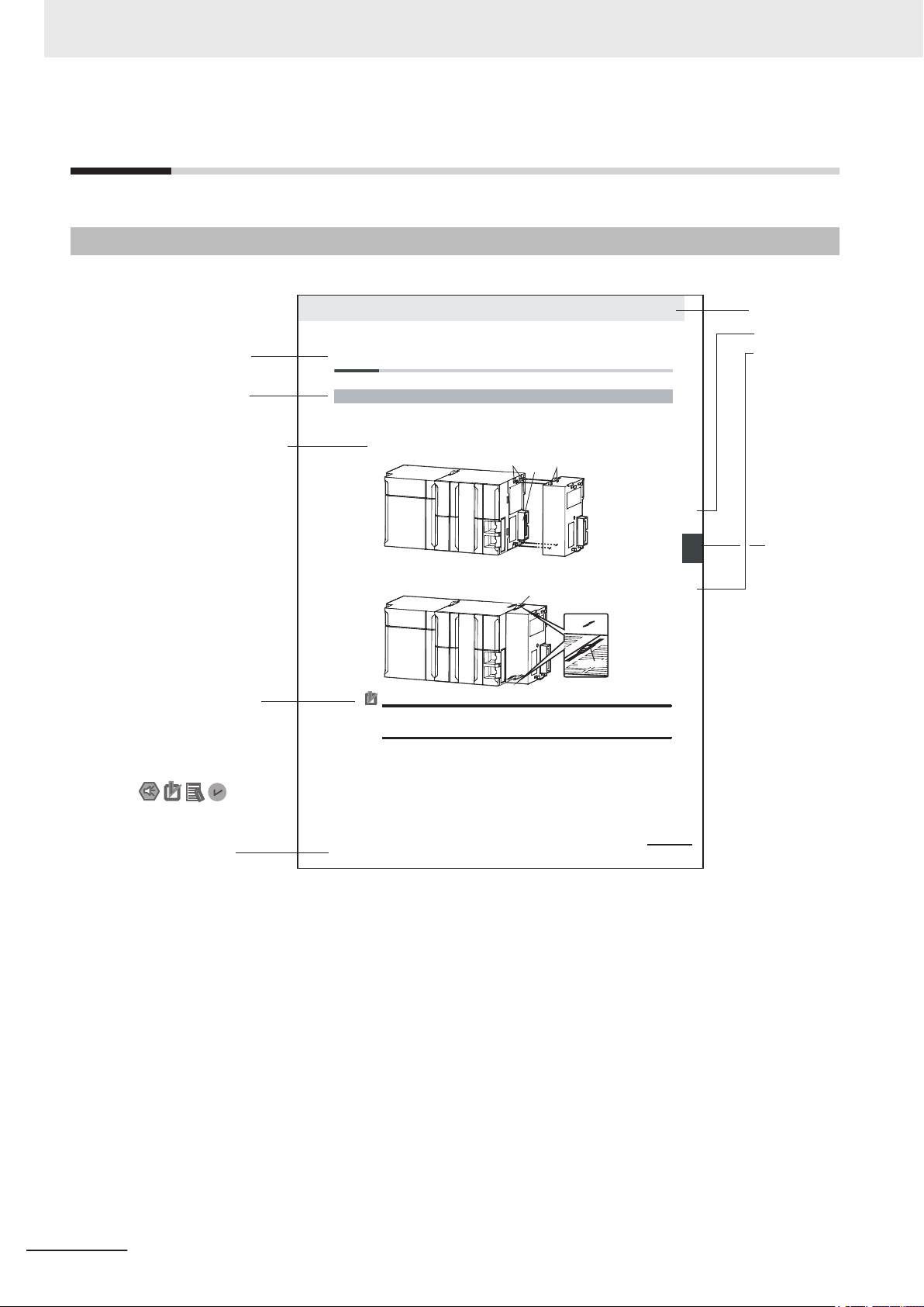
4-3 Mounting Units
The Units that make up an NJ-series Controller can be connected simply by pressing the Units together
and locking the sliders by moving them toward the back of the Units. The End Cover is connected in the
same way to the Unit on the far right side of the Controller.
1 Join the Units so that the connectors fit exactly.
2 The yellow sliders at the top and bottom of each Unit lock the Units together. Move the sliders
toward the back of the Units as shown below until they click into place.
Precautions for Correct UsePrecautions for Correct Use
4-3-1 Connecting Controller Components
Connector
Hook
Hook holes
Slider
Lock
Release
Move the sliders toward the back
until they lock into place.
Level 1 heading
Level 2 heading
Level 3 heading
Level 2 heading
A step in a procedure
Manual name
Special information
Level 3 heading
Page tab
Gives the current
headings.
Indicates a procedure.
Icons indicate
precautions, additional
information, or reference
information.
Gives the number
of the main section.
The sliders on the tops and bottoms of the Power Supply Unit, CPU Unit, I/O Units, Special I/O
Units, and CPU Bus Units must be completely locked (until they click into place) after connecting
the adjacent Unit connectors.
Manual Structure
Manual Structure
Page Structure
The following page structure is used in this manual.
Note This illustration is provided only as a sample. It may not literally appear in this manual.
4
FHV Series Smart Camera Setup Manual (Z408-E1)
Page 7

Special Information
Special information in this manual is classified as follows:
Precautions for Safe Use
Precautions on what to do and what not to do to ensure safe usage of the product.
Precautions for Correct Use
Precautions on what to do and what not to do to ensure proper operation and performance.
Additional Information
Additional information to read as required.
This information is provided to increase understanding or make operation easier.
Manual Structure
FHV Series Smart Camera Setup Manual (Z408-E1)
5
Page 8

6
FHV Series Smart Camera Setup Manual (Z408-E1)
Page 9

CONTENTS
Introduction .............................................................................................................. 1
Intended Audience...........................................................................................................................................1
Applicable Products ......................................................................................................................................... 1
Relevant Manuals..................................................................................................... 2
Manual Structure...................................................................................................... 4
Page Structure.................................................................................................................................................4
Special Information .......................................................................................................................................... 5
................................................................................................................................... 6
Sections in This Manual ........................................................................................ 29
Terms and Conditions Agreement........................................................................ 10
Warranty, Limitations of Liability ....................................................................................................................10
Application Considerations ............................................................................................................................11
Disclaimers ....................................................................................................................................................11
CONTENTS
Safety Precautions................................................................................................. 13
Symbols and the Meanings for Safety Precautions Described in This Manual .............................................13
Meanings of Alert Symbols ............................................................................................................................ 13
Warning..........................................................................................................................................................14
Precautions for Safe Use ...................................................................................... 15
Condition of the Fitness of OMRON Products ............................................................................................... 15
Installation Environment ................................................................................................................................15
Power Supply and Wiring ..............................................................................................................................15
Mounting ........................................................................................................................................................ 16
Others ............................................................................................................................................................ 17
Precautions for Correct Use ................................................................................. 18
Installation Location ....................................................................................................................................... 18
Power Supply, Connection, and Wiring..........................................................................................................18
Maintenance ..................................................................................................................................................19
Beam .............................................................................................................................................................19
Image Sensor ................................................................................................................................................19
Communications with Upper Equipment........................................................................................................ 19
Failsafe Measures .........................................................................................................................................20
Warm-up ........................................................................................................................................................ 20
Camera Installation........................................................................................................................................20
Others ............................................................................................................................................................ 20
LED Safety..................................................................................................................................................... 21
Regulations and Standards .................................................................................. 22
Using Product Outside Japan ........................................................................................................................ 22
Conformance to KC Standards......................................................................................................................22
Conformance to EC/EU Directives ................................................................................................................22
Related Manuals..................................................................................................... 23
Terminology............................................................................................................ 24
Revision History..................................................................................................... 28
FHV Series Smart Camera Setup Manual (Z408-E1)
7
Page 10

CONTENTS
Section 1 Confirm the Package
1-1 Smart Camera.......................................................................................................................1 - 2
1-1-1 FHV7H-□□□□□-C Series ...........................................................................................................1 - 2
1-1-2 FHV7H-□□□□□-S□□ Series .......................................................................................................1 - 2
1-1-3 FHV7H-□□□□□-S□□-□□ Series..................................................................................................1 - 3
1-2 Sold Separately ....................................................................................................................1 - 4
1-2-1 Cables .......................................................................................................................................1 - 4
1-2-2 Modules.....................................................................................................................................1 - 5
1-2-3 Accessories...............................................................................................................................1 - 6
1-2-4 Lighting and Lighting Controller ................................................................................................1 - 8
1-2-5 Software ....................................................................................................................................1 - 8
Section 2 Overview of FHV Series
2-1 Overview of System.............................................................................................................2 - 2
2-1-1 Basic System of Measurement .................................................................................................2 - 2
2-2 Flow of Use Procedure ........................................................................................................2 - 7
Section 3 Configuration
3-1 Smart Camera.......................................................................................................................3 - 2
3-1-1 FHV Series................................................................................................................................3 - 2
3-2 Cables .................................................................................................................................3 - 10
3-2-1 I/O Cables ...............................................................................................................................3 - 10
3-2-2 Ethernet Cables ......................................................................................................................3 - 13
3-3 Lens Modules .....................................................................................................................3 - 15
3-3-1 Specifications ..........................................................................................................................3 - 15
3-3-2 Meaning of Optical Chart ........................................................................................................3 - 17
3-4 C Mount Lenses .................................................................................................................3 - 20
3-4-1 Specifications ..........................................................................................................................3 - 20
3-4-2 Meaning of Optical Chart ........................................................................................................3 - 30
3-5 Lighting Modules ...............................................................................................................3 - 37
3-5-1 Specifications ..........................................................................................................................3 - 37
3-5-2 Dimensions .............................................................................................................................3 - 38
3-6 Optical Filters .....................................................................................................................3 - 39
3-6-1 Specifications ..........................................................................................................................3 - 39
3-6-2 Dimensions .............................................................................................................................3 - 39
3-7 Waterproof Hoods..............................................................................................................3 - 41
3-7-1 Specifications ..........................................................................................................................3 - 41
3-7-2 Dimensions .............................................................................................................................3 - 42
3-8 Mounting Fixtures..............................................................................................................3 - 46
3-8-1 Specfications...........................................................................................................................3 - 46
3-8-2 Dimensions .............................................................................................................................3 - 46
3-9 Software..............................................................................................................................3 - 48
3-9-1 Remote Operation Tool ...........................................................................................................3 - 48
3-9-2 Simulation Software ................................................................................................................3 - 48
Section 4 Handling and Installation Environment
4-1 Warning.................................................................................................................................4 - 2
8
FHV Series Smart Camera Setup Manual (Z408-E1)
Page 11

Section 5 Installation
5-1 Assembling Equipment ....................................................................................................... 5 - 2
5-1-1 C Mount Lens / IP40 Configuration ...........................................................................................5 - 2
5-1-2 C Mount Lens / IP67 Configuration ...........................................................................................5 - 3
5-1-3 Lens Module / IP40 Configuration.............................................................................................5 - 5
5-1-4 Lens Module / IP67 Configuration.............................................................................................5 - 8
5-1-5 Lens Module / Internal Lighting / IP67 Configuration ..............................................................5 - 10
5-2 Installing the Smart Camera .............................................................................................5 - 14
5-2-1 How to Connect.......................................................................................................................5 - 14
5-2-2 When Connecting the Smart Camera to a Lighting Controller ................................................5 - 18
Section 6 Power Supply and I/O Interface
6-1 When Turning Power ON and OFF .....................................................................................6 - 2
6-2 Fail-safe Measures...............................................................................................................6 - 4
6-3 Precautions for I/O Interface...............................................................................................6 - 5
6-4 I/O Cable Interface (Power Supply, I/O, RS-232C).............................................................6 - 6
6-4-1 Recommended Power Supply for FHV Series ..........................................................................6 - 6
6-4-2 Cables .......................................................................................................................................6 - 7
6-4-3 Pin Layout .................................................................................................................................6 - 8
6-4-4 Interface Specifications .............................................................................................................6 - 9
6-4-5 I/O Interface Input / Output Circuit Diagram............................................................................6 - 12
6-4-6 RS-232C Interface ..................................................................................................................6 - 14
6-5 Ethernet Interface ..............................................................................................................6 - 15
6-5-1 Cables .....................................................................................................................................6 - 16
6-5-2 Pin Layout ...............................................................................................................................6 - 17
6-6 Inserting and Removing the MicroSD Card.....................................................................6 - 18
6-6-1 How to Insert / Remove the MicroSD Card .............................................................................6 - 18
CONTENTS
Section 7 Software Setup
7-1 Setting up the Software.......................................................................................................7 - 2
7-1-1 Recommended Operational Environment .................................................................................7 - 2
7-1-2 Installation .................................................................................................................................7 - 2
7-1-3 Windows....................................................................................................................................7 - 3
7-1-4 Use Procedures ........................................................................................................................7 - 4
7-2 Operating the Smart Camera Remotely [Remote Operation Tool] ................................7 - 10
7-2-1 Summary.................................................................................................................................7 - 10
7-2-2 Environment Settings .............................................................................................................. 7 - 11
7-2-3 Network Settings for the Remote Operation PC .....................................................................7 - 11
7-2-4 Network Settings for the Smart Camera .................................................................................7 - 12
7-2-5 Network Settings for the Smart Camera with Remote Operation Tool ....................................7 - 14
7-2-6 Launching the Remote Operation ...........................................................................................7 - 14
7-2-7 Terminating the Remote Operation .........................................................................................7 - 17
7-3 Using the Simulation Software [Simulation Software] ................................................... 7 - 18
7-3-1 Introduction .............................................................................................................................7 - 18
7-3-2 Available Image Formats.........................................................................................................7 - 18
7-3-3 Operational Precautions..........................................................................................................7 - 18
Index
FHV Series Smart Camera Setup Manual (Z408-E1)
9
Page 12

Terms and Conditions Agreement
Terms and Conditions Agreement
Warranty, Limitations of Liability
Warranties
Exclusive Warranty
l
Omron’s exclusive warranty is that the Products will be free from defects in materials and work-
manship for a period of twelve months from the date of sale by Omron (or such other period ex-
pressed in writing by Omron). Omron disclaims all other warranties, express or implied.
Limitations
l
OMRON MAKES NO WARRANTY OR REPRESENTATION, EXPRESS OR IMPLIED, ABOUT
NON-INFRINGEMENT, MERCHANTABILITY OR FITNESS FOR A PARTICULAR PURPOSE OF
THE PRODUCTS. BUYER ACKNOWLEDGES THAT IT ALONE HAS DETERMINED THAT THE
PRODUCTS WILL SUITABLY MEET THE REQUIREMENTS OF THEIR INTENDED USE.
Omron further disclaims all warranties and responsibility of any type for claims or expenses based
on infringement by the Products or otherwise of any intellectual property right.
Buyer Remedy
l
Omron’s sole obligation hereunder shall be, at Omron’s election, to (i) replace (in the form originally
shipped with Buyer responsible for labor charges for removal or replacement thereof) the non-com-
plying Product, (ii) repair the non-complying Product, or (iii) repay or credit Buyer an amount equal
to the purchase price of the non-complying Product; provided that in no event shall Omron be re-
sponsible for warranty, repair, indemnity or any other claims or expenses regarding the Products
unless Omron’s analysis confirms that the Products were properly handled, stored, installed and
maintained and not subject to contamination, abuse, misuse or inappropriate modification. Return
of any Products by Buyer must be approved in writing by Omron before shipment. Omron Compa-
nies shall not be liable for the suitability or unsuitability or the results from the use of Products in
combination with any electrical or electronic components, circuits, system assemblies or any other
materials or substances or environments. Any advice, recommendations or information given orally
or in writing, are not to be construed as an amendment or addition to the above warranty.
10
See http://www.omron.com/global/ or contact your Omron representative for published information.
Limitation on Liability; Etc
OMRON COMPANIES SHALL NOT BE LIABLE FOR SPECIAL, INDIRECT, INCIDENTAL, OR CON-
SEQUENTIAL DAMAGES, LOSS OF PROFITS OR PRODUCTION OR COMMERCIAL LOSS IN ANY
FHV Series Smart Camera Setup Manual (Z408-E1)
Page 13

WAY CONNECTED WITH THE PRODUCTS, WHETHER SUCH CLAIM IS BASED IN CONTRACT,
WARRANTY, NEGLIGENCE OR STRICT LIABILITY.
Further, in no event shall liability of Omron Companies exceed the individual price of the Product on
which liability is asserted.
Application Considerations
Suitability of Use
Omron Companies shall not be responsible for conformity with any standards, codes or regulations
which apply to the combination of the Product in the Buyer’s application or use of the Product. At Buy-
er’s request, Omron will provide applicable third party certification documents identifying ratings and
limitations of use which apply to the Product. This information by itself is not sufficient for a complete
determination of the suitability of the Product in combination with the end product, machine, system, or
other application or use. Buyer shall be solely responsible for determining appropriateness of the par-
ticular Product with respect to Buyer’s application, product or system. Buyer shall take application re-
sponsibility in all cases.
Terms and Conditions Agreement
NEVER USE THE PRODUCT FOR AN APPLICATION INVOLVING SERIOUS RISK TO LIFE OR
PROPERTY OR IN LARGE QUANTITIES WITHOUT ENSURING THAT THE SYSTEM AS A WHOLE
HAS BEEN DESIGNED TO ADDRESS THE RISKS, AND THAT THE OMRON PRODUCT(S) IS
PROPERLY RATED AND INSTALLED FOR THE INTENDED USE WITHIN THE OVERALL EQUIP-
MENT OR SYSTEM.
Programmable Products
Omron Companies shall not be responsible for the user’s programming of a programmable Product, or
any consequence thereof.
Disclaimers
Performance Data
Data presented in Omron Company websites, catalogs and other materials is provided as a guide for
the user in determining suitability and does not constitute a warranty. It may represent the result of
Omron’s test conditions, and the user must correlate it to actual application requirements. Actual per-
formance is subject to the Omron’s Warranty and Limitations of Liability.
Change in Specifications
Product specifications and accessories may be changed at any time based on improvements and oth-
er reasons. It is our practice to change part numbers when published ratings or features are changed,
or when significant construction changes are made. However, some specifications of the Product may
FHV Series Smart Camera Setup Manual (Z408-E1)
11
Page 14

Terms and Conditions Agreement
be changed without any notice. When in doubt, special part numbers may be assigned to fix or estab-
lish key specifications for your application. Please consult with your Omron’s representative at any
time to confirm actual specifications of purchased Product.
Errors and Omissions
Information presented by Omron Companies has been checked and is believed to be accurate; how-
ever, no responsibility is assumed for clerical, typographical or proofreading errors or omissions.
12
FHV Series Smart Camera Setup Manual (Z408-E1)
Page 15
Safety Precautions
Safety Precautions
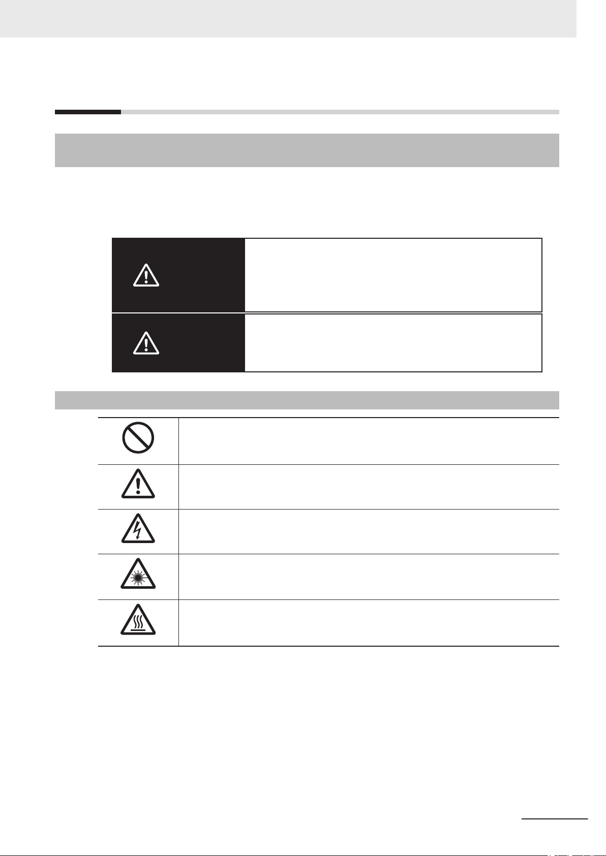
Symbols and the Meanings for Safety Precautions Described in This Manual
The following notation is used in this manual to provide precautions required to ensure safe usage of a
Sensor Controller. The safety precautions that are provided are extremely important to safety.
Always read and heed the information provided in all safety precautions.
The following notation is used.
Indicates a potentially hazardous situation which, if not avoid-
WARNING
ed, will result in minor or moderate injury, or may result in seri-
ous injury or death.
Additionally there may be significant property damage.
Caution
Meanings of Alert Symbols
General Prohibition
Indicates general prohibitions, including warnings, for which there is no specific
symbol
General Caution
Indicates general cautions, including warnings, for which there is no specific symbol.
Electrical Hazard
Indicates the possible danger of electric shock under specific conditions.
LED light Hazard
Indicates the possible danger of LED radiation or light.
High Temperature Caution
Indicates the possible danger of injury by high temperature under specific conditions.
Indicates a potentially hazardous situation which, if not avoid-
ed, may result in minor or moderate injury or in property dam-
age.
FHV Series Smart Camera Setup Manual (Z408-E1)
13
Page 16
Safety Precautions
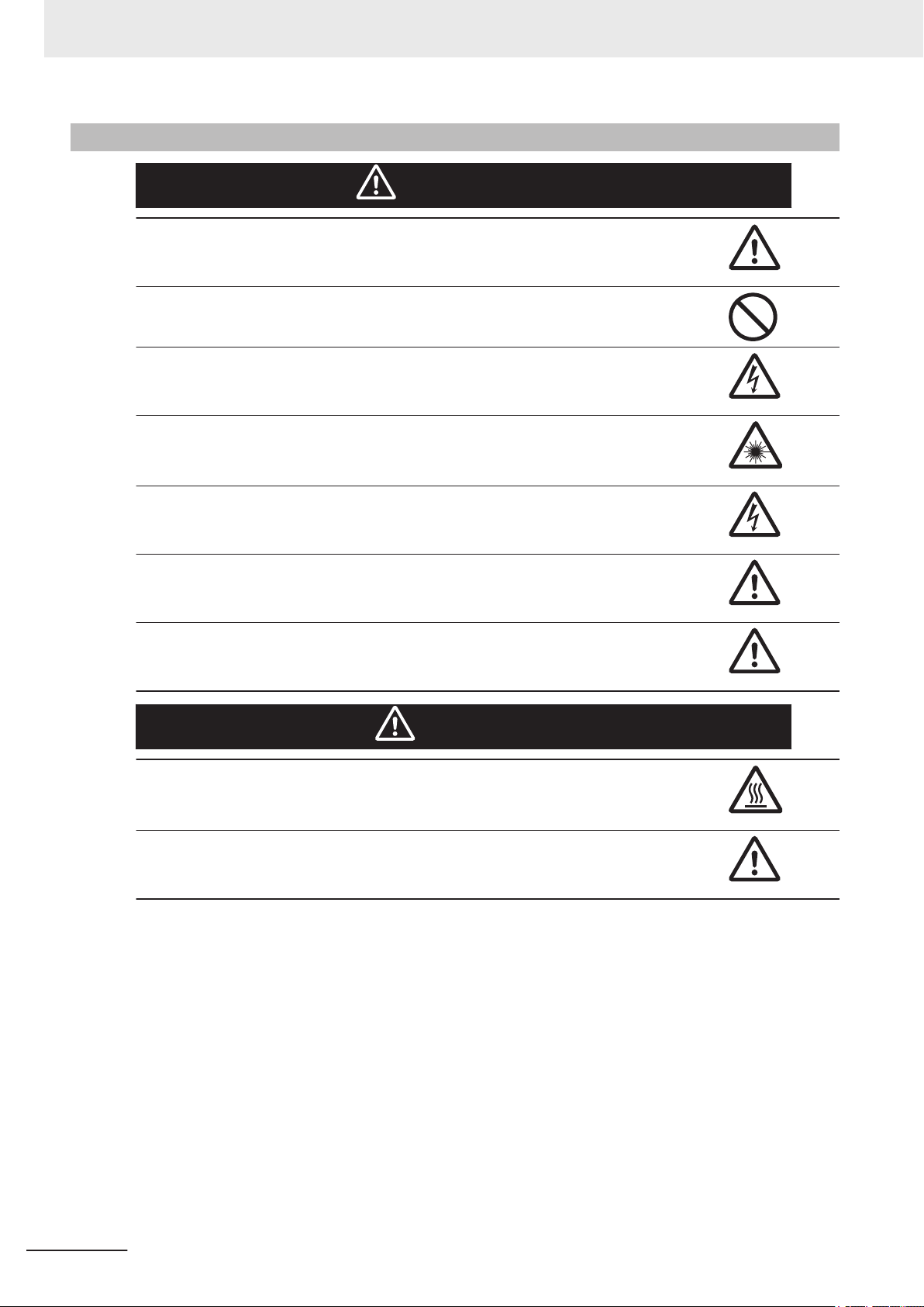
Warning
This product must be used according to this manual and Instruction Sheet.
Failure to observe this may result in the impairment of functions and performance of the
product.
This product is not designed or rated for ensuring the safety of persons.
Do not use it for such purposes.
Never connect the AC power supply with this product. When the AC power supply is connected, it causes the electric shock and a fire.
If you keep watching the LED light, it may have an adverse effect on the eyes, do not stare
directly into the light emitted from the LED. If a specular object is used, take care not to allow
reflected light to enter your eyes.
WARNING
Do not touch the terminals while the power supply is ON.
Doing so may result in electrical shock.
Please take external safety measures so that the system as a whole should be on the safe
side even if a failure of a smart camera or an error due to an external factor occurred. An
abnormal operation may result in serious accident.
Please take fail-safe measures on your side in preparation for an abnormal signal due to signal conductor disconnection and/or momentary power interruption.
An abnormal operation may result in a serious accident.
Caution
Danger of burns. Do not touch the case while the power is ON or just after power is turned
OFF, since it remains extremely hot.
When mounting the lighting module, lens module, and covers, make sure that the screws are
tightened securely. If not, the product may break or malfunction, or injury may result.
14
FHV Series Smart Camera Setup Manual (Z408-E1)
Page 17

Precautions for Safe Use
Condition of the Fitness of OMRON Products
• Please do not use this product to directly or indirectly use to detect the human body for the purpose
of ensuring the safety. In the same application, please use the safety sensor that is published on our
sensor catalog.
• Omron products are designed and manufactured as general-purpose products for use in general in-
dustrial applications. They are not intended to be used in the following critical applications. If you are
using Omron products in the following applications, Omron shall not provide any warranty for such
Omron products, unless otherwise specifically agreed or unless the specific applications are intend-
ed by Omron.
a) Applications with stringent safety requirements, including but not limited to nuclear power control
equipment, combustion equipment, aerospace equipment, railway equipment, elevator/lift equip-
ment, amusement park equipment, medical equipment, safety devices and other applications
that could cause danger/harm to people's body and life.
b) Applications that require high reliability, including but not limited to supply systems for gas, water
and electricity, etc., 24 hour continuous operating systems, financial settlement systems and oth-
er applications that handle rights and property.
c) Applications under severe condition or in severe environment, including but not limited to out-
door equipment, equipment exposed to chemical contamination, equipment exposed to electro-
magnetic interference and equipment exposed to vibration and shocks.
d) Applications under conditions and environment not described in specifications.
Precautions for Safe Use
(1) In addition to the applications listed from (a) to (d) above, Omron products (see definition) are not
intended for use in vehicles designed human transport (including two wheel vehicles). Please do
NOT use Omron products for vehicles designed human transport. Please contact the Omron
sales staff for information on our automotive line of products.
(2) The above is part of the Terms and Conditions Agreement. Please use carefully read the contents
of the guarantee and disclaimers described in our latest version of the catalog, data sheets and
manuals.
Installation Environment
• Do not use the product in areas where flammable or explosive gases are present.
• Do not install the product close to high-voltage devices and power devices in order to secure the
safety of operation and maintenance.
• Do not install the product to a place where vibrations and/or impacts are expected.
• Do not install the product near to a device causing noises. if the product is installed in a noisy envi-
ronment and operational errors are caused, be sure to take shielding measures.
Power Supply and Wiring
• Make sure to use the product with the power supply voltage specified. If a DC voltage exceeding the
rating or an AC voltage is applied, the circuit parts may be burnt or exploded.
• Do not connect the power supply with polarity reversed.
FHV Series Smart Camera Setup Manual (Z408-E1)
15
Page 18

Precautions for Safe Use
• Use a DC power supply with safety measures against high-voltage spikes (safety extra low-voltage
circuits on the secondary side).
• Use an independent power source for this product. Do not use a shared power source.
• Never apply more than the rated voltage or AC power supply to this product. It may cause malfunc-
tion.
• The recommended power supplies are as follows:
- When attaching the lighting module, use S8VK-G12024 (OMRON) or S8VS-12024 (OMRON).
- When not attaching the lighting module, use S8VK-G06024 (OMRON) or S8VS-06024 (OMRON).
• Wire high-voltage cables or power cables separately from the cables of this product. If the same ca-
ble or duct is used, the product may receive induction and it may cause malfunctioning or breakage.
• Do not short-circuit load on the open collector output.
• Apply load not exceeding the rating.
• When wiring, put a crimp terminal of the specified size. Do not connect wires simply twisted together
to the power supply or terminal block directly.
• If using an I/O cable 20 m long, confirm that the power supply output is 24 VDC or higher. If it is
lower than 24 VDC, the product does not operate.
• Cut off unnecessary signal wires so that they do not contact any other signal wires.
• After wiring the cables, confirm if the power supply is appropriate, if there is miswiring such as short-
circuit of load, if the load current is appropriate, and if FG is connected appropriately. Otherwise, the
product may be broken due to miswiring etc.
• Take enough safety measures such as a failsafe circuit before using the product.
• Be sure to apply Class D grounding (100Ω or lower grounding resistance) to the case of the smart
camera and the ground wire of the I/O cable.
• Do not share the ground wire with some other devices or connect it to the beam of the building. The
product may be adversely affected.
• Determine the contact point as near as possible to shorten the ground wire as much as possible.
The product may be adversely affected.
Mounting
• When doing the following, be sure to turn OFF the power of the smart camera main unit or connect-
ed peripheral devices. Not doing so leads to a product failure.
- Cable connection and wiring
- Connector mounting/removal
- Lighting module mounting/removal
- Lens module mounting/removal
• Tighten the mounting screws securely using the defined torque and order described in the Setup
Manual.
• Mount the lens module in the correct direction. Mounting it in the wrong direction may cause mal-
function of the device or injury.
• After removing the cable, be sure to put the connector cap. If the connector cap is not put, the prod-
uct may malfunction or be broken due to entering of foreign materials.
• For the component with a lock mechanism, be sure to confirm that it is locked before using the prod-
uct.
• Do not apply torsional stress to the cable. Doing so may cause cable breakage.
• Secure the minimum bending radius of the cable. If it cannot be secured, the cable may be broken.
• Assemble as avoiding the waterproof packings and harnesses from being caught by the case, etc.
16
FHV Series Smart Camera Setup Manual (Z408-E1)
Page 19

• Do not use any damaged waterproof packings and light shielding sheet or assemble the product
• Mount the lens module and lighting model in the correct direction. Mounting them in the wrong direc-
• Do not touch the lens or image sensor with bare hands. Doing so may lead to malfunctioning or
Others
• Use only the dedicated cable (FHV-VN/FHV-VD), camera-mount lighting controller (FL-TCC/
• If anything abnormal occurs, for example, strange smell/sound is detected, the main unit gets very
• Do not disassemble, deform by pressurizing, incinerate, repair, or alter this product.
• When disposing of the product, treat as industrial waste.
• Do not drop the product or expose it to abnormal vibration or impact. Doing so may lead to product
• If using the measurement result of the smart camera to operate the stage or robot (output of axis
• The waterproof packing and light shielding sheet are rubber products. Avoid storing them in a loca-
Precautions for Safe Use
with foreign materials attached to or caught in.
tion may cause broken or malfunction of the device, or injury.
breakage.
Assemble the lens and image sensor with a correct combination. if not, malfunction may result.
FLV-TCC), lighting module (FHV-LTM-), and lens module (FHV-LEM-). Otherwise, the product
may malfunction or be broken.
hot, or a smoke comes, stop using the product, turn OFF the product, and consult OMRON’s branch
or sales office.
failure.
moving distance by calibration and alignment measurement), be sure to take failsafe measures ex-
ternally.
tion where rubber deteriorates.
FHV Series Smart Camera Setup Manual (Z408-E1)
17
Page 20

Precautions for Correct Use
Precautions for Correct Use
Installation Location
In order to prevent the product from becoming inoperable or malfunction, and to prevent other adverse
effects to the performance or equipment, please observe the following.
• A location where the ambient temperature does not exceed the rated range (operating: 0 to 40°C,
storage: -25 to 65°C).
• A location where the temperature does not vary sharply (condensation occurs).
• A location where relative temperature does not exceed a range of 35-85%RH.
• A location not exposed to corrosive gases or combustible gases.
• A location not exposed to dust, salt, or metal powder.
• A location not exposed to direct vibration or impact.
• A location not exposed to strong disturbance light (laser light, arc welding light, or ultraviolet light).
• A location not near a heating appliance or exposed to direct sunlight.
• A location not exposed to mist of water, oil, or chemicals or misty atmosphere.
• A location not exposed to strong magnetic/electric fields.
• A location not near a high-voltage device or power device
• A location where rubber quality is not deteriorated.
Power Supply, Connection, and Wiring
• If using a commercially available switching regulator, earth the frame ground terminal.
• If the power supply line has surge, connect a surge absorber according to the operational environ-
ment to use the product.
• After wiring the cables, confirm if the power supply is appropriate, if there is miswiring such as short-
circuit of load, or if the load current is appropriate. Otherwise, the product may be broken due to
miswiring etc.
• Do not put load on the cables and connectors before wiring them.
• Do not turn OFF the power supply while data are being saved in the smart camera. Otherwise, data
on the memory is broken, so the product does not operate normally when started up next time.
• When turning OFF the power, confirm that data have been saved completely before starting opera-
tions.
- When data are saved by operating the sensor controller, the saving process must have been com-
pleted and the following user operations must be possible.
- When data are saved using communication commands, processing of the applicable commands
must have been completed and the busy state is OFF.
• If contacting a terminal or a signal cable inside the connector, use a wrist strap to take antistatic
measures to prevent breakage due to static electricity.
• If removing the microSD card, confirm that data are not being read or written before removing it.
• Do not insert the microSD card inversely, obliquely, or as twisting it.
• While data are being read in or written to the microSD card, the SD ACCESS LED on the Smart
Camera main unit is turned on for a while. Remove the card after confirming that the LED is com-
pletely turned off.
• Except when inserting or removing the microSD card, put the cover of the microSD card inserting
connector and screw it up before using the product.
18
FHV Series Smart Camera Setup Manual (Z408-E1)
Page 21

• When a message indicating that processing is being executed is displayed on the screen, do not
turn OFF the power. Otherwise, data on the memory is broken, so the product does not operate nor-
mally when started up again.
• Do not use the product in environments subject to water droplets when an external lighting is con-
nected. The main unit may be broken.
• The RS-232C communication standard defines the maximum cable length as 15 m. Implement this
communication using an I/O cable 2/3/5/10 m long.
• When connecting cables, align terminals and connect them straightly. If not, the terminals bent and
may cause malfunction or unable to communicate normally.
Maintenance
• Turn OFF the power and confirm safety before starting maintenance.
• Remove dirt on the lens using the special cloth for lens or an air brush.
• If a large dust attaches to the image sensor, use the blower brush (for the camera lens) to blow it off.
Do not blow it off with your exhaled air.
• Do not use thinner, alcohol, benzene, acetone, or kerosene to clean his product.
• When the lens or lens module is not being mounted, be sure to attach the C mount cap to the lens
mounting part. If a dust attached to the image sensor, the product may sense incorrectly or be bro-
ken.
• Wipe off dirt on this product with a soft cloth gently.
• Be sure to put the cap/cover onto the connector not used. Otherwise, the product may malfunction
or get out of order due to entering of foreign materials.
Precautions for Correct Use
Beam
• The beam center may vary product by product. When mounting this module, be sure to confirm the
center position of the video on the monitor.
The beam center of this product may vary over a couple of pixels due to the variation of ambient
temperature because of the material characteristics.
• Select the model by confirming the field of view and camera installation distance on the optical dia-
gram. In addition, the field of view may vary product by product.
When mounting this product, be sure to confirm video using the monitor.
Image Sensor
• For this product, a line may appear depending on the measurement condition or sensitivity because
of the specification of the image sensor.
However, this is not a fault or failure of the product. In addition, although there may be multiple de-
fective pixels, this is not a fault or failure of the product. Use the product as confirming the actual
image.
Communications with Upper Equipment
• Implement communications with upper equipment after confirming that this product has been started
up. In addition, when this product is being started up, unstable signals may be issued by the upper
FHV Series Smart Camera Setup Manual (Z408-E1)
19
Page 22

Precautions for Correct Use
interface. In the initial operation, take action such as clearing the receiving buffer of the equipment
used.
Failsafe Measures
• When operating a stage or robot using measurement results of the Smart Camera (axis moving dis-
tance output by the calibration or alignment measurement), take measures as follows: Be sure to
operate the stage or robot after confirming the measurement result data on the stage or robot side
that the data are within the movable range of the stage or robot.
Warm-up
• Turn ON the power and wait for 60 minutes or more before conducting precise inspection. The cir-
cuit is not stable directly after the power is turned ON, so brightness may vary gradually.
Camera Installation
• In an environment exposed to high humidity and sharp temperature fluctuation, the inside of the
lighting cover may become cloudy in rare cases. If it becomes cloudy, remove the lighting cover and
wipe off the inside with a soft cloth.
• If installing smart camera main units side by side, secure a space of 30 mm or more wide between
them.
Others
• For better heat radiation, use the separately sold fitting (FHV-XMT-7) or mount the product to the
metal frame (recommended size: 100×110 mm or more and thickness: 10 mm or more).
• Do not assemble the lighting module or waterproof hood in a hot and humid environment. Other-
wise, condensation may occur. If it becomes cloudy, remove the lighting cover and wipe off the
moisture with an absorbent, but soft cloth so as not to damage the product.
• There are two types of polarizing filters: FHV-XPL (for visible light) and FHV-XPL-IR (for both visible
and infrared lights). Use the appropriate option according to the illumination light source.
• If switching the focus for a long period of time continuously except when installing and adjusting the
product, performance may be degraded due to heat generation or abrasion of inner parts.
• When the lens module is mounted to the product, the specificatins of vibration tolerance are
changed.
• Do not touch the lens module after it is mounted. Otherwise, it may be broken.
• If using this product without attaching the lighting module in an environment needing waterproof, use
waterproof hood FHV-XHD series.
• Operate the product by using Calculation and Branch processing items on the Smart Camera side
additionally and creating a check flow, for example, if the stage or robot is within a range of -xxxxx to
xxxxx from its movable range, data are not output to outside.
• The lighting module and lens module are fixed to the smart camera with dropout preventing screws.
Do not remve them from the product.
• When turning on the FHV series, the date/time settings always returns to the default. Therefore, you
need to re-set the date/time with an operation or a communication command every time at startup.
20
FHV Series Smart Camera Setup Manual (Z408-E1)
Page 23
For details of communication commands, refer to each communication command in the Vision
System FH/FZ5 Series User's Manual for Communications Settings (Cat. No.Z342).
LED Safety
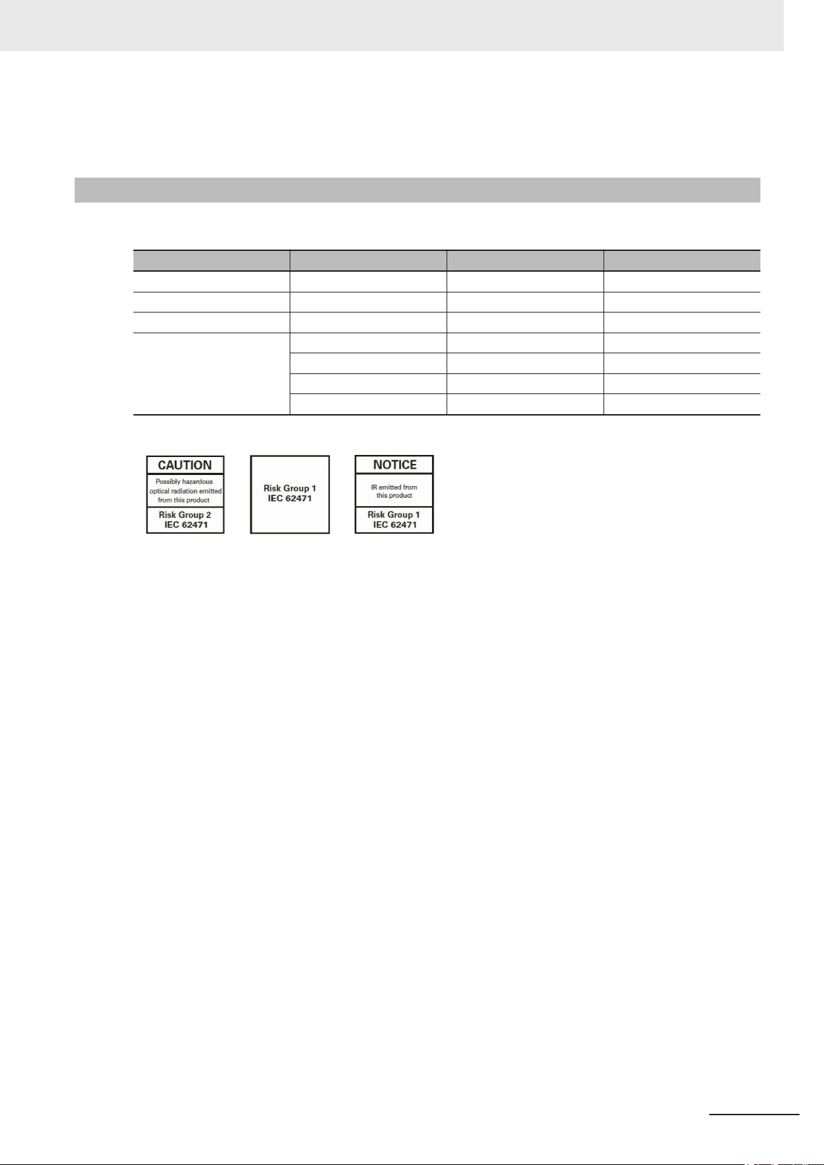
This product is classified into the following risk groups by IEC62471.
FHV-LTM-W White Risk group 2 A
FHV-LTM-R Red Risk group 1 B
FHV-LTM-IR Infrared light Risk group 1 C
FHV-LTM-MC
Precautions for Correct Use
Model Color LED safety Display
Red Risk group 1 B
Green Risk group 2 A
Blue Risk group 2 A
Infrared light Risk group 1 C
A B C
FHV Series Smart Camera Setup Manual (Z408-E1)
21
Page 24
Regulations and Standards
Regulations and Standards
Using Product Outside Japan
If you export (or provide a non-resident with) this product or a part of this product that falls under the
category of goods (or technologies) specified by the Foreign Exchange and Foreign Trade Control
Law as those which require permission or approval for export, you must obtain permission or approval
or service transaction permission) pursuant to the law.
Conformance to KC Standards
Observe the following precaution if you use this product in Korea.
• Class A Device (Broadcasting Communications Device for Office Use)
This device obtained EMC registration for office use (Class A), and it is intended to be used in pla-
ces other than homes. Sellers and/or users need to take note of this.
Conformance to EC/EU Directives
The product is compliant with the standards below:
• EU Directive 2014/30/EU (After April 20 2016)/EU EN61326-1
Electromagnetic environment : Industrial electromagnetic environment (EN/IEC 61326-1 Table 2)
• This product complies with EC/EU Directives. EMC-related performance of the OMRON devices that
comply with EC/EU Directives will vary depending on the configuration, wiring, and other conditions
of the equipment or control panel on which the OMRON devices are installed.
• The customer must, therefore, perform the final check to confirm that devices and the overall ma-
chine conform to EMC standards.
22
FHV Series Smart Camera Setup Manual (Z408-E1)
Page 25

Related Manuals
The followings are the manuals related to this manual. Use these manuals for reference.
Name of Manual Man. No.. Model Purpose Contents
Smart Camera
FHV Instruction Sheet
Smart Camera
Lighting Module
FHV-LTM Instruction Sheet
Smart Camera Lens Module
FHV-LEM-S Instruction
Sheet
FHV Series
i-Smart Camera
Setup Manual
Vision System
FH/FHV/FZ5 Series
User's Manual
Vision System
FH/FHV/FZ5 Series Processing Item Function Reference Manual
Vision System
FH/FHV/FZ5 Series
User's manual for Communications Settings
3129404-0
3129276-4
3128622-5
Z408
Z365
Z341 When User confirm
Z342 When User confirm
FHV7£-££££-C
FHV-LTM££
FHV-LEM-S££
FHV7£-££££-C
FHV7£-££££-S-££
FHV7£-££££-S-££-££
FH-1£££
FH-1£££-££
FH-2£££
FH-2£££-££
FH-3£££
FH-3£££-££
FH-5£££
FH-5£££-££
FH-L£££
FH-L£££-££
FHV7£-££££-C
FHV7£-££££-S-££
FHV7£-££££-S-££-££
FZ5-L35£
FZ5-L35£-££
FZ5-6££
FZ5-6££-££
FZ5-8££
FZ5-8££-££
FZ5-11££
FZ5-11££-££
FZ5-12££
FZ5-12££-££
To confirm the safety
and usage precautions of the Smart
Camera FHV7 series.
To confirm the safety
and usage precautions of the Smart
camera lighting module FHV-LTM.
To confirm the safety
and usage precautions of the Smart
camera lens module
FHV-LEM.
When User want to
know about the hardware specifications
or to setup the Smart
camera FHV series.
When User want to
know about the
FH/FHV/FZ5 series.
the details of each
processing items at
the create the measurement flow or operate it.
the setting of communication functions.
Describes the definitions of basic
terms, the meaning of signal words,
and precautions for correct use of
FHV7 series in the manual.
Describes the definitions of basic
terms, the meaning of signal words,
and precautions for correct use of
the lighting module FHV-LTM in the
manual.
Describes the definitions of basic
terms, the meaning of signal words,
and precautions for correct use of
the lens module FHV-LEM.
Describes FHV series specifications,
dimensions, part names, I/O information, installation information, and
wiring information.
Describes the soft functions, setup,
and operations to use FH/FHV/FZ5
series/
Describes the software functions,
settings, and operations for using
FH/FHV/FZ5 series.
Describes the functions, settings,
and communications methods for
communication between
FH/FHV/FZ5 series and PLCs.
The following communications protocol are described.
Parallel, PLC Link, EtherNet/IP,
EtherCAT, and Non-procedure.
Related Manuals
FHV Series Smart Camera Setup Manual (Z408-E1)
23
Page 26

Terminology
Terminology
Term Definition
FHV Series All FHV series model names.
Measurement flow (abbreviated as “flow”)
Measurement processing Executing processing items for inspections and measurements.
Measurement ID Measurement time: YYYY-MM-DD_HH-MM-SS-XXXX
Processing item Any of the individual items for vision inspections that are partitioned and packaged
Scene A unit for changing the measurement flow that consists of a combination of proc-
Processing unit (abbreviated as unit)
Measurement trigger A trigger for executing measurements.
Test measurement A measurement that is performed to manually test (check) measurements under
Single measurement A measurement that is executed only once in synchronization with the trigger input.
Continuous measurement Measurements are executed repeatedly and automatically without a trigger input.
A continuous flow of measurement processing. A measurement flow consists of a
scene created from a combination of processing items.
(YYYY: Calendar,, MM: Month, DD: Day, HH: Hour, MM: Minutes, SS: Second,
XXXX: Millisecond and Line number.)
• Example:
Measurement time: 11:10:25.500 AM, December 24, 2007 and Line 0, the measurement ID is "2007-12-24_11-10-25-5000".
so that they can be flexibly combined.
These include the Search, Position Compensation, and Fine Matching items.
Processing items can be classified for image input ([Input image]), inspection/
measurement ([Measurement]), image correction ([Compensate image]), inspection/measurement support ([Support measurement]), process branching ([Branch]),
results external output ([Output result]), resulting image display ([Display result]),
etc.
You can freely classify processing items to handle a wide range of applications.
A scene (i.e., a unit for changing the measurement flow) is created by registering
the processing items as units.
essing items.
Scene is used because of the correspondence to the scene (i.e., type of measurement object and inspection contents) where measurements are performed.
A scene is created for each measurement or measurement contents.
You can easily achieve a changeover simply by changing the scene when the
measurement
object or inspection content changes.
Normally you can set up to 128 scenes. If you need more than 128 scenes, you
can separate them into different groups or use the Conversion Scene Group Data
Tool to create a scene group that contains over 128 scenes.
A processing item that is registered in a scene.
Numbers are assigned to processing units in order from the top and they are executed in that order.
Processing items are registered for the processing units to create a scene (i.e., a
unit for changing the measurement flow).
With a parallel interface, the STEP signal is used. With a serial interface, an Execute One Measurement or a Start Continuous Measurement command is used.
the conditions that are set in the currently displayed scene.
Test measurements can be executed on an Adjustment Window. Processing is
completed inside the Controller and the measurement results are not normally output on an external interface.
However, you can select Output in Test measurement to output the measurement
results after executing measurements.
24
FHV Series Smart Camera Setup Manual (Z408-E1)
Page 27

Term Definition
Operation mode
• Double Speed Multi-input
A mode that processes the measurement flow for the first trigger and then processes the measurement flow in parallel for the second trigger to achieve a highspeed trigger input interval. It is used together with the multi-input function.
• Non-stop adjustment mode
A mode that allows you to adjust the flow and set parameters while performing
measurements.
The enables adjustments without stopping the line or stopping inspections.
• Standard
A logging mode that allows complete parallel processing of measurements and
logging.
Traditionally, logging was not possible while processing measurements. Either
measurements or logging had to be given priority and the other one had to wait.
With this mode, you can save the measurement images in external storage without affecting the transaction time.
Parallel processing (an
option for any of the
above operation modes)
Multi-input function A function that is used to consecutively and quickly input images.
Parallel processing splits part of the measurement flow into two or more tasks, and
processes each task in parallel to shorten the transaction time.
Processing items for parallel processing are used so that the user can specify the
required parallel processing.
It allows the next STEP signal to be acknowledged as soon as the image input
processing is completed. There is no need to wait for measurement processing to
be completed.
You can check whether image input processing has been completed with the status
of the READY signal. Even if the READY signal is ON when measurement processing is being executed, the next STEP signal can be acknowledged.
Terminology
FHV Series Smart Camera Setup Manual (Z408-E1)
25
Page 28
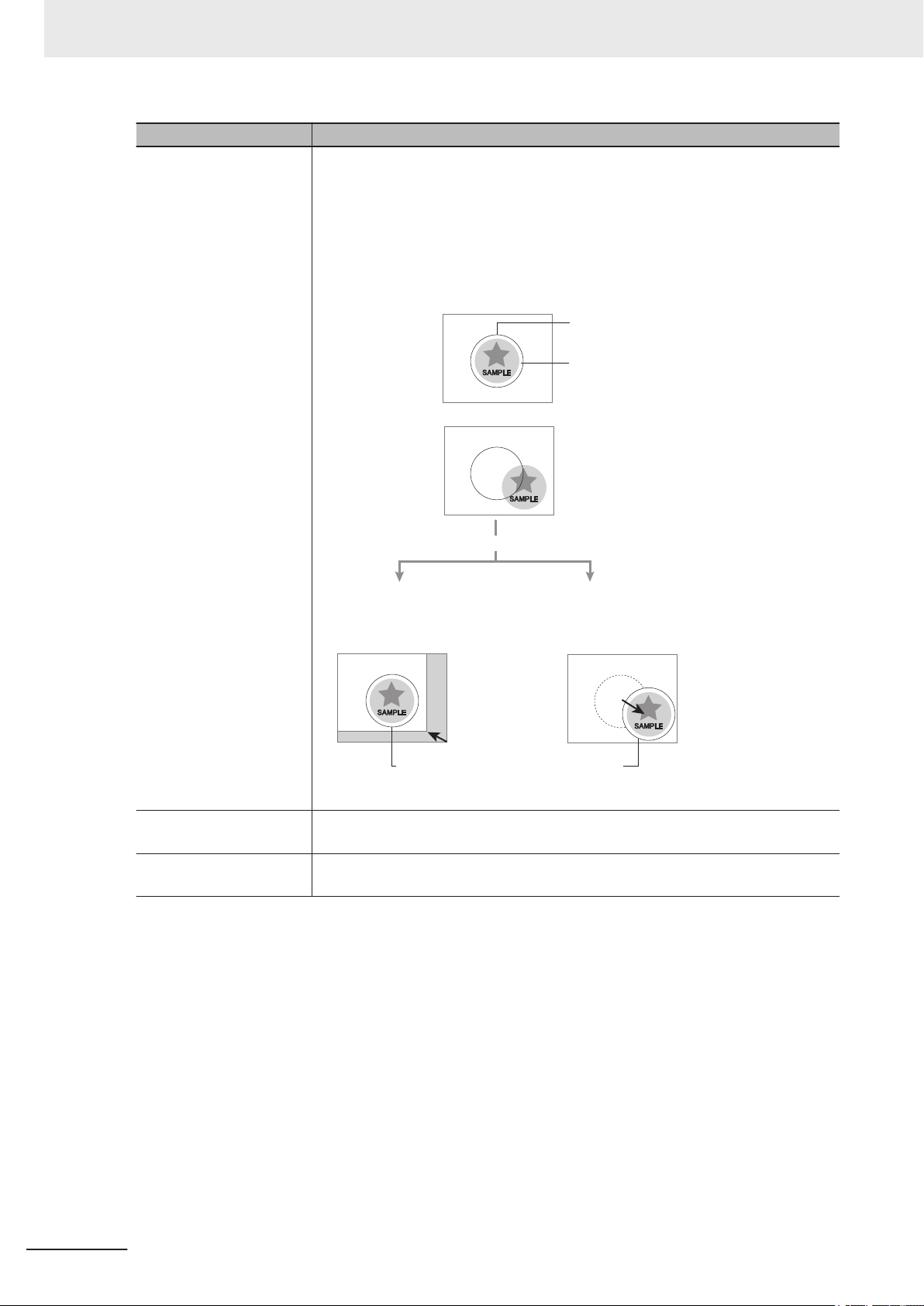
When position of object to be measured is deflected
When position deflection correction is set in advance:
Object to be measured
overflows Measurement area.
Reference position
Measurement area and objects to be measured
are correctly aligned.
Object to be measured
Measurement area
Measurement will be carried out
after measured object enters into Measurement area.
Measurement will be carried out after
moving the Measurement area for a
corresponding deflection.
Measurement will be carried out
after moving the image for a
corresponding deflection and
returning to the reference position.
Terminology
Position compensation When the location and direction of measured objects are not fixed, the positional
Term Definition
deviation between reference position and current position is calculated and measurement is performed after correcting.
Please select processing items that are appropriate to the measurement object
from processing items that are related to position compensation.
Reference position The point that is always the reference. If the location of the registered model is dif-
Model The image pattern that serves as the inspection target. Characteristics portions are
ferent from the reference position, the setting should be changed in Ref. setting.
extracted from images of the object and registered as model registration.
26
FHV Series Smart Camera Setup Manual (Z408-E1)
Page 29
Term Definition
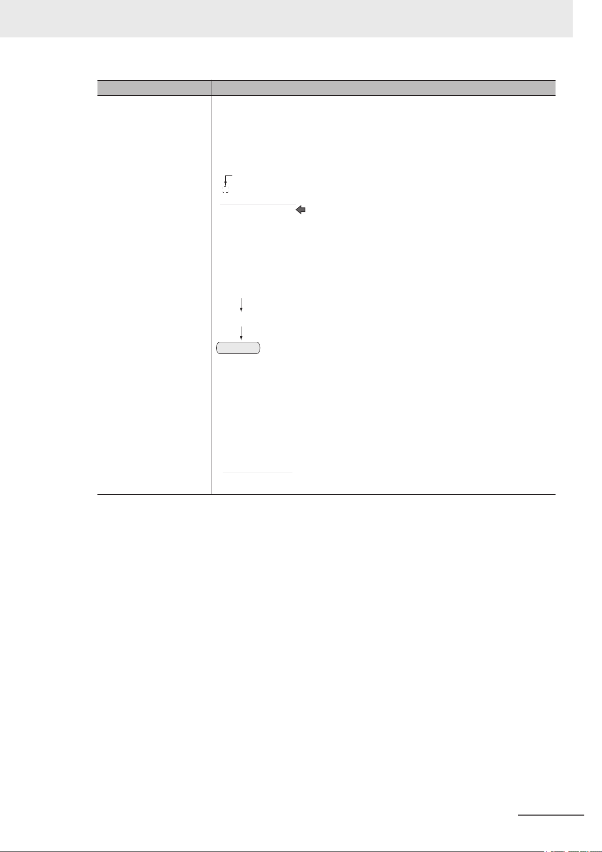
−“1” expresses with 2’s Complement (for 8 bits)
00000000 (= 0)
-)
(In the case of 1, minus 1)
00000001 (= 1)
11111111 (=-1)
00000001 (= 1)
11111110
11111111 (=-1)
Invert all bits
Plus 1
11111111 (= -1)
00001001 (= 9)
+)00001010 (= 10)
2's complement Binary numbers are generally used to represent negative numbers.
Negative numbers are expressed by Inverting all bits of a positive number and
adding 1 to the result.
Ex. -1 is expressed as 2's complement.
-1 can be calculated by 0-1.
There are methods for simple calculation without performing this kind of computation.
For instance, Negative number = inverting all bits of a positive number and then
adding 1 to the result.
Terminology
The first digit is used to judge whether the number is positive or negative.
• When 0: Positive number (or 0)
• When 1: Negative number
The advantage of two's complement numbers is that positive and negative numbers can be used as is in calculations.
Ex. When -1+10=9
FHV Series Smart Camera Setup Manual (Z408-E1)
27
Page 30

Z408-E1-01
Revision code
Cat. No.
Revision History
Revision History
A manual revision code appears as a suffix to the catalog number on the front and back covers of the
manual.
Revision code Date Revised content
A Nov. 2018 Original production
28
FHV Series Smart Camera Setup Manual (Z408-E1)
Page 31

Sections in This Manual
1
2
3
4
5
1
2
3
4
5
I
Confirm the Package
Overview of FHV series
Configuration
Handling and Installation Environment
Installation
I
6
7
Index
6
7
Power Supply and I/O Interface
Software Setup
I
Sections in This Manual
FHV Series Smart Camera Setup Manual (Z408-E1)
29
Page 32

Sections in This Manual
30
FHV Series Smart Camera Setup Manual (Z408-E1)
Page 33

Confirm the Package
1-1 Smart Camera............................................................................................... 1 - 2
1-1-1 FHV7H-□□□□□-C Series ............................................................................... 1 - 2
1-1-2 FHV7H-□□□□□-S□□ Series........................................................................... 1 - 2
1-1-3 FHV7H-□□□□□-S□□-□□ Series ..................................................................... 1 - 3
1-2 Sold Separately ............................................................................................1 - 4
1-2-1 Cables........................................................................................................... 1 - 4
1-2-2 Modules ........................................................................................................ 1 - 5
1-2-3 Accessories .................................................................................................. 1 - 6
1-2-4 Lighting and Lighting Controller .................................................................... 1 - 8
1-2-5 Software........................................................................................................ 1 - 8
1
1
FHV Series Smart Camera Setup Manual (Z408-E1)
1 - 1
Page 34

1 Confirm the Package
1-1
1-1-1
Smart Camera
First, please check to see if the package has all the necessary Smart Camera parts.
FHV7H-□□□□□-C Series
• Smart Camera
FHV7H-□□□□□-C: 1
• Connector cap for Ethernet cable (mounted on the body): 1
• Connector cap for an external lighting (mounted on the body): 1
• C mount cap (mounted on the body): 1
• C mount cover (mounted on the body): 1
• Instruction sheet: 1
• Membership registration: 1
• Compliance sheet: 1
1-1-2
FHV7H-□□□□□-S□□ Series
• Smart Camera
FHV7H-□□□□□-S□□: 1
• Connector cap for Ethernet cable (mounted on the body): 1
• Connector cap for an external lighting (mounted on the body): 1
• Special cover for FHV-LEM-S (mounted on the body): 1
• Instruction sheet: 1 each (Body, and lens module)
• Membership registration: 1
• Compliance sheet: 1
1 - 2
FHV Series Smart Camera Setup Manual (Z408-E1)
Page 35

1 Confirm the Package
1-1-3
FHV7H-□□□□□-S□□-□□ Series
• Smart Camera
FHV7H-□□□□□-S□□-□□: 1
• Connector cap for Ethernet cable (mounted on the body): 1
• Connector cap for an external lighting (mounted on the body): 1
• Instruction sheet: 1 each (Body, lens module, and lighting module)
• Membership registration: 1
• Compliance sheet: 1
1-1 Smart Camera
1
1-1-3 FHV7H-□□□□□-S□□-□□ Series
FHV Series Smart Camera Setup Manual (Z408-E1)
1 - 3
Page 36

1 Confirm the Package
1-2
1-2-1
Sold Separately
Cables
I/O Cables
Appearance Description Model
I/O cable straight
Cable length: 2 m, 3 m, 5 m, 10 m, 20 m
I/O cable right-angle
Cable length: 2 m, 3 m, 5 m, 10 m, 20 m
FHV-VDB □□M
FHV-VDLB □□M
Ethernet Cables
Appearance Description Model
Ethernet cable straight
Cable length: 2 m, 3 m, 5 m, 10 m, 20 m
Ethernet cable right-angle
Cable length: 2 m, 3 m, 5 m, 10 m, 20 m
FHV-VNB □□M
FHV-VNLB □□M
1 - 4
FHV Series Smart Camera Setup Manual (Z408-E1)
Page 37

1 Confirm the Package
1-2-2
Modules
Lens Modules
Appearance Focal distance Model Package contents
6 mm FHV-LEM-S06
9 mm FHV-LEM-S09
12 mm FHV-LEM-S12
16 mm FHV-LEM-S16
25 mm FHV-LEM-S25
• Main unit: 1
• Special cover for FHV-LEM-S: 1
• Screws: M3×8 mm: 5 (including one
spare piece)
• Instruction sheet : 1
• Compliance sheet: 1
If purchasing the Smart Camera with integrated lens module, refer to 1-1-2 FHV7H-□□□□□-S□□ Series
on page 1 - 2 and 1-1-3 FHV7H-□□□□□-S□□-□□ Series on page 1 - 3.
Lighting Modules
Appearance Color
White - LED FHV-LTM-W
Red Typ. 630 nm LED FHV-LTM-R
Infrared light Typ. 850 nm LED FHV-LTM-IR
Multi-color R: Typ. 630 nm
Peak
wavelength
G: Typ. 525 nm
B: Typ. 465 nm
IR:Typ. 850 nm
Source Model Package contents
• Main unit: 1
• Waterproof packing
(small) FHV-XWPCAM:1
• Waterproof packing
(large) FHV-XWPLTM: 1
• Light shielding sheet
FHV-XLS-LTM: 1
LED FHV-LTM-MC
• Lighting cover FHV-
XCV: 1
• Hexagonal wrench
(length: 60 mm): 1
• Instruction sheet: 1
• Compliance sheet: 1
1-2 Sold Separately
1
1-2-2 Modules
If purchasing the Smart Camera with integrated lighting module, refer to the 1-1-3 FHV7H-□□□□□-
S□□-□□ Series on page 1 - 3.
FHV Series Smart Camera Setup Manual (Z408-E1)
1 - 5
Page 38

1 Confirm the Package
1-2-3
Accessories
Optical Filters
Appearance Type Supported wavelength Model
Polarization filter Visible FHV-XPL
Polarization filter Visible to infrared FHV-XPL-IR
Diffusion filter FHV-XDF
Lighting cover FHV-XCV
Waterproof Hoods
Appearance Description Model Package contents
For C mount lens
3Z4S-LE SV-V
series
For C mount lens
3Z4S-LE SV-H
series
FHV-XHD-S
FHV-XHD-L
• Hood cover: 1
• Hood base: 1
• Waterproof packing, FHV-XWP-CAM: 1
• Screws, M3×8 mm: 5
For lens module FHV-XHD-LEM
• Hood cover: 1
• Hood base: 1
• Waterproof packing FHV-XWP-CAM: 2
• Hexagonal wrench: (length: 60 mm): 1
Mounting Fixtures
Appearance Description Model Package contents
For Smart Camera body
and lighting controller
mounting
For lighting controller
mounting
FHV-XMT-7 None
FHV-XMT-7-TCC Screws: M5×8 mm: 5
Waterproof Packings
Appearance Description Model
For camera: 5
*1
FHV-XWP-CAM
1 - 6
For internal lighting: 5
*1
FHV-XWP-LTM
FHV Series Smart Camera Setup Manual (Z408-E1)
Page 39

1 Confirm the Package
Appearance Description Model
For hood: 5
*1. After this was used once, replace this with the new one when mounting and dismounting lens or lighting
module.
*1
FHV-XWP-HD-SL
Waterproof Caps
Appearance Description Model
For lighting connector FHV-XWC-LCN
For Ethernet connector FHV-XWC-ECN
Light-shielding Sheet
Appearance Description Model
For lighting module: 3
*1
FHV-XLS-LTM
1-2 Sold Separately
1
1-2-3 Accessories
*1. After this was used once, replace this with the new one when mounting and dismounting lens or lighting
module.
FHV Series Smart Camera Setup Manual (Z408-E1)
1 - 7
Page 40

1 Confirm the Package
1-2-4
Lighting and Lighting Controller
Appearance Description Model
-
External lighting - FLV series
- FL series
Lighting Controller
(Required to control
external lighting form
a Smart Camera)
For FLV series Camera mount
lighting controller
Analog lighting
controller
For FL series Camera mount
lighting controller
Digital lighting
controller
FLV-TCC series
FLV-ATC series
FL-TCC series
FL-STC series
1-2-5
For the setting method of lighting controllers, refer to those instruction sheets respectively.
Software
Appearance Description Model
- FH_FHV Remote Operation Tool -
The Remote Operation tool and the simulation software are possible to download with free by doing
the member registration after purchasing the Smart Camera. For details, refer to the membership reg-
istration sheet packed with the Smart Camera.
1 - 8
FHV Series Smart Camera Setup Manual (Z408-E1)
Page 41

2
2
Overview of FHV Series
2-1 Overview of System .....................................................................................2 - 2
2-1-1 Basic System of Measurement ..................................................................... 2 - 2
2-2 Flow of Use Procedure ................................................................................2 - 7
FHV Series Smart Camera Setup Manual (Z408-E1)
2 - 1
Page 42

2 Overview of FHV Series
2-1
2-1-1
Overview of System
Basic System of Measurement
FHV series use pre-built packages that contain all the processing tasks (for image input, measurement
processing, displays, outputs, etc.) that are required for vision inspections.
Users arrange these packaged processes to make measurement flows with in order of execution of
the vision inspection.
An FHV executes vision inspections according to user-created flows.
Additional Information
In the FHV settings, a flow containing packaged processes that are arranged in order of execution of processing items and image processing is called a measurement flow.
Processing items and measurement flows can have more than one setting. You can switch the
setting based on the scene to inspect.
For details, refer to the Vision System FH/FHV/FZ5 series User's Manual (Cat. No. Z365).
2 - 2
FHV Series Smart Camera Setup Manual (Z408-E1)
Page 43

Defect
Search
Measurement flow
FHV
Output Unit
Image Sensor
Measurement
trigger
• Judgement
result
• Measured
values
Measurement
results are
output
The measurement flow is executed basically in
order of the unit numbers.
Image input
from the
Camera
Measurement
processing of
the input image
PLC or other external device
Image Input
2 Overview of FHV Series
Concept of Measurement Processing
When the FHV receives a measurement trigger from the PLC or other external device, the image input
from a Camera, measurement processing, and output of measurement results (e.g., OK/NG judge-
ment results) are executed in the order that those processing items are registered in the measurement
flow.
2-1 Overview of System
2
2-1-1 Basic System of Measurement
In the measurement flow, you can change the processing to execute based on the inspection results
or input conditions of the vision inspection.
FHV Series Smart Camera Setup Manual (Z408-E1)
2 - 3
Page 44

FLV series
or
FL series
・PC (Remote Operation Tool)
؞OMRON IPC (NY)
؞Panel computer
؞OMRON PLCقNJ/NX/CJك
؞Other company PLC
I/O Cable
؞FHV-VD(L)B □ M
Switching Hub
Ethernet Cable
・FHV-VN(L)B
Lighting Module
؞White
؞Red
؞IR ray
؞Multi-color
I/O
RS232C
24VDC
Power supply
PLC
Lighting
Controller
Sensor
or
C mount Lens
Lens Module
External
Lighting
Lighting
Controller
Smart Camera
؞
FHV
□
□M□
2 Overview of FHV Series
FHV Series
An example of the system configuration is as follows.
2 - 4
FHV Series Smart Camera Setup Manual (Z408-E1)
Page 45

Smart Camera Models and System Configuration
FHV7H
-□□□□□-□□□-□□
①②③④⑤ ⑥
Model Reference
l
2 Overview of FHV Series
2-1 Overview of System
Model Refer-
ence
① Imaging element type
② Resolution
③ Shutter system
④ Lens type
⑤ Focal length
⑥ Lighting color
Meaning Description
• M: Monochrome
• C: Color
• 004: 0.4 [Mpix]
• 016: 1.6 [Mpix]
• 032: 3.2 [Mpix]
• 050: 5.0 [Mpix]
• 063: 6.3 [Mpix]
• 120: 12.0 [Mpix]
• Non: Global shutter
• R: Rolling shutter
• C: C mount lens
• S: Autofocus lens
• 06: 6 [mm]
• 09: 9 [mm]
• 12: 12 [mm]
• 16: 16 [mm]
• 25: 25 [mm]
• W: White
• R: Red
• IR: Infrared light
• MC: Multi color
2
2-1-1 Basic System of Measurement
FHV Series Smart Camera Setup Manual (Z408-E1)
2 - 5
Page 46

2 Overview of FHV Series
System Configurations
l
For the Smart Camera FHV7 series, there are five configurations below by module combinations.
Smart camera Lens
0.4Mpix
1.6Mpix
3.2Mpix
5.0Mpix
6.3Mpix
12.0Mpix
0.4Mpix
1.6Mpix
3.2Mpix
6.3Mpix
FHV7H□004-□
FHV7H□016-□
FHV7H□032-□
FHV7H□050-□
FHV7H□063R-□
FHV7H□120R-□
FHV7H□004-□
FHV7H□016-□
FHV7H□032-□
FHV7H□063R-□
C mount
lens
3Z4S-LE
SV□□□□□V
3Z4S-LE
SV□□□□□H
FHV lens
module
FHV-LEMS□□
Internal
lighting
N/A IP40 FHV7H-
N/A IP40 FHV7H-
FHV-LTM-□□IP67 FHV7H-
Protective
structure
IP67
FHV-XHDS
FHV-XHDL
IP67
FHV-XHDLEM
Integrated
model
□□□□□-C
N/A C mount
□□□□□S□□
N/A Lens
□□□□□S□□-□□
Appear-
ance
Configura-
tion
C mount
lens/IP40
lens/IP67
Lens
module/IP40
module/IP67
Lens module
/Internal
lighing IP67
2 - 6
FHV Series Smart Camera Setup Manual (Z408-E1)
Page 47

2 Overview of FHV Series
2-2
Flow of Use Procedure
The following table shows the flow for using the FHV.
Procedure Description Reference
Preparations Installation and Wiring Section 4 Handling and Installation
Environment on page 4 - 1
Section 5 Installation on page
5 - 1
↓
Turning ON Power 6-1 When Turning Power ON and
OFF on page 6 - 2
↓
Connecting the Remote Operation
Tool
↓
Language Selection in Dialog Box
(only when the Sensor Controller is
started for the first time)
↓
Main Window (Layout 0) Display Vision System FH/FHV/FZ5 series
↓
Camera Adjustments (Display the
settings dialog box for a Camera
Image Input processing item.)
↓
Select Tool − System settings,
and then under Startup setting,
set the settings for Basic,
Communication, and Operation
mode.
↓
Click Data save, and then select
Function − System restart.
↓
Select Tool - System settings ,
and then set Camera,
Communication and Other.
↓
Click Data save. Vision System FH/FHV/FZ5 series
↓
7-2 Operating the Smart Camera
Remotely [Remote Operation Tool]
on page 7 - 10
Vision System FH/FHV/FZ5 series
User's Manual (Cat. No. Z365)
User's Manual
Vision System FH/FHV/FZ5 series
User's Manual
Vision System FH/FHV/FZ5 series
User's Manual
Vision System FH/FHV/FZ5 series
User's Manual
Vision System FH/FHV/FZ5 series
User's Manual
User's Manual
2-2 Flow of Use Procedure
2
FHV Series Smart Camera Setup Manual (Z408-E1)
2 - 7
Page 48

2 Overview of FHV Series
Procedure Description Reference
Scene Editing In the Main Window (layout 0), edit
↓↑
Testing Execute test measurements.
↓
Measuring
(Operation)
↓
Management and Analysis Save and analyze measurement
Vision System FH/FHV/FZ5 series
the measurement flow.
User's Manual
• Register processing items.
• Set the properties for each proc-
essing item.
↓
Click Data save. Vision System FH/FHV/FZ5 series
User's Manual
Vision System FH/FHV/FZ5 series
(In the Main Window (layout 0),
click Measure.)
↓
Adjust the parameters for each
processing item.
↓
Click Data save. Vision System FH/FHV/FZ5 series
In the Main Window (layout 0), click
Switch layout, and then select
Main Window (Layout 1).
↓
In the Main Window (layout 1),
check the communications with the
PLC.
↓
In the Main Window (layout 1), execute commands from the PLC,
such as measurement trigger commands.
data and images.
User's Manual
Vision System FH/FHV/FZ5 series
User's Manual
User's Manual
Vision System FH/FHV/FZ5 series
User's Manual
Vision System FH/FHV/FZ5 series
User's Manual
Vision System FH/FHV/FZ5 series
User's Manual
Vision System FH/FHV/FZ5 series
User's Manual
2 - 8
FHV Series Smart Camera Setup Manual (Z408-E1)
Page 49

Configuration
3-1 Smart Camera............................................................................................... 3 - 2
3-1-1 FHV Series ................................................................................................... 3 - 2
3-2 Cables ......................................................................................................... 3 - 10
3-2-1 I/O Cables................................................................................................... 3 - 10
3-2-2 Ethernet Cables .......................................................................................... 3 - 13
3-3 Lens Modules .............................................................................................3 - 15
3-3-1 Specifications.............................................................................................. 3 - 15
3-3-2 Meaning of Optical Chart ............................................................................ 3 - 17
3-4 C Mount Lenses.......................................................................................... 3 - 20
3-4-1 Specifications.............................................................................................. 3 - 20
3-4-2 Meaning of Optical Chart ............................................................................ 3 - 30
3-5 Lighting Modules........................................................................................ 3 - 37
3-5-1 Specifications.............................................................................................. 3 - 37
3-5-2 Dimensions ................................................................................................. 3 - 38
3-6 Optical Filters .............................................................................................3 - 39
3-6-1 Specifications.............................................................................................. 3 - 39
3-6-2 Dimensions ................................................................................................. 3 - 39
3-7 Waterproof Hoods...................................................................................... 3 - 41
3-7-1 Specifications.............................................................................................. 3 - 41
3-7-2 Dimensions ................................................................................................. 3 - 42
3-8 Mounting Fixtures ...................................................................................... 3 - 46
3-8-1 Specfications .............................................................................................. 3 - 46
3-8-2 Dimensions ................................................................................................. 3 - 46
3-9 Software ......................................................................................................3 - 48
3-9-1 Remote Operation Tool............................................................................... 3 - 48
3-9-2 Simulation Software.................................................................................... 3 - 48
3
3
FHV Series Smart Camera Setup Manual (Z408-E1)
3 - 1
Page 50

3 Configuration
3-1
3-1-1
Smart Camera
FHV Series
Specifications
Item
Specifications
Operation Mode
Standard Yes
Double
speed
multi-input
Non-stop
adjustment
mode
Parallel
processing
Possible No.
of captured
images
Possible No.
of logging
images to
Smart Camera
Possible No.
of scenes
UI operation Remote Operation Tool
Setup Create the processing flow using Flow editing.
Language Japanese, English, Simplified Chinese, Traditional Chinese, German, French, Italian, Span-
M004 C004 M016 C016 M032 C032 M050 C050 M063R C063R M120R C120R
Yes
Yes
Yes
256 64 36 25 19 10
214 52 25 15 12 5
*1
128
ish, Korean, Vietnamese, Polish
FHV7H-
3 - 2
FHV Series Smart Camera Setup Manual (Z408-E1)
Page 51

3 Configuration
Item
Imaging
CMOS
Image
elements
Color/Monochrome
Effective
pixels (HxV)
Pixel size 6.9×6.9 μm 3.45×3.45
Imaging
area H×V
(opposing
corner)
Shutter
system
Shutter
function
Partial
function
Frame rate
(image
acquisition
time)
Lens
mounting
Field of
view,
Installation
distance
M004 C004 M016 C016 M032 C032 M050 C050 M063R C063R M120R C120R
1/2.9-inch
equivalent
Monochro
me
720 × 540 1440 × 1080 2048 × 1536 2448 × 2048 3072 × 2048 4000 × 3000
5.0×3.8
(6.3 mm)
Global Shutter Rolling shutter (Global reset
Electronic shutter: Shutter speed can be set from 1 μs to
100 ms.
4 to 540
lines
(4-line increments)
430 fps
(2.3 ms)
C mount
Selecting a lens according to the field of view and installation distance
Color Mon-
1/2.9-inch
equivalent
ochro
me
μm
5.0×3.8
(6.3 mm)
4 to 1080
lines
(4-line increments)
224 fps
(4.5 ms)
1/1.8-inch
equivalent
Color Mon-
ochro
me
3.45×3.45
μm
7.1×5.3
(8.9 mm)
4 to 1536
lines
(4-line increments)
55 fps
(18.0 ms)
FHV7H-
2/3-inch
equivalent
Color Mon-
ochro
me
3.45×3.45
μm
8.5×7.1
(11.1 mm)
4 to 2048
lines
(4-line increments)
35 fps
(28.0 ms)
1/1.8-inch
equivalent
Color Mon-
ochro
me
2.4×2.4 μm 1.85×1.85 μm
7.4×5.0
(8.9 mm)
mode compatible)
Electronic
shutter: Shutter speed can
be set from 55
μs to 100 ms.
4 to 2048
lines
(4-line increments)
59 fps
(16.7 ms)
1/1.7-inch
equivalent
Color Mon-
ochro
me
7.4×5.6
(9.3 mm)
Electronic
shutter: Shutter speed can
be set from 84
μs to 100 ms.
4 to 3000
lines
(4-line increments)
19 fps
(25.0 ms)
Color
3-1 Smart Camera
3
3-1-1 FHV Series
FHV Series Smart Camera Setup Manual (Z408-E1)
3 - 3
Page 52

3 Configuration
Item
External Interface
Serial RS-232C×1
Ethernet Protocol: Non-procedure (TCP/UDP)
EtherNet/IP Yes (Target/Ethernet port)
PROFINET Yes (Slave/Ethernet port), Conformance class A
EtherCAT N/A
Parallel I/O NPN/PNP common
Parallel I/F High-speed input: 1, General input: 3, High-speed output: 1, General output: 4
Encoder I/F N/A
Monitor I/F N/A
USB I/F N/A
SD Card I/F microSD card: SDHC×1
Indicator
Lamps
Supply Voltage 21.6 VDC to 26.4 VDC (When an I/O cable with 20 m is connected, it is 24.0 VDC to 26.4
Current
Consumption
Built-in FAN N/A
Usage Environment
Main PWR: Green, RUN: Green, LINK: Yellow, BUSY: Green, OR: Yellow, ERR: Red
SD SD ACCESS: Yellow
Ambient
temperature
range
Ambient
humidity
range
Ambient
atmosphere
Vibration
tolerance
Shock
resistance
Noise
immunity
Grounding Class D grounding (100Ω or less grounding resistance) * Existing the third class grounding
M004 C004 M016 C016 M032 C032 M050 C050 M063R C063R M120R C120R
I/F: 1000BASE-T×1
VDC.)
With lighting modules: 4.2 A
Without lighting modules: 0.60 A
Operating: 0 to +40℃, Storage: -25 to +65℃ (with no icing or condensation)
Operating & Storage: 35 to 85%RH (With no condensation)
No corrosive gases
Oscillation frequency: 10 to 150Hz, Half amplitude: 0.35 mm, Vibration direction: X/Y/Z,
Sweep time: 8 minute/count, Sweep count: 10
With lens modules: Half amplitude: 0.15 mm (Others are the same as above.)
Impact force: 150 m/s2, Test direction: 6 directions, three time each (up/down, front/behind,
left/right)
Fast transient burst
・ DC power
Direct infusion: 2kV, Pulse rising: 5 ns, Pulse width: 50 ns, Burst continuation time: 15 ms/
0.75 ms, Period: 300 ms, Application time: 1 min.
・ I/O line
Direct infusion: 1kV, Pulse rising: 5 ns, Pulse width: 50 ns, Burst continuation time: 15 ms/
0.75 ms, Period: 300 ms, Application time: 1 min.
FHV7H-
3 - 4
FHV Series Smart Camera Setup Manual (Z408-E1)
Page 53

3 Configuration
Item
External shape
Dimensions 110 mm × 68.5 mm × 55.5 mm (HxWxD)
Weight Approx. 670 g
Degree of
protection
Case
material
Accessories
M004 C004 M016 C016 M032 C032 M050 C050 M063R C063R M120R C120R
With lighting modules or waterproof hoods: IEC60529 - IP67
(except a connector cap removed)
Other than the above: IEC60529 - IP40
Aluminum die-casting (ADC12)
• Connector cap for Ethernet cable (mounted on the body): 1
FHV7H-
• Connector cap for an external lighting (mounted on the body): 1
• C mount cap (mounted on the body): 1
• C mount cover (mounted on the body): 1
• Instruction sheet: 1
• Membership registration: 1
• Compliance sheet: 1
*1. The number of scenes can be increased up to 1,024 with the Conversion scene group data tool.
3-1 Smart Camera
3
3-1-1 FHV Series
FHV Series Smart Camera Setup Manual (Z408-E1)
3 - 5
Page 54

1
10
6
5
9
4 3 2
8
7
10
3 Configuration
Component Names and Functions
No. Name Description
1 Imaging unit Captures images.
2 Connector for I/O cable Use this connector when connecting the smart camera with a
3 Connector for Ethernet cable Use this connector when connecting the smart camera with a
4 Connector for external lighting Use this connector when connecting an external lighting and the
5 Connector to attach microSD card Use this connector to attach a microSD card. Do not extract/
6 Operation
7 SD ACCESS (Yel-
8 Connector for lighting module
9 Connector for lens module (Black) Use this connector when mounting the lens module.
10 Mounting screw holes Use them to screw up the smart camera.
indicator
(white)
power supply or an external device using an I/O cable.
Dedicated I/O cable: FHV-VD
personal computer and so on using an Ethernet cable. Dedicated Ethernet cable: FHV-VN
external lighting controller.
Connectable external lighting controller: FL-TCC and FLVTCC
insert the microSD card during processing.
Otherwise, measurement time may be influenced or data may
be broken.
PWR (Green) Lights while power is supplied.
RUN (Green) Lights when switching to the layout in which the RUN signal out-
put is set ON.
LINK (Yellow) Lights when connected with Ethernet equipment and blinks dur-
ing communication.
BUSY (Green) Lights while processing is in progress.
OR (Yellow) Lights when the overall judgment output signal is ON.
ERR (Red) Lights when an error occurs.
Lights when accessing to the microSD card.
low)
Use this connector when mounting the lighting module.
Recommended tightening torque : 2.3N・m
3 - 6
FHV Series Smart Camera Setup Manual (Z408-E1)
Page 55

Dimensions
30.0
36.0
4-M5.0
68.4
126.7
68.5 2.7
36.8 35.0
55.5
65.3
35.5
50.0
98.0
9.2
4-M5.0
110.0
6.0
16.7
12.2
20.5
22.5
69.0
35.5
35.0
35.5
36.0
30.0
5.5dia.
50.0
98.0
5.5dia.
Mounting screw holes (The tolerance: ± 0.1 mm)
OPTICAL AXIS
depth4
depth6
Recommenden tightening torque: 2.3N・m
• FHV7H-□□□□□-C
3 Configuration
3-1 Smart Camera
3
3-1-1 FHV Series
(Unit: mm)
FHV Series Smart Camera Setup Manual (Z408-E1)
3 - 7
Page 56

30.0
36.0
4-M5.0
68.4
126.7
68.5 2.7
36.8 35.0
55.5
82.5
50.0
35.5
50.0
98.0
9.2
4-M5.0
110.0
6.0
16.7
12.2
20.5
22.5
69.0
35.5
35.0
35.5
36.0
30.0
50.0
98.0
OPTICAL AXIS
depth4
depth6
Mounting screw holes (The tolerance: ± 0.1 mm)
Recommenden tightening torque: 2.3N・m
5.5dia.
5.5dia.
3 Configuration
• FHV7H-□□□□□-S□□
(Unit: mm)
3 - 8
FHV Series Smart Camera Setup Manual (Z408-E1)
Page 57

• FHV7H-□□□□□-S□□-□□
30.0
36.0
4-M5.0
91.0
77.0
36.8
55.5
103.2
35.5
50.0
98.0
9.2
4-M5.0
110.0
6.0
16.7
68.52.7
12.2
20.5
22.5
69.0
35.5
35.0
35.5
36.0
30.0
50.0
98.0
OPTICAL AXIS
depth4
depth6
Mounting screw holes (The tolerance: ± 0.1 mm)
Recommenden tightening torque: 2.3N・m
5.5dia.
5.5dia.
3 Configuration
3-1 Smart Camera
3
3-1-1 FHV Series
Additional Information
We have the 2D CAD data or 3D CAD data.
You can download CAD data from www.fa.omron.co.jp.
(Unit: mm)
FHV Series Smart Camera Setup Manual (Z408-E1)
3 - 9
Page 58

3 Configuration
3-2
3-2-1
Cables
I/O Cables
Specifications
• I/O cables (Straight)
Item FHV-VDB 2M FHV-VDB 3M FHV-VDB 5M
Cable length 2 m 3 m 5 m 10 m 20 m
Cable type Bending resistance cable
Connector type Straight connector
Size Power line AWG21
Others AWG26
Outer diameter 9.0±0.3 mm dia.
Min. bending radius Fixed use: 54 mm, Sliding use: 72 mm
Usage
environment
Material Mold part: Nylon, Thermoplastic polyurethane, Sheath part: PVC
Weight Approx. 270 g Approx. 390 g Approx. 620 g Approx. 1200gApprox. 2350
Ambient
temperature
range
Ambient
humidity
range
Ambient
atmosphere
Vibration
tolerance
Shock resistance
Operating: -30 to +80℃, Storage: -30 to +100℃ (with no icing or condensation)
Operating & Storage: 0 to 93%RH (With no condensation)
No corrosive gases
Oscillation frequency: 10 to 150Hz, Half amplitude: 0.35 mm, Vibration direction: X/Y/Z, Sweep time: 8 minute/count, Sweep count: 10
Impact force: 150 m/s2, Test direction: 6 directions, three time each (up/down,
front/behind, left/right)
FHV-VDB
10M
FHV-VDB
20M
g
3 - 10
• I/O cables (Right angle)
Item
Cable length 2 m 3 m 5 m 10 m 20 m
Cable type Bending resistance cable
Connector type Right angle connector
Size Power line AWG21
Others AWG26
Outer diameter 9.0±0.3 mm dia.
Min. bending radius Fixed use: 54 mm, Sliding use: 72 mm
FHV-VDLB2MFHV-VDLB3MFHV-VDLB5MFHV-VDLB
10M
FHV Series Smart Camera Setup Manual (Z408-E1)
FHV-VDLB
20M
Page 59

3 Configuration
Item
Usage
environment
Material Mold part: Nylon, Thermoplastic polyurethane, Sheath part: PVC
Weight Approx. 270 g Approx. 390 g Approx. 620 g Approx. 1200gApprox. 2350
Ambient
temperature
range
Ambient
humidity
range
Ambient
atmosphere
Vibration
tolerance
Shock resistance
FHV-VDLB
2M
Operating: -30 to +80℃, Storage: -30 to +100℃ (with no icing or condensation)
Operating & Storage: 0 to 93%RH (With no condensation)
No corrosive gases
Oscillation frequency: 10 to 150Hz, Half amplitude: 0.35 mm, Vibration direction: X/Y/Z, Sweep time: 8 minute/count, Sweep count: 10
Impact force: 150 m/s2, Test direction: 6 directions, three time each (up/down,
front/behind, left/right)
FHV-VDLB
3M
FHV-VDLB5MFHV-VDLB
10M
FHV-VDLB
20M
g
3-2 Cables
3
3-2-1 I/O Cables
FHV Series Smart Camera Setup Manual (Z408-E1)
3 - 11
Page 60

M12x1.0
16.20 dia.
57.50
50
9 dia.
5
15 dia.
55
L
48.45
23.50
M12x1
9 dia.
50
5
15 dia.
40.20
55
L
3 Configuration
Dimensions
• I/O cable (Straight)
• I/O cable (Right angle)
(Unit: mm)
3 - 12
Additional Information
We have the 2D CAD data or 3D CAD data.
You can download CAD data from www.fa.omron.co.jp.
FHV Series Smart Camera Setup Manual (Z408-E1)
(Unit: mm)
Page 61

3 Configuration
3-2-2
Ethernet Cables
Specifications
• Ethernet Cables (Straight)
Item FHV-VNB 2M FHV-VNB 3M FHV-VNB 5M
Cable length 2 m 3 m 5 m 10 m 20 m
Cable type Bending resistance cable
Connector type Straight connector
Outer diameter 7.2+0.3 mm dia.
Min. bending radius Fixed use: 35 mm, Sliding use: 70 mm
Usage
environment
Material Mold part: Nylon, Thermoplastic polyurethane, Sheath part: Polyurethane
Weight Approx. 210 g Approx. 240 g Approx. 310 g Approx. 380 g Approx. 730 g
Ambient
temperature
range
Ambient
humidity
range
Ambient
atmosphere
Vibration
tolerance
Shock
resistance
Operating: -40 to +80℃, Storage: -40 to +100℃ (with no icing or condensation)
Operating & Storage: 0 to 93%RH (With no condensation)
No corrosive gases
Oscillation frequency: 10 to 150Hz, Half amplitude: 0.35 mm, Vibration direction: X/Y/Z, Sweep time: 8 minute/count, Sweep count: 10
Impact force: 150 m/s2, Test direction: 6 directions, three time each (up/down,
front/behind, left/right)
FHV-VNB
10M
FHV-VNB
20M
3-2 Cables
3
3-2-2 Ethernet Cables
• Ethernet cables (Right angle)
Item
Cable length 2 m 3 m 5 m 10 m 20 m
Cable type Bending resistance cable
Connector type Right angle connector
Outer diameter 7.2+0.3 mm dia.
Min. bending radius Fixed use: 35 mm, Sliding use: 70 mm
Usage
environment
Material Mold part: Nylon, Thermoplastic polyurethane, Sheath part: Polyurethane
Ambient
temperature
range
Ambient
humidity
range
Ambient
atmosphere
Vibration
tolerance
Shock
resistance
FHV-VNLB
2M
Operating: -40 to +80℃, Storage: -40 to +100℃ (with no icing or condensation)
Operating & Storage: 0 to 93%RH (With no condensation)
No corrosive gases
Oscillation frequency: 10 to 150Hz, Half amplitude: 0.35 mm, Vibration direction: X/Y/Z, Sweep time: 8 minute/count, Sweep count: 10
Impact force: 150 m/s2, Test direction: 6 directions, three time each (up/down,
front/behind, left/right)
FHV-VNLB
3M
FHV-VNLB5MFHV-VNLB
10M
FHV-VNLB
20M
FHV Series Smart Camera Setup Manual (Z408-E1)
3 - 13
Page 62

58
M12 x 1
21
7.20 dia.
L
53.50
16.20 dia.
15 dia.
48.45
45.90
M12 x 1
7.20 dia.
53.50
L
23.50
15 dia.
3 Configuration
Item
FHV-VNLB2MFHV-VNLB3MFHV-VNLB5MFHV-VNLB
10M
FHV-VNLB
20M
Weight Approx. 210 g Approx. 240 g Approx. 310 g Approx. 380 g Approx. 730 g
Dimensions
• Ethernet cable (Straight)
(Unit: mm)
• Ethernet cable (Right angle)
3 - 14
Additional Information
We have the 2D CAD data or 3D CAD data.
You can download CAD data from www.fa.omron.co.jp.
FHV Series Smart Camera Setup Manual (Z408-E1)
(Unit: mm)
Page 63

3 Configuration
3-3
3-3-1
Lens Modules
Specifications
Item
Focal length 6 mm 9 mm 12 mm 16 mm 25 mm
Installation distance 59 to 1000
Usage environment
Ambient temperature range
Ambient humidity
range
Ambient
atmosphere
Vibration tolerance
Shock resistance
External shape
Dimension 50 mm × 41 mm × 31 mm (HxWxD)
Weight Approx. 50 g
Case material Polycarbonate
S06 S09 S12 S16 S25
60 to 1000
mm
Operating: 0 to +40℃, Storage: -25 to +65℃ (with no icing or condensation)
Operating & Storage: 35 to 85%RH (With no condensation)
No corrosive gases
Oscillation frequency: 10 to 150Hz, Half amplitude: 0.15 mm*1, Vibration direction:
X/Y/Z, Sweep time: 8 minute/count, Sweep count: 10
Impact force: 150 m/s2, Test direction: 6 directions, three time each (up/down,
front/behind, left/right)
mm
FHV-LEM-
60 to 1000
mm
110 to 2000mm188 to 2000
mm
3-3 Lens Modules
3
3-3-1 Specifications
Accessories
*1. When the lens module is mounted to the product, the specificatins of vibration tolerance are changed.
• Special cover for FHV-LEM-S: 1
• Screws: M3×8 mm: 5 (including one spare piece)
• Instruction sheet : 1
• Compliance sheet: 1
FHV Series Smart Camera Setup Manual (Z408-E1)
3 - 15
Page 64

54dia.
16.316.3
2525
17 12.5
25 16
19 19
3.5
31
13.8
9.81
3 Configuration
Dimensions
Additional Information
We have the 2D CAD data or 3D CAD data.
You can download CAD data from www.fa.omron.co.jp.
(Unit: mm)
3 - 16
FHV Series Smart Camera Setup Manual (Z408-E1)
Page 65

FHV7H-□□□□□-S□□ FHV7H-□□□□□-S□□-□□
Mounting surface
of front side
Camera distance
(mm)
Y field of view (mm)
Mounting surface
of front side
Camera distance
(mm)
Y field of view (mm)
3 Configuration
3-3-2
Meaning of Optical Chart
How to View the Optical Chart
The X axis of the optical chart shows the field of vision (mm).
The Y axis of the optical chart shows the camera installation distance (mm).
3-3 Lens Modules
3
3-3-2 Meaning of Optical Chart
The lengths of the fields of view given in the optical charts are the lengths of the Y axis.
Precautions for Correct Use
The optical axis may vary product by product. When mounting this module, be sure to confirm
the center position of the video on the monitor. The optical axis of this product may vary over a
couple of pixels due to the variation of ambient temperature because of the material characteristics.
Precautions for Correct Use
Select the model by confirming the field of view and camera installation distance on the optical
diagram. In addition, the field of view may vary product by product.
When mounting this product, be sure to confirm video using the monitor.
FHV Series Smart Camera Setup Manual (Z408-E1)
3 - 17
Page 66

1,000
100
10
10 100 1,000
FHV-LEM-S25
FHV-LEM-S16
FHV-LEM-S12
FHV-LEM-S09
FHV-LEM-S06
Camera placement distance (mm)
Y field of view (mm)
1,000
100
10
Camera placement distance (mm)
Y field of view (mm)
10 100 1,000
FHV-LEM-S25
FHV-LEM-S16
FHV-LEM-S12
FHV-LEM-S09
FHV-LEM-S06
3 Configuration
Optical Chart
• FHV7H-□004, FHV7H-□016
• FHV7H-□032
3 - 18
FHV Series Smart Camera Setup Manual (Z408-E1)
Page 67

• FHV7H-□063R
1,000
100
10
10 100 1,000
FHV-LEM-S25
FHV-LEM-S16
FHV-LEM-S12
FHV-LEM-S09
FHV-LEM-S06
Camera placement distance (mm)
Y field of view (mm)
3 Configuration
3-3 Lens Modules
3
3-3-2 Meaning of Optical Chart
FHV Series Smart Camera Setup Manual (Z408-E1)
3 - 19
Page 68

30.4
29.5 dia.
29.5
29.5 dia.
30.0
29 dia.
34.0
28 dia.
29.5
29 dia.
24.0
29 dia.
24.5
29 dia.
33.5 [WD: ∞] to
37.5 [WD: 300]
29 dia.
37.0 [WD: ∞] to
39.4 [WD: 1000]
32 dia.
42.0 [WD: ∞] to
44.4 [WD: 1000]
32 dia.
32 dia.
43.9 [WD: ∞] to
46.3 [WD: 1000]
3 Configuration
3-4
3-4-1
C Mount Lenses
Specifications
SV-V Series
FHV7H-□004 and FHV7H-□016 are recommended.
Model
Appearance/
Dimensions [mm]
Focal length [mm] 3.5 4.5 6 8
Aperture(F No.) 1.4 to Close 1.4 to Close 1.4 to Close 1.3 to Close
Filter size - - M27.0 P0.5 M25.5 P0.5
Max. sensor size 1/3-inch 1/3-inch 1/3-inch 1/3-inch
Mount C mount
SV-03514V SV-04514V SV-0614V SV-0813V
3Z4S-LE
Model
Appearance/
Dimensions [mm]
Focal length [mm] 12 16 25 35
Aperture(F No.) 1.4 to Close 1.4 to Close 1.4 to Close 1.8 to Close
Filter size M27.0 P0.5 M27.0 P0.5 M27.0 P0.5 M27.0 P0.5
Max. sensor size 1/3-inch 1/3-inch 1/3-inch 1/3-inch
Mount C mount
Model
Appearance/
Dimensions [mm]
SV-1214V SV-1614V SV-2514V SV-3518V
3Z4S-LE
SV-5018V SV-7527V SV-10035V
3Z4S-LE
3 - 20
Focal length [mm] 50 75 100
Aperture(F No.) 1.8 to Close 2.7 to Close 3.5 to Close
Filter size M30.5 P0.5 M30.5 P0.5 M30.5 P0.5
Max. sensor size 1/3-inch 1/3-inch 1/3-inch
Mount C mount
FHV Series Smart Camera Setup Manual (Z408-E1)
Page 69

SV-H Series
57.5
42 dia.
52.5
39 dia.
51.0
30 dia.
47.5
30 dia.
36.0
30 dia.
45.5
44 dia.
57.5
44 dia.
49.5 [WD:∞] to
54.6 [WD:1200]
36 dia.
66.5 [WD:∞] to
71.6 [WD:2000]
39 dia.
FHV7H-□032, FHV7H-□050, FHV7H-□063R, and FHV7H-□120R are recommended.
3 Configuration
Model
Appearance/
Dimensions [mm]
Focal length [mm] 6 8 12 16
Aperture(F No.) 1.4 to 16 1.4 to 16 1.4 to 16 1.4 to 16
Filter size M40.5 P0.5 M35.5 P0.5 M27.0 P0.5 M27.0 P0.5
Max. sensor size 2/3-inch 2/3-inch 2/3-inch 2/3-inch
Mount C mount
Model
Appearance/
Dimensions [mm]
Focal length [mm] 25 35 50 75
Aperture(F No.) 1.4 to 16 1.4 to 16 1.4 to 16 2.5 to Close
Filter size M27.0 P0.5 M35.5 P0.5 M40.5 P0.5 M34.0 P0.5
Max. sensor size 2/3-inch 2/3-inch 2/3-inch 1-inch
Mount C mount
SV-0614H SV-0814H SV-1214H SV-1614H
SV-2514H SV-3514H SV-5014H SV-7525H
3Z4S-LE
3Z4S-LE
3-4 C Mount Lenses
3
3-4-1 Specifications
Model
Appearance/
Dimensions [mm]
Focal length [mm] 100
Aperture(F No.) 2.8 to Close
Filter size M37.5 P0.5
Max. sensor size 1-inch
Mount C mount
3Z4S-LE
SV-10028H
FHV Series Smart Camera Setup Manual (Z408-E1)
3 - 21
Page 70

29.0 [0.01x] 〜 29.2 [0.04x]
31 dia.
23.1 [0.01x] 〜 23.4 [0.06x]
31 dia.
3 Configuration
Vibration / Shock-resistance Lens VS-MCA Series for C Mount
Camera
FHV7H-□004, FHV7H-□016, FHV7H-□032, FHV7H-□050, FHV7H-□063R, and FHV7H-□120R are rec-
ommended.
Model
Appearance/
Dimensions [mm]
Focal length [mm] 4 mm
Filter size M27.0 P0.5
Optical
magnification
Aperture
(fixed F No.)
Depth of field
*2
[mm]
Maximum sensor
size
Mount C mount
Model
Appearance/
Dimensions [mm]
0.01x 0.02x 0.04x
2 5.6 8 2 5.6 8 2 5.6 8
1680.0 4560.0 6480.0 420.0 1140.0 1640.0 105.0 290.0 415.0
1/2-inch
3Z4S-LE VS-MCA4-□□□□
3Z4S-LE VS-MCA6.5-□□□□
*1
*1
Focal length [mm] 6.5 mm
Filter size M27.0 P0.5
Optical
magnification
Aperture
(fixed F No.)
Depth of field
*2
[mm]
Maximum sensor
size
Mount C mount
0.01x 0.03x 0.06x
2 5.6 8 2 5.6 8 2 5.6 8
1840.0 4560.0 6480.0 204.4 515.6 728.9 51.1 131.1 188.9
1/2-inch
3 - 22
FHV Series Smart Camera Setup Manual (Z408-E1)
Page 71

24.2 [0.02x] 〜 25.5 [0.15x]
31 dia.
27.9 [0.03x] 〜 32.0 [0.30x]
31 dia.
3 Configuration
Model
Appearance/
Dimensions [mm]
Focal length [mm] 10 mm
Filter size M27.0 P0.5
Optical
0.02x 0.10x 0.15x
magnification
Aperture
2 5.6 8 2 5.6 8 2 5.6 8
(fixed F No.)
Depth of field
*2
[mm]
Maximum sensor
460.0 1140.0 1640.0 19.2 49.6 70.4 9.2 22.8 32.7
1/2-inch
size
Mount C mount
Model
Appearance/
Dimensions [mm]
3Z4S-LE VS-MCA10-□□□□
3Z4S-LE VS-MCA15-□□□□
*1
3-4 C Mount Lenses
3
3-4-1 Specifications
*1
Focal length [mm] 15 mm
Filter size M27.0 P0.5
Optical
0.03x 0.20x 0.30x
magnification
Aperture
2 5.6 8 2 5.6 8 2 5.6 8
(fixed F No.)
Depth of field
*2
[mm]
Maximum sensor
186.7 515.6 728.9 4.8 13.4 19.2 2.3 6.5 9.2
2/3-inch
size
Mount C mount
FHV Series Smart Camera Setup Manual (Z408-E1)
3 - 23
Page 72

24.5 [0.04x] 〜 32.0 [0.40x]
31 dia.
27.0 [0.05x] 〜 38.5 [0.50x]
31 dia.
3 Configuration
Model
Appearance/
Dimensions [mm]
Focal length [mm] 20 mm
Filter size M27.0 P0.5
Optical
0.04x 0.25x 0.40x
magnification
Aperture
2 5.6 8 2 5.6 8 2 5.6 8
(fixed F No.)
Depth of field
*2
[mm]
Maximum sensor
105.0 290.0 415.0 3.2 9.0 12.8 1.5 3.9 5.6
2/3-inch
size
Mount C mount
Model
Appearance/
Dimensions [mm]
3Z4S-LE VS-MCA20-□□□□
3Z4S-LE VS-MCA25-□□□□
*1
*1
Focal length [mm] 25 mm
Filter size M27.0 P0.5
Optical
0.05x 0.25x 0.50x
magnification
Aperture
2 5.6 8 2 5.6 8 2 5.6 8
(fixed F No.)
Depth of field
*2
[mm]
Maximum sensor
67.2 188.8 268.8 3.2 9.0 12.8 1.0 2.7 3.8
2/3-inch
size
Mount C mount
3 - 24
FHV Series Smart Camera Setup Manual (Z408-E1)
Page 73

24.5 [0.06x] 〜 36.2 [0.45x]
31 dia.
32.0 [0.26x] 〜 45.7 [0.65x]
31 dia.
3 Configuration
Model
Appearance/
Dimensions [mm]
Focal length [mm] 30 mm
Filter size M27.0 P0.5
Optical
0.06x 0.15x 0.45x
magnification
Aperture
2 5.6 8 2 5.6 8 2 5.6 8
(fixed F No.)
Depth of field
*2
[mm]
Maximum sensor
53.3 131.1 188.9 8.2 22.8 32.7 1.3 3.2 4.6
2/3-inch
size
Mount C mount
Model
Appearance/
Dimensions [mm]
3Z4S-LE VS-MCA30-□□□□
3Z4S-LE VS-MCA35-□□□□
*1
3-4 C Mount Lenses
3
3-4-1 Specifications
*1
Focal length [mm] 35 mm
Filter size M27.0 P0.5
Optical
0.26x 0.30x 0.65x
magnification
Aperture
2 5.6 8 2 5.6 8 2 5.6 8
(fixed F No.)
Depth of field
*2
[mm]
Maximum sensor
3.0 8.4 12.0 2.2 6.5 9.2 0.7 1.7 2.5
2/3-inch
size
Mount C mount
FHV Series Smart Camera Setup Manual (Z408-E1)
3 - 25
Page 74

44.0 [0.08x] 〜 63.4 [0.48x]
31 dia.
70.0 [0.14x] 〜 105.5 [0.62x]
31 dia.
3 Configuration
Model
Appearance/
Dimensions [mm]
Focal length [mm] 50 mm
Filter size M27.0 P0.5
Optical
0.08x 0.20x 0.48x
magnification
Aperture
2 5.6 8 2 5.6 8 2 5.6 8
(fixed F No.)
Depth of field
*2
[mm]
Maximum sensor
32.5 75.0 107.5 6.0 13.4 19.2 1.3 2.9 4.1
2/3-inch
size
Mount C mount
Model
Appearance/
Dimensions [mm]
3Z4S-LE VS-MCA50-□□□□
3Z4S-LE VS-MCA75-□□□□
*1
*1
Focal length [mm] 75 mm
Filter size M27.0 P0.5
Optical magnifica-
0.14x 0.20x 0.62x
tion
Aperture (fixed F
2 5.6 8 2 5.6 8 2 5.6 8
No.)
Depth of field
*2
[mm]
Maximum sensor
16.7 28.6 41.2 9.2 13.4 19.2 1.3 2.5 3.6
2/3-inch
size
Mount C mount
*1. Insert the aperture into □□□□ in the model number as follows.
F=2: Blank
F=5: F5.6
F=8: F8
*2. When an allowable diameter of confusion circle is 0.04 mm
3 - 26
FHV Series Smart Camera Setup Manual (Z408-E1)
Page 75

3 Configuration
High-resolution Telecentric Lens VS-TCH Series for C Mount Lens
for 2/3-inch Image Sensor
FHV7H-□004, FHV7H-□01, FHV7H-□032, FHV7H-□050, FHV□□-□063R, and FHV□□-□120R are rec-
ommended.
Model
Optical magnification (±5%) 0.5× 1.0×
Field of
view
(±5%)
(VxH)
[mm]
WD [mm]
Effective F No. 9.42 9.49 9.94 10.49
Depth of field [mm]
Resolution [μm]
TV distortion 0.02% 0.02% 0.01% 0.02%
Max. sensor size 2/3-inch
FHV7H-□004/□016
FHV7H-□032 1/1.8-inch
FHV7H-□063R 1/1.8-inch
FHV7H-□120R 1/1.7-inch
FHV7H-□50 2/3-inch
*2
*3
*4
1/2.9-inch
equivalent
equivalent
equivalent
equivalent
equivalent
3Z4S-LE VS-TCH05 3Z4S-LE VS-TCH1
-65□□□□ -110□□□□ -65□□□□ -110□□□□
9.9×7.5 5.0×3.7
14.1×10.6 7.1×5.3
14.8×9.8 7.4×4.9
14.8×11.1 7.4×5.6
16.9×14.1 8.5×7.1
75.3 110.8 68.8 110.3
3 3.04 0.8 0.84
12.43 12.9 6.71 6.99
3-4 C Mount Lenses
3
3-4-1 Specifications
Model
Optical magnification (±5%) 1.5× 2.0×
Field of
view
(±5%)
(VxH)
[mm]
WD [mm]
Effective F No. 11.8 11.97 13.6 13.5
Depth of field [mm]
Resolution [μm]
TV distortion 0.01% 0.02% 0.03% 0.03%
Max. sensor size 2/3-inch
FHV7H-□004/□016
FHV7H-□032 1/1.8-inch
FHV7H-□063R 1/1.8-inch
FHV7H-□120R 1/1.7-inch
FHV7H-□50 2/3-inch
*2
*3
*4
1/2.9-inch
equivalent
equivalent
equivalent
equivalent
equivalent
3Z4S-LE VS-TCH1.5 3Z4S-LE VS-TCH2
-65□□□□ -110□□□□ -65□□□□ -110□□□□
3.3×2.5 2.5×1.9
4.7×3.5 3.5×2.7
4.9×3.3 3.7×2.5
4.9×3.7 3.7×2.8
5.6×4.7 4.2×3.5
65 110.8 65 110.8
0.4 0.43 0.3 0.27
5.24 5.33 4.53 4.53
FHV Series Smart Camera Setup Manual (Z408-E1)
3 - 27
Page 76

3 Configuration
Model
Optical magnification (±5%) 4.0×
Field of
view
(±5%)
(VxH)
[mm]
WD [mm]
Effective F No. 17.91 22.2
Depth of field [mm]
Resolution [μm]
TV distortion 0.02% 0.03%
Max. sensor size 2/3-inch
*1. Insert the shape into in the model number as follows.
Straight: -O
Coaxial: CO-O
*2. The working distance is from the end of the lens to the sensor.
*3. The depth of field is calculated using a allowable diameter of confusion circle of 0.04 mm.
*4. The resolution is calculated using a wavelength of 550 nm.
FHV7H-□004/□016
FHV7H-□032 1/1.8-inch equivalent 1.8×1.3
FHV7H-□063R 1/1.8-inch equivalent 1.8×1.2
FHV7H-□120R 1/1.7-inch equivalent 1.9×1.4
FHV7H-□50 2/3-inch equivalent 2.1×1.8
*2
*3
*4
1/2.9-inch equivalent 1.4×0.9
3Z4S-LE VS-TCH4
-65□□□□ -110□□□□
65 110.8
0.09 0.11
3 3.73
Note:
(1) Fixing the lens or other reinforcement may be required depending on the installation angle or op-
erating environment (vibration/shock).
When fixing the lens, insulate the lens from the fixture.
(2) The above specifications are values calculated from the optical design and can vary depending on
installation conditions.
3 - 28
FHV Series Smart Camera Setup Manual (Z408-E1)
Page 77

3 Configuration
Non-telecentric Macro Lens VS-MC Series for C Mount Camera
Model
Optical magnification (±5%) 0.1x 0.3x 0.5x 1.0x
Field of view
(±5%)
(VxH)
[mm]
WD [mm]
Effective F No. 4.43 5.29 6.10 8.14
Resolution [μm]
Depth of field [mm]
TV distortion 0.01% or less 0.00% or less 0.00% or less 0.00% or less
*1. The working distance is from the end of the lens to the sensor.
*2. The resolution is calculated using a wavelength of 550 nm.
*3. The depth of field is calculated using an allowable diameter of confusion circle of 0.04 mm.
FHV7H□004/-□016
FHV7H-□032 1/1.8-inch
FHV7H□063R
FHV7H□120R
FHV7H-□050 2/3-inch
*1
*2
*3
1/2.9-inch
equivalent
equivalent
1/1.8-inch
equivalent
1/1.7-inch
equivalent
equivalent
-MC01-330 -MC03-180 -MC05-130 -MC1-80
49.7x37.3 16.6x12.4 9.9x7.5 5.0x3.7
70.7x53.0 23.6x17.7 14.1x10.6 7.1x5.3
73.7x49.2 24.6x16.4 14.8x9.8 7.4x4.9
74.0x55.5 24.7x18.5 14.8x11.1 7.4x5.6
84.5x70.7 28.2x23.6 16.9x14.1 8.5x7.1
325.5 184.8 126.3 82.4
30.5 11.6 8.2 5.5
35.4 4.7 2.0 0.7
3Z4S-LE VS
3-4 C Mount Lenses
3
3-4-1 Specifications
FHV Series Smart Camera Setup Manual (Z408-E1)
3 - 29
Page 78

FHV7H--C
Mounting surface
of front side
Camera distance
(mm)
WD (mm)
Y field of view (mm)
3 Configuration
3-4-2
Meaning of Optical Chart
How to View the Optical Chart
The X axis of the optical chart shows the field of view [mm].
The Y axis of the optical chart shows the camera installation distance [mm] or WD.
The lengths of the fields of view given in the optical charts are the lengths of the Y axis.
Precautions for Correct Use
The optical axis may vary product by product. When mounting this module, be sure to confirm
the center position of the video on the monitor. The optical axis of this product may vary over a
couple of pixels due to the variation of ambient temperature because of the material characteristics.
Precautions for Correct Use
Select the model by confirming the field of view and camera installation distance on the optical
diagram. In addition, the field of view may vary product by product.
When mounting this product, be sure to confirm video using the monitor.
3 - 30
FHV Series Smart Camera Setup Manual (Z408-E1)
Page 79

Optical Chart
W
W
W
W
W
W
W
W
W
W
W
W
W
W
W
W
W
W
W
W
W
W
W
W
W
W
W
W
W
W
W
W
W
W
W
W
W
W
W
W
W
W
W
W
W
W
W
W
W
W
W
W
W
W
W
W
W
W
W
W
W
W
W
W
W
W
W
W
W
W
W
W
W
W
W
1,000
100
10
Camera placement distance (mm)
Y field of view (mm)
1 10 100 1,000
SV-10035V
SV-7527V
SV-5018V
SV-3518V
SV-2514V
5,000
3Z4S-LE
SV-1614V
SV-1214V
SV-0813V
SV-0614V
SV-04514V
SV-03514V
W
W
W
W
W
W
W
W
W
W
W
W
W
W
W
W
W
W
W
W
W
W
W
W
W
W
W
W
W
W
W
W
W
W
W
W
W
W
W
W
W
W
W
W
W
W
W
W
W
W
W
W
W
W
W
W
W
W
W
W
1,000
100
10
Camera placement distance (mm)
Y field of view (mm)
1 10 100 1,000
SV-10028H
SV-7525H
SV-5014H
SV-3514H
SV-2514H
5,000
3Z4S-LE
SV-1614H
SV-1214H
SV-0814H
SV-0614H
Normal Lenses
l
(a) Smart camera: FHV7H-□004, FHV7H-□016 (for 3Z4S-LE SV-V series)
3 Configuration
3-4 C Mount Lenses
3
3-4-2 Meaning of Optical Chart
(b) Smart camera: FHV7H-□004, FHV7H-□016 (for 3Z4S-LE SV-H series)
FHV Series Smart Camera Setup Manual (Z408-E1)
3 - 31
Page 80

W
W
W
W
W
W
W
W
W
W
W
W
W
W
W
W
W
W
W
W
W
W
W
W
W
W
W
W
W
W
W
W
W
W
W
W
W
W
W
W
W
W
W
W
W
W
W
W
W
W
W
W
W
W
W
W
W
W
W
W
1,000
100
10
1 10 100 1,000
SV-10028H
SV-7525H
SV-5014H
SV-3514H
SV-2514H
5,000
3Z4S-LE
SV-1614H
SV-1214H
SV-0814H
SV-0614H
Camera placement distance (mm)
Y field of view (mm)
1,000
100
10
Camera placement distance (mm)
Y field of view (mm)
1 10 100 1,000
SV-10028H
SV-7525H
SV-5014H
SV-3514H
SV-2514H
5,000
3Z4S-LE
SV-1614H
SV-1214H
SV-0814H
SV-0614H
W
W
W
W
W
W
W
W
W
W
W
W
W
W
W
W
W
W
W
W
W
W
W
W
W
W
W
W
W
W
W
W
W
W
W
W
W
W
W
W
W
W
W
W
W
W
W
W
W
W
W
W
W
W
W
W
W
W
W
W
3 Configuration
(c) Smart camera: FHV7H-□032 (for 3Z4S-LE SV-H series)
(d) Smart camera: FHV7H-□050 (for 3Z4S-LE SV-H series)
3 - 32
FHV Series Smart Camera Setup Manual (Z408-E1)
Page 81

(e) Smart camera: FHV7H-□063R (for 3Z4S-LE SV-H series)
W
W
W
W
W
W
W
W
W
W
W
W
W
W
W
W
W
W
W
W
W
W
W
W
W
W
W
W
W
W
W
W
W
W
W
W
W
W
W
W
W
W
W
W
W
W
W
W
W
W
W
W
W
W
W
W
W
W
W
W
1,000
100
10
1 10 100 1,000
SV-10028H
SV-7525H
SV-5014H
SV-3514H
SV-2514H
5,000
3Z4S-LE
SV-1614H
SV-1214H
SV-0814H
SV-0614H
Camera placement distance (mm)
Y field of view (mm)
W
W
W
W
W
W
W
W
W
W
W
W
W
W
W
W
W
W
W
W
W
W
W
W
W
W
W
W
W
W
W
W
W
W
W
W
W
W
W
W
W
W
W
W
W
W
W
W
W
W
W
W
W
W
W
W
W
W
W
W
1,000
100
10
1 10 100 1,000
SV-10028H
SV-7525H
SV-5014H
SV-3514H
SV-2514H
5,000
3Z4S-LE
SV-1614H
SV-1214H
SV-0814H
SV-0614H
Camera placement distance (mm)
Y field of view (mm)
3 Configuration
3-4 C Mount Lenses
3
3-4-2 Meaning of Optical Chart
(f) Smart camera: FHV7H-□120R (for 3Z4S-LE SV-H series)
FHV Series Smart Camera Setup Manual (Z408-E1)
3 - 33
Page 82

1,000
100
10
1 10 100 1,000
W
W
W
W
W
W
W
W
W
W
W
W
W
W
W
W
W
W
W
W
W
W
W
W
W
W
W
W
W
W
W
W
W
W
VS-MCA75
VS-MCA50
VS-MCA35
VS-MCA30
VS-MCA25
VS-MCA20
VS-MCA15
VS-MCA10
VS-MCA6.5
VS-MCA4
Camera placement distance (mm)
Y field of view (mm)
W
W
W
W
W
W
W
W
W
W
W
W
W
W
W
W
W
W
W
W
W
W
W
W
W
W
W
W
W
W
1,000
100
10
1 10 100 1,000
VS-MCA75
VS-MCA50
VS-MCA35
VS-MCA30
VS-MCA25
VS-MCA20
VS-MCA15
Camera placement distance (mm)
Y field of view (mm)
3 Configuration
Vibration / Shock-resistance Lens
l
(a) Smart Camera: FHV7H-□004, FHV7H-□016 (for 3Z4S-LE VS-MCA series)
(b) Smart camera: FHV7H-□032 (for 3Z4S-LE VS-MCA series)
3 - 34
FHV Series Smart Camera Setup Manual (Z408-E1)
Page 83

(c) Smart camera: FHV7H-□050 (for 3Z4S-LE VS-MCA series)
1,000
100
10
1 10 100 1,000
VS-MCA75
VS-MCA50
VS-MCA35
VS-MCA30
VS-MCA25
VS-MCA20
VS-MCA15
W
W
W
W
W
W
W
W
W
W
W
W
W
W
W
W
W
W
W
W
W
W
W
W
W
W
W
W
W
W
Camera placement distance (mm)
Y field of view (mm)
W
W
W
W
W
W
W
W
W
W
W
W
W
W
W
W
W
W
W
W
W
W
W
W
W
W
W
W
W
W
1,000
100
10
1 10 100 1,000
VS-MCA75
VS-MCA50
VS-MCA35
VS-MCA30
VS-MCA25
VS-MCA20
VS-MCA15
Camera placement distance (mm)
Y field of view (mm)
3 Configuration
3-4 C Mount Lenses
3
3-4-2 Meaning of Optical Chart
(d) Smart camera: FHV7H-□063R (for 3Z4S-LE VS-MCA series)
FHV Series Smart Camera Setup Manual (Z408-E1)
3 - 35
Page 84

W
W
W
W
W
W
W
W
W
W
W
W
W
W
W
W
W
W
W
W
W
W
W
W
W
W
W
W
W
W
1,000
100
10
1 10 100 1,000
VS-MCA75
VS-MCA50
VS-MCA35
VS-MCA30
VS-MCA25
VS-MCA20
VS-MCA15
Camera placement distance (mm)
Y field of view (mm)
3 Configuration
(e) Smart camera: FHV7H-□120R (for 3Z4S-LE VS-MCA series)
3 - 36
FHV Series Smart Camera Setup Manual (Z408-E1)
Page 85

3 Configuration
3-5
3-5-1
Lighting Modules
Specifications
Model FHV-LTM-W FHV-LTM-R FHV-LTM-IR FHV-LTM-MC
Color White Red Infrared light Multi color
Peak wave length - Typ. 630 nm Typ. 850 nm R: Typ. 630 nm
G: Typ. 525 nm
B: Typ. 465 nm
IR: Typ. 850 nm
Light source LED LED LED LED
Risk group Group 2 Group 1 Group 1 R: Group 1
G: Group 2
B: Group 2
Usage environment
Ambient
temperature
range
Ambient humidity
range
Ambient
atmosphere
Vibration tolerance Oscillation frequency: 10 to 150Hz, Half amplitude: 0.35 mm, Vibration direction:
Shock resistance
Dimensions 52 mm × 91 mm × 77 mm (HxWxD)
Weight 270 g 270 g 270 g 270 g
Material Aluminum die-casting (ADC12), polycarbonate
Accessories
Operating: 0 to +40℃, Storage: -25 to +65℃ (with no icing or condensation)
Operating & Storage: 35 to 85%RH (With no condensation)
No corrosive gases
X/Y/Z, Sweep time: 8 minute/count, Sweep count: 10
Impact force: 150 m/s2, Test direction: 6 directions, three time each (up/down, front/
behind, left/right)
• Waterproof packing (small) FHV-XWP-CAM:1
• Waterproof packing (large) FHV-XWP-LTM: 1
• Light shielding sheet FHV-XLS-LTM: 1
• Lighting cover FHV-XCV: 1
• Hexagonal wrench (length: 60 mm): 1
• Instruction sheet: 1
• Compliance sheet: 1
IR: Group 1
3-5 Lighting Modules
3
3-5-1 Specifications
FHV Series Smart Camera Setup Manual (Z408-E1)
3 - 37
Page 86

91
77
51
1.1
3 Configuration
3-5-2
Dimensions
(Unit: mm)
Additional Information
We have the 2D CAD data or 3D CAD data.
You can download CAD data from www.fa.omron.co.jp.
3 - 38
FHV Series Smart Camera Setup Manual (Z408-E1)
Page 87

77
63
91
77
1.1 10.7
3 Configuration
3-6
3-6-1
Optical Filters
Specifications
Model FHV-XDF FHV-XPL FHV-XPL-IR FHV-XCV
Filter type Diffusion filter Polarization filter Polarization filter Lighting cover for
replacement
Wavelength Visible to infrared Visible Visible to infrared Visible to infrared
Adapted lighting module FHV-LTM-W
FHV-LTM-R
FHV-LTM-IR
FHV-LTM-MC
Usage environment
Ambient
temperature
range
Ambient humidity
range
Vibration tolerance No corrosive gases
Shock resistance Oscillation frequency: 10 to 150Hz, Half amplitude: 0.35 mm, Vibration direction:
Vibration tolerance
Material Aluminum (A6061), polycarbonate
Weight Approx. 70 g Approx. 70 g Approx. 70 g Approx. 70 g
Operating: 0 to +40℃, Storage: -25 to +65℃ (with no icing or condensation)
Operating & Storage: 35 to 85%RH (With no condensation)
X/Y/Z, Sweep time: 8 minute/count, Sweep count: 10
Impact force: 150 m/s2, Test direction: 6 directions, three time each (up/down, front/
behind, left/right)
FHV-LTM-W
FHV-LTM-R
FHV-LTM-MC (Infrared light is not
used.)
FHV-LTM-W
FHV-LTM-R
FHV-LTM-IR
FHV-LTM-MC
FHV-LTM-W
FHV-LTM-R
FHV-LTM-IR
FHV-LTM-MC
3-6 Optical Filters
3
3-6-1 Specifications
3-6-2
Dimensions
(Unit: mm)
FHV Series Smart Camera Setup Manual (Z408-E1)
3 - 39
Page 88

3 Configuration
Additional Information
We have the 2D CAD data or 3D CAD data.
You can download CAD data from www.fa.omron.co.jp.
3 - 40
FHV Series Smart Camera Setup Manual (Z408-E1)
Page 89

3 Configuration
3-7
3-7-1
Waterproof Hoods
Specifications
Model FHV-XHD-S FHV-XHD-L FHV-XHD-LEM
Suitable lens 3Z4S-LE SV-V series
SV-0614V
SV-0813V
SV-1214V
SV-1614V
SV-2514V
Usage
environment
Material Aluminum (A6061), polycarbonate
Weight Approx. 220 g Approx. 220 g Approx. 220 g
*1. This is not available in FHV7H-□050、FHV7H-□063R、FHV7H-□120R.
*2. This is not available in FHV7H-□050.
Ambient temperature
range
Ambient humidity
range
Ambient atmosphere No corrosive gases
Vibration tolerance Oscillation frequency: 10 to 150Hz, Half amplitude: 0.35 mm, Vibration
Shock resistance
Operating: 0 to +40℃, Storage: -25 to +65℃ (with no icing or condensation)
Operating & Storage: 35 to 85%RH (With no condensation)
direction: X/Y/Z, Sweep time: 8 minute/count, Sweep count: 10
Impact force: 150 m/s2, Test direction: 6 directions, three time each (up/
down, front/behind, left/right)
3Z4S-LE SV-H series
SV-0614H
SV-0814H
SV-1214H
SV-1614H
SV-2514H
SV-3514H
SV-5014H
*1
*2
FHV-LEM-S series
FHV-LEM-S06
FHV-LEM-S09
FHV-LEM-S12
FHV-LEM-S16
FHV-LEM-S25
3-7 Waterproof Hoods
3
3-7-1 Specifications
FHV Series Smart Camera Setup Manual (Z408-E1)
3 - 41
Page 90

60
60
46
42
M52x0.75DEPTH2.5
56
60
( 62.4)
60
60
46
42
M52x0.75DEPTH2.5
79
60
( 85.4 )
3 Configuration
3-7-2
Dimensions
• FHV-XHD-S
• FHV-XHD-L
(Unit: mm)
3 - 42
(Unit: mm)
FHV Series Smart Camera Setup Manual (Z408-E1)
Page 91

• FHV-XHD-LEM
61
61
68.4
68.4
M62x0.75DEPTH3
(21)
( 36.21)
30.0
36.0
4-M5.0
68.4
126.7
68.5 2.7
36.8 35.0
55.5
114.7
60.0
35.5
50.0
98.0
9.2
4-M5.0
110.0
6.0
16.7
12.2
20.5
22.5
69.0
35.5
35.0
35.5
36.0
30.0
50.0
98.0
OPTICAL AXIS
Mounting screw holes (The tolerance: ± 0.1 mm)
depth4
depth6
Recommenden tightening torque: 2.3N・m
5.5dia.
5.5dia.
3 Configuration
3-7 Waterproof Hoods
3
3-7-2 Dimensions
• Outer size when the waterproof hood, FHV-XHD-S, is mounted.
(Unit: mm)
FHV Series Smart Camera Setup Manual (Z408-E1)
(Unit: mm)
3 - 43
Page 92

30.0
36.0
4-M5.0
68.4
126.7
68.5 2.7
36.8 35.0
55.5
137.7
60.0
35.5
50.0
98.0
9.2
4-M5.0
110.0
6.0
16.7
12.2
20.5
22.5
69.0
35.5
35.0
35.5
36.0
30.0
50.0
98.0
OPTICAL AXIS
Mounting screw holes (The tolerance: ± 0.1 mm)
depth4
depth6
Recommenden tightening torque: 2.3N・m
5.5dia.
5.5dia.
30.0
36.0
4-M5.0
68.4
68.4
36.8
55.5
88.5
35.5
50.0
98.0
9.2
4-M5.0
110.0
6.0
16.7
68.52.7
12.2
20.5
22.5
69.0
35.5
35.0
35.5
36.0
30.0
50.0
98.0
OPTICAL AXIS
Mounting screw holes (The tolerance: ± 0.1 mm)
depth4
depth6
Recommenden tightening torque: 2.3N・m
5.5dia.
5.5dia.
3 Configuration
• Outer size when the waterproof hood, FHV-XHD-L, is mounted.
• Outer size when the waterproof hood, FHV-XHD-LED, is mounted.
(Unit: mm)
3 - 44
(Unit: mm)
FHV Series Smart Camera Setup Manual (Z408-E1)
Page 93

Additional Information
We have the 2D CAD data or 3D CAD data.
You can download CAD data from www.fa.omron.co.jp.
3 Configuration
3-7 Waterproof Hoods
3
3-7-2 Dimensions
FHV Series Smart Camera Setup Manual (Z408-E1)
3 - 45
Page 94

110
36 ±0.05
70
50 ±0.05
70
94
30 ±0.05
84
95
98 ±0.05
4-
8-5.2dia.
0
+0.1
6-R6
2-
12
12-M2
6-M4
4-R6
1/4-20UNC
4-M5
56.8 22
89.6
12
28
25
77.2
10
4
5.2dia.
0
+0.1
3 Configuration
3-8
3-8-1
Mounting Fixtures
Specfications
Model FHV-XMT-7 FHV-XMT-7-TCC
Purpose Specifal fixture for FHV7 series
For Smart Camera body and
lighting controller mounting
Usage
environment
Ambient temperature range Operating: 0 to +40℃, Storage: -25 to +65℃ (with no icing or
condensation)
Ambient humidity range Operating & Storage: 35 to 85%RH (With no condensation)
Vibration tolerance No corrosive gases
Shock resistance Oscillation frequency: 10 to 150Hz, Half amplitude: 0.35 mm,
Vibration direction: X/Y/Z, Sweep time: 8 minute/count, Sweep
count: 10
Vibration tolerance
Impact force: 150 m/s2, Test direction: 6 directions, three time
each (up/down, front/behind, left/right)
Material Aluminum (A6061) POM (Black)
Weight Approx. 220 g Approx. 50 g
For lighting controller mounting
3-8-2
Dimensions
• FHV-XMT-7
3 - 46
(Unit: mm)
FHV Series Smart Camera Setup Manual (Z408-E1)
Page 95

• FHV-XMT-7-TCC
36 ±0.05
68
106
15
40
51
30 ±0.05
2-R5
50
12-M2
6-
5.5dia.
Penetration
6-
10.5dia.
Countersinking90deg
89.6
20
12
28
22
53
5
3 Configuration
3-8 Mounting Fixtures
3
(Unit: mm)
3-8-2 Dimensions
Additional Information
We have the 2D CAD data or 3D CAD data.
You can download CAD data from www.fa.omron.co.jp.
FHV Series Smart Camera Setup Manual (Z408-E1)
3 - 47
Page 96

3 Configuration
3-9
3-9-1
3-9-2
Software
There are two special software:
• FH_FHV Remote Operation tool
• Simulation software
Remote Operation Tool
This Remote Operation tool supports Smart Camera of all FHV series. It is used to set conditions for
inspection and measurement, and output image processing results according to the set conditions.
You can download the simulation software with free by registering as our member after purchasing.
For details, please check the membership registration card packed in the package.
Simulation Software
The simulation software allows you to experience the operability of FHV series on PC.
You can download the simulation software with free by registering as our member after purchasing.
For details, please check the membership registration card packed in the package.
3 - 48
FHV Series Smart Camera Setup Manual (Z408-E1)
Page 97

4
Handling and Installation Environment
4-1 Warning......................................................................................................... 4 - 2
4
FHV Series Smart Camera Setup Manual (Z408-E1)
4 - 1
Page 98

4 Handling and Installation Environment
4-1
Warning
WARNING
This product must be used according to this manual and the instruction sheet.
Failure to observe this may result in the impairment of functions and performance of the
product.
Please do not use this product to directly or indirectly use to detect the human body for the
purpose of ensuring the safety.
Precautions for Safe Use
Installation Environment
• Do not use the product in areas where flammable or explosive gases are present.
• Do not install the product close to high-voltage devices and power devices in order to secure
the safety of operation and maintenance.
• Do not install the product to a place where vibrations and/or impacts are expected.
• Do not install the product near to a device causing noises. if the product is installed in a noisy
environment and operational errors are caused, be sure to take shielding measures.
Precautions for Correct Use
Installation Location
In order to prevent the product from becoming inoperable or malfunction, and to prevent other
adverse effects to the performance or equipment, please observe the following.
• A location where the ambient temperature does not exceed the rated range (operating: 0 to
40°C, storage: -25 to 65°C).
• A location where the temperature does not vary sharply (condensation occurs).
• A location where relative temperature does not exceed a range of 35-85%RH.
• A location not exposed to corrosive gases or combustible gases.
• A location not exposed to dust, salt, or metal powder.
• A location not exposed to direct vibration or impact.
• A location not exposed to strong disturbance light (laser light, arc welding light, or ultraviolet
light).
• A location not near a heating appliance or exposed to direct sunlight.
• A location not exposed to mist of water, oil, or chemicals or misty atmosphere.
• A location not exposed to strong magnetic/electric fields.
• A location not near a high-voltage device or power device.
• A location where rubber quality is not deteriorated.
MicroSD Card Handling
• If removing the microSD card, confirm that data are not being read or written before removing
it.
• Do not insert the microSD card inversely, obliquely, or as twisting it.
• While data are being read in or written to the microSD card, the SD ACCESS LED on the
smart camera main unit is turned on for a while. Remove the card after checking that the LED
is completely turned off.
• Except when inserting or removing the microSD card, put the cover of the microSD card inserting connector and screw it up before using the product.
Camera Installation
• In an environment exposed to high humidity and sharp temperature fluctuation, the inside of
the lighting cover may become cloudy in rare cases. If it becomes cloudy, remove the lighting
cover and wipe off the inside with a soft cloth.
• If installing smart camera main units side by side, secure a space of 30 mm or more wide
between them.
4 - 2
FHV Series Smart Camera Setup Manual (Z408-E1)
Page 99

Installation
5
5-1 Assembling Equipment ...............................................................................5 - 2
5-1-1 C Mount Lens / IP40 Configuration............................................................... 5 - 2
5-1-2 C Mount Lens / IP67 Configuration............................................................... 5 - 3
5-1-3 Lens Module / IP40 Configuration ................................................................ 5 - 5
5-1-4 Lens Module / IP67 Configuration ................................................................ 5 - 8
5-1-5 Lens Module / Internal Lighting / IP67 Configuration.................................. 5 - 10
5-2 Installing the Smart Camera...................................................................... 5 - 14
5-2-1 How to Connect .......................................................................................... 5 - 14
5-2-2 When Connecting the Smart Camera to a Lighting Controller.................... 5 - 18
5
FHV Series Smart Camera Setup Manual (Z408-E1)
5 - 1
Page 100

Lens mounting position
FHV7H-□□□□-C
5 Installation
5-1
5-1-1
Assembling Equipment
C Mount Lens / IP40 Configuration
1 Attach the C Mount Lens to the Smart Camera body.
5 - 2
2 Securely tighten the C mount lens.
3 Adjust focus and aperture and fix the them.
FHV Series Smart Camera Setup Manual (Z408-E1)
 Loading...