

Omron FHV Series, FHV7-S Series, FH-5 Series, FHV7-C Series, FH-1 Series Operation Manual
...Page 1
Vision Sensor
FH/FHV Series
Vision System
Operation Manual for Sysmac Studio
FH-1£££/FH-1£££-££
FH-2£££/FH-2£££-££
FH-3£££/FH-3£££-££
FH-5£££/FH-5£££-££
FHV7£-£££££-C
FHV7£-£££££-S££/FHV7£-£££££-S££-££
FHV7£-£££££-H££/FHV7£-£££££-H££-££
Z343-E1-10
Page 2

NOTE
• All rights reserved.
• No part of this publication may be reproduced, stored in a retrieval system, or transmitted, in any
form, or by any means, mechanical, electronic, photocopying, recording, or otherwise, without the
prior written permission of OMRON.
• No patent liability is assumed with respect to the use of the information contained herein. Moreover
because OMRON is constantly striving to improve its high-quality products, the information con-
tained in this manual is subject to change without notice. Every precaution has been taken in the
preparation of this manual. Nevertheless, OMRON assumes no responsibility for errors or omis-
sions.
Neither is any liability assumed for damages resulting from the use of the information contained in
this publication.
Trademarks
• Sysmac and SYSMAC are trademarks or registered trademarks of OMRON Corporation in Japan
and other countries for OMRON factory automation products.
• This software is based in part on the work of the Independent JPEG Group.
• Microsoft, Windows, Windows Vista, Excel, and Visual Basic are either registered trademarks or
trademarks of Microsoft Corporation in the United States and other countries.
• Intel, Core and Pentium are trademarks of Intel Corporation in the U.S. and/or other countries.
• EtherCAT® is registered trademark and patented technology, licensed by Beckhoff Automation
GmbH, Germany.
• ODVA, CIP, CompoNet, DeviceNet, and EtherNet/IP are trademarks of ODVA.
• The SD, SDHC, microSD, and microSDHC logos are trademarks of SD-3C, LLC.
,
• QR Code is a registered trademark of DENSO W
AVE INCORPORATED.
• MELSEC is a registered trademarks of Mitsubishi Electric Corporation.
Other company names and product names in this document are the trademarks or registered trade-
marks of their respective companies.
Copyrights
Microsoft product screen shots reprinted with permission from Microsoft Corporation.
Page 3

Introduction
Thank you for purchasing the FH/FHV Series.
This manual contains information that is necessary to use the FH/FHV Series.
Please read this manual and make sure you understand the functionality and performance of the
FH/FHV Series before you attempt to use it in a control system.
Keep this manual in a safe place where it will be available for reference during operation.
Intended Audience
This manual is intended for the following personnel, who must also have knowledge of electrical sys-
tems (an electrical engineer or the equivalent).
• Personnel in charge of introducing FA systems.
• Personnel in charge of designing FA systems.
• Personnel in charge of installing and maintaining FA systems.
• Personnel in charge of managing FA systems and facilities.
Introduction
Applicable Products
This manual covers the following products.
• FH-1£££
• FH-1£££-££
• FH-2£££
• FH-2£££-££
• FH-3£££
• FH-3£££-££
• FH-5£££
• FH-5£££-££
• FH-L£££
• FH-L£££-££
• FHV7£-£££££-C
• FHV7£-£££££-S££/FHV7£-£££££-S££-££
• FHV7£-£££££-H££/FHV7£-£££££-H££-££
Part of the specifications and restrictions are given in other manuals. Refer to Relevant Manuals on
Relevant Manuals on page 2 and Related Manuals on page 18.
FH/FHV Series Vision System Operation Manual for Sysmac Studio (Z343-E1)
1
Page 4
Relevant Manuals
Relevant Manuals
The following table provides the relevant manuals for the FH/FHV Series.
Read all of the manuals that are relevant to your system configuration and application before you use
the FH/FHV Series.
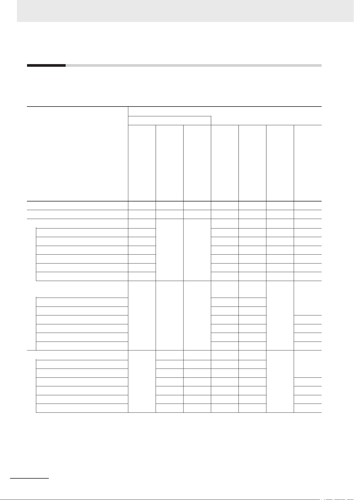
User's Manual
Purpose of use
Basic information
FH/FHV Series Vision System
FH Series Vision System
Hardware Setup Manual
Manual
FHV Series Smart Camera
Setup Manual
FH/FHV Series Vision System
Processing Item Function
Reference Manual
Programming Manual
FH/FZ5 Series Vision System
Macro Customize Functions
FH/FHV Series Vision System
User’s Manual
for Communications Settings
FH/FHV Series Vision System
Operation Manual
for Sysmac Studio
Overview of FH series
Overview of FHV7 series
Setup and Wiring
EtherCAT
EtherNet/IP
PROFINET
Ethernet
RS-232C
Parallel interface
Setup the communication setting of Sensor Controller
EtherCAT
EtherNet/IP
PROFINET
Ethernet
RS-232C
Parallel interface
Setup the Sensor Controller
EtherCAT
EtherNet/IP
PROFINET
Ethernet
RS-232C
Parallel interface
l l
l l
l l
l
l l l l
l
l l
2
FH/FHV Series Vision System Operation Manual for Sysmac Studio (Z343-E1)
Page 5

Purpose of use
Basic information
FH/FHV Series Vision System
User's Manual
Hardware Setup Manual
FH Series Vision System
FHV Series Smart Camera
Setup Manual
Relevant Manuals
Manual
FH/FHV Series Vision System
Processing Item Function
Reference Manual
FH/FZ5 Series Vision System
Macro Customize Functions
Programming Manual
FH/FHV Series Vision System
User’s Manual
for Communications Settings
FH/FHV Series Vision System
Operation Manual
for Sysmac Studio
Create and Set the Scene
EtherCAT
EtherNet/IP
PROFINET
Ethernet
RS-232C
Parallel interface
Optimizing the Scene Flow
EtherCAT
EtherNet/IP
PROFINET
Ethernet
RS-232C
Parallel interface
Connecting the Controller
EtherCAT
EtherNet/IP
PROFINET
Ethernet
RS-232C
Parallel interface
Using Helpful Functions
EtherCAT
EtherNet/IP
PROFINET
Ethernet
RS-232C
Parallel interface
Troubleshooting and Problem Solving
l
l l
l l
l
l l l l
l
l
l
FH/FHV Series Vision System Operation Manual for Sysmac Studio (Z343-E1)
3
Page 6
4-9
4 Installation and Wiring
NJ-series CPU Unit Hardware User’s Manual (W500)
stinU gnitnuoM 3-4
4
stnenopmoC rellortnoC gnitcennoC 1-3-4
4-3 Mounting Units
The Units that make up an NJ-series Controller can be connected simpl y b y p res sin g t he Un it s to ge th e r
and locking the sliders by moving them toward the back of the Units . The End Co v er is connect ed in the
same way to the Unit on the far right side of the Controller.
1 Join the Units so that the connectors fit exactly.
2 The yellow sliders at the top and bottom of each Unit lock the Units together. Move the sliders
toward the back of the Units as shown below until they click into place.
Precautions for Correct UsePrecautions for Correct Use
4-3-1 Connecting Controller Components
Connector
Hook
Hook holes
Slider
Lock
Release
Move the sliders toward the back
until they lock into place.
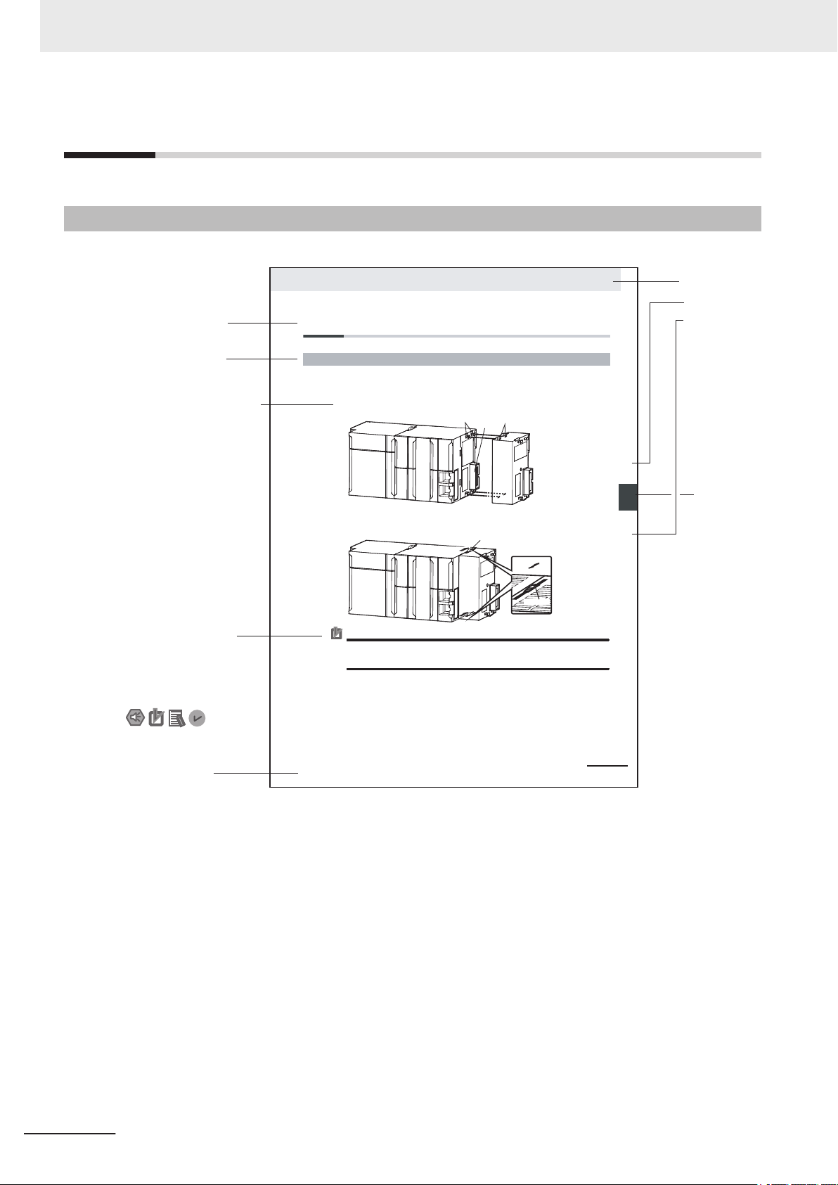
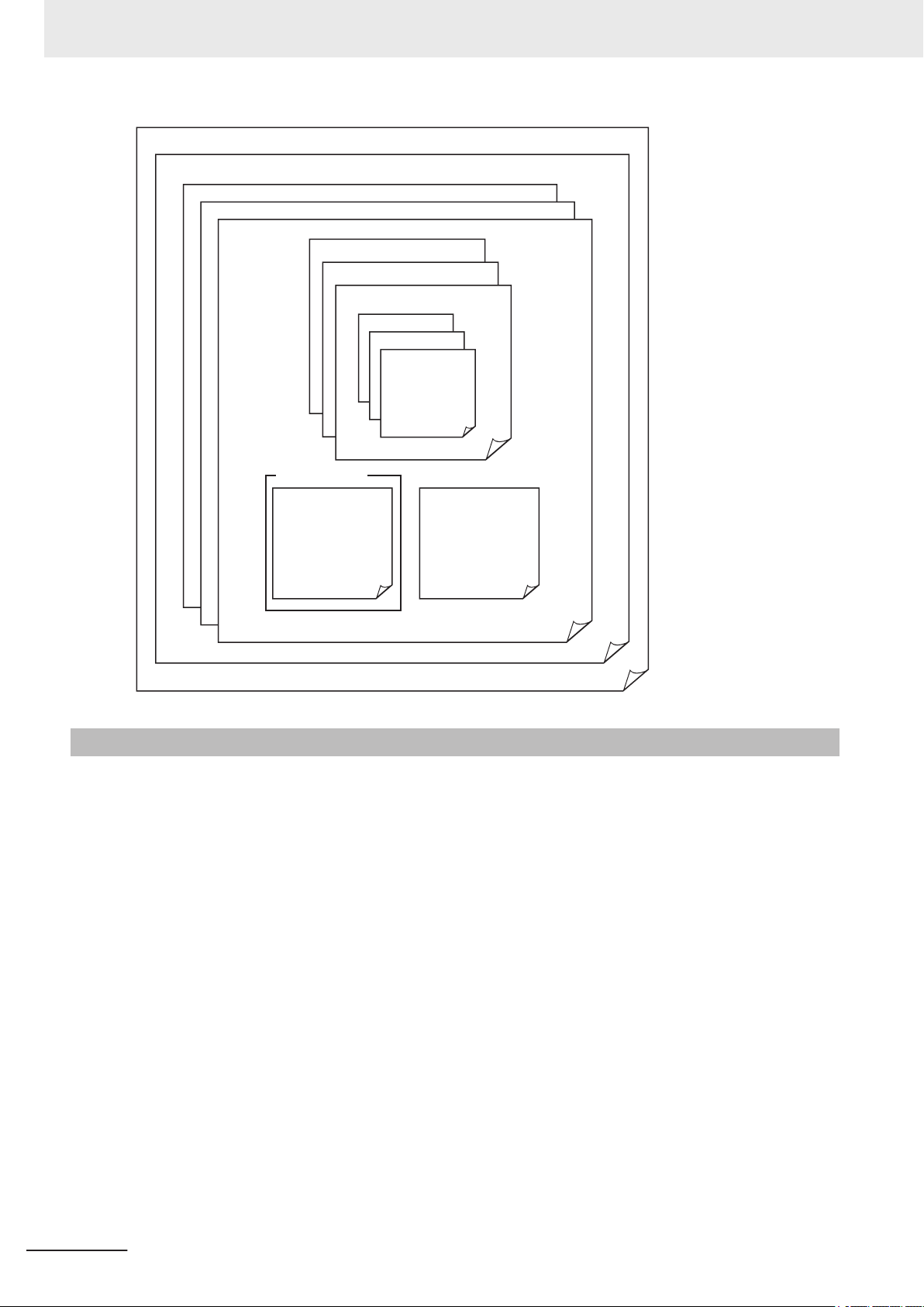
Level 1 heading
Level 2 heading
Level 3 heading
Level 2 heading
A step in a procedure
Manual name
Special information
Level 3 heading
Page tab
Gives the current
headings.
Indicates a procedure.
Icons indicate
precautions, additional
information, or reference
information.
Gives the number
of the main section.
The sliders on the tops and bottoms of the Power Supply Unit, CPU Unit, I/O Units, Special I/O
Units, and CPU Bus Units must be completely locked (until they click into place) after connecting
the adjacent Unit connectors.
Manual Structure
Manual Structure
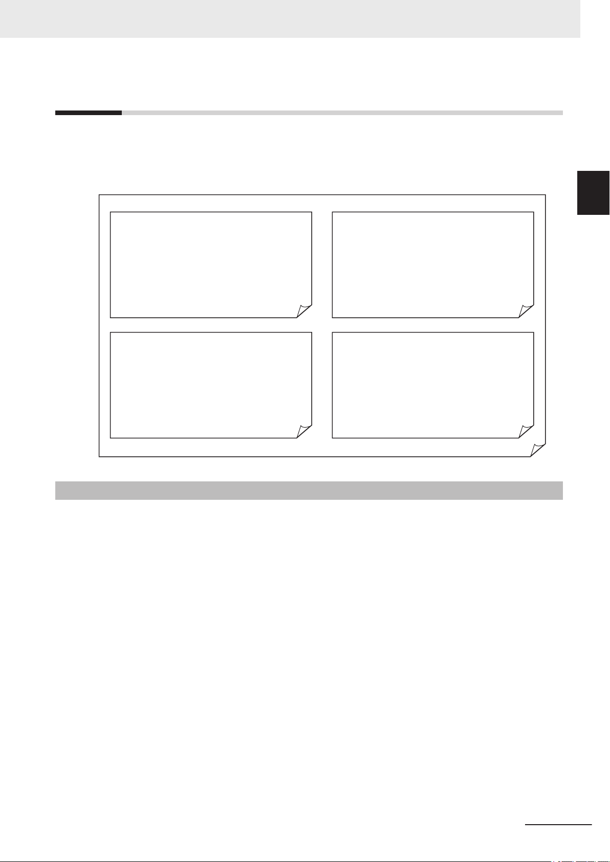
Page Structure
The following page structure is used in this manual.
Note This illustration is provided only as a sample. It may not literally appear in this manual.
4
FH/FHV Series Vision System Operation Manual for Sysmac Studio (Z343-E1)
Page 7

Special Information
Special information in this manual is classified as follows:
Precautions for Safe Use
Precautions on what to do and what not to do to ensure safe usage of the product.
Precautions for Correct Use
Precautions on what to do and what not to do to ensure proper operation and performance.
Additional Information
Additional information to read as required.
This information is provided to increase understanding or make operation easier
Manual Structure
.
FH/FHV Series Vision System Operation Manual for Sysmac Studio (Z343-E1)
5
Page 8

Manual Structure
6
FH/FHV Series Vision System Operation Manual for Sysmac Studio (Z343-E1)
Page 9

CONTENTS
Introduction .............................................................................................................. 1
Intended Audience
Applicable Products ......................................................................................................................................... 1
Relevant Manuals..................................................................................................... 2
Manual Structure...................................................................................................... 4
Page Structure.................................................................................................................................................4
Special Information .......................................................................................................................................... 5
Terms and Conditions Agreement........................................................................ 11
Warranty, Limitations of Liability .................................................................................................................... 11
Application Considerations ............................................................................................................................12
Disclaimers ....................................................................................................................................................12
Safety Precautions................................................................................................. 14
CONTENTS
...........................................................................................................................................1
Precautions for Safe Use ...................................................................................... 15
Precautions for Correct Use ................................................................................. 16
Regulations and Standards .................................................................................. 17
Related Manuals..................................................................................................... 18
Terminology............................................................................................................ 20
Revision History..................................................................................................... 21
Sections in This Manual ........................................................................................ 23
Section 1 Overview
1-1 Supported Models................................................................................................................1 - 2
Project Management............................................................................................................1 - 3
1-2
1-2-1 Project data ...............................................................................................................................1 - 3
1-2-2 Project Data Handling in Different System Configurations........................................................1 - 4
Section 2 Basic Operations
2-1 Basic Design Flow 1 ............................................................................................................2 - 3
Basic Design Flow 2 ............................................................................................................2 - 5
2-2
2-3 Creating a New Project........................................................................................................2 - 7
2-3-1 Creating a New Project File from the Project Window ..............................................................2 - 7
2-3-2 Adding FH/FHV Device to a Project..........................................................................................2 - 8
2-3-3 Deleting FH/FHV Device from a Project....................................................................................2 - 9
2-4 Description of Screen Components.................................................................................2 - 10
2-4-1 Application Window.................................................................................................................2 - 10
2-4-2 Menu Bar.................................................................................................................................2 - 10
2-4-3 Toolbar .................................................................................................................................... 2 - 11
FH/FHV Series Vision System Operation Manual for Sysmac Studio (Z343-E1)
7
Page 10

CONTENTS
2-5 Basic Operations of Scene Data.......................................................................................2 - 31
2-6 Basic Operations of Flow Editing.....................................................................................2 - 35
2-7 Function List ......................................................................................................................2 - 39
2-8 Precautions on Synchronization through an NJ/NX/NY-series Controller...................2 - 44
2-4-4 Multiview Explorer ...................................................................................................................2 - 11
2-4-5
2-4-6 Toolbox ....................................................................................................................................2 - 29
2-5-1 Switching Scenes....................................................................................................................2 - 31
2-5-2 Managing Scenes ...................................................................................................................2 - 32
2-5-3 Entering Scene Information.....................................................................................................2 - 32
2-5-4 Searching for a Scene.............................................................................................................2 - 33
2-5-5 Switching Scene Groups.........................................................................................................2 - 33
2-5-6 Managing Scene Groups ........................................................................................................2 - 33
2-5-7 Entering Scene Group Information..........................................................................................2 - 34
2-6-1 Adding a Processing Unit........................................................................................................2 - 35
2-6-2 Managing Processing Units ....................................................................................................2 - 36
2-6-3 Searching for a Processing Unit..............................................................................................2 - 38
2-7-1 List of Functions Provided with the FH/FHV Tool ....................................................................2 - 39
2-7-2 Comparison with FH Series Unit Functions ............................................................................2 - 41
2-7-3 Comparison with FHV Series Unit Functions ..........................................................................2 - 42
2-8-1 Synchronized Project Data......................................................................................................2 - 44
2-8-2 Saving and Loading the Settings Data for the FH/FHV Sensor Controller..............................2 - 45
2-8-3 Transferring Data from the Sysmac Studio .............................................................................2 - 46
2-8-4 Transferring Data to the Sysmac Studio .................................................................................2 - 47
Edit Pane.................................................................................................................................2 - 13
Section 3 Connecting with a Vision Sensor
3-1 Connecting with a Vision Sensor ....................................................................................... 3 - 2
3-2
Adding FH/FHV Series Vision Sensor on the Network to a Project ................................3 - 3
3-3 Establishing an Online Connection with a Vision Sensor ...............................................3 - 4
3-3-1 Establishing an Online Connection from the Sensor Connection Screen .................................3 - 4
3-3-2 Establishing an Online Connection from the Multiview Explorer...............................................3 - 5
3-4 Synchronizing Project Data and Sensor Setting Data......................................................3 - 7
3-4-1 Transferring Project Data to the Sensor....................................................................................3 - 7
3-4-2 Transferring Setting data in the Sensor to a Project .................................................................3 - 8
3-5 Ending a Connection with a Vision Sensor.....................................................................3 - 10
3-5-1 Ending a Connection in the Sensor Connection Screen .........................................................3 - 10
3-5-2 Ending a Connection in the Multiview Explorer.......................................................................3 - 10
3-6 Logging in to a Registered User's Account ....................................................................3 - 11
Section 4 Configuring Measurement Settings
4-1 Overview of Processing Units ............................................................................................4 - 2
4-1-1
4-1-2 Measurement ............................................................................................................................4 - 2
4-1-3 Compensate Image...................................................................................................................4 - 2
4-1-4 Support Measurement...............................................................................................................4 - 3
4-1-5 Branch.......................................................................................................................................4 - 3
4-1-6 Output Result ............................................................................................................................4 - 3
4-1-7 Display Result ...........................................................................................................................4 - 3
4-2 Editing a Processing Unit ...................................................................................................4 - 5
4-2-1 Parameter Settings ...................................................................................................................4 - 5
4-2-2 Editing an Area..........................................................................................................................4 - 7
4-2-3 Color Extraction.......................................................................................................................4 - 10
4-2-4 Color........................................................................................................................................ 4 - 11
4-2-5 Binary ......................................................................................................................................4 - 11
Input Image ...............................................................................................................................4 - 2
8
FH/FHV Series Vision System Operation Manual for Sysmac Studio (Z343-E1)
Page 11

4-2-6 Detection Point/Reference Point .............................................................................................4 - 11
4-2-7
4-2-8 Image Control Area .................................................................................................................4 - 12
List...........................................................................................................................................4 - 12
Section 5 Designing Exchange with External Devices
5-1 Designing Exchange with External Devices......................................................................5 - 2
5-2
Setting Procedure ................................................................................................................ 5 - 3
Section 6 Online Debugging
6-1 Performing Test Measurement ...........................................................................................6 - 2
6-1-1
6-1-2 Measuring File Images in the RAMDisk or the External Memory, i.e. USB Memory of
6-1-3 Measuring Logging Images in the Vision Sensor Memory........................................................6 - 3
6-2 Checking Measurement Results.........................................................................................6 - 4
6-2-1 Checking Detailed Results ........................................................................................................6 - 4
6-2-2 Changing the Image Display Settings .......................................................................................6 - 5
6-2-3 Checking Multiple Measurement Images at the Same Time.....................................................6 - 6
6-3 Checking Result Output ...................................................................................................... 6 - 7
6-4 Saving Measurement Results ............................................................................................. 6 - 8
6-5 Saving Settings Data ...........................................................................................................6 - 9
6-6 Loading Settings Data ....................................................................................................... 6 - 10
Measuring Camera Images.......................................................................................................6 - 2
the Vision Sensor ......................................................................................................................6 - 3
CONTENTS
Section 7 Offline Debugging
7-1 Performing Offline Simulation of Sensor Measurement Operation ................................7 - 2
7-2 Offline Debugging of the Sensor Control Program and Sensor Operation (Only
When Using EtherCAT Connection) ...................................................................................7 - 3
7-2-1 Control Signals Supported with Offline Debugging ...................................................................7 - 3
7-2-2 Offline Debugging Procedure for the Sensor Control Program.................................................7 - 4
Section 8 Other Useful Functions
8-1 Using the Command Customize Setting Tool ...................................................................8 - 2
Using the Calibration Support Tool....................................................................................8 - 3
8-2
8-3 Using the File Save Tool......................................................................................................8 - 4
8-3-1 Opening the File Save Tool .......................................................................................................8 - 4
8-3-2 Copying a File ...........................................................................................................................8 - 4
8-3-3 Saving a Logging Image as a File.............................................................................................8 - 5
8-4 Using the User Data Setting Tool .......................................................................................8 - 6
8-5 Changing the System Environment ...................................................................................8 - 7
8-6 Help .......................................................................................................................................8 - 9
8-7 Using the Security Setting Tool ........................................................................................8 - 10
8-8 Using the Scene Group Saving Destination Setting Tool .............................................. 8 - 11
8-9 Using the Image File Save Tool ........................................................................................8 - 12
8-9-1 Opening the Image File Save Tool ..........................................................................................8 - 12
8-9-2 Saving the Image File .............................................................................................................8 - 12
FH/FHV Series Vision System Operation Manual for Sysmac Studio (Z343-E1)
9
Page 12

CONTENTS
8-9-3 Saving the Logged Images to Files.........................................................................................8 - 13
8-10
Using the Registered image Manager..............................................................................8 - 15
8-11 Using the Update Standard Position Tool .......................................................................8 - 16
8-12 Using the Conversion Scene Group Data Tool ...............................................................8 - 17
8-13 Using the Scene Control Macro Tool ...............................................................................8 - 18
8-14 Print the Settings ...............................................................................................................8 - 19
8-15 Using the Conveyor Panorama Display tool ...................................................................8 - 20
8-16 Using the Conveyor Calibration Wizard tool...................................................................8 - 21
8-17 Using the Calibration Plate Print tool ..............................................................................8 - 22
Section 9 Limitations
9-1 Limitations............................................................................................................................9 - 2
9-2
Synchronization with the NJ/NX/NY-series Controllers ................................................... 9 - 8
Section 10 Troubleshooting
10-1 Troubleshooting for EtherCAT.......................................................................................... 10 - 2
10-2
Sysmac Error Status..........................................................................................................10 - 3
Appendices
A-1 Sysmac Device Features.................................................................................................... A - 2
A-1-1 Sysmac Error Status ................................................................................................................ A - 2
A-1-2 Saving the Node Address Setting ............................................................................................ A - 2
A-1-3 Serial Number Display ............................................................................................................. A - 3
A-1-4 Compliance with ESI Specification (ETG.2000 S (R) V1.0.1) .................................................. A - 3
A-1-5 SII Data Check ......................................................................................................................... A - 3
Index
10
FH/FHV Series Vision System Operation Manual for Sysmac Studio (Z343-E1)
Page 13

Terms and Conditions Agreement
Terms and Conditions Agreement
Warranty, Limitations of Liability
Warranties
Exclusive Warranty
l
Omron’s exclusive warranty is that the Products will be free from defects in materials and work-
manship for a period of twelve months from the date of sale by Omron (or such other period ex-
pressed in writing by Omron). Omron disclaims all other warranties, express or implied.
Limitations
l
OMRON MAKES NO WARRANTY OR REPRESENTATION, EXPRESS OR IMPLIED, ABOUT
NON-INFRINGEMENT, MERCHANTABILITY OR FITNESS FOR A PARTICULAR PURPOSE OF
THE PRODUCTS. BUYER ACKNOWLEDGES THAT IT ALONE HAS DETERMINED THAT THE
PRODUCTS WILL SUITABLY MEET THE REQUIREMENTS OF THEIR INTENDED USE.
Omron further disclaims all warranties and responsibility of any type for claims or expenses based
on infringement by the Products or otherwise of any intellectual property right.
Buyer Remedy
l
Omron’s sole obligation hereunder shall be, at Omron’s election, to (i) replace (in the form originally
shipped with Buyer responsible for labor charges for removal or replacement thereof) the non-com-
plying Product, (ii) repair the non-complying Product, or (iii) repay or credit Buyer an amount equal
to the purchase price of the non-complying Product; provided that in no event shall Omron be re-
sponsible for warranty, repair, indemnity or any other claims or expenses regarding the Products
unless Omron’s analysis confirms that the Products were properly handled, stored, installed and
maintained and not subject to contamination, abuse, misuse or inappropriate modification. Return
of any Products by Buyer must be approved in writing by Omron before shipment. Omron Compa-
nies shall not be liable for the suitability or unsuitability or the results from the use of Products in
combination with any electrical or electronic components, circuits, system assemblies or any other
materials or substances or environments. Any advice, recommendations or information given orally
or in writing, are not to be construed as an amendment or addition to the above warranty.
See http://www.omron.com/global/ or contact your Omron representative for published information.
Limitation on Liability; Etc
OMRON COMPANIES SHALL NOT BE LIABLE FOR SPECIAL, INDIRECT, INCIDENTAL, OR CON-
SEQUENTIAL DAMAGES, LOSS OF PROFITS OR PRODUCTION OR COMMERCIAL LOSS IN ANY
FH/FHV Series Vision System Operation Manual for Sysmac Studio (Z343-E1)
11
Page 14

Terms and Conditions Agreement
WAY CONNECTED WITH THE PRODUCTS, WHETHER SUCH CLAIM IS BASED IN CONTRACT,
W
ARRANTY, NEGLIGENCE OR STRICT LIABILITY.
Further, in no event shall liability of Omron Companies exceed the individual price of the Product on
which liability is asserted.
Application Considerations
Suitability of Use
Omron Companies shall not be responsible for conformity with any standards, codes or regulations
which apply to the combination of the Product in the Buyer
er’s request, Omron will provide applicable third party certification documents identifying ratings and
limitations of use which apply to the Product. This information by itself is not sufficient for a complete
determination of the suitability of the Product in combination with the end product, machine, system, or
other application or use. Buyer shall be solely responsible for determining appropriateness of the par-
ticular Product with respect to Buyer’s application, product or system. Buyer shall take application re-
sponsibility in all cases.
’s application or use of the Product. At Buy-
NEVER USE THE PRODUCT FOR AN APPLICATION INVOLVING SERIOUS RISK TO LIFE OR
PROPERTY OR IN LARGE QUANTITIES WITHOUT ENSURING THAT THE SYSTEM AS A WHOLE
HAS BEEN DESIGNED TO ADDRESS THE RISKS, AND THAT THE OMRON PRODUCT(S) IS
PROPERLY RATED AND INSTALLED FOR THE INTENDED USE WITHIN THE OVERALL EQUIP-
MENT OR SYSTEM.
Programmable Products
Omron Companies shall not be responsible for the user’s programming of a programmable Product, or
any consequence thereof.
Disclaimers
Performance Data
Data presented in Omron Company websites, catalogs and other materials is provided as a guide for
the user in determining suitability and does not constitute a warranty
Omron’s test conditions, and the user must correlate it to actual application requirements. Actual per-
formance is subject to the Omron’s Warranty and Limitations of Liability.
. It may represent the result of
12
Change in Specifications
Product specifications and accessories may be changed at any time based on improvements and oth-
er reasons. It is our practice to change part numbers when published ratings or features are changed,
or when significant construction changes are made. However
FH/FHV Series Vision System Operation Manual for Sysmac Studio (Z343-E1)
, some specifications of the Product may
Page 15

Terms and Conditions Agreement
be changed without any notice. When in doubt, special part numbers may be assigned to fix or estab-
lish key specifications for your application. Please consult with your Omron’
time to confirm actual specifications of purchased Product.
s representative at any
Errors and Omissions
Information presented by Omron Companies has been checked and is believed to be accurate; how-
ever
, no responsibility is assumed for clerical, typographical or proofreading errors or omissions.
FH/FHV Series Vision System Operation Manual for Sysmac Studio (Z343-E1)
13
Page 16

Safety Precautions
Safety Precautions
For details of Safety Precautions, refer to Safety Precautions in the Vision System FH/FHV Series Us-
er's Manual (Cat. No. Z365).
14
FH/FHV Series Vision System Operation Manual for Sysmac Studio (Z343-E1)
Page 17

Precautions for Safe Use
For details of Precautions for Safe Use, refer to Precautions for Safe Use in the Vision System
FH/FHV Series User's Manual (Cat. No. Z365).
Precautions for Safe Use
FH/FHV Series Vision System Operation Manual for Sysmac Studio (Z343-E1)
15
Page 18

Precautions for Correct Use
Precautions for Correct Use
For details of Precautions for Correct Use, refer to Precautions for Correct Use in the Vision System
FH/FHV Series User's Manual (Cat. No. Z365).
16
FH/FHV Series Vision System Operation Manual for Sysmac Studio (Z343-E1)
Page 19

Regulations and Standards
For details of Regulations and Standards, refer to Regulations and Standards in the Vision System
FH/FHV Series User's Manual (Cat. No. Z365).
Regulations and Standards
FH/FHV Series Vision System Operation Manual for Sysmac Studio (Z343-E1)
17
Page 20

Related Manuals
Related Manuals
The followings are the manuals related to this manual. Use these manuals for reference.
Name of Manual Cat. No.. Model Purpose Contents
Vision System
FH Instruction Sheet
Vision System
FH Instruction Sheet
Vision System
FH-L Instruction Sheet
Smart Camera
FHV Instruction Sheet
Smart Camera
Lighting Module
-LTM Instruction Sheet
FHV
Smart Camera Lens Module
-LEM-S Instruction
FHV
Sheet
Smart Camera High-Speed
Lens Module
-LEM-H Instruction
FHV
Sheet
Smart Camera Data Unit
FHV Instruction Sheet
FHV Series
Smart Camera
Setup Manual
9608337-2
3102269-4
9606631-1
3129404-0
3129276-4
3128622-5
3129408-2
3130057-0
Z408
FH-1£££
FH-1£££-££
FH-3£££
FH-3£££-££
FH-2£££
FH-2£££-££
FH-5£££
FH-5£££-££
FH-L£££
FH-L£££-££
FHV7£-£££££-C
FHV-LTM££
FHV-LEM-S££
FHV-LEM-H££
FHV-SDU££
FHV7£-£££££-C
FHV7£-£££££-S££
FHV7£-£££££-S££-£
£
FHV7£-£££££-H££
FHV7£-£££££-H££-£
£
To confirm the safety
and usage precautions of the V
System FH series
Sensor Controller.
To confirm the safety
and usage precautions of the V
System FH series
Sensor Controller.
To confirm the safety
and usage precautions of the V
System FH-Lite series Sensor Controller.
To confirm the safety
and usage precautions of the Smart
Camera FHV7 series.
To confirm the safety
and usage precautions of the Smart
camera lighting module FHV-LTM.
To confirm the safety
and usage precautions of the Smart
camera lens module
FHV-LEM-S.
To confirm the safety
and usage precautions of the Smart
camera high-speed
lens module FHVLEM-H.
To confirm the safety
and usage precautions of the Smart
Camera Data Unit.
When User want to
know about the hardware specifications
or to setup the Smart
camera FHV series.
ision
ision
ision
Describes the definitions of basic
terms, meaning of signal words, and
precautions for correct use of FH
series in the manual.
To confirm the safety and usage precautions of the Vision System FH
series Sensor Controller.
Describes the definitions of basic
terms, meaning of signal words, and
precautions for correct use of FH-L
series in the manual.
Describes the definitions of basic
terms, the meaning of signal words,
and precautions for correct use of
FHV7 series in the manual.
Describes the definitions of basic
terms, the meaning of signal words,
and precautions for correct use of
the lighting module FHV-LTM in the
manual.
Describes the definitions of basic
terms, the meaning of signal words,
and precautions for correct use of
the lens module FHV-LEM-S.
Describes the definitions of basic
terms, the meaning of signal words,
and precautions for correct use of
the high-speed lens module FHVLEM-H.
Describes the definitions of basic
terms, the meaning of signal words,
and precautions for correct use of
the Smart Camera Data Unit in the
manual.
Describes FHV series specifications,
dimensions, part names, I/O information, installation information, and
wiring information.
18
FH/FHV Series Vision System Operation Manual for Sysmac Studio (Z343-E1)
Page 21

Name of Manual Cat. No.. Model Purpose Contents
Vision System
FH/FHV Series
User's Manual
Vision System
FH/FHV/FZ5 series
Processing Item Function
Reference Manual
Vision System
FH/FHV/FZ5 Series
User's manual for Communications Settings
Vision System
FH/FZ5 series
Hardware Setup Manual
Vision System
FH series
Macro Customize Functions Programming Manual
Vision System
FH/FHV Series
Operation Manual
for Sysmac Studio
Z365
Z341 When User confirm
Z342 When User confirm
Z366
Z367 When User operate
Z343
FH-1£££
FH-1£££-££
FH-2£££
FH-2£££-££
FH-3£££
FH-3£££-££
FH-5£££
FH-5£££-££
FH-L£££
FH-L£££-££
FHV7£-£££££-C
FHV7£-£££££-S££
FHV7£-£££££-S££-£
£
FHV7£-£££££-H££
FHV7£-£££££-H££-£
£
FH-1£££
FH-1£££-££
FH-2£££
FH-2£££-££
FH-3£££
FH-3£££-££
FH-5£££
FH-5£££-££
FH-L£££
FH-L£££-££
FH-1£££
FH-1£££-££
FH-2£££
FH-2£££-££
FH-3£££
FH-3£££-££
FH-5£££
FH-5£££-££
FHV7£-£££££-C
FHV7£-£££££-S££
FHV7£-£££££-S££-£
£
FHV7£-£££££-H££
FHV7£-£££££-H££-£
£
When User want to
know about the
FH/FHV series.
the details of each
processing items at
the create the measurement flow or operate it.
the setting of communication functions.
When User want to
know about the
Hard-ware specifications or to setup the
Sensor Controller of
ision System
the V
FH/FZ5 series.
or programming using Macro Customize
functions.
When User connect
to NJ series via
T communi-
EtherCA
cation.
Describes the soft functions, setup,
and operations to use FH/FHV series/
Describes the software functions,
settings, and operations for using
FH/FHV/FZ5 series.
Describes the functions, settings,
and communications methods for
communication between
FH/FHV/FZ5 series and PLCs.
The following communications protocol are described.
Parallel, PLC Link, EtherNet/IP
EtherCAT, and Non-procedure.
Describes FH/FZ5 series specifications, dimensions, part names, I/O
information, installation information,
and wiring information.
Describes the functions, settings,
and operations for using Macro Customize function of the FH series.
Describes the operating procedures
for setting up and operating FH/FHV
series Vision Sensors from the Sysmac Studio FH/FHV Tools.
Related Manuals
,
FH/FHV Series Vision System Operation Manual for Sysmac Studio (Z343-E1)
19
Page 22

Terminology
Terminology
• For descriptions of the Controller terms that are used in this manual, refer to information on terminol-
ogy in the Sysmac Studio Version 1 Operation Manual (Cat. No. W504).
• For descriptions of the FH/FHV Series terms that are used in this manual, refer to information on
terminology in the FH/FHV Series Vision System User's Manual (Cat. No. Z365).
20
FH/FHV Series Vision System Operation Manual for Sysmac Studio (Z343-E1)
Page 23
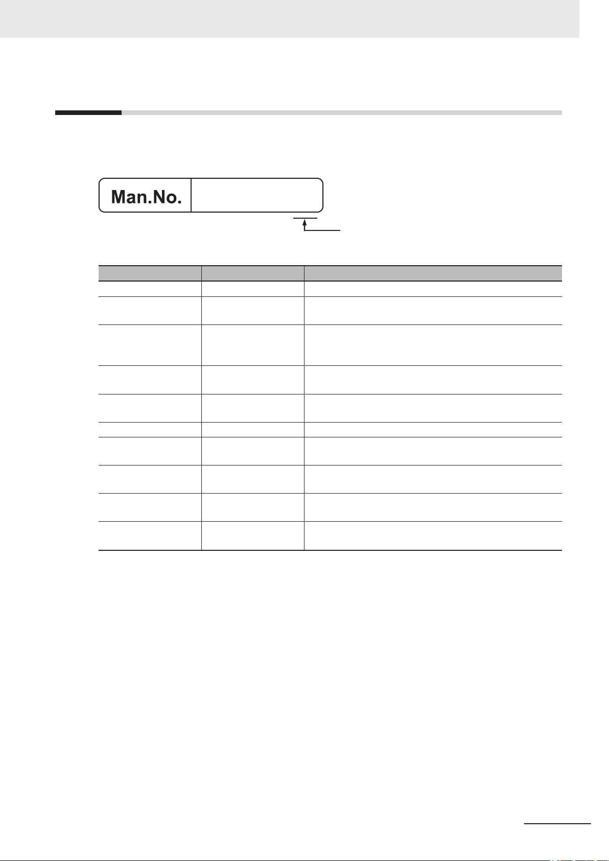
Revision History
Z343-E1-10
Revision Code
A manual revision code appears as a suffix to the catalog number on the front and back covers of the
manual.
Rev. Code Rev. Date Revision Contents
01 Jun. 2013 First edition.
02 Sep 2013 Added offline debugging function, Support for software ver-
03 Jan. 2014 Added additional supported processing units, added support
04 Jul. 2014 Additions for software version upgrade. Support for software
05 Oct. 2015 Additions for software version upgrade and FH Sensor Con-
06 Apr. 2016 Corrections sentences related other manuals.
07 Apr. 2017 Additions for software version upgrade and FH Sensor Con-
08 Jun. 2017 Additions for software version upgrade and FH Sensor Con-
09 Jul. 2018 Additions for software version upgrade and FH Sensor Con-
10 Oct. 2019 Additions for software version upgrade, FHV Smart Camera
Revision History
sion 5.1 of the FH sensor controller
for multiple FH unit settings, added a security function, expanded data transfer functions.
version 5.20 of the FH sensor controller
troller ver
troller ver
troller ver
troller ver
ver
.5.50.
.5.71.
.5.72.
.6.10.
.6.30 and FH Sensor Controller ver.6.20, 6.30.
.
.
FH/FHV Series Vision System Operation Manual for Sysmac Studio (Z343-E1)
21
Page 24

Revision History
22
FH/FHV Series Vision System Operation Manual for Sysmac Studio (Z343-E1)
Page 25
Sections in This Manual
1
10
2
3
4
5
6
7
8
9
1
10
2
3
A
I
4
5
6
7
8
9
Overview Troubleshooting
Basic Operations Appendices
Connecting with
a Vision Sensor
A
I
Index
Designing Exchange with External Devices
Configuring Measurement Settings
Online Debugging
Offline Debugging
Other Useful Functions
Limitations
Sections in This Manual
FH/FHV Series Vision System Operation Manual for Sysmac Studio (Z343-E1)
23
Page 26

Sections in This Manual
24
FH/FHV Series Vision System Operation Manual for Sysmac Studio (Z343-E1)
Page 27

Overview
This Chapter describes the functional specifications of the Sysmac Studio FH/FHV
tools (hereinafter referred to as "FH/FHV tools").
1-1
1-2 Project Management ....................................................................................1 - 3
1
Supported Models........................................................................................ 1 - 2
1-2-1 Project data................................................................................................... 1 - 3
1-2-2 Project Data Handling in Different System Configurations ........................... 1 - 4
1
FH/FHV Series Vision System Operation Manual for Sysmac Studio (Z343-E1)
1 - 1
Page 28

1 Overview
1-1
Supported Models
The FH/FHV tools support the following models in the FH/FHV Vision Sensor series.
Connection Device Type Description
FH-5050 High-speed controller for 2-channel camera type
FH-5050-10 High-speed controller for 4-channel camera type
FH-5050-20 High-speed controller for 8-channel camera type
FH-3050 High-speed controller for 2-channel camera type
FH-3050-10 High-speed controller for 4-channel camera type
FH-3050-20 High-speed controller for 8-channel camera type
FH-2050 High-speed controller for 2-channel camera type
FH-2050-10 High-speed controller for 4-channel camera type
FH-2050-20 High-speed controller for 8-channel camera type
FH-1050 Standard controller for 2-channel camera type
FH-1050-10 Standard controller for 4-channel camera type
FH-1050-20 Standard controller for 8-channel camera type
FHV7£-£££££-C
FHV7£-£££££-S££
FHV7£-£££££-S££-££
FHV7£-£££££-H££
FHV7£-£££££-H££-££
Smart Camera
1 - 2
FH/FHV Series Vision System Operation Manual for Sysmac Studio (Z343-E1)
Page 29
Project data
Data related to the NJ/NX/NY-series Controller Data related to the FH/FHV sensor
Data related to Servo Drives Data related to other vision sensors
1 Overview
1-2 Project Management
1-2
Project Management
Sysmac Studio manages the configuration information of each of the controller, servo, and vision sen-
sor devices on a project basis.
Here, we describe the contents of the project data related to the FH/FHV Series and how the data is
managed.
1
1-2-1 Project data
1-2-1
Project data
Eight FH/FHV vision sensor series devices can be registered to one project.
In the FH/FHV Series, the following types of data provided by Sysmac Studio are managed as project
data.
Scene group data (scene data)
•
• System data
• Tool data (communications command macros, security settings, and other data)
By using the Multi-line Random-trigger Mode, the FH sensor controller independently processes multi-
ple processing lines at the same time. In Multi-line Random Trigger mode, the above data is controlled
separately for each line. (It can not be used with the FHV series.)
Project data manages this data together as one batch. These data can also be exported and imported
individually as file data.
FH/FHV Series Vision System Operation Manual for Sysmac Studio (Z343-E1)
1 - 3
Page 30
Sensor
Line
Project data
Line
Line
Scene group data
Scene group data
Command
customize
data
System
data
Tool data
Scene data
Scene group data
Scene data
Scene data
1 Overview
1-2-2
Project Data Handling in Different System Configurations
The contents of the Sysmac Studio project data and the data being synchronized varies depending on
the connection method (i.e., Ethernet direct connection or connection through an NJ/NX/NY
Controller) between the FH/FHV sensor and the computer that runs Sysmac Studio. Particularly with
the connection through an NJ/NX/NY-series Controller, there are restrictions on some Sysmac Studio
functions. Be sure you understand the following before operation.
For details, refer to the 2-8 Precautions on Synchronization through an NJ/NX/NY-series Controller on
page 2 - 44.
-series
1 - 4
FH/FHV Series Vision System Operation Manual for Sysmac Studio (Z343-E1)
Page 31

USB/Ethernet
EtherCAT
Sysmac Studio NJ/NX/NY-series Controller
FH/FHV
Ethernet
Sysmac Studio
FH/FHV
Configurations and Setup
Configurations and Setup
EtherCAT
CPU/Expansion
Racks
POUs Data
System data
Tool data
Tasks
I/O Map
Controller Setup
Task SetupEvent Setup
Motion Control
Setup
Cam Data
Settings
Scene group
data
Data that the NJ/NX/NY-series
Controller manages
Data that the FH/FHV
sensor manages
Project data
System data
Tool data
Scene group
data
Data that the FH/FHV
sensor manages
Project data
1 Overview
1-2 Project Management
System configuration
Project data that the
Sysmac Studio
manages
Connection through an NJ/NX/NY-series
Controller (when executing an
NJ/NX/NY project)
The sensor data unit (FHV-SDU30) is required for EtherCA
T connection between
NJ/NX/NY-series Controller and FHV sensor.
For details, refer to FHV Series Smart
Camera Setup Manual (Cat. No. Z408).
There are two types of data: the data that
the NJ/NX/NY
-series Controller manages
and the data that the FH/FHV sensor manages.
Ethernet direct connection
(when executing an FH/FHV project)
1
1-2-2 Project Data Handling in Different System Configurations
There is the data that the FH/FHV sensor
manages.
Data to be
synchronized with
Sysmac Studio
Available functions
in Sysmac Studio
that control the
FH/FHV sensor
Online
Available functions
FH/FHV Series Vision System Operation Manual for Sysmac Studio (Z343-E1)
in Sysmac Studio
that control the
FH/FHV sensor
fline
Of
The data that the NJ/NX/NY-series Controller manages within the project data that
Sysmac Studio manages is synchronized.
Because the data that the FH/FHV sensor
manages (i.e., the settings data for the
FH/FHV sensor) is not synchronized, the
settings for the FH/FHV sensor need to be
synchronized separately
.
For details, refer to the 2-8 Precautions on
Synchronization through an NJ/NX/NY-series Controller on page 2 - 44.
Checking the data output from the FH/FHV
sensor sent through EtherCA
T is possible.
Making setting changes, and creating and
adjusting the measurement flows for the
FH/FHV are not possible.
Checking the data output from the FH/FHV
sensor sent through EtherCAT is possible.
Making setting changes on the FH/FHV
sensor, creating and adjusting the measurement flows for the FH/FHV in addition to
checking the output data from the FH/FHV
sensor are all possible.
The data that the FH/FHV sensor manages
(i.e., the settings data for the FH/FHV sensor) within the project data that Sysmac
Studio manages is synchronized.
For details, refer to the 3-4 Synchronizing
Project Data and Sensor Setting Data on
page 3 - 7.
Making setting changes on the FH/FHV
sensor, creating and adjusting the measurement flows for the FH/FHV in addition to
checking the output data from the FH/FHV
sensor are all possible.
Making setting changes on the FH/FHV
sensor, creating and adjusting the measurement flows for the FH/FHV in addition to
checking the output data from the FH/FHV
sensor are all possible.
1 - 5
Page 32

1 Overview
Downloading the
settings data for the
FH/FHV sensor
Uploading the settings data for the
FH/FHV sensor
Connection through an NJ/NX/NY-series
Controller (when executing an
NJ/NX/NY project)
The settings data for the FH/FHV sensor is
not downloaded.
Performing the data downloading from
Sysmac Studio will not download the data
that the FH/FHV sensor manages within
the project data that Sysmac Studio manages. Therefore, the settings for the
FH/FHV sensor will not be overwritten.
There are following two methods to download the FH/FHV settings data to the
FH/FHV sensor
.
• Directly connecting to the FH/FHV sen-
sor and downloading the data.
• Extracting the data from Sysmac Studio
and loading it to the FH/FHV sensor via
the external memory.
The settings data for the FH/FHV sensor is
not uploaded.
After performing the data uploading to Sysmac Studio, all the FH/FHV settings data
values (i.e., the scene group data, the system data, the communications command
macros, and the security settings data) that
the FH/FHV sensor manages within the
project data that Sysmac Studio manages
will be reset to the factory defaults.
The device variables related to the FH/FHV
sensor in the I/O Map are uploaded.
There are following two methods to transfer the settings data for the FH/FHV sensor
to Sysmac Studio.
• Directly connecting to the FH/FHV sen-
sor and uploading the data.
• Save the settings data in the FH/FHV
sensor in the external memory and load
it to Sysmac Studio via the external
memory.
Ethernet direct connection
(when executing an FH/FHV project)
Downloading the FH/FHV settings data
from Sysmac Studio is possible.
If the FH/FHV sensor is connected to the
computer that runs Sysmac Studio via
Ethernet, downloading the FH/FHV settings
data from Sysmac Studio to the FH/FHV
sensor is possible by transferring the
project data that the Sysmac Studio manages to the FH/FHV sensor via the Ethernet.
If not connected, right-click the FH/FHV
sensor in the Multiview Explorer and select
Save file from the menu to save the data in
the external memory. Then, load the data
in the external memory to the FH/FHV sensor.
Uploading the settings data for the FH/FHV
sensor to Sysmac Studio is possible.
If the FH/FHV sensor is connected to the
computer that runs Sysmac Studio via
Ethernet, loading the data in the FH/FHV
sensor to Sysmac Studio project is possible by transferring the FH/FHV settings data to the project via Ethernet.
If not connected, connect the external
memory that holds the FH/FHV settings data to the computer that runs Sysmac Studio. Then, right-click the FH/FHV sensor in
the Multiview Explorer and select Load
from file from the menu to load the data.
1 - 6
FH/FHV Series Vision System Operation Manual for Sysmac Studio (Z343-E1)
Page 33

Configurations and Setup
Configurations and
Setup
EtherCAT
CPU/Expansion Racks
Data
System data
Tool data
Tasks
I/O Map
Controller Setup
Task Setup
Event Setup
Motion Control Setup
Cam Data Settings
Scene group data
Data that the NJ/NX/NY-series Controller manages
Data that the FH/FHV sensor manages
Project data
1 Overview
Precautions for Correct Use
The data that the NJ/NX/NY-series Controller manages and the data that the FH/FHV sensor
manages are handled separately on Sysmac Studio except for the I/O Map data that the
NJ/NX/NY
FH/FHV sensor manages. Because of this, the information in the I/O Map will be updated and
changed after editing the data that the FH/FHV sensor controller manages (i.e., the settings data for the FH/FHV sensor).
-series Controller manages. The I/O Map is associated to the system data that the
1-2 Project Management
1
1-2-2 Project Data Handling in Different System Configurations
FH/FHV Series Vision System Operation Manual for Sysmac Studio (Z343-E1)
1 - 7
Page 34

1 Overview
1 - 8
FH/FHV Series Vision System Operation Manual for Sysmac Studio (Z343-E1)
Page 35

2
2
Basic Operations
This chapter describes the basic design flow and design items for using Sysmac Studio.
Note:
•
The contents of the Sysmac Studio project data and the data being synchronized
varies depending on the connection method (i.e., Ethernet direct connection or connection through an NJ/NX/NY-series Controller) between the FH/FHV sensor and
the computer that runs Sysmac Studio.
• For information on connection through an NJ/NX/NY-series Controller, refer to
2-8 Precautions on Synchronization through an NJ/NX/NY-series Controller on page
2 - 44.
2-1 Basic Design Flow 1 .................................................................................... 2 - 3
2-2 Basic Design Flow 2 .................................................................................... 2 - 5
2-3 Creating a New Project ................................................................................2 - 7
2-3-1 Creating a New Project File from the Project Window.................................. 2 - 7
2-3-2 Adding FH/FHV Device to a Project ............................................................. 2 - 8
2-3-3 Deleting FH/FHV Device from a Project ....................................................... 2 - 9
2-4 Description of Screen Components ......................................................... 2 - 10
2-4-1 Application Window .................................................................................... 2 - 10
2-4-2 Menu Bar .................................................................................................... 2 - 10
2-4-3 Toolbar .........................................................................................................2 - 11
2-4-4 Multiview Explorer........................................................................................2 - 11
2-4-5 Edit Pane .................................................................................................... 2 - 13
2-4-6 Toolbox ....................................................................................................... 2 - 29
2-5 Basic Operations of Scene Data............................................................... 2 - 31
2-5-1 Switching Scenes ....................................................................................... 2 - 31
2-5-2 Managing Scenes ....................................................................................... 2 - 32
2-5-3 Entering Scene Information ........................................................................ 2 - 32
2-5-4 Searching for a Scene ................................................................................ 2 - 33
2-5-5 Switching Scene Groups ............................................................................ 2 - 33
2-5-6 Managing Scene Groups ............................................................................ 2 - 33
2-5-7 Entering Scene Group Information ............................................................. 2 - 34
2-6 Basic Operations of Flow Editing............................................................. 2 - 35
2-6-1 Adding a Processing Unit ........................................................................... 2 - 35
2-6-2 Managing Processing Units ........................................................................ 2 - 36
2-6-3 Searching for a Processing Unit ................................................................. 2 - 38
FH/FHV Series Vision System Operation Manual for Sysmac Studio (Z343-E1)
2 - 1
Page 36

2 Basic Operations
2-7 Function List............................................................................................... 2 - 39
2-7-1
2-7-2 Comparison with FH Series Unit Functions ................................................ 2 - 41
2-7-3 Comparison with FHV Series Unit Functions.............................................. 2 - 42
List of Functions Provided with the FH/FHV Tool ....................................... 2 - 39
2-8 Precautions on Synchronization through an NJ/NX/NY-series
Controller ..................................................................................................... 2 - 44
2-8-1 Synchronized Project Data ......................................................................... 2 - 44
2-8-2 Saving and Loading the Settings Data for the FH/FHV Sensor Controller . 2 - 45
2-8-3 Transferring Data from the Sysmac Studio................................................. 2 - 46
2-8-4 Transferring Data to the Sysmac Studio..................................................... 2 - 47
2 - 2
FH/FHV Series Vision System Operation Manual for Sysmac Studio (Z343-E1)
Page 37

2 Basic Operations
2-1
Basic Design Flow 1
This section describes the flow for designing a system that uses NJ/NX/NY-series CPU Unit as a con-
troller.
For details on the program on the NJ/NX/NY-series CPU Unit side, task design, and debugging, refer
to the Sysmac Studio Version 1 Operation Manual (Cat. No. W504).
Precautions for Correct Use
The settings data for the FH/FHV sensor cannot be synchronized with the data in the Sysmac
Studio project via an NJ/NX/NY-series Controller.
For details, refer to 2-8 Precautions on Synchronization through an NJ/NX/NY-series Controller
on page 2 - 44.
To synchronize them, directly connect the FH/FHV sensor to the computer that runs Sysmac
Studio via Ethernet.
For details, refer to 3-4 Synchronizing Project Data and Sensor Setting Data on page 3 - 7.
New project settings
Create a project file.
2-1 Basic Design Flow 1
2
(1) Starting Sysmac Studio
Start Sysmac Studio.
For details, refer to Starting and Exiting the Sysmac Studio in the Sysmac Studio Version 1
Operation Manual (Cat. No. W504).
(2) Designing a new project
Create a new project.
For details, refer to Creating a Project File in the Sysmac Studio Version 1 Operation Manual
(Cat. No. W504).
Controller configuration and settings
• Controller configuration:
Creating an EtherCAT configuration
(1)
Register FH/FHV as an EtherCAT slave in EtherCAT.
For details, refer to EtherCAT Configuration and Settings in the Sysmac Studio Version 1
Operation Manual (Cat. No. W504).
Registering device variables
(2)
When using or using after editing device variables for the user defined variables to connect the
FH/FHV I/O information and program, register the device variables in I/O Map.
For details, refer to Creating Device Variables in the Sysmac Studio Version 1 Operation
Manual (Cat. No. W504).
• Controller settings:
Editing slave parameters
(1)
Edit the Operation Settings of the slaves.
For details, refer to Creating the EtherCAT Slave Terminal Configuration in the Sysmac Studio
Version 1 Operation Manual (Cat. No. W504).
FH/FHV Series Vision System Operation Manual for Sysmac Studio (Z343-E1)
2 - 3
Page 38

2 Basic Operations
Sensor connection
Establish an online connection with the sensor.
(1) Connecting a sensor
For details, refer to S
Design
Create the processing flow.
(1) Creating flow
For details, refer to 2-6 Basic Operations of Flow Editing on page
(2) Editing processing units
For details, refer to 4-2 Editing a Processing Unit on page 4 - 5.
ection 3 Connecting with a Vision Sensor on page 3 - 1.
2 - 35.
Online debugging of sensor
Perform debugging using the actual device.
(1) Performing test measurement
Perform test measurement on sample work. Adjust the parameters if necessary
For details, refer to Section 6 Online Debugging on page 6 - 1.
.
2 - 4
FH/FHV Series Vision System Operation Manual for Sysmac Studio (Z343-E1)
Page 39

2 Basic Operations
2-2
Basic Design Flow 2
This section describes the flow for designing a system that uses a controller other than NJ/NX/NY-ser-
ies CPU Unit.
New project settings
Create a project file.
(1) Starting Sysmac Studio
Start Sysmac Studio.
For details, refer to Starting and Exiting the Sysmac Studio in the Sysmac Studio Version 1
Operation Manual (Cat. No. W504).
(2) Designing a new project
Create a new project.
Select a vision sensor for the category and FH/FHV for the device.
For details, refer to 2-3 Creating a New Project on page 2 - 7.
(3) Selecting sensor type
Select the sensor type and then establish an online connection.
For details, refer to the step 3 on 2-3-1 Creating a New Project File from the Project Window on
page 2 - 7.
2-2 Basic Design Flow 2
2
Sensor configuration and settings
• Sensor configuration:
(1) Creating an interface configuration for the sensor
Edit the interface configuration.
For details, refer to 5-2 Setting Procedure on page 5 - 3.
• Sensor settings:
(1) Editing the communication conditions
Edit the communication conditions of the sensor.
For details, refer to 5-2 Setting Procedure on page 5 - 3.
Design
Create the processing flow.
(1) Creating flow
For details, refer to 2-6 Basic Operations of Flow Editing on page 2 - 35.
(2) Editing processing units
For details, refer to 4-2 Editing a Processing Unit on page 4 - 5.
Online debugging of sensor
Perform debugging using the actual device.
FH/FHV Series Vision System Operation Manual for Sysmac Studio (Z343-E1)
2 - 5
Page 40

2 Basic Operations
(1) Performing test measurement
Perform test measurement on sample work. Adjust the parameters if necessary
For details, refer to Section 6 Online Debugging on page 6 - 1.
.
2 - 6
FH/FHV Series Vision System Operation Manual for Sysmac Studio (Z343-E1)
Page 41

2 Basic Operations
2-3
2-3-1
Creating a New Project
This section describes how to create a new project file. For details on the basic operations, refer to
Creating a Project in the Sysmac Studio Version 1 Operation Manual (Cat. No. W504).
Here, we describe how to create a new project for the FH/FHV vision sensor (hereinafter referred to as
"FH/FHV project").
Creating a New Project File from the Project Window
1 Click the New Project button in the project window
2 In the Project Properties dialog box, enter the information in Project name, Author (option-
al), and Comment (optional), select the following device from Category and Device of Select
Device, and click the Create button.
Item Setting
Category Vision sensor
Device
.
• FH
• FHV
2-3 Creating a New Project
2
2-3-1 Creating a New Project File from the Project Window
3 Select the FH/FHV vision sensor to connect to.
When establishing an online connection, click Search for sensors and then click the Search
button. The found sensors are displayed in a list. Select the sensor you wish to connect to and
then click the OK button.
If you know the IP address of the sensor you wish to connect to beforehand or will connect to a
sensor via a router
dress in IP address. After input is complete, click the OK button.
If you wish to edit the settings offline, click Enter the type, select the Type and Version items
for the sensor you wish to edit, and then click the OK button.
FH/FHV Series Vision System Operation Manual for Sysmac Studio (Z343-E1)
, select the Specify the IP address check box and then enter the IP ad-
2 - 7
Page 42

2 Basic Operations
4 A new project is created.
The project file is created and the next screen appears.
2-3-2
2 - 8
Precautions for Correct Use
• An online connection cannot be established if the FH/FHV device registered to the project
and the actual device are not the same type and version.
•
If there is already a different FH/FHV slave device in the project with an established online
connection, you will not be able to establish an online connection for a new FH/FHV slave
device. To establish an online connection for a new FH/FHV slave device, switch the other
FH/FHV slave device from online to offline.
Adding FH/FHV Device to a Project
You can add an FH/FHV device to a project.
Right-click the Device Group and select Add - FH or Add - FHV.
FH/FHV Series Vision System Operation Manual for Sysmac Studio (Z343-E1)
Page 43

The sensor selection screen appears. Select the sensor type.
The selected FH/FHV device is registered.
2 Basic Operations
2-3 Creating a New Project
2
2-3-3 Deleting FH/FHV Device from a Project
2-3-3
Deleting FH/FHV Device from a Project
You can delete FH/FHV device from a project.
Right-click the FH/FHV vision sensor you wish to delete and select Delete.
FH/FHV Series Vision System Operation Manual for Sysmac Studio (Z343-E1)
2 - 9
Page 44

4)
2 Basic Operations
2-4
2-4-1
Description of Screen Components
This section describes the screen components in FH/FHV project.
For a description of the screen components in NJ/NX/NY-series CPU Unit project, refer to Parts of the
Window in the Sysmac Studio Version 1 Operation Manual (Cat. No. W504).
Application Window
2-4-2
No. Name
1 Menu Bar
2 Toolbar
3 Multiview Explorer
4 Edit Pane
5 Toolbox
Menu Bar
Menu Name Description
File Close Closes the project.
Save Saves the project.
Save As Saves the project with a different name.
Save As New Number Saves the project with a new update number.
Import Imports an exported file so that it can be edited in the tool.
Export Saves the project as an external file.
Exit Closes Sysmac Studio.
Edit Copy Copies the selected item.
Paste Pastes the copied item.
Delete Deletes the selected item.
2 - 10
FH/FHV Series Vision System Operation Manual for Sysmac Studio (Z343-E1)
Page 45

Menu Name Description
View Multiview Explorer Displays the Multiview Explorer.
Toolbox Displays the Toolbox.
Reset Window Layout Resets the window layout.
Insert Controller Inserts an NJ or NX project.
Displacement Sensor Inserts a ZW project.
Vision Sensor Inserts an FH or FHV project.
Tools Options Displays the Options menu.
Help Help Contents Displays V
Sysmac Studio (Cat. No. Z343).
Keyboard Mapping Reference Displays the shortcut key reference.
Online Registration Performs online registration.
About Sysmac Studio Displays the version of Sysmac Studio.
ision System FH/FHV Series Operation Manual
2 Basic Operations
2-4 Description of Screen Components
2
2-4-3 Toolbar
2-4-3
2-4-4
Toolbar
Button Name Description
Copy Copies the selected item.
Paste Pastes the copied item.
Delete Deletes the selected item.
Help Displays V
Sysmac Studio (Cat. No. Z343).
ision System FH/FHV Series Operation Manual
Multiview Explorer
• This pane will be the access point for all data of the FH/FHV series.
•
You can right-click any data item that can be set and select an item from the menu (context menu).
You can also display various editing screens in the Edit Pane.
• Multiview Explorer can be displayed or hidden by clicking the display/hide bar on the left side of the
window. Even when hidden, it can be displayed temporarily by placing the mouse pointer over the
display/hide bar. Moving the mouse pointer away from the bar returns the Multiview Explorer to the
hidden state.
Item list that make up the Multiview Explorer and the menu items displayed by right-clicking
Tree View Items Menu Item Description
Device Group Add - FH/FHV Adds a sensor to the project.
Rename Changes the device group name.
FH/FHV Series Vision System Operation Manual for Sysmac Studio (Z343-E1)
2 - 11
Page 46

2 Basic Operations
Tree View Items Menu Item Description
Type Edit Displays the main screen in the Edit Pane.
Line X
(X=0,1,,,7)
Scene data Edit Displays the scene data editing screen in the Edit
System data Edit Displays the system data editing screen in the Edit
Tools Communica-
tion Command
Macro
Delete Deletes the sensor from the project.
Restart Restarts the sensor.
Online Switches the connection state with the sensor to on-
line.
Offline Switches the connection state with the sensor to off-
line.
Stop offline editor Ends the offline editor.
Ends the following application.
• FZ-CoreRA<current_line_number_0_to_7>.exe
Change Version Changes the sensor version.
When the version is changed, the setting data is initialized.
This menu item only appears in NJ/NX/NY Project.
Monitor window Displays the monitor window in the Edit Pane.
Scene maintenance window
Save data Saves the sensor settings data to non-volatile memory.
Copy Copies setting data of the line.
Paste Pastes the copied setting data of the line.
Rename Changes the line name.
Save to file Saves scene group 0 + system data to a file.
Load from file Loads scene group 0 + system data from a file.
Print Displays the print settings parameters in the Edit
Copy Copies the scene group data.
Paste Pastes the scene group data.
Delete Deletes the scene group data.
Save to file Saves the scene group data to a file.
Load from file Loads the scene group data from a file.
Copy Copies the system data.
Paste Pastes the system data.
Delete Deletes the system data.
Save to file Saves the system data to a file.
Load from file Loads the system data from a file.
Edit Displays the communication command macro tool in
Copy Copies the communication command macro data.
Paste Pastes the communication command macro data.
Delete Deletes the communication command macro data.
Save to file Saves the communication command macro data to a
Load from file Loads the communication command macro data from
Displays the Scene maintenance window in the Edit
Pane.
Pane.
Pane.
Pane.
the Edit Pane.
file.
a file.
2 - 12
FH/FHV Series Vision System Operation Manual for Sysmac Studio (Z343-E1)
Page 47

2 Basic Operations
Tree View Items Menu Item Description
Calibration
Support T
User Data Edit Displays the user data tool in the Edit Pane.
Save file Edit Displays the file saving tool in the Edit Pane.
Conveyor
Panorama
Display
Image file
save
Scene Control
macro tool
Conveyor Calibration Wizard
Scene Group
Saving Destination Settings
Calibration
Plate Print
Security settings
Registered image
Manager
Update standard position
tool
Conversion
scene group
data tool Edit
Edit Displays the calibration support tool in the Edit Pane.
ool
Edit Displays the Conveyor Panorama Display tool in the
Edit Pane.
Edit Displays the image file save tool in the Edit Pane.
Edit Displays the scene macro tool in the Edit Pane.
Edit Displays the Conveyor Calibration Wizard tool in the
Edit Pane.
Edit Displays the setting tool for the scene group saving
destination in the Edit Pane.
Edit Displays the Calibration Plate Print tool in the Edit
Pane.
Edit Displays the security setting tool in the Edit Pane.
Edit Displays the registered image manager in the Edit
Pane.
Edit Displays the update standard position tool in the Edit
Pane.
Edit Displays the conversion scene group data tool in the
Edit Pane.
2-4 Description of Screen Components
2
2-4-5 Edit Pane
2-4-5
Precautions for Correct Use
The displayed line number changes according to the operation mode. In the Multi-line Random
rigger operation mode, the set number of lines are displayed. In the Non-stop Adjustment op-
T
eration mode, line 0 and 1 are displayed. For details on the operation mode, refer to Vision
System FH/FHV Series User's Manual (Cat. No. Z365).
Edit Pane
This pane is for displaying and editing the detailed data of all items.
The following screens are provided.
Screen Description
Sensor connection screen This allows you to access the sensor information, the connec-
tio with the sensor, the main screen of each line, etc.
Monitor window This allows you to check the measurement results. page 2 - 16
Scene maintenance window This allows you to switch scenes or scene groups, and copy or
delete a scene and a scene group. It also allows you to perform test measurement and check the measurement results.
Reference
Page
page 2 - 15
page 2 - 20
FH/FHV Series Vision System Operation Manual for Sysmac Studio (Z343-E1)
2 - 13
Page 48

2 Basic Operations
Screen Description
Reference
Page
Scene data editing screen This allows you to set the scene data. page 2 - 25
System data editing screen This allows you to set the system data. page 2 - 28
Communication command
This allows you to set the communication command macro. -
macro screen
User Data tool screen This allows you to edit the user data. -
File Save Tool screen This allows you to copy or move files between the RAMDisk/
page 8 - 4
external memory of the FH/FHV vision sensor or between the
RAMDisk/external memory and a computer
. It also allows you
to save the logging image stored in the vision sensor memory
to the RAMDisk or external memory of the sensor, or to a computer.
Calibration support tool
This allows you to check the calibration settings. page 8 - 3
screen
Security settings With this tool, it is possible to restrict access to FH/FHV Vision
page 8 - 10
Image Sensor to specific users and user groups.
Scene Group Saving Destination Settings
Image file save With this tool, it is possible to save logged images and image
With this tool, it is possible to set the storage location of scene
group data.
page 8 - 11
page 8 - 12
files that are saved in the Image Sensor to a RAM disk or external memory device in FH/FHV V
ision Sensor, or to a com-
puter.
Registered image Manager With this tool, it is possible to save images used for model reg-
page 8 - 15
istration and reference registration as registration images. The
saved images can be used for re-registration and adjustment
of reference positions.
Update standard position tool With this tool, it is possible to set or change the reference posi-
page 8 - 16
tion for more than one processing unit that is specified in the
measurement flow
Conversion scene group data
tool
With this tool, it is possible to create a scene group that has
more than or equal to 129 scenes.
Scene Control macro tool With this tool, it is possible to supplement and expand meas-
.
page 8 - 17
page 8 - 18
urement flow and scene control.
Conveyor Panorama Display This tool is used for conveyor tracking applications.
*1
This tool is used to display a panoramic composition of workpieces being carried by conveyor
. To adjust the trigger interval
and conveyor speed for additional lines or new product types,
this tool combines images to create a panoramic image, and
then displays the region of captured image and the registered
region of the model of the target objects over it.
Conveyor Calibration Wizard This tool is used for conveyor tracking applications to recipro-
cally convert dif
ferent coordinates for image sensor, conveyor,
*1
and robots by giving instructions in a wizard-style.
Calibration Plate Print This tool is used for conveyor tracking applications to print Cal-
*1
ibration Pattern.
*1. This function is applicable to the Conveyor Tracking Calibration Application.
For details, refer to V
ision Sensor FH series Conveyor Tracking Application Programming Guide (Cat. No.
Z368).
2 - 14
FH/FHV Series Vision System Operation Manual for Sysmac Studio (Z343-E1)
Page 49

2 Basic Operations
Sensor connection screen
This allows you to access the sensor information, the connection with the sensor, the main screen of
each line, etc.
2-4 Description of Screen Components
2
2-4-5 Edit Pane
Group Item Description
Sensor information
Online IP address Sets the IP address of the sensor for online connec-
Sensor name Allows you to change the sensor name.
Comment Allows you to enter a comment for the sensor.
Type Displays the sensor type information.
Version Displays the sensor version information.
Available application memory Displays the amount of available application memory.
tions.
Connect Establishes an online connection to the sensor with
the specified IP address.
Disconnect Disconnects the sensor currently connected with an
online connection.
Search for sensors Searches for sensors within the same network.
Sensor Restart Restarts the sensor.
Initialize Initializes the sensor.
Additional Information
• For details on the settings in the sensor connection screen, refer to 3-3
Establishing an On-
line Connection with a Vision Sensor on page 3 - 4.
• If there is already a different FH/FHV slave device in the project with an established online
connection, you will not be able to establish an online connection for a new FH/FHV slave
device. First, switch the other FH/FHV slave device from online to offline.
FH/FHV Series Vision System Operation Manual for Sysmac Studio (Z343-E1)
2 - 15
Page 50

1)
2)
3)
4)
5)
6)
1)
4)
5)
6)
2) 3)
2 Basic Operations
Monitor window
This allows you to check the measurement results.
No. Screen Component Description
1 Status display area This allows you to access the sensor information, the connectio
with the sensor, the main screen of each line, etc.
2 Image display area This allows you to check the measurement results. page
3 Image size control sec-
tion
4 Flow Displays the processing flow for the relevant line or current
5 Detail result Displays the results for the processing unit selected in the flow. page
6 Image display settings Sets the displays settings for images displayed in the image dis-
Status display area
l
Enlarges or reduces the selected image. page
scene.
play area.
Reference
page
2 - 16
2 - 17
2 - 17
page
2 - 18
2 - 19
page
2 - 19
Page
2 - 16
No. Item Description
1 Judgment result Displays the judgment result (OK or NG).
2 Processing time Displays the processing time for the most recent measurement process.
FH/FHV Series Vision System Operation Manual for Sysmac Studio (Z343-E1)
Page 51

2 Basic Operations
No. Item Description
3 Sensor name and IP
address
4 Line name Displays the line for which information is currently being displayed.
5 Scene group name Displays the current scene group number and scene group name.
6 Scene name Displays the current scene number and scene name.
Image display area
l
Displays the sensor name and IP address.
When the sensor is of
fline, Offline is displayed instead of the IP address.
2-4 Description of Screen Components
2
2-4-5 Edit Pane
This displays the image and measurement result (graphic) for the processing unit selected in the
flow display
.
The settings for image display in the image display area can be changed in the Image display
settings menu.
For details on the Image display settings menu, refer to Image display settings on page 2 - 19.
While an image is displayed enlarged, you can change the display area by left-clicking and drag-
ging the displayed image.
Image size control section
l
This allows you to enlarge or reduce the selected image.
Button Description
Enlarges the image. Image display is enlarged in 20% steps. (Upper limit:
1600%)
Reduces the image. Image display is reduced in 20% steps. (Lower limit:
1%)
Makes the image fit the display frame
Enlarges or reduces the image.
FH/FHV Series Vision System Operation Manual for Sysmac Studio (Z343-E1)
2 - 17
Page 52

2 Basic Operations
Flow
l
This displays the processing flow for the relevant line or current scene.
If a processing unit displayed in the list is selected, the following display information is linked and
so changes accordingly.
• Image display information
• Detailed result display information
If multiple images are displayed, the display information of the image with the focus on it changes.
If a processing unit is searched in the search area, the focus moves to the found processing unit.
Item Description
Search Searches for the specified processing unit from within the processing flow.
Flow list Displays the processing flow for the relevant line or current scene.
With this tool, it is possible to select a processing unit to be used for measurement. The measure-
ments whose processing units with the checkmark removed will not be performed.
Check Enable Simplified Non-stop Adjustment
essing unit. The judgement condition editing pane Opens by the following methods:
• Select Edit from the context menu of the relevant processing unit within the measurement flow
• Click the icon of the relevant processing unit
to adjust the judgement conditions for each proc-
2 - 18
FH/FHV Series Vision System Operation Manual for Sysmac Studio (Z343-E1)
Page 53

2 Basic Operations
2-4 Description of Screen Components
2
2-4-5 Edit Pane
Detail result
l
This displays the results for the processing unit selected in the flow.
Image display settings
l
Item Description
Image layout Selects the number of images to display.
Selection items: 1Form, 2Form, and 4Form
Image mode Selects the image mode for the image with the focus on it.
Selection items: Through, Freeze, and NG image
Positions Selects position list display for the image with the focus on it.
Selection items: OFF and ON
FH/FHV Series Vision System Operation Manual for Sysmac Studio (Z343-E1)
2 - 19
Page 54

1)
4)
5)
6)
2) 3)
2 Basic Operations
Sub image Selects the sub image number for the image with the focus on it.
This sets the displays settings for images displayed in the image display area.
Scene maintenance window
Item Description
vailable sub-image numbers vary depending on the processing item.
A
Select items: Image0, Image1,..., image31
This allows you to copy, switch, and clear scene data and scene group data.
It also allows you to perform test measurement and check the measurement results.
Status display area
l
No. Item Description
1 Judgment result Displays the judgment result (OK or NG).
2 Processing time Displays the processing time for the most recent measurement process.
3 Sensor name and IP
address
4 Line name Displays the line for which information is currently being displayed.
5 Scene group name Displays the current scene group number and scene group name.
6 Scene name Displays the current scene number and scene name.
Displays the sensor name and IP address.
When the sensor is of
fline, Offline is displayed instead of the IP address.
2 - 20
FH/FHV Series Vision System Operation Manual for Sysmac Studio (Z343-E1)
Page 55

2 Basic Operations
Image display area
l
This displays the image and measurement result (graphic) for the processing unit selected in the
flow display
The settings for image display in the image display area can be changed in the Image display
settings menu.
For details on the Image display settings menu, refer to Image display settings on page 2 - 19.
While an image is displayed enlarged, you can change the display area by left-clicking and drag-
ging the displayed image.
.
2-4 Description of Screen Components
2
2-4-5 Edit Pane
File selection section
l
Button Description
Image control section
l
Displays camera images. Selection is not possible when offline.
Displays logging images. Selection is not possible when offline.
Displays file images.
When online, displays images in the RAMDisk or external memory
memory.
When off-line, displays images in the following folder on the computer.
C:\Documents and Settings\<User name>\My Documents\OMRON FH
Launch the File Explorer and select an image file.
, i.e. USB
Button Description
Performs continuous measurement of images.
In the case of camera images, continuously measures and displays camera
images.
In the case of logging images, continuously measures and displays images
in the logging folder
In the case of file images, continuously measures and displays images in
the folder.
When logging images and file images are selected, continuous measurement is stopped after all images are measured.
FH/FHV Series Vision System Operation Manual for Sysmac Studio (Z343-E1)
.
2 - 21
Page 56

2 Basic Operations
Image size control section
l
This allows you to enlarge or reduce the selected image.
Button Description
Stops continuous measurement.
Measures and displays the previous image.
Measures and displays the next image.
Saves the latest image in a file.
Button Description
Enlarges the image. Image display is enlarged in 20% steps. (Upper limit:
1600%)
Reduces the image. Image display is reduced in 20% steps. (Lower limit:
1%)
Makes the image fit the display frame
Enlarges or reduces the image.
Data save
l
This saves the settings data to non-volatile memory of the FH/FHV sensor.
Measure
l
Performs a single measurement.
The measurement process is performed for the image that is currently displayed.
Test measurement settings
l
2 - 22
Item Description
Output Outputs the measurement results to an external device when test measure-
ment is performed.
FH/FHV Series Vision System Operation Manual for Sysmac Studio (Z343-E1)
Page 57

2 Basic Operations
Flow
l
This displays the processing flow for the relevant line or current scene.
If a processing unit displayed in the list is selected, the following display information is linked and
so changes accordingly.
• Image display information
• Detailed result display information
If multiple images are displayed, the display information of the image with the focus on it changes.
If a processing unit is searched in the search area, the focus moves to the found processing unit.
2-4 Description of Screen Components
2
2-4-5 Edit Pane
Item Description
Search Searches for the specified processing unit from within the processing flow.
Flow list Displays the processing flow for the relevant line or current scene.
With this tool, it is possible to select a processing unit to be used for measurement. The measure-
ments whose processing units with the checkmark removed will not be performed.
Check Enable Simplified Non-stop Adjustment
essing unit. The judgement condition editing pane Opens by the following methods:
• Select Edit from the context menu of the relevant processing unit within the measurement flow
• Click the icon of the relevant processing unit
to adjust the judgement conditions for each proc-
FH/FHV Series Vision System Operation Manual for Sysmac Studio (Z343-E1)
2 - 23
Page 58

2 Basic Operations
Detail result
l
This displays the results for the processing unit selected in the flow.
Image display settings
l
Item Description
Image layout Selects the number of images to display.
Selection items: 1Form, 2Form, and 4Form
Image mode Selects the image mode for the image with the focus on it.
Selection items: Through, Freeze, and NG image
Positions Selects position list display for the image with the focus on it.
Selection items: OFF and ON
2 - 24
FH/FHV Series Vision System Operation Manual for Sysmac Studio (Z343-E1)
Page 59

2 Basic Operations
Item Description
Sub image Selects the sub image number for the image with the focus on it.
vailable sub-image numbers vary depending on the processing item.
A
Select items: Image0, Image1,..., image31
This sets the displays settings for images displayed in the image display area.
Scene maintenance area
l
Clicking the scene maintenance item bar opens the scene maintenance window.
This screen allows you to manage and switch the scene group data and scene data.
For details on the specifications, refer to 2-5 Basic Operations of Scene Data on page
2-4 Description of Screen Components
2 - 31.
2
2-4-5 Edit Pane
Scene data editing screen
This editing screen allows you to build the processing unit flow.
FH/FHV Series Vision System Operation Manual for Sysmac Studio (Z343-E1)
2 - 25
Page 60

2 Basic Operations
A new processing unit can be added to the flow by dragging and dropping any processing unit in the
T
oolbox on to the list.
It is also possible to check the image that is the measurement target, and the measurement results for
each processing unit.
Flow display
l
This displays the processing flow for the relevant line or current scene.
Each editing process (adding, copying, deleting, etc.) of the processing units in the flow can be per-
formed.
Item Description
Search Searches for the specified processing unit from within the processing flow.
Flow list Displays the processing flow for the relevant line or current scene.
The registered processing units are displayed in the flow list.
With this tool, it is possible to select a processing unit to be used for measurement.
The measurements whose processing units with the checkmark removed will not be performed.
Data save
l
This saves the settings data to non-volatile memory of the FH/FHV sensor.
Transfer data
l
This transfers the settings for line 0 to line 1.
The button is displayed only when the operation mode is in Non-stop Adjustment Mode.
Non-stop data transfer
l
2 - 26
This transfers the settings for line 1 to line 0.
The button is displayed only when the operation mode is in Non-stop Adjustment Mode.
For details on T
stop Adjustment Mode in Vision System FH/FHV Series User's Manual (Cat. No. Z365).
Measure
l
Performs a single measurement.
The measurement process is performed for the image that is currently displayed.
ransfer data and Non-stop data transfer, refer to Setting the Operation Mode - Non-
FH/FHV Series Vision System Operation Manual for Sysmac Studio (Z343-E1)
Page 61

File selection section
l
Button Description
Image control section
l
2 Basic Operations
Displays camera images. Selection is not possible when offline.
Displays logging images. Selection is not possible when offline.
Displays file images.
When online, displays images in the RAMDisk or external memory
memory.
When off-line, displays images in the following folder on the computer.
C:\Documents and Settings\<User name>\My Documents\OMRON FH
Launch the File Explorer and select an image file.
, i.e. USB
2-4 Description of Screen Components
2
2-4-5 Edit Pane
Detail result
l
Button Description
Performs continuous measurement of images.
In the case of camera images, continuously measures and displays camera
images.
In the case of logging images, continuously measures and displays images
in the logging folder
In the case of file images, continuously measures and displays images in
the folder.
When logging images and file images are selected, continuous measurement is stopped after all images are measured.
Stops continuous measurement.
Measures and displays the previous image.
Measures and displays the next image.
Saves the latest image in a file.
.
This displays the results for the processing unit selected in the flow.
FH/FHV Series Vision System Operation Manual for Sysmac Studio (Z343-E1)
2 - 27
Page 62

2 Basic Operations
System data editing screen
This editing screen allows you to set the system data.
System data is managed on a group basis and the editing items for each group are displayed by click-
ing the corresponding icon.
No. Name
1 Icon
2 Group name display area
3 Editing item display area
For details on each group, refer to 8-5 Changing the System Environment
Tool settings editing screen
on page 8 - 7.
2 - 28
FH/FHV Series Vision System Operation Manual for Sysmac Studio (Z343-E1)
Page 63

2 Basic Operations
The tool settings editing screen displays the editing screens of the following tools.
For details on each tool, refer to S
Tool Functional Overview
Communication Command Macro
Calibration Support Tool This allows you to check the calibration settings.
User Data Allows you to edit the user data, set the initial settings, and enter a comment that
Save file Saves the image data to a file.
Conveyor Panorama Display
Image file save With this tool, it is possible to save logged images and image files that are saved in
Scene Control macro tool With this tool, it is possible to supplement and expand measurement flow and
Conveyor Calibration Wizard
Scene Group Saving Destination Settings
Calibration Plate Print This tool is used for conveyor tracking applications.
Security settings With this tool, it is possible to restrict access to FH/FHV Vision Image Sensor to
Registered image
Manager
Update standard position
tool
Conversion scene group
data tool Edit
*1. This function is applicable to the Conveyor Tracking Calibration Application.
For details, refer to V
Z368).
This allows you to set the communication command macro.
describes the data.
This tool is used to display a panoramic composition of workpieces being carried
by conveyor
the Image Sensor to a RAM disk or external memory device in FH/FHV V
sor, or to a computer.
scene control.
This tool is used for conveyor tracking applications.
This tool is used for conveyor tracking applications to reciprocally convert dif
coordinates for image sensor, conveyor, and robots by giving instructions in a wiz-
ard-style.
With this tool, it is possible to set the storage location of scene group data.
This tool is used for conveyor tracking applications to print Calibration Pattern.
specific users and user groups.
With this tool, it is possible to save images used for model registration and reference registration as registration images. The saved images can be used for re-registration and adjustment of reference positions.
With this tool, it is possible to set or change the reference position for more than
one processing unit that is specified in the measurement flow.
With this tool, it is possible to create a scene group that has more than or equal to
129 scenes.
ision Sensor FH series Conveyor Tracking Application Programming Guide (Cat. No.
ection 8 Other Useful Functions on page 8 - 1.
*1
.
*1
ision Sen-
ferent
*1
2-4 Description of Screen Components
2
2-4-6 Toolbox
2-4-6
Toolbox
The Toolbox displays a list of the processing units that can be used.
When the scene editing screen is displayed in the Edit Pane, you can add a processing unit by select-
ing any processing unit and dragging and dropping it onto the flow list in the scene editing screen.
FH/FHV Series Vision System Operation Manual for Sysmac Studio (Z343-E1)
2 - 29
Page 64

2 Basic Operations
No. Item Operation
1 Processing item search window Searches for processing items.
2 Processing item area Displays the available processing units.
3 Guidance Displays the available processing units.
2 - 30
FH/FHV Series Vision System Operation Manual for Sysmac Studio (Z343-E1)
Page 65

2 Basic Operations
2-5 Basic Operations of Scene Data
2-5
Basic Operations of Scene Data
An FH/FHV vision sensor can handle multiple scene data.
You can perform operations such as switching, copying, and deleting scenes with the scene mainte-
nance functions in the scene maintenance window.
Right-click Line X in the Multiview Explorer and select Scene maintenance screen from the menu.
Click Scene maintenance and show Scene maintenance Pane.
2
2-5-1 Switching Scenes
2-5-1
Additional Information
Project data that was edited offline can be transferred to the FH/FHV vision sensor.
For details on how to transfer project data, refer to 3-4 Synchronizing Project Data and Sensor
Setting Data on page
3 - 7.
Switching Scenes
You can switch scenes by selecting the target scene in the scene list and then clicking the Switch
button.
FH/FHV Series Vision System Operation Manual for Sysmac Studio (Z343-E1)
2 - 31
Page 66

2 Basic Operations
When scene switching is performed, the scene data editing screen is closed automatically if it is open
in the Edit Pane.
2-5-2
Managing Scenes
Right-clicking a target scene in the scene list displays the following menu.
Select the menu item for the operation you wish to perform.
item Description
Copy Copies the selected scene.
Paste Pastes the copied scene.
Delete Clears the selected scene.
Save to file Saves the selected scene as a scene data file to the folder on the computer.
The save file format can be selected from either binary scene data (file extension:
SCN), or CSV
Select CSV to output a list of settings with the Set/Get attribute to the saved file.
(Settings with the Set only and Get only attribute cannot be output.)
The function to output CSV files outputting by selecting Save to file and the
Settings download and upload tools function for the FH/FHV vision sensor are
the same.
For details, refer to Vision System FH/FHV Series User's Manual (Cat. No. Z365).
Load from file Loads the Scene data file stored in computer folder.
A Scene data file in CSV format also can be loaded.
.
2-5-3
2 - 32
Entering Scene Information
The scene list displays the following information.
FH/FHV Series Vision System Operation Manual for Sysmac Studio (Z343-E1)
Page 67

Item Description
Scene Name Displays the scene name. (Maximum of 15 characters)
Author Displays the author name. (Maximum of 15 characters)
Comment Displays the comment. (Maximum of 255 characters)
2 Basic Operations
2-5 Basic Operations of Scene Data
2
2-5-4
2-5-5
Each item in the list can be directly edited.
Searching for a Scene
You can search for a scene in the list by entering any scene name in the search box and then clicking
the search button (
). Clicking the search clear button ( ) clears the search results.
Switching Scene Groups
Clicking the scene group editing button displays the scene group editing window.
ou can switch scene groups by selecting the target scene group in the list and then clicking the
Y
Switch button.
2-5-4 Searching for a Scene
When scene switching is performed, the scene data editing screen is closed automatically if it is open
in the Edit Pane.
2-5-6
FH/FHV Series Vision System Operation Manual for Sysmac Studio (Z343-E1)
Managing Scene Groups
Right-clicking a target scene group in the scene group list in the scene group editing window displays
the following menu.
2 - 33
Page 68

2 Basic Operations
Select the menu item for the operation you wish to perform.
2-5-7
Item Description
Copy Copies the selected scene group.
Paste Pastes the copied scene group.
Delete Clears the selected scene group.
Save to file Selected Scene group is saved the following folder on the computer.
C:\Documents and Settings\<User name>\My Documents\OMRON FH
Load from file Scene group data file is saved the following folder on the computer.
C:\Documents and Settings\<User name>\My Documents\OMRON FH
Entering Scene Group Information
The scene group list displays the following information.
Item Description
Scene group Name Displays the scene group name.
The current scene group name can be edited.
2 - 34
FH/FHV Series Vision System Operation Manual for Sysmac Studio (Z343-E1)
Page 69

2 Basic Operations
2-6 Basic Operations of Flow Editing
2-6
Basic Operations of Flow Editing
This section describes how to edit the flow.
Edit the flow in the scene data editing screen. For details on the scene data editing screen, refer to
Scene data editing screen on page 2 - 25.
You can open the scene data editing screen in the Edit pane by double-clicking scene data, or by
right-clicking it and selecting Edit from the menu.
2
2-6-1 Adding a Processing Unit
2-6-1
FH/FHV Series Vision System Operation Manual for Sysmac Studio (Z343-E1)
Adding a Processing Unit
When you wish to add a new processing unit to the flow, first select any processing unit from the Tool-
box.
Then drag the selected processing unit to the place you wish to insert it in the flow list.
2 - 35
Page 70

2 Basic Operations
2-6-2
Managing Processing Units
Right-clicking a target processing unit in the flow list displays the following menu.
Select the menu item for the operation you wish to perform.
Item Description
*1
Edit
Rename Changes the name of the processing unit.
New folder Inserts a folder unit.
Copy Copies the selected processing unit.
Paste Pastes the copied processing unit.
Delete Clears the selected processing unit.
Save to file Saves the setting data of processing units to the specified file.
Opens the processing unit editing screen.
When on-line, saves the selected Scene group as a file to the RAMDisk or the external memory
folder on the computer.
C:\Documents and Settings\<User name>\My Documents\OMRON FH
, i.e. USB memory. When off-line, saves it to the described following
2 - 36
FH/FHV Series Vision System Operation Manual for Sysmac Studio (Z343-E1)
Page 71

2 Basic Operations
Item Description
Load from file Loads the setting data of processing units from the specified file.
When on-line, loads a Scene data file in the RAMDisk or the external memory
USB memory from the selected Scene group. When off-line, loads the Scene data
file in the described following folder on the computer.
C:\Documents and Settings\<User name>\My Documents\OMRON FH
*1. If the processing item is not supported in the edit operation, the following message appears.
The ProcItem has not been supported.
Menu buttons
2-6 Basic Operations of Flow Editing
, i.e.
Button Description
Copies the processing unit with the focus on it.
Pastes the copied processing unit.
Deletes the processing unit with the focus on it.
Display is hierarchical in the flow list when the following processing units are used.
Folder unit
•
• Parallelize unit
• Parallelize task unit
<No folder unit>
<Folder unit layer 1>
2
2-6-2 Managing Processing Units
<Folder unit layer 2>
<Parallelize unit>
FH/FHV Series Vision System Operation Manual for Sysmac Studio (Z343-E1)
2 - 37
Page 72

2 Basic Operations
2-6-3
Searching for a Processing Unit
You can search for a processing unit in the flow list by entering any processing unit name in the search
box and then clicking the search button ( ). Clicking the search clear button ( ) clears the search
results.
2 - 38
FH/FHV Series Vision System Operation Manual for Sysmac Studio (Z343-E1)
Page 73

2 Basic Operations
2-7
2-7-1
Function List
List of Functions Provided with the FH/FHV Tool
The following shows the functions provided with the FH/FHV tool and the usage conditions.
Yes: Supported, No: Not supported
Classifica-
tion
Project management
Edit operations
Item Function
Menu File Close Yes Yes
Save Yes Yes
Save As Yes Yes
Import No Yes
Export No Yes
Exit Yes Yes
Edit Copy No Yes
Paste No Yes
Delete Yes Yes
View Multiview Explorer Yes Yes
Toolbox Yes Yes
Smart Project Search Yes Yes
Recently Closed Windows
Clear Recently
Closed Windows History
Reset Window Layout Yes Yes
Insert Controller Yes Yes
Displacement Sensor Yes Yes
Vision Sensor Yes Yes
Slave Terminal Yes Yes
HMI Yes Yes
Tools Options Yes Yes
Help Help Contents Yes Yes
About Sysmac Studio Yes Yes
Toolbar Copy No Yes
Paste No Yes
Delete Yes Yes
Help Yes Yes
n On-
Edit-
Yes Yes
Yes Yes
Whe
line
ing
Whe
n Off-
line
Edit-
ing
2-7 Function List
2
2-7-1 List of Functions Provided with the FH/FHV Tool
FH/FHV Series Vision System Operation Manual for Sysmac Studio (Z343-E1)
2 - 39
Page 74

2 Basic Operations
Classifica-
tion
Parameter
settings
Whe
n On-
Item Function
Multiview Device Group Add - FH/FHV Yes Yes
Rename Yes Yes
Type Edit Yes Yes
Change Version No Yes
Delete Yes Yes
Restart Yes Yes
Online No Yes
Offline Yes No
Stop offline editor No Yes
Line X Monitor window Yes Yes
Scene maintenance
window
Save data Yes No
Copy No Yes
Paste No Yes
Rename Yes Yes
Save to file Yes Yes
Load from file Yes Yes
Print Yes Yes
Scene data Edit Yes Yes
Copy No Yes
Paste No Yes
Delete Yes Yes
Save to file Yes Yes
Load from file Yes Yes
System data Edit Yes Yes
Save to file Yes Yes
Load from file Yes Yes
line
Edit-
Yes Yes
ing
Whe
n Off-
line
Edit-
ing
2 - 40
FH/FHV Series Vision System Operation Manual for Sysmac Studio (Z343-E1)
Page 75

2 Basic Operations
Classifica-
tion
Measurement
control
*1. Simulation is available only when editing an NJ/NX/NY Project.
*2. FHV is not supported.
Item Function
Tools Communication Com-
mand Macro
Calibration Support
ool
T
User Data Edit Yes Yes
Save file Edit Yes Yes
Conveyor Panorama
Display
Image file save Edit Yes Yes
Scene Control macro
tool
Conveyor Calibration
Wizard
Scene Group Saving
Destination Settings
Calibration Plate Print Edit
Security settings Edit Yes Yes
Registered image
Manager
Update standard position tool
Conversion scene
group data tool Edit
Edit Pane Online measurement Camera images Yes No
Simulation
*1
Whe
n On-
line
Edit-
Edit Yes Yes
Copy No Yes
Paste No Yes
Delete No Yes
Save to file Yes Yes
Load from file Yes Yes
Edit Yes Yes
Edit
Edit Yes Yes
Edit
Edit Yes No
Edit Yes Yes
Edit Yes Yes
Edit Yes Yes
File images (File images in the vision
sensor)
Logging images Yes No
File images (File images in the computer)
Integrated simulation No Yes
Yes*2Yes
Yes*2Yes
Yes*2Yes
Yes No
No Yes
ing
Whe
n Off-
line
Edit-
ing
2-7 Function List
2
2-7-2 Comparison with FH Series Unit Functions
*2
*2
*2
2-7-2
Comparison with FH Series Unit Functions
The following table shows the main differences between the functions provided with an FH series de-
vice and the FH tool.
FH/FHV Series Vision System Operation Manual for Sysmac Studio (Z343-E1)
es: Supported, No: Not supported
Y
2 - 41
Page 76

2 Basic Operations
Classification Item
Project management Data management for a single FH vision sensor Yes Yes
Data management for all devices Yes No
Screen customization and screen layout control No Yes
Creating and displaying dedicated dialog boxes No Yes
Tools Communication Command Macro Yes Yes
Save file Yes Yes
Calibration Support Tool Yes Yes
NG analyzer No Yes
User Data Yes Yes
Security settings Yes Yes
Downloading and uploading setting values No Yes
Image file save Yes Yes
Registered image
Manager
Flow viewer No Yes
Update standard position tool Yes Yes
Conversion scene group data tool Edit Yes Yes
Scene Group Saving Destination Settings Yes Yes
Scene Control macro tool Yes Yes
Custom dialog tool No Yes
Custom dialog No Yes
Configuration Copy No Yes
Line Maintenance No Yes
Conveyor Panorama Display
Conveyor Calibration Wizard
Calibration Plate Print
Simulation Single simulation Yes Yes
Integrated simulation Yes No
*1. For details, refer to V
Z368).
ision Sensor FH series Conveyor Tracking Application Programming Guide (Cat. No.
Sysmac
Studio
Yes Yes
*1
Yes
*1
Yes
*1
Yes
FH
No
No
No
2-7-3
2 - 42
Comparison with FHV Series Unit Functions
The following table shows the main differences between the functions provided with an FHV series de-
vice and the FHV tool.
es: Supported, No: Not supported
Y
Classification Item
Project management Data management for a single FHV vision sensor Yes Yes Yes
Data management for all devices Yes No No
Screen customization and screen layout control No Yes Yes
Creating and displaying dedicated dialog boxes No Yes Yes
FH/FHV Series Vision System Operation Manual for Sysmac Studio (Z343-E1)
Sysmac
Studio
FHV
FHV
Simula-
tor
Page 77

2 Basic Operations
Classification Item
Tools Communication Command Macro No No No
Save file Yes Yes Yes
Calibration Support Tool Yes No Yes
NG analyzer No No No
User Data No No No
Security settings Yes Yes Yes
Downloading and uploading setting values No No Yes
Image file save No No No
Registered image
Manager
Flow viewer No No Yes
Update standard position tool No No No
Conversion scene group data tool Edit Yes No Yes
Scene Group Saving Destination Settings No No No
Scene Control macro tool No No No
Custom dialog tool No No Yes
Custom dialog No Yes Yes
Configuration Copy No No Yes
Line Maintenance No No No
Conveyor Panorama Display No No No
Conveyor Calibration Wizard No No No
Calibration Plate Print No No No
Simulation Single simulation Yes Yes Yes
Integrated simulation Yes No No
Sysmac
Studio
Yes Yes Yes
FHV
Simula-
FHV
tor
2-7 Function List
2
2-7-3 Comparison with FHV Series Unit Functions
FH/FHV Series Vision System Operation Manual for Sysmac Studio (Z343-E1)
2 - 43
Page 78

USB/Ethernet
EtherCAT
Uploading
Sysmac Studio NJ/NX/NY-series Controller
FH/FHV
Downloading
2 Basic Operations
2-8
Precautions on Synchronization
through an NJ/NX/NY
-series Control-
ler
The contents of the Sysmac Studio project data and the data being synchronized vary depending on
the connection method (i.e., Ethernet direct connection or connection through an NJ/NX/NY-series
Controller) between the FH/FHV sensor and the computer that runs the Sysmac Studio. Particularly,
the settings data for the FH/FHV sensor cannot be synchronized via an NJ/NX/NY-series Controller.
This section describes precautions on performing the system synchronization from the System Studio
via an NJ/NX/NY-series Controller. For the overview, refer to 1-2-2 Project Data Handling in Different
System Configurations on page 1 - 4.
Additional Information
The sensor data unit (FHV-SDU30) is required for EtherCAT connection between NJ/NX/NYseries Controller and FHV sensor
For details, refer to FHV Series Smart Camera Setup Manual (Cat. No. Z408).
2-8-1
2 - 44
Synchronized Project Data
The Sysmac Studio manages the settings data for the FH/FHV sensor as a part of the project data.
(Refer to 1-2-1 Project data on page 1 - 3.)
The data size of the FH/FHV sensor settings varies depending on the created scenes and measure-
ment flows. (Refer to Memory Usage Guidance For Processing Items
User's Manual (Cat. No. Z365).)
Because of this, the settings data for the FH/FHV sensor cannot be synchronized via an NJ/NX/NY-
series Controller.
There are following methods to synchronize the settings data for the FH/FHV sensor with the data in
the Sysmac Studio.
(1) Directly connect the FH/FHV sensor to the computer that runs the Sysmac Studio via Ethernet
Refer to 3-4 Synchronizing Project Data and Sensor Setting Data on page 3 - 7.
(2) Use the external memory
The procedures are described in the following sections:
.
FH/FHV Series Vision System Operation Manual for Sysmac Studio (Z343-E1)
in Vision System FH/FHV Series
Page 79

USB/Ethernet
(1) Ethernet (2) USB memory/
SD memory card
EtherCAT
Sysmac Studio NJ/NX/NY-series Controller
FH/FHV
2 Basic Operations
2-8 Precautions on Synchronization through
• 2-8-2
• 2-8-3 Transferring Data from the Sysmac Studio on page 2 - 46
• 2-8-4 Transferring Data to the Sysmac Studio on page 2 - 47
Saving and Loading the Settings Data for the FH/FHV Sensor Controller on page 2 - 45
an NJ/NX/NY-series Controller
2
2-8-2 Saving and Loading the Settings Data for the FH/FHV Sensor Controller
2-8-2
Saving and Loading the Settings Data for the FH/FHV Sensor
Controller
This section describes procedures for saving and loading the settings data for the FH/FHV sensor us-
ing the external memory
The following procedures describe how to save and load the settings data for the FH/FHV sensor that
is in the FH/FHV sensor to the external memory.
Save and load following four types of the settings data individually.
(1) System + Scene group 0 data
Refer to the following:
• Saving Settings Data to the Controller RAM Disk or an External Memory Device in Vision
System FH/FHV Series User's Manual (Cat. No. Z365)
• Loading Settings Data from the Controller RAM Disk or an External Memory Device to the
Sensor Controller in Vision System FH/FHV Series User's Manual (Cat. No. Z365)
(2) Data for scene groups 1 to 31
Refer to the following:
• Saving Settings Data to the Controller RAM Disk or an External Memory Device in Vision
System FH/FHV Series User's Manual (Cat. No. Z365)
• Loading Settings Data from the Controller RAM Disk or an External Memory Device to the
Sensor Controller in Vision System FH/FHV Series User's Manual (Cat. No. Z365)
(3) Communications command macro data
Refer to Saving and Loading Programs in Vision System FH series Macro Customize Functions
Programming Manual (Cat. No. Z367).
.
(4) Security settings data
Refer to Saving/Loading/Deleting the Security Settings in Vision System FH/FHV Series User's
Manual (Cat. No. Z365).
FH/FHV Series Vision System Operation Manual for Sysmac Studio (Z343-E1)
2 - 45
Page 80

USB/Ethernet
EtherCAT
Sysmac Studio NJ/NX/NY-series Controller
FH/FHV
Downloading
USB memory/SD memory card
2 Basic Operations
Precautions for Correct Use
• If the FH sensor controller is in the Multi-line Random-trigger Mode, the settings data for the
FH sensor controller must be saved and loaded for each individual line.
•
During saving, do not restart, turn OFF the power supply, or remove the external memory device. Data will be corrupted and the system will not work properly at the next start-up.
Be particularly careful if you use Save to file for "System + Scene group 0 data" because the
data to be saved will also be saved to the flash memory in the Controller at the same time.
2-8-3
Transferring Data from the Sysmac Studio
This section describes the how to download the Sysmac Studio data to the FH/FHV sensor when syn-
chronizing the Sysmac Studio and the FH/FHV sensor
This section describes the procedures for transferring data from the Sysmac Studio via the external
memory.
Use the following procedures to synchronize the data from the Sysmac Studio.
.
1 Save the settings data for the FH/FHV sensor that is in the Sysmac Studio to the external
memory
.
2 Establish an online connection with the NJ/NX/NY-series Controller to transfer the data from
the Sysmac Studio to the NJ/NX/NY
-series Controller.
3 Use the external memory that holds the data saved in Step 1 to load the data to the FH/FHV
.
sensor
• Procedures for saving the settings data for the FH/FHV sensor that is in the Sysmac Studio
(Sysmac Studio to external memory)
Save the data in the Sysmac Studio to the external memory
Then use the external memory to transfer the data to the FH/FHV sensor.
2 - 46
Refer to 2-4-4 Multiview Explorer on page 2 - 11.
Save following four types of the settings data individually.
(1) System + Scene group 0 data
Refer to 8-3 Using the File Save T
(2) Data for scene groups 1 to 31
Refer to 8-3 Using the File Save Tool on page 8 - 4.
(3) Communications command macro data
Refer to 8-1 Using the Command Customize Setting Tool on page 8 - 2.
FH/FHV Series Vision System Operation Manual for Sysmac Studio (Z343-E1)
.
ool on page 8 - 4.
Page 81

2 Basic Operations
2-8 Precautions on Synchronization through
(4) Security settings data
Refer to 8-7 Using the Security Setting T
Precautions for Correct Use
If the FH/FHV sensor is in the Multi-line Random-trigger Mode, the settings data for the FH/FHV
sensor must be saved for each individual line.
• Procedures for transferring the data from the Sysmac Studio to the NJ/NX/NY-series Control-
ler (Sysmac Studio to NJ/NX/NY
Establish an online connection with the NJ/NX/NY-series Controller to transfer the data from
the Sysmac Studio to the NJ/NX/NY-series Controller.
Refer to Sysmac Studio Version 1 Operation Manual (Cat. No. W504).
(1) Establish an online connection between the NJ/NX/NY-series Controller and the comput-
er that runs the Sysmac Studio.
(2) Select Synchronize from the Controller Menu.
(3) Select Transfer to Sensor.
• Procedures for transferring the data from the external memory to the FH/FHV sensor (exter-
nal memory to FH/FHV sensor)
Use the external memory that holds the settings data to load the data to the FH/FHV sensor.
Refer to 2-8-2 Saving and Loading the Settings Data for the FH/FHV Sensor Controller on
page 2 - 45.
-series Controller)
ool on page 8 - 10.
an NJ/NX/NY-series Controller
2
2-8-4 Transferring Data to the Sysmac Studio
2-8-4
Transferring Data to the Sysmac Studio
This section describes the how to transfer the data in the NJ/NX/NY-series Controller and the FH/FHV
sensor to the Sysmac Studio when synchronizing the Sysmac Studio and the FH/FHV sensor
This section describes the procedures for transferring data from the Sysmac Studio via the external
memory.
Use the following procedures to synchronize the data from the Sysmac Studio.
.
1 Save the settings data for the FH/FHV sensor in the FH/FHV sensor from to the external mem-
.
ory
2 Establish an online connection with the NJ/NX/NY-series Controller and transfer the data from
the NJ/NX/NY
-series Controller to the Sysmac Studio.
3 Use the external memory that holds the data saved in Step 1 to load the data to the Sysmac
Studio.
4 Save the Sysmac Studio project.
FH/FHV Series Vision System Operation Manual for Sysmac Studio (Z343-E1)
2 - 47
Page 82

Downloading
USB/Ethernet
EtherCAT
Sysmac Studio NJ/NX/NY-series Controller
FH/FHV
USB memory/SD memory card
2 Basic Operations
• Saving the settings data for the FH/FHV sensor (FH/FV sensor to external memory)
The following section describes the procedures for saving the settings data for the FH/FHV
sensor to the external memory
Refer to2-8-2 Saving and Loading the Settings Data for the FH/FHV Sensor Controller on
page 2 - 45.
• Procedures for transferring the data from the NJ/NX/NY-series Controller to the Sysmac Stu-
dio (NJ/NX/NY-series Controller to Sysmac Studio)
Establish an online connection with the NJ/NX/NY-series Controller and transfer the data
from the NJ/NX/NY-series Controller to the Sysmac Studio.
Refer to Sysmac Studio Version 1 Operation Manual (Cat. No. W504).
.
(1) Establish an online connection between the NJ/NX/NY-series Controller and the comput-
er that runs the Sysmac Studio.
(2) Select Synchronize from the Controller Menu.
(3) Select Transfer to computer.
Precautions for Correct Use
Do not restart the FH/FHV sensor or edit the settings data for the FH/FHV sensor from the Sysmac Studio at the timing when T
The values for the settings data that the FH/FHV sensor manages will be reset to the factory
defaults immediately after the execution of Transfer to computer. With default values set to
the settings data, editing the settings data updates the associated I/O Map with the default values.
Be sure not to restart the FH/FHV sensor before the completion of the data transfer.
Also, be sure not to save the project before restart of the FH/FHV sensor.
If the synchronization with the NJ/NX/NY-series Controller is performed again after the data
transfer to the Sysmac Studio, (
This is because the settings data for the FH/FHV sensor has been updated.
If you follow the procedures above, the Sysmac Studio project data matches the data in the
NJ/NX/NY-series Controller.
• Procedures for transferring the settings data for the FH/FHV sensor to the Sysmac Studio
(external memory to Sysmac Studio)
Loads the settings data for the FH/FHV sensor that is in the external memory to the Sysmac
Studio.
Refer to 2-4-4 Multiview Explorer on page 2 - 11.
Load following four types of the settings data individually.
(1) System + Scene group 0 data
ransfer to computer is executed.
) in the EtherCAT configurations will be displayed.
2 - 48
FH/FHV Series Vision System Operation Manual for Sysmac Studio (Z343-E1)
Page 83

2 Basic Operations
2-8 Precautions on Synchronization through
(2) Data for scene groups 1 to 31
(3) Communications command macro data
Refer to 8-1 Using the Command Customize Setting T
(4) Security settings data
Refer to 8-7 Using the Security Setting Tool on page 8 - 10.
Precautions for Correct Use
If the FH sensor controller is in the Multi-line Random-trigger Mode, the settings data for the FH
sensor controller must be loaded for each individual line.
Load the system data and the scene group data
l
The following procedures describe how to load the system data and the scene group data.
ool on page 8 - 2.
1 Insert the external memory to the computer that runs the Sysmac Studio.
2 In the Multiview Explorer tree, select the FH/FHV sensor to which you want to load the data.
3 Right-click the selected FH/FHV sensor and select Edit from the menu.
an NJ/NX/NY-series Controller
2
2-8-4 Transferring Data to the Sysmac Studio
4 Right-click the line number and select Load from file from the menu.
5 Right-click the FH/FHV sensor and select Restart
This operation shows the line with the selected line number in the tree.
from the menu.
6 Repeat steps 4 and 5 for each line.
7 After completion of data transfer for all lines for all FH/FHV sensors, save the Sysmac Studio
project.
FH/FHV Series Vision System Operation Manual for Sysmac Studio (Z343-E1)
2 - 49
Page 84

2 Basic Operations
2 - 50
FH/FHV Series Vision System Operation Manual for Sysmac Studio (Z343-E1)
Page 85

3
Connecting with a Vision Sensor
3
This section describes how to establish a connection with a vision sensor.
3-1
Connecting with a Vision Sensor ...............................................................3 - 2
3-2 Adding FH/FHV Series Vision Sensor on the Network to a Project......... 3 - 3
3-3 Establishing an Online Connection with a Vision Sensor........................ 3 - 4
3-3-1 Establishing an Online Connection from the Sensor Connection Screen..... 3 - 4
3-3-2 Establishing an Online Connection from the Multiview Explorer .................. 3 - 5
3-4 Synchronizing Project Data and Sensor Setting Data.............................. 3 - 7
3-4-1 Transferring Project Data to the Sensor ....................................................... 3 - 7
3-4-2 Transferring Setting data in the Sensor to a Project..................................... 3 - 8
3-5 Ending a Connection with a Vision Sensor ............................................. 3 - 10
3-5-1 Ending a Connection in the Sensor Connection Screen............................. 3 - 10
3-5-2 Ending a Connection in the Multiview Explorer .......................................... 3 - 10
3-6 Logging in to a Registered User's Account............................................. 3 - 11
FH/FHV Series Vision System Operation Manual for Sysmac Studio (Z343-E1)
3 - 1
Page 86

Ethernet
3 Connecting with a Vision Sensor
3-1
Connecting with a Vision Sensor
To establish an online connection with FH/FHV vision sensor, configure settings and make adjust-
ments, connect directly by Ethernet.
You can also connect via a hub or router.
It is not possible to set and adjust FH/FHV vision sensor via NJ/NX/NY-series Controller.
Precautions for Correct Use
• If there is already a different FH/FHV slave device in the project with an established online
connection, you will not be able to establish an online connection for a new FH/FHV slave
device. First, switch the other FH/FHV slave device from online to of
• Do not start the Remote Operation tool while using Sysmac Studio.
• To configure account settings with an FH/FHV vision sensor, you will need to log in to your
account while online.
For details on logging in to your account, refer to 3-6 Logging in to a Registered User's Ac-
count on page 3 - 11.
fline.
3 - 2
FH/FHV Series Vision System Operation Manual for Sysmac Studio (Z343-E1)
Page 87

3 Connecting with a Vision Sensor
3-2 Adding FH/FHV Series Vision Sensor on the Network
3-2
Adding FH/FHV Series Vision Sensor on the Network to a Project
When creating a new project or adding FH/FHV vision sensor to a project, select FH/FHV vision sen-
sor on the network.
When connecting to the FH/FHV vision sensor, right-click Device Group in the Multiview Explorer and
then select Add - FH or Add - FHV.
The following sensor selection screen appears.
to a Project
3
When establishing an online connection, click Search for sensors and then click the Search button.
The found sensors are displayed in a list. Select the sensor you wish to connect to and then click the
OK button.
If you know the IP address of the sensor you wish to connect to beforehand or will connect to a sensor
via a router
address. After input is complete, click the OK button.
, select the Specify the IP address. check box and then enter the IP address in IP
Precautions for Correct Use
If there is already a different FH/FHV slave device in the project with an established online connection, you will not be able to select the Search for sensors option.
FH/FHV Series Vision System Operation Manual for Sysmac Studio (Z343-E1)
3 - 3
Page 88

3 Connecting with a Vision Sensor
3-3
3-3-1
Establishing an Online Connection
with a V
Connect with FH/FHV vision sensor on the network.
Establishing an Online Connection from the Sensor Connection Screen
You can open the sensor connection screen in the Edit Pane by double-clicking the type name of the
FH/FHV vision sensor in the Multiview Explorer or by right-clicking it and selecting Edit from the menu.
<Multiview Explorer>
ision Sensor
<Sensor connection screen>
Click the Search for sensors button of Online - Sensor connection to display a list of the IP ad-
dresses of the FH/FHV vision sensors on the same network. Select the FH/FHV vision sensor you
wish to connect to and then click the Connect button.
ou can also directly enter an IP address in the IP address field.
Y
If you wish to connect with an FH/FHV vision sensor via a router, directly enter the IP address and
then click the Connect button.
3 - 4
FH/FHV Series Vision System Operation Manual for Sysmac Studio (Z343-E1)
Page 89

3 Connecting with a Vision Sensor
3-3 Establishing an Online Connection with a Vision
3-3-2
Establishing an Online Connection from the Multiview Explorer
If the FH/FHV vision sensor to be connected has already been set, you can establish an online con-
nection with it by right-clicking the type name of the FH/FHV vision sensor in the Multiview Explorer
and then selecting Online.
For details on setting the FH/FHV vision sensor to be connected, refer to 3-3-1 Establishing an Online
Connection from the Sensor Connection Screen on page 3 - 4.
Sensor
3
3-3-2 Establishing an Online Connection from the Multiview Explorer
If the FH/FHV vision sensor that has already been set cannot be found, the automatically detected
FH/FHV vision sensors are displayed in a list. Select the FH/FHV vision sensor you wish to connect to.
Precautions for Correct Use
• When you connect vision sensors to Sysmac Studio by the network, set the same network
addresses for all the vision sensors and computer where Sysmac Studio is running.
Example:
When the Ethernet settings set for the vision sensors are as follows, the network addresses
of the vision sensors and the computer are "10.5.5.*." .
IP address: 10.5.5.100
Subnet mask: 255.255.255.0
•
If you plan to control the vision sensor from Sysmac Studio over the network, you will need to
have the Remote Operation option for the Communication module for the FH/FHV sensor set
to ON (initial setting).
For details on how to configure the settings, refer to Vision System FH/FHV Series User's
Manual (Cat. No. Z365).
When connecting an FH/FHV sensor whose version does not match the version registered in the
project, the following dialog appears.
FH/FHV Series Vision System Operation Manual for Sysmac Studio (Z343-E1)
3 - 5
Page 90

3 Connecting with a Vision Sensor
However, when there is combination of connections whose version is not supported, the following dia-
log appears.
If the versions do not match, online editing cannot properly be performed and editing the data offline
cannot be performed after editing it online in some cases. Make sure to connect an FH/FHV sensor
whose version matches.
Precautions for Correct Use
When opening a project that contains settings for FH/FHV Sensor whose version is not supported or does not match the registered version, the following dialog appears.
3 - 6
FH/FHV Series Vision System Operation Manual for Sysmac Studio (Z343-E1)
Page 91

3 Connecting with a Vision Sensor
3-4 Synchronizing Project Data and Sensor Setting Data
3-4
3-4-1
Synchronizing Project Data and Sensor Setting Data
Transferring Project Data to the Sensor
Project data and setting data for the FH/FHV vision sensor can be synchronized together.
1 Establish an online connection for the vision sensor.
Establish an online connection for the FH/FHV vision sensor that you wish to synchronize to
the project data.
For details, refer to 3-3 Establishing an Online Connection with a V
ision Sensor on page 3 - 4.
3
3-4-1 Transferring Project Data to the Sensor
2 Select the data that you wish to have transferred.
The Data transfer window will appear once you are online.
Precautions for Correct Use
• An image being managed by the Registered Image Manager Tool will not be transferred.
•
When you check the Scene Group Saving Destination Settings and transfer processing is
executed as Transfer to Sensor, the scene group saving destination data saved in the
project will be transferred. If the saving destination specified in the transferred Scene group
saving destination data does not exist, the saving destination setting will be cleared.
FH/FHV Series Vision System Operation Manual for Sysmac Studio (Z343-E1)
3 - 7
Page 92

3 Connecting with a Vision Sensor
3 Initiate the data transfer.
o transfer the project data to the FH/FHV vision sensor, select Transfer to Sensor. Choose
T
Yes when the below message appears to begin the transfer.
Once the transfer is finished, restart the FH/FHV vision sensor. Click OK.
Precautions for Correct Use
3-4-2
To transfer settings data with large file sizes, you will need to use a compatible external memory
device that can be inserted into the FH/FHV vision sensor
If the below message appears to indicate that the file size is too large for a normal transfer, insert a compatible memory device with enough free space to proceed.
.
Transferring Setting data in the Sensor to a Project
1 Establish an online connection for the vision sensor.
Establish an online connection for the FH/FHV vision sensor that you wish to transfer its data
to the project.
For details, refer to 3-3 Establishing an Online Connection with a V
ision Sensor on page 3 - 4.
3 - 8
2 Switch to offline.
After establishing an online connection, switch the FH/FHV vision sensor to of
FH/FHV Series Vision System Operation Manual for Sysmac Studio (Z343-E1)
fline.
Page 93

3 Select the data that you want to transfer.
The Data transfer window is displayed.
Select the check box of the data that you want to transfer
3 Connecting with a Vision Sensor
.
3-4 Synchronizing Project Data and Sensor Setting Data
3
3-4-2 Transferring Setting data in the Sensor to a Project
4 Initiate the data transfer.
o transfer the setting data in FH/FHV vision sensor to the project, select Transfer to
T
computer.
Choose Yes when the below message appears to begin the transfer.
Precautions for Correct Use
To transfer settings data with large file sizes, you will need to use a compatible external memory
device that can be inserted into the FH/FHV vision sensor
If the below message appears to indicate that the file size is too large for a normal transfer, insert a compatible memory device with enough free space to proceed.
.
FH/FHV Series Vision System Operation Manual for Sysmac Studio (Z343-E1)
3 - 9
Page 94

3 Connecting with a Vision Sensor
3-5
3-5-1
Ending a Connection with a Vision Sensor
End the connection with a sensor currently connected with an online connection and switch to the off-
line state.
Additional Information
You can also check and edit settings data while the sensor is offline.
Ending a Connection in the Sensor Connection Screen
Open the sensor connection screen and then click the Disconnect button of Online - Sensor
connection.
3-5-2
3 - 10
Ending a Connection in the Multiview Explorer
Right-click the type name in the Multiview Explorer and select Offline from the menu.
FH/FHV Series Vision System Operation Manual for Sysmac Studio (Z343-E1)
Page 95

3 Connecting with a Vision Sensor
3-6 Logging in to a Registered User's Account
3-6
Logging in to a Registered User's Account
If you have an account registered for an FH/FHV vision sensor, you will need to log in to the registered
user account whenever you establish an online account with the relevant FH/FHV vision sensor. Log
in using the user account for the UG0 group.
1 Establish an online connection with a vision sensor.
Establish an online connection with an FH/FHV vision sensor
For details, refer to 3-3 Establishing an Online Connection with a Vision Sensor on page 3 - 4.
2 Log in to your account.
If you have a user account registered for an FH/FHV vision sensor that is online, the below log-
in screen will appear
then select OK.
. Enter the user account for the registered account for the UG0 group and
.
3
Precautions for Correct Use
This function becomes available when the user name of the account for the FH/FHV vision sensor is changed from default settings.
The default User name and Password are both Administrator.
FH/FHV Series Vision System Operation Manual for Sysmac Studio (Z343-E1)
3 - 11
Page 96

3 Connecting with a Vision Sensor
3 - 12
FH/FHV Series Vision System Operation Manual for Sysmac Studio (Z343-E1)
Page 97

4
Configuring Measurement Settings
On the FH.FHV vision sensor, processing items can be combined to configure measurement details. This section provides an overview of the processing units and describes how to edit a processing unit.
4-1
Overview of Processing Units .................................................................... 4 - 2
4-1-1 Input Image................................................................................................... 4 - 2
4-1-2 Measurement................................................................................................ 4 - 2
4-1-3 Compensate Image ...................................................................................... 4 - 2
4-1-4 Support Measurement .................................................................................. 4 - 3
4-1-5 Branch .......................................................................................................... 4 - 3
4-1-6 Output Result................................................................................................ 4 - 3
4-1-7 Display Result............................................................................................... 4 - 3
4-2 Editing a Processing Unit............................................................................ 4 - 5
4-2-1 Parameter Settings ....................................................................................... 4 - 5
4-2-2 Editing an Area ............................................................................................. 4 - 7
4-2-3 Color Extraction .......................................................................................... 4 - 10
4-2-4 Color ............................................................................................................4 - 11
4-2-5 Binary...........................................................................................................4 - 11
4-2-6 Detection Point/Reference Point..................................................................4 - 11
4-2-7 List .............................................................................................................. 4 - 12
4-2-8 Image Control Area..................................................................................... 4 - 12
4
FH/FHV Series Vision System Operation Manual for Sysmac Studio (Z343-E1)
4 - 1
Page 98

4 Configuring Measurement Settings
4-1
4-1-1
Overview of Processing Units
This section provides an overview of the processing units that can be edited in the FH/FHV tools.
For details on each of the processing units, refer to Vision System FH/FHV Series Processing Item
Function Reference Manual (Cat. No. Z341).
Input Image
This is a processing unit for loading images from a camera.
The main setting items are as follows.
Group Item
Camera setting Sets the camera shooting conditions.
Screen adjust Sets the conditions related to the lighting and lens.
White balance Sets the white balance in images loaded from the camera to correct its color
and to make the white parts appear as white.
Calibration Configures the settings for converting measurement results to the actual di-
mensions.
HDR setting Sets the method for combining images in order to obtain it with a wide dynamic
range.
Bright adjust setting Sets how much the brightness of loaded images to be adjusted.
4-1-2
4-1-3
Measurement
This is a processing unit for inspection and measurement.
The main setting items are as follows.
Group Item
Model Allows you to register the parts you wish to inspect as models.
Region setting Sets the range for searching a model and the range for calculating the amount
of a certain feature.
Detection point Sets which parts of a model you wish to detect as the coordinates during
measurement.
Ref. setting Changes the measurement values that will be the reference registered during
model registration and region setting.
Measurement condition Sets the condition for performing measurement.
Judgment condition Sets the judgment condition for measurement values.
Output conditions Sets the reflection condition for the coordinates or overall judgment output as
measurement results.
Color Sets the color information used for measurement.
Compensate Image
4 - 2
This is a processing unit for correcting images.
The main setting items are as follows.
Group Item
Filter setting Sets the filter conditions for image correction.
FH/FHV Series Vision System Operation Manual for Sysmac Studio (Z343-E1)
Page 99

4 Configuring Measurement Settings
Group Item
Region setting Sets the region for performing correction.
Output image Selects the image to output.
4-1-4
4-1-5
Support Measurement
This is a processing unit for providing support for calculation processing, data acquisition and brows-
ing, and other processing.
The main setting items are as follows.
Group Item
*1
Setting
Judgment condition Sets the judgment condition for measurement values.
Output conditions Sets the reflection condition for the coordinates or overall judgment output as
*1. The item names differ for each processing unit.
Precautions for Correct Use
The decimal point symbol in the editing screen for Unit macros and Unit calculation macro processing items is fixed at "." (period), regardless of your computer's OS settings.
Sets the condition for performing measurement.
measurement results.
Branch
This is the processing unit for performing branching processing.
The main setting items are as follows.
4-1 Overview of Processing Units
4
4-1-4 Support Measurement
4-1-6
4-1-7
Group Item
Branch setting Sets the condition for performing branching.
Setting Sets the communication function and timeout function for performing flow con-
trol by communication.
Output conditions Sets the reflection condition for the overall judgment.
Output Result
This is the processing unit for outputting measurement results to an external device.
The main setting items are as follows.
Group Item
Setting Sets the content to output.
Output format Sets the format of the data to output.
Output conditions Sets the reflection condition for the overall judgment.
Display Result
This is the processing unit for displaying any text, figure, or image on the screen displaying the meas-
urement results.
The main setting items are as follows.
FH/FHV Series Vision System Operation Manual for Sysmac Studio (Z343-E1)
4 - 3
Page 100

4 Configuring Measurement Settings
Group Item
*1
Setting
Output conditions Sets the reflection condition for the overall judgment.
*1. The item names differ for each processing unit.
Sets the content or condition to display.
4 - 4
FH/FHV Series Vision System Operation Manual for Sysmac Studio (Z343-E1)
 Loading...