

Page 1
Vision Sensor
FH/FZ5 Series
Vision System
User’s Manual
FH-1
FH-1-
FH-3
FH-3-
FH-L
FH-L-
FZ5-6
FZ5-6-
FZ5-11
FZ5-11-
FZ5-L35
FZ5-L35-
Z365-E1-02
Page 2

Introduction
Thank you for purchasing the FH/FZ5.
This manual provides information regarding functions, performance and operating methods that
are required for using the FH/FZ5.
When using the FH/FZ5, be sure to observe the following:
• The FH/FZ5 must be operated by personnel knowledgeable in electrical engineering.
• To ensure correct use, please read this manual thoroughly to deepen your understanding of the
product.
• Please keep this manual in a safe place so that it can be referred to whenever necessary.
NOTE
• All rights reserved. No part of this publication may be reproduced, stored in
a retrieval system, or transmitted, in any form, or by any means, mechanical,
electronic, photocopying, recording, or otherwise, without the prior written
permission of OMRON.
• No patent liability is assumed with respect to the use of the information
contained herein. Moreover, because OMRON is constantly striving to improve
its high-quality products, the information contained in this manual is subject
to change without notice. Every precaution has been taken in the preparation of
this manual. Nevertheless, OMRON assumes no responsibility for errors or omis
sions. Neither is any liability assumed for damages resulting from the use of
the information contained in this publication.
Trademarks
•
Sysmac and SYSMAC are trademarks or registered trademarks of OMRON Corporation
in Japan and other countries for OMRON factory automation products.
•
This software is based in part on the work of the Independent JPEG Group.
Microsoft, Windows, Windows Vista, Excel, and Visual Basic are either registered trade-
•
marks or trademarks of Microsoft Corporation in the United States and other countries.
Intel, Core and Pentium are trademarks of Intel Corporation in the U.S. and/or other
•
countries.
EtherCAT® is registered trademark and patented technology, licensed by Beckhoff
•
Automation GmbH, Germany.
•
ODVA, CIP, CompoNet, DeviceNet, and EtherNet/IP are trademarks of ODVA.
The SD and SDHC logos are trademarks of SD-3C, LLC.
•
QR Code is a registered trademark of DENSO WAVE INCORPORATED.
•
•
MELSEC is a registered trademarks of Mitsubishi Electric Corporation.
Other company names and product names in this document are the trademarks
or registered trademarks of their respective companies.
Copyrights
Microsoft product screen shots reprinted with permission from Microsoft Corporation.
Page 3

Structure of FH/FZ5 Manuals
The following table gives the manual configuration of the FH/FZ5.
Name of Manual Cat. No. Model Proposes Contents
Vision System FH
Instruction Sheet
Vision System FH-L
Instruction Sheet
Vision System FZ5
Instruction Sheet
Vision System FZ5-L
Instruction Sheet
Vision System FH/FZ5
Series User’s Manual
Vision System FH/FZ5
series Hardware Setup
Manual
Vision System FH/FZ5
series Macro Customize
Functions Programming
Manual
Vision System FH/FZ5
series Processing Item
Function Reference
Manual
Vision System FH/FZ5
Series User’s Manual
for Communications
Settings
Vision System FH
Series Operation
Manual for Sysmac
Studio
9607479-9
9606631-1
9524422-4
9910002-2
Z365
Z366
Z367
Z341
Z342
Z343
FH-1
FH-1-
FH-3
FH-3-
FH-L
FH-L-
FZ5-6
FZ5-6-
FZ5-11
FZ5-11-
FZ5-L35
FZ5-L35-
FH-1
FH-1-
FH-3
FH-3-
FH-L
FH-L-
FZ5-L35
FZ5-L35-
FZ5-6
FZ
5-6-
FZ5-11
FZ5-11-
FH-1
FH-1-
FH-3
FH-3-
To confirm the safety and
usage precautions of the
Vision System FH series
Sensor Controller.
To confirm the safety and
usage precautions of the
Vision System FH-Lite series
Sensor Controller.
To confirm the setup
procedures, safety and
usage precautions of the
Vision System FZ5 series
Sensor Controller, including
I/O setup and wiring
To confirm the setup
procedures, safety and
usage precautions of the
Vision System FZ5-L Series
Sensor Controller, including
I/O setup and wiring.
When User want to know how
to setup the Sensor Controller
of the Vision System FH/FZ5
series.
When User want to know
about the Hard-ware
specifications or to setup the
Sensor Controller of the
Vision System FH/FZ5
series.
When User operate or
programming using Macro
Customize functions.
When User confirm the details
of each processing items at
the create the measurement
flow or operate it.
When User confirm the
setting of communication
functions.
When User connect to NJ
series via EtherCAT
communication.
Describes the definitions of basic
terms, meaning of signal words,
and precautions for correct use of
FH series in the manual.
Describes the definitions of basic
terms, meaning of signal words,
and precautions for correct use of
FH-L series in the manual.
Describes the definitions of basic
terms, meaning of signal words,
and precautions for correct use of
FZ5 series in the manual.
Describes the definitions of basic
terms, meaning of signal words,
and precautions for correct use of
FZ5-L series in the manual.
Describes the soft functions, setup,
and operations to use Sensor
Controller of the Vision System FH/
FZ5 series.
Describes FH/FZ5 series
specifications, dimensions, part
names, I/O information, installation
information, and wiring information.
Describes the functions, settings,
and operations for using Macro
Customize function of the FH/FH5series.
Describes the software functions,
settings, and operations for using
FH/FH5-series.
Describes the functions, settings,
and communications methods for
communicating between FH/FH5
series.
The following communication
protocol are described.
Parallel, PLC Link, EtherNet/IP,
EtherCAT, and Non-procedure
Describes the operating
procedures for setting up and
operating FH series Vision Sensors
from the Sysmac Studio FH Tools.
Vision System FH/FZ5 Series
User’s Manual (Z365)
1
Page 4

Conventions Used in This Manual
Symbols
The symbols used in this manual have the following meanings.
IMPORTANT
Note
Indicates relevant operational precautions that must be followed.
Indicates operation-related suggestions from OMRON.
Use of Quotation Marks and Brackets
In this manual, menus and other items are indicated as follows.
[ ] Menu Indicates the menu names or processing items shown in the menu bar.
“ ” Item name Indicates the item names displayed on the screen.
2
Vision System FH/FZ5 Series
User’s Manual (Z365)
Page 5

Definitions of Basic Terms
Ter m Definition
FH series
All FH series model names as follows:
FH-1, FH-1-, FH-3, FH-3-, FH-L, FH-L-
FH-1000 series
FH-3000 series
FH-L series
FZ5 series
FZ5-600 series
FZ5-1100 series
FZ5-L series
measurement flow
(a
measurement processing Executing processing items for inspections and measurements.
Measurement ID
processing item
bbrevia
ted as “flow”)
All FH-1 series model names as follows:
FH-1, FH-1-
All FH-3 series model names as follows:
FH-3, FH-3-
All FH-L series name the following:
FH-L, FH-L-
All FZ5 series name shows the following:
FZ5-6, FZ5-6-, FZ5-11, FZ5-11-, FZ5-L35, FZ5-L35-
All FZ5-6 series name the following:
FZ5-6, FZ5-6-
All FZ5-11 series name the following:
FZ5-11, FZ5-11-
All FZ5-L35 series name the following:
FZ5-L35, FZ5-L35-
A continuous flow of measurement processing. A measurement flow consists of a scene
created from a combination of processing items.
Information of time when the sensor controller receives the measurement trigger and the line no.
Format of measurement ID: YYYY-MM-DD_HH-MM-SS-XXXX
YYYY: Year (4 digits)
MM: Month
DD: Date
HH: Hour
MM: Minute
SS: Second
XXXX: Millisecond
Example:
Measured time: 12/24/2007, 11:10:25.500:
Line: 0
Measurement ID: 2007-12-24_11-10-25-5000
Any of the individual items for vision inspections that are partitioned and packaged so that they
can be flexibly combined.
These include the Search, Position Compensation, and Fine Matching items.
Processing items can be classified for image input ([Input image]), inspection/measurement
([Measurement]), image correction ([Compensate image]), inspection/measurement support
([Support measurement]), process branching ([Branch]), results external output ([Output
result]), resulting image display ([Display result]), etc.
You can freely classify processing items to handle a wide range of applications.
A scene (i.e., a unit for changing the measurement flow) is created by registering the
processing items as units.
A unit for changing the measurement flow that consists of a combination of processing items.
“Scene” is used because of the correspondence to the scene (i.e., type of measurement object
and inspection contents) where measurements are performed.
A scene is created for each measurement or measurement contents.
scene
Vision System FH/FZ5 Series
User’s Manual (Z365)
You can easily achieve a changeover simply by changing the scene when the measurement
object or inspection content changes.
Normally you can set up to 128 scenes. If you need more than 128 scenes, you can separate
them into different groups or use the Conversion Scene Group Data Tool to create a scene
group that contains over 128 scenes.
3
Page 6

Ter m Definition
A processing item that is registered in a scene.
processing unit
(abbreviated as “unit”)
measurement trigger
test measurement
single measurement A measurement that is executed only once in synchronization with the trigger input.
continuous measurement Measurements are executed repeatedly and automatically without a trigger input.
Double
Speed Multiinput
Multi-line
Randomtrigger
operation
modes
Non-stop
Adjustment
Standard
parallel processing (an
option for any of the above
operation modes)
Numbers are assigned to processing units in order from the top and they are executed in that
order.
Processing items are registered for the processing units to create a scene (i.e., a unit for
changing the measurement flow).
A trigger for executing measurements.
With a parallel interface, the STEP signal or command 00 (Continuous Measurement) is used. With
a serial interface, an Execute One Measurement or a Start Continuous Measurement command is
used.
A measurement that is performed to manually test (check) measurements under the conditions
that are set in the currently displayed scene.
Test measurements can be executed on an Adjustment Window. Processing is completed
inside the Controller and the measurement results are not normally output on an external
interface.
However, you can select [Output] in [Test measurement] to output the measurement results
after executing measurements.
A mode that processes the measurement flow for the first trigger and then processes the
measurement flow in parallel for the second trigger to achieve a high-speed trigger input
interval. It is used together with the multi-input function.
A trigger mode that allows you to independently processing multiple measurement flows.
With traditional image processing, two or more triggers cannot be acknowledged at the same
time.
In Multi-line Random-trigger Mode, you can randomly input multiple triggers into one Controller
to independently process multiple scenes in parallel.
A mode that allows you to adjust the flow and set parameters while performing measurements.
The enables adjustments without stopping the line or stopping inspections.
A logging mode that allows complete parallel processing of measurements and logging.
Traditionally, logging was not possible while processing measurements. Either measurements
or logging had to be given priority and the other one had to wait.
With this mode, you can save the measurement images in external memory without affecting
the transaction time.
Parallel processing splits part of the measurement flow into two or more tasks, and processes
each task in parallel to shorten the transaction time.
Processing items for parallel processing are used so that the user can specify the required
parallel processing.
multi-input function
4
A function that is used to consecutively and quickly input images.
It allows the next STEP signal to be acknowledged as soon as the image input processing is
completed. There is no need to wait for measurement processing to be completed.
You can check whether image input processing has been completed with the status of the
READY signal. Even if the READY signal is ON when measurement processing is being
executed, the next STEP signal can be acknowledged.
Vision System FH/FZ5 Series
User’s Manual (Z365)
Page 7
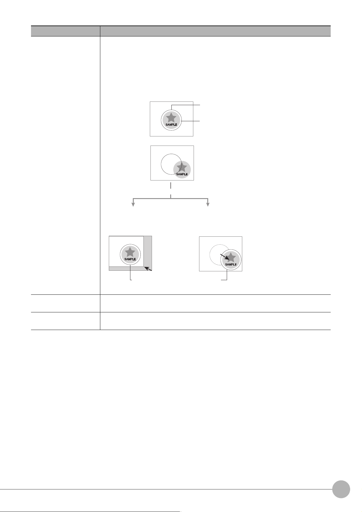
Ter m Definition
When position of object to be measured is deflected
When position deflection correction is set in advance:
Object to be measured
overflows Measurement area.
Reference position
Measurement area and objects to be measured
are correctly aligned.
Object to be measured
Measurement area
Measurement will be carried out
after measured object enters into Measurement area.
Measurement will be carried out after
moving the Measurement area for a
corresponding deflection.
Measurement will be carried out
after moving the image for a
corresponding deflection and
returning to the reference position.
Position compensation
When the locatio
between reference position and current position is calculated and measurement is performed
after correcting.
Please select processing items that are appropriate to the measurement object from
processing items that are related to position compensation.
n and direction of measured objects are not fixed, the positional deviation
Reference position
Model
The point that is always the reference. If the location of the registered model is different from
the reference position, the setting should be changed in [Ref. setting].
The image pattern that serves as the inspection target. Characteristics portions are extracted
from images of the object and registered as model registration.
Vision System FH/FZ5 Series
User’s Manual (Z365)
5
Page 8
Ter m Definition
−“1” is expresses with 2’s Complement (for 8 bits)
00000000 (= 0)
−
)
(In the case of 1, minus 1)
00000001 (= 1)
11111111 (=−1)
(
2's complement
Binary numbers are generally used to represent negative numbers.
Negative numbers are expressed by "Inverting all bits of a positive number and adding 1 to the
result".
(Example) "−1" is expressed as 2's complement
"−1" can be calculated by "0-1".
There are methods for simple calculation without performing this kind of computation.
For instance, "Negative number = inverting all bits of a positive number and then adding 1 to
the result".
00000001 (= 1)
Invert all bits
11111110
Plus 1
11111111 (=−1)
The first digit is used to judge whether the number is positive or negative.
• When 0: Positive number (or 0)
• When 1: Negative number
The advantage of two's complement numbers is that positive and negative numbers can be
used as is in calculations.
(Example) When −1+10=9
1
1111111 (= −1)
+)00001010 (= 10)
00001001
= 9)
6
Vision System FH/FZ5 Series
User’s Manual (Z365)
Page 9

Contents
Structure of FH/FZ5 Manuals ............................................................................................................... 1
Conventions Used in This Manual ........................................................................................................ 2
Definitions of Basic Terms .................................................................................................................... 3
Terms and Conditions Agreement ...................................................................................................... 13
Safety Precautions .............................................................................................................................. 15
Precautions for Safe Use .................................................................................................................... 17
Precautions for Correct Use ............................................................................................................... 20
Regulations and Standards ................................................................................................................ 23
1. Before Operation ..........................................................................................................................27
Overview .................................................................................................................................................. 28
Basic Mechanism for Measurements .................................................................................................. 28
Support for a Variety of Scenes and Measurement Lines .................................................................. 29
Flow of Application ................................................................................................................................... 31
Windows .................................................................................................................................................. 33
Types of Windows .............................................................................................................................. 33
Overview of Window Navigation ......................................................................................................... 34
Main Window (Layout 0): Adjustment Window (Default) .................................................................... 35
Main Window (Layout 1): Run Window (Default) ................................................................................ 41
Menu List ............................................................................................................................................ 42
Checking the System Configuration ......................................................................................................... 44
System Configuration ......................................................................................................................... 44
Functional Comparison between the FH-series and FZ5-series Controllers ...................................... 45
Saving Settings before Turning OFF the Power and Restarting .............................................................. 49
Restarting the Controller: [System Restart] ........................................................................................ 49
Turning OFF the LCD ......................................................................................................................... 50
Accuracy .................................................................................................................................................. 51
Initializing the Controller ........................................................................................................................... 52
Initializing the Controller: [System initialization] .................................................................................. 52
2. Setting Scenes (Measurement Flows) ........................................................................................53
What Is a Scene? ..................................................................................................................................... 54
Example of a Scene ............................................................................................................................ 55
What Is a Scene Group? .......................................................................................................................... 57
Creating a Scene ..................................................................................................................................... 58
Editing Processing Units in Scenes ......................................................................................................... 59
Displaying and Checking Processing Branches in a Scene .................................................................... 62
Changing the Scene or Scene Group ...................................................................................................... 66
Changing the Scene ........................................................................................................................... 66
Changing Scene Groups .................................................................................................................... 66
Editing Scenes ......................................................................................................................................... 68
Copying Scenes .................................................................................................................................. 68
Deleting Scenes .................................................................................................................................. 68
Renaming a Scene and Adding a Description .................................................................................... 69
Editing Scene Groups .............................................................................................................................. 70
Copying and Deleting Scene Groups ................................................................................................. 70
Changing the Scene Group Name ...................................................................................................... 71
Vision System FH/FZ5 Series
User’s Manual (Z365)
7
Page 10

3. Performing Test Measurement/Starting Operation ...................................................................73
Adjustment Windows and Run Windows ................................................................................................. 74
Main Window (Layout 0): Adjustment Window (Default) .................................................................... 74
Main Window (Layout 1): Run Window (Default) ................................................................................ 75
Main Window (Layout 1): Changing to the Run Window .................................................................... 75
Main Window (Layout 1): Changing to the Adjustment Window ......................................................... 75
Preparing the Controller and Cameras .................................................................................................... 76
Camera Setup ..................................................................................................................................... 76
Preparing a Controller ......................................................................................................................... 78
Adjusting the Camera ......................................................................................................................... 78
Executing Test Measurements ................................................................................................................ 79
Key Points for Adjustment ........................................................................................................................ 80
Stabilizing Measurements ................................................................................................................... 80
Shortening Processing Time ............................................................................................................... 81
Arranging Windows .................................................................................................................................. 83
Arranging Window Elements (Layout Modification) ............................................................................ 83
Setting the Behavior of Output Signals for Each Layout (Layout Settings) ........................................ 98
Changing Layout Numbers in the Main Window ................................................................................. 98
Troubleshooting .................................................................................................................................. 99
Arranging the Window Display ............................................................................................................... 100
Changing the Image Mode and Other Display Contents .................................................................. 100
Custom Dialogs ...................................................................................................................................... 103
Flow of Use ....................................................................................................................................... 103
Custom Dialog Tool .......................................................................................................................... 104
Launching Your Custom Dialog Box ................................................................................................. 115
Useful Functions for Operation .............................................................................................................. 116
Remeasuring Saved Images ............................................................................................................ 116
Improving Adjustment Efficiency ....................................................................................................... 117
Changing Judgement Conditions without Stopping Measurement ................................................... 118
Changing Regions as a Batch [Shift area] ........................................................................................ 119
Monitoring Measurement Value Trends ............................................................................................120
Logging Measurement Values and Measurement Images ............................................................... 120
Analyzing Logged Data ..................................................................................................................... 132
Clearing Measurement Results ........................................................................................................ 134
Clearing Saved Images .................................................................................................................... 134
Capturing Screen Images ................................................................................................................. 134
Checking the Memory Consumption and Percentage of Memory Used ........................................... 136
Using the Operation Log ................................................................................................................... 137
Operation Log Format ....................................................................................................................... 139
Saving Data to an External Device ................................................................................................... 140
8
Vision System FH/FZ5 Series
User’s Manual (Z365)
Page 11

4. Using Tools .................................................................................................................................143
Limiting user operations (Security settings) ........................................................................................... 144
Setting Accounts (Account List) ........................................................................................................ 144
Setting Layout Restrictions ............................................................................................................... 146
Setting User Group Operation Restrictions ......................................................................................147
Saving/Loading/Deleting the Security Settings ................................................................................. 149
Changing between user accounts .......................................................................................................... 155
Logging in ......................................................................................................................................... 155
Logging Out ...................................................................................................................................... 155
Saving Scene groups in external memory (Scene Group Saving Destination settings) ........................ 156
Analyzing inspection and measurement results (NG analyzer) ............................................................. 158
Layout of NG Analyzer Window ........................................................................................................ 159
Using Method of NG Analyzer .......................................................................................................... 160
Sharing data within the controller (User data tool) ................................................................................. 163
Setting Procedure for User Data ....................................................................................................... 163
Outputting a List of Scene Data Set Values (Settings download and upload tools) .............................. 165
Downloading Set Values ................................................................................................................... 165
About Downloaded CSV Files .......................................................................................................... 165
Uploading Set Values ....................................................................................................................... 167
Saving Image files to a RAMDisk, or External memory device (Image file save) .................................. 168
Managing images used for model registration and reference (Registered Image Manager) ................. 170
Registering Images ........................................................................................................................... 170
Loading an Image ............................................................................................................................. 171
Customizing communication commands (Communication command macro) ....................................... 172
Displaying a measurement flow as a flowchart while editing it (Flow viewer) ........................................ 173
Verifying calibration results (Calibration support tool) ............................................................................ 174
Updating the referenced position data for a unit in the measurement flow
(Update standard position tool) .............................................................................................................. 175
Increasing the number of scenes in a group to more than 128 scenes
(Conversion scene group data tool) ....................................................................................................... 177
Create a customized settings dialog box (Custom dialog tool) .............................................................. 180
Extending the functions in a measurement flow, or scene (Scene Control Macro Tool) ....................... 181
Backing up Sensor Controller setting data (Configuration copy) ........................................................... 182
Before backing up ............................................................................................................................. 182
Backing up Sensor Controller settings .............................................................................................. 184
Restoring settings with saved settings data ...................................................................................... 194
Troubleshooting ................................................................................................................................ 197
Changing settings for each line in Multi-line Random-trigger mode (Line Maintenance) ....................... 199
Before use of Line Maintenance ....................................................................................................... 199
Line Maintenance tool operations ..................................................................................................... 202
Operating with Functional Limitations ............................................................................................... 209
Troubleshooting ................................................................................................................................ 213
Remotely operating the controller (Remote Operation) ......................................................................... 214
Overview ........................................................................................................................................... 214
Operation Environment Condition ..................................................................................................... 215
How to Start ...................................................................................................................................... 217
Vision System FH/FZ5 Series
User’s Manual (Z365)
9
Page 12

5. Saving Data to the FH series/FZ5 series ..................................................................................221
Saving Data to the FH series/FZ5 series ............................................................................................... 222
About Saving Areas .......................................................................................................................... 222
External Drive Names ....................................................................................................................... 223
Using External Memory Devices (FH series/FZ5-1100 series only) ................................................. 224
Shared folder on a computer connected to the network ................................................................... 224
Saving Settings Data to the Flash Memory and Restarting ................................................................... 225
Saving Settings Data to the Controller RAMDisk or an External Memory Device ................................. 226
Saving Logged Images in the Controller Memory (RAM) to a RAMDisk or
an External Memory Device ................................................................................................................... 227
Copying or Moving Files between the Controller RAMDisk and an External Memory Device ............... 228
Loading Settings Data from the Controller RAMDisk or an External Memory Device to the
Sensor Controller ................................................................................................................................... 229
6. Changing the System Environment .........................................................................................231
Setting the Camera Conditions .............................................................................................................. 232
Checking the Camera Connections: [Camera Connection] .............................................................. 232
Setting the Trigger Delay: [Inter-camera setting] ..............................................................................232
Setting the SHTOUT Signal: [Output Signal Settings] ...................................................................... 235
Setting the Conditions That Are Related to Operation during Measurement ......................................... 237
Setting the Operation Mode ................................................................................................................... 238
Selection Guide for Operation mode ................................................................................................ 239
Double Speed Multi-input ................................................................................................................. 240
Multi-line Random-trigger Mode ....................................................................................................... 244
Non-stop Adjustment Mode .............................................................................................................. 250
Standard (Operation Mode) .............................................................................................................. 252
Parallel Processing ................................................................................................................................ 253
Parallel Processing Settings (Automatic Parallelization) .................................................................. 253
Parallel Processing Settings (Manual Parallelization) ...................................................................... 253
Specific Example of Parallel Processing .......................................................................................... 255
Restrictions ....................................................................................................................................... 256
Setting Procedures ........................................................................................................................... 259
Multi-trigger Imaging Processing Function ............................................................................................. 263
Settings for Multi-trigger Imaging ...................................................................................................... 264
Restrictions ....................................................................................................................................... 266
Setting Methods ................................................................................................................................ 267
About Multi-input function (Multi-trigger Imaging) .............................................................................271
Troubleshooting ................................................................................................................................ 276
Setting the Operating Environment of the System ................................................................................. 277
Selecting Language [Startup Settings] ............................................................................................. 277
Setting the Status at Startup [Startup Settings] ................................................................................ 278
Setting Communication [Startup Settings] ........................................................................................ 280
Setting Operation mode [Startup Settings] ....................................................................................... 284
Date-time setting [Other] ................................................................................................................... 285
Fan control setting [Other] ................................................................................................................ 285
STEP setting [Other] ......................................................................................................................... 286
Encoder trigger setting [Other] .......................................................................................................... 287
Network drive setting [Other] ............................................................................................................ 289
Error Setting [Other] .......................................................................................................................... 291
Checking System Information [System Information] ......................................................................... 293
10
Vision System FH/FZ5 Series
User’s Manual (Z365)
Page 13

7. Appendices ................................................................................................................................297
Alignment ............................................................................................................................................... 298
Overview ........................................................................................................................................... 298
Execution of Calibration .................................................................................................................... 301
Troubleshooting ................................................................................................................................ 308
Alignment .......................................................................................................................................... 309
Alignment Processing Items ............................................................................................................. 316
Error Messages and Troubleshooting .................................................................................................... 317
FAQ ........................................................................................................................................................ 323
During Start-up ................................................................................................................................. 323
During Operation .............................................................................................................................. 324
For Measurement ............................................................................................................................. 325
About Parallel Interface ................................................................................................................... 326
Serial Interface (RS-232C/422 Connection) ..................................................................................... 327
Camera with Lighting Controller ....................................................................................................... 327
Measurement Mechanism ...................................................................................................................... 328
Color Processing Mechanism .......................................................................................................... 328
Search Processing Mechanism ....................................................................................................... 329
Edge Detection Measurement .......................................................................................................... 332
Defect Detection Measurement ........................................................................................................ 335
Handling Coordinates ...................................................................................................................... 336
Basic Knowledge about Operations ....................................................................................................... 337
Inputting Values ............................................................................................................................... 337
Inputting Text ................................................................................................................................... 337
Selecting Files and Folders ............................................................................................................. 338
Available Operations in Select File Window ....................................................................................340
Using the Zoom Function .................................................................................................................. 341
Setting Figures ....................................................................................................................................... 342
Layout of Figure Setting Area .......................................................................................................... 342
Setting Methods ............................................................................................................................... 343
About OR Setting/NOT Setting ......................................................................................................... 349
Image file ............................................................................................................................................... 350
About Number of Logging Images ......................................................................................................... 352
About Limits on the Number of Image Input Processing Items Used .................................................... 355
About Max. Number of Loading Images during Multi-input .................................................................... 356
Character Code Table ............................................................................................................................ 357
About Memories Usable with FH series/FZ5 series ............................................................................... 358
Memory Usage Guidance For Processing Items ................................................................................... 359
Memory Display Image on PLC I/O ....................................................................................................... 364
Operation log input information list ........................................................................................................ 366
Manual Revision History ........................................................................................................................ 379
Vision System FH/FZ5 Series
User’s Manual (Z365)
11
Page 14

12
Vision System FH/FZ5 Series
User’s Manual (Z365)
Page 15

Terms and Conditions Agreement
Warranty, Limitations of Liability
Warranties
Exclusive Warranty
Omron’s exclusive warranty is that the Products will be free from defects in materials and workmanship for a
period of twelve months from the date of sale by Omron (or such other period expressed in writing by
Omron). Omron disclaims all other warranties, express or implied.
Limitations
OMRON MAKES NO WARRANTY OR REPRESENTATION, EXPRESS OR IMPLIED, ABOUT NONINFRINGEMENT, MERCHANTABILITY OR FITNESS FOR A PARTICULAR PURPOSE OF THE
PRODUCTS. BUYER ACKNOWLEDGES THAT IT ALONE HAS DETERMINED THAT THE PRODUCTS
WILL SUITABLY MEET THE REQUIREMENTS OF THEIR INTENDED USE.
Omron further disclaims all warranties and responsibility of any type for claims or expenses based on
infringement by the Products or otherwise of any intellectual property right.
Buyer Remedy
Omron’s sole obligation hereunder shall be, at Omron’s election, to (i) replace (in the form originally shipped
with Buyer responsible for labor charges for removal or replacement thereof) the non-complying Product, (ii)
repair the non-complying Product, or (iii) repay or credit Buyer an amount equal to the purchase price of the
non-complying Product; provided that in no event shall Omron be responsible for warranty, repair, indemnity
or any other claims or expenses regarding the Products unless Omron’s analysis confirms that the Products
were properly handled, stored, installed and maintained and not subject to contamination, abuse, misuse or
inappropriate modification. Return of any Products by Buyer must be approved in writing by Omron before
shipment. Omron Companies shall not be liable for the suitability or unsuitability or the results from the use of
Products in combination with any electrical or electronic components, circuits, system assemblies or any
other materials or substances or environments. Any advice, recommendations or information given orally or
in writing, are not to be construed as an amendment or addition to the above warranty.
See http://www.omron.com/global/ or contact your Omron representative for published information.
Limitation on Liability; Etc
OMRON COMPANIES SHALL NOT BE LIABLE FOR SPECIAL, INDIRECT, INCIDENTAL, OR
CONSEQUENTIAL DAMAGES, LOSS OF PROFITS OR PRODUCTION OR COMMERCIAL LOSS IN ANY
WAY CONNECTED WITH THE PRODUCTS, WHETHER SUCH CLAIM IS BASED IN CONTRACT,
WARRANTY, NEGLIGENCE OR STRICT LIABILITY.
Further, in no event shall liability of Omron Companies exceed the individual price of the Product on which
liability is asserted.
Vision System FH/FZ5 Series
User’s Manual (Z365)
13
Page 16

Application Considerations
Suitability of Use
Omron Companies shall not be responsible for conformity with any standards, codes or regulations which
apply to the combination of the Product in the Buyer’s application or use of the Product. At Buyer’s request,
Omron will provide applicable third party certification documents identifying ratings and limitations of use
which apply to the Product. This information by itself is not sufficient for a complete determination of the
suitability of the Product in combination with the end product, machine, system, or other application or use.
Buyer shall be solely responsible for determining appropriateness of the particular Product with respect to
Buyer’s application, product or system. Buyer shall take application responsibility in all cases.
NEVER USE THE PRODUCT FOR AN APPLICATION INVOLVING SERIOUS RISK TO LIFE OR
PROPERTY WITHOUT ENSURING THAT THE SYSTEM AS A WHOLE HAS BEEN DESIGNED TO
ADDRESS THE RISKS, AND THAT THE OMRON PRODUCT(S) IS PROPERLY RATED AND INSTALLED
FOR THE INTENDED USE WITHIN THE OVERALL EQUIPMENT OR SYSTEM.
Programmable Products
Omron Companies shall not be responsible for the user’s programming of a programmable Product, or any
consequence thereof.
Disclaimers
Performance Data
Data presented in Omron Company websites, catalogs and other materials is provided as a guide for the user
in determining suitability and does not constitute a warranty. It may represent the result of Omron’s test
conditions, and the user must correlate it to actual application requirements. Actual performance is subject to
the Omron’s Warranty and Limitations of Liability.
Change in Specifications
Product specifications and accessories may be changed at any time based on improvements and other
reasons. It is our practice to change part numbers when published ratings or features are changed, or when
significant construction changes are made. However, some specifications of the Product may be changed
without any notice. When in doubt, special part numbers may be assigned to fix or establish key
specifications for your application. Please consult with your Omron’s representative at any time to confirm
actual specifications of purchased Product.
Errors and Omissions
Information presented by Omron Companies has been checked and is believed to be accurate; however, no
responsibility is assumed for clerical, typographical or proofreading errors or omissions.
14
Vision System FH/FZ5 Series
User’s Manual (Z365)
Page 17
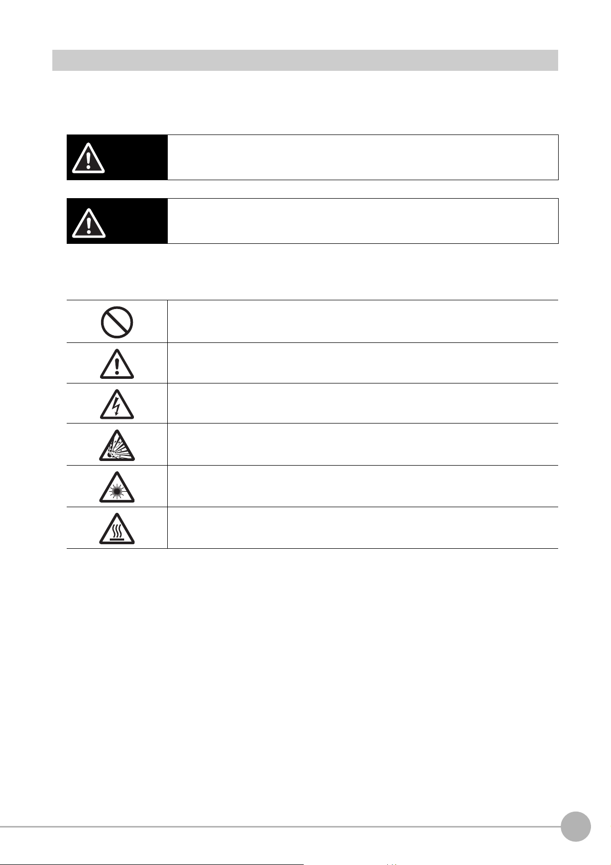
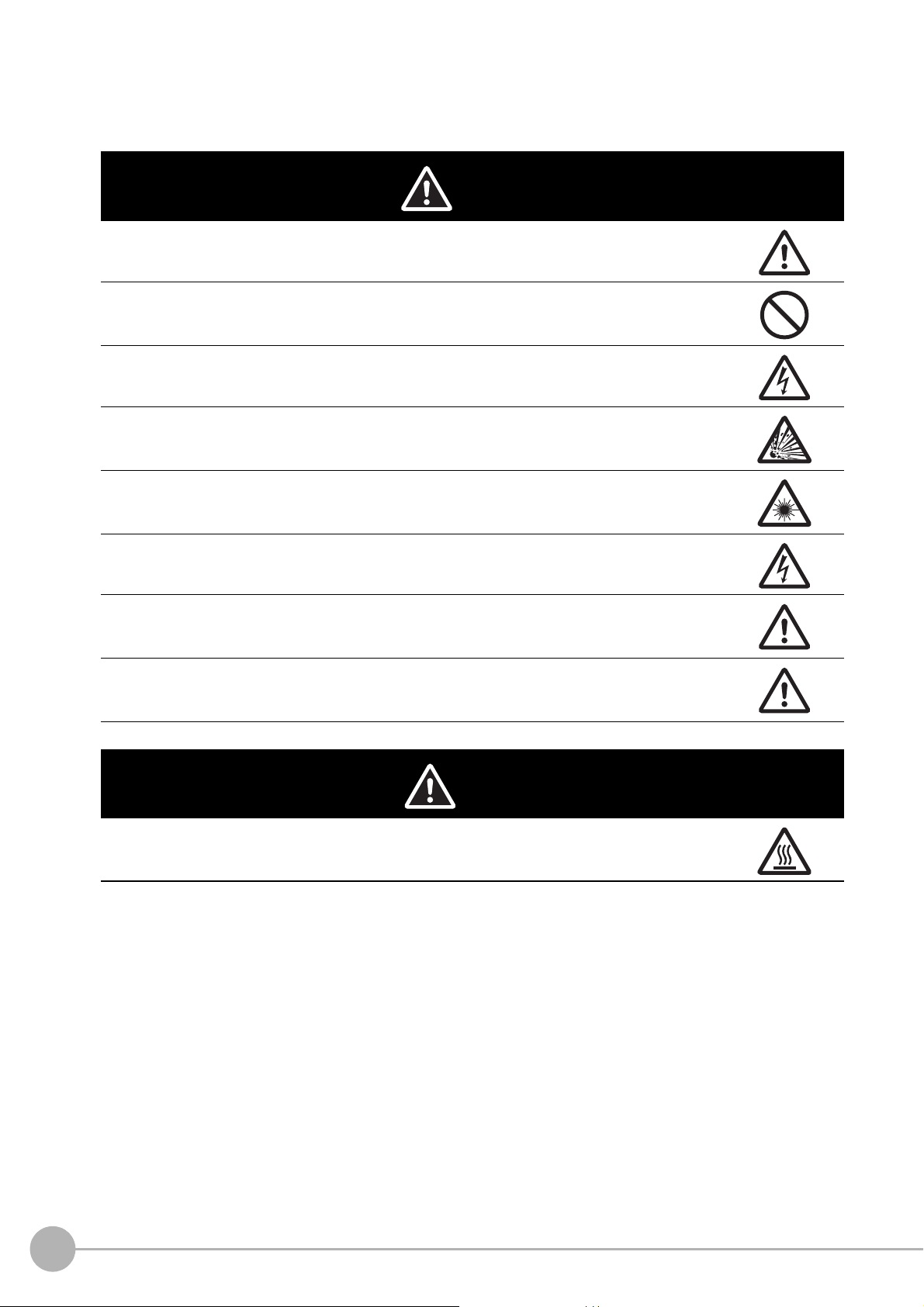
Safety Precautions
CAUTION
Symbols and the meanings for safety precautions described in this manual.
In order for the product to be used safely, the following indications are used in this book to draw your attention
to the cautions. The cautions with the indications describe the important contents for safety.
Indicates a potentially hazardous situation which, if not avoided, will result in minor or moderate
WARNING
injury, or may result in serious injury or death.
Additionally there may be significant property damage.
Indicates a potentially hazardous situation which, if not avoided, may result in minor or
moderate injury or in property damage.
Meanings of Alert Symbols
The following alert symbols are used in this manual.
General Prohibition
Indicates general prohibitions, including warnings, for which there is no specific symbol.
General Caution
Indicates general cautions, including warnings, for which there is no specific symbol.
Electrical Hazard
Indicates the possible danger of electric shock under specific conditions.
Explosion Hazard
Indicates the possible danger of explosion under specific conditions.
Laser Radiation Hazard
Indicates the possible danger of laser radiation or light.
High Temperature Caution
Indicates the possible danger of injury by high temperature under specific conditions.
Vision System FH/FZ5 Series
User’s Manual (Z365)
15
Page 18
Alert statements in this Manual
WARNING
The following alert statements apply to the products in this manual. Each alert statement also appears at the
locations needed in this manual to attract your attention.
This product must be used according to this manual or Instruction sheet.
Failure to observe this may result in impairment of functions and performance of the product.
This product is not designed or rated for ensuring safety of persons. Do not use it for such purposes.
Never connect the AC power supply with this product.
When the AC power supply is connected, it causes the electric shock and a fire.
A lithium battery is built into the Controller and may occasionally combust, explode, or burn if not
treated properly. Dispose of the Controller as industrial waste, and never disassemble, apply
pressure that would deform, heat to 100°C or higher, or incinerate the Controller.
Since camera that can be connected with this product emits a visible light that may have an adverse
effect on the eyes, do not stare directly into the light emitted from the LED. If a specular object is
used, take care not to allow reflected light enter your eyes.
Do not touch the terminals while the power supply is ON. Doing so may result in electrical shock.
Please take external safety measures so that the system as a whole should be on the safe side even
if a failure of a Sensor Controller or an error due to an external factor occurred. An abnormal
operation may result in serious accident.
Please take fail-safe measures on your side in preparation for an abnormal signal due to signal
conductor disconnection and/or momentary power interruption. An abnormal operation may result in
a serious accident.
CAUTION
Danger of burns. Do not touch the case while the LED is ON or just after power is turned OFF, since
it remains extremely hot.
16
Vision System FH/FZ5 Series
User’s Manual (Z365)
Page 19

Precautions for Safe Use
Condition of the fitness of OMRON products
• Please do not use this product to directly or indirectly use to detect the human body for the purpose of
ensuring the safety. In the same application, please use the safety sensor that is published on our sensor
catalog.
• Omron products are designed and manufactured as general-purpose products for use in general industrial
applications. They are not intended to be used in the following critical applications. If you are using Omron
products in the following applications, Omron shall not provide any warranty for such Omron products,
unless otherwise specifically agreed or unless the specific applications are intended by Omron.
(a) Applications with stringent safety requirements, including but not limited to nuclear power control
equipment, combustion equipment, aerospace equipment, railway equipment, elevator/lift equipment,
amusement park equipment, medical equipment, safety devices and other applications that could
cause danger/harm to people’s body and life.
(b) Applications that require high reliability, including but not limited to supply systems for gas, water and
electricity, etc., 24 hour continuous operating systems, financial settlement systems and other
applications that handle rights and property.
(c) Applications under severe condition or in severe environment, including but not limited to outdoor
equipment, equipment exposed to chemical contamination, equipment exposed to electromagnetic
interference and equipment exposed to vibration and shocks
(d) Applications under conditions and environment not described in specifications
*1 In addition to the applications listed from (a) to (d) above, Omron products (see definition) are not intended
for use in vehicles designed human transport (including two wheel vehicles). Please do NOT use Omron
products for vehicles designed human transport. Please contact the Omron sales staff for information on our
automotive line of products.
*2 The above is part of the Terms and Conditions Agreement. Please use carefully read the contents of the
guarantee and disclaimers described in our latest version of the catalog, data sheets and manuals.
Installation Environment
• Do not use the product in areas where flammable or explosive gases are present.
• Install the product so that air can flow freely through its cooling vents.
• Clean the ventilation holes and fan outlet regularly to prevent dust and particles from clogging them. If they
are blocked, heat is trapped inside, causing a malfunction.
• Do not install the product close to high-voltage devices and power devices in order to secure the safety of
operation and maintenance.
• Make sure to tighten all installation screws securely.
• When mounting the Sensor Controller using the DIN rail mounting bracket, make sure the screw is
tightened.
• Make sure to mount the product on DIN-rail securely.
Vision System FH/FZ5 Series
User’s Manual (Z365)
17
Page 20

Power Supply and Wiring
• Make sure to use the product with the power supply voltage specified by this manual or Instruction sheet.
• Do not connect AC power source to Sensor Controller. If connects AC power source, it might be a cause of
the failure.
• Use the wire of a suitable size (AWG 16 to 12) according to the current consumption.
• Use a DC power supply with safety measures against high-voltage spikes (safety extra low-voltage circuits
on the secondary side).
• Do the following confirmations again before turning on the power supply.
− Is the voltage and polarity of the power supply correct? (24 VDC)
− Is not the load of the output signal short-circuited?
− Is the load current of the output signal appropriate?
− Is not the mistake found in wiring?
− Is the voltage and polarity of the encoder power (ENC0_VDD/GND ENC1_VDD/GND) supply? (5 VDC)
• The recommended power supply is the S8VS-24 (manufactured by OMRON) or S8VK-G-24
(manufactured by OMRON).
Ground
• Make sure the power supply circuit of the FH Sensor Controller is insulated from the internal circuit.
Refer to this manual or Instruction sheet.
• When the connected camera to Sensor Control comes packaged with a base, make sure to mount with the
base. Since the enclosure of the camera main body made of metals is short-circuited with the internal
circuit, the internal circuit might be short-circuited with FG if no base is used, so that failures or
malfunctions may be caused.
Perform Class D grounding (with a grounding resistance of 100 Ω or less).
Keep the ground line as short as possible by setting the grounding point as close as possible.
Ground the FH Sensor Controller independently. If sharing the ground line with other devices or
connecting it with a building beam, the Sensor Controller might be adversely effected.
• Check wiring again before turning on the FH Sensor Controller.
• Do not ground the plus (+) terminal when the FH series Sensor Controller is connected to the FH-SC12/
FH-SM12. Doing so may cause a short circuit of the internal circuit, resulting in a malfunction.
The internal circuit is possible to be given damage, it can be cause the failure.
− FH-1000 series
− FH-3000 series
− FH-L series
• Do not ground the plus (+) terminal of the 24VDC power source when the FH series Sensor Controller is
connected to the FH-MT12 with a USB cable. Doing so may cause a short circuit of the internal circuit,
resulting in a malfunction.
− FH-1000 series
− FH-3000 series
− FH-L series
18
Vision System FH/FZ5 Series
User’s Manual (Z365)
Page 21

Other
• Use only the camera and cables designed specifically for the product. Use of other products may result in
malfunction or damage of the product.
• Always turn OFF the power of the Sensor Controller and peripheral devices before connecting or
disconnecting a camera or cable. Connecting the cable with power supplied may result in damage of the
camera or peripheral devices.
• For the cable that is flexed repeatedly, use the robotic cable type (Bend resistant camera cable) to prevent
damages.
• Do not apply torsion stress to the cable. It may damage the cable.
• Secure the minimum bending radius of the cable. Otherwise the cable may be damaged.
• Do not attempt to dismantle, repair, or modify the product.
• Should you notice any abnormalities, immediately stop use, turn OFF the power supply, and contact your
OMRON representative.
• While the power is ON or immediately after the power is turned OFF, the Sensor Controller and camera
case are still hot. Do not touch the case.
• When disposing of the product, treat it as an industrial waste.
• Do not drop the product nor apply excessive vibration or shock to the product. Doing so may cause
malfunction or burning.
• This product is heavy. Be careful not to drop it while handling.
• A lithium battery is incorporated, so a severe injury may rarely occur due to ignition or explosion.
• Be sure to take fail-safe measures externally when controlling stages and robots by using the
measurement results of the Sensor Controller (axis movement output by calibration and alignment
measurement).
Vision System FH/FZ5 Series
User’s Manual (Z365)
19
Page 22

Precautions for Correct Use
Installation and Storage Sites for FH-1000 series/FH-3000 series/FZ5-1100 series/
FZ5-600 series/FZ5-L series
Install and store the product in a location that meets the following conditions:
• Surrounding temperature of 0 to +50°C
• No rapid changes in temperature (place where dew does not form)
• Relative humidity of between 35 to 85%
• No presence of corrosive or flammable gases
• Place free of dust, salts and iron particles
• Place free of vibration and shock
• Place out of direct sunlight
• Place where it will not come into contact with water, oils or chemicals
Installation and Storage Sites for FH-L series
Install and store the product in a location that meets the following conditions:
• Surrounding temperature of 0 to +55°C (-25 to +70°C in storage)
• No rapid changes in temperature (place where dew does not form)
• Relative humidity of between 10 to 90%
• No presence of corrosive or flammable gases
• Place free of dust, salts and iron particles
• Place free of vibration and shock
• Place out of direct sunlight
• Place where it will not come into contact with water, oils or chemicals
• Place not affected by strong electro-magnetic waves
• Place not near to high-voltage, or high-power equipment
Orientation of Product
• For good heat dissipation, install the product only in the position written this manual or Instruction sheet so
as not to block the ventilation holes.
Ambient Temperature
• For good heat dissipation, keep the distance written this manual or Instruction sheet.
• Do not install the product immediately above significant heat sources, such as heaters, transformers, or
large-capacity resistors.
• Do not let the ambient temperature exceed an operating temperature range.
• Provide a forced-air fan cooling or air conditioning if the ambient temperature is near the upper range of
operating temperature range so that the ambient temperature never exceeds the upper range of operating
temperature range.
Noise Resistance
• Do not install the product in a cabinet containing high-voltage equipment.
• Do not install the Sensor Controller within 200 mm of power cables.
20
Vision System FH/FZ5 Series
User’s Manual (Z365)
Page 23

Component Installation and Handling
• Touching Signal Lines
To prevent damage from static electricity, use a wrist strap or another device for preventing electrostatic
discharges when touching terminals or signal lines in connectors.
• Handling a USB Memory/SD memory card.
Refer to Using External Memory Device in the Vision System FH/FZ5 series User’s Manual (Cat. No.
W365).
• Do not insert an SD memory card in the reverse orientation, at an angle, or in a twisting manner.
Before removing a USB memory device or SD memory card, make sure that data is not being read or
written to them.
For a USB memory device, the memory device's LED flashes while data is being read or written. Make
sure that the LED stops flashing before removing the memory device.
For an SD memory card, the SD BUSY LED of Sensor Controller flashes while data is being read or
written. Make sure that the LED stops flashing before removing the card.
• Turning OFF the Power
When a message is displayed indicating that a task is in progress, do not turn OFF the power. Doing so
causes the data in the memory to be corrupted, resulting in the product not operating properly upon the
next start-up.
When turns OFF, conform the followings proceedings have completed. and then operate again.
− When saves using Sensor Controller:
Confirm the save processing is completed and next operation is possible.
− When saves using communication command:
Intended command is completed. BUSY signal is turned OFF
• Setting of Power Source
The power source need to be supplied from DC power source apparatus which is taken a save ultra-low
voltage circuit: to protect high voltage.
Maintenance
• Turn OFF the power and ensure the safety before maintenance.
• Clean the lens with a lens-cleaning cloth or air brush.
• Lightly wipe off dirt with a soft cloth.
• Dirt on the image element must be removed using an air brush.
• Do not use thinners or benzene.
• To ensure safe access for operation and maintenance, separate the Sensor Controller as much as
possible from high-voltage equipment and power machinery.
Communication with High-order Device
• After confirming that this product is started up, communicate with the high-order device. When this product
has started up, an indefinite signal may be output from the high-order interface. To avoid this problem,
clear the receiving buffer of your device at initial operations.
Fail-Safe Measures
• When controlling stages and robots using the measurement results from the Sensor Controller (axis
movement output based on calibration and alignment measurement), always take fail-safe measures
within the stage and robot systems, such as checking whether the data obtained from the measurement
results is within the range of movement of the stages and robots.
• On a FH Sensor Controller side, supplementary use operations and branches of the Sensor Controller to
configure a check flow such as “data should not be externally provide if the data is in a range from
-XXXXX to XXXXX” based on the stage/robots range of movement.
Vision System FH/FZ5 Series
User’s Manual (Z365)
21
Page 24

Connecting the Sensor Controller and Monitor with a Switcher and Splitter
• Do not use devices that make the Sensor Controller recognize the monitor again when switching operation
is performed. Re-recognition process in switching operation has an effect such as a delay in measurement
time.
22
Vision System FH/FZ5 Series
User’s Manual (Z365)
Page 25
Regulations and Standards
All Series
Using Product Outside Japan
This regulation applies to FH/FZ5 sensor controller and peripheral devices.
If you export (or provide a non-resident with) this product or a part of this product that falls under the category
of goods (or technologies) specified by the Foreign Exchange and Foreign Trade Control Law as those which
require permission or approval for export, you must obtain permission or approval or service transaction
permission) pursuant to the law.
U.S. California Notice:
This product contains a lithium battery for which the following notice applies: Perchlorate Material - special
handling may apply.
See www.dtsc.ca.gov/hazardouswaste/perchlorate
Conformance to KC Standards
This regulation applies to FH/FZ5 sensor controller and peripheral devices.
Observe the following precaution if you use this product in Korea.
• Class A Device (Broadcasting Communications Device for Office Use)
This device obtained EMC registration for office use (Class A), and it is intended to be used in places other
than homes. Sellers and/or users need to take note of this.
Vision System FH/FZ5 Series
User’s Manual (Z365)
23
Page 26

FH-1000/FH-3000 series
Conformance to EC/EU Directives
This regulation applies to FH-1000/FH-5000 series Sensor Controller and peripheral devices.
The FH-1000/FH-5000 series Sensor Controller is compliant with the standards below:
• EC Directive 2004/108/EC (Until April 19 2016) / EU Directive 2014/30/EU (After April 20 2016)
EN61326-1
Electromagnetic environment: Industrial electromagnetic environment (EN/IEC 61326-1 Table 2)
• Also, the following condition is applied to the immunity test of this product.
− If the level of disturbance of the video is such that characters on the monitor are readable, the test is a
pass.
• This product complies with EC/EU Directives. EMC-related performance of the OMRON devices that
comply with EC/EU Directives will vary depending on the configuration, wiring, and other conditions of the
equipment or control panel on which the OMRON devices are installed.
• The customer must, therefore, perform the final check to confirm that devices and the overall machine
conform to EMC standards.
• If there is a need to respond to the EC / EU directive, please use by an analog RGB output.
Conformance to UL Standards
This regulation applies to FH-1000 and FH-3000 series Sensor Controller and peripheral devices.
This product complies with UL Standards.
• UL508
FH-L series
Conformance to EC/EU Directives
This regulation applies to FH-L series Sensor Controller and peripheral devices.
The FH-L series Sensor Controller is compliant with the standards below:
• EC Directive 2004/108/EC (Until April 19 2016) / EU Directive 2014/30/EU (After April 20 2016)
EN61326-1
Electromagnetic environment: Industrial electromagnetic environment (EN/IEC 61326-1 Table 2)
• Also, the following condition is applied to the immunity test of this product.
− If the level of disturbance of the video is such that characters on the monitor are readable, the test is a
pass.
• This product complies with EC/EU Directives. EMC-related performance of the OMRON devices that
comply with EC/EU Directives will vary depending on the configuration, wiring, and other conditions of the
equipment or control panel on which the OMRON devices are installed.
• The customer must, therefore, perform the final check to confirm that devices and the overall machine
conform to EMC standards.
• If there is a need to respond to the EC / EU directive, please use by an analog RGB output.
Conformance to UL Standards
This regulation applies to FH-L series Sensor Controller and peripheral devices.
This product complies with CSA Standards.
• UL 61010-2-201
24
Vision System FH/FZ5 Series
User’s Manual (Z365)
Page 27

FZ5/FZ5-L series
Conformance to EC/EU Directives
This regulation applies to FZ5/FZ5-L series Sensor Controller and peripheral devices.
The FZ5/FZ5-L series Sensor Controller is compliant with the standards below:
• EC Directive 2004/108/EC (Until April 19 2016) / EU Directive 2014/30/EU (After April 20 2016)
EN61326-1
• Electromagnetic environment: Industrial electromagnetic environment (EN/IEC 61326-1 Table 2)
• Also, the following condition is applied to the immunity test of this product.
− If the level of disturbance of the video is such that characters on the monitor are readable, the test is a
pass.
• This product complies with EC/EU Directives. EMC-related performance of the OMRON devices that
comply with EC/EU Directives will vary depending on the configuration, wiring, and other conditions of the
equipment or control panel on which the OMRON devices are installed.
• The customer must, therefore, perform the final check to confirm that devices and the overall machine
conform to EMC standards.
Conformance to CSA Standards
This regulation applies to FZ5/FZ5-L Sensor Controller and peripheral devices.
This product complies with CSA Standards.
• CSA C22.2 No.61010-1
Vision System FH/FZ5 Series
User’s Manual (Z365)
25
Page 28

MEMO
26
Vision System FH/FZ5 Series
User’s Manual (Z365)
Page 29

Before Operation
This section describes the basic flow and preparations that are necessary to start
operation.
Overview............................................................................. 28
Flow of Application ........................................................... 31
Windows............................................................................. 33
Checking the System Configuration................................ 44
Saving Settings before Turning OFF the Power and
Restarting........................................................................... 49
Accuracy ............................................................................ 51
Initializing the Controller .................................................. 52
1
Before Operation
Page 30
Overview
Note
PLC or other external device
Image Input
Defect
Search
Measurement flow
FH/FZ5
Output Unit
Camera
Measurement
trigger
The measurement flow is executed basically in
order of the unit numbers.
Measurement
results are
output.
Measurement
processing of
the input image
Image input
from the
Camera
• Judgement
result
• Measured
values
Basic Mechanism for Measurements
An FH/FZ5-series Sensor Controller uses pre-built packages that contain all the processing tasks (for image
input, measurement processing, displays, outputs, etc.) that are required for vision inspections.
You arrange these packaged processes in order of execution of the vision inspection.
An FH/FZ5-series Controller executes vision inspections according to user-created flows.
In the FH/FZ5, a flow that contains packaged processes that are arranged in order of execution of processing items and
image processing is called a measurement flow.
Processing items and measurement flows can have more than one setting. You can switch the setting based on the scene
to inspect. (Reference: Setting Scenes (Measurement Flows) (p.53))
Concept of Measurement Processing
When the FH/FZ5 receives a measurement trigger from the PLC or other external device, the image input
from a Camera, measurement processing, and output of measurement results (e.g., OK/NG judgement
results) are executed in the order that those processing items are registered in the measurement flow.
• In the measurement flow, you can change the processing to execute based on the inspection results or input conditions of
the vision inspection.
• You can use macro processing to execute pre-packaged processing items and functions in the FH/FZ5 to create original
programs. This allows you to create original measurement processes, display processing, input and output processing,
and settings dialog boxes that are custom-tailored to your application.
28
Overview
Vision System FH/FZ5 Series
User’s Manual (Z365)
Page 31

Support for a Variety of Scenes and Measurement Lines
Image Input
Defect
Search
Measurement flow
Output Unit
Scene groups (0 to 31)
Scene group 0
Scenes (0 to 127)
Scene 0
You can have more than one setting for a measurement flow, depending on the inspections. This is called a
scene and you can set up to 128 scenes. (Reference: What Is a Scene? (p.54))
You can also combine more than one scene into a scene group. Management of scenes by scene groups
increases the number of scenes that you can handle. (Reference: What Is a Scene Group? (p.57))
1
Before Operation
Vision System FH/FZ5 Series
User’s Manual (Z365)
Overview
29
Page 32

If you have more than one measurement line, the FH allows you to selectively execute up to eight measurement
Camera
......
......
You can
create
settings for
up to 8 lines.
You can connect a
total of eight
Cameras for all
lines combined.
FH Controller
Line 0
Line 1
Line 7
Scene groups (0 to 31)
Scene groups (0 to 31)
Scene groups (0 to 31)
Scenes (0 to 127)
Scenes (0 to 127)
Scenes (0 to 127)
lines. This allows you to maintain settings for the scenes and scene groups for every line from 0 to 7.
You can connect up to eight Cameras to the FH, (four for the FZ5), and selectively control each Camera.
(Reference: Multi-line Random-trigger Mode (p.244))
30
Overview
Vision System FH/FZ5 Series
User’s Manual (Z365)
Page 33

Flow of Application
The following table shows the flow for using the FH/FZ5.
Procedure Description Reference
Vision System FH/FZ5 Series
Hardware Setup Manual (Cat.
No. Z366)
FH Instruction Manual
FZ5 Instruction Manual
Vision System FH/FZ5 Series
Hardware Setup Manual (Cat.
No. Z366)
FH Instruction Manual
FZ5 Instruction Manual
Reference: Selecting
Language [Startup Settings]
(p.277)
Reference: Adjustment
Windows and Run Windows
(p.74)
Reference: Preparing the
Controller and Cameras
(p.76)
Reference: Changing the
System Environment (p.231)
Reference: Saving
Settings before Turning OFF
the Power and Restarting
(p.49)
Reference: Loading
Settings Data from the
Controller RAMDisk or an
External Memory Device to
the Sensor Controller (p.229)
Reference: Changing the
System Environment (p.231)
Reference: Saving
Settings before Turning OFF
the Power and Restarting
(p.49)
Reference: Loading
Settings Data from the
Controller RAMDisk or an
External Memory Device to
the Sensor Controller (p.229)
Preparations
Installation and Wiring
↓
Turning ON Power
↓
Language Selection in Dialog Box (only when the Sensor Controller is
started for the first time)
↓
Main Window (Layout 0) Display
↓
Camera Adjustments (Display the settings dialog box for a Camera Image
Input processing item.)
↓
Select [Tool] − [System settings], and then under [Startup setting], set the
settings for [Basic], [Communication], and [Operation mode].
↓
Click the [Data save] button, and then select [Function] − [System restart].
↓
Select [Tool] − [System settings], and then set the settings for [Camera],
[Communication] and [Other].
↓
Click the [Data save] button, and then select [Function] − [System restart].
1
Before Operation
Vision System FH/FZ5 Series
User’s Manual (Z365)
Flow of Application
31
Page 34

Procedure Description Reference
↓
Scene Editing
↓
Testing
↓
Measuring
(Operation)
↓
Management and
Analysis
In the Main Window (layout 0), edit the measurement flow.
• Register processing items.
• Set the properties for each processing item.
↓
Click the [Data save] button.
Execute test measurements.
(In the Main Window (layout 0), click the [Measure] button.)
↓
Adjust the parameters for each processing item.
↓
Click the [Data save] button.
In the Main Window (layout 0), click the [Switch layout] button, and then
select [Main Window (Layout 1)].
↓
In the Main Window (layout 1), check the communications with the PLC.
↓
In the Main Window (layout 1), execute commands from the PLC, such as
measurement trigger commands.
Save and analyze measurement data and images.
Reference: Setting Scenes
(Measurement Flows) (p.53)
Reference: Saving
Settings before Turning OFF
the Power and Restarting
(p.49)
Reference: Loading
Settings Data from the
Controller RAMDisk or an
External Memory Device to
the Sensor Controller (p.229)
Reference: Performing
Test Measurement/Starting
Operation (p.73)
Vision System FH/FZ5 Series
Processing Item Function
Reference Manual (Cat. No.
Z341)
Reference: Saving
Settings before Turning OFF
the Power and Restarting
(p.49)
Reference: Loading
Settings Data from the
Controller RAMDisk or an
External Memory Device to
the Sensor Controller (p.229)
Reference: Performing
Test Measurement/Starting
Operation (p.73)
Vision System FH/FZ5 Series
User's Manual for
Communications
Settings (Cat. No. Z342)
Vision System FH/FZ5 Series
User's Manual for
Communications
Settings (Cat. No. Z342)
Reference: Useful
Functions for Operation
(p.116)
Reference: Using Tools
(p.143)
32
Flow of Application
Vision System FH/FZ5 Series
User’s Manual (Z365)
Page 35

Windows
Note
IMPORTANT
Types of Windows
There are 9 windows (with layout numbers 0 to 8) that you can use to set and operate an FH/FZ5.
Layout Application
Layout 0
Layout 1
Layout 2 to layout 8
If necessary, you can change layout 0 and layout 1 from the default adjustment window and run window and use them for
other purposes.
If the operation mode is set to Multi-line Random-trigger Mode, you must create a layout for each line. (Reference: Multiline Random-trigger Mode (p.244))
Layout 0 is the adjustment window by default.
(Reference: Main Window (Layout 0): Adjustment Window (Default) (p.74))
Layout 1 is a run window by default.
(Reference: Main Window (Layout 1): Run Window (Default) (p.75))
Layouts 2 to 8 are for user-defined purposes and are created as they are needed. (Reference:
Arranging the Window Display (p.100))
For example, if more than one line is being controlled, you can set and use a separate window
for each line.
(Reference: Multi-line Random-trigger Mode (p.244))
1
Before Operation
Vision System FH/FZ5 Series
User’s Manual (Z365)
Windows
33
Page 36

Overview of Window Navigation
y
(Reference: Edit
Flow Window (p.38))
(Reference:
Properties Dialog Box (p.40))
Startup
Startup Layout*
Layout
Layout 0
(default:
adjustment window)
Flow Editing
Edit Flow Window
* Select as follows: [System settings] − [Startup setting] − [Basic] tab − [Startup layout].
Default: [La
out 0] (both local and remote)
switching
Layout 1
(default: run window)
Unit Setting Mode
Properties Dialog Box
Layout
switching
(You can create these
Layouts 2 to 7
windows in Layout
Modification Mode)
34
Windows
Vision System FH/FZ5 Series
User’s Manual (Z365)
Page 37

Main Window (Layout 0): Adjustment Window (Default)
Note
3. Toolbox Pane
This button displays the edit flow window.
4. Measurement Pane
7. Flow Display Pane
6. Detail Result Pane
The Properties
Tab Page is
displayed.
2. Information
Pane
1. Judgement
Pane
5. Image
Pane
(Reference: p.38)
(Reference:
p.40)
You use this window to set up a measurement process and perform test measurements to confirm whether the
measurements are processed as intended.
Based on the results of the test measurement, move to the property settings for each processing unit and make
adjustments.
When the Main Window (layout 0) is being displayed, measurement results are not output and the RUN signal
remains OFF. (Layout modification can be used to change the layout.)
You can manually execute or stop test measurements.
If the measurement results are stable, switch to the Main Window (layout 1) and perform measurements.
Use the following procedure to change to Main Window (layout 1).
Select [Switch layout] from the [Function] menu (default layout).
Names of the Parts of the Main Window (Layout 0): Adjustment Window (Default)
1
Before Operation
1. Judgement Pane
• Overall Judgement Result
The overall judgment (OK/NG) for the scene is displayed.
This is the overall judgement result for the entire scene. If any processing unit that is reflected in the
overall judgement returns NG, the overall result is NG.
*1: The judgement results for individual processing units are displayed in the Detail Result Pane.
Vision System FH/FZ5 Series
User’s Manual (Z365)
Windows
35
Page 38

2. Information Pane
• Layout:
The number of the currently display layout is displayed.
• Processing time:
The time required for the measurement process is displayed.
• Scene group name and scene name:
The scene group number and the scene number of the currently displayed scene are displayed.
3. Toolbox Pane
• [Edit flow]:
This button starts the edit flow window that is used to edit flows. (Reference: Edit Flow Window (p.38))
• [Data save]:
This saves settings data to the flash memory in the Controller. If you make any changes to the settings,
make sure to click this button to save the settings.
• [Switch scene]:
This button switches between scene groups and scenes:
• [Switch layout]:
This button switches the layout number.
4. Measurement Pane
• Camera image meas.:
This button performs a test measurement on the Camera image.
• Image file meas.:
This button re-measures saved images.
• Output:
Select this option to output the measurement results of test measurements that are performed in the
Adjustment Window. Do not select this option if you need to perform test measurements on the Sensor
Controller but do not need to output the results externally.
This setting menu is used for temporary setting changes while the Main Window is displayed. When the
scene or layout is changed, the "Output" setting in the Layout setup is applied without saving the "Output"
setting in the Measurement Pane. Use as appropriate for your application.
(Reference: Setting the Behavior of Output Signals for Each Layout (Layout Settings) (p.98))
• Continuous meas.:
Select this option to continuously perform test measurements in the Adjustment Window.
Select the [Continuous meas.] option and click [Measure] to repeatedly execute measurements.
36
Windows
Vision System FH/FZ5 Series
User’s Manual (Z365)
Page 39

5. Image Pane
Click on the left side of the processing unit name.
This pane shows the measured image.
It also displays the selected processing unit name or the [Define displayed unit].
• Click on the left side of the processing unit name to display the Properties Dialog Box for the Image
Pane.
1
Before Operation
On this dialog box, you can change the image mode and other contents that are displayed in the Image
Display Pane.
(Reference: Changing the Image Mode and Other Display Contents (p.100))
• Click the upper corner of the Image Display Pane to display the [Add Image Window] button and
[Alignment] button. This allows you to display more than one pane side by side.
(Reference: Arranging Window Elements (Layout Modification) (p.83))
6. Detail Result Pane
This pane displays the results of test measurements.
The floating point number is rounded off to four digits after decimal point.
The floating point numbers that are saved as data will not be rounded off.
7. Flow Display Pane
This pane displays the contents of the measurement process (the processing that is set in the
measurement flow).
Click the icon of any processing item to display the Properties Dialog Box to set processing item
parameters and other settings. (Reference: Properties Dialog Box (p.40))
You can use the following buttons to move to the next processing unit with an NG judgement result.
[1st NG unit]: Moves to the first processing unit with an NG judgement.
[Next NG unit]: Moves to the next processing unit with an NG judgement.
[ ] "Property setting" button: Displays the property setting window of selected processing unit.
Vision System FH/FZ5 Series
User’s Manual (Z365)
Windows
37
Page 40

Edit Flow Window
3. End marker
1. Unit List 4. Flow editing buttons
2. Property
setting buttons
6. Processing
items tree
5. Display
options
The edit flow window is used to create measurement flows. You use the edit buttons to arrange processing units
in a scene, or to add or delete units.
The right side shows the processing items that can be used as parts in the measurement flow. The left side
shows the scene as the measurement flow.
When a measurement trigger is input, processing is executed in sequence starting from the top of the
measurement flow.
Click the button for any processing item that is set in the measurement flow, or click the [Set] button to open the
Properties Dialog Box.
1. Unit List
The processing units included in the flow are displayed in a list.
You can create a flow for a scene by adding processing items to the unit list.
2. Property Setting Buttons
The Properties Dialog Box is displayed and allows you to make detailed settings.
3. End Marker
This marker indicates the end of the flow.
4. Flow Editing Buttons
You can use these buttons to change the order of processing units within the scene or to delete processing
units.
(Reference: Editing Processing Units in Scenes (p.59))
5. Display Options
• Enlarge flow
When this option is selected, the Unit list flow (1) is displayed with large icons.
• Enlarge item tree
When this option is selected, the processing item tree (6) is displayed with large icons.
• Ref. other Scene's flow
When this option is selected, other scene flows within the same scene group can be referred to.
38
Windows
Vision System FH/FZ5 Series
User’s Manual (Z365)
Page 41

6. Processing Items Tree
This area allows you to select an item to add to the flow. The items are displayed in tree format that is
organized by type.
Click the [+] button for each item to display the lower level items. Click the [-] button for each item to hide the
lower level items.
When [Ref.other Scene’s flow] is selected, the scene select box and other scene flows are displayed.
1
Before Operation
Vision System FH/FZ5 Series
User’s Manual (Z365)
Windows
39
Page 42

Properties Dialog Box
Note
This dialog box is used to set measurement parameters, judgement conditions, and other conditions for
processing items that are registered as processing units in the measurement flow.
3. Image Display Area
1. Item Tab Area
2. Detail Area
4. Zoom Browser Area
1. Item Tab Area
The parameters for the processing unit that is currently being set are displayed. Settings are performed
starting with the item on the left.
2. Detail Area
This area is used to set detail items.
3. Image Display Area
This area shows Camera images, figures, positions, and other graphic information.
4. Zoom Browser Area
Use this area to zoom in and out from the displayed image.
You can use the zoom browser function using your mouse wheel on the image display area where is applied to the property
setting window of FH series/ FZ5-1100 series.
40
Windows
Vision System FH/FZ5 Series
User’s Manual (Z365)
Page 43

Main Window (Layout 1): Run Window (Default)
Note
Judgement
Pane
Information Pane
Flow Display
Pane
Detail Result
Pane
Image
Pane
Displays the
Properties
Window.
(p.91)
(p.89)
(p.89)
(p.92)
(p.92)
(p.40)
This window is used to perform actual measurements. The measurement results are output through the
communications interfaces.
If the Controller is ready to perform measurements, the RUN signal turns ON.
When this window is displayed, the FH/FZ5 is ready to perform measurements.
If a measurement trigger is input from an external device, the FH/FZ5 begins execution of measurement
processing according to the contents and sequence that is set in the measurement flow.
Use the following procedure to change to Main Window (layout 0).
Select [Switch layout] from the [Function] menu (default layout).
Names of the Parts of the Main Window (Layout 1): Run Window (Default)
The functions of each display window are the same as for the Main Window (layout 0).
The Toolbox Pane and Measurement Pane that are displayed on the Main Window (layout 0) are not
displayed.
(Layout modification can be used to change the layout.)
1
Before Operation
Vision System FH/FZ5 Series
User’s Manual (Z365)
Windows
41
Page 44

Menu List
The menu for the Main Window is described below.
Main menu
File End
Measure
Scene switch
Scene
maintenance
Edit flow Used to edit measurement flows.
Switch layout Changes the layout number to display.
Clear
measurement
Clear logging
image
Screen capture Captures the screen that is being displayed.
Function
Saving last
logging image
Data save
Save to file
Load from file Loads a settings file.
System
initialization
System restart Restarts the Controller.
Transfer data
Non-stop data
Function
transfer
Operation log
System
information
Command Description Reference
Exits the FH/FZ5 System.
After you exit the system, restart the system or
turn OFF the power supply.
Executes a test measurement (single or
continuous measurement), or a re-measurement.
This button switches between scene groups and
scenes:
Used to copy, delete, and rename scenes and
scene groups.
Clears the measurement data.
Clears the images that are logged in the
Controller.
Logs the most recent input images that are being
displayed.
Saves settings data to the flash memory in the
FH/FZ5.
Saves the settings data, logged images, and
logged data to a file. It also copies files between
memory devices.
Restores the Controller to the default settings.
Transfers (copies) the settings for line 0 to line 1,
and then changes to the Non-stop Adjustment
Mode.
Transfers (copies) the settings for line 1 to line 0
in Non-stop Adjustment Mode without affecting
measurements.
Saves the operation log of the Controller to a
special file.
Displays the Controller’s model and software
version.
---
Reference: Executing Test
Measurements (p.79)
Reference: Remeasuring Saved Images
(p.116)
Reference: Changing the Scene or
Scene Group (p.66)
Reference: Editing Scenes (p.68)
Reference: Editing Scene Groups (p.70)
Reference: Editing Processing Units in
Scenes (p.59)
Reference: Arranging Window Elements
(Layout Modification) (p.83)
Reference: Clearing Measurement
Results (p.134)
Reference: Clearing Saved Images
(p.134)
Reference: Capturing Screen Images
(p.134)
Reference: Logging Measurement
Values and Measurement Images (p.120)
Reference: Saving Settings before
Turning OFF the Power and Restarting
(p.49)
Reference: Saving Data to the FH
series/FZ5 series (p.221)
Reference: Saving Data to the FH
series/FZ5 series (p.221)
Reference: Initializing the Controller
(p.52)
Reference: Saving Settings before
Turning OFF the Power and Restarting
(p.49)
Reference: Saving Data to the FH
series/FZ5 series (p.221)
Reference: Non-stop Adjustment Mode
(p.250)
Reference: Using the Operation Log
(p.137)
Reference: Checking System
Information [System Information] (p.293)
42
Windows
Vision System FH/FZ5 Series
User’s Manual (Z365)
Page 45

Main menu
To ol
To ol
Window
Command Description Reference
Reference: Analyzing inspection and
measurement results (NG analyzer)
(p.158)
Reference: Changing the System
Environment (p.231)
Reference: Limiting user operations
(Security settings) (p.144)
Reference: Sharing data within the
controller (User data tool) (p.163)
Reference: Outputting a List of Scene
Data Set Values (Settings download and
upload tools) (p.165)
Reference: Saving Image files to a
RAMDisk, or External memory device
(Image file save) (p.168)
Reference: Managing images used for
model registration and reference
(Registered Image Manager) (p.170)
Reference: Customizing communication
commands (Communication command
macro) (p.172)
Reference: Displaying a measurement
flow as a flowchart while editing it (Flow
viewer) (p.173)
Reference: Verifying calibration results
(Calibration support tool) (p.174)
Reference: Updating the referenced
position data for a unit in the measurement
flow (Update standard position tool) (p.175)
Reference: Increasing the number of
scenes in a group to more than 128 scenes
(Conversion scene group data tool) (p.177)
Reference: Custom Dialogs (p.103)
Reference: Saving Scene groups in
external memory (Scene Group Saving
Destination settings) (p.156)
Reference: Backing up Sensor
Controller setting data (Configuration copy)
(p.182)
Reference: Changing settings for each
line in Multi-line Random-trigger mode
(Line Maintenance) (p.199)
Reference: Arranging the Window
Display (p.100)
NG analyzer
System settings
Security settings
User data tool
Settings
download and
upload tools
Image file save
Registered
image Manager
Customize I/O
command
Flow Viewer
Calibration
support tool
Update standard
position tool
Conversion
scene group
data tool
Custom dialog
tool
Custom dialog
Scene Group
Saving
Destination
Settings
Configuration
copy
Line
Maintenance
Layout
modification
Layout setup
Used to a
data.
Sets settings that are related to the system
environment of the Controller. Includes settings
such as the startup settings, Camera settings,
and communications settings.
Used to set accounts and limit access to the
Controller.
Sets the initial value for user data that can be
shared across scenes and across scene groups.
Used to download and upload a list of set values
for scene data as a CSV file.
Saves logged images and image files that are
saved in the Controller.
Used to register the most recent input image, a
logged image that is saved in the Controller, or
an image file and load it as a measurement
image.
Creates a user-defined communications unit
(i.e., a custom communications command) for
the FH/FZ5 to execute in response to an input
from the PLC or other external device.
Shows the flow of processing for the
measurement flow that is currently being edited.
Graphically displays the relationship of the
positions of the Camera coordinates and the
actual coordinates.
Used to set or change the reference position for
more than one processing unit that you specify in
the measurement flow.
Creates a scene group that has more than 129
scenes.
Used to create customized dialog boxes for
setting processing items.
Displays a dialog box that is created with the
custom dialog tool.
Changes the location for saving scene group
data to the sensor controller’s memory or
external storage.
Saves and loads all the various settings data files
saved in the Sensor Controller.
This tool can be used when using Multi-line
random-trigger mode to copy settings data from
one line to another line.
Used to
layout 8.
Sets whether to use the RUN signal output and
external outputs for layouts 0 to 8.
nalyze NG causes based on image
ch
ange any layout from layout 0 to
1
Before Operation
Vision System FH/FZ5 Series
User’s Manual (Z365)
Windows
43
Page 46

Checking the System Configuration
System Configuration
The FH/FZ5 is a Vision Sensor that uses a controller to process measurements of objects that are imaged with a
Camera.
You connect an LCD for operations and monitoring, and various Cameras to the FH/FZ5-series Sensor
Controller.
You connect external devices, such as a PLC or a computer, through a parallel, Ethernet, or RS-232C cable.
You can connect up to eight Cameras, depending on the model of the Controller.
To measure more than one line with a single Sensor Controller, you assign the Camera for the measurements to
each line beforehand, and switch between Cameras during the measurement flow.
External device (e.g., PLC)
Communications cable
Communications protocol
Parallel Parallel I/O cable I/O connector
EtherNet/IP Ethernet cable Ethernet connector
EtherCAT Ethernet cable
Example
FH series System
Communications cable Connector on the FH
Ethernet cable Ethernet connector PLC Link
RS-232C cable RS-232C connector
Connector for EtherCAT communications
Ethernet cable Ethernet connector Non-procedure
RS-232C cable RS-232C connector
Sensor Controller
LCD
FZ-M08
(8.4-inch)
*1. FZ-MEM2G or FZ-MEM8G USB Memory is sold separately.
Monitor cable
(e.g., FH-VMDA)
• Controller with 2 Camera channels
• Controller with 4 Camera channels
• Controller with 8 Camera channels
Camera Cable (e.g., FZ-VS3)
Camera
Camera
Lighting
Up to 2, 4, or 8 Cameras
depending on the model of
the FH/FZ5-series Sensor
Controller
For details of the system configuration each series or basic configuration, refer to the Vision System FH/FZ5
series Hardware Setup Manual (Cat. No. Z366).
44
Checking the System Configuration
Vision System FH/FZ5 Series
User’s Manual (Z365)
Page 47

Functional Comparison between the FH-series and FZ5-series Controllers
The following table shows the differences between the FH series and FZ5 series.
The fastest measurement speed is FH-3000 series.
The next speed is the following:
FH-3000 series > FH-1000 series > FZ5-1100 series > FZ5-600 series > FH-L series > FZ5-L series.
Select the appropriate Sensor Controller series according to the application as below table.
Principal Difference
Controller model FH Series FZ5 Series
FZ5-
Function
Number of Camera
connections
Operation mode
Single-line Highspeed Mode
High-speed Logging Mode
*1
FH-
050-20
*2
8
FH-
050-10
42424242
Yes Yes Yes Yes
Yes Yes No Yes
FH-050
L
FH-
-10
FH-L
L35
6
FZ5-
-10
-10
FZ5-L35
FZ5-6
11
FZ5-
-10
FZ5-11
1
Before Operation
Non-stop Adjustment Mode
Multi-line Random-trigger Mode
Number of scenes
(number of line process changes)
Input interface
EtherCAT OK --- ---
External memory
USB memory OK OK OK
SD memory card OK OK ---
Sysmac Studio support
Menu languages
Monitor Interface
*3
128
Japanese, English, Simplified Chinese, Traditional Chinese, Korean, German, French, Spanish, and Italian
• DVI connection
(Recognize the recommended resolution
automatically)
• RGB connection
(Resolution XGA 1024×768 dot)
Yes Yes No Yes
Yes
(Maximum 8 lines)
128
OK --- ---
No No
*3
*3
128
Japanese, English,
Simplified Chinese,
and Traditional Chi-
*4
nese
• FZ5-L35/
FZ5-L35-10:
(Resolution XGA
1024×768 dot )
•FZ5-6/
FZ5-6-10:
LCD Integral
Controller
*5
Yes
(Maximum 2 lines)
Japanese, English,
Simplified Chinese,
Traditional Chinese,
Korean, German,
French, Spanish, and
Italian
LCD Integral Control-
*5
ler
Vision System FH/FZ5 Series
User’s Manual (Z365)
Checking the System Configuration
45
Page 48

*1: Select the Operation mode for your application purpose.
For Operation mode, refer to the following:
Reference: Setting the Operation Mode (p.238)
*2: When using the FH-SC12/FH-SM12, you can connect up to four cameras. Do not connect more than five cameras when using
only the FH-SC12/FH-SM12. When connecting the FH-SC12/FH-SM12 for use with another camera model, you can connect
up to four FH-SC12/FH-SM12 cameras and also connect up to four cameras of the other camera model, for a total of eight
connected cameras.
*3: The Conversion Scene Group Data Tool allows you to create a scene group of more than 129 scenes.
*4: Nine languages are selectable in the [Language setting] dialog box under [System Settings], however, only Japanese, English,
Simplified Chinese, and Traditional Chinese can be used. If a language other than these four languages is selected, the menus
will appear in English. The menus will also appear in English if system data with set languages other than these four languages
is loaded.
*5: Output to an external monitor is disabled in the default settings.
If output to an external monitor is needed, contact your OMRON representative.
System Settings
Sensor Controller's Model
FH series FZ5 series
Menu Sub Menu Tab Group Parameter
Start up
Startup
setting
Camera
connection
Language
Setting
Basic
Communication
Operation
mode
Relocate
memories
Communication
module select
Operation
mode
setting
Language Yes Yes Yes *1 *1
Relocate
memories
FieldBus Yes*3*3*3*3
Operation mode Yes *4 Yes No
Parallel Execute Yes Yes Yes No
Camera 0 to 7*7*7*7*7*7
STEP-cameraD-
Inter-
elay7
camera
Transmission
speed 0 to 7
Output signal: *7 *7 No
SHTOUT delay *7 *7 No
SHTOUT width *7 *7 No
Camera
setting
Output
signal
setting
Common
setting
Line
setting
SHTOUT polarity
FH-1000
series
FH-3000
FH-L
series
FZ5-1100
series
FZ-600
series
series
No
*2
No
*2
No
*2
Yes Yes
*5
*6
*7 *7 *7 *7 *7
*7 *7 No
*7 *7 No
*2
*2
*2
*2
*2
No
No
No
No
No
*2
*2
*2
*2
*2
FZ5-L
series
*5
No
*6
No
*2
No
*2
No
*2
No
*2
No
*2
No
46
Checking the System Configuration
Vision System FH/FZ5 Series
User’s Manual (Z365)
Page 49

Sensor Controller's Model
FH series FZ5 series
Menu Sub Menu Tab Group Parameter
STEP0-7 Yes*9*8*8*9
DSA0-7 Yes *11 *10 *10 *11
Parallel
Confirmation Input state
DI LINE0-2 Yes No
ACK Yes Yes No
RS-232C/
422
Setting Interface: No
(Normal)
Obtain an IP
address
automatically
IP address: *13 No
Subnet mask: *13 No
Address
setting
Default gateway: *13 No
DNS server: *13 No
Preferred WINS
server:
Communication
Alternate WINS
server:
Obtain an IP
Ethernet
(Normal
(UDP))
Setting
address
automatically
IP address: Yes Yes No
Subnet mask: Yes Yes No
Address
setting 2
Default gateway: Yes Yes No
DNS server: Yes Yes No
FH-1000
series
FH-3000
FH-L
series
series
*2
*12
*13 No
*13 No
*13 No
No
*12
*2
*2
*2
*2
*2
*2
*2
Yes Yes No
FZ5-1100
series
No
FZ-600
series
*2
*2
No
No
*2
*2
Yes Yes Yes
Yes Yes Yes
Yes Yes Yes
Yes Yes Yes
Yes Yes Yes
Yes Yes Yes
Yes Yes Yes
Yes Yes Yes
*2
*2
*2
*2
*2
No
No
No
No
No
*2
*2
*2
*2
*2
FZ5-L
series
*2
No
*2
No
*2
No
*2
No
*2
No
*2
No
*2
No
1
Before Operation
Vision System FH/FZ5 Series
User’s Manual (Z365)
Input/Output
setting
Preferred WINS
server:
Alternate WINS
server:
Output IP
address
Yes Yes No
Yes Yes No
Yes Yes No
Input port No Yes Yes No
Output port No Yes Yes No
Checking the System Configuration
*2
*2
*2
*2
*2
No
No
No
No
No
*2
*2
*2
*2
*2
No
No
No
No
No
*2
*2
*2
*2
*2
47
Page 50

Sensor Controller's Model
FH series FZ5 series
Menu Sub Menu Tab Group Parameter
Fan control
setting
Low rotation/
High rotation
Use the encoder
trigger
Encoder input
type
Resolution Yes No
Count rotations
with pulse Z
Other
Encoder
trigger
setting
Trigger signal: Yes No
Enable timing: Yes No
Pulse reset
timing:
Trigger
setting
Pulse A 0 to 5: Yes No
Support
backlashing
Trigger in
backlashing
FH-1000
series
FH-3000
series
*2
No
Yes No
Yes No
Yes No
Yes No
Yes No
Yes No
FH-L
series
*2
No
*2
*2
*2
*2
*2
*2
*2
*2
*2
*2
FZ5-1100
series
FZ-600
series
Yes Yes No
Yes Yes No
Yes Yes No
Yes Yes No
Yes Yes No
Yes Yes No
Yes Yes No
Yes Yes No
Yes Yes No
Yes Yes No
Yes Yes No
FZ5-L
series
*2
*2
*2
*2
*2
*2
*2
*2
*2
*2
*2
Network
drive
S-Z Yes Yes Yes *14 *14
setting
*1: Only 4 languages are available. If loads the unsettable data, perform in English.
*2: Setting is disable.
*3: EtherCAT setting is disable.
*4: Multi-line Random-trigger Mode setting is disable. If set Multi-line Random-trigger mode, perform in Standard mode.
*5: Operation mode tab is not displayed.
*6: Parallel processing tub is not displayed.
*7: Depending on the number of camera port of Sensor Controller.
*8: Enable only STEP 0 to 2.
*9: Enable only STEP 0.
*10: Enable only DSA 0 to 2.
*11: Enable only DSA 0.
*12: Disable to set. RS-422 is not supported.
*13: Supported only the Sensor Controller has 2 port: FH--10, FH--20
*14: Enable to set only 1 Sensor Controller under network.
48
Checking the System Configuration
Vision System FH/FZ5 Series
User’s Manual (Z365)
Page 51

Saving Settings before Turning OFF the Power and Restarting
Note
IMPORTANT
Before you turn OFF the power supply to the Controller, save the data that you have set to the flash memory in
the Controller.
The settings data in the flash memory of the Controller are loaded everytime the Controller is restarted, so make
sure to use the [Data save] command to save the settings data to the flash memory in the Controller. Then,
always restart the Controller. The settings data will not take effect unless you restart the Controller. If you do not
save the data to the flash memory in the Controller, changes to the settings will be lost when you turn OFF the
power supply.
1 In the Main Window (layout 0), click the
[Data save] button in the Toolbox Pane
to save the settings data.
2 Turn OFF the power supply to the Controller and exit the system.
• Data That Is Saved
Scene data and system data are saved in the Controller. Logged images and data that are saved in the RAM disk
are not saved. Perform any of the following procedures to keep this data.
• Copying Data Saved in the RAM disk to External Memory
Reference: Saving Settings Data to the Controller RAMDisk or an External Memory Device (p.226)
• Changing the Save Destination for Logged Data to External Memory
Reference: Logging Measurement Values and Measurement Images (p.120)
• Using the Scene Group Function
The scene data that is set for scene group 0 is saved in the Controller for models FZ5-L series and FZ5-600
series. The scene data from scene groups 1 to 31 is saved to the external memory and overwrites any previously
saved data. (For the FH series or FZ5-1100 series, all data is saved in the Controller by default.)
1
Before Operation
Restarting the Controller: [System Restart]
You can restart the Controller. Before restarting, back up any required data, such as scene data and system
data.
Reference: Saving Settings Data to the Flash Memory and Restarting (p.225)
1 Select [System restart] from the [Function] menu.
The [System restart] dialog box is displayed.
2 Click [OK].
The Controller is restarted.
The settings data that was saved in flash memory is enabled.
• Immediately after starting up the FH series/FZ5 series Sensor Controller and immediately after changing scenes,
there will be no input image. No input image is processed as the same color image as in the factory default state.
• If you open the Properties Dialog Box before inputting an image, click the Cancel button to close the dialog box.
Pressing the OK button in the dialog box will change the setting to the same color camera setting as the factory
default setting.
(Reference: The measurement NG (image mismatch) error will result when connecting a monochrome camera
(p.325))
Vision System FH/FZ5 Series
User’s Manual (Z365)
Saving Settings before Turning OFF the Power and Restarting
49
Page 52

Turning OFF the LCD
(This function is supported only by the FZ5-600/1100-series LCD-integrated Controllers.)
You can turn OFF the LCD without turning OFF the Controller.
1 Click the [LCD off] button that is
located on the Measurement
Manager Bar in the lower right
corner of the window.
A confirmation message is displayed.
2 Click [OK].
Power to the LCD is turned OFF.
Restoring Power to the LCD
(This function is supported only by the FZ5-600/1100-series LCD-integrated Controllers.)
Click the bottom edge of the LCD.
After a while, the LCD power will turn ON.
50
Saving Settings before Turning OFF the Power and Restarting
Vision System FH/FZ5 Series
User’s Manual (Z365)
Page 53

Accuracy
Integer: Held as an INT or LONG-type data (4 byte integer).
Floating-point number: Held as DOUBLE-type data (9 byte floating point number).
1
Each value may be rounded to the minimum or maximum value of the data depending on the restriction of the
display.
Example
Image number (INT): 0 or larger number
Angle (DOUBLE): from -180° to 180°, from 0° to 360°, from -90° to 90°
Before Operation
Vision System FH/FZ5 Series
User’s Manual (Z365)
Accuracy
51
Page 54

Initializing the Controller
You can restore all settings of the Controller to default settings. However, the security settings will not be
affected.
Initializing the Controller: [System initialization]
Before you initialize the Controller, back up any required data, such as scene data and system data.
Reference: Saving Data to the FH series/FZ5 series (p.221)
1 Select [System initialization] from the [Function] menu.
The [System initialization] dialog box is displayed.
2 Click [Execute].
A confirmation dialog box is displayed.
3 Click [Yes].
The Controller is initialized and restarted.
52
Initializing the Controller
Vision System FH/FZ5 Series
User’s Manual (Z365)
Page 55

Setting Scenes (Measurement Flows)
A measurement flow consist of a series of combined processing items and is called a
scene. This section explains how to create and edit scenes.
What Is a Scene? ............................................................... 54
What Is a Scene Group? ................................................... 57
Creating a Scene ............................................................... 58
Editing Processing Units in Scenes ................................ 59
Displaying and Checking Processing Branches
in a Scene........................................................................... 62
Changing the Scene or Scene Group .............................. 66
Editing Scenes................................................................... 68
Editing Scene Groups ....................................................... 70
2
Setting Scenes (Measurement Flows)
Page 56

What Is a Scene?
Scene n
Unit 0
Unit 1
Unit 2
Editing Scenes
Set a processing item for each unit in the flow. Set the conditions for each unit that forms the flow.
Editing Units
Search
Camera Image Input
Processing items
Search
Camera Image Input
Defect
- Model registration
- Region setting
- Judgement conditions
Search
• Editing scenes
- Adding or deleting units
- Moving units
- Renaming units
• Deleting scenes
• Renaming scenes
• Changing scenes
Operations Possible for Units
Operations Possible for Scenes
Conditional Branch
Classification
Calculation
• Edit the conditions for each
processing item.
Processing items for use with various measurement objects and measurement objectives are provided in the
Sensor Controller. By combining and executing these processing items, measurement adapted to the purpose
can be implemented. A combination of processing items is called a scene. Scenes can be easily created by
combining processing items that are suited to the measurement purpose from the list of processing items that
are provided.
Changing Processes Using Scenes
You can create more than one scene. For example, if you create scenes for each measurement object, such as
scene 0 to inspect label ABC and scene 1 to inspect label XYZ, you can change the process smoothly just by
changing the scene whenever the measurement object or measurement objective has changed.
Reference: Changing the Scene or Scene Group (p.66)
Normally you can set up to 128 scenes. If you require more than 128 scenes, you can create scene groups to
easily manage them.
Operating Procedure for the Conversion Scene Group Data Tool (p.177) allows you to create a scene group that
has more than 129 scenes.
Reference: What Is a Scene Group? (p.57)
54
What Is a Scene?
Vision System FH/FZ5 Series
User’s Manual (Z365)
Page 57

Example of a Scene
Processing unit
numbers
Note
The processing items registered to a scene are
called processing units. In the edit flow window
where you create scenes, select the processing
items required for measurement and add them to the
flow. The number at the top of the processing unit is
called the unit number. When the measurement
trigger is input, processing is executed in the order of
the processing unit numbers.
Example: Normal Measurement
START
2
Setting Scenes (Measurement Flows)
0
Capture image from Camera.
1
Identify the shape.
2
Perform position compensation.
3
Check for defects.
4
Output measurement results to external device.
END
By default, a [Camera Image Input] or [Camera Image Input FH] processing item is set for unit 0.
Visual Representation
Vision System FH/FZ5 Series
User’s Manual (Z365)
What Is a Scene?
55
Page 58

Example: Adding Position Compensation for Two Measurement Objects in the Same Field of View
Capture image from Camera.
START
Identify the shape.
Visual Representation
END
0
2
3
4
1
5
6
7
Perform position compensation
for measurement object (1).
Check for defects in measurement object (1).
Return the image that was moved with the Position
Compensation processing item to its original position.
Perform position compensation
for measurement object (2).
Check for defects in measurement object (2).
Output the judgement result to
an external device
Capture image from Camera.
START
END
0
2
3
4
Detect the product type.
1
END
5
6
Visual Representation
Check for defects in
product type (1).
Check for defects
in product type (2).
Use different measurement conditions
according to the product type.
Product
type 2
Product
type 1
Example: Determining the Product Type from the Image and Branching Later Inspection Conditions According to
the Product Type (Branch Processing)
Vision System FH/FZ5 Series
User’s Manual (Z365)
56
What Is a Scene?
Page 59

What Is a Scene Group?
Note
A scene group is a collection of up to 128 separate scenes. Creating scene groups is convenient to increase the
number of scenes and to manage scenes according to categories.
For the FH5-L series or FZ5-600 series, a USB memory is required to create scene groups. Scene group 0 is
saved in the Controller, while scene groups 1 to 31 are saved in USB memory. (For the FH series/FZ5-1100
series, all data is saved in the Controller.)
Scene Scene Group
Scene 0
Unit 0
Unit 1
Unit 2
Scene group 2
Scene group 1
Scene group 0
Scene 127
Scene 1
Scene 0
USB memory
Sensor Controller
• For the FH5-L series or FZ5-600 series
Scene group 0: Saved in the built-in flash memory
Scene groups 1 to 31: Saved in the USB memory device
2
Setting Scenes (Measurement Flows)
• For the FH series or FZ5-1100 series
All scene groups: Saved in the built-in flash memory by default
• Up to 128 scenes can be handled as one scene group, and up to 32 scene groups can be set. You can therefore use 128
scenes × 32 scene groups, or 4,096 scenes.
• For the FZ5-L series/FZ5-600 series, the drive name of the USB memory device must be named “USBDisk” for it to be
used as the destination for scene groups 1 to 31. The names “USBDisk2” to “USBDisk4” cannot be used for saving.
When other USB memory devices are already inserted for the USB disk, perform operations only after removing all USB
memory devices other than the one in which the scene group data is stored.
• If the external memory capacity is insufficient for the data size, 4,096 scenes cannot be set. The scene data size
depends on the settings.
• Check the amount of memory used and free data memory from the menu of Memory Consumption Monitor on the
Measurement Management Bar or the System Menu.
Reference: Checking the Memory Consumption and Percentage of Memory Used (p.136) and Checking System
Information [System Information] (p.293).
Vision System FH/FZ5 Series
User’s Manual (Z365)
What Is a Scene Group?
57
Page 60

Creating a Scene
Note
Property setting buttons
This section explains how to add processing units to a scene.
1 In the Main Window (layout 0), display the scene to edit.
Reference: Changing the Scene or Scene Group (p.66)
2 Click the [Edit flow] button.
The edit flow window is displayed.
3 Select the processing item to add from the processing item tree.
4 Click the [Append] button.
The selected processing item is added at the
bottom of the unit list (flow).
5 Add another processing unit if
necessary. Repeat the steps after 3.
• Limitations on Settings
6 Either click the icon of the processing unit to be set or click the [Set] button.
The Properties Tab Page is displayed. Set detailed conditions. The displayed contents depend on the
processing item.
The number of image input processing items that can be used is limited.
Reference: About Limits on the Number of Image Input Processing Items Used (p.356)
7 Set the conditions.
58
Creating a Scene
The displayed contents depend on the processing item.
Vision System FH/FZ5 Series
User’s Manual (Z365)
Page 61

Editing Processing Units in Scenes
You use the edit buttons in the edit flow window to arrange processing units in a scene, or to delete processing
units.
2
Setting Scenes (Measurement Flows)
• Searching for a Processing Unit ( ) ( )
Searches the measurement flow for the processing item that is selected in the processing item tree.
• Selecting a Processing Unit ( ) ( ) ( ) ( )
Automatically selects the processing unit at the very top or bottom of the unit list, or a processing unit at
any position in between.
• Adding a Processing Units at a Specified Position ( ) ( )
Adds or inserts a processing unit at the bottom position of the scene or another specified position.
• Moving a Processing Unit ( )( )
Moves a processing unit within a scene to change the processing order.
• Copying and Pasting Processing Units ( ) ( )
Copies and pastes a processing unit while maintaining the same settings.
• Saving Processing Unit Data to a File ( )
Saves the data for a selected processing unit to a file.
• Loading Processing Unit Data ( )
Loads the data for a processing unit from a file.
• Deleting a Processing Unit ( )
Deletes a processing unit from the scene.
Vision System FH/FZ5 Series
User’s Manual (Z365)
Editing Processing Units in Scenes
59
Page 62

• Renaming Processing Units ( )
IMPORTANT
Renames a processing unit in the scene. Unit names must begin with a character other than ° (semivoiced sound symbol) and (voiced sound symbol). Also, unit names cannot consist of only a single-byte
number, only a "+", or only a ".".
• Setting the Details of a Processing Unit ( )
Sets the properties of a processing unit in the scene.
• Shift Area ( )
Changes the related figure data in one batch.
• New Folder ( )
Used when multiple processing units are managed as a group.
• Handling Multiple Processing Units ( )
Used when processing units are copied or deleted together. Click the [Multiple selection] button to display
the check boxes for the processing items. The selected processing units can be manipulated as a group.
• Referring to Other Scene Flows ( )
Units in other scenes can be referred to and added to the current scene flow.
• Selecting a scene to refer to displays the flow for that scene.
• Switching processing unit measurement execution ON/OFF ( )
You can switch off the processing unit within a scene so that measurement is not executed for individual
processing units. The processing unit that has been switched off cannot execute measurement until
switched on. Pressing the button toggles the measurement execution setting between ON and OFF.
Make sure to enable Measure for the image input processing unit for unit 0 before use.
60
Editing Processing Units in Scenes
Vision System FH/FZ5 Series
User’s Manual (Z365)
Page 63

• If a processing unit is inserted, the numbers for the subsequent processing
Note
related to results output or branch control, the numbers for processing units set as references also automatically
increase by one.
• If a button other than [Paste] is clicked after pasting a processing unit, continued pasting of the processing item cannot
be performed.
• If a processing unit is deleted, the numbers for the subsequent processing units decrease by one. With processing items
related to results output or branch control, the numbers for processing units set as references also automatically
decrease by one.
• To hide a specific processing unit in the flow on an adjustment window or run window, insert a "*" (single byte) at the
beginning of the processing unit name.
• With the FZ-L series and FZ-600 series, the number of units that can be set in a flow depends on the available data
memory.
With the FH series or FZ5-1100 series, a warning message is displayed when the amount of available application
memory falls below 1 GB. Adjust the inspection flow so that the available memory is more than 1 GB.
Reference: Checking the Memory Consumption and Percentage of Memory Used (p.136) and Checking System
Information [System Information] (p.293).
• When copying and pasting a conditional branch processing unit or other processing unit that refers to another processing
units, the branch destination of the pasted processing unit is initialized to [End processing]. When pasting whole
processing units within a folder, a parallelization processing unit, or a parallelized task processing unit, references from
inside the pasted block to outside the block are initialized to [End processing].
When copying and pasting a calculation processing unit or other processing unit that refers to another processing unit,
the content of the expression of the pasted processing unit becomes #ERR. When pasting whole processing units within
a folder, a parallelization processing unit, or a parallelized task processing unit, references from inside the pasted block
to outside the block become #ERR.
• Turning measurement execution ON/OFF for a folder, a parallelization processing unit or a parallelized task processing
unit turns measurement execution ON/OFF for all processing units within the folder, the parallelization processing unit or
the parallelized task processing unit.
• When [ON] is set for [Parallel Execute] in [Operation mode setting] in the system settings, turning the measurement
execution setting ON/OFF for a processing unit may greatly change the processing time. In this case, use parallelization
processing items to parallelize the measurement flow instead of using automatic parallel processing.
• When measurement execution has been set to OFF for a processing unit that is a conditional branch destination,
processing is executed starting with the first processing unit set to ON after the branch destination processing unit.
• When you set *(half-width asterisk) to the front of processing unit name, its processing unit is not displayed on the Flow
window.
• Overall judgement result of the processing units that are set in the folder is displayed in the folder unit. However, if a
Conditional branch is set to branch outside the folder, the folder unit will display as OK.
units increase by one. With processing items
2
Setting Scenes (Measurement Flows)
Vision System FH/FZ5 Series
User’s Manual (Z365)
Editing Processing Units in Scenes
61
Page 64

Displaying and Checking Processing Branches in a Scene
To see how a branch affects the processing flow after you edit a scene in the edit flow window, start the Flow
Viewer.
Select [Flow Viewer] from the [Tool] menu.
Overview
The Flow Viewer shows the flow of processing for the measurement flow that is currently being edited.
This makes it easy to understand the relationship of branches and folders in the measurement flow.
The Flow Viewer allows you to edit the measurement flow, and also allows you to edit, rename, and save
processing units in the same way as with the edit flow window.
You can save the flow of processing for the currently displayed measurement flow as an image file.
• You can also edit the measurement flow.
• You can edit the unit properties in the same way as with the
• You can save the flow of processing for the currently displayed measurement flow as an image in JPEG format.
• You can also rename and save processing units.
In Edit Flow Window In Flow Viewer
edit flow window.
62
Displaying and Checking Processing Branches in a Scene
Vision System FH/FZ5 Series
User’s Manual (Z365)
Page 65

Window Configuration
The window configuration for the Flow Viewer is shown below.
Flow Builder View
Image Display Area
Flow Editor Button
2
Processing items tree
Edit and control buttons
Image Display Area
This area shows Camera images, figures, positions, and other graphic information.
The measurement image is updated each time a unit is selected.
Flow Editor Button
This button starts the edit flow window.
Tree of Processing Items
This area allows you to select an item to add to the flow. The items are displayed in tree format that is
organized by type.
Setting Scenes (Measurement Flows)
Vision System FH/FZ5 Series
User’s Manual (Z365)
Displaying and Checking Processing Branches in a Scene
63
Page 66

Flow Editing Functions
Repositioning a Unit within a Flow
On the Flow Builder, drag the unit to the desired position.
To insert a unit before another unit, drag it onto the desired unit.
Right-click Menu
The following popup menu is displayed when you right-click on a unit in the flow.
The menu commands perform the same operations as the Edit and Control Buttons.
Edit and Control Buttons
Icon
button
Function Description
Add to End
of Flow
Adds the selected item in the
item tree to the end of the flow
as a new unit.
Adds the selected item in the
Add before
Current Unit
item tree to the position directly
before the selected unit in the
flow as a new unit.
Creates a folder directly before
New Folder
the selected unit in the flow.
Drag units to edit the contents of
the folder.
Copy
Copies the selected unit in the
flow.
Pastes the copied unit to the
Paste
position directly before the
selected unit in the flow.
Delete
Rename
Deletes the selected unit from
the flow.
Renames the selected unit in the
flow.
Icon
button
Function Description
Loads the settings for a processing
Load Unit
unit from a file (extension .unit) and
places it directly before the selected
unit in the flow.
Used to turn off measurement
Measurement
ON/OFF
execution for individual in-scene
processing units so that measurement
is not executed.
Movement
mode
Enables the flow display position to be
moved by drag operations instead of
by using the scroll bar.
Searches for the selected item in the
Search Up
item tree upward from the selected
position in the flow.
Search
Down
Searches for the selected item on the
item tree in the downward direction
from the selected position in the flow.
Displays the entire flow in the center
Display
Entire Flow
of the view.
The [Save] button outputs the same
image as the [Save flow] button.
Save Flow
Image
Outputs the entire flow as an image
file (extension .jpg).
Saves the settings for the
Save Unit
selected unit in the flow to a file
(with the extension .unt).
Changing the Properties of Units in a Flow
On the Flow Builder, click the icon to the left of the unit for which to
change the properties. The property dialog box for the unit is displayed.
64
Displaying and Checking Processing Branches in a Scene
Exit Flow
Viewer
Closes the Flow Viewer.
Click
Vision System FH/FZ5 Series
User’s Manual (Z365)
Page 67

Examples of Branch and Folder Views
Examples:
Edit Flow Window Flow Viewer Edit Flow Window Flow Viewer
Conditional Branch View Selective Branch
Folder View
2
Setting Scenes (Measurement Flows)
Vision System FH/FZ5 Series
User’s Manual (Z365)
Displaying and Checking Processing Branches in a Scene
65
Page 68

Changing the Scene or Scene Group
Note
You can change the scene to perform a process change. The default display is scene 0 when the power supply
is turned ON. You can create many scenes (scenes 0 to 127).
Also, if you use scene groups, you can set up to 4,096 scenes.
You can also send commands from an external device to change the scene group or scene.
Reference: Vision System FH/FZ5 Series User's Manual for Communications Settings (Cat No. Z342).
Changing the Scene
1 In the Main Window (layout 0), click the
[Scene switch] button in the Toolbox
Pane.
The [Scene switch] dialog box is displayed.
• An alternative operation is to select [Switch scene] from the [Function] menu.
2 Click [] to select the scene to change
to.
To change the scene group, click [Switch],
and then click [
to select the scene group to change to.
] in the displayed dialog box
3 Click [OK].
The scene changes.
Changing Scene Groups
Use the following procedure to change to the scene group in which the scene to be edited is stored.
1 In the Main Window (layout 0), select [Scene maintenance] from the [Function] menu.
The [Scene maintenance] dialog box is displayed.
2 Click the [Switch] button in the Scene
Group Area.
The [Scene group switch] dialog box is
displayed.
66
Changing the Scene or Scene Group
Vision System FH/FZ5 Series
User’s Manual (Z365)
Page 69

3 Change to the scene group to edit.
Note
IMPORTANT
1 Click the [] button to select the scene group to edit.
2 Select whether the scene group should be saved when changing to another scene
group.
Parameter
Save scene group
on switch scene
• The setting for whether to save a scene group when changing is linked to the settings of the [Measure setting]
dialog box.
Reference: Setting the Conditions That Are Related to Operation during Measurement (p.237)
Set value
[Factory default]
[Selected]
Not selected
Description
When the scene group is changed, the data of the scene group
before changing is saved.
The scene group data is not saved when you change to another
scene group. Therefore, you can change the scene group faster.
3 Click [OK].
The scene group is changed and the [Scene maintenance] dialog box is displayed again.
• If you select [Save scene group on switch scene], data may be lost if the power supply is turned OFF while
changing the scene group. Make sure that the power supply is not turned OFF while the scene group is being
changed.
• If the available external memory is not sufficient to save data when changing the scene group, the data will be
initialized if the power supply is turned OFF because the scene group data in the external memory is temporarily
cleared during the saving process. To avoid this problem, increase the available external memory without turning
OFF the power supply or reduce the scene group data size, and save the data to the external memory again.
• Immediately after starting up the FH series/FZ5 series Sensor Controller and immediately after changing scenes,
there will be no input image. No input image is processed as the same color image as in the factory default state.
• If you open the Properties Dialog Box before inputting an image, click the Cancel button to close the dialog box.
Pressing the OK button in the dialog box will change the setting to the same color camera setting as the factory
default setting.
(Reference: The measurement NG (image mismatch) error will result when connecting a monochrome camera
(p.325))
2
Setting Scenes (Measurement Flows)
Vision System FH/FZ5 Series
User’s Manual (Z365)
Changing the Scene or Scene Group
67
Page 70

Editing Scenes
Copying Scenes
Use the following procedure to copy and paste a scene within a scene group.
This is convenient for reusing a scene and changing only the required parts.
1 In the Main Window (layout 0), select [Scene maintenance] from the [Function] menu.
The [Scene maintenance] dialog box is displayed.
2 In the scene list, click the scene to copy,
and then click [Copy].
3 In the scene list, click the scene where the copy is to be made, and then click [Paste].
An overwrite confirmation dialog box is displayed.
4 Click [Yes].
The scene selected as the destination is overwritten with the copied scene data.
5 Click the [Close] button.
Deleting Scenes
Use the following procedure to delete the settings and return to the default values. Use the following procedure
to initialize the measurement contents for a scene.
1 In the Main Window (layout 0), select [Scene maintenance] from the [Function] menu.
The [Scene maintenance] dialog box is displayed.
2 Click the scene to be deleted from the scene list.
3 Click the [Clear] button.
A confirmation message is displayed.
4 Click [Yes].
The scene data is deleted.
5 Click the [Close] button.
68
Editing Scenes
Vision System FH/FZ5 Series
User’s Manual (Z365)
Page 71

Renaming a Scene and Adding a Description
Note
A user description can be added to each scene. This is convenient for making settings more easily
understandable when managing many scenes.
1 In the Main Window (layout 0), select [Scene maintenance] from the [Function] menu.
The [Scene maintenance] dialog box is displayed.
2 Click the scene to be renamed from the scene list.
3 Click the [Edit] button.
4 Set the [Scene name], [Author], and
[Note].
1 Click the [· · ·] button for each item.
The on-screen keyboard is displayed.
2 Set the names and a note.
The [Scene name] and [Author] cannot
be longer than 15 characters, and the
[Note] cannot be longer than 255
characters.
You cannot use ° (semi-voiced sound
symbol) and (voiced sound symbol) in
the [Scene name].
2
Setting Scenes (Measurement Flows)
• When entering the [Note], enter a line-break after 32 single-byte characters or 17 double-byte characters. Without
line breaks, the display of character strings will be truncated.
5 Click [OK].
6 Click the [Close] button.
Vision System FH/FZ5 Series
User’s Manual (Z365)
Editing Scenes
69
Page 72

Editing Scene Groups
Note
Copying or deleting can be done by scene group and scene groups can be renamed.
For the FZ5-L series or FZ5-600 series, make sure to check that a USB memory device has been inserted before
performing this operation.
Copying and Deleting Scene Groups
1 In the Main Window (layout 0), select [Scene maintenance] from the [Function] menu.
The [Scene maintenance] dialog box is displayed.
2 Click the [Edit] button.
The [Scene group maintenance] dialog box is
displayed.
Copying
3 Select the scene group to copy, and then
click the [Copy] button.
4 Select the copy destination scene group and click [Paste].
An overwrite confirmation dialog box is displayed.
5 Click [Yes].
The scene group selected as the destination is overwritten with the copied scene group data.
6 Click the [Close] button.
Deleting
The following data is deleted.
• Name set for the scene group
• All scene data within the scene group
7 Select the scene group to delete, and
then click the [Clear] button.
A confirmation message is displayed.
8 Click [Yes].
The scene group data is deleted.
70
Editing Scene Groups
Vision System FH/FZ5 Series
User’s Manual (Z365)
Page 73

9 Click the [Close] button.
Changing the Scene Group Name
Scene groups can be named with any desired text. This is convenient to make scene groups easier to identify
when there are many scene groups to manage.
1 In the Main Window (layout 0), select [Scene maintenance] from the [Function] menu.
The [Scene maintenance] dialog box is displayed.
2 Click the [Rename] button.
The [Scene group maintenance] dialog box is
displayed.
3 Click [...] next to [Scene group name].
The on-screen keyboard is displayed.
4 Set the name.
Enter 15 characters or less.
5 Click [OK].
6 Click the [Close] button.
2
Setting Scenes (Measurement Flows)
Vision System FH/FZ5 Series
User’s Manual (Z365)
Editing Scene Groups
71
Page 74

MEMO
72
Editing Scene Groups
Vision System FH/FZ5 Series
User’s Manual (Z365)
Page 75

Performing Test Measurement/Starting Operation
This section describes test methods for checking whether correct measurement can be
performed at the set conditions and describes useful functions for operation.
Adjustment Windows and Run Windows........................ 74
Preparing the Controller and Cameras............................ 76
Executing Test Measurements ......................................... 79
Key Points for Adjustment ............................................... 80
Arranging Windows........................................................... 83
Arranging the Window Display ...................................... 100
Custom Dialogs ............................................................... 103
Useful Functions for Operation.......................................116
3
Performing Test Measurement/Starting Operation
Page 76

Adjustment Windows and Run Windows
• [Capture]: Saves the contents that is displayed on the monitor as an image.
Reference: Capturing Screen Images (p.134)
• [LCD Off] (Displayed only with LCD-integrated Controllers.)
Turns OFF power to the LCD monitor.
Reference: Turning OFF the LCD (p.50)
• [Line] (This is displayed only when the operation mode is set to Multi-line
Random-trigger Mode.)
This changes the line.
Reference: Multi-line Random-trigger Mode (p.244)
• [Switch Screen] (This is displayed only when the operation mode is set to Nonstop Adjustment Mode.)
This changes to the Non-stop Adjustment Mode Window.
Reference: Non-stop Adjustment Mode (p.250)
• [M] This button opens the window to show the amount of memory and percentage
of memory used.
Reference: Checking the Memory Consumption and Percentage of Memory
Used (p.136)
After test measurement and remeasurement are performed on the Main Window (layout 0), check the
measurement results. If there are problems, adjust the processing item setting values of the processing units.
When the measurement results are stable, change to the Main Window (layout 1) and perform measurements.
This section describes the adjustment windows and run windows.
Main Window (Layout 0): Adjustment Window (Default)
Layout 0 is set as an adjustment window by default. (This can be changed in Layout Modification Mode.)
The judgement
result and
measurement time
for the entire scene
are displayed.
Units with NG
results are
You can overlay
the measurement
results on the
Camera image.
displayed in
red.
Measurement Manager Bar
This is displayed regardless of the layer that is displayed.
74
Adjustment Windows and Run Windows
Measurement
results are
displayed in
text format.
Vision System FH/FZ5 Series
User’s Manual (Z365)
Page 77

Main Window (Layout 1): Run Window (Default)
[Switch layout] button
Note
Layout 1 is set as a run window by default. (This can be changed in Layout Modification Mode.)
The flow, detailed results, and tool box are displayed in the Control Area.
When processing takes a long time, it is necessary to check the processing items and setting values. The time
required for measurement is also displayed with the measurement results, so use this for reference.
Main Window (Layout 1): Changing to the Run Window
3
Performing Test Measurement/Starting Operation
1 In the Main
Window (layout
0), click the
[Switch layout]
button.
2 In the [Switch layout] dialog box, select the layout number (layout 1 by default).
The display changes to the Main Window (layout 1).
• You can make settings so that the run window is displayed whenever the power supply to the Controller is turned ON.
Reference: Setting the Status at Startup [Startup Settings] (p.278)
• The lighting gradually gets darker if it is used for a long time, so adjust judgement conditions periodically.
• Without stopping the measurement, you can change judgement conditions for a processing unit set for a scene.
Reference: Changing Judgement Conditions without Stopping Measurement (p.118)
Main Window (Layout 1): Changing to the Adjustment Window
1 In the Main Window (layout 1), click the
[Switch layout] button in the Toolbox
Pane.
2 In the [Switch layout] dialog box, select
the layout number (layout 0 by default).
The display changes to the Main Window (layout 0).
Vision System FH/FZ5 Series
User’s Manual (Z365)
Adjustment Windows and Run Windows
75
Page 78

Preparing the Controller and Cameras
IMPORTANT
Camera Setup
FH series/FZ5 series Sensor Controllers use the CameraLink standard for camera connection. At normal
camera connection, a single camera cable is used for a single camera, and each camera is connected to the
Sensor Controller in the CameraLink base configuration. Starting from camera connector 0 on the Sensor
Controller, connect cameras to the camera connectors you want to use in ascending order of camera connector
number.
• Immediately after starting up the FH series/FZ5 series Sensor Controller and immediately after changing scenes, there
will be no input image. No input image is processed as the same color image as in the factory default state.
• If you open the Properties Dialog Box before inputting an image, click the Cancel button to close the dialog box. Pressing
the OK button in the dialog box will change the setting to the same color camera setting as the factory default setting.
(Reference: The measurement NG (image mismatch) error will result when connecting a monochrome camera (p.325))
Using Two Cables for High-frame-rate Camera Use (FH series only)
FH-1000 series/FH-3000 series/FH-L series Sensor Controllers support the CameraLink standard’s Base
Configuration and Medium Configuration.
The Medium Configuration enables use at a higher frame rate than the Base Configuration, reducing image
input time. The configuration that can be connected will depend on the connected cameras.
See the instruction sheet of the cameras you are using.
To connect a camera in the Medium Configuration, you will need to use two camera cables of the same type and
length to connect the camera and Sensor Controller (two-cable connection).
Sensor Controller camera connectors should be connected as a pair with ascending consecutive even and odd
numbered connectors.
The table below shows the camera connector and camera number assignments when connecting the Sensor
Controller and camera cable with a two-cable connection.
Camera numbers for operation modes other than multi-line random trigger mode
The table below shows the camera connector and camera number assignments when the operation mode is a
mode other than the multi-line random trigger mode.
A number corresponding to a Sensor Controller camera connector number is assigned for the camera number.
When using two-cable connection, the even number in the pair of ascending consecutive camera connector
numbers is assigned as the camera number.
Sensor Controller
camera connector
number
00
11 1
22
33
44
55 5
66
77
Example when all cameras
use one-cable connection
Camera number in application software
Example when all cameras
use two-cable connection
0
22
4
66
Example when combining
one- and two-cable
connection
0
Not connected
76
Preparing the Controller and Cameras
Vision System FH/FZ5 Series
User’s Manual (Z365)
Page 79

Camera numbers for multiple-line random trigger mode
IMPORTANT
Note
The table below shows the camera connector and camera number assignments when the operation mode is the
multi-line random trigger mode. This table is an example showing the camera number assignments when the
number of lines is two.
Camera numbers are assigned for each line in ascending order starting from 0. For two-cable connection,
camera numbers are assigned in ascending order regardless of camera connector number pairs.
Sensor
Controller
camera
connector
number
0 0 ---
1 1 --- 1
2 2 ---
3 3 ---
4 --- 0
5 --- 1 --- 0
6 --- 2
7 --- 3
• When connecting cameras with two-cable connection, use a pair of ascending consecutive even and odd numbered
Sensor Controller camera connector numbers for each camera. You will not be able to get the image acquisitions
correctly if you use camera connectors with non-consecutive connector numbers, or if an odd numbered connector has a
lower number than the even numbered connector it is paired with.
• CameraLink medium configuration is only supported by FH-1000/FH-3000/FH-L series Sensor Controller. FZ5-series
models, FZ4-series models and other non-FH-1000/FH-3000/FH-L series only support the CameraLink base
configuration.
• When [Operation mode setting] has been set to the multi-line random trigger mode, changing the camera connections or
[Multi-line Random-trigger mode] in the system settings may change camera number assignments in line with the
change made. After changing the camera connections or [Multi-line Random-trigger mode], before using the Sensor
Controller, check the camera numbers in the property setting screen for the [Camera Image Input] processing items or
[Camera Image Input FH] processing items.
• STGOUT signals (STGOUT0 to STGOUT7) signals are tied to the camera connector numbers, not the camera numbers.
When using CameraLink Medium Configuration or Multi-line Random-trigger mode, check the camera connector number
of a Sensor Controller that corresponds to the camera number.
• SHTOUT signal (SHTOUT0 to SHTOUT7) are tied to the Line number, not camera number. When use Multi-line randomtrigger mode, confirm the Line number and use SHTOUT signal.
Example when all cameras use
one-cable connection
Line 0 Line 1 Line 0 Line 1 Line 0 Line 1
Camera number in application software
Example when all cameras use
two-cable connection
0 ---
2 --- 2 ---
--- 0
--- 2 --- 1
Example when combining one-
and two-cable connection
0
--- Not connected
---
3
Performing Test Measurement/Starting Operation
When connecting cameras with two-cable connection, the camera connection screen in the system settings displays the
camera model for one member of the pair of camera connector numbers, and displays [Disconnect] for the other.
FH series/FZ5 series Sensor Controllers support the CameraLink standard’s Base Configuration. In the base
configuration, one camera cable is used to connect one camera. Starting from camera connector 0 on the
Sensor Controller, connect cameras to the camera connectors you want to use in ascending order of camera
connector number.
Vision System FH/FZ5 Series
User’s Manual (Z365)
One-cable Camera Connection
Preparing the Controller and Cameras
77
Page 80

Preparing a Controller
Adjusting the Position of
the Measurement Target
Note
IMPORTANT
Model
Serial number
Check the model and serial number.
No special preparations are required with this Controller because processing items are pre-installed.
Please check that the Controller is turned On and that the Main Window is displayed.
For details, refer to the Vision System FH/FZ5 series Hardware Setup Manual (Cat. No. Z366).
The first time the program is started, the Language Setting Dialog Box is displayed. Select the language.
Reference: Selecting Language [Startup Settings] (p.277)
Adjusting the Camera
Check the images that are being taken.
Adjust the position of measurement objects and the focus of the lens.
1 Click the upper left corner of the Image Pane, and then select [Image mode] − [] − [Through].
The through image from the Camera is displayed in the Image Pane.
Reference: Arranging the Window Display (p.100)
2 Adjust the position of measurement objects so that they display
at the center of the monitor.
3 Adjust the focal distance of the lens.
• If a Camera is used together with a lens, turn the focus ring on the lens to adjust the focus.
Refer to Lens Adjustment Setting in the Vision System FH/FZ5 Series Processing Item Function Reference
Manual (Cat No. Z341).
When using a Compact Digital Camera, check that the model
and serial number of the Camera Head and Camera Amplifier
match. When a Camera Head and Camera Amplifier with
different models and serial numbers are connected, they may
not operate correctly.
78
Preparing the Controller and Cameras
Vision System FH/FZ5 Series
User’s Manual (Z365)
Page 81

Executing Test Measurements
Note
Property setting buttons
Note
IMPORTANT
Test whether the intended measurement processing can be performed with the current setting contents. Look at
test results and adjust the property settings of each processing unit.
Perform measurement according to the conditions set for the displayed scene.
1 In the Main Window (layout 0), click the [Camera image meas.] button in the Measurement
Pane.
2 Set the following items as test
conditions.
Parameter Description
Select this check box when the measurement results on the adjustment window are also
Output
Continuous meas.
3 Click the [Measure] button in the Measurement Pane.
The measurement is performed.
to be output. Clear the checkmark when test measurement for the device is to be
performed without results being output.
Select this check box when continuous measurement is to be performed.
Click the [Measure] button to start continuous measurements.
3
Performing Test Measurement/Starting Operation
• If continuous measurements are in progress, the [Stop continuous meas.] button will be displayed. To stop
4 Check the measurement results.
5 If necessary, adjust the setting values
for each processing unit again.
You can move to the property dialog box
directly by clicking the button of any
processing unit in the flow.
Test images can be saved. This function is called logging. After setting conditions, the saved test images can be used in
performing test measurements again.
Reference: Logging Measurement Values and Measurement Images (p.120)
The processing time displayed in the Information Pane during continuous measurements executed via the test
measurement settings includes the update time of the display, while that for continuous measurements executed by
external commands does not, since measurement is higher prioritized in that case. Therefore, the processing time for
continuous measurement executed via test measurement menu may be longer than that for continuous measurement
executed by external commands. Measurement intervals and display update intervals should be evaluated in the actual
configuration.
continuous measurements, click the [Stop continuous meas.] button.
Vision System FH/FZ5 Series
User’s Manual (Z365)
Executing Test Measurements
79
Page 82

Key Points for Adjustment
Before Processing After Processing
Weak Smoothing
Before Processing After Processing
Erosion
This section describes key points for adjustment to improve measurement precision and shorten measurement
time.
Stabilizing Measurements
This section describes key points for adjustment when measurements are not stable. There are two methods for
improving measurement precision: Performing processing of images loaded from the Camera (filtering) or
adjusting settings and parameters.
Adjusting Parameters of Each Processing Item
Adjustment to improve precision and stability depends on the processing item.
Refer to Key Points for Adjustment for individual processing items in the Vision System FH/FZ5 Series
Processing Item Function Reference Manual (Cat No. Z341).
Processing Images (Filtering)
There are cases in which high-precision measurement is impossible, such as when using images loaded from
the Camera that have noise, irregularities, or low contrast or when the background has patterns during defect
measurement.
Refer to Filtering in the Vision System FH/FZ5 Series Processing Item Function Reference Manual (Cat No.
Z341).
When measurement images have
irregularities (searching and location
positioning are not stable)
The Smoothing (Strong and Weak) and Median filter
items are both effective.
• Smoothing (Strong and Weak)
This processing changes the shade of images
so that irregularities are not as easily seen.
•Median
In comparison with smoothing, the Median filter
item allows for irregularities to be hidden
without having to shade the edges of images.
Measurement Images That Contain Noise
The Dilate and Erosion filtering items are both
effective.
•Dilate
When there is dark noise in an image, bright
areas are enlarged to eliminate dark noise.
•Erosion
When there is bright noise in an image, bright
areas are contracted to eliminate bright noise.
80
Key Points for Adjustment
Vision System FH/FZ5 Series
User’s Manual (Z365)
Page 83

Measurement Images with Low Contrast
Before Processing After Processing
Extract Vertical Edges
Edge Extraction
Before Processing After Processing
(Defect Inspection Is Unstable)
The Extract Vertical Edges, Extract Horizontal Edges,
and Extract Edges filtering items are effective.
• Extract Vertical Edges
This extracts the vertical edges of an image.
• Extract Horizontal Edges
This extracts the horizontal edges of an image.
• Edge Extraction
This extracts all edges of an image.
When Unidentifiable Shapes Are Present
The Edge Extraction filtering item is effective.
• Edge Extraction
This is used to make the profile clearer and the
shape more identifiable.
3
Performing Test Measurement/Starting Operation
Shortening Processing Time
Checking Processing Times for Each Processing Unit
Find out which processing units are taking the most time and adjust the parameters of those processing items.
1 Insert the Elapsed Time processing item
after the processing unit for which time
is to be measured.
2 Execute the measurement.
3 Click the Detail Result Area, and then
click the Elapsed Time processing unit
where time is to be checked.
The elapsed time from the top of the flow to
the relevant processing unit is displayed.
4 Adjust the parameters of the processing units that are taking time.
Refer to Points for Adjustment for individual processing items in the Vision System FH/FZ5 Series
Processing Item Function Reference Manual (Cat No. Z341) for details on adjustment parameters.
Vision System FH/FZ5 Series
User’s Manual (Z365)
Key Points for Adjustment
81
Page 84

Shortening the Processing Time for the Overall Measurement Flow
You can use parallel processing to shorten the processing time.
Parallel processing reduces the processing time of the overall measurement flow. It uses a multi-core CPU to
process different parts of the measurement flow in parallel at the same time.
Reference: Parallel Processing (p.253)
82
Key Points for Adjustment
Vision System FH/FZ5 Series
User’s Manual (Z365)
Page 85

Arranging Windows
IMPORTANT
Arranging Window Elements (Layout Modification)
Configuration elements for the Main Windows (called window objects) can be laid out and displayed anywhere.
You can create a maximum of 9 Main Windows from layout 0 to layout 8.
Main Windows
Layout 8
Layout 1
Layout 0
3
Performing Test Measurement/Starting Operation
Flow Display Pane
Image Pane or other pane
Window objects can be placed anywhere.
Each Layout Window is set as follows by default:
Behavior of output signals
Layout Default setting
Layout 0 Layout 0 is set as an adjustment window. OFF OFF
Layout 1 Layout 1 is set as a run window. ON ON
Layouts 2 to 7 are for user-defined purposes and are
Layouts 2 to 7
Layout 8
created as they are needed. By default, these layouts have
the same settings as layout 0.
Layout 8 is set as a remote operation window.
When an error occurs in Layout 8, error dialog appears as a
text string in the Error Pane instead of in an error dialog
box.
RUN signal output
OFF OFF
OFF OFF
Signal output of
results
• You can use these layouts to create Main Windows that show only the information that the operator needs, such as a
• You can change the position and size of the image display, or the processing unit to be displayed for each product type,
If the operation mode is set to Multi-line Random-trigger Mode, create a layout for each line.
Vision System FH/FZ5 Series
User’s Manual (Z365)
window that shows only the image and the OK or NG status for operation in the field.
inspection, or measurement.
Arranging Windows
83
Page 86

Modifying Layouts
1 Select [Layout modification] from the [Window] menu in the Main Window for layout 0.
2 The display changes to Layout Modification Mode, and the [Layout modification] dialog box is
displayed as shown below.
A icon will appear on the upper right corner of each object. This indicates that the Layout Modification
Mode is active.
In this state, you can display and arrange the layout of objects in the Main Window.
*1: Normal menu and window operations are not available in Layout Modification Mode.
1 Select a layout from [Layout 0] to [Layout 8] in the [Layout number] list.
The Main Window that is behind the [Layout modification] dialog box will change.
You can perform the following operations.
•Click the icon in the upper right corner of each window object to display the settings dialog box for
that object.
•Drag any window object to change its display position.
•Drag the border of any window object to change its size.
With the FZ5, you can drag the icon in the lower right corner of a window object to size it.
•The grid line is displayed when you set Alignment.
Each window object can have its size and position adjusted using the grid.
84
Arranging Windows
Vision System FH/FZ5 Series
User’s Manual (Z365)
Page 87

The [Layout modification] dialog box displays the following elements.
Note
Item Description [Factory default]
Layout number
Select the number of the layout to edit.
Layout 0 to layout 8
Rename
Maximized
Don't show the title bar
Control box
Top menu display
Alignment
Edit the Layout name. Double-byte character or single-byte character can
be input up to 255 characters.
This function is exclusively for an FH series Sensor Controller.
Specify whether to always display the Main Window at its maximized state.
• Selected: The Main Window will be displayed in its maximized state on the
current display. This window cannot be moved.
• [Not selected]: The Main Window will be set to the size and position that
was in effect immediately before it was maximized.
• This function can be set when Maximized is ON.
• Selected: The title bar will be hidden.
• [Not selected]: The title bar will be displayed.
This function is exclusively for an FH series Sensor Controller.
Specify whether to display a Minimize Button and a Close Button in the
Main Window.
• Selected: A Close Button and Minimize Button will be displayed in the
upper right corner of the Main Window.
• [Not selected]: The Close Button and Minimize Button in the upper right
corner of the Main Window will be hidden.
Specify whether to display the main menu at the top of the Main Window.
• [Selected]: A menu will be displayed at the top of the window.
• Not selected: The menu at the top of the window will be hidden, and
changes to the layout will no longer be allowed.
Set this function to adjust layout position.
3
Performing Test Measurement/Starting Operation
Set whether the grid lines are displayed on the Main Window by
a pixel unit when the Layout modification is set.
Fit to the grid line
Grid interval
Restore the default setting
Setting end This ends Layout Modification Mode.
If you change to a layout number (default setting: layout 1) where the menu at the top of the Main Window is hidden and you
exit the Settings Mode, the main menu at the top of the Main Window will disappear.
To display the menu at the top of the Main Window for that layout number, use the following procedure.
• Selected: The grid lines will be displayed on the Main Window.
The window object can be changed its position and size per grid.
• [Not selected]: The grid lines will be hidden.
This function is applied when [Fit to the grid line] is ON. Set the grid size. The
unit is in pixel.
2 to 200 [8]
The layout for the selected layout number is restored to the default settings.
1 Click the [Switch layout] button that appears in the lower right corner, and change to a
layout number where the [Top menu display] option is selected.
2 Select [Layout modification] from the [Window] menu.
3 Change to the Layout number whose menu at the top of the Main Window is hidden.
4 Select the [Top menu display] option.
Vision System FH/FZ5 Series
User’s Manual (Z365)
Arranging Windows
85
Page 88

• The setting of [Maximized] applies only to the FH series Sensor Controller.
IMPORTANT
With the FZ5 series Sensor Controller, the Main Window is always displayed at the maximum size regardless of the
setting of [Maximized].
• The setting of [Control box] applies only to the FH series Sensor Controller.
With the FZ5 series Sensor Controller, the Minimize Button and Close Button are always hidden in the Main Window
regardless of the setting of [Control box].
Common Operations for Window Objects
•Click inside a window object and drag it to change its position.
•Click the outer edge of a window object and drag it to change the size of the object.
•Click the icon that appears on the upper right corner of any window object to open the settings dialog
box for that object.
•The grid line is displayed when you set Alignment.
Each window object can have its size and position adjusted using the grid.
Adding Window Objects
1 Right-click somewhere in the gray area outside the window objects and select the name of
the object to add.
Deleting Window Objects
FH series/FZ5-1100 series
1 Right-click the window object and click [Delete the window].
FZ5-L series/FZ5-600 series
1 Click in the upper right corner of the window
object.
Restoring a Layout to its Default Settings
1 Select the layout number for the layout to restore to its default settings, and click [Restore the
default setting]. The layout for the selected number is restored to its default settings.
To Exit Layout Modification Mode
1 Click [Finish] on the layout modification Window to end layout modification.
Changing the Layout Number from a Layout with a Hidden Top Menu
If you click [Finish] on a layout where the top menu display is hidden, the [Switch layout] button will
automatically appear in the lower right corner. Click the [Switch layout] button and switch to a layout number
where the [Top menu display] option is selected.
86
Arranging Windows
Vision System FH/FZ5 Series
User’s Manual (Z365)
Page 89

Saving the Layout in the Controller or a File
Saving the Layout in the Controller
After you end Layout Modification Mode, click the [Data save] button.
Restart the Sensor Controller to reflect the layout modifications that were saved.
Saving a File
Select [Save to File] from the [Function] menu. Under [Settings data], set the [Data to be saved] to [System
data] or [System + Scene group 0], specify the destination, and then click the [OK] button.
3
Performing Test Measurement/Starting Operation
Vision System FH/FZ5 Series
User’s Manual (Z365)
Arranging Windows
87
Page 90

Window Objects That Can Be Laid Out or Changed
Judgement
Pane
Information
Pane
Toolbox
Pane
Measurement Pane
Flow Display
Pane
Detail Result
Pane
Image
container
window
Judgement
Pane
Information
Pane
Flow Display
Pane
Detail Result
Pane
Toolbox
Pane
Image
container
window
Layout 0 (in Default State) and Layouts 2 to 8
Layout 1 (in Default State)
88
Arranging Windows
Vision System FH/FZ5 Series
User’s Manual (Z365)
Page 91

You can place the following panes anywhere on a single layout.
You cannot have more than one pane of the same type.
Pane
Error Pane FZ_PanDA.ErrorWindow
Flow Display Pane FZ_PanDA.FlowWindow
Image container window FZ_PanDA.ImageContainerWindow
Information Pane FZ_PanDA.InformationWindow
Judgement Pane FZ_PanDA.JudgeWindow
Measurement Pane FZ_PanDA.MeasureWindow
Detail Result Pane FZ_PanDA.TextWindow
Toolbox Pane FZ_PanDA.ToolWindow
Image display Pane FZ_PanDA.PicutureWindow
Label Pane FZ_PanDA.LabelWindow
Name displayed when a pane is added in Pane
Customization Mode
Judgement Pane
This pane shows the overall judgement result. There are no parameters that can be set.
Information Pane
This pane shows various information about the measurement and scene.
The following elements are displayed.
•Processing Time
•Layout Number
•Scene Group Number: Scene Group Name
•Scene No.: Scene Name
•Logging Errors
•PLC Link Errors
3
Performing Test Measurement/Starting Operation
Editable items Description [Factory default]
Layout Number, Processing Time, Scene Group Number + Scene Group Name, Scene
View
Layout
Size 1 to 64 (the default size depends on the item)
Load default Restores the default status.
Alignment Set this function to adjust layout position.
Fit to the grid line
Grid interval
No. + Scene Name, Logging Error, PLC Link Error
[All visible]
Click the display item to change its size. The position can be changed by dragging.
Setting the Alignment, the grid lines will be displayed.
Set whether the grid lines are displayed on the Main Window by a pixel unit when the
Layout modification is set.
• Selected: The grid lines will be displayed on the Main Window. The window object
can be changed its position and size per grid.
• [Not selected]: The grid lines will be hidden.
Set the grid size. The unit is in pixel.
2 to 200 [8]
Toolbox Pane
This pane shows the tool buttons.
The following elements are displayed.
•[Edit flow] button
•[Data save] button
•[Switch scene] button
•[Switch layout] button
Vision System FH/FZ5 Series
User’s Manual (Z365)
Arranging Windows
89
Page 92

Editable items Description [Factory default]
Add Button
Button size
Buttons/columns
Optimize the button
Delete the ImageButton
Add [Clear measurement] in Menu.
Each click adds one button.
You can assign the File, Function, and Tool of sub menus.
Sets the size of each button in pixels.
16 × 999, [102 × 40]
Sets the number of buttons to display per row.
1 to 32, [3]
Sets the height and width of buttons based on the window size divided by the number
of buttons. One-click adjusts the size of all buttons.
Click the ImageButton to delete, and then select [Delete] in sub menu.
Add [Clear measurement] in Menu.
1 In Layout Modification Mode, click the icon in the upper right corner of the Flow Display Pane.
2 The following settings dialog box is displayed.
3 Select [Function] - [Clear Measurement] in sub menu.
90
Arranging Windows
Vision System FH/FZ5 Series
User’s Manual (Z365)
Page 93

Measurement Pane
This pane is for measuring and re-measuring. The following elements are displayed. There are no editable
elements.
•[Camera image meas.] tab page: [Measure] button
•[Image file meas.] tab page: [Selection image] button, [Re-meas.] button, [Auto Re-meas.] check box,
and the [Judgement result monitor] check box
•[Output] check box
•[Continuous meas.] check box
Flow Display Pane
This pane shows the measurement flow.
The following elements are displayed.
•[1st. NG unit] button
•[Next NG unit] button
•[ ] "Property setting" button
•Measurement flow list
• To Change the Size of the Flow Display Pane
Use the following procedure if the type of settings dialog box to display when you click a processing unit
icon is set to the Simplified Non-stop Adjustment Mode:
1 In Layout Modification Mode, click the icon in the upper right corner of the Flow
Display Pane.
2 The following settings dialog box is displayed. Set the following settings.
Editable items Description [Factory default]
Flow display size
Unit setting mode
Sets the size of the Flow Display Pane. The unit is in pixels.
16 to 128, [48]
Specifies the type of item settings dialog box to display when you click on a
processing unit icon.
• [Normal]: Displays a normal settings dialog box.
• Simplified non-stop: Displays the Simplified Non-stop Adjustment Mode.
• Nothing: No settings dialog box is displayed.
3
Performing Test Measurement/Starting Operation
Vision System FH/FZ5 Series
User’s Manual (Z365)
Arranging Windows
91
Page 94

Detail Result Pane
Click the upper right corner.
This pane gives detailed measurement results in text format for the selected processing unit in the
measurement flow.
The following elements are displayed.
•Processing unit number, Item name
•Judgement
There are no parameters that can be set.
• To Specify the Unit Number in the Detail Result Pane
1 Click the upper right corner of the Detail Result Pane.
2 The following dialog box is displayed. Use this to specify the display mode for the Detail
Result Pane.
Editable items Description [Factory default]
[Define displayed unit] or Each unit number
If the [Define displayed unit] option is selected, the detail result for the selected unit for the
flow display is displayed. If the unit selected for the flow display is changed, detail result
Unit No.
shown also changes according to the setting. If Flow Display Pane is selected as hidden in
Layout modification settings, the current settings for the Flow Display Pane are maintained.
If you select [Unit No.], the detail result of the selected unit is displayed regardless of the
unit selected for the Flow Display Pane. If Flow Display Pane is selected as hidden in
Layout modification settings, the current settings for the Flow Display Pane are maintained.
ImageContainerWindow
You can add image windows and change the layout of them in ImageContainerWindow.
• To limit the number of image windows
When adjusting the number of image windows to use, a number is assigned to each image window. The
number goes up as more image window is added. You can limit the count of image windows by specifying
a range of the assigning numbers.
1 In Layout Modification Mode, click the icon shown on the upper right corner of the
ImageContainerWindow.
2 A window to specify the range of the number of image windows appears. Set up as
follows.
92
Arranging Windows
Vision System FH/FZ5 Series
User’s Manual (Z365)
Page 95

Editable items Description
Click the upper right corner.
Image window
number
Up to 24 image windows can be added in the ImageContainerWindow
Factory default: 0 to 23
• To add image windows
Complete the layout modification, and then click the upper right corner of the ImageContainerWindow.
A button to adjust the display settings of the ImageContainerWindow appears on the lower left corner of the
image window.
3
Performing Test Measurement/Starting Operation
3 Click the button.
Menus will be displayed where you can adjust the following settings.
Editable items Description [Factory default]
Alignment Aligns image windows at even intervals.
Restore the default
setting
Setting
Add image window
Restores default settings for the position, grid, and aspect ratio of the image window.
Adjust the layout of the image window.
• Alignment to the grid
• Aspect ratio (fix the aspect ratio)
Add an image window.
An image window and an image window number will be added per click.
4 Click [Add image window]. An image will be added in the ImageContainerWindow.
5 The size and position of the image windows can be adjusted by dragging them.
To adjust an image window, click the button at the upper right corner of the image window.
Vision System FH/FZ5 Series
User’s Manual (Z365)
Arranging Windows
93
Page 96

• To display multiple images aligned at even interval.
Click [Alignment]. Then, image windows will be displayed in the order of the image window number.
Example: When aligning image window 0 to 5
• To show grid and to fix the aspect ratio of the image window
Image windows can be moved and scaled up/down by fitting to the grid. The aspect ratio of the image
window can be fixed.
1 Click [Setting] to adjust settings shown in the following image.
94
Arranging Windows
Vision System FH/FZ5 Series
User’s Manual (Z365)
Page 97

Editable item Description
IMPORTANT
Alignment
Fit to the grid line
Selects whether or not to show the grid in the ImageContainerWindow.
• Selected: The grid will be shown. The size and position of the window
parts will be adjusted according to the grid.
• [Cleared]: The grid will be hidden.
Grid interval
Aspect ratio
Fit the aspect ratio
Sets the grid size in pixels.
2 to 200 [8]
Sets whether or not to fix the aspect ratio of image window.
The aspect ratio can be adjusted according to that of connected camera.
• Selected: The size will be changed with fixed aspect ratio.
Width: 1 to 9999 [4]
Height: 1 to 9999 [3]
• [Cleared] The size will be changed without fixing the aspect ratio.
• To Limit the Number of Image Panes Assignable to Each Layout
You can use Layout modification to limit the range of Image Pane numbers that can be used on each
layout.
1 When the Layout modification Pane is active, click the icon in the upper right corner
of the Image Display Pane.
2 A settings dialog box for the Image Pane number range is displayed. Set following
settings.
3
Performing Test Measurement/Starting Operation
Editable items Description
• Layout 0 to 7: You can add up to 24 Image Panes within the Image Display Pane.
Image window
number
• Part of image windows can exceed the ImageContainerWindow horizontally. They cannot entirely be positioned outside
the ImageContainerWindow. The upper left part of the image window will always stay inside the ImageContainerWindow.
No portion of image windows can be positioned outside the ImageContainerWindow vertically.
• Available Image Pane numbers differ for the layouts 0 to 7 and for the layout 8. Therefore, change of Image Panes for
the layout 0 to 7 does not apply to the layout 8.
0 to 23
• Layout 8: You can add up to 8 Image Panes within the Image Display Pane.
24 to 31
Vision System FH/FZ5 Series
User’s Manual (Z365)
Arranging Windows
95
Page 98

Error Pane
Note
Click the upper left corner.
This pane shows errors, such as Camera connection errors.
If you add an Error Pane to a layout and an error occurs that normally causes an error dialog box to appear,
an error string will appear in the Error Pane.
This is useful for remote operation or situations where an error dialog box would be difficult to close.
The latest error string (error message) is displayed on the top line of the error pane.
Also the error pane can display the error messages of up to 100.
The Error Pane is assigned to layout 8 by default.
The Error Pane displays error messages for the following errors.
• System errors
• Fan or voltage errors
• Camera connection errors
• Changes made to the connected Camera
• Camera overcurrent detected
• Image logging disk write errors
• Output control timeout errors (parallel I/O, PLC Link, or EtherNet/IP)
• PLC Link communications errors
• Parallel I/O overcurrent detected
• Settings data load errors
• Settings data transfer errors
• Output timeouts (EtherCAT)
• Output buffer errors (EtherCAT)
• Clearing the Error Display
1 In the state where you have exited layout modifications, click the upper left corner of
the Error Pane.
2 The following dialog box is displayed. Click the [Clear] button.
3 Click the [Close] button on the settings dialog box to close the dialog.
96
Arranging Windows
Vision System FH/FZ5 Series
User’s Manual (Z365)
Page 99

Image File Display Window
Note
IMPORTANT
The image file display is automatically adjusted to the size of the Image file display window and cannot be
changed.
• Image will be fit to the upper left corner of the Image File Display Window. The size and position of the image cannot
be changed.
• Image is loaded and displayed when launching the FH Sensor Controller, or when registering the Image File Display
Window.
• Image is displayed as stretched to the width of the window. For more information about this, refer to FH-AP1.
Label Window
The Label Window is a window to display letters such as titles.
• To display characters
1 In Layout Modification Mode, click the icon shown on the upper right corner of the
Image File Display Window.
2 The following setting dialog appears. Set up as shown in the following table.
3
Performing Test Measurement/Starting Operation
Editable items
Word to display --- You can type a word consisting of 0 to 255 characters.
Size
Character color
Background color
In the Label Window, only characters in the language selected under the System Settings are available.
Setting
[Factory default]
5 to 50 point
[10]
6,770,000 colors
[Black]
6,770,000 colors
[Gray]
Description
Select the font size of the displaying word.
The color of characters can be specified from 16,770,000 full
colors by RGB specification.
The color of characters can be specified from 16,770,000 full
colors by RGB specification.
Vision System FH/FZ5 Series
User’s Manual (Z365)
Arranging Windows
97
Page 100

Setting the Behavior of Output Signals for Each Layout (Layout Settings)
Note
For each layout, you can set the behavior of output signals after the layout is changed.
1 Select [Layout setup] from the [Window] Menu for the main window for layout 0.
2 The following [Layout setup] dialog box is displayed.
Set the name for layouts 0 to 8, and whether to use the RUN signal output and external output signals.
Item Description
Layout Layout name (up to 32 characters)
RUN signal output
Output
The RUN signal for the layout is output if the check box is selected.
Select or clear the check boxes.
Set whether to output the execution results of Results Output processing units.
• ON: Data is output when a Results Output processing unit is executed in the
measurement flow during execution of a measurement.
• OFF: Data is not output even when a results output processing unit is executed in the
measurement flow for a measurement.
• No Control: The state of the outputs that were in effect before the layout was changed
are retained. If [Output] is selected immediately before the layout is changed, the
outputs stay ON, and if [Output] is not selected, the outputs stay OFF.
Changing Layout Numbers in the Main Window
You can change the layout in the Main Window to the layout number that was set in Layout Modification Mode.
Use this when you need to work with more than one layout.
1 Select [Switch layout] on the [Function] menu or from the tool buttons.
2 Select the layout number to change to and click the [OK] button to close the [Switch layout]
dialog box.
Item Description
Layout number Layout number (layout 0 to layout 8)
It is also possible to switch the Layout number with a communication command.
98
Arranging Windows
Vision System FH/FZ5 Series
User’s Manual (Z365)
 Loading...