

Page 1

Vision Sensor
FH Series
Vision System
Robot Connection Guide
OMRON TM Series Edition
Z447-E1-01
Page 2

NOTE
Trademarks
•
and SYSMAC are trademarks or registered trademarks of OMRON Corporation in Japan
•
•
•
•
•
•
• QR Code is a registered trademark of DENSO WAVE INCORPORATED.
•
Other company names and product names in this document are the trademarks or
-
marks of their respective companies.
Copyrights
• All rights reserved.
• No part of this publication may be reproduced, stored in a retrieval system, or transmitted, in any
form, or by any means, mechanical, electronic, photocopying, recording, or otherwise, without the
prior written permission of OMRON.
• No patent liability is assumed with respect to the use of the information contained herein. Moreover,
because OMRON is constantly striving to improve its high-quality products, the information
contained in this manual is subject to change without notice. Every precaution has been taken in
the preparation of this manual. Nevertheless, OMRON assumes no responsibility for errors or
omissions.
Neither is any liability assumed for damages resulting from the use of the information contained in
this publication.
Sysmac
and other countries for OMRON factory automation products.
This software is based in part on the work of the Independent JPEG Group.
Microsoft, Windows, Windows Vista, Excel, and Visual Basic are either registered trademarks or
trademarks of Microsoft Corporation in the United States and other countries.
Intel, Core and Pentium are trademarks of Intel Corporation in the U.S. and/or other countries.
EtherCAT® is registered trademark and patented technology, licensed by Beckhoff Automation
GmbH, Germany.
ODVA, CIP, CompoNet, DeviceNet, and EtherNet/IP are trademarks of ODVA.
The SD, SDHC, microSD, and microSDHC logos are trademarks of SD-3C, LLC.
MELSEC is a registered trademarks of Mitsubishi Electric Corporation.
Microsoft product screen shots used with permission from Microsoft.
registered trade
Page 3

CONTENTS
Introduction ............................................................................................................................................ 2
T erms and Conditions Agreement ....................................................................................................... 3
Safety Precautions ................................................................................................................................ 5
Waring ..................................................................................................................................................... 6
Precautions for Safe Use ...................................................................................................................... 7
Precautions for Correct Use ................................................................................................................. 8
Regulations and Standards .................................................................................................................. 9
Related Manuals .................................................................................................................................. 10
Revision History ...................................................................................................................................11
1. Overview ....................................................................................................................................... 12
1.1. Overview................................................................................................................................. 12
1.2. Instructions for Building a 3D Robot Vision Application ......................................................... 12
1.3. Robot Programs Covered in this Manual ............................................................................... 13
2. System Configuration .................................................................................................................. 14
2.1. Cautions for Robot Equipment ............................................................................................... 14
2.2. When Using Vision Sensor FH Series 3D Vision Sensor....................................................... 14
3. Connecting Vision Sens or to Rob ot Controller ........................................................................ 16
3.1. Setting Communications for Robot controller......................................................................... 17
3.2. Connecting and Checking Vision Sensor and Robot Controller ............................................ 20
3.3. Verify Commands Sent/Received .......................................................................................... 22
4. Coordinate System ...................................................................................................................... 26
4.1. Name of Coordinate System .................................................................................................. 26
5. How to Start the Setup Program ................................................................................................ 28
6. Description of the Sample Programs ......................................................................................... 29
6.1. Initialization of the Sample Program ...................................................................................... 31
6.2. Switching Scenes on the Vision Sensor ................................................................................. 32
6.3. Moving Robot to Robot Image Position .................................................................................. 34
6.4. Register the Current Robot Position in the Vision Sensor ..................................................... 36
6.5. Executing Measurements on Vision Sensor .......................................................................... 36
6.6. Getting the Measurement Results .......................................................................................... 38
6.7. Moving Robot to Robot Command Position at Measurement ................................................ 39
7. Component Reference ................................................................................................................. 41
7.1. List of Components ................................................................................................................ 41
7.2. Error Message ........................................................................................................................ 41
7.3. Component Details ................................................................................................................. 42
1
Page 4

Introduction
Thank you for purchasing the FH Series.
This manual contains information that is necessary to use the FH Series.
Please read this manual and make sure you understand the functionality and
performance of the FH Series before you attempt to use it in a control system.
Keep this manual in a safe place where it will be available for reference during
operation.
2
Page 5

Terms and Conditions Agreement
Warranty, Limitations of Liability
Warranties
● Exclusive Warranty
Omron’s exclusive warranty is that the Products will be free from defects in materials and workmanship
for a period of twelve months from the date of sale by Omron (or such other period expressed in writing
by Omron). Omron disclaims all other warranties, express or implied.
●
Limitations
OMRON MAKES NO WARRANTY OR REPRESENTATION, EXPRESS OR IMPLIED, ABOUT NONINFRINGEMENT, MERCHANTABILITY OR FITNESS FOR A PARTICULAR PURPOSE OF THE
PRODUCTS. BUYER ACKNOWLEDGES THAT IT ALONE HAS DETERMINED THAT THE
PRODUCTS WILL SUITABLY MEET THE REQUIREMENTS OF THEIR INTENDED USE.
Omron further disclai ms all warrant ies and respo nsibility of any type for cl aims or expens es based on
infringement by the Products or otherwise of any intellectual property right.
● Buyer Remedy
Omron’s sole obligation her eunder shall be, at Omron’s election, to (i) replace ( in the form originally
shipped with Buyer responsible for labor charges for removal or replacement thereof) the non-complying
Product, (ii) repair t he non-complying Product, or (iii) repay or credit Buyer an amount equal t o the
purchase price of the non-complying Product; provid ed that in n o event shall Omron be res ponsible for
warranty, repair, inde mnity or any other claims or expenses regardin g the Products unless Omron’s
analysis confirms that th e Products were properly handl ed, stored, installed and mainta ined and not
subject to contamination, abuse, misuse or inappropriate modification. Return of any Products by Buyer
must be approved in writ ing by Omron befor e shipment. Omron Companies shal l not be liable for the
suitability or unsuitabi lity or the results from the use o f Products in combination with a ny electrical or
electronic components, circuits, system assemblies or any other materials or substances or
environments. Any advice, recommendations or information given orally or in writing, are not to be
construed as an amendment or addition to the above warranty.
See http://www.omron.com/global/
or contact your Omron representative for published information.
Limitation on Liability; Etc
OMRON COMPANIES SHALL NOT BE LIABLE FOR SPECIAL, INDIRECT, INCIDENTAL, OR
CONSEQUENTIAL DAMAGES, LOSS OF PROFITS OR PRODUCTION OR CO MMERCIAL LOSS IN
ANYWA Y CONNECTED WITH THE PRODUCTS, WHETHER SUCH CLAIM IS BASED IN CONTRACT ,
WARRANTY, NEGLIGENCE OR STRICT LIABILITY.
Further, in no event shall liability of Omron Companie s exceed the individua l price of the Product o n
which liability is asserted.
3
Page 6

Application Consider a t ions
Suitability of Use
Omron Companies shall n ot be responsible for conformity with any standar ds, codes or regulations
which apply to the combination of the Product in the Buyer’s application or use of the Product. At Buyer’s
request, Omron will provide applicable third party certification documents identifying ratings and
limitations of use which apply t o the Product. This inf ormation by its elf is not sufficie nt for a comple te
determination of the suit abi l ity of the Product in combination wit h the e nd pr o duc t, mac hine, sy s tem, or
other application or use. Buyer shall be solely responsible for determining appropriateness of the
particular Product with res pect to Buyer’s appl ication, product or sys tem. Buyer shall take applicatio n
responsibility in all cases.
NEVER USE THE PRODUCT FOR AN APPLICATION INVOLVING SERIOUS RISK TO LIFE OR
PROPERTY OR IN LARGE Q UANTITIES WI THOUT ENSUR ING THAT THE SYSTEM AS A WHOLE
HAS BEEN DESIGNED TO ADDRESS THE RISKS, AND THAT THE OMRON PRODUCT(S) IS
PROPERLY RATED AND INSTALLED FOR THE INTENDED USE WITHIN THE OVERALL
EQUIPMENT OR SYSTEM.
Programmable Products
Omron Companies shall no t be r espons i ble f or t he use r’s programming of a programmable Product, or
any consequence thereof.
Disclaimers
Performance Data
Data presented in Omron Comp any websites, catalo gs and other materials is provided as a guide for
the user in deter mining suitability and does n ot constitute a warranty. It may represent the result of
Omron’s test conditions, and the user must correlate it to actual application requirements. Actual
performance is subject to the Omron’s Warranty and Limitations of Liability.
Change in Specifications
Product specificat ions and ac cess ories may be c hang ed at a ny t ime base d on impr oveme nts and other reasons. It is our practic e to change par t numbers when published ratings or features are c hanged,
or when significant cons truction c hanges ar e made. How ever, some specification s of the Produc t may
be changed without any notice. When in doubt, special part numbers may be assigned to fix or establish
key specifications for your application . Please c onsult w ith your Omr on’s represe ntative at any time to
confirm actual specifications of purchased Product.
Errors and Omissions
Information presented by Omron Companies has been checked and is believed to be accurate; however,
no responsibility is assumed for clerical, typographical or proofreading errors or omissions.
4
Page 7

Safety Precautions
For details on Safety Precautions, refer to Safety Precautions in the Vision System
FH Series 3D Robot Vision Application Construction Guide (Cat. No. Z446).
5
Page 8

Waring
For details on Waring, refer to Waring in the Vision System FH Series 3D Robot
Vision Application Construction Guide (Cat. No. Z446).
6
Page 9

Precautions for Safe Use
For details on Precautions for Safe Use, refer to Precautions for Safe Use in the
Vision System FH Series 3D Robot Vision Application Construction Guide (Cat. No.
Z446).
7
Page 10

Precautions for Correct Use
For details on Precautions for Correct Use, refer to Precautions for Correct Use in
the Vision System FH Series 3D Robot Vision Application Construction Guide (Cat.
No. Z446).
8
Page 11

Regulations and Standards
For details on Regulations and Standards, refer to Regulations and Standards in the
Vision System FH Series 3D Robot Vision Application Construction Guide (Cat. No.
Z446).
9
Page 12
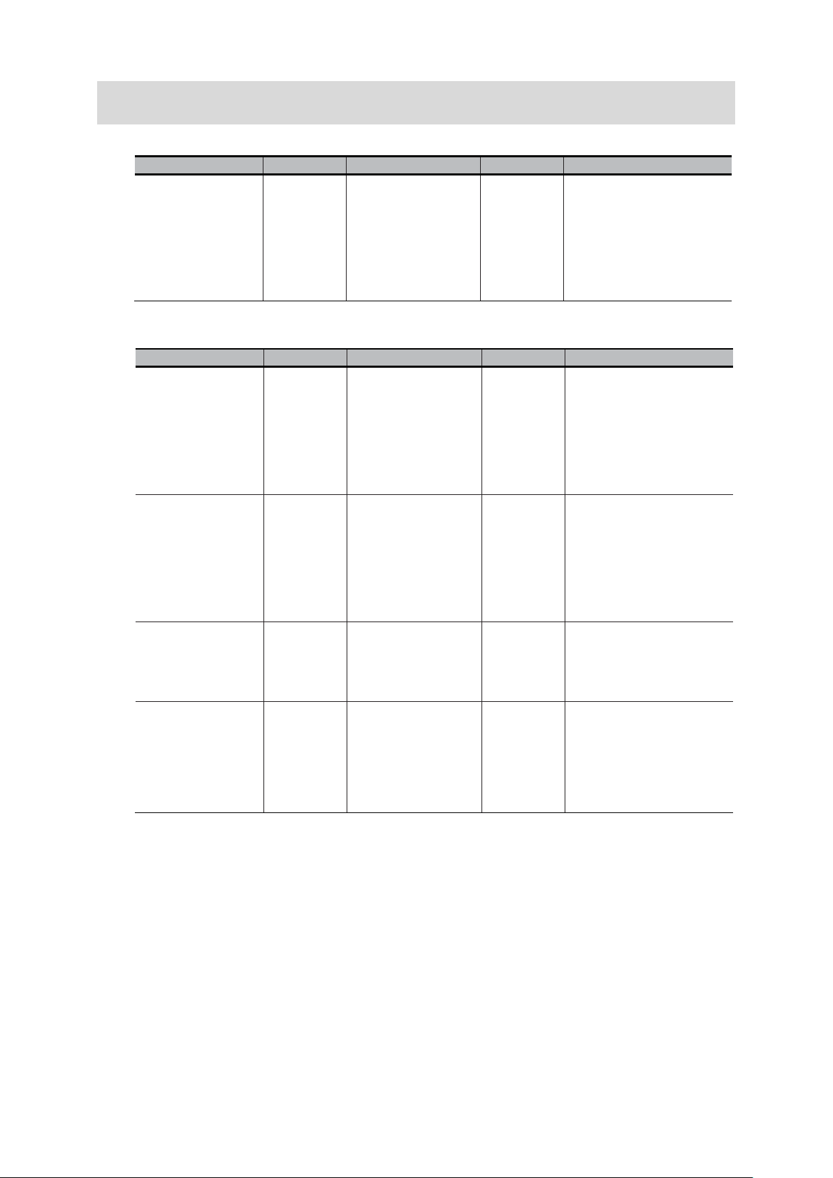
Name of Manual
Cat. No.
Model
Purpose
Contents
Regular Payload
Series Hardware
Installation Manual
I623
RT6-0□□□□□□
When User
Robot
Describes the
Medium & Heavy
Payload Series
Hardware
Installation Manual
I624
When User
Robot
Describes the
TMflow Software
Manual
-
When User
to configure
TMflow
Describes the software
TECHMAN ROBOT
Safety System 3.
Safety Manual
-
When User
Robot
Describes the safety
Name of Manual
Cat. No.
Model
Purpose
Contents
V
F
3
Application
Construction
Guide
Z446
FH-5050
When User
know about
Describes the soft
Related Manuals
<Application Construction Guide>
ision Sensor
H Series
D Robot Vision
<Robot Manual>
FH-SMDA-GS050B
RT6-1□□□□□□
RT6-2□□□□□□
want to
the FH
series 3D
robot vision
system.
want to
know the
setup and
hardware
specification
s of the TM
want to
know the
setup and
hardware
specification
s of the TM
functions, setup,
and operations to use FH
series 3D
robot vision system.
specifications, external
dimensions, names of
parts, I/O, installation,
and wiring of the
cooperative robot TM5.
specifications, external
dimensions, names of
parts, I/O, installation,
and wiring of the
cooperative robot TM12,
TM14.
3
I626
I648
want to
know how
Want to
Know the
Safety
Features of
the TM
functions, settings, and
operations for using the
collaborative robot TM.
functions in Collaborative
robot TM.
10
Page 13
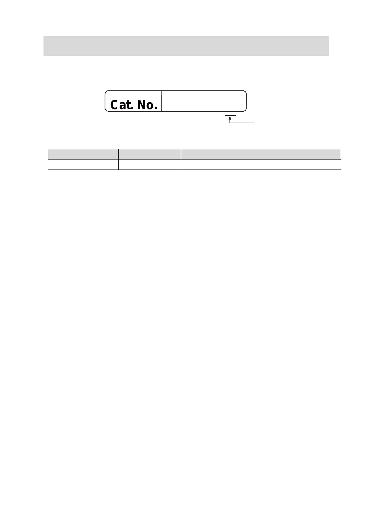
Cat. No.
Z447-E1-01
Revision History
A manual revision code appears as a suffix to the c atalog n umber on t he front and bac k cover s
of the manual.
Rev. Code Rev. Date Revision Contents
01 Feb. 2021 Original product
Revision code
11
Page 14
Procedure
Reference
Construction Guide] Chapter 6
Construction Guide] Chapter 7
Setting Communications for Robot controller
Refer to Chapter 3.1
Refer to Chapter 3.3
Construction Guide] Chapter 8
Description of the sample programs
Refer to Chapter 6
1. Overview
1.1. Overview
This manual describes procedures for connections and settings required for
constructing robot vision applications by connecting your robot controller to the
Vision Sensor FH (hereafter referred to as Vision Sensor).
Utilizing this manual and Robot Vision Application Construction Guide can reduce
man-hours to connect the Vision Sensor to your robot controller, set the Vision Sensor,
and create robot programs.
1.2. Instructions for Building a 3D Robot Vision Application
Please follow the flow below for constructing 3D robot vision applications
Creating Data Set for Robot Vision
↓
System Settings for the Vision Sensors
↓
↓
Connecting Vision Sensor to Robot Controller
↓
Robot Vision Settings for Vision Sensors
↓
[3D Robot Vision Application
[3D Robot Vision Application
Refer to Chapter 3.2
[3D Robot Vision Application
12
Page 15
Program
Project Name
Detail
Vision Sensor.
(hand) and to place the workpiece.
1.3. Robot Programs Covered in this Manual
The two types of robot programs covered in this manual are output from the Robot
Vision Dataset Output Tool. Each program is used for a different purpose.
Setup Program FHSETUPMAIN This program allows the Vision Sensor to
give operating instructions to the robot to
configure the Vision Sensor for robot
vision.
This program consists of the following
functions
- Send the current robot position to the
Vision Sensor.
- Move to the indicated position on the
Sample Program FHSAMPLEMAIN This program is a sample of the basic
program flow for a pick application.
In this program, the robot gives control
instructions to the Vision Sensor.
The program consists of the following
functions
- Connecting to the Vision Sensor
- Scene switching of the Vision Sensor
- Moving to the measurement position
- Registering the current robot position to
the Vision Sensor
- Execute measurement instructions to
the Vision Sensor
- Receives the position of the workpiece to
be recognized
- Move to approach position
- Move to the target work location
(grasping position)
Based on this program, a pick-and-place
application is built by adding the robot
movement to operate the end-effector
13
Page 16
Device name
Manufacture
Name
Model
Remarks
supported.
Vision Sensor
LAN Cable
(Straight cable)
Data set output tool
for 3D Robot Vision
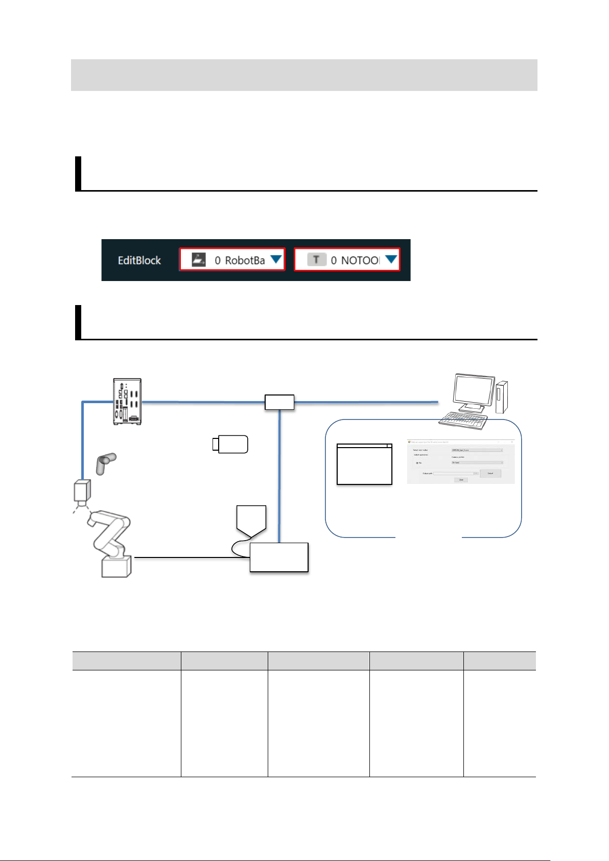
2. System Configuration
This chapter describes the system configuration and target devices to construct robot
vision applications.
2.1. Cautions f or Robot Equipment
[RobotBase] and [NOTOOL] have been selected for the robot controller's coordinate
system.
2.2. When Using Vision Sensor FH Series 3D Vision Sensor
2.2.1. System Configuration
Switching hub
PC
USB memory
Calibration Target
3DCamera
Robot
2.2.2. Target Devices
TeachingPendant
Robot Controller
TMflow
PC Software
Vision Sensor OMRON
Ve r. 6 . 40 or
later
Vision Sensor
FH Series
FH-5050
Controllers
other than
FH-5050 are
not
14
Page 17

3D Camera
OMRON
3D Vision Sensor
FH-SMDA-GS050B
resistance
FH-VSDX-LBX□M
Tar g e t
Tar g e t
Robot Vision
Software Installer
it.
obot Programing
TMflow
hub
d product
d product
evice except mentioned above for each device of the system
configuration.
For details, refer to manuals noted in Related Manuals.
Camera Cable OMRON
Camera I/O cable OMRON
OMRON
Calibration target
OMRON
3D Software OMRON
Robot OMRON
OMRON
PC software
Ethernet cable
super bending
I/O cable super
bending resistance
Handeye Calibration
Camera Calibration
3D
Collaborative Robot
TM5-700
TM5-900 RT6-0□□90□□
Data set output tool
for 3D robot vision
FHV-VNBX□M
FHV-VNLBX□M
FH-VSDX-BX□M
FH-XCAL-R -
FH-XCAL-S
FH-UM3D1 -
RT6-0□□70□□
-
-
-
-
Ver.1.00
Please
contact us for
how to obtain
R
OMRON
Switching hub OMRON
USB memory OMRON USB memory FZ-MEM8G
Environment
Industrial switching
-
W4S1-□□□
Precautions for Correct Use
Do not use any d
Additional Information
This manual does not provide operations, installation, and wiring methods for each
device.
Ver.1.80.530
0 or later
Recommende
Recommende
15
Page 18

Vision sensor. ▼
Communication
using PING command.
▼
sending and receiving commands.
3. Connecting Vision Sensor to Robot Controller
This chapter describes procedures to connect the Vision Sensor to the robot controller.
Please follow the flow below for the settings.
The IP address of each device is described below.
Vision Sensor : 10.5.5.100
Robot controller: 10.5.5.101
To change the robot's communication
settings, connect the monitor,
keyboard, and mouse to the robot
3.1
3.2
3.3 Verify Commands Sent/Received
Setting communications for the
robot controller
Verifying Ethernet
control box and activate the robot.
Use TMflow to change the robot's
default IP address to match the
communication settings set for the
Check the connection status of Ethernet
Run a robot program for startup to
establish the TCP/IP connection
between the Vision Sensor and the
robot controller.
Check the communication status by
16
Page 19

3.1. Setting Communications for Robot controller
Please follow the procedures below to set the communications for the robot controller.
Connect a monitor, keyboard, and mouse to the robot's control box, and turn on the
robot's power.
Click [Get Control] on the
robot startup screen to make
the settings available.
1
If the robot is in auto mode,
switch to manual mode.
Click the icon in the top left
menu to display a list of the
function menu.
2
Click [System] – [Network].
Click [Local Area Connection
X] in Network setting.
Set the IP Address and Subnet
Mask.
Set the IP address that does
3
not overlap with the Vision
Sensor and the PC where
TMflow is running.
17
Page 20

setting.
Vision to the USB memory.
"TMROBOT".
Click [OK] and Click an icon
enclosed in red square on the
right figure to close to Network
Copy the "TM_Export" folder in
the "RobotProgram" folder of
the data output from the Data
4
Set Output Tool for Robot
Change the device name of
the USB memory to
5
Connect the USB memory to
the USB port of the robot
controller.
6
Click the icon in the top left
menu to display a list of the
function menu.
7
Click
[System] – [Import/Export]
Click [import] in the top left
corner.
The right dialog will be
displayed, select “Configure
Controller” and click [Finish].
8
18
Page 21

For details, refer to manuals noted in Related Manuals.
In Robot List ,
select FHRobotVision and click
[OK].
Select all files that appear in
Project, Component.
Click [Import] at the bottom
right.
9
When the import is complete
and "Import complete" is
displayed, click [OK].
Additional Information
The device name of the USB flash drive is “TMROBOT”.
The program cannot be read with any other device name.
This manual does not provide operation, installation, and wiring methods for each
device.
19
Page 22

cables.
3.2. Connecting and Checking Vision Sensor and Robot Controller
Follow the procedures below to connect the Vision Sensor and the robot controller
and to check the connection status.
3.2.1. Verifying Ethernet Communication (FH Series Vision Sensor)
Connect the Vision Sensor and
the robot controller with LAN
1
(Operation of the Vision
Sensor)
Move the mouse cursor to
lower left of the window to
display [Start]. Select [Start]
2
- [All Programs] -
[Accessories] - [Command
Prompt] to launch [Command
Prompt].
(Operation of the Vision
Sensor)
Execute PING command to
the IP address of the robot
3
controller.
(Operation of the Vision
Sensor)
When 32-byte data could be
successfully sent/received
four times as shown in the
figure on the right, that
4
means that the
communications have been
established and the wiring and
settings of Ethernet is
correctly done.
20
Page 23

correct.
When 32-byte data cannot be
sent/received four times and
PING command timed out,
check whether or not the
robot controller is turned on,
the wiring was correctly done,
or communication settings are
21
Page 24

3.3. Verify Commands Sent/Received
Execute the setup program on the robot controller and follow the steps below to
confirm that commands can be sent and received from the Vision Sensor.
(Operation of TMflow)
On the robot controller side,
select [Project].
1
(Operation of TMflow)
Like shown on the right
figure,
On the project editing screen,
click the icon.
2
Select [FHSETUPMAIN] from
the list of projects and click
[OK] to load the setup
program.
(Operation of TMflow)
Like shown on the right
figure,
Click the icon to open the
configuration dialog for
[fhsetup] node.
3
22
Page 25

dialog.
save your network settings.
(Operation of TMflow)
Select [RecvString] to open
the Network Settings dialog.
Make sure that [Choose
Device] is set to FH.
Click [Edit Device] to open the
Device Settings screen.
4
Set the IP address and port
number of the Vision Sensor.
Click [Done] to save the
settings.
(Operation of TMflow)
Select [SendString] to open
the Network Settings dialog.
Make sure that [Choose
5
Device] is set to FH.
After confirming, close the
[fhsetup] node configuration
(Operation of TMflow)
Like shown on the right
figure,
6
Click the icon to save the
[FHSETUPMAIN] project to
23
Page 26

Vision Sensor
TMflow
W
Rx
P
Ry
R
Rz
(Operation of Robot Stick)
Press the [Play/Pause] button
on the robot stick to run the
project.
7
When the project is in the
running state, the robot's ring
will flash green.
(Operation of the Vision
Sensor and TMflow)
Like shown on the right
figure, when [Get] is clicked
on the Main Window of the
Vision Sensor and the current
robot position on TMflow is
displayed at the same position
on the Main Window of the
Vision Sensor,
sending/receiving commands
between them have been
succeeded.
8
* The current robot position
can be checked by clicking
[Controller] on the project
editing toolbar.
* Correspondence relation of
notation
24
Page 27

others.
stick to stop the project.
For details, refer to manuals noted in Related Manuals.
(Operation of the Vision
Sensor)
Like shown on the right
figure,
9
If the [Robot Error] button
turns red, the connection has
failed. Check the wiring and
(Operation of Robot Stick)
When the Vision Sensor and
the robot controller have
10
exchanged commands, press
the [Stop] button on the robot
Additional Information
This manual does not provide operation, installation, and wiring methods for each
device.
25
Page 28

Coordinate System
Meaning
System
origin
Local Coordinate System
User-defined coordinate system
of the robot
flange coordinates system.
and the Z axis is the optical axis of the camera.
4. Coordinate System
This chapter describes the coordinate system handled by the robot vision application.
4.1. Name of Coordinate System
The robot coordinate system of the Vision Sensor uses the name shown in the table
below.
Robot Base Coordinate
Flange Coordinate system Coordinate system defined on the flange surface
Tool Coordinate System The coordinate system is defined in the tool
Camera Coordinate System With the optical center of the camera as the
Coordinate system with the robot base as the
center point by offsetting the origin of the
starting point, the X and Y axes are the
horizontal and vertical directions of the image,
26
Page 29

Vision Sensor
OMRON TM Series
Local Coordinate System
Base Coordinate System
Tool Coordinate System
Tool Coordinate System
The orientation of the coordinate axes of each coordinate system depends on the robot.
Please refer to the instruction manual for each robot.
There are the following differences between the names of the coordinate system in the
Vision Sensor and the coordinate system in the OMRON TM series.
27
Page 30

the list of projects and click
to load the setup
Press the [Play/Pause] button
on the robot stick to run the
5. How to Start the Setup Program
This chapter describes how to start the setup program. To set the robot vision of
the Vision Sensor, the setup program must be running on the robot side. Establish
the connection between the Vision Sensor and the robot controller by [3. Connecting
Vision Sensor to Robot Controller]
(Operation of TMflow)
Like shown on the right figure,
On the project editing screen,
click the icon.
Select [FHSETUPMAIN] from
1
[OK]
program.
(Operation of Robot Stick)
project.
2
When the project is in the
running state, the robot's ring
will flash green.
28
Page 31

Connecting the Vision Sensor to the robot controller
Switching scenes on the Vision Sensor
Moving the robot to the image position
Register the current robot position in the Vision Sensor
Executing measurements on the Vision Sensor
Getting the measurement results
Moving the robot to the robot command position at measurement
(Driving the robot etc.)
2) Command response
(Measurement value etc.)
(Measurement etc.)
Program
6. Description of the Sample Programs
This chapter describes design examples of robot programs to construct applications
using the sample program.
You can understand how to implement a robot program to control the Vision Sensor
as shown in the following figure.
Vision Sensor
Robot
3) Command execution
Switching hub
Robot controller
1) Control command
Execution
Sample
PC
The sample program is implemented with the following procedures. When building
an actual application, design, implement and test the robot program, utilizing the
functions described in Chapter 7.
6.1
6.2
▼
▼
6.3
▼
6.4
▼
6.5
▼
6.6
▼
6.8
29
Page 32

Precautions for Correct Use
measurement values.
The implementation procedures for robot programs noted in this chapter are a
reference. You should design, implement, and test actually operating robot programs
based on your specific environment and applications.
In the Main Window or “Layout setup” of the Vision Sensor, check that the “Output”
of the current layout is ON. If the setting were OFF, the Vision Sensor will not output
30
Page 33

setting for each node.
fhrunsendcmd Component
fhdefglobal Component
6.1. Initialization of the Sample Program
This section describes how to initialize global variables, set the IP address and port
number of the Vision Sensor.
Open [FHSAMPLEMAIN] sub-
1
flow in the Project Edit page.
The [fhdefglobal] component
is placed at the beginning of
the flow.
This component initializes the
2
global variables needed to
communicate with the Vision
Sensor.
Select the ChangeScene node
on the flow and click the
pencil icon to open the
settings dialog box.
Click [SendString] and make
sure that [Choose Device] is
" F H ".
Click Edit Device and set the
3
IP address and port number
of the Vision Sensor.
Click [Done] to close the
dialog box.
The communication device
“FH” is commonly used in the
sample program.
It is not necessary to
configure the communication
31
Page 34

rCode].
Number of command
Commad
S
fhrunsendcmd Component
6.2. Switching Scenes on the Vision Sensor
Sends a scene switching command to the Vision Sensor and receives the response to
that command.
Select the [ChangeScene]
node on the flow and click the
1
pencil icon to open the
settings screen.
Click [input Argument] to
open the configuration dialog
box.
Click [Variables(7)] to open
the Variables configuration
dialog box.
Make sure that [cmdName] is
2
[SCENE].
Sets the scene number to be
used for [cmdArg[0]]
argument.
arguments
Non-procedure
Communication
cene Number
3
Check for the error in the
[ChangeScene] node.
The error is stored in the
global variable
[g_FHRobotVision_OMRON_er
32
Page 35

proceed to the next node.
next node.
fhrunrecvres Component
If the error code is 0 (zero),
proceed to the next node.
The [RecvResponse] node
receives the response to the
4
scene switching command.
Check for the error in the
[RecvResponse] node.
The error is stored in the
global variable
5
[g_FHRobotVision_OMRON_er
rCode].
If the error code is 0 (zero),
Check the execution result
(command response) of the
[RecvResponse] node.
The result of the execution is
stored in the global variable
6
[g_FHRobotVision_OMRON_p
aram[0]].
If the result of the execution
is 1 (OK), then proceed to the
33
Page 36

6.3. Moving Robot to Robot Image Position
Move the robot to the imaging position and register the imaging position in the
variable.
Move the robot to the imaging
position.
1
Click [Point Manager] to open
the dialog box.
Select [imgPos] and click the
pencil icon.
2
Click [Overwrite new pose to
this point] to record the
current robot position in
[imgPos]
34
Page 37

Point Node
Click [X] to close the Point
Manager dialog.
At the [imgPos] point node,
the robot moves to the
imaging position.
WARNING
3
These operations drive the robot.
Operate the robot in the state whereby pressing the
[Emergency stop] button can stop its motion anytime.
In the base list, select [RobotBase] as the current base.
In the tool list, select [NOTOOL] as the current tool.
35
Page 38

proceed to the next node.
fhsample_regpos Component
fhrunsendcmd Component
6.4. Register the Current Robot Position in the Vision Sensor
To register the current robot position to the Vision Sensor, use "fhsample_regpos".
The [RegistCurPos] node
registers the current robot
1
position to the Vision Sensor.
Check for the error in the
[RegistCurPos] node.
The error is stored in the
global variable
2
[g_FHRobotVision_OMRON_err
Code].
If the error code is 0 (zero),
6.5. Executing Measurements on Vision Sensor
Send the measurement command to the Vision Sensor and receives a response to
that command.
Click the [MEASURE] node to
open the configuration dialog
1
box.
Click the [inputArgument] to
open the configuration dialog
box.
2
Click [Variables(7)] to open
the Variables configuration
dialog box.
36
Page 39

proceed to the next node.
proceed to the next node.
fhrunrecvres Component
Number of command
Make sure that [cmdName] is
[MEASURE].
By executing the [MEASURE]
arguments
node, measurement command
is sent to the Vision Sensor.
Check for the error in the
[MEASURE] node.
The error is stored in the
global variable
3
[g_FHRobotVision_OMRON_err
Code].
If the error code is 0 (zero),
The [RecvResponse] node
receives the response to the
4
measurement command.
Non-procedure
Communication
Commad
Check for the error in the
[RecvResponse] node.
The error is stored in the
global variable
5
[g_FHRobotVision_OMRON_err
Code].
If the error code is 0 (zero),
37
Page 40

next node.
If the error code is 0 (zero),
fhrunrecvval Componrnt
Check the execution result
(command response) of the
[RecvResponse] node.
The result of the execution is
stored in the global variable
6
[g_FHRobotVision_OMRON_pa
ram[0]].
If the result of the execution is
1 (OK), then proceed to the
6.6. Getting the Measurement Results
The Vision Sensor measurements are received using "fhrunrecvval". In this sample
program, it is assumed that the Vision Sensor measurements are sent in the order
"TJG X Y Z W P R".
The [RecvVal] node receives
the measurement result of the
Vision Sensor and stores it in
the
g_FHRobotVision_OMRON_par
am[0-6].
1
Each element contains the
measurement results as shown
in the table on the right.
g_FHRobotVision_OMRON_param[0]
g_FHRobotVision_OMRON_param[1]
g_FHRobotVision_OMRON_param[2]
g_FHRobotVision_OMRON_param[3]
g_FHRobotVision_OMRON_param[4]
g_FHRobotVision_OMRON_param[5]
g_FHRobotVision_OMRON_param[6]
TJG
X
Y
Z
W
P
R
Check for the error in the
[RecvResponse] node.
The error is stored in the
global variable
2
[g_FHRobotVision_OMRON_err
Code].
38
Page 41

the program.
Set Node
Set Node
proceed to the next node.
Check the TJG of the Vision
Sensor measurement result.
The TJG of the Vision Sensor
measurement result is stored
in the global variable
[g_FHRobotVision_OMRON_pa
3
ram[0]].
If TJG is OK (1), proceed to
the next node, otherwise exit
6.7. Moving Robot to Robot Command Position at Measurement
Using the measurement results of the Vision Sensor the robot is moved to Robot
Command Position via the approach position.
The [SetCmdPos] node sets
the results of the Vision Sensor
measurements to the point
variable [resCmdPos].
You can grip the Robot
Command position of the point
1
variable [resCmdPos].
Select the [SetApproDist] node
and click the pencil icon to
open the Settings dialog box.
2
Click [Variables(1)] and set the
approach distance to
var_approDist.
39
Page 42

base coordinate system.
Point Node
Point Node
Set Node
The approach position is the
point of access to the Robot
Command position.
The approach distance is the
offset value in the Z
direction(mm) in the robot
The [SetApproPos] node
calculates the approach
position by adding the
approach distance in the Z+
3
direction from the robot
command position.
The [aproPos] node moves the
robot to the approach position.
Then, move to the robot
command position
[resCmdPos]. At this position,
the workpiece can be grasped.
The sample program ends
after moving to the robot
4
command position.
These operations drive the robot.
Operate the robot in the state whereby pressing the
[Emergency stop] button can stop its motion anytime.
WARNING
In the base list, select [RobotBase] as the current base.
In the tool list, select [NOTOOL] as the current tool.
40
Page 43

Component Name
Description
Reference
fhdefglobal
Initialize a global variable.
Chapter 7.3.1
Register the current robot coordinates to the
Vision Sensor
Sensor
Sensor
fhrunrecvval
Receive numerical data from the Vision Sensor
Chapter 7.3.5
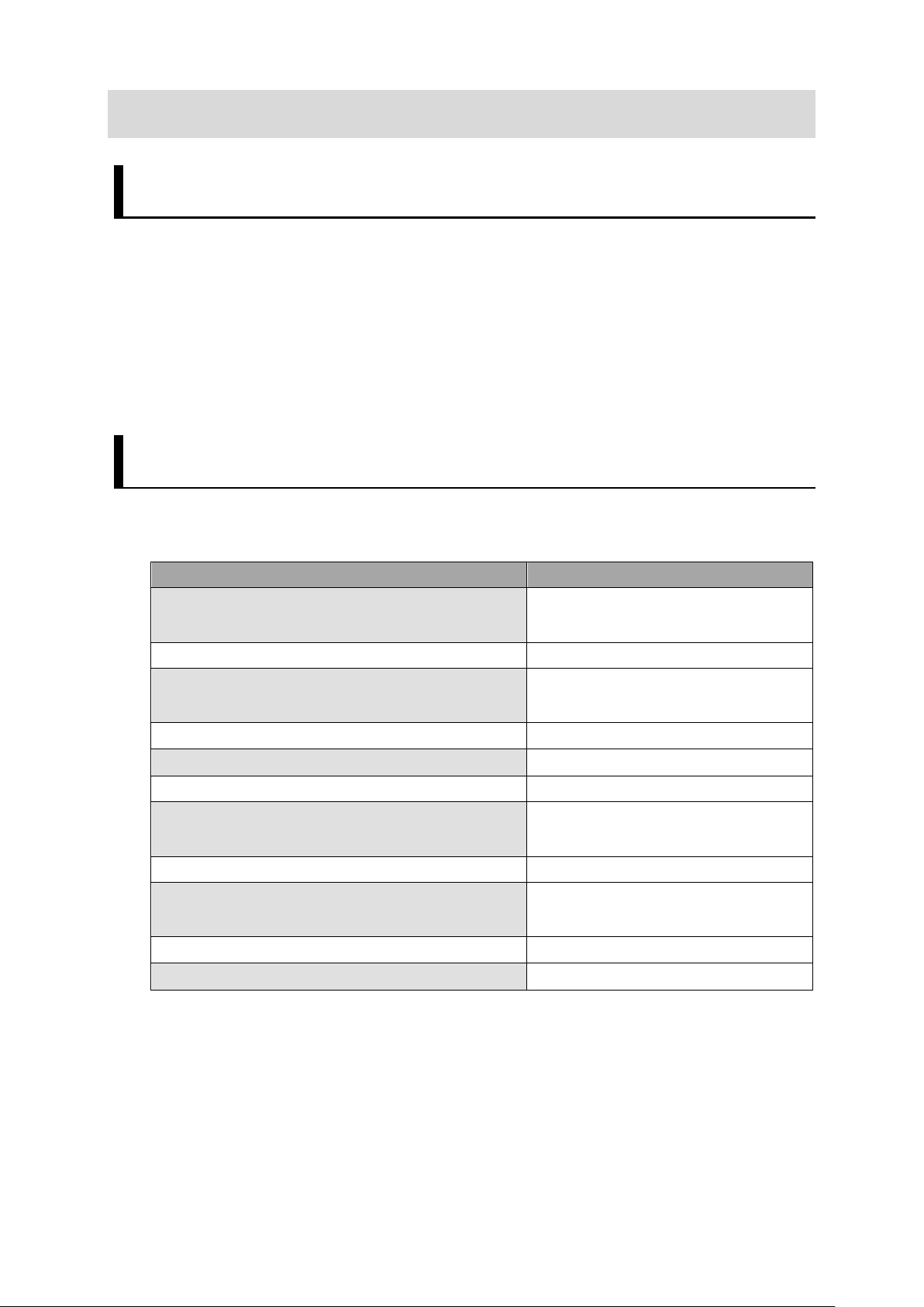
7. Component Reference
This chapter describes the functions for building a robot vision application
7.1. List of Components
This is a list of functions that can be used by the actual driving robot program.
fhsampleregpos
fhrunsendcmd Send a no-procedure command to the Vision
fhrunrecvres Receive a command response from the Vision
7.2. Error Message
The error message will be displayed on the DisplayBoard of TMflow.
Chapter 7.3.2
Chapter 7.3.3
Chapter 7.3.4
41
Page 44

Initialize global variables
7.3. Component Details
7.3.1. fhdefglobal
Function
Initialize a global variable.
Input Parameters
None
Output Parameters
None
Exit Process
This component has one exit node as follows
NoError : Normal termination.
Remarks
Define the global variables that are necessary to use the robot application.
Return Value
None
Precautions
Be sure to call this function before using any other function.
Example
The following example initializes a global variable.
42
Page 45

Communication Settings for the Vision
Sensors
WaitTime
int
Communication waiting time(ms)
Communication Settings for the Vision
Sensors
WaitTime
int
Communication waiting time(ms)
Er r. N o .
Error Message
Description
0 - normal termination
1800
-1601
ERROR:fhsendstring():NO_DATA:-1601
Send string length 0
1601
1602
-1301
ERROR:fhrecvstring():NO_CONNECT-1301
Unconnected state
7.3.2. fhsampleregpos
Function
Register the current robot position to the Vision Sensor.
Input Parameters
Setting Node Setting Target Data Typ e Description
SendString ChooseDevice device
RecvString ChooseDevice device
Output Parameters
None
Exit Process
There are two exit nodes in this component as follows
NoError : Normal termination.
Error : Abnormal termination (Please check the message displayed in the view window.)
Remarks
Get the current position of the robot in accordance with the selected coordinate system
number and register the current position to the Vision Sensor.
Return an error if this function is called while the Vision Sensor is not connected.
Returns an error if a response of current position registration failure is received from the
Vision Sensor.
Return value
-1800
-1601 ERROR:fhsendstring():NO_CONNECT:-
-1602 ERROR:fhsendstring():STRING_LEN:-
ERROR:fhsampleregpos():Trigger NG:-
Response NG
Unconnected state
Send string length over
43
Page 46

-1301
ERROR:fhrecvstring():NO_DATA:-1301
Receive data length 0
-1302
ERROR:fhrecvstring():STRING_LEN:-1302
Receive data length over
Registration of the current robot position in the Vision Sensor
Precautions
None
Example
In the following example, the current robot position is registered to the Vision Sensor.
44
Page 47

Type
ChooseDevice
device
Communication Settings for the Vision Sensors
WaitTime
int
Communication waiting time(ms)
to be sent to the Vision Sensor (0 to 5)
procedural commands to be sent to the
Vision Sensor
to the Vision Sensor(string).
to the Vision Sensor(string).
to the Vision Sensor(string).
to the Vision Sensor(string).
to the Vision Sensor(string).
command
argument 1
argument 1
argument n(*2)
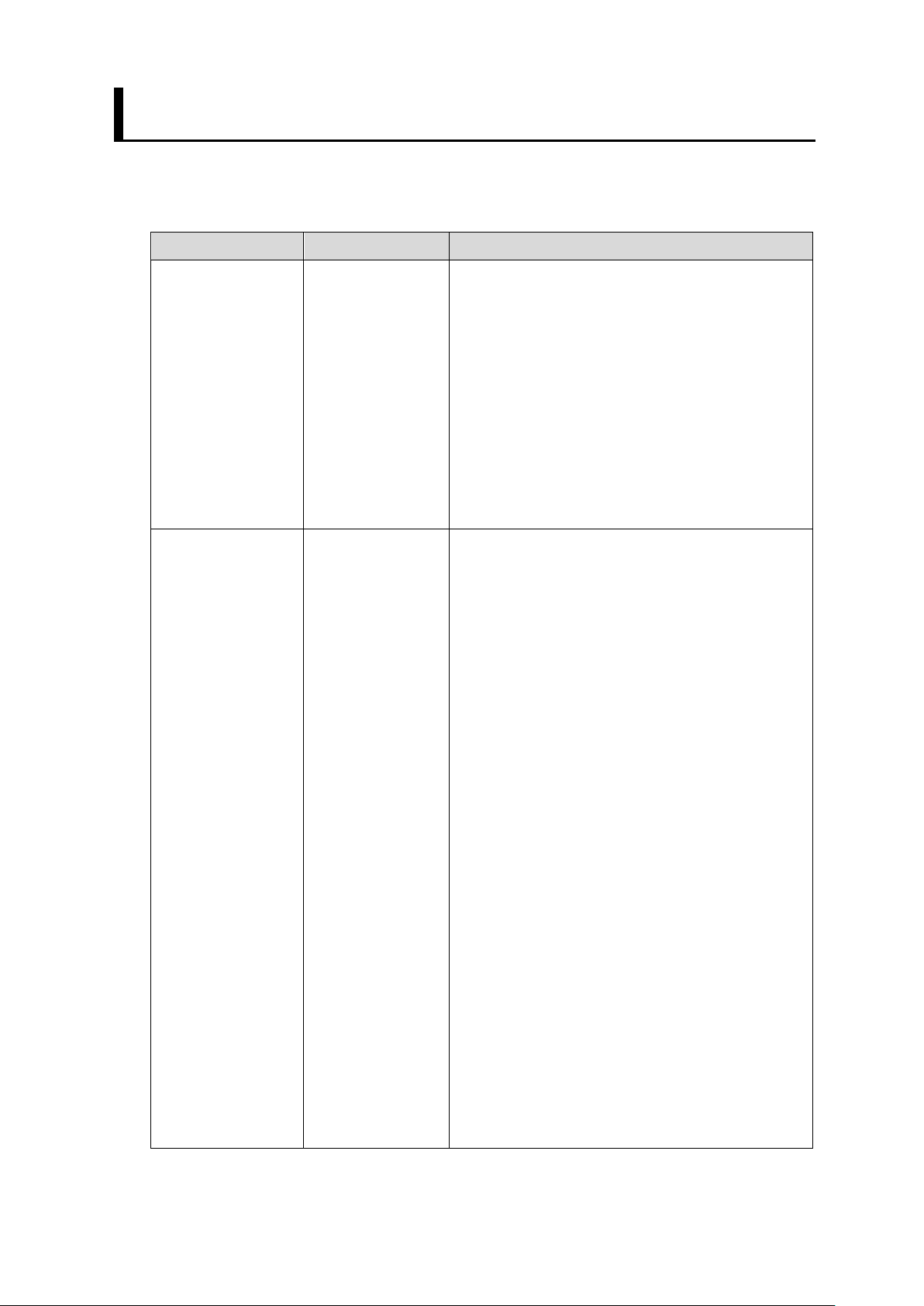
7.3.3. fhrunsendcmd
Function
Send a no-procedure command to the Vision Sensor
Input Parameters
Setting Node Setting Target Data
Description
SendString
inputArgument cmdArgNum int Number of no-procedural command arguments
cmdName String No-
cmdArg[0] String Argument 1 of the no-procedure command sent
cmdArg[1] String Argument 2 of the no-procedure command sent
cmdArg[2] String Argument 3 of the no-procedure command sent
cmdArg[3] String Argument 4 of the no-procedure command sent
cmdArg[4] String Argument 5 of the no-procedure command sent
Output Parameters
None
Exit Process
There are two exit nodes in this component as follows
NoError : Normal termination.
Error : Abnormal termination (Please check the message displayed in the view window.)
Remarks
Sends a no-procedure command to the Vision Sensor, concatenating the parameters
according to the following format.
If the number of no-protocol command arguments is out of the input range, an error is
returned.
<Format>
No-protocol
SP(*1)
Command
SP
Command
SP …
Command
45
Page 48

Er r. N o .
Error Message
Description
0 - normal termination
input range.
-1601
ERROR:fhsendstring():NO_CONNECT:-1601
Unconnected state
-1601
ERROR:fhsendstring():NO_DATA:-1601
Send string length 0
-1602
ERROR:fhsendstring():STRING_LEN:-1602
Send string length over
No-procedure command name
argument 1
*1: “SP” is space
*2: The command argument n depends on the number of non-procedural command
arguments.
Return Value
-1506 ERROR:fhrunsendcmd():Invalid Command
Argument No.:-1506
The number of non-
procedural command
arguments is out of the
Precautions
The length of the string of the no-stepping command that can be sent is 127 bytes (not
including the delimiter).
Set the input parameters so that the string length of the no-procedure command does
not exceed 127 bytes.
Example
In the following example, we will switch to scene number 5.
Number of arguments of the no-
procedure command
No-procedure command
46
Page 49

Setting Node
Setting Target
Data Type
Description
Communication Settings for the Vision
Sensors
WaitTime
int
Communication waiting time(ms)
Type
than "OK")
Other than 0: Error)
Er r. N o .
Error Message
Description
0 - normal termination
-1301
ERROR:fhrecvstring():NO_CONNECT:-1301
Unconnected state
-1301
ERROR:fhrecvstring():NO_DATA:-1301
Receive data length 0
-1302
ERROR:fhrecvstring():STRING_LEN:-1302
Receive data length over
7.3.4. fhrunrecvres
Function
fhrunrecvres
Input Parameters
RecvString ChooseDevice device
Output Parameters
Variable Name Data
g_FHRobotVision_OMRON_param float[] param[0] : Command Response Results
g_FHRobotVision_OMRON_errCode int Execution Result(0: Normal termination
Exit Process
There are two exit nodes in this component as follows
NoError : Normal termination.
Error : Abnormal termination (Please check the message displayed in the view window.)
Remarks
Receive the response (command response) to the no-procedure command sent to the
Vision Sensor.
If the command response is OK, assign 1 to the global variable
Description
(1: Command response "OK" - 1: other
g_FHRobotVision_OMRON_param[0].
If the command response is not OK, assign "-1" t o the global variable
g_FHRobotVision_OMRON_param[0].
Return Value
47
Page 50

Precautions
None
Example
In the following example, the response to the measurement command is received and if
the command response is not OK, the program is terminated.
Send MEASURE Command
Receives a command response to “MEASURE” command.
Check if the error number is 0.
The expression "g_FHRobotVision_OMRON_param[0] == 1"
to check if the command response is OK
48
Page 51

Setting Node
Setting Target
Data Type
Description
Communication Settings for the Vision
Sensors
WaitTime
int
Communication waiting time(ms)
Type
param[9] : Received numeric
data 0 - 9)
Other than 0: Error)
The string before conversion
The result of the analysis after conversion
abc
0
123abc
123
abc123
0
1.00E+03
1000
7.3.5. fhrunrecvval
Function
Receive numerical data from the Vision Sensor
Input Parameters
RecvString ChooseDevice device
Output Parameters
Variable Name Data
g_FHRobotVision_OMRON_param float[] param[0] -
g_FHRobotVision_OMRON_errCode int Execution Result(0: Normal termination
Exit Process
There are two exit nodes in this component as follows
NoError : Normal termination.
Error : Abnormal termination (Please check the message displayed in the view window.)
Remarks
This function stores the numerical data sent from the Vision Sensor into the global
variable "g_FHRobotVision_OMRON_param".
This function outputs up to 10 values.
If there are more than 11 numbers, this function outputs only the first 10.
Description
If the length of the segmented string is longer than 12 bytes, this function returns an
error of abnormal parameter length.
Returns an error if the number of numeric data is zero.
The following is an example of the output when a string is included.
<Conversion example>
49
Page 52

Er r. N o .
Error Message
Description
0 - normal termination
-1301
ERROR:fhrecvstring():NO_CONNECT:-1301
Unconnected state
-1301
ERROR:fhrecvstring():NO_DATA:-1301
Receive data length 0
-1302
ERROR:fhrecvstring():STRING_LEN:-1302
Receive data length over
Result Output (Message) Processing Item
measurement results
Setting Target
Setting details
Output device
IoModule2: Serial (Ethernet)
-
Termination string
∖r (Carriage Return)
-
Delimiter string
∖x20 (Space)
-
[9]
Return Value
Precautions
The maximum length of the string to be received is 127 bytes (not including the delimiter).
if more than 128 bytes are received, an error is returned.
The measurement result received from the Vision Sensor will be stored in the
g_FHRobotVision_OMRON_param.
To get the measurement result with this function, Result Output (Message) must be
placed in the flow, and the settings must be as follows
The destination of the received
Output Data 0 - 9 numerical data(*1) g_FHRobotVision_OMRON_param
[0] -
g_FHRobotVision_OMRON_param
*1: The output data format should be set as follows
- Data type: Number
- Digits of integer: 6
- Digits of decimal: 4
50
Page 53

Example
In the following example, the robot moves after receiving the measurement result of the
Vision Sensor (grasping position X, Y, Z, W, P, R).
Receive the results of the Vision Sensor measurements
Check if the error number is 0.
Store the received results in a Point
Move Robot
51
Page 54

Authorized Distributor:
In the interest of product improvement,
specifications are subject to change without notice.
Cat. No. Z447-E1-01
0221
© OMRON Corporation 2021 All Rights Reserved.
OMRON Corporation Industrial Automation Company
OMRON ELECTRONICS LLC
2895 Greenspoint Parkway, Suite 200
Hoffman Estates, IL 60169 U.S.A.
Tel: (1) 847-843-7900/Fax: (1) 847-843-7787
Regional Headquarters
OMRON EUROPE B.V.
Wegalaan 67-69, 2132 JD Hoofddorp
The Netherlands
Tel: (31)2356-81-300/Fax: (31)2356-81-388
Contact: www.ia.omron.com
Kyoto, JAPAN
OMRON ASIA PACIFIC PTE. LTD.
No. 438A Alexandra Road # 05-05/08 (Lobby 2),
Alexandra Technopark,
Singapore 119967
Tel: (65) 6835-3011/Fax: (65) 6835-2711
OMRON (CHINA) CO., LTD.
Room 2211, Bank of China Tower,
200 Yin Cheng Zhong Road,
PuDong New Area, Shanghai, 200120, China
Tel: (86) 21-5037-2222/Fax: (86) 21-5037-2200
 Loading...