

Page 1

Page 2

F400
Color Vision Sensor
Introduction Manual
Produced June 1999
1
Page 3
About this Manual:
This manual describes the features and basic operations of the F400 Color Vision
Sensor. This is one of three manuals used to operate the F400. Refer to the following
table for the contents of each manual.
Manual
1: Introduction Manual
2: Setup Manual
3: Operation Manual
Please read the above manuals carefully and be sure you understand the information provided before attempting to install
or operate the F400.
Describes F400 capabilities and basic
operating procedures for beginners by
using typical applications.
Provides information on system hardware
and installation.
Describes operation of the F400, including
setting of criteria, communication with
external devices, etc.
Contents Catalog No.
Z131-E1-1
Z130-E1-1
Z135-E1-1
WARNING
Failure to read and understand the information provided in this manual may result in
personal injury or death, damage to the product, or product failure. Please read each section
in its entirety and be sure you understand the information provided in the section and related
sections before attempting any of the procedures or operations given.
2
Page 4
TABLE OF CONTENT
General Precautions, Visual Aids 4
○○○○○○○○○○○○○○○○○○○○○○○○○○○○
SECTION 1 FEATURES 5
1-1 Pickup Mode 6
1-2 Color Filter Mode 8
○○○○○○○○○○○○○○○○○○○○○○○○○○○○○○
○○○○○○○○○○○○○○○○○○○○○○○○○○○○○○○
SECTION 2 MEASUREMENT 11
2-1 Starting and Quitting 12
2-2 Surface Def ects on Bottle Caps 14
2-2-1 Changing Operating Mode 15
2-2-2 Selecting Scene Mode 16
2-2-3 Adjusting Images 17
2-2-4 Setting Measurement Region 19
2-2-5 Measuring Objects 21
Fore more stable measurements 22
○○○○○○○○○○○○○○○○○○○○○○○○○○○○○
○○○○○○○○○○○○○○○○○○○○○○○
○○○○○○○○○○○○○○○○○○○○○○○○○○○
○○○○○○○○○○○○○○○○○○○○○○○○○○○○
○○○○○○○○○○○○○○○○○○○○○○○○○○○○○○○
○○○○○○○○○○○○○○○○○○○○○○○○○
○○○○○○○○○○○○○○○○○○○○○○○○○○○○○○
○○○○○○○○○○○○○○○○○○○○○○○○○○
2-3 Ice Cream Separation 24
2-3-1 Changing Operating Mode 25
2-3-2 Selecting Scene Mode 26
2-3-3 Adjusting Images 27
2-3-4 Setting Measurement Region 29
2-3-5 Setting Output 32
2-3-6 Checking Measurements 35
2-3-7 Measuring Objects 37
○○○○○○○○○○○○○○○○○○○○○○○○○○○○○
○○○○○○○○○○○○○○○○○○○○○○○○○○
○○○○○○○○○○○○○○○○○○○○○○○○○○○○
○○○○○○○○○○○○○○○○○○○○○○○○○○○○○○
○○○○○○○○○○○○○○○○○○○○○○○○○
○○○○○○○○○○○○○○○○○○○○○○○○○○○○○○○○
○○○○○○○○○○○○○○○○○○○○○○○○○○
○○○○○○○○○○○○○○○○○○○○○○○○○○○○○○
SECTION 3 Appendix - Peculiarity of Color 39
SECTION 4 Samples of Measurement Objects 44
3
Page 5

General Precautions
The user must operate the product according to the performance specifications described in the operation manuals.
Before using the product under conditions which are not described in the manual or applying the product to nuclear control
systems, railroad systems, aviation systems, vehicles, combustion systems, medical equipment, amusement machines,
safety equipment, and other systems, machines, and equipment that may have a serious influence on lives and property if
used improperly, consult your OMRON representative.
Make sure that the ratings and performance characteristics of the product are sufficient for the systems, machines, and
equipment, and be sure to provide the systems, machines, and equipment with double safety mechanisms.
Visual Aids
The following headings will help you locate different types of information.
Note Indicates information of particular interest for efficient and convenient operation of the product.
Indicates pages where additional information can be found.
Indicates a procedure. The step numbers in the procedure correspond to the numbers in any
1
related illustrations.
© OMRON, 1999
All rights reserved. No part of this publication may be reproduced, stored in a retrieval system, or transmitted, in any form, or by any means,
mechanical, electronic, photocopying, recording, or otherwise, without the prior written permission of OMRON. No patent liability is assumed with
respect to the use of the information contained herein. Moreover, because OMRON is constantly striving to improve its high-quality products, the
information contained in this manual is subject to change without notice. Ever y precaution has been taken in the preparation of this manual.
Nevertheless, OMRON assumes no responsibility for errors or omissions. Neither is any liability assumed for damages resulting from the use of
the information contained in this publication.
4
Page 6

SECTION 1
F400 measures the image using color information of color image.
Select a scene mode out of two processing modes, "color pickup
mode" and "color filter mode", according to the application.
The information contained in this section is about scene mode.
FEATURES
5
Page 7
1-1 Color Pickup Mode
Possible to measure the several colors at the same time.
<Applications>
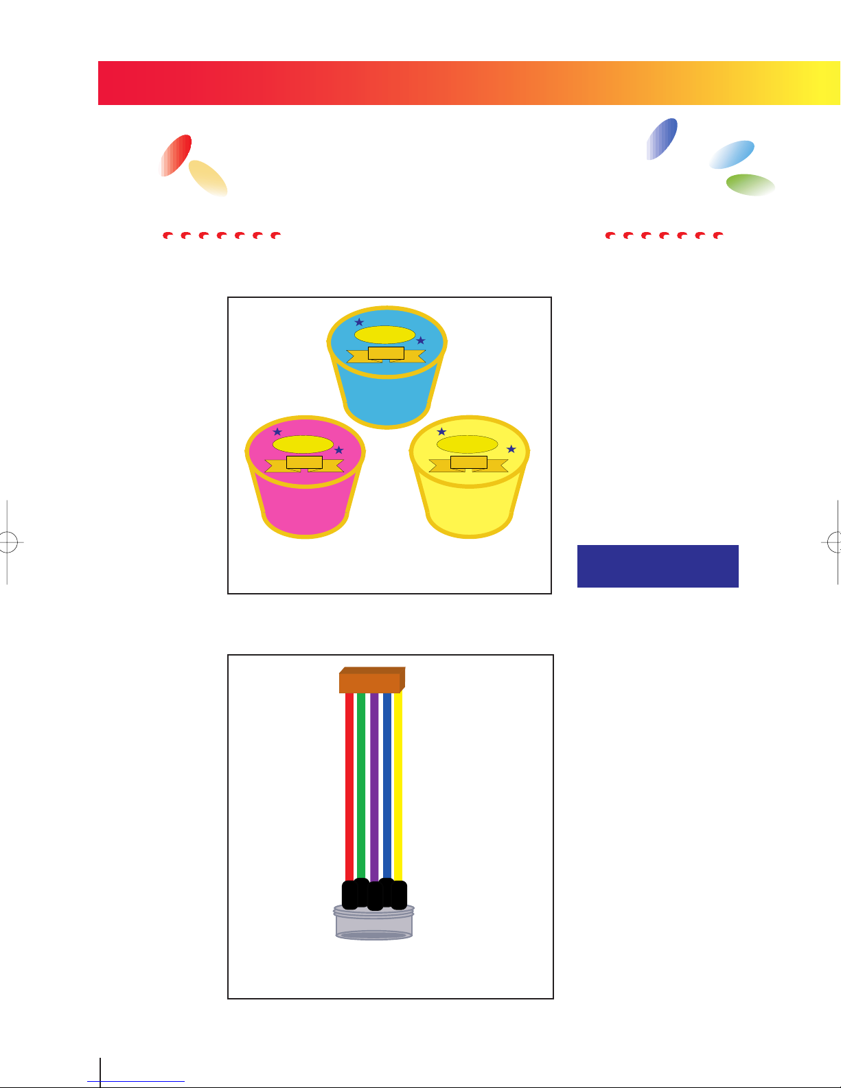
● Separation by colors
OMRON
Ice Cream
Vanilla
OMRON
Ice Cream
Strawberry
OMRON
Ice Cream
Lemon
Ice creams will be separated by the colors of the lids.
● Miswiring check of wire harnesses
Settings -> p.24
Miswiring can be checked b y registering all colors of
the wire harnesses.
6
Page 8
<How to convert the image>
●
Select the color to be picked up from color image. (Up to 8 colors can be registered.)
(Ex.) When red is selected.
Binarized
● Select the color to be inspected by region.
Region 0: Only red will be regarded as
inspection object.
Region 1: Only green will be regarded
as inspection object.
Only red will be picked up .
Other colors will turn black.
● Can distinguish between "shaded pink" and "red".
Even if at the end of a part of pink faded out. Only pink will be picked up.
7
Page 9
1-2 Color Filter Mode
Stable measurement of the object that is
hardly detected in monochrome image.
<Applications>
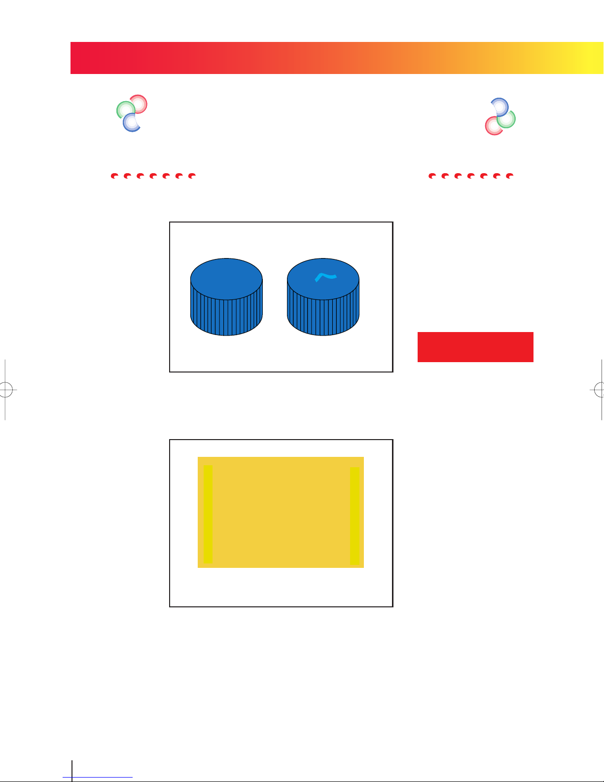
● Detection of surface defect
Surface defects on bottle caps .
● Amount of adhesive.
Inspect the amount of adhesive that has been coated on metal board.
Settings -> p.14
8
Page 10
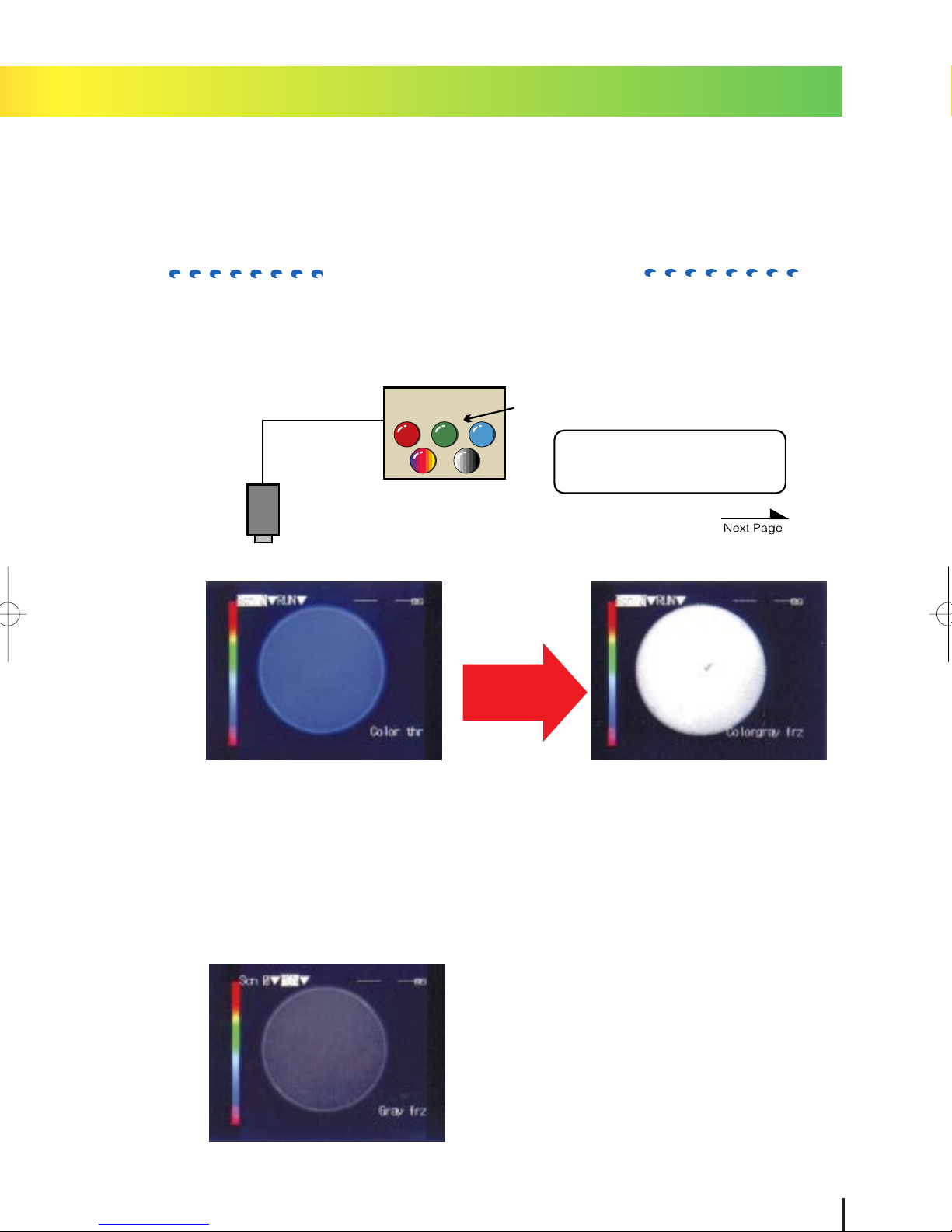
<How to convert the image>
●Can convert the image into gray image enhancing specific color using the
built-in color filter.
Camera
F400
Convert into gray
image of 256 gradations.
Color filter can be switched electrically
Variety of color filter is
on the next page.
The color to be detected will be displayed
lightly .
●For only light and shade are used to process in former monochrome image, detection is hardly executed.
9
Page 11
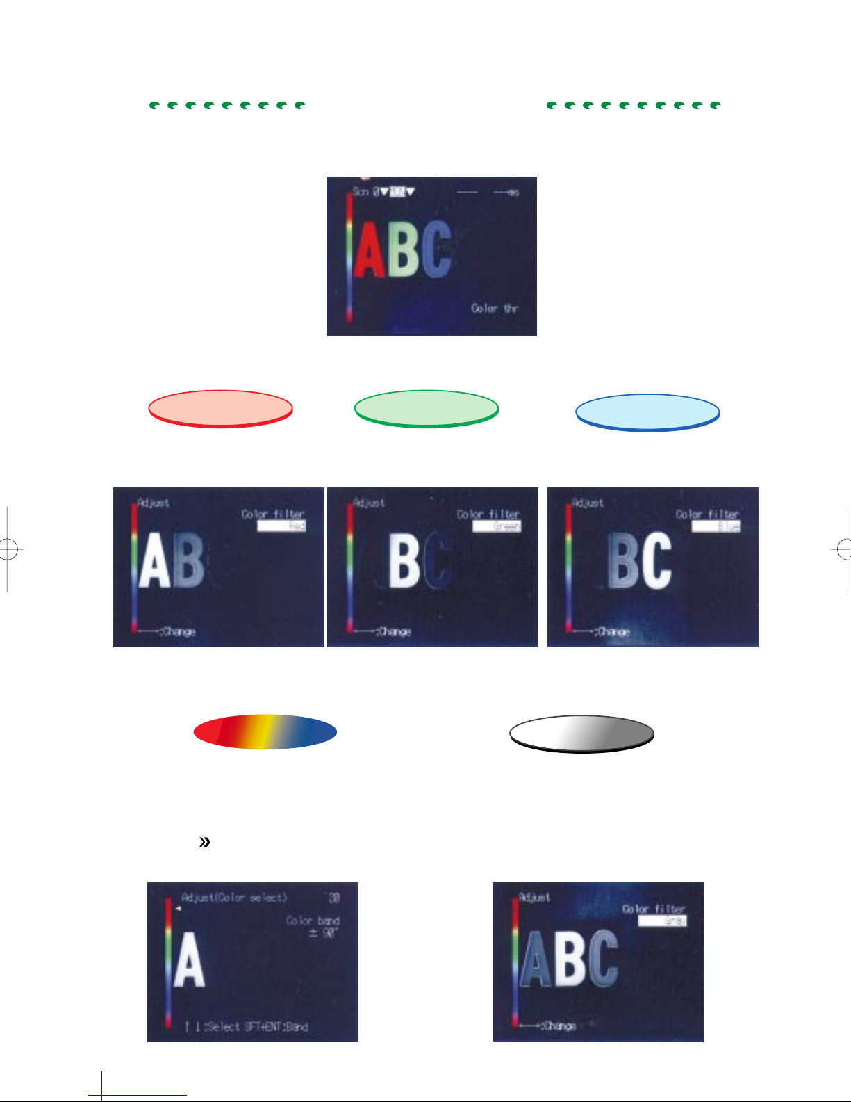
Blue filter
Gray filter
<Color filters>
Color image read by camera
Red filter
Take an effect the same as using optical red filter.
Red will be displayed lightly.
Take an effect the same as using optical green filter.
Green will be displayed lightly.
Colorgray filter
The filter can be arranged according to the color
to be detected. Light will be changed in accordance with hue.Use the filter with understanding of peculiarity of color.
Appendix
(Ex.) Measured color: red
Peculiarity of color (p .39)
Green filter
Take an effect the same as using
optical blue filter.
Blue will be displayed lightly.
Gray filter will conver t the image into former
gray image (monochrome image based on light
and shade of color).Use this filter when measurement monochromatic image such as black,
white and gray.
10
Page 12

SECTION 2
This section describes basic operations of F400 with typical applications.
MEASUREMENT
11
Page 13
2-1 Starting and Quitting
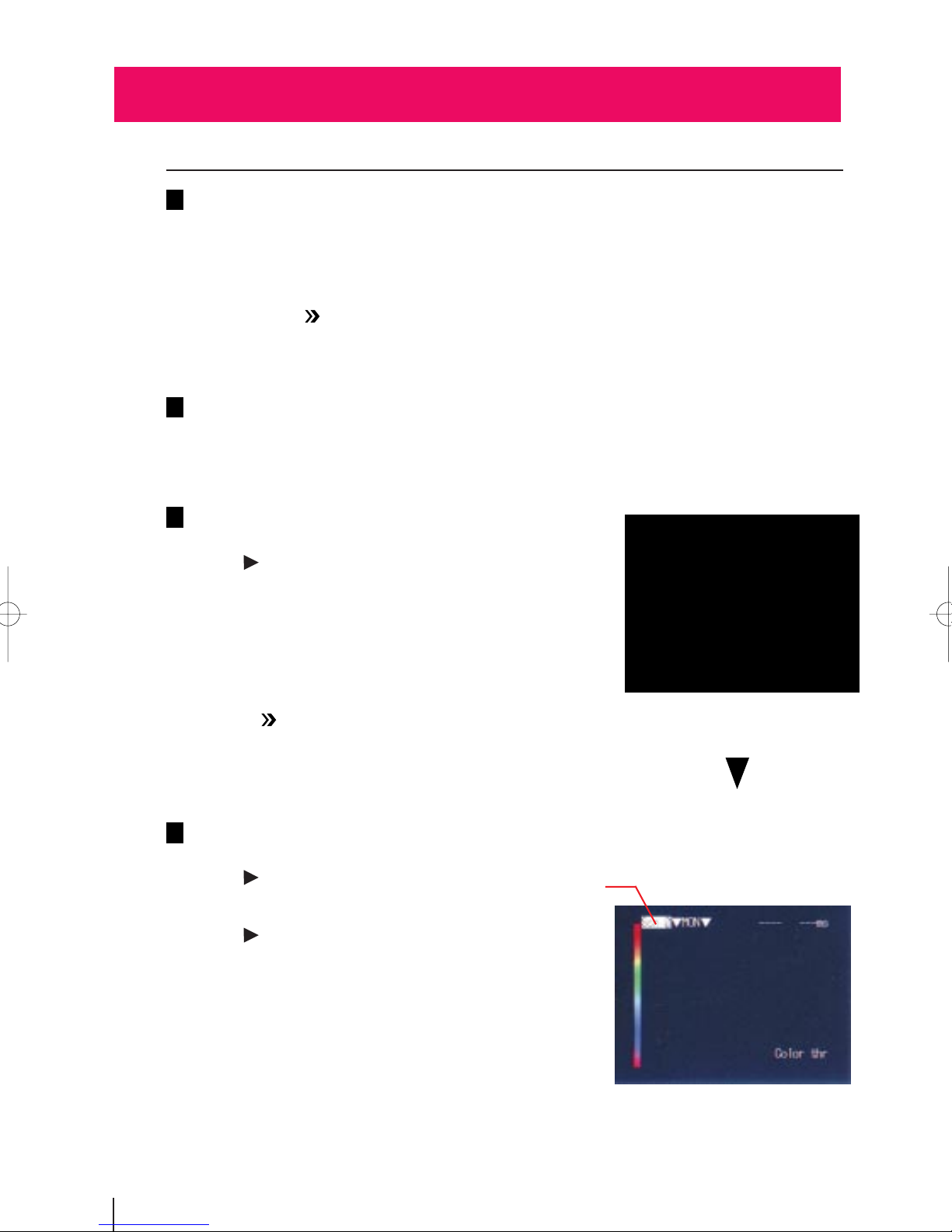
2-1-1 Starting
Be sure that the basic F400 components have been connected correctly.
1
NOTE: Read "Setup Manual" before attempting to setup or wire the F400 components.
Appendix
Turn ON the power supply on the monitor .
2
Turn ON the power supply on the F400.
3
The opening screen will appear.
See "Setup Manual" for camera setting distance and
the details of lens.
Appendix
Setup Manual "2-4 Camera"
Setup Manual "2-2 Connections", "2-3 Power Supply and Ground"
Vision Inspection System
F400-C10 Series
Color-Gray Menu Software
Ver. 2.00
(C) Copyright OMRON Corporation
1998-1999
All Rights Reserved
The image has been taken b y camera will be display ed.
4
The following screen will appear the first
time power is turned ON.
The reversed part of the display is called
cursor. Use the cursor keys to select
items.
Trouble shooting
Camera images do not appear on the screen.
*The Camera Cable is not properly connected.
*The lens cap has not been removed.
*The lens diaphragm is opened or closed too far.
12
Cursor
Page 14
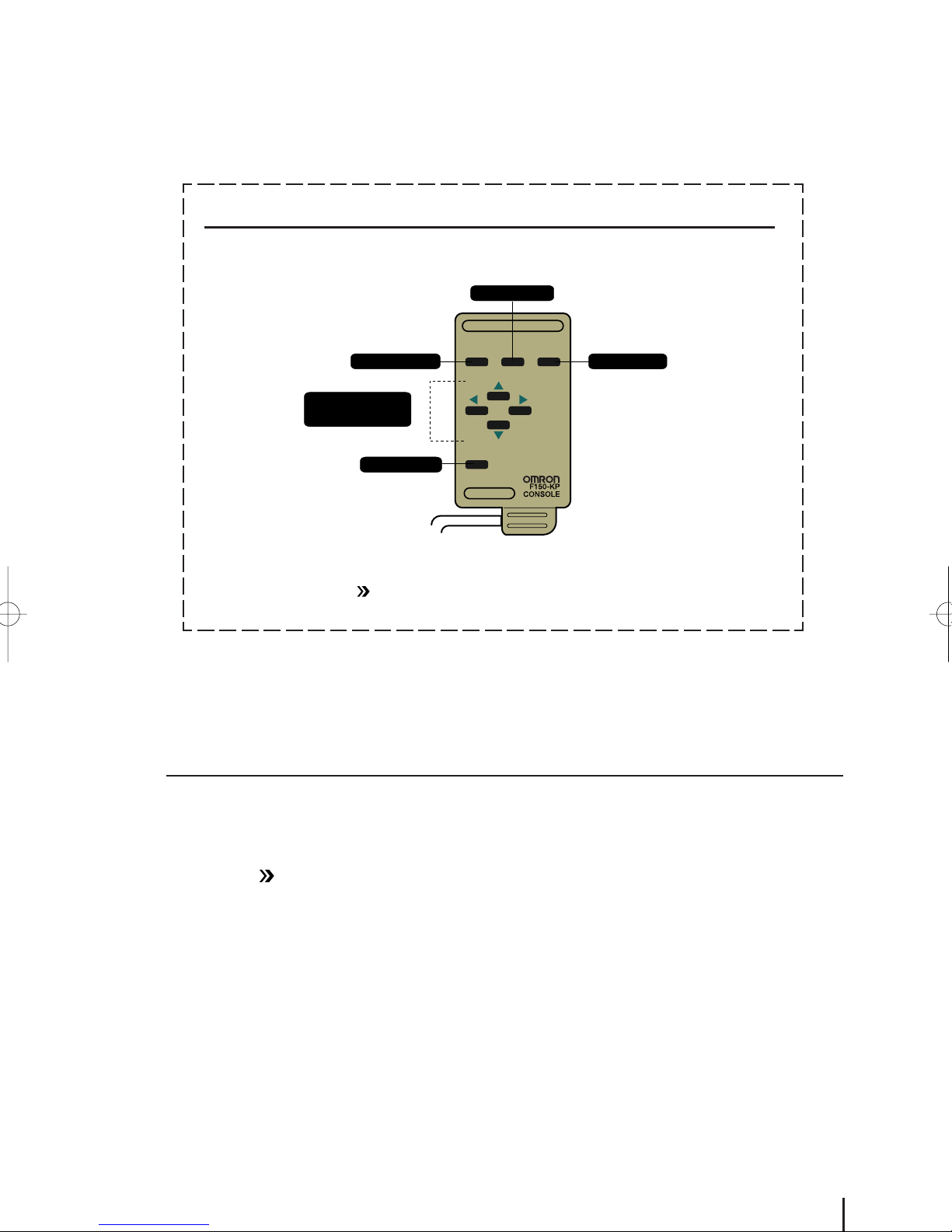
Console
The F400 is operated with selecting functions from the screen and the console is used to
perform menu operations. Be sure to familiarize yourself with console operations before
actually using the menus.
TRIGger key
2-1-2 Quitting
ESC TRIG
ESCape key
ENT
ENTer key
Up, Down, Left,
and Right keys
SHIFT key
SHIFT
Menu operations can be performed with computer via RS-232C port.
Appendix
Operation Manual "6-2 RS-232C Port"
The power can be turned OFF in any mode.
But do not turn OFF the power while saving or loading the data, and be sure to save the data
before turning OFF the power so as not to lose the data. See "Operation Manual" for saving the
setting data.
Appendix
Operation Manual "2-2-5 Quitting"
NOTE: Do not turn OFF the power while saving the measurement conditions in the following
procedure.Data in flash memory may be lost, and the F400 may not operate properly the next time
when it is started.
13
Page 15

2-2 Surface Defects on Bottle Caps
This section describes functions and setting steeps with the application of surface def ects of bottle
caps. Read this section with actual operation using the picture of measurement object at the end
of this manual.
Setting example
Camera
Extension Tube 1(mm)
Lens 25 (mm)
Camera
distance
OK
NG
320 (mm)
(acceptable) (unacceptable)
1. Change the operating mode.
2. Select the scene mode.
3. Adjust the image.
Field of vision 50(mm)
Select "SET" mode.
Select "Color filter" mode.
Select "Colorgray" for the color filter.
4. Set the measurement region.
5. Measure the objects.
14
Set the region with "surface defect".
Select "RUN" mode.
Page 16

2-2-1 Changing Operating Mode
Select "SET" mode to set measurement condition.
The following screen will be display ed when the pow er
1
is turned ON.
Use the Right Key to move the cursor to "MONitor"
2
and press the ENTer key.
Select "SET" mode
2-2 Surface Defect on Bottle Caps
Use the Up Key to move the cursor to "SET" mode
3
and press the ENTer key.
The screen enters setting mode.
After a short pause, the screen to select the scene mode will appear.
15
Page 17

2-2-2 Selecting Scene Mode
Measurement conditions, such as the type of measurement object and the contents of the inspection, are
input under "scenes". Up to 16 scenes can be set. "Color pickup mode" and "Color filter mode" are called
scene mode. One of these will be selected to inspect in each scene. Difference between "Color pickup
mode" and "Color filter mode" is described in the beginning of the book.
NOTE: Scene mode cannot be changed if scene 0 is already set.
Clear the scene or switch into another scene.
Select "Color filter" and press the ENTer key.
1
"Color filter" has been set to scene 0. After a short pause, basic screen for "SET"
mode will appear.
Clear the scene before changing the setting already registerd.
Select "Color filter" mode.
<How to clear the scene>
Press the ESCape key.
1
Leaves "SET" mode.
Select "Scene 0" and press the ENTer key.
2
A selection of 9 scenes (0 to 8) will be
displayed.
Press the SHIFT+ESCape keys at scene 0.
3
A selection of "Copy" and "Clear" will
be displayed.
Select "Clear" and press the ENTer key.
4
A confirmation message will be displayed.
5 Select "Execute" and press the ENTer key .
2
3
4
Scene data will be cleared and the display will return to the screen of .
2-2-1 Changing Operating Mode —>P.15
16
2
5
Page 18

2-2-3 Adjusting Images
The image read by camera will be processed into the image can be easily measured.
Confirming the displayed image on the monitor, process it into "Colorgray filter" to get high-contrast
between the defect and the background.
1Select "Adjust" and press the ENTer key.
2Select "Colorgray" and press the ENTer key .
Select "Colorgray" for Color filter.
2-2 Surface Defect on Bottle Caps
3 Press the ENTer key to set the color filter.
Select "Color select" and press the ENTer key .
4
The screen to set the colorgray filter
will be displayed.
17
Page 19

Use the Up and Down Keys to move the cursor parameter to
5
the color bar pointer.
The selected color will be lighted.
Adjust the position of cursor to get
highest contrast.
Press the ENTer key.
6
The screen of 4 will appear.
Press the ESCape key and the screen of
7
will appear.
1
18
Page 20

2-2-4 Setting Measurement Region
Set the measurement region in which the inspection is to be performed.
Select "Surface defect" to detect surface defect on the measurement object.
<About surface defect>
A measurement method detected by dispersion of light (density) on the object. Extremely dark or
light part of the object will be detected as defect. Degree of defect will be shown by "defect" 0 to 255.
Make output light for hue of measured color as close as registered color.
Setting of the Measurement Region
Select "Measurement region" and press the ENTer key.
1
Set the measurement region with "Surface defect".
2-2 Surface Defect on Bottle Caps
Select "0." and press the ENTer key.
2
Select "Surface defect" and press the ENTer key.
3
Select "Box" and press the ENTer key.
4
Select "Region" and press the ENTer key.
5
19
Page 21

Specify upper-left corner of the measurement region.
6
Use the cursor keys to move the cursor and press the
ENTer key.
6
Specify lower-right corner of the measurement region.
7
Use the cursor keys to move the cursor and press the
ENTer key.
The measurement region will be indicated by
dotted line on the screen.
Setting the Judgement
Select "Conditions" and press the ENTer key.
8
Change the value of defect into "30" and press the
9
ENTer key.
Change the numeral with a one-digit cursor appeared on the display.
Use the Left and Right Keys to move the
cursor to the digit to be input.
Use the Up and Down Keys to change the
numeral.
Judgement value
for displayed image.
Judgement
condition
7
9
11
<Judgement condition>
Judgement condition is set for surface defect with the model to enable checking whether or not the
model with no defect has been found. If the defect is larger than judgement condition, surface defect
may be found.
Judgement condition is set at "10" regarding defect deg ree of displayed image as criterion.
Press the ENTer key after changing the numeral.
10
Select "End" and press the ENTer key.
11
=mкЙлл=нЬЙ=bp`~йЙ=вЙу=лЙоЙк~д=нбгЙл=~еЗ=нЬЙ=лЕкЙЙе=зС=1==пбдд=~ййЙ~кK
12
(Ex.) Sample B Sample C
Defect degree 10
Sample A
Judgement
condition
40
OK
(acceptable) (unacceptable) (unacceptable)
72 168
NG NGJudgement
20
Page 22

2-2-5 Measuring Objects
Input measurement trigger and the measurement will be performed according
to the conditions set for the current scene.
The results will be output to OR terminal of the terminal block.
Press the ESCape key in following screen to leave
1
"SET" mode.
Select "MONitor" to enter "RUN" mode and press the
2
ENTer key.
Select"RUN"mode.
2-2 Surface Defect on Bottle Caps
Select "RUN" and press the ENTer key .
3
The screen enters measurement mode.
Press the TRIGger k e y.
4
One measurement will be performed.
21
Page 23

For more stable measurements
1. Additional Measurement Region
Circle cannot be measured wholly by box measurement region.
Whole object will be measured with one more measurement region.
See "Operation Manual".
Appendix
Operation Manual "3-3 Measurement Methods"
Measurement object
To measure the wholly object
Measurement
Region 0 (Box)
Measurement
Region 1
(Circumference)
Out of measurement
The measurement object will be measured wholly.
Measurement Region
0 + Measurement
Region 1
22
Page 24

2. Position Compensation
Use the position compensation function when the orientation and displacement of the measurement objects are not consistent. If the measurement object is not in a consistent position, the image read by the
camera and the measurement region will not be aligned properly and a correct judgement will not be
obtained. See "Operation Manual"
Measurement
region
Appendix
Operation Manual "3-2 Position Compensation"
WRONG OK
Scroll
the image
2-2 Surface Defect on Bottle Caps
Measurement object is out of
the screen.
The part of the measurement
region is correctly positioned
in measurement region.
"Area & gravity" will be av ailab le for this application.
Position compensation will be performed with the gravity of white pixels in measurement region. The
image must be converted (binarized) to black (0) and white (1) pix els beforehand.
Binarized image
Position
Gravity of white pixels
compensation region
23
Page 25

2-3 Ice Cream Separation
This section describes functions and setting steps with the application of ice cream separation.
Read this section with actual operation using the picture of measurement object at the end of
this manual.
OMRON
Ice Cream
Vanilla
OMRON
Ice Cream
Strawberry
Ice Cream
1. Change the operating mode.
OMRON
Lemon
Setting example
Camera
distance 370 (mm)
Field of vision 80 (mm)
Select "SET" mode.
Camera
Lens 16 (mm)
2. Select the scene mode.
3. Adjust the image.
4. Set the measurement region.
5. Set the output.
6. Check the measurement.
7. Measure the objects.
Select "Color pickup".
Register the color to be picked up.
Set the region with "Area & gravity".
Select "Judge".
Select "MONitor" mode.
Select "RUN" mode.
24
Page 26

2-3-1 Changing Operating Mode
Select "SET" mode to set measurement condition.
The following screen will be displa y ed after the po wer is
1
turned ON.
Use the Right Key to move the cursor to "MONitor" and
2
press the ENTer key.
Select "SET" mode.
OMRON
Ice Cream
OMRON
Ice Cream
Strawberry
Vanilla
OMRON
Ice Cream
Lemon
Select "SET" and press the ENTer key.
3
The screen enters setting mode.
After a short pause, the screen to select the scene mode will appear.
2-3 Ice Cream Separation
25
Page 27

2-3-2 Selecting Scene Mode
Measurement conditions, such as the type of measurement object and the contents of the inspection,
are input under "scenes". Up to 16 scenes can be set. "Color pickup mode" and "Color filter mode" are
called scene mode. One of these will be selected to inspect in each scene . Difference between "Color
pickup mode" and "Color filter mode" is described in the beginning of the book.
NOTE: Scene mode cannot be changed if scene 0 is already set.
Clear the scene or switch into another scene.
Select "Color pickup" and press the ENTer key.
1
"Color pickup" has been set to scene 0.
After a short pause, basic screen for "Set"
mode will appear.
Clear the scene before changing the setting already registered.
Select "Color pickup" mode.
<How to Clear the Scene>
Press the ESCape key.
1
Leaves "SET" mode.
Select "Scene 0" and press the ENTer key.
2
A selection of 9 scenes (0 to 8) will be
displayed.
Press the SHIFT+ESCape keys at scene 0.
3
A selection of "Copy" and "Clear" will
be displayed.
Select "Clear" and press the ENTer key.
4
A confirmation message will be displayed.
Select "Execute" and press the ENTer key.
5
2
3
4
Scene data will be cleared and the display will return to the screen of .
2-3-1 Changing Operating Mode —>P.25
26
2
5
Page 28

2-3-3 Adjusting Images
Register the color to be picked up.
Confirming the displayed image on the monitor , register the colors (three colors) of ice cream lid in
"Pickup color ".
Select "Adjust" and press the ENTer key.
1
Select "Pickup color" and press the ENTer key.
2
Registering screen of pickup color 0 will
be displayed.
OMRON
Ice Cream
OMRON
Ice Cream
Strawberry
Vanilla
OMRON
Ice Cream
Lemon
3
Press the ENTer key to register the color of "V anilla" in
"Pickup color 0".
Use the Left and Right Keys to switch the
picked up color number can be switched.
Other colors will be registered for picked
up color 1 to 2. Picked up color 1: Register the color of "strawberry". Picked up
color 2: Register the color of "lemon".
Use the cursor keys to move the box to the color to be
4
picked up.
Press the SHIFT+ENTer keys to change
the size of box on the screen.
Press the TRIGger k e y.
5
Color to be picked up will be displayed.
Repeat above steps
to 5 to make the
4
color to be picked up to be wholly displayed.
2-3 Ice Cream Separation
27
Page 29

Press the ENTer key.
6
The color inside the box will be registered
and the screen of
Use the Right Key to switch the pickup color number.
7
Register other colors repeating above steps
to 6.
3
Press the ESCape key several times and the
8
screen of
will appear.
1
will appear.
3
28
Page 30

2-3-4 Setting Measurement Region
Set the measurement region with "Area & gravity".
Set the measurement region in which the inspection is to be performed.
Set three measurement regions with "Area & gravity" which can be measured the area of the measurement object.
<Area & gravity >
The pixels of picked up color will be counted in the measurement region. The counted pixels are called
"Area". Set the box of the same size at the same position in the measurement region 0 to 2. (Set the
measurement region in space of no letter.) Counted area can tell the color being measured.
Measurement region 0
(Color pickup 0)
OMRON
Ice Cream
Vanilla
The area will be counted
only when "vanilla" ice
creams are under measured.
1
Select "Measurement region" and
press the ENTer key.
The table of measurement region number will be displayed.
Measurement region 1
(Color pickup 1)
Measurement region
The area will be counted
only when "strawberry"
ice creams are under
measured.
OMRON
Ice Cream
Strawberry
Measurement region 2
(Color pickup 2)
Measurement region
Ice Cream
The area will be counted
only when "lemon" ice
creams are under measured.
OMRON
Lemon
OMRON
Ice Cream
OMRON
Ice Cream
Strawberry
Vanilla
OMRON
Ice Cream
Lemon
Select "0." and press the ENTer key.
2
Select "Area & gravity" and press the ENTer key.
3
2-3 Ice Cream Separation
29
Page 31

Selecting color to be picked up
Select "Color no." and press the ENTer key.
4
Use the Left and Right Keys to select color to be picked
5
up, and press the ENTer key.
Pickup color 0 will be selected for the
measurement region 0.
Setting the Region
Select "Region" and press the ENTer key.
6
Select "New" and press the ENTer key.
7
Select "Box" and press the ENTer key.
8
Select "OR" and press the ENTer key.
9
"OR" is for setting the region, "NO T" is for
partly erasure.
30
Page 32

Specify upper-left corner of the measurement region. Use
10
the cursor keys to mov e the cursor and press the ENTer key .
Specify lower-right corner of the measurement region.
11
Use the cursor keys to move the cursor and press the
ENTer key.
The measurement region will be indicated by
dotted line on the screen.
Press the ESCape key se veral times and the
12
screen of
will appear.
2
10
11
Select "1." and press the ENTer key.
13
Repeat above steps
to 12 and set the
3
measurement region 1 to 2.
Press the ESCape key several times and the screen
14
of
will appear.
1
OMRON
Ice Cream
Vanilla
OMRON
Ice Cream
Lemon
OMRON
Ice Cream
Strawberry
2-3 Ice Cream Separation
31
Page 33

2-3-5 Setting Output
Select "Judge".
Set the output for external device.
Set so as to the results of measurement region 0 to 2 will be output to the terminal block DO_0 to 2. The
color will be inspected depending on the region of OK (acceptable) result.
<Setting Judgement Condition>
Judgement condition is set for measuring the area of color pick up and of no pic k ed up color. Refer to
the measurement for the displayed image. The picked up color in the measurement region of OK
result will be under inspection.
(Ex.) Yellow (lemon) is under inspection.
Measurement region 0
(DO_0)
Area=8
Measurement region Measurement region
Measurement region 1
(DO_1)
Area=3
Measurement region 2
(DO_2)
Area=3720
OMRON
Ice Cream
Lemon
Judgement
NG NG OK
(unacceptable) (unacceptable) (acceptable)
For counting the area may be influenced by noise, set the value a little higher.
pЙдЙЕн=?bсйкЙллбзе?=~еЗ=йкЙлл=нЬЙ=bkqЙк=вЙуK
1
pЙдЙЕн=?gмЗЦЙ?=~еЗ=йкЙлл=нЬЙ=bkqЙк=вЙуK
2
pЙдЙЕн=?MK?=~еЗ=йкЙлл=нЬЙ=bkqЙк=вЙуK
3
"0." indicates DO_0 of terminal block.
32
Page 34

pЙдЙЕн=x===z=~еЗ=йкЙлл=нЬЙ=bkqЙк=вЙуK
4
pЙдЙЕн=?oM?=~еЗ=йкЙлл=нЬЙ=bkqЙк=вЙуK
5
"R0" indicates measurement region 0.
pЙдЙЕн=?^кЙ~=j^?=~еЗ=йкЙлл=нЬЙ=bkqЙк=вЙуK
6
R0.MA will be set.
pЙдЙЕн=?lh?=~еЗ=йкЙлл=нЬЙ=bkqЙк=вЙуK
7
OMRON
Ice Cream
Vanilla
OMRON
Ice Cream
Lemon
OMRON
Ice Cream
Strawberry
2-3 Ice Cream Separation
Operational expression will be set.
Then set the judgement condition.
33
Page 35

Select "Upper" and press the ENTer key.Then change
8
the numeral by digits.
8
See p.32 to set the judgement condition.
Change the numeral with a one-digit cursor appeared on the display.
Use the Left and Right Keys to move the
cursor to the digit to be input.
Use the Up and Down Keys to change the
numeral.
Press the ENTer key, after changing the numeral.
9
Select "Lower" and press the ENTer key.
10
Press the ESCape key and the screen of 3 will
11
appear.
First 8 letters of expression that had been
set will be displayed.
Select "1." and press the ENTer key.
12
10
Repeat the steps 4 to 11, set "1." to
"R1.MA" and set "2." to "R2.MA".
Press the ESCape key sev er al times and the
13
screen of
will appear.
1
34
Page 36

2-3-6 Checking Measurements
Select "MONitor" mode.
With practical operation, check that the measurement would be performed correctly with
the conditions already set. The results will be just displayed on the screen. Not be output
to the terminal block. Measurement condition can be adjusted referring to the judgement.
Press the ESCape key in following screen to leave
1
"SET" mode.
Operation will be in monitor mode auto-
matically.
Press the SHIFT+ESCape keys, to confirm out-
2
put result in terminal block, to confirm output
result in terminal block.
Select "Display result: None" and press the ENTer key .
3
OMRON
Ice Cream
Vanilla
OMRON
Ice Cream
Lemon
OMRON
Ice Cream
Strawberry
2-3 Ice Cream Separation
Select "All judges" and press the ENTer key.
4
35
Page 37

Select "End" and press the ENTer key.
5
Press the TRIGger k e y.
6
Results of DO_0 to 2 will be displayed.
Ice
Terminal
block
DO_0
DO_1
DO_2
Vanilla
OK
NG
NG
Strawberry
Lemon
NG
OK
NG
NG
NG
OK
"Refer to "Operation Manual - 4-1 Checking Measurements"
36
Page 38

2-3-7 Measuring Objects
Input measurement trigger and the measurement will be performed according to the conditions set for the current scene.
The results will be output to terminal block DO_0 to 2.
Select "MONitor" to enter "RUN" mode and press
1
the ENTer key.
Select "RUN" and press the ENTer key.
2
The screen enters measurement mode.
Select "RUN" mode.
OMRON
Ice Cream
OMRON
Ice Cream
Strawberry
Vanilla
OMRON
Ice Cream
Lemon
Press the TRIGger ke y.
3
One measurement will be performed.
Terminal
block
DO_0
DO_1
DO_2
Ice
Vanilla
OK
NG
NG
Strawberry
Lemon
NG
OK
NG
NG
NG
OK
2-3 Ice Cream Separation
37
Page 39

Memo
38
Page 40

SECTION 3
Appendix - Peculiarity of color -
39
Page 41

Color is expressed by hue, saturation and value.
Saturation
(Chroma)
The degree of the vividness of color
Low : Monotone color
High : Close to pure color
Value
(Lightness)
The degree of light and the
shade of color
`çäçê=`ìÄÉ
Color Pickup Mode
Hue
The color attributes such
as red, blue, and green
In color pickup mode, color image will be converted into binary image by three parameters - hue, saturation and value.
Specifying picked up color, its corresponding part of the space in color cube will be converted into "1", and the other "0".
Monotone color that cannot be treated by color gray filter, can be e xtracted in color pickup mode.
The picked up color will be
converted into "1".
The part of "1" will be
displayed by picked up
color in F400.
The colors excluding picked up
color will be converted into "0".
The part of "0" is displayed by
black at default, but it can be
converted into 5 colors "from
black to white".
40
Page 42

Colorgray filter in color filter mode
In colorgray filter, color image will be converted into gray image using hue and saturation, but lightness isn't
considered during conversion.
The density of gray image after conversion depends on the point on hue/ saturation plane of color image.
Low
Hue
High
Hue/saturation plane
Saturation
Density of colorgray image
= Saturation of measured color - (Hue of registered color - Hue of measured color)
(Ex.) Registered color: blue
Registered color
Blue
Light blue
Red
Select registered color out of 256 hues. Color bar displayed left side of a screen indicates hue.
Highest chroma colors in each hue are lined up on the color bar.
So blue must be selected on the color bar when light blue is to be registered.
As measured color is as close as registered color
and high chroma, it will be white in gray image.
Though hue is registered color, it will be gray in
gray image because of low saturation.
As measured color is as far as registered color, it
will be black in gray image though high
saturation.
See next page for the setting of color g r ay filter.
41
Page 43

1
2
How to set of colorgray filter
3
(Hue: STEP 1 to 2, Saturation: STEP 3)
Step
Step
Selecting the Registered Color
Select a color to be expressed brightly in gra y image .
"Hue of registered color - Hue of measured color" will be converted to 256 lev els in gr ay image.
Make output dark for hue of measured color as f ar as registered color.
Registered color
Low
Converting the color bar into color
circle will make it easy to understand.
High High
Low
Hue of registered color
- Hue of measured color
Switching the Color Band
HLJNUM=ЗЙЦкЙЙл
Centering the registered color, convert
the colors of +/-180 degrees into gray
image of 256 gradations.
Registered color (255)
Centering the registered color , convert the colors of
+/-90 degrees into gray image of 256 gradations.
Other colors will be converted into black.
+/- 90 degrees
Registered color (255)
Step
(0)
(0)
Adjusting the Range of Chroma
Chroma means the vividness of color. Color of lower tone will be converted into darker.
Higher tone than upper limit of the range will be white.
High
Chroma
Low
Lower tone than lower limit will be black.
Monotone
Upper limit
Gray image of 256 gradations
Lower limit
(0)
42
Page 44

43
Page 45

OMRON Corporation
Industrial Automation Company
Advanced Sensors Division
Sensing Devices and Components Division H.Q.
28th Fl., Crystal Tower Bldg.,
1-2-27, Shiromi, Chuo-ku,
Osaka 540-6028 Japan
Tel: (81)6-6949-6105/Fax: (81)6-6949-6149
Regional Headquarters
OMRON EUROPE B.V.
Wegalaan 67-69, NL-2132 JD Hoofddorp
The Netherlands
Tel: (31)2356-81-300/Fax: (31)2356-81-388
OMRON ELECTRONICS, INC.
1 East Commerce Drive, Schaumburg, IL 60173
U.S.A.
Tel: (1)847-843-7900/Fax: (1)847-843-8568
OMRON ASIA PACIFIC PTE. LTD.
83 Clemenceau Avenue,
#11-01, UE Square,
Singapore 239920
Tel: (65)835-3011/Fax: (65)835-2711
OMRON (CHINA) CO. LTD.
21F, Beijing East Ocean Center
No. 24A Jian Guo Men Wai Da Jie
Chao Yang District, Beijing, 100022
China
Tel: (86)10-6515-5778/Fax: (86)10-6515-5810
Page 46

 Loading...