

Page 1

Cat. No. Z135–E1-1
F400
Color Vision Sensor
OPERATION MANUAL
Page 2

F400 Color Vision Sensor
Operation Manual
Produced June 1999
i
Page 3

Notice:
OMRON products are manufactured for use according to proper procedures by a qualified
operator and only for the purposes described in this manual.
The following conventions are used to indicate and classify precautions in this manual.
Always heed the information provided with them. Failure to heed precautions can result in
injury to people or damage to property .
DANGER Indicates an imminently hazardous situation which, if not avoided, will result in death or
!
serious injury.
WARNING Indicates a potentially hazardous situation which, if not avoided, could result in death or
!
serious injury.
Caution Indicates a potentially hazardous situation which, if not avoided, may result in minor
!
or moderate injury , or property damage.
Visual Aids
The following headings will help you locate different types of information.
Note Indicates information of particular interest for efficient and convenient operation of the
product.
OMRON, 1999
All rights reserved. No part of this publication may be reproduced, stored in a retrieval system, or
transmitted, in any form, or by any means, mechanical, electronic, photocopying, recording, or
otherwise, without the prior written permission of OMRON.
No patent liability is assumed with respect to the use of the information contained herein. Moreover, because OMRON is constantly striving to improve its high-quality products, the information
contained in this manual is subject to change without notice. Every precaution has been taken in
the preparation of this manual. Nevertheless, OMRON assumes no responsibility for errors or
omissions. Neither is any liability assumed for damages resulting from the use of the information
contained in this publication.
Indicates pages where additional information can be found.
1. Indicates a procedure. The step numbers in the procedure correspond to the
numbers in any related illustrations.
ii
Page 4
About this Manual:
This manual describes the measurement conditions, settings, and external device communications methods for the F400 Color Vision Sensor. The F400 can take measurements using color information.
The F400 supports two scene modes that can be used for measurement: Color Pickup Mode and Color
Filter Mode. The features of these two scene modes are as follows:
Color Pickup Mode: Only the specified color is extracted and measured.
Color Filter Mode: A color filter is applied to create an easily measurable image. Color combinations
Please read this manual and other related manuals carefully and be sure to understand the information
provided before attempting to install or operate the F400. The manuals for the F400 are outlined in the following table.
Manual
Introduction
Manual
Setup
Manual
Operation
Manual
Section 1 Introduction
that are hard to distinguish in gray images because of low contrast in brightness,
such as green and yellow, can be recognized and measured.
Contents Cat. No.
Provides introductory information about the F400. This manual is
designed for first-time users of the F400 and describes features of
color gray measurement, basic operations of the F400, and the
main F400 applications.
Describes hardware, wiring, and connections required to install the
F400.
Describes F400 functions. Explains measurement settings and
methods for communications with external devices.
Z131-E1-1
Z130-E1-1
Z135-E1-1
describes features, measurement modes, and menu tree of the F400
Color Vision Sensor.
Section 2 Basic Operations
describes the overall flow of F400 application and basic opera-
tions.
Section 3 Settings
Section 4 Checking and Executing Measurements
describes how to set measurement conditions for F400 visual inspections.
describes how to monitor if correct measurements are being performed with the set measurement conditions. It also describes how to
perform measurements.
Section 5 System Settings
Section 6 Communications with External Devices
describes the system setting procedures for the F400.
describes the communications settings
and I/O formats for communications with external devices.
Section 7 Troubleshooting
lists the errors that may occur during F400 operation, along with
their probable causes and remedies.
WARNING Failure to read and understand the information provided in this manual may
!
result in personal injury or death, damage to the product, or product failure.
Please read each section in its entirety and be sure you understand the
information provided in the section and related sections before attempting
any of the procedures or operations given.
iii
Page 5

TABLE OF CONTENTS
PRECAUTIONS vii. . . . . . . . . . . . . . . . . . . . . . . . . . . . . . .
1 Safety Precautions viii. . . . . . . . . . . . . . . . . . . . . . . . . . . . .
2 General Precautions viii. . . . . . . . . . . . . . . . . . . . . . . . . . .
SECTION 1 – Introduction 1. . . . . . . . . . . . . . . . . . . . . . .
1-1 Features 2. . . . . . . . . . . . . . . . . . . . . . . . . . . . . . . . . . . . .
1-2 Measurement Modes 4. . . . . . . . . . . . . . . . . . . . . . . . . . .
1-2-1 Color Pickup and Color Filter Modes 4. . . . . . . . . . . . .
1-2-2 Additional Color Filter Mode 4. . . . . . . . . . . . . . . . . . .
1-3 Menu Trees 5. . . . . . . . . . . . . . . . . . . . . . . . . . . . . . . . . .
SECTION 2 – Basic Operations 7. . . . . . . . . . . . . . . . . . .
2-1 Menu Operations 8. . . . . . . . . . . . . . . . . . . . . . . . . . . . . .
2-1-1 Screen Displays 8. . . . . . . . . . . . . . . . . . . . . . . . . . . . . .
2-1-2 Input Devices 8. . . . . . . . . . . . . . . . . . . . . . . . . . . . . . . .
2-1-3 Menu Tree 10. . . . . . . . . . . . . . . . . . . . . . . . . . . . . . . . . .
2-1-4 Inputting Values 10. . . . . . . . . . . . . . . . . . . . . . . . . . . . . .
2-1-5 Drawing Measurement Regions 12. . . . . . . . . . . . . . . . . .
2-2 Starting and Quitting 14. . . . . . . . . . . . . . . . . . . . . . . . . . .
2-2-1 Starting 14. . . . . . . . . . . . . . . . . . . . . . . . . . . . . . . . . . . .
2-2-2 Selecting Scene Modes 15. . . . . . . . . . . . . . . . . . . . . . . .
2-2-3 Changing Scenes 16. . . . . . . . . . . . . . . . . . . . . . . . . . . . .
2-2-4 Copying and Clearing Scenes 17. . . . . . . . . . . . . . . . . . .
2-2-5 Quitting 18. . . . . . . . . . . . . . . . . . . . . . . . . . . . . . . . . . . .
SECTION 3 – Settings 21. . . . . . . . . . . . . . . . . . . . . . . . . . .
3-1 Adjusting Images 22. . . . . . . . . . . . . . . . . . . . . . . . . . . . . .
3-1-1 Shutter Speed 24. . . . . . . . . . . . . . . . . . . . . . . . . . . . . . . .
3-1-2 Applying Color Filters 24. . . . . . . . . . . . . . . . . . . . . . . . .
3-1-3 Creating a Color Filter 26. . . . . . . . . . . . . . . . . . . . . . . . .
3-1-4 Picking Up Measurement Colors 28. . . . . . . . . . . . . . . . .
3-1-5 Filtering 33. . . . . . . . . . . . . . . . . . . . . . . . . . . . . . . . . . . .
3-1-6 Background Suppression 34. . . . . . . . . . . . . . . . . . . . . . .
3-1-7 Output Calibration 36. . . . . . . . . . . . . . . . . . . . . . . . . . . .
3-2 Position Compensation 37. . . . . . . . . . . . . . . . . . . . . . . . .
3-2-1 Adjusting Images for Easier Position Compensation 38. .
3-2-2 Setting Position Compensation Regions 38. . . . . . . . . . .
3-2-3 Searches 40. . . . . . . . . . . . . . . . . . . . . . . . . . . . . . . . . . . .
3-2-4 Position Compensation using Edges 43. . . . . . . . . . . . . .
3-2-5 Area and Center of Gravity, and Center of
Gravity and Axis Angle 46. . . . . . . . . . . . . . . . . . . . . . . .
3-3 Measurement Methods 50. . . . . . . . . . . . . . . . . . . . . . . . .
3-3-1 Measurement Regions 50. . . . . . . . . . . . . . . . . . . . . . . . .
v
Page 6

Table of contents
3-3-2 Surface Defects 52. . . . . . . . . . . . . . . . . . . . . . . . . . . . . .
3-3-3 Searches 55. . . . . . . . . . . . . . . . . . . . . . . . . . . . . . . . . . . .
3-3-4 Edge Processing 63. . . . . . . . . . . . . . . . . . . . . . . . . . . . .
3-3-5 Area and Center of Gravity, and Center of
Gravity and Axis Angle 67. . . . . . . . . . . . . . . . . . . . . . . .
3-4 Expressions 75. . . . . . . . . . . . . . . . . . . . . . . . . . . . . . . . . .
SECTION 4 – Checking and Executing Measurements 83
4-1 Checking Measurements 84. . . . . . . . . . . . . . . . . . . . . . . .
4-1-1 Adjusting Evaluation Criteria while
Viewing Measurements 85. . . . . . . . . . . . . . . . . . . . . . . .
4-2 Measuring 92. . . . . . . . . . . . . . . . . . . . . . . . . . . . . . . . . . .
4-2-1 Adjusting Evaluation Criteria during Measurement 93. . .
SECTION 5 – System Settings 95. . . . . . . . . . . . . . . . . . . .
5-1 White Balance 96. . . . . . . . . . . . . . . . . . . . . . . . . . . . . . . .
5-2 Output Destination 97. . . . . . . . . . . . . . . . . . . . . . . . . . . .
5-3 Backup 97. . . . . . . . . . . . . . . . . . . . . . . . . . . . . . . . . . . . . .
5-3-1 Operations Using the F400 97. . . . . . . . . . . . . . . . . . . . .
5-3-2 Operation Examples for the Personal Computer 99. . . . .
5-4 Display Settings 100. . . . . . . . . . . . . . . . . . . . . . . . . . . . . . .
5-4-1 Measurement Screen Settings 100. . . . . . . . . . . . . . . . . . .
5-4-2 Changing the Display Image 103. . . . . . . . . . . . . . . . . . . .
5-5 Key Allocation 106. . . . . . . . . . . . . . . . . . . . . . . . . . . . . . .
5-6 Startup Mode 107. . . . . . . . . . . . . . . . . . . . . . . . . . . . . . . . .
5-7 Error Settings 108. . . . . . . . . . . . . . . . . . . . . . . . . . . . . . . . .
5-8 Version 110. . . . . . . . . . . . . . . . . . . . . . . . . . . . . . . . . . . . . .
SECTION 6 – Communications with External Devices 111
6-1 Terminal Blocks 112. . . . . . . . . . . . . . . . . . . . . . . . . . . . . .
6-1-1 I/O Format 112. . . . . . . . . . . . . . . . . . . . . . . . . . . . . . . . . .
6-1-2 Terminal Signal Operation and Timing 112. . . . . . . . . . . .
6-1-3 Setting Communications (T erminal Block) 118. . . . . . . . .
6-2 RS-232C Port 119. . . . . . . . . . . . . . . . . . . . . . . . . . . . . . . .
6-2-1 Flowcharts 119. . . . . . . . . . . . . . . . . . . . . . . . . . . . . . . . . .
6-2-2 Setting Communications (RS-232C) 121. . . . . . . . . . . . . .
6-2-3 Input Command List 122. . . . . . . . . . . . . . . . . . . . . . . . . .
6-2-4 I/O Format 123. . . . . . . . . . . . . . . . . . . . . . . . . . . . . . . . . .
SECTION 7 – Troubleshooting 135. . . . . . . . . . . . . . . . . . . .
Glossary 139. . . . . . . . . . . . . . . . . . . . . . . . . . . . . . . . . . . . . .
Index 149. . . . . . . . . . . . . . . . . . . . . . . . . . . . . . . . . . . . . . . . .
vi
Page 7

PRECAUTIONS
This section provides general precautions for using the F400 Color Vision Sensor.
The information contained in this section is important for the safe and reliable application of the F400 Color
Vision Sensor. You must read this section and understand the information contained before attempting to
set up or operate a F400 Color Vision Sensor.
1 Safety Precautions viii. . . . . . . . . . . . . . . . . . . . . . . . . . . . .
2 General Precautions viii. . . . . . . . . . . . . . . . . . . . . . . . . . .
vii
Page 8
PRECAUTIONS
1 Safety Precautions
WARNING Cover the terminal blocks with the Terminal Block Protection Covers.
!
Uncovered terminal blocks can result in electric shock.
WARNING Use DC power supplies with safe extra low-voltage circuits on the
!
secondary side for the main F400 power supply and power supplies for
the terminal blocks. Excessively high voltages can result in electric
shock.
Caution Do not touch fluorescent or halogen lights while the power is ON or
!
immediately after the power is turned OFF. These lights generate heat
and can cause burns.
Caution Do not use the F400 in environments with flammable or explosive gases.
!
Caution Install the F400 away from high-voltage equipment or motors to ensure safety during
!
operation and maintenance.
Caution Use the power supply cables and crimp terminals of specified sizes.
!
Caution Use at the power supply voltages specified in this manual.
!
Caution Be sure to securely tighten the screws when mounting F400 components.
!
Caution Do not dismantle, repair or modify any F400 components.
!
Caution Dispose of F400 components as industrial waste.
!
Caution To prevent damage from static electricity, use a wrist strap or another device for pre-
!
venting electrostatic charges when touching terminals or connector signal lines.
Caution Do not turn OFF the power while a message is being displayed indicating that proces-
!
sing is being performed. Data in memory will be destroyed, and the F400 may not
operate correctly the next time it is started.
2 General Precautions
The user must operate the product according to the performance specifications
described in the operation manuals.
Before using the product under conditions which are not described in the manual or
applying the product to nuclear control systems, railroad systems, aviation systems,
vehicles, combustion systems, medical equipment, amusement machines, safety
equipment, and other systems, machines, and equipment that may have a serious
influence on lives and property if used improperly, consult your OMRON representative.
Make sure that the ratings and performance characteristics of the product are sufficient for the systems, machines, and equipment, and be sure to provide the systems,
machines, and equipment with double safety mechanisms.
viii
Page 9

SECTION 1
Introduction
This section describes features, measurement modes, and menu tree of the F400 Color Vision Sensor.
1-1 Features 2. . . . . . . . . . . . . . . . . . . . . . . . . . . . . . . . . . . . .
1-2 Measurement Modes 4. . . . . . . . . . . . . . . . . . . . . . . . . . .
1-2-1 Color Pickup and Color Filter Modes 4. . . . . . . . . . . . .
1-2-2 Additional Color Filter Mode 4. . . . . . . . . . . . . . . . . . .
1-3 Menu Trees 5. . . . . . . . . . . . . . . . . . . . . . . . . . . . . . . . . .
1
Page 10

1-1 Features
Color Images
Color information from a color image can be used when performing measurements.
Select one of the two F400 measurement modes, called scene modes, depending on
the application. The two modes are Color Pickup Mode and Color Filter Mode.
Refer to t h e
and applications.
Color Pickup Mode
The Color Pickup mode is used to extract only specified colors. Simply click the color
to be displayed on the screen to register it as a pickup color. Up to 8 colors can be
registered per scene.
Applications include separation by color, such as for ice cream separation or for wiring checks.
Color Filter Mode
A color filter can be applied to create an easily measurable image. There are five color
filters: Red, green, blue, colorgray , and gray. The colorgray filter is used to convert a
color image to a grayscale image with 256 gradations by using hue and saturation
settings. The colorgray filter enables measurement of color combinations, such as
green and yellow, with low contrast in brightness making them hard to distinguish in
gray images.
Applications include detection of small defects, such as surface defects on bottle
caps, and inspection free from background distortion, such as inspecting the amount
of adhesive that has been coated on a surface.
Introduction Manual (Z131)
1-1SectionFeatures
for information on color (hues and saturation)
2
Page 11
1-1SectionFeatures
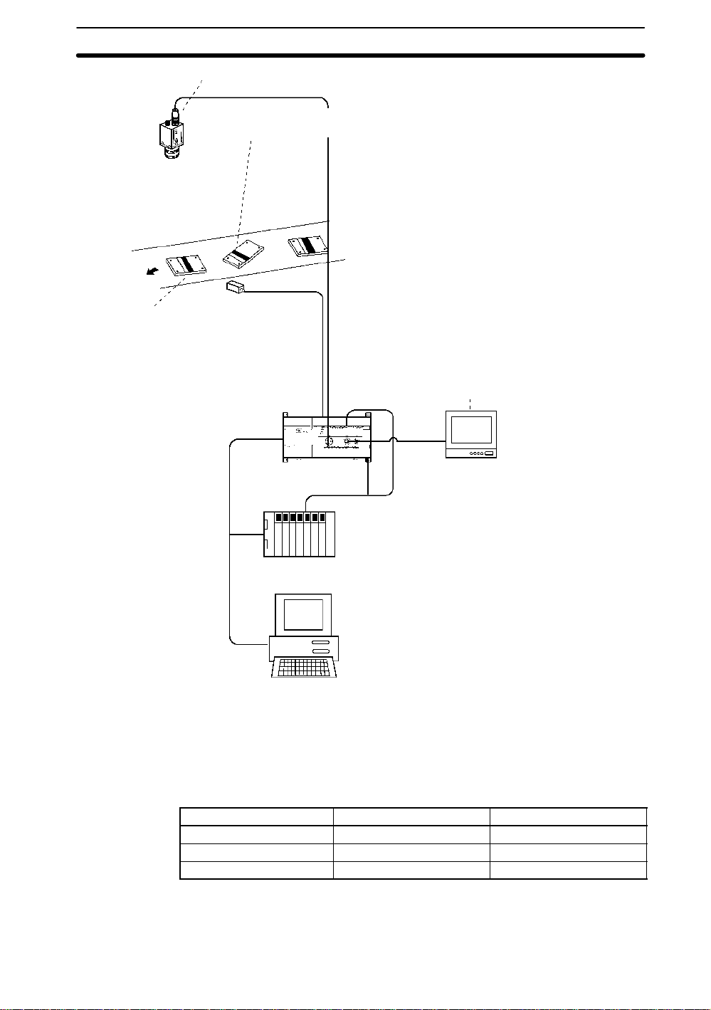
• Shutter speed can be adjusted to speed of measurement object.
• Position and orientation of object can be compensated before measurement. → p. 37
There are four methods: Using search, edge, area and center of gravity, or center of gravity
Camera
• Setup can be changed smoothly.
→ p. 16 Each of 16 scenes can be
set up for different inspection
conditions. Change scenes to
setup a different measurement
object.
and axis angle.
Sync sensor
• Color of object and color read by camera can be adjusted automatically using white balance.
time lighting is changed.
• Camera image can be adjusted to facilitate measurement.
Filtering: Edges of object are enhanced and noise reduced.
33
Background suppression: Background of object, such as pat-
terns, is excluded from measurement.
Color filter: Contrast of measurement area is increased
• Up to 8 specified colors can be picked up.
• Images can be checked on screen. Up to 16 images can be stored
in memory to confirm past images to see what problems have
occurred. Images can be backed up on a computer.
F400
→ p. 24
→ p. 96 Adjust white balance each
→ p.
→ p. 34
→ p.24
→ p. 28
→ p. 100
Monitor
Programmable Controller
• Communications with external devices is possible through a
terminal block or RS-232C port. Refer to the table on the next
page.
•The distance between two regions or the maximum value
Personal computer
can be obtained by calculating measured values or by
using functions.
→ p. 75
Input/Output Terminal block RS-232C
Trigger input Yes Yes
Measurement values output No Yes
Judgement output (OK/NG) Yes No
Terminal blocks:
RS-232C port:
→ p. 112
→ p. 119
3
Page 12

1-2 Measurement Modes
There are five measurement modes. Different modes are available depending on the
scene mode.
1-2-1 Color Pickup and Color Filter Modes
Search → p. 55, 144
Density searches are used when inspecting the shape of specific objects. The object
is measured using a registered measurement pattern called a model. The position of
the object and the degree of conformity, called the correlation, with the model are calculated.
Edge
→ p. 63, 140
The edge measurements are used to find the coordinates of edges of the measurement object. The width of an object can be calculated by using an equation to subtract
edge coordinates.
Area and Center of Gravity
The binary center of gravity and area can be used to calculate the size (i.e., the area)
and the position (i.e., the center of gravity) of the measurement object.
Center of Gravity and Axis Angle
The binary axis angle can be used to calculate the orientation (i.e., the binary axis) of
the measurement object, in addition to the center of gravity and area. Binary axis
searches increase processing time, so binary center of gravity and area searches
should be used when only the center of gravity and area are required.
→ p. 67, 147
→ p. 67, 147
1-2SectionMeasurement Modes
1-2-2 Additional Color Filter Mode
Surface Defects → p. 52, 142
The measurement object can be inspected for surface defects. Areas that are largely
different in densities are detected as defects.
4
Page 13
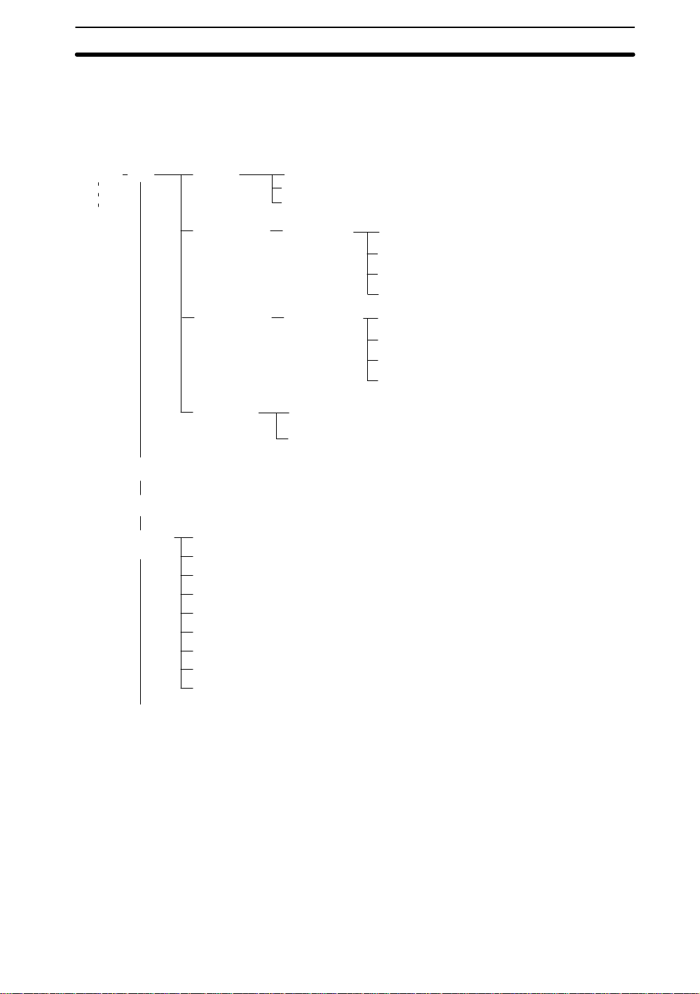
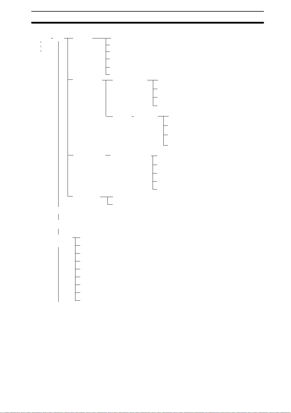
1-3 Menu Trees
Color Pickup and Color Filter Modes have different menu hierarchies. The menu hierarchies are outlined in the following diagrams. The same hierarchy exists under each
scene.
Color Pickup
Scene 0
Scene 15
→ p. 16
SET
Adjust
Position
compensation
Shutter speed → p. 24
Pickup color
Calibration
Region 0
Region 1
→ p. 28
→ p. 36
Area & gravity
Gravity & axis → p. 46
Edge → p. 43
Search → p. 40
1-3SectionMenu Trees
→ p. 46
Measurement
region
Expression
MON (Monitor) → p. 84
→ p. 92
RUN
SYS
(System)
SAVE → p. 18
White balance → p. 96
Communications settings→ p. 118, 121
Output → p. 97
Backup → p. 97
Display settings → p. 100
Set key operation
Startup mode → p. 107
Error method → p. 108
Version → p. 110
Measurement
region 0 to 15
→ p. 75
Judge
Data
→ p. 75
→ p. 106
Area & gravity
Gravity & axis → p. 67
Edge → p. 63
Search → p. 55
→ p. 67
5
Page 14
Color Filter
Scene 0
Scene 15
→ p. 16
SET
Adjust
Position
compensation
Shutter speed → p. 24
Color filter
Color select
Filtering → p. 33
Background suppression level → p. 34
Calibration
Adjust
Region
→ p. 24
→ p. 26
→ p. 36
Region 0
Region 1
Color filter
Color select → p. 37
Filtering → p. 37
Background suppression level → p. 37
→ p. 37
Search → p. 55
Edge → p. 63
Area & gravity → p. 67
Gravity & axis → p. 67
1-3SectionMenu Trees
Measurement
region
Expression
MON (Monitor) → p. 84
→ p. 92
RUN
SYS
(System)
SAVE → p. 18
White balance → p. 96
Communications settings → p. 118, 121
Output→ p. 97
Backup → p. 97
Display settings → p. 100
Set key operation
Startup mode → p. 107
Error method → p. 108
Version → p. 110
Measurement
region 0 to 15
Judgement
Data
→ p. 75
→ p. 106
→ p. 75
Surface defects
Search → p. 55
Edge → p. 63
Area & gravity → p. 67
Gravity & axis → p. 67
→ p. 52
6
Page 15

This section describes the overall flow of F400 application and basic operations.
2-1 Menu Operations 8. . . . . . . . . . . . . . . . . . . . . . . . . . . . . .
2-1-1 Screen Displays 8. . . . . . . . . . . . . . . . . . . . . . . . . . . . .
2-1-2 Input Devices 8. . . . . . . . . . . . . . . . . . . . . . . . . . . . . . .
2-1-3 Menu Tree 10. . . . . . . . . . . . . . . . . . . . . . . . . . . . . . . . . .
2-1-4 Inputting Values 10. . . . . . . . . . . . . . . . . . . . . . . . . . . . .
2-1-5 Drawing Measurement Regions 12. . . . . . . . . . . . . . . . .
2-2 Starting and Quitting 14. . . . . . . . . . . . . . . . . . . . . . . . . . .
2-2-1 Starting 14. . . . . . . . . . . . . . . . . . . . . . . . . . . . . . . . . . . .
2-2-2 Selecting Scene Modes 15. . . . . . . . . . . . . . . . . . . . . . . .
2-2-3 Changing Scenes 16. . . . . . . . . . . . . . . . . . . . . . . . . . . .
2-2-4 Copying and Clearing Scenes 17. . . . . . . . . . . . . . . . . . .
2-2-5 Quitting 18. . . . . . . . . . . . . . . . . . . . . . . . . . . . . . . . . . . .
SECTION 2
Basic Operations
7
Page 16
2-1 Menu Operations
2-1SectionMenu Operations
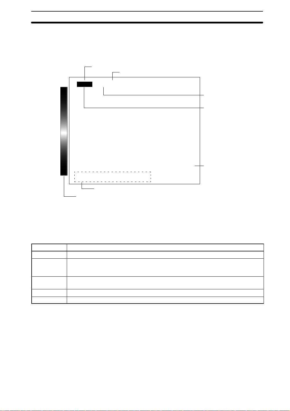
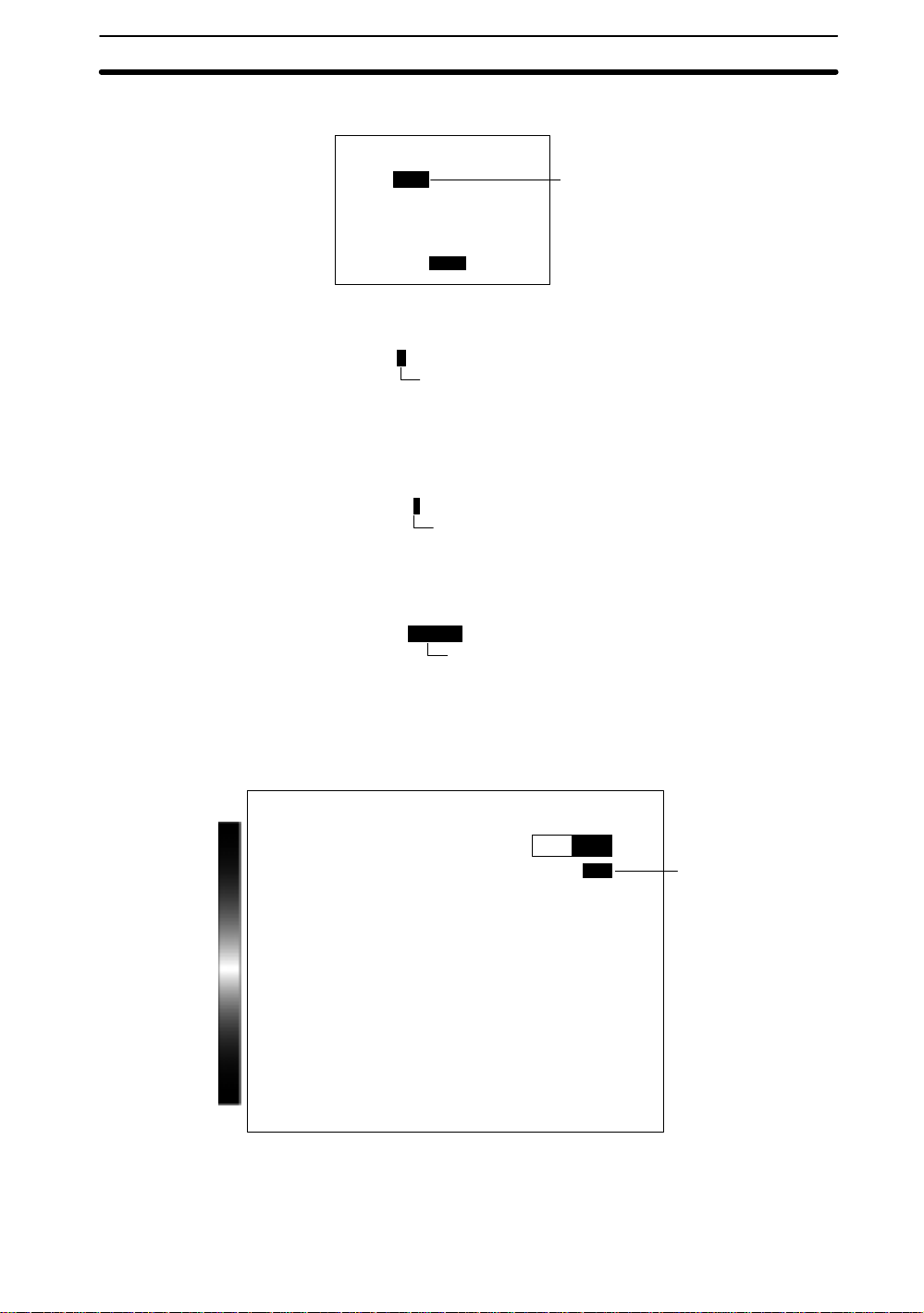
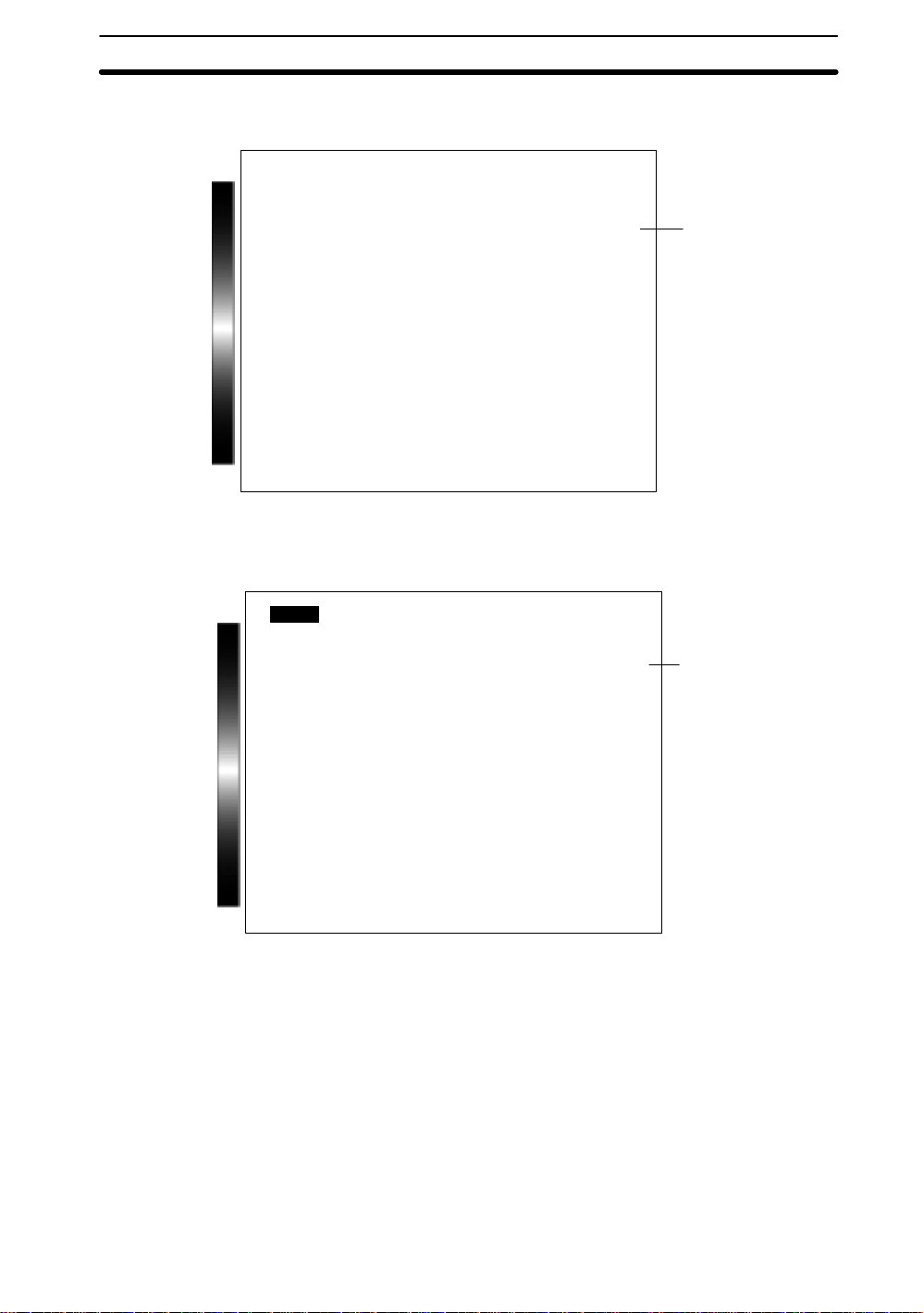
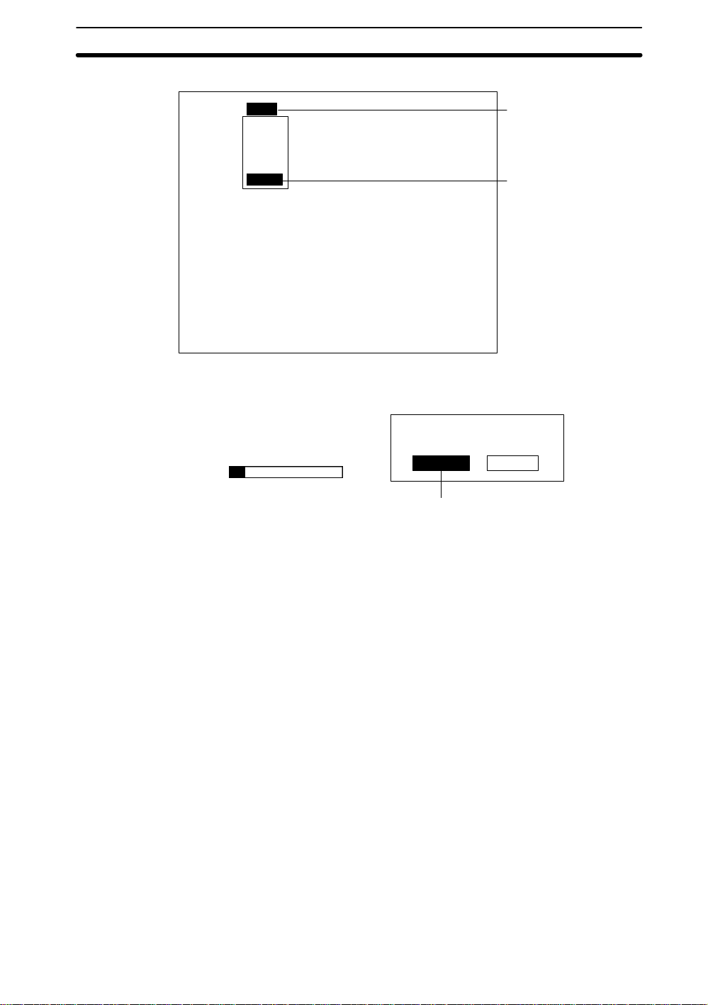
2-1-1 Screen Displays
— Filter/Pickup —
The F400 is operated by selecting functions from the screen. Highlighted text indicates the current cursor position. The screen is shown in the following diagram.
Scene number
B Mark
---- --ms
Color thr
Mode
Cursor
position
Displayed
image
Scene
Number
B Mark
Mode
Scn 0BMONB
Key operations
Color bar
The current scene number is displayed. There are 16 scenes that can be created to
change the measurement conditions easily .
Options will appear when an item with the B mark is selected.
The current operating mode is displayed. The modes are Set, Monitor, Run, System,
and Save. The operating modes are described in the following table.
Mode Meaning
SET Used to set measurement conditions.
MON (Monitor) Used to confirm whether or not the measurement is being performed correctly under the set
RUN Used to perform object measurements. Outputs measurement results to an external device
SYS (System) Used to make F400 system settings.
SAVE Saves settings to flash memory. Always save altered settings before exiting.
conditions and make adjustments if required. In this mode, measurement results are
displayed on the video monitor only and are not output to an external device.
via terminal blocks or RS-232C.
Cursor
The selected text is highlighted.
Position
Displayed
Image
Key
Operations
Color Bar
The type of image displayed on the video monitor is shown. Refer to
Changing Displayed Images
The keys that can be used and their corresponding functions are displayed at the bottom of the screen.
The F400 will be in Color Filter Mode if the color bar is displayed and in Color Pickup
Mode if the color bar is not displayed.
2-1-2 Input Devices
The menu operations are performed from either the Console or the RS-232C port.
8
Section 5-4-2
. →p. 103
— Filter/Pickup —
Page 17
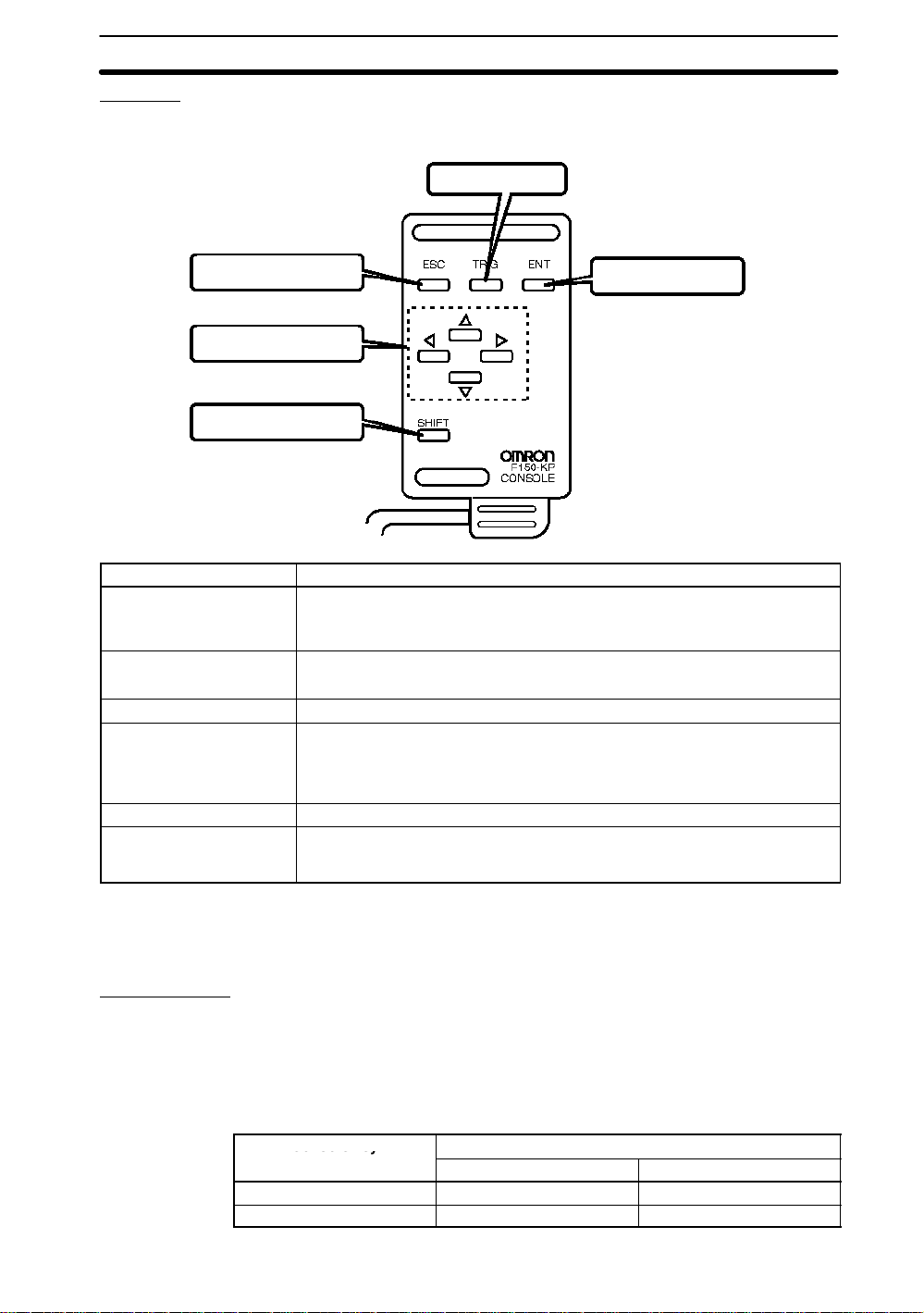
Console
Co so e ey
2-1SectionMenu Operations
The Console is used to perform menu operations. Be sure to familiarize yourself with
Console operations before actually using the menus.
TRIG (trigger) Key
ESC (escape) Key
Up, Down, Left, and
Right Cursor Keys
SHIFT Key
Key Function
ESC: Escape Key ESC Key functions differ depending on the screen currently displayed. Refer to
TRIG: Trigger Key Starts object measurement.
ENT: Enter Key Executes a function or sets a value.
Up and Down Keys Used to move the cursor up and down to select items.
Left and Right Keys Used to move the cursor left or right to select items.
SHIFT Key Must be pressed in combination with another key to have any effect. Specific
the explanations for individual screens. (See note.)
Interrupts processing and returns the user to the previous menu display.
Picks up a color when in Color Pickup Mode.
The Up Key will increase a value by 1 and the Down Key will decrease a value
by 1. Continue pressing the Up or Down Key to quickly increase or decrease a
value.
functions are assigned to SHIFT +
Refer to the explanations for individual screens.
another key
ENT (enter) Key
for specific screens. (See note.)
RS-232C Port
Note Possible to change assigned key functions or to assign new functions such as chang-
ing scenes or displays. Changed key allocations are effective only in the Monitor or
Run mode. Refer to
Section 5-5 Key Allocation
. →p. 106
There are keyboard key combinations for input via RS-232C that correspond to the
Console keys when in Run Mode. Refer to
Section 6-2-3 Input Command List
→p. 122
The keyboard key combinations are shown in the following table. The key codes
shown on the right in the following table can be input from an external device to perform the same functions as the Console keys shown on the left.
Console key
Key Code
ESC CTRL + [ ($1B)
TRIG CTRL + A ($01)
RS-232C input
.
9
Page 18
Console key RS-232C inputConsole key
ENT CTRL + M ($0D)
Up Key CTRL + E ($05)
Down Key CTRL + X ($18)
Left Key CTRL + S ($13)
Right Key CTRL + D ($04)
SHIFT + ESC TAB, CTRL + I ($09)
SHIFT + TRIG CTRL + T ($14)
SHIFT + ENT CTRL + R ($12)
SHIFT + Up Key CTRL + W ($17)
SHIFT + Down Key CTRL +Z ($1A)
Note 1. Commands cannot be input during menu operation.
2. Input CTRL + Q to re-input commands to change from the menu operation to
command input.
2-1SectionMenu Operations
CodeKey
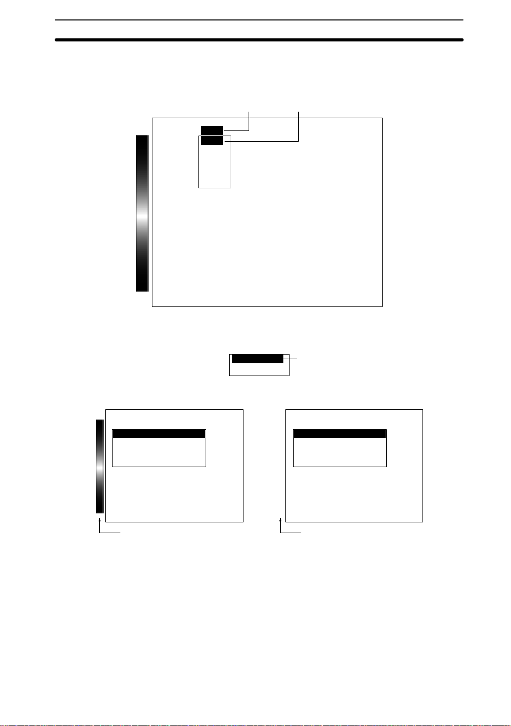
2-1-3 Menu Tree
F400 menus are hierarchical. The cursor is moved to the required functions to set
measurement conditions. Use the following procedure to move around the menu
tree.
Menu Tree:
1. Move the cursor to the desired function using the Up, Down, Left, and Right
Cursor Keys.
2. Press the ENT Key. In this example, the cursor will move to the Adjust menu.
Repeat this step to move to lower levels.
3. Press the ESC Key. The display will move to the previous menu level (i.e., the
screen shown in step (1)).
→p. 5
Adjust
Position compensation
Measurement region
Expression
Adjust
Position compensation
Measurement region
Expression
Adjust
Region
— Filter/Pickup —
1
2
2-1-4 Inputting Values
This section explains how to input numeric values when setting measurement conditions. There are two input methods.
Specifying the Input Digit
Specifying the input digit is used mainly for setting judgements and system conditions.
10
— Filter/Pickup —
Page 19
2-1SectionMenu Operations
1. Move the cursor to the item for which a value is to be changed and press the ENT
Key. The cursor size will change to a cursor the size of a single digit.
Correlation : 79 [80:100]
Position X : 180.000
[ 0.000 : 511.000]
Position Y : 30.000
[ 0.000 : 483.000]
Speed : 2B
End
2. Using the Left and Right Keys, move the cursor to the digit to be changed.
Position X: 180.000
[00000.000: 511.000]
1
2
3. Use the Up and Down Keys to change the value.
The Up Key will increase the value by 1 and the Down Key will decrease the
value by 1.
Position X: 180.000
[00100.000: 511.000]
3
4. Press the ENT Key when all digits have been changed as desired. The value will
be set.
Position X: 180.000
[190.000: 511.000]
4
Increasing and Decreasing Values
Values are increased or decreased mainly when setting binary levels and background suppression levels.
1. Move the cursor to the item for which the value is to be changed.
Binary level
↑↓:Move ←→:Change
2. Using the Left and Right Keys, change the numeric value. The Right Key will
increase the value by 1 and the Left Key will decrease the value by 1. The SHIFT
+ Right Key will increase the value by 10. The SHIFT + Left Key will decrease the
value by 10.
Upper[255]
Lower[128]
Reverse
Auto
OK
1
11
Page 20
2-1SectionMenu Operations
3. Use the Up and Down Keys to move to the next item. The numeric value will be
set.
Upper[200]
Lower[128]
3
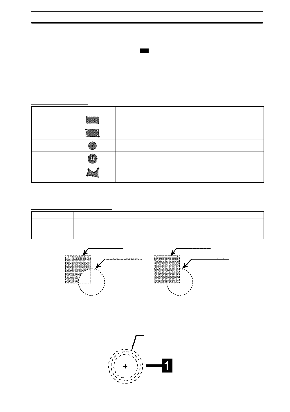
2-1-5 Drawing Measurement Regions
— Filter/Pickup —
This section explains drawing methods for model and measurement regions.
Use the Up, Down, Left, or Right Keys to move from one drawing point to another.
Press the Shift Key together with any one of these keys to move at a faster rate.
Types of Drawings
Type Drawing method
Box Set two diagonally opposing corners.
Ellipse Set two diagonally opposing corners of a rectangle enclosing the
Circle Set the center and radius.
Circumference Set the center and radius. and then the line width.
Polygon Specify up to 10 neighboring vertices. After specifying the last point,
ellipse.
press the ENT Key twice and it will be joined to the first point and the
region will be drawn.
Note The type and number of drawings that can be created depends on the function in
which the drawings are being used.
Drawing Method (OR/NOT)
Drawing mode Meaning
OR Registers drawings as models or regions. If multiple drawings are made, all drawings will
NOT Used to delete part of a region.
be registered as one region.
1st figure (OR) 2nd figure (OR)
2nd figure (NOT)
Example 1: Drawing a Circumference
1. Using the Cursor Keys, set the center of the circle and press the ENT Key. The
center of the circle will be set. Use the SHIFT + Cursor Keys to move the cursor
quickly.
12
1st figure (NOT)
The middle line is
the base of the
circumferences.
Page 21
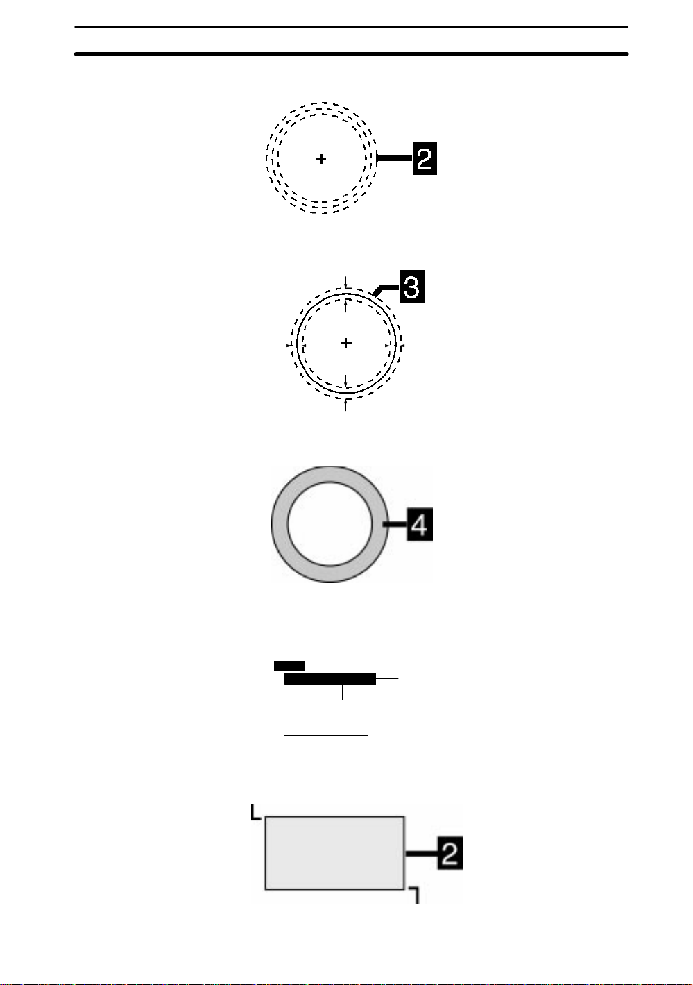
2-1SectionMenu Operations
2. Use the Up and Down Keys to specify the radius and press the ENT Key. The
arrows for specifying the line width for the circumference will be displayed.
3. Use the Up and Down Keys to set the line width. The arrows for specifying the
line width will be displayed.
4. Press the ENT Key. The drawing will be set and the drawn region will be displayed in white.
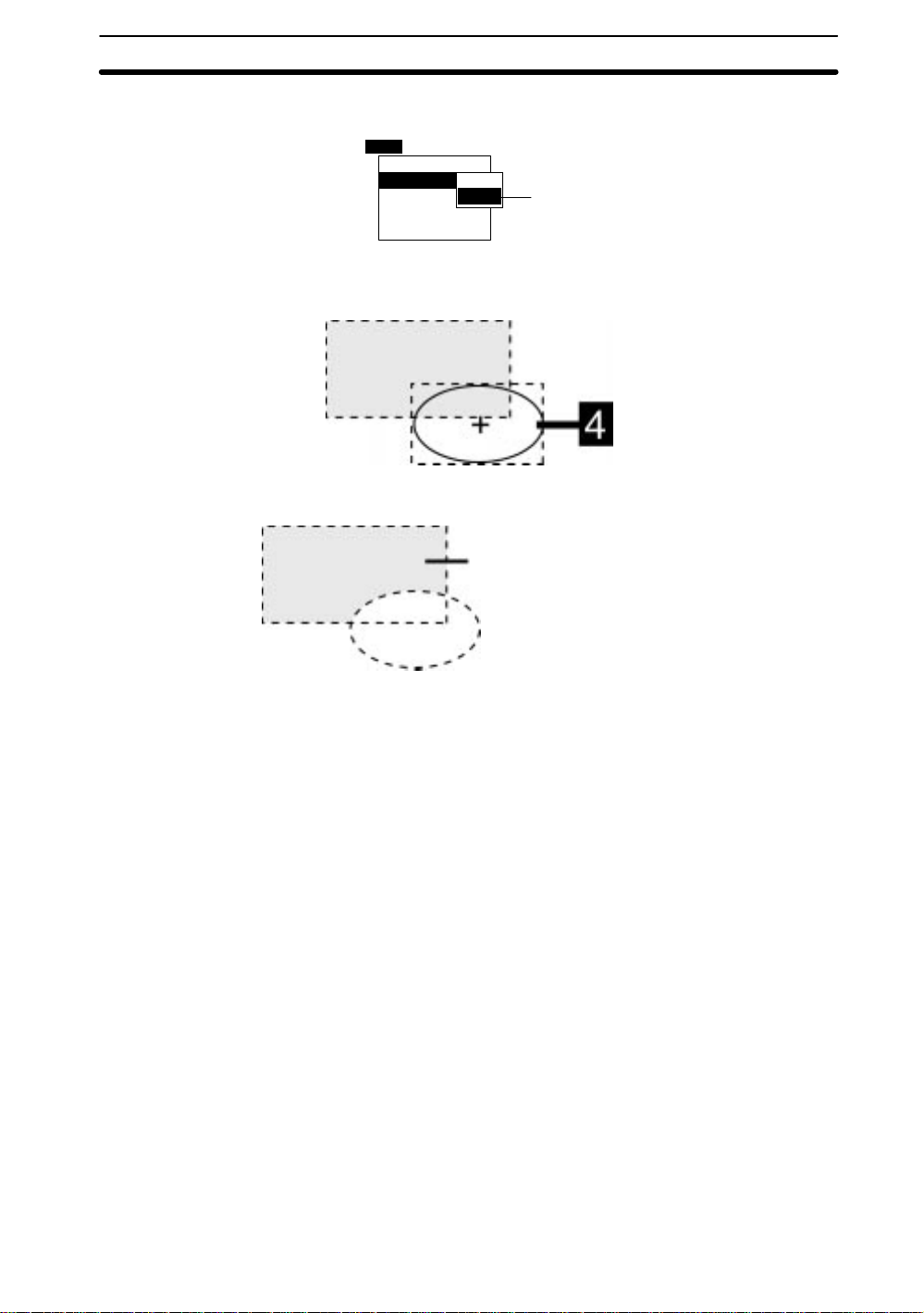
Example 2: Deleting Part of a Drawing
1. Select OR mode in the first drawing (a box for this example) and press the ENT
Key. The arrow for drawing a box will be displayed.
New
2. Set two diagonally opposing corner points to draw the box. Use the SHIFT + Cur-
sor Keys to move the cursor quickly.
1st point
Box
Ellipse
Circle
Circumference
Polygon
OR
NOT
1
2nd point
13
Page 22
2-2SectionStarting and Quitting
3. Select NOT mode in the second drawing (an ellipse in this example) and press
the ENT Key. The arrow for drawing an ellipse will be displayed.
Add
Box
Ellipse
Circle
Circumference
Polygon
4. Set two diagonally opposing corner points of a rectangle enclosing the ellipse to
draw the ellipse.
The overlapping section of the box and ellipse will be deleted.
OR
NOT
This section will be the region.
3
2-2 Starting and Quitting
2-2-1 Starting
Use the following procedure to start and quit operation.
Note Be sure to refer to the
the power supply or grounding the unit.
Setup Manual→2-2 Connections
1. Be sure that the basic F400 components have been connected correctly.
→
Setup Manual
2. Turn ON the power supply to the monitor.
Setup Manual (Z130)
— Filter/Pickup —
when connecting components or wiring
and
2-3 Power Supply and Ground
14
Page 23
3. Turn ON the power supply to the F400.
The title page will be displayed.
2-2SectionStarting and Quitting
Vision Inspection System
F400-C10 Series
Color-Gray Menu Software
(C)Copyright OMRON Corporation
4. After a short pause, the main F400 screen will be displayed.
The following screen will appear the first time power is turned ON.
Scn 0BMONB
Ver.2.00
1998-1999
All Rights Reserved
---- --ms
2
3
Note The startup scene and startup mode that appear when power is turned ON can be set.
Use these settings to make daily operation more efficient once the F400 is ready for
actual operation.
→
Startup Mode
2-2-2 Selecting Scene Modes
The F400 has two scene modes: Color Filter and Color PickUp. Select the appropriate measurement mode for the application.
Refer to
Select the scene mode when setting conditions for a scene for the first time.
Features
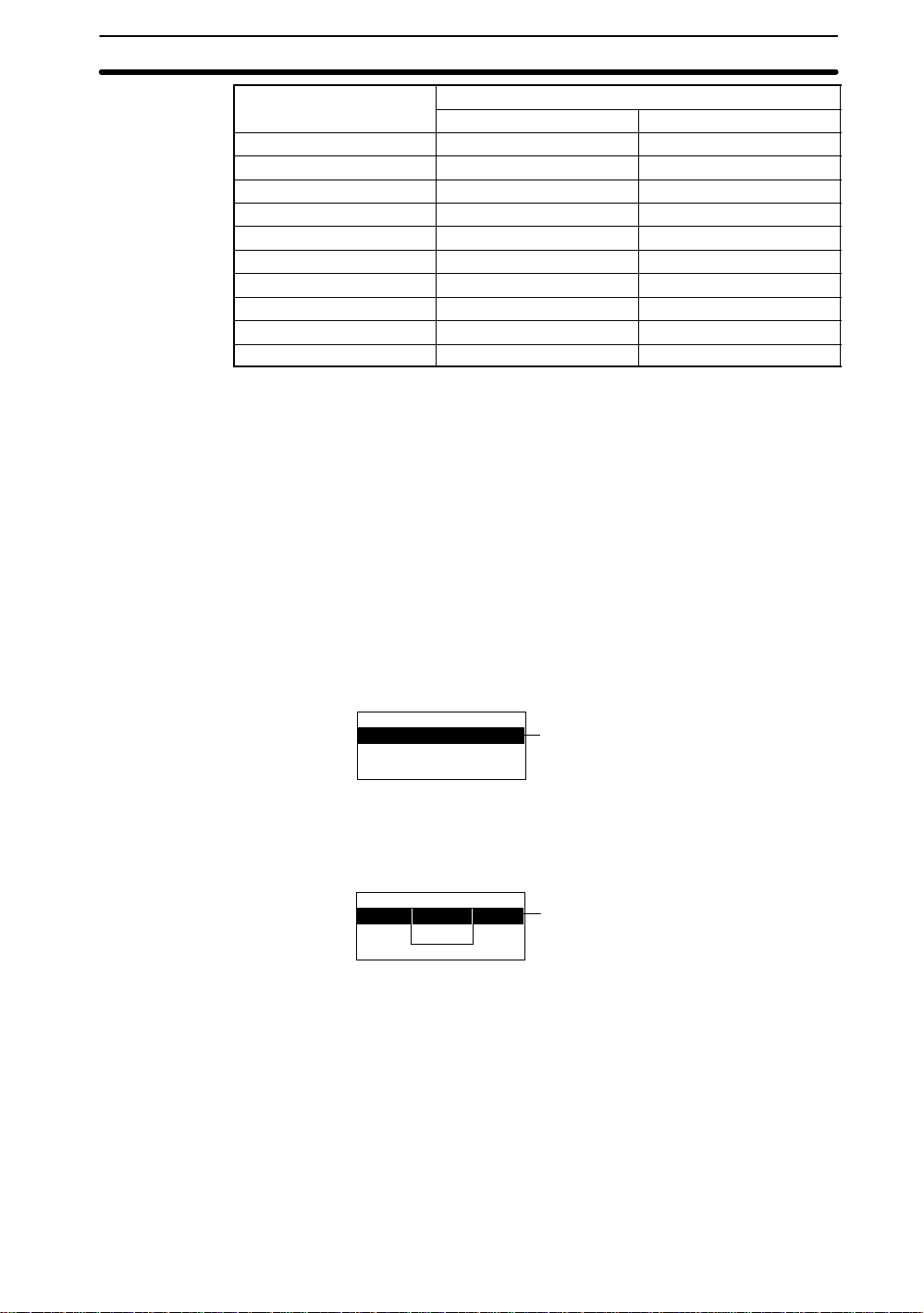
1. Select MON (Monitor) and press the ENT Key
in the
Introduction Manual (Z131)
Color thr
on p. 107
— Filter/Pickup —
→p. 5
15
Page 24
2-2SectionStarting and Quitting
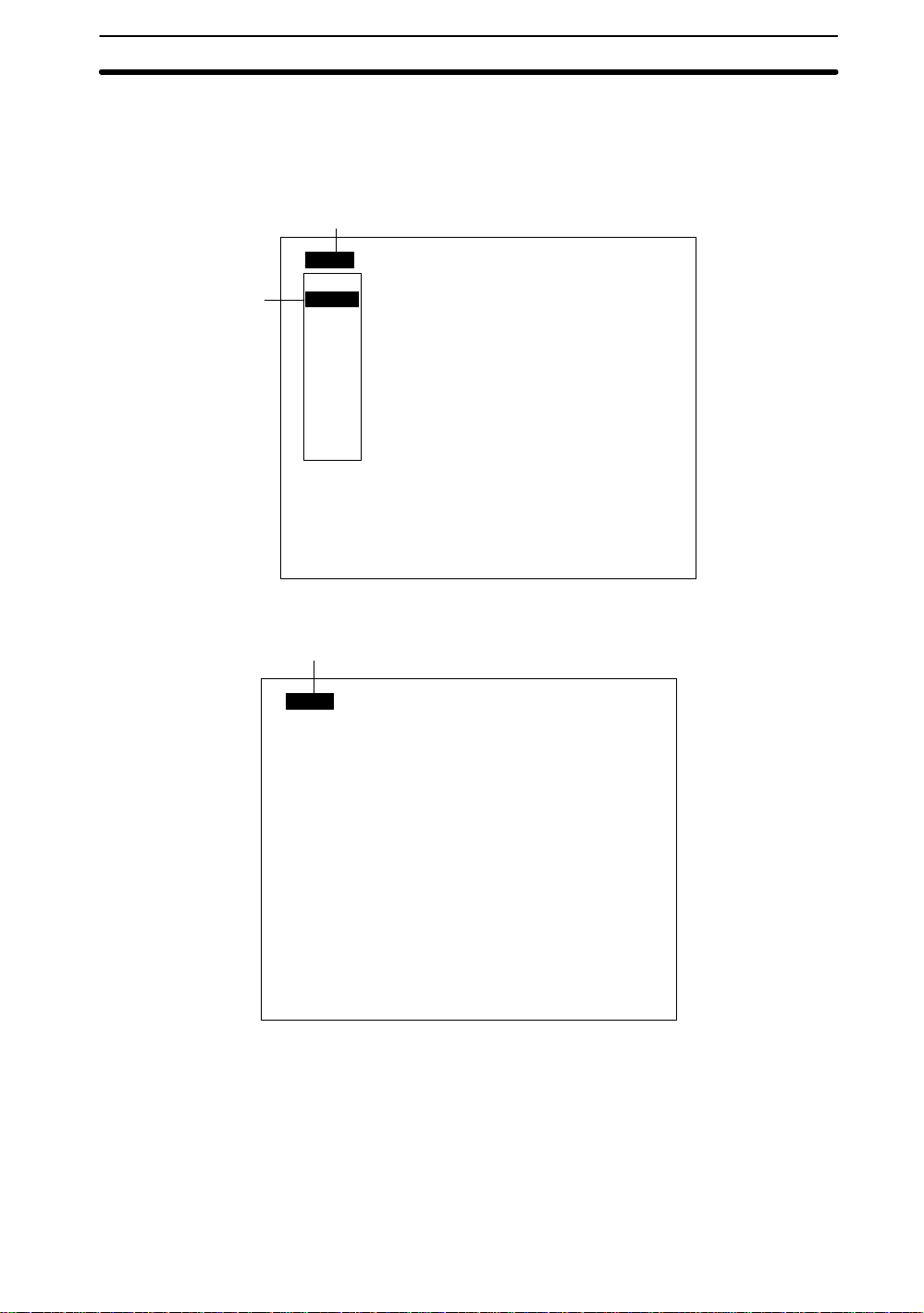
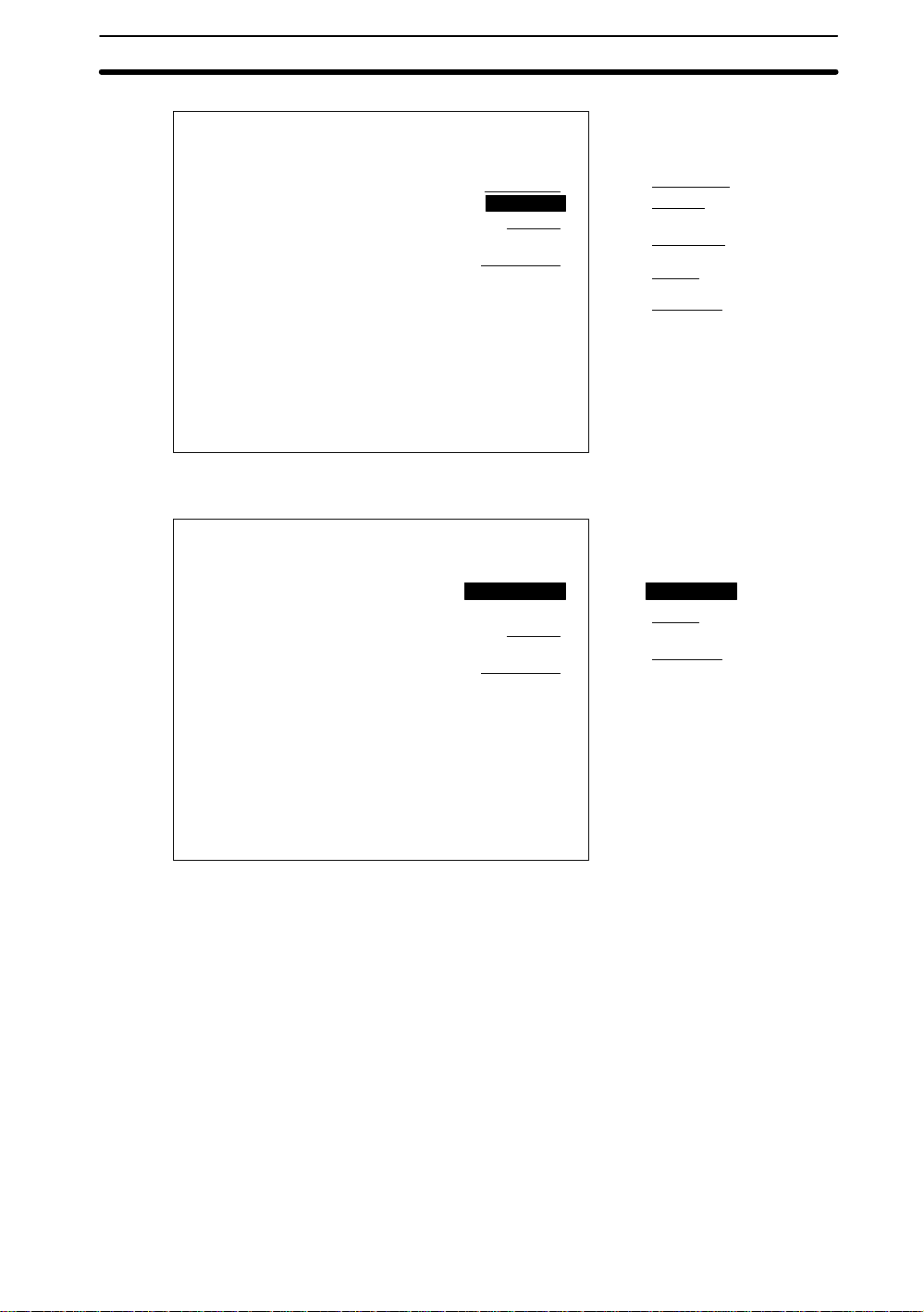
2. Select SET to display a list of scene processing options. The options will not be
displayed if measurement conditions are already set for the selected scene number. The scene number must be changed or the settings cleared before the
options can be changed.
12
Scn 0BMONB
SET
MON
RUN
SYS
SAVE
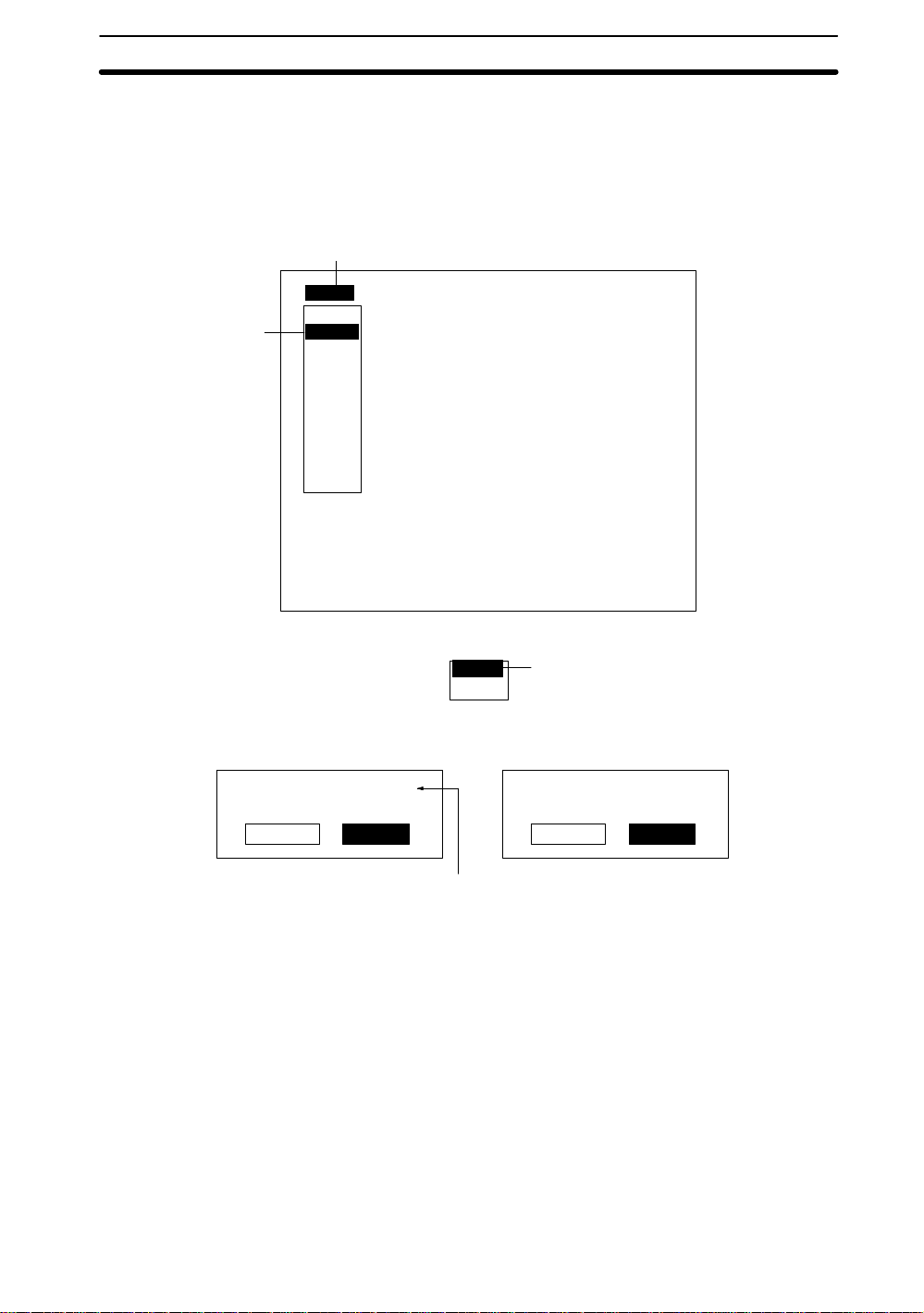
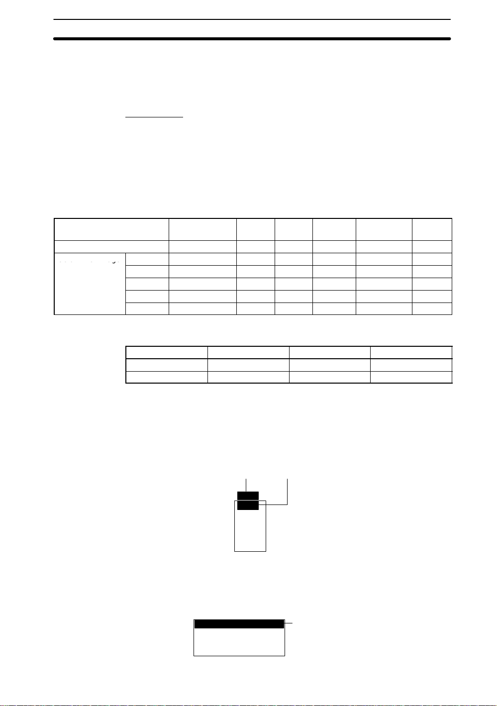
3. Select either
Color filter
screen for the selected scene mode will be displayed.
Settings screen for Color Filter Mode
Settings
Adjust
Position compensation
Measurement region
Expression
or
Color pickup
Color filter
Color pickup
---- --ms
Color thr
and press the ENT Key. The settings
3
Settings screen for Color Pickup
Mode
Settings
Adjust
Position compensation
Measurement region
Expression
Color bar displayed. No color bar displayed.
Note Changing between Color Filter and Color Pickup Modes
To change the scene mode for selected scenes, clear the scene and then change the
scene mode.
→
2-2-3 Changing Scenes
All the settings for measurement conditions are input for a specific scene. Up to 16
scenes can be set, numbered from 0 to 15. Scenes can be changed to switch between
different measurement conditions for different measurement setups or measurement
objects. Scene 0 will be displayed by default when the power is turned ON. Setup can
be changed by simply changing scenes. Refer to
16
Color thr
Copying and Clearing Scenes
Scene
on p. 17
in the
Color thr
— Filter/Pickup —
Glossary
on page 145.
Page 25
2-2SectionStarting and Quitting
1. Place the cursor on the scene number displayed on the screen (Scn 0 in this
example) and press the ENT Key. A list of scene numbers will be displayed.
Move the cursor using the Down Key to display the next group of scene numbers
from 9 to 15.
2. Select a new scene number.
1
Scn 0BMONB
Scn 0
2
3. Press the ENT Key to display the selected scene.
Scn 1
Scn 2
Scn 3
Scn 4
Scn 5
Scn 6
Scn 7
Scn 8
↑ ↓
---- --ms
Color thr
3
Scn 2BMONB
---- --ms
Note Commands to switch scenes can be input from external devices when in Monitor or
Run Mode.
Refer to
RS-232C
I/O Format
. →p. 112, 122
in
6-1 Terminal Blocks
2-2-4 Copying and Clearing Scenes
This section explains how to copy and clear scene data. Clear scene data before
changing the scene mode to either Color Filter or Color Pickup Mode.
Color thr
and
List of Input Commands
— Filter/Pickup —
in
17
Page 26
2-2SectionStarting and Quitting
1. Place the cursor on the scene number displayed on the main screen (Scn 0 in this
example) and press the ENT Key. A list of scene numbers will be displayed.
Move the cursor using the Down Key to display the next group of scene numbers
from 9 to 15.
2. Press SHIFT + ESC Keys on the scene number to be copied or cleared. The two
processing options will be displayed.
1
Scn 0BMONB
Scn 0
2
3. Select
When
Original scene : Scn 0B
Execute Cancel
Scn 1
Scn 2
Scn 3
Scn 4
Scn 5
Scn 6
Scn 7
Scn 8
↑ ↓
Copy
Copy
or
is selected
Clear
---- --ms
Color thr
. A confirmation message will be displayed.
Copy
Clear
3
When
Clear
is selected
This scene data
will be cleared.
Execute Cancel
Place the cursor on Scn 0 and press
the ENT Key to display a list of scene
numbers.
4. Move the cursor to Execute and press the ENT Key. The data for the selected
2-2-5 Quitting
The user can quit the F400 and turn OFF the power at any time except while saving or
loading data. Save all measurement settings to flash memory before quitting. The
data in flash memory is loaded each time the F400 is started. Any changes made will
be lost unless they are saved to the flash memory.
Note The measurement images and sample images in memory are also cleared when the
power is turned OFF. These images cannot be saved to flash memory , but they can be
backed up on a computer if required. Refer to
1. Move the cursor to
18
scene will be copied or cleared and the display will return to the main screen.
— Filter/Pickup —
displayed.
5-3 Backup
MON
and press the ENT Key . A list of operation modes will be
. →p. 97
Page 27
2-2SectionStarting and Quitting
2. Select
3. Move the cursor to Execute and press the ENT Key. The save will be executed
Saving data
SAVE
. A confirmation message will be displayed.
Scn 0BMONB
SET
MON
RUN
SYS
SAVE
and a progress box will be displayed.
---- --ms
1
2
Color thr
Setting data will be saved.
Execute Cancel
3
Note Do not input the RESET command or turn OFF the power while saving data. The data
may be lost, and the F400 may not operate properly the next time it is started.
When the data has been saved, the display will return to the main screen.
4. Turn OFF the power to the F400.
19
Page 28

SECTION 3
Settings
This section describes how to set measurement conditions for F400 visual inspections.
The following headings are used in this section to indicate the measurement modes to which an operation is appli-
cable.
3-1 Adjusting Images 22. . . . . . . . . . . . . . . . . . . . . . . . . . . . .
3-1-1 Shutter Speed 24. . . . . . . . . . . . . . . . . . . . . . . . . . . . . . .
3-1-2 Applying Color Filters 24. . . . . . . . . . . . . . . . . . . . . . . .
3-1-3 Creating a Color Filter 26. . . . . . . . . . . . . . . . . . . . . . . .
3-1-4 Picking Up Measurement Colors 28. . . . . . . . . . . . . . . .
3-1-5 Filtering 33. . . . . . . . . . . . . . . . . . . . . . . . . . . . . . . . . . .
3-1-6 Background Suppression 34. . . . . . . . . . . . . . . . . . . . . .
3-1-7 Output Calibration 36. . . . . . . . . . . . . . . . . . . . . . . . . . .
3-2 Position Compensation 37. . . . . . . . . . . . . . . . . . . . . . . . .
3-2-1 Adjusting Images for Easier Position Compensation 38.
3-2-2 Setting Position Compensation Regions 38. . . . . . . . . . .
3-2-3 Searches 40. . . . . . . . . . . . . . . . . . . . . . . . . . . . . . . . . . .
3-2-4 Position Compensation using Edges 43. . . . . . . . . . . . .
3-2-5 Area and Center of Gravity, and Center of
Gravity and Axis Angle 46. . . . . . . . . . . . . . . . . . . . . . .
3-3 Measurement Methods 50. . . . . . . . . . . . . . . . . . . . . . . . .
3-3-1 Measurement Regions 50. . . . . . . . . . . . . . . . . . . . . . . .
3-3-2 Surface Defects 52. . . . . . . . . . . . . . . . . . . . . . . . . . . . . .
3-3-3 Searches 55. . . . . . . . . . . . . . . . . . . . . . . . . . . . . . . . . . .
3-3-4 Edge Processing 63. . . . . . . . . . . . . . . . . . . . . . . . . . . . .
3-3-5 Area and Center of Gravity, and Center of
Gravity and Axis Angle 67. . . . . . . . . . . . . . . . . . . . . . .
3-4 Expressions 75. . . . . . . . . . . . . . . . . . . . . . . . . . . . . . . . . .
— Color Filter —
— Color Pickup —
— Filter/Pickup —
21
Page 29
3-1 Adjusting Images
Co o e age
Images displayed on the video monitor can be adjusted for easier measurement.
Before adjusting the image on the monitor, however, adjust lighting and camera focus
to clearly display the measurement object in the center of the screen.
Note White Balance
Depending on the inspection environment and type of lighting, even white images
read by the camera may appear somewhat colored. Refer to the
Setup Manual (Z130)
before setting the light and adjusting the image.
for information on lighting methods. Adjust the white balance
White Balance
Different adjustments are possible depending on the scene mode and type of image.
Refer to the following table for items that can be adjusted.
Color Filter Mode
Image Color filter Shutter
Color Yes Yes Yes No No No
Color Filter Image
Colorgray No Yes Yes Yes Yes Yes
Red No Yes Yes No Yes Yes
Green No Yes Yes No Yes Yes
Blue No Yes Yes No Yes Yes
Gray No Yes Yes No Yes Yes
speed
Calibra-
tion
Color
selection
2-6 Lighting
→ p. 96
Background
suppression
3-1SectionAdjusting Images
in the
Filtering
Color Pickup Mode
Image Shutter speed Color pickup Calibration
Color Yes Yes Yes
Pickup color Yes Yes Yes
1. Move the cursor to the operation mode in the main screen (Monitor in this example) and press the ENT Key. A list of modes will be displayed.
2. Move the cursor to
SET
and press the ENT Key. A list of setting modes will be
displayed.
12
Scn 0BMONB
3. Move the cursor to
ment) Window will be displayed.
Settings
Adjust
Position compensation
Measurement region
Expression
SET
MON
RUN
SYS
SAVE
Adjust
and press the ENT Key. The Adjust (image adjust-
3
22
Page 30
Color Filter Mode
Adjust
3-1SectionAdjusting Images
←→:Switch
Color Pickup Mode
Adjust
Color filter
Colorgray
Shutter
1/2000s
Calibration
512.000
Color thr
Pickup color
Shutter
1/2000s
Calibration
512.000
Color select
Filtering
OFF
BGS levels
←→
0:255
Shutter
1/2000s
Calibration
512.000
Colorgray thr
Pickup color
p
←→
Shutter
1/2000s
Calibration
512.000
Color thr
Pick up thr
←→:Switch
Adjustment items are underlined. Use Left or
Right Key to change the displayed item.
Note 1. If adjustment items are hard to read, use the SHIFT + ESC Keys to switch
between clear and filled backgrounds. Select the background that makes the
screen most legible. Refer to
5-4 Display Settings.
2. When temporarily switching between through or freeze images while performing
image adjustment, use the SHIFT + Up Key or SHIFT + Down Key to select the
appropriate type of display for the image.
23
Page 31

3-1SectionAdjusting Images
3-1-1 Shutter Speed
Change the shutter speed when the object is moving quickly, causing the image to be
blurred. The shutter speed can be changed for any displayed image.
1. Move the cursor to
the ENT Key. The Shutter Speed Window will be displayed. Use the Left and
Right Keys to change the list of options if
Adjust
Movement speed Shutter speed
Slow
Fast
Shutter
1/100 s
1/500 s
1/2000 s*
1/10000 s
*Default value
on the screen for the image to be adjusted and press
Color filter
Colorgray
1/2000s
Calibration
512.000
Shutter
Shutter
— Filter/Pickup —
does not appear on the list.
1
←→:Switch
2. Use the Left and Right Keys to change the shutter speed. Check the image
while changing the shutter speed.
Shutter
1/2000s
1/100 s 1/500 s 1/2000 s 1/10000 s
3. Press the ENT Key. The shutter speed setting will be saved and the display will
return to the Adjust (image adjustment) Window.
3-1-2 Applying Color Filters
A color filter can be applied to the image read by the camera to emphasize particular
colors and make a grayscale image for easier measurement. The F400 has five color
filters. Select a filter color that will make the color to be detected lighter (e.g., surface
defects or marks). This section explains how to select color filters.
Refer to the
Introduction Manual (Z131)
Color thr
2
— Color Filter —
for information on colors. → p. 39
24
Page 32

3-1SectionAdjusting Images
Color Function
Red Emphasizes (lightens) red.
Green Emphasizes (lightens) green
Blue Emphasizes (lightens) blue.
Gray Changes to a grayscale image (standard black and white image).
Colorgray Creates a filter to suit the color to be detected.
1. Move the cursor to the color filter (Colorgray in this example) and press the ENT
Key. The Color Filter Window will be displayed. Use the Left and Right Keys to
change the list of options if
Adjust
Color Filter
does not appear on the list.
Color filter
Colorgray
1
Shutter
1/2000s
Calibration
512.000
Color thr
←→:Switch
2. Use the Left and Right Keys to change the color filter. Check image while changing the color filter.
Color filter
Colorgray
Colorgray Red Green Blue Grey
2
3. Press the ENT Key. The color filter setting will be saved and the display will return
to the Adjust (image adjustment) Window.
Note The selected color filter will be used for measurement. A different color filter can be
set for position displacement compensation.
Refer to
3-2-1 Adjusting Images for Easier Position Compensation
→ p. 38
25
Page 33

3-1SectionAdjusting Images
3-1-3 Creating a Color Filter
When the F400 color filters cannot emphasize a particular color in an image, a new
filter is created to suit the detection color . The color image is converted to a grayscale
image based on the hue and saturation settings. Adjust the hue and saturation settings while referring to the displayed image and create a filter that best emphasizes
the detection color. This section explains the procedure for creating color filters.
Refer to the
Hue The colors red, yellow, green, blue, and purple. Select the color that
Color band The range of colors to be measured based on the set color.
Saturation The vividness of the color. Areas outside the saturation range are
Color filters are created by selecting the Colorgray filter function. Set a colorgray filter
in advance using the Color Filter settings.
Refer to
1. Move the cursor to
Window will be displayed. The image will be converted to a color grayscale
image and a A mark will appear on the color bar. Use the Left and Right Keys to
change the list of options if
Introduction Manual (Z131)
will highlight the section to be detected in the gray image.
changed to white or black and excluded from measurement. The
saturation range is set using upper and lower limits.
3-1-2 Applying Color Filters
Color select
Color select
— Color Filter —
for information on colors. → p. 39
→ p. 24
and press the ENT Key. The Color Selection
does not appear on the list.
26
Adjust
Color select
Filtering
OFF
BGS levels
0:255
Shutter
1/2000s
Calibration
512.000
Colorgray thr
←→:Switch
2. Use the Up and Down Keys to move the A mark and select the color. The image
displayed on the screen will change as the A mark scrolls through the colors.
Press SHIFT + Up and Down Keys to scroll through the colors quickly. Use the
Left and Right Keys to switch to a color image and check the color.
1
Page 34

3-1SectionAdjusting Images
3. Press the SHIFT + ENT Keys to select the color band. Pressing the SHIFT + ENT
Keys will alternately change between ±90_ and ±180_.
The number indicates the cursor position. Use this
number as reference for setting the filter color.
(For example: set to the same filter color for posi-
2
tion adjustment and measurement.
Adjust (Color select)
A
↑↓:Select SFT+ENT:Band
4. Press the ENT Key. The set color and color band settings will be saved. Perform
steps 5 to 9 to set the saturation range, otherwise go straight to step 10.
Note The selected color filter is used for measurement. A different color filter can be set for
position displacement compensation.
Refer to
Setting the Chroma Range
5. Press the SHIFT + ESC Keys. The Saturation Range Settings Window will be
displayed.
39
Color band
±90°
3
3-2-1Adjusting Images for Easier Position Compensation
→ p. 38
27
Page 35

3-1SectionAdjusting Images
6. User the Left and Right Keys to change the upper limit. The displayed image will
change as the setting is changed. Use the SHIFT + Left and Right Keys to
increase or decrease the value by 10.
Saturation Range Settings
Lower limit Upper limit
Color select (Saturation range)
6
Upper [80]
Lower [ 0]
OK
7
8
↑↓:Move ←→:Change
7. Repeat the same operation to change the lower limit.
OK
8. Move the cursor to
Selection Window.
9. Press the ENT Key again. The saturation range will be saved.
10. Press the ESC Key to close the Color Selection Window. The display will return
to the Adjust (image adjustment) Window.
and press the ENT Key. The display will return to the Color
3-1-4 Picking Up Measurement Colors
Simply click the desired color to extract and measure it. All other colors will be treated
as background. The extracted color is called the pickup color. Up to 8 pickup colors
can be registered. Display the Adjust (image adjustment) Window for Color Pickup
Mode before starting color pickup.
Refer to
Selecting a Color
First, select the color to be picked up in the color image. The F400 will extract the
selected color and will automatically switch to a pickup color image. All other areas of
the image will be changed to black in the display. Repeat the color selection process
until all the desired colors have been extracted.
Color image
Move the cursor to the color to
be selected.
Pickup color0 Pickup color0
TRIG:Pick up SFT+ESC:Option
2-2-2 Selecting Scene Modes.
Press TRIG Key.
— Color Pickup —
→ p. 15
Pickup color image
Only the selected color will be
displayed.
ESC:UNDO
TRIG:Pick up SFT+ESC:Option
28
Page 36

Changing Cursor Size
If the cursor size does not match the size of section to be extracted, press the SHIFT +
ENT Keys to change the cursor size. (Max. 64 x 64 pix.)
Changing Background Color of Pickup Color
If the image is hard to see because the pickup color is similar to the background color,
press the SHIFT + TRIG Keys to change the background color that is available in five
different gradations.
Display Image and Margin
Press the SHIFT + ESC Keys on the color pickup display to display a dialog. Using
this dialog, change the display image or set the color parameter range for extracting
colors considering noise.
Display image : ColorB
Margin : 3B
Display Image
Colors can be extracted though monitoring image colors while switching the display
image between color image and two types of pickup color images.
3-1SectionAdjusting Images
End
Margin
Color image Pickup image
The color image
is displayed.
Pickup color1
TRIG:Pick up SFT+ESC:Option
The pickup color
currently being
extracted will be
displayed.
Pickup color1
TRIG:Pick up SFT+ESC:Option
When the margin is positive (+): Color parameter range will be widened by the set
margin for color pickup.
When the margin is negative (–): Color parameter range will be narrowed by the set
margin for color pickup and the colors outside the range will be treated as noise.
Narrow
Margin
Wide
–3
–2
–1
+1
+2
+3
Pickup image for all pickup
colors
All of the registered pickup
colors will be displayed.
Pickup color1
Pickup color registered during the
zero extraction.
TRIG:Pick up SFT+ESC:Option
0
• If all the colors subject to measurement cannot be
picked up, set the margin to a positive value.
• If colors not subject to measurement are also picked
up with much noise, set the margin to a negative value.
29
Page 37

3-1SectionAdjusting Images
1. Move the cursor to
Pickup color
and press the ENT Key. The Pickup Color Num-
ber Selection Window will be displayed.
Adjust
Pickup color
1
Shutter
1/2000s
Calibration
512.000
Color thr
←→:Switch
2. Use the Left and Right Keys to select the pickup color number to be registered.
The image read by the camera will not be displayed if no pickup colors have been
registered for the selected number. The pickup image will be displayed for registered pickup color numbers.
Color pickup
Color 0
2
←→:Change
Use the Left and Right Keys to scroll through the pickup
color numbers 0 to 7 in order.
Pickup
color 0
Pickup
color 1
Pickup
color 7
3. Press the ENT Key. The Color Pickup Window will be displayed and the color
pickup cursor will appear.
4. Move the cursor to the section for which the color is to be extracted and press the
TRIG Key. Color pickup will be performed for the specified section of the image.
The image will then change to a pickup color image and the selected color will be
displayed.
If the picked up color is hard to see, press the SHIFT + TRIG Keys to select one of
30
Page 38

3-1SectionAdjusting Images
five background gradations. Select the background gradation that will show the
pickup color in greatest contrast.
To change the display image or pickup color margin, press the SHIFT + ESC
Keys.
Registered pickup color number
Pickup color0
TRIG:Pick up SFT+ESC:Option
Color pickup cursor
4
5. Move the cursor to the next section to be extracted and press the TRIG Key.
Repeat this procedure to pick up all the colors for measurement.
Press the ESC Key to cancel colors selected using the TRIG Key. The last pickup
color selection will be canceled.
Pickup color0
4
ESC:UNDO
TRIG:Pick up SFT+ESC:Option
6. Press the ENT Key when all the desired colors have been extracted. The pickup
colors will be registered and the display will return to the Pickup Color Number
Selection Window. Repeat steps 2 to 5 to register more pickup colors.
31
Page 39

Changing and Clearing Pickup Colors
1. Move the cursor to
ber Selection Window will be displayed.
Adjust
←→:Switch
2. Use the Left and Right Keys to display the pickup color number to be changed or
cleared and press the ENT Key. The processing options will be displayed.
Pickup color
3-1SectionAdjusting Images
and press the ENT Key. The Pickup Color Num-
Pickup color
Shutter
1/2000s
Calibration
512.000
Color thr
1
Pickup color
←→:Change
Color 0
2
32
Page 40

3-1SectionAdjusting Images
3. Select either
When
The color pickup cursor
is displayed.
Pickup color0
TRIG:Pick up SFT+ESC:Option
Next, perform the same steps as for
color pickup.
4. When Clear has been selected, move the cursor to
3-1-5 Filtering
The image read by the Camera can be manipulated to create an image that is easier
to measure, by using smoothing or edge enhancement.
Smoothing displays a smoothed image with reduced noise. Smoothing allows suppression of the effects of uneven lighting due to an uneven or damaged surface.
Edge enhancement displays an image with enhanced edges between bright and dark
regions to compensate for blurred images.
Filtering can be performed only on images to which a color filter has been applied.
Filtering method Function
OFF No filtering.
Smoothing Displays a smooth image with reduced noise. Select either weak or
Enhance edges Displays an image with enhanced edges between bright and dark
Extract edges Displays an image with the edges between the bright and dark
Correct
Correct
is selected When
or
Correct
Clear
Clear
and press the ENT Key.
3
Clear
A confirmation message is
displayed.
is selected
Color 0 will be cleared.
Execute Cancel
4
Execute
Key. The selected pickup color settings will be cleared and the display will return
to the Adjust (image adjustment) Window.
strong smoothing.
regions.
regions extracted.
and press the ENT
— Color Filter —
33
Page 41

3-1SectionAdjusting Images
1. Move the cursor to the
Filtering
method (OFF in this example) and press the
ENT Key. The Filtering Window will be displayed. Use the Left and Right Keys to
change the list of options if
Filtering
does not appear on the list.
Adjust
Filtering
OFF
1
BGS levels
0:255
Shutter
1/2000s
Calibration
512.000
Red thr
←→:Switch
2. Use the Left and Right Keys to select the filtering method. Check the image
while selecting the appropriate filtering method.
Filtering
OFF
Use the Left and Right Keys to switch between weak smoothing,
strong smoothing, edge enhancement, and edge extraction.
OFF
Weak
smoothing
2
Strong
smoothing
3. Press the ENT Key. The filtering settings will be saved and the display will return
to the Adjust (image adjustment) Window.
Note The selected filtering method is used for measurement. Different filtering can be set
for position displacement compensation.
Refer to
3-2-1 Adjusting Images for Easier Position Compensation
3-1-6 Background Suppression
Background suppression (BGS) changes image areas with densities below the lower
limit to 0, and image areas with densities above the upper limit to 255. Image areas
with densities between the lower and upper limits are graded from 0 to 255 so that
only images with densities between the lower and upper limits are measured.
Monitor the image and set the upper and lower limits of the density to eliminate the
background.
Enhance
edges
Extract
edges
→ p. 38
— Color Filter —
34
Page 42

Example
3-1SectionAdjusting Images
Lower limit: 150 Upper limit: 255
Measurement object Density
Background Background density (cut)
1. Move the cursor to
The BGS Levels Setting Window will be displayed. Use the Left and Right Keys
to change the list of options if
Adjust
BGS levels
Image areas with densities of 149 or lower
will not be measured and the density will
be changed to 0.
Only image areas with densities between
150 and 255 will be measured. The whole
image is graded from 0 to 255.
(0:255 in this example) and press the ENT Key.
BGS levels
does not appear on the list.
Filtering
OFF
BGS levels
0:255
Shutter
1/2000s
Calibration
512.000
1
Red thr
←→:Switch
2. Use the Left and Right Keys to alter the upper limit. The displayed image will
change when the numeric values are changed. Use the SHIFT + Left and Right
Keys to increase or decrease the numeric value by 10.
3. Change the lower limit the same way.
BGS Level Setting
Lower limit Upper limit
2
Upper[200]
Lower[100]
OK
3
4
4. Move the cursor to OK and press the ENT Key.
Note The selected BGS level is used for measurement. Different BGS levels can be set for
position displacement compensation.
Refer to
3-2-1 Adjusting Images for Easier Position Compensation
→ p. 38
35
Page 43

3-1SectionAdjusting Images
3-1-7 Output Calibration
Calibration can be set to output the measurement results in physical units, such as
mm.
Set the relationship between the physical coordinates and the camera coordinates to
convert the measurement results from pixels to physical units, such as µm, mm, or
cm.
If calibration data is not set, the default settings will remain, and measurements using
the camera coordinates will be output.
For details, refer to
Default Settings
Coordinate system: Left-handed
Origin: Upper left corner of screen
Magnification: 1.000
Units: mm/pix
Setting
Origin Upper left*
Options Meaning
Lower left
Center
— Filter/Pickup —
Glossary
Select the position of the origin (0,0) of the coordinate system on the
screen.
. → p. 142
Origin
484 mm
(= 484 pixels)
512 mm (= 512 pixels)
Center
Upper left
Coordinate
system
Right-handed
Left-handed*
Magnification 0.001 to 9.999
(1.000*)
Units
µm/pix,
mm/pix*, or
cm/pix
Note The default settings are indicated by an asterisk (*).
Lower left
Select the coordinate system. The positive direction for angles will
depend on the coordinate system.
Upper
-left
origin
Left-handed System
Forward
direction
Lowerleft origin
Forward
direction
Center
origin
Forward
direction
Right-handed System
Upper
-left
origin
Forward
direction
Lowerleft origin
Forward
direction
Center
origin
Forward
direction
Set the actual measurement to which 1 pixel will correspond.
For example, an actual length of 10 mm could correspond to 100
pixels on the screen.
10 (mm)/100 (pix) = 0.1 (mm/pix). The magnification, therefore, would
be 0.1.
Set the units for conversion.
36
Page 44

3-2SectionPosition Compensation
1. Move the cursor to
Window will be displayed. Use the Left and Right Keys to change the list of
options if
Adjust
←→:Switch
2. Move the cursor to the item to be changed and press the ENT Key . Options are
available for items indicated by a Bmark. The magnification is changed by
changing the numeric value.
Calibration
Calibration
does not appear on the list.
and press the ENT Key . The Calibration Setting
Filtering
1/2000s
Calibration
512.000
Red thr
Red
Shutter
1
3. Press the ENT Key. The settings will be saved.
Origin : Upper leftB
Coordinate : LefthandB
Magnification: [1.000]
Unit : mm/pixB
End
5
4. Repeat steps 2 and 3 to change other settings.
5. When all settings have been made, move the cursor to
Key. The calibration settings will be saved and the display will return to the Adjust
(image adjustment) Window.
3-2 Position Compensation
Use position displacement compensation when the position and orientation of the
measurement objects are not consistent. The position of the measurement object is
compared to a reference position, the amount of displacement is calculated, and the
image is scrolled by that amount before a measurement is performed.
2, 3
End
and press the ENT
37
Page 45

Flow of Operation
3-2SectionPosition Compensation
Adjust the image for easier position compensation.
Set the measurement region for
position compensation.
Select the position compensation
method.
Set the position compensation
conditions.
1. Adjusting Images for Easier Position Compensation → p. 38
2. Setting Position Compensation Regions
3. Searches
4. Position Compensation using Edges
5. Area and Center of Gravity, and Center of Gravity and
Axis Angle
→ p. 40
→ p. 46
→ p. 38
→ p. 43
3-2-1 Adjusting Images for Easier Position Compensation
— Color Filter —
Different image conditions can be set for measurement and position compensation.
Refer to the procedures for setting measurement image conditions; the setting methods are the same.
Applying Color Filters to Images
Different color filters can be applied for measurement and for position compensation.
Refer to
3-1-2 Applying Color Filters
→ p. 24
Creating a Color Filter
Different color filters can be created for measurement and for position compensation.
Refer to
Filtering
Different filtering can be performed for measurement and for position compensation.
For example, smoothing may be selected to reduce noise for measurement and edge
enhancement may be selected for position compensation to highlight the edges of the
measurement object.
Refer to
Background Suppression
Different background suppression can be performed for measurement and for position compensation.
Refer to
3-1-3 Creating a Color Filter
3-1-5 Filtering
→ p. 33
→ p. 26
3-1-6 Background Suppression
→ p. 34
3-2-2 Setting Position Compensation Regions
The F400 has four methods of position compensation: Search, edge enhancement
and extraction (edge), area and center of gravity, and center of gravity and axis angle.
A measurement region must be set before position compensation can be performed.
Up to two regions can be set for each scene.
— Filter/Pickup —
38
Page 46

3-2SectionPosition Compensation
1. Move the cursor to
SET/Position compensation/Region
and press the ENT
Key. The Position Compensation Selection Window will be displayed. The window shown in step 2 will be displayed if
Position compensation
Color Pickup Mode.
Color Filter Mode Color Pickup Mode
Settings
Adjust
Position compensation
Measurement region
Expression
Adjust
Region
Color frz
Settings
Adjust
Position compensation
Measurement region
1
Expression
Color frz
2. Select the position compensation method and press the ENT Key. The setting
options for the selected method of position compensation will be displayed. The
method selected here will be registered for region 0. Refer to the procedures for
each position compensation method for subsequent steps.
Color Filter Mode Color Pickup Mode
Search
Edge
Area & gravity
Gravity & axis
2
These options are not displayed
when the second region is registered.
Area & gravity
Gravity & axis
Edge
Search
2
is selected in
1
Changing and Clearing Measurement Regions
Settings for registered position compensation methods are changed and cleared on
the Settings Window for the measurement region number. To change the position
compensation method, clear the selected method and then register another method.
1. Move the cursor to
Set/Position compensation/Region
Key. If region 0 has been registered, the window for selecting measurement
region numbers will be displayed.
2. Select either
Change settings
Region (Position compensation)
0.Search
Change settings
1.
Clear
Changing Settings
The settings window for the selected position compensation method will be displayed. Refer to the procedures for each position compensation method for subsequent steps.
Clearing Settings
A confirmation message will be displayed.
and press the ENT
or
Clear
as desired and press the ENT Key.
2
3
39
Page 47

3-2SectionPosition Compensation
3. If
Clear
has been selected, move the cursor to
This region will be cleared.
Execute Cancel
Execute
and press the ENT Key.
4
Note The measurement regions selected here are for position compensation. Separate
measurement regions can be set for measurement.
Refer to
3-2-3 Searches
This section explains position displacement compensation using searches. The
search method must be selected for the position compensation region in advance.
Refer to
Searches
Position compensation is performed using a registered measurement pattern called a
model. The area of the image that most highly correlates with the model is found, the
amount of displacement is calculated, and the image is scrolled by the detected
amount of displacement before measurements are performed.
3-3-1 Measurement Regions
3-2-2 Setting Position Compensation Regions
Displacement X
Displacement Y
→ p. 50
Reference position (position
where the model is registered.)
— Filter/Pickup —
→ p. 38
40
Input image
Page 48

Procedure
1. Select the color pickup number
for position compensation (for
Color Pickup Mode only).
2. Register a search model.
3.Set the search range.
4.Set the evaluation criteria for
position compensation.
Note 1. Searches selected here are for position compensation.
Refer to
2. Position compensation methods are changed or cleared in the Region Settings
Window.
Refer to
3-3-3 Searches
for measurement applications. → p. 55
3-2-2 Setting Position Compensation Regions
. → p. 38
Selecting Color Pickup Numbers for Position Compensation (Color Pickup
Mode Only)
Select a color for position compensation from the registered pickup colors. The procedure is the same as for measurement.
Refer to
→ p. 56
Selecting Color Pickup Numbers for Measurement
Pickup color number currently displayed
under
3-3-3 Searches
3-2SectionPosition Compensation
Color selection
←→:Change
Registering a Model
A characteristic part of the measurement image, such as a mark or corner, is registered as a model. The model can be of any size.
Since the position in which the model is registered serves as a reference position for
position compensation, place the object so that it is properly located within the screen
before registering it as a model. The procedure is the same as for measurement.
Color 0
41
Page 49

3-2SectionPosition Compensation
Refer to
Registering a Model
Model
(Up to 3 figures can be drawn in combination.)
OK: Section to be
inspected is located
properly within the
screen.
Setting the Search Region
Set a range in which to search for the model. The search can be made on the whole
input screen. However, the search range can be limited to reduce the processing time
and increase the accuracy. The procedure is the same as for measurement.
Refer to
Setting the Search Region
under
3-3-3 Searches
under
→ p. 58
WRONG:
Measurement object
is off the screen.
3-3-3 Searches
→ p. 61
The model is displayed in solid lines.
Search region 250,260
Setting Evaluation Criteria
Criteria are set for the correlation with the model to enable checking whether or not
the correct position compensation model has been found. If the correlation with the
model is too low, the wrong position may be found. Set the upper and lower limits for
the correlation.
The procedure is the same as for measurement.
Refer to
Setting Evaluation Criteria
under
Search region is displayed in dotted
lines.
The range to search for the model.
3-3-3 Searches
→ p. 62
42
Page 50

Evaluation and Processing
Evaluation Processing
OK Position compensation is performed before measurement.
NG The object is measured without position compensation. Regardless
3-2SectionPosition Compensation
of the measurement result, however, an overall evaluation of NG will
be output to the OR terminal.
Correlation range for OK evaluation
Position compensation will not
be performed if the correlation
value is low. Measurement
result is NG.
Position compensation will
not be performed if the search
position is NG. Measurement
result is NG.
3-2-4 Position Compensation using Edges
This section explains position compensation using edge processing. Select
the position compensation region in advance.
Refer to
Edge Processing
The light and dark regions between measurement object colors are found. The position of the measurement object is compared to a reference position, the amount of
displacement is calculated, and the image is scrolled by that amount before a measurement is performed.
3-2-2 Setting Position Compensation Regions
Calculation example for displacement
along the Y axis:
Direction: Vertical
Color: Light to dark
+
+
— Filter/Pickup —
→ p. 38
The reference position is
marked by a + cursor and
the image is scrolled by the
amount of displacement.
Edge
in
Calculation example for displacement along the X axis:
Direction: Horizontal
Color: Light to dark
43
Page 51

Procedure
1. Select the color pickup number for
position compensation (for Color
Pickup Mode only).
2. Draw the position compensation
region.
3. Set the edge detection condition
and evaluation criteria for position
compensation.
Selecting Color Pickup Numbers for Position Compensation (Color Pickup
Mode Only)
Select a color for position compensation from the registered pickup colors. The procedure is the same as for measurement.
Refer to
3-3-4 Edge Processing
Pickup color number currently displayed
→ p. 63
3-2SectionPosition Compensation
Color selection
←→:Change
Note 1. Edge processing selected here is for position compensation.
Refer to
2. Position compensation methods are changed or cleared in the Region Settings
Window.
Refer to
3-3-4 Edge Processing
3-2-2 Setting Position Compensation Regions
Drawing Position Compensation Regions
Draw a position compensation region. Draw one box for one region to include the
edges. When a region has been drawn, edge positions are measured. Since these
positions become reference positions, draw the region after placing a measurement
object so that sections to be inspected do not exceed beyond the screen area.
The procedure is the same as for object measurement.
Color 0
for measurement applications. → p. 63
. → p. 38
44
Page 52

3-2SectionPosition Compensation
Refer to
3-3-4 Edge Processing
for measurement applications. → p. 63
OK Wrong
Edge detection in Y axis
Edge detection
in X axis
Detection is not possible unless the edges are
within the position compensation region. Determine
the size and position of the region considering the
movement range of a measurement object.
Scroll Method
Scroll method: Select a method that is appropriate for the amount of displacement.
Simultaneous mode:
Performs position compensation in X and Y directions simultaneously. This mode is normally selected.
Priority mode:
Scrolls in one direction and then the other direction. The region 0 is processed first. Select
this mode when there is a large displacement.
For more information, refer to the
Glossary
. → p. 140
Edge Detection Condition and Setting Evaluation Criteria for Position
Compensation
The method of edge detection and evaluation criteria for the position coordinates (X
and Y) are set to determine whether or not the edges for position compensation has
been found correctly.
The procedure is the same as for object measurement.
Refer to
3-3-4 Edge Processing
for measurement applications. → p. 63
Evaluation and Processing
Evaluation Processing
OK Position compensation is performed before measurement.
NG The object is measured without position compensation. Regardless
of the measurement result, however, an overall evaluation of NG will
be output to the OR terminal.
Example
Position compensation will not be performed
if density changes beyond the specified level
are not found. Measurement result is NG.
45
Page 53

3-2-5 Area and Center of Gravity, and Center of Gravity and Axis
Angle
Gray images with 256 gradations are processed into binary data; black pixels (0) and
white pixels (1). The F400 uses the white pixels to measure the object. Select area
and center of gravity, or center of gravity and axis angle in the position compensation
region in advance.
Refer to
Area and Center of Gravity
The center of gravity is calculated for the white pixels, and the displacement from the
reference position is calculated.
3-2-2 Setting Position Compensation Regions
Reference center of gravity
Displacement X
Displacement Y
— Filter/Pickup —
. → p. 38
3-2SectionPosition Compensation
Center of gravity of
the input image
46
Page 54

Center of Gravity and Axis Angle
The center of gravity and the axis angle are calculated, and the displacement from the
reference position is calculated.
Displacement θ Displacement X
3-2SectionPosition Compensation
Reference center of gravity
Displacement Y
Center of gravity
of the input image
Procedure
Color Filter Mode Color Pickup Mode
1.1 Set the binary level. 1.2 Select the color pickup number
2. Draw the position compensation region.
3. Set the evaluation criteria.
Note 1. The center of gravity and axis angle selected here are for position compensation.
Refer to
3-3-5 Area and Center of Gravity , or Center of Gravity and Axis Angle
information on settings for measurement → p. 67
2. Position compensation methods are changed or cleared in the Region Settings
Window.
Refer to
3-2-2 Setting Position Compensation Regions
. → p. 38
Setting Binary Levels for Position Compensation (Color Filter Mode Only)
Set the level for processing gray images with 256 gradations into binary images.
Since the F400 uses the white pixels to measure the object, adjust the binary level so
that the area for which the center of gravity and axis angle are to be calculated is
white.
for
47
Page 55

3-2SectionPosition Compensation
The procedure is the same as for object measurement. Refer to
Levels
under
3-3-5 Area and Center of Gravity, or Center of Gravity and Axis
Angle
. → p. 69
OK: The measurement object is
converted to white pixels.
Binary level
Upper [255]
Lower [128]
Reverse
Auto
OK
↑↓:Move←→:Change
Binary level
↑↓:Move←→:Change
Wrong
Upper [255]
Lower [128]
Reverse
Auto
Setting Binary
OK
Selecting Color Pickup Numbers for Position Compensation (Color Pickup
Mode Only)
Select a color for position compensation from the registered pickup colors. The procedure is the same as for measurement.
Refer to
Selecting Color Pickup Numbers
Center of Gravity and Axis Angle
Pickup color number currently displayed
.
under
→ p. 70
3-3-5 Area and Center of Gravity , o r
Color selection
←→:Change
Drawing the Position Compensation Region
Set the position and size of the region, taking into consideration the range of movement of the measurement object. The center of gravity and axis angle of the white
pixels in the region will be found. Regions can be drawn by combining up to 3 figures.
Once the region is drawn, the center of gravity will be calculated. This center of gravity
will become the reference position. Position the measurement object so that the measurement region is completely within the screen and then draw the region.
The procedure is the same as for object measurement.
Color 0
48
Page 56

3-2SectionPosition Compensation
Refer to
Center of Gravity and Axis Angle
Drawing Measurement Regions
.
→ p. 71
Measurement object
under
3-3-5 Area and Center of Gravity , or
Draw figure
Setting Evaluation Criteria for Position Compensation
Criteria for area is set to determine whether or not the measurement object is properly
within the measurement region.
The procedure is the same as for object measurement.
Refer to
of Gravity and Axis Angle
Position Compensation Evaluation and Processing
Setting Evaluation Criteria
.
Evaluation Processing
OK Position compensation is performed before measurement.
NG The object is measured without position compensation. Regardless
of the measurement result, however, an overall evaluation of NG will
be output to the OR terminal.
→ p. 73
under
3-3-5 Area and Center of Gravity , or Center
Registered drawing number
Cursor position
coordinates
Set the region
based on the
range of movement for the measurement object.
Example
Area Center of gravity X and Y coordinates
Range of movement for OK result
OK
NG
Center of gravity outside range
Area is too small to perform position displacement
compensation. Measurement result will be NG.
Axis Angle
For an OK result
set the evaluation
criteria as follows:
[–10.00: 10.00]
Measurement: 10.00 Measurement: 10
49
Page 57

3-3 Measurement Methods
The measurement methods for the F400 are outlined in the following table. The available methods differ between scene modes.
Mode Surface defect Search Edge Area and center
of gravity
Color filter Yes Yes Yes Yes Yes
Color pickup No Yes Yes Yes Yes
Procedure
3-3SectionMeasurement Methods
Center of
gravity and axis
angle
Set measurement region.
Select measurement method.
Set measurement conditions
1. Measurement Regions
2. Surface Defects
3. Searches
4. Edge Processing
5. Area and Center of Gravity, or Center of Gravity and Axis Angle
→ p. 67
3-3-1 Measurement Regions
The F400 has 16 measurement regions for each scene and different measurement
methods and evaluation criteria can be set for each region.
1. Move the cursor to
dow for selecting the region number will be displayed.
2. Select the measurement region number. Using the Down Key, move the cursor
to display measurement region numbers 8 to 15.
Measurement region
0.
1.
2.
3.
4.
5.
6.
7.
↑ ↓
SET/Measurement region
Settings
Adjust
Position compensation
Measurement region
Expression
→ p. 50
→ p. 52
→ p. 55
→ p. 63
and press the ENT Key. The win-
1
2
Press the SHIFT + ESC Keys
to switch the background
(clear ↔ filled).
— Filter/Pickup —
50
3. Press the ENT Key. The number will be set and a list of measurement methods
will be displayed. The list of options will differ depending on the scene mode.
Color Filter Mode Color Pickup Mode
Surface defect
Search
Edge
Area & gravity
Gravity & axis
Refer to the procedures for each measurement
method for subsequent steps.
Area & gravity
Gravity & axis
Edge
Search
Page 58

3-3SectionMeasurement Methods
Note The measurement region selected here is for measurement. Different measurement
regions can be set for position compensation.
Refer to
3-2-2 Setting Position Compensation Regions
Changing and Clearing Measurement Regions
Settings for registered measurement methods are changed and cleared on the Settings Window for the measurement region number. To change the measurement
method, clear the selected method and then register another method.
Example
The following example shows how to change the measurement method registered for
region 0 from line defect to circle defect detection.
1. Clear the
2. Register
Measurement region Measurement region
0.Line defect
1.Area & gravity
2.
3.
4.
5.
6.
7.
↑ ↓
1. In the selection window for measurement region numbers, select the number of
Line defect
Circle defect
Change settings
Clear
setting from the measurement region.
as the measurement method.
0.
1.Area & gravity
2.
3.
4.
5.
6.
7.
↑ ↓
the region to be changed or cleared and press the ENT Key. A list of options will
be displayed.
→ p. 38
Measurement region
2. Select either
0.Line defect
Change settings
1.Area & gravity
Clear
2.
3.
4.
5.
6.
7.
↑ ↓
Change settings
or
1
2
Clear
as desired and press the ENT Key.
Changing Settings
The settings window for the selected position compensation method will be displayed. Refer to the procedures for each measurement method for subsequent steps.
Surface defect (line)
Region
Conditions
Clearing Settings
A confirmation message will be displayed.
51
Page 59

3. If
Clear
has been selected, move the cursor to
The setting will be cleared and the display will return to the window shown in step
1.
This region will be cleared.
Execute Cancel
Execute
and press the ENT Key.
3
3-3SectionMeasurement Methods
3-3-2 Surface Defects
Inspections can be made for surface defects by searching for areas with large differences in density. The density of each element in the measurement region is calculated, the differences in densities are compared, and the position with the most
defects is detected.
1. The element is moved a little at a time within the measurement region and the
density of the element is calculated at each position.
2. The density of the element is compared with the densities of the elements above
and to the left, and the difference is the defect. The larger density difference will
be the defect for that element.
— Color Filter —
Element
Measurement region
Defect
52
3. Defects are compared with the evaluation criteria and an OK/NG judgement
given.
Note Measurement is performed using differences in density. If there are marks, patterns,
or letters in the measurement region, these will be detected as defects and the measurement will be incorrect. Use the search method when inspecting measurement
regions with marks, patterns, or letters.
Page 60

Procedure
3-3SectionMeasurement Methods
1. Draw the measurement region.
2. Set the surface defect detection
conditions and evaluation criteria.
Refer to
3-3-1 Measurement Regions
Drawing Measurement Regions
Select a measurement region from a line, arc, circumference, and box.
Line Arc
Width
Start
point
Circumference Box
Width
Radius
Center
Note Do not draw a measurement region in a section with marks, patterns, or letters. These
will be detected as defects and the measurement will be incorrect.
End
point
→ p. 50
Width
Start
point
Specify 2 opposite corners.
Radius
Measurement region
End
point
Marks and letters inside measurement
regions are detected as defects.
1. Move the cursor to
will be displayed.
Surface defect
Search
Edge
Area & gravity
Gravity & axis
SET/ Measurement region/Surface defect
1
Line
Arc
Circumference
Box
2
. A list of shapes
53
Page 61

2. Select the shape to be drawn and press the ENT Key. A list of defect processing
options will be displayed.
3. Select
Region
. The cursor for drawing regions will be displayed.
Surface defect (line)
Region
Conditions
3
4. Draw the measurement region.
Once the measurement region has been drawn properly, the display will return to
the window shown in step 3.
Setting Surface Defect Detection Condition and Evaluation Criteria
Set upper and lower limits for the range for OK results.
3-3SectionMeasurement Methods
Element size : [10]
Compare pitch : [1]
Defect : 80 [30]
Density MAX : 250 [255]
Density MIN : 50 [0]
End
The measurement result for the
displayed image is shown
before the brackets ([ ]). Use
these are a reference in setting
values.
Display
Element size 4 to 80 (10*) Sets the size of the element. Set the size to suit the size of the
Compare pitch 1 to 6 (1*) Sets the pitch (number of elements) for element movement. Set
Defect 0 to 255 (30*) Sets the value for an OK result. An OK/NG judgement will be
Density MAX
Density MIN
0 to 255
(MAX: 255*)
(MIN: 0*)
defect to be detected. The larger the element, the faster the
processing.
the pitch to suit the size of the defects for inspection and
elements. The compare pitch does not affect the processing
speed.
made based on a comparison with the average density of the
neighboring elements.
Sets the density range for an OK result for the elements within
the measurement region.
Defect and density
The density of the element is compared with
the densities of the elements above and to the
left, and the larger difference is the defect.
Options
54
Note The default settings are indicated by an asterisk (*).
1. Move the cursor to Conditions and press the ENT Key. The Condition Settings
Window for defect measurement will be displayed.
Surface defect (line)
Region
Conditions
1
2. Move the cursor to the evaluation criteria to be changed and change the settings.
Page 62

3-3SectionMeasurement Methods
3. When the setting changes are completed, move the cursor to
3-3-3 Searches
Searches are used when inspecting objects with constant shapes. The objects are
measured using a registered measurement pattern called a model.
Input numeric values in the brackets ([ ]). Refer to
2-1-4 Inputting Values.
→ p.
10
Element size : [10]
Compare pitch : [1]
Defect : 80 [30]
Density MAX : 250 [255]
Density MIN : 50 [0]
End
2
End
and press the
ENT Key. The evaluation criteria will be saved and the display returned to the
window shown in step 1.
Element size : [12]
Compare pitch : [1]
Defect : 80 [30]
Density MAX : 250 [255]
Density MIN : 50 [0]
End
6
— Filter/Pickup —
Features
The position of the object (X, Y) and the degree of conformity (called the correlation)
with the model can be calculated.
The part of the input image that most corresponds to the model is found.
Model
Search
55
Page 63

3-3SectionMeasurement Methods
The extent of conformity with the model is shown as the correlation value. The OK/NG
judgement is determined by comparing the correlation value and the position with an
evaluation criteria.
OK if the correlation value for the model
is within the specified range.
OK if the position is within the
specified range.
Procedure
1. Select the color pickup number
to be measured (*). (For Color
Pickup Mode only)
2. Register a model.
3. Set the search range.
4. Set the evaluation criteria.
Note 1. The search processing selected here is for object measurement. Separate
search processing can be set for position compensation.
Refer to
3-2-3 Searches
→ p. 40
2. Measurement methods are changed and cleared in the Region Settings Window.
Refer to
3-3-1 Measurement Regions
→ p. 50
Selecting Color Pickup Numbers for Measurement
(Color Pickup Mode Only)
Select a color for measurement from the registered pickup colors. Up to 8 colors can
be registered with the F400.
56
Page 64

3-3SectionMeasurement Methods
Refer to
3-1-4 Picking Up Measurement Colors.
Color selection
←→:Change
1. Move the cursor to
Window will be displayed.
Search
Pickup color number currently displayed.
Color 0
Color no.
Color no.
Model registration
Search region
Conditions
and press the ENT Key. The Pickup Color Selection
1
→ p. 28
2. Use the Left and Right Keys to display the measurement color on the screen.
The color displayed on the screen will change as the selected pickup number
changes. Confirm the measurement color on the screen.
2
Color selection
←→:Change
Pickup
color 0
Pickup
color 1
Pickup
color 7
Color 0
57
Page 65

3. Once the correct color has been displayed, press the ENT Key. The measurement pickup color will be selected and the display will return to the screen shown
in step 1.
Registering a Model
Sections to be inspected are registered as models. Models can be of any size.
3-3SectionMeasurement Methods
Model
Draw figure
Up to three figures can be drawn in combination.
1. Move the cursor to
Model registration
Registered drawing number
Window will be displayed.
Color Filter Mode Color Pickup Mode
Search Search
Model registration
Search region
Conditions
1
Color no.
Model registration
Search region
Conditions
[0]
285,271
Cursor position
coordinates
and press the ENT Key. The Draw Figure
1
58
2. Move the cursor to New and press the ENT Key. The Drawing Selection Window
will be displayed.
3. Select the shape to be drawn. A list of drawing methods will be displayed.
4. Select OR or NOT. The model drawing cursor will be displayed.
2
New
Box
Ellipse
Circle
Circumference
Polygon
5. Draw the shape in the region to be registered as the model. When one drawing
has been completed, a message to confirm whether or not another drawing is to
be added will be displayed.
3
4
OR
NOT
Page 66

3-3SectionMeasurement Methods
Refer to
6. Move the cursor to
Repeat steps 3 to 5.
7. When all drawings have been completed press the ESC Key. The cursor will be
displayed.
8. Move the cursor to the point where coordinates (X, Y) are output as a search
position and press the ENT Key. The coordinates will be set, the model will be
saved, and the display will return to the window shown in step 1.
2-1-5 Drawing Measurement Regions
Add
if a drawing is to be added and press the ENT Key.
Draw figure
Add
6
. → p. 12
Move the cursor to the point where
coordinates are output.
Note After three drawings have been made the
Add
message will not appear.
59
Page 67

Changing and Clearing Drawings
Drawings are cleared in the Draw Figure Window.
1. Use the Up and Down Keys to select the drawing to be changed or cleared. The
selected drawing will be displayed in solid lines.
3-3SectionMeasurement Methods
Drawing number and registered drawings
The selected drawing will be appear in solid
lines and other drawings will be shown in
dotted lines.
Draw figure
Add
↑↓Switch
[0]
2. Press the ENT Key. The processing options will be displayed.
3. Select
Correct
or
Clear
and press the ENT Key.
Correct
The drawing cursor will be displayed. Correct the drawing.
Clear
The drawing will be cleared.
Correct
Clear
3
60
Page 68

Setting Search Region
Set the region to search for the model. The search can be made on the whole input
screen. However, the search region can be limited to reduce the processing time and
increase the accuracy.
Search region
The model is displayed in solid lines.
285,271
3-3SectionMeasurement Methods
Cursor position
coordinates
Search region
is displayed in
dotted lines.
1. Move the cursor to
Search region
and press the ENT Key . The cursor for draw-
ing search regions will be displayed.
Color Filter Mode Color Pickup Mode
Search Search
Model registration
Search region
Conditions
1
Color no.
Model registration
Search region
Conditions
1
2. Draw the search region for the model. Exit the drawing to return to the window
shown in step 1.
61
Page 69

Setting Evaluation Criteria
Evaluation criteria are set for the correlation with the model and the coordinates
where the model was found. Set upper and lower limits for an OK result for both the
model correlation and model coordinates.
3-3SectionMeasurement Methods
Correlation: 79 [60 : 100]
Position X : 180.000
[0.000 : 511.000]
Position Y : 250.000
[0.000 : 483.000]
Speed : 2B
End
The measurement result for the displayed image
(calibrated values) is shown before the parentheses
([ ]). Use these as a reference for upper and lower
limit settings.
Default settings are indicated by an asterisk (*).
Correlation set to 70:100
Image 0 Image 1 Image 2 Image 3
Correlation
Judgement
1. Move the cursor to
Correlation range for OK evaluation
(0 to 100) (60*:100*)
X-axis movement range of measurement object for
OK evaluation (–9999.999 to 9999.999)
Y -axis movement range of measurement object
for OK evaluation (–9999.999 to 9999.999)
Search speed
Conditions
and press the ENT Key. The Condition Settings
Window will be displayed.
LOW
HIGH
Slow
1
2
*
3
X and Y Axes
Y-axis
upper
limit
Y-axis
lower
limit
Fast
X-axis
lower
limit
X-axis
upper
limit
62
Color Filter Mode Color Pickup Mode
Search Search
Model registration
Search region
Conditions
1
Color no.
Model registration
Search region
Conditions
1
2. Change the evaluation criteria. Input numeric values in the brackets ([ ]).
Refer to
3. When the evaluation criteria have been set, move the cursor to
2-1-4 Inputting Values
. → p. 10
End
and press
the ENT Key. The evaluation criteria will be saved and the display will return to
the window shown in step 1.
Correlation: 79 [60 : 100]
Position X : 180.000
[0.000 : 511.000]
Position Y : 250.000
[0.000 : 483.000]
Speed : 2B
End
2
3
Page 70

3-3SectionMeasurement Methods
3-3-4 Edge Processing
With edge processing, the position where the color of the measurement object changes (the edge) is found, the position, width, or other values for the measurement
object are determined, and measurements are performed. The direction for the edge
search and the color changes can be set for each region.
Finding Edge Positions
Measurement
region
— Filter/Pickup —
When finding coordinates of this edge
Finding Width
Measurement
region 0
Direction: →
Color: Light to Dark
The absolute value of the difference between
these coordinates is calculated.
The expression is set in the
Expression
settings.
Measurement
region 1
SET/
Direction: → Direction: ←
Color: Light to dark Color: Light to dark
63
Page 71

Procedure
1. Select the color pickup number to
be measured (*). (For Color Pickup
Mode only)
2. Draw the measurement region.
3. Set the edge detection conditions
and evaluation criteria.
Note 1. The edge processing selected here is for object measurement. Separate edge
processing can be set for position compensation.
Refer to
3-2-4 Position Compensation Using Edges
. → p. 43
2. Measurement methods are changed and cleared in the Region Settings Window.
Refer to
3-3-1Measurement Regions
→ p. 50
Selecting Color Pickup Numbers for Measurement (Color Pickup Mode
Only)
Select the colors to be used in measurement from the registered pickup colors. Up to
8 colors can be registered in the F400.
Refer to
3-1-4 Picking Up Measurement Colors
. → p. 28
3-3SectionMeasurement Methods
Color selection
←→:Change
1. Move the cursor to
Window will be displayed.
Edge
Color no.
Region
Conditions
Pickup color number currently displayed.
Color 0
Color no.
and press the ENT Key. The Pickup Color Selection
1
64
Page 72

3-3SectionMeasurement Methods
2. Use the Left and Right Keys to display the measurement color on the screen.
The color displayed on the screen will change as the selected pickup number
changes. Confirm the measurement color on the screen. Use the Left and Right
Keys to move through pickup colors 0 to 7 in order.
2
Color selection
Color 0
←→:Change
Pickup
color 0
3. Once the color is displayed, press the ENT Key. The pickup color for measurement will be selected and the display will return to the window shown in step 1.
Drawing Measurement Regions
Draw a measurement region. Draw one box for one region to include the edges.
OK Wrong
Edge detection in Y axis
Edge
detection
for X axis
1. Move the cursor to
be displayed.
Color Filter Mode Color Pickup Mode
Edge
Region
Conditions
Pickup
color 1
Detection is not possible unless the edges are
within the measurement region. Determine the size
and position of the region considering the movement range of a measurement object.
Region
and press the ENT Key. The Draw Figure Window will
Edge
1
Color no.
Region
Conditions
Pickup
color 7
1
65
Page 73

2. Draw the edge measurement region.
Refer to
ods for measurement regions.
2-1-5 Drawing Measurement Regions
→ p. 12
for information on drawing meth-
When the drawing has been completed, the display will return to the screen
shown in step 1. The registered drawing will be displayed in solid lines.
Setting Edge Detection Condition and Evaluation Criteria
Set the evaluation criteria for edges.
↑
↓
Direction for edge detection
→*
←
3-3SectionMeasurement Methods
Direction : →B
Color : Light→DarkB
Edge level : [50]%
Noise level: [0]
Position : 0.000
[0.000 : 511.000]
End
The measurement result for the displayed image (calibrated
values) is shown before the parentheses ([ ]). Use these as
a reference for upper and lower limit settings.
+
The Y-coordinate value will be output
when an up o r down direction is selected.
+
The X coordinates will be output when a left or right
direction is selected.
Levels of Density Change for Edge Detection
Edge level (0 to 100) (50*)
Set the level of density change for the edge.
Edge evaluation method
Level for determining whether edge exists or not.
Color filter mode: (0 to 255) (20*)
Color pickup mode: (0 to 100%) (20*)
If below the set level, no edges are considered to exist.
OK range for edge position
(–9999.999 to 9999.999)
The origin and coordinate system will change
depending on the calibration settings.
Light → Dark *
Dark → Light
Refer to the
Note Default settings are indicated by an asterisk (*).
Glossary
for details about condition settings. → p. 140
66
Page 74

3-3SectionMeasurement Methods
1. Move the cursor to
Conditions
and press the ENT Key. The Evaluation Criteria
Settings Window will be displayed.
Color Filter Mode Color Pickup Mode
Edge
Region
Conditions
1
Edge
Color no.
Region
Conditions
1
2. Move the cursor to the desired item and change the evaluation criteria. Items with
a B mark have further options available. Input numeric values for items with
brackets ([ ]).
Refer to
2-1-4 Inputting Values
Direction : →B
Color : Light→DarkB
Edge level : [50]%
Noise level: [20]
Position : 0.000
[0.000 : 511.000]
End
. → p. 10
2
3
3. When the evaluation criteria changes have been completed, move the cursor to
End
and press the ENT Key. The evaluation criteria will be saved and the display
will return to the window shown in step 1.
3-3-5 Area and Center of Gravity, and Center of Gravity and Axis
Angle
Density images with 256 gradations are read by the Camera. Binary processing
involves separating these density images into black pixels (picture elements) (0) and
white pixels (1). The F400 uses the white pixels to measure the object.
Area and Center of Gravity
The area and center of gravity of white pixels is found.
Measurement region
— Filter/Pickup —
Center of gravity of
white pixels
Area of white pixels
67
Page 75

Center of Gravity and Axis Angle
The center of gravity and axis angle for the white pixels is found. Finding the axis
angle increases processing time. Select the area and center of gravity method when
the axis angle is not required.
3-3SectionMeasurement Methods
Measurement region
Axis angle for white
pixels
Center of gravity for
white pixels
Area of white pixels
Procedure
Color Filter Mode Color Pickup Mode
1. Set the binary level. 1. Select the color pickup number
2. Draw the measurement region.
3. Set the evaluation criteria.
or
Note 1. The area and center of gravity, or the center of gravity and axis angle processing
selected here is for object measurement. Separate processing can be set for
position compensation.
Refer to
3-2-5 Area and Center of Gravity , and Center of Gravity and Axis Angle
→ p. 46
2. Measurement methods are changed and cleared in the Region Settings Window.
Refer to
3-3-1 Measurement Regions
→ p. 50
.
68
Page 76

Setting Binary Levels (Color Filter Mode Only)
Set the level for processing gray images with 256 gradations into binary images.
Since the F400 uses the white pixels to measure the object, adjust the binary level so
that the measurement object turns into white pixels.
OK: The measurement object
is converted to white pixels.
Binary level
↑↓:Move←→:Change
Wrong
Binary level
↑↓:Move←→:Change
Binary level settings
Lower limit
Upper [255]
Lower [128]
Reverse
Upper [255]
Lower [128]
Reverse
Auto
OK
Upper limit
Upper limit of binary level
Lower limit of binary level
Auto
OK
Move the cursor to
levels set automatically by the F400.
Move the cursor to
press the ENT Key to reverse black
and white pixel display.
Reverse
Auto
to have binary
and
3-3SectionMeasurement Methods
The binary level can also be set so that only the intermediate density becomes the subject for measurement. However, the level cannot be set to exclude this intermediate level.
WrongOK
White (for measurement)
Density
Black
1. Move the cursor to
Binary
and press the ENT Key. The Binary Level Settings
Window will be displayed.
Area and center of gravity
Binary
Region
Conditions
1
2. Move the cursor to the upper limit and use the Left and Right Keys to change the
numeric value.
69
Page 77

3. Change the lower limit the same way.
Binary level
Upper [255]
Lower [128]
Reverse
Auto
OK
↑↓:Move←→:Change
4. Move the cursor to OK and press the ENT Key . The binary levels will be set and
the display will return to the window shown in step 1.
Selecting Color Pickup Numbers (Color Pickup Mode Only)
Select the colors to be used in measurement from the registered pickup colors. Up to
8 colors can be registered in the F400.
Refer to
3-1-4 Picking Up Measurement Colors
. → p. 28
3-3SectionMeasurement Methods
2
3
4
Color selection
←→:Change
1. Move the cursor to
Window will be displayed.
Color no.
Region
Conditions
Pickup color number currently displayed.
Color 0
Color no.
and press the ENT Key. The Pickup Color Selection
1
70
Page 78

3-3SectionMeasurement Methods
2. Use the Left and Right Keys to display the measurement color on the screen.
The color displayed on the screen will change as the selected pickup number
changes. Confirm the measurement color on the screen. Use the Left and Right
Keys to move through pickup colors 0 to 7 in order.
2
Color selection
←→:Change
Pickup
color 0
Pickup
color 1
3. Once the color is displayed, press the ENT Key. The pickup color for measurement will be selected and the display will return to the window shown in step 1.
Drawing Measurement Regions
The center of gravity and axis angle of the white pixels in the region will be found.
Shape and Number of Drawings
A combination of three figures can be drawn.
Pickup
color 7
Color 0
Draw figure
Measurement object
[0]
255,211
Registered drawing number
Cursor position
coordinates
Set the region
based on the
range of movement for the measurement object.
71
Page 79

3-3SectionMeasurement Methods
1. Move the cursor to
ures will be displayed.
Color Filter Mode Color Pickup Mode
Binary
Region
Conditions
2. Move the cursor to
displayed.
3. Select the shape to be drawn. A list of drawing methods will be displayed.
4. Select OR or NOT. The region drawing cursor will be displayed.
Region
New
and press the ENT Key . The window for drawing fig-
Color no.
1
Region
Conditions
and press the ENT Key. A list of drawing shapes will be
1
2
New
Box
Ellipse
Circle
Circumference
Polygon
5. Draw the measurement region. When one drawing has been completed, a message to confirm whether or not another drawing is to be added will be displayed.
Refer to
2-1-5 Drawing Measurement Regions
3
4
OR
NOT
. → p. 12
5
Draw figure [0]
6. Move the cursor to
Repeat steps 3 to 5.
7. When all drawings have been completed, press the ESC Key. The measurement
regions will be saved and the display will return to the window shown in step 1.
Note After three drawings have been made, the
Add
if a drawing is to be added and press the ENT Key.
Draw figure
Add
6
355,321
Add
message will not appear.
Correcting and Clearing Drawings
Drawings are cleared in the Draw Figure Window.
72
Page 80

3-3SectionMeasurement Methods
1. Use the Up and Down Keys to display the drawing to be changed or cleared. The
selected drawing will be displayed in solid lines.
Drawing number and registered drawings
The selected drawing will be appear in solid lines
and other drawings will be shown in dotted lines.
Draw figure
Add
↑↓ Switch
2. Press the ENT Key. The processing options will be displayed.
3. Select
Correct
Correct
The drawing cursor will be displayed. Correct the drawing.
Clear
The drawing will be cleared and the display will return to the one in the above step 1.
Setting Evaluation Criteria
Set the area and center of gravity , or the center of gravity and axis angle evaluation
criteria.
Area and Center of Gravity
Area : 20.000
[1.000 : 247808.000]
Gravity X : 180.000
[0.000 : 511.000]
Gravity Y : 250.000
[0.000 : 483.000]
End
The measurement result for the displayed image (calibrated values)
is shown before the parentheses ([ ]). Use these as a reference for
upper and lower limit settings.
or
Clear
and press the ENT Key.
Correct
Clear
Area range for OK result
(0 to 9999999.999)
X-axis range for OK result
(–9999.999 to 9999.999)
Y-axis range for OK result
(–9999.999 to 9999.999)
3
OK if the center of gravity is within a
range between the upper and lower limits.
OK if the area is within a range between
the upper and lower limits.
73
Page 81

Center of Gravity and Axis Angle
Area : 20.000
[1.000 : 247808.000]
Gravity X : 180.000
[0.000 : 511.000]
Gravity Y : 250.000
[0.000 : 483.000]
Axis : 28.000
[–180.000 : 180.000]
End
The measurement result for the displayed image (calibrated values) is
shown before the parentheses ([ ]). Use these as a reference for upper
and lower limit settings.
Example
Axis Angle
3-3SectionMeasurement Methods
Area range for OK result
(0 to 9999999.999)
X-axis range for OK result
(–9999.999 to 9999.999)
Y-axis range for OK result
(–9999.999 to 9999.999)
Axis angle range for OK result
(–180.000 to 180.000)
OK if the axis angle is within a range
between the upper and lower limits.
OK if the center of gravity is within a range
between the upper and lower limits.
OK if the area is within a range
between the upper and lower limits.
For an OK result,
set the evaluation
criteria as follows:
[–10.00: 10.00]
Measurement: 10.00 Measurement: –10
1. Move the cursor to
Conditions
and press the ENT Key . The Condition Settings
Window will be displayed.
Color Filter Mode Color Pickup Mode
1
Color no.
Region
Conditions
Binary
Region
Conditions
2. Change the evaluation criteria. Input numeric values in the brackets ([ ]).
Refer to
Area and gravity Gravity and axis
Area : 20.000
[1.000 : 247808.000]
Gravity X : 180.000
[0.000 : 511.000]
Gravity Y : 250.000
[0.000 : 483.000]
2-1-4 Inputting Values
2
End
. → p. 10
Area : 20.000
Gravity X : 180.000
Gravity Y : 250.000
Axis : 28.000
3
3. When the evaluation criteria changes have been completed, move the cursor to
End
and press the ENT Key. The evaluation criteria will be saved and the display
will return to the window shown in step 1.
1
[1.000 : 247808.000]
[0.000 : 511.000]
2
[0.000 : 483.000]
[–180.000 : 180.000]
End
3
74
Page 82

3-4SectionExpressions
3-4 Expressions
Outputs to external devices via the terminal blocks or RS-232C can be set. Even if the
expression is not used, overall evaluation of drawn regions will be output to the OR
terminal of the terminal block.
Terminal Block Outputs
• Evaluation results for each region can be output.
• Measurement values for each region can be calculated and OK/NG judgement for
the calculation results can be made.
Output number
16 expressions (judgement output 0 to 15) can be set.
Judge0.
[R0.JG ]
Measurement: 28.195
Upper: [ 35.000]
Lower: [ 25.000]
— Filter/Pickup —
Expression
The OK/NG judgement
for the calculation
results is output to the
terminal block.
Calculation result for
displayed image.
Evaluation criteria
The evaluation criteria
for the expression are
set. (–9999999.999 to
9999999.999)
↑↓:Move ENT:Change
RS-232C Outputs
• Measurement values can be output.
• Calculation results can be output.
The information output for output numbers 0 to 7 can be set. Information is output in
order starting from output #0.
Data0.
[R0.JG ]
Measurement: 28.195
Output number
8 expressions (data 0 to 7) can be set.
Expression
Calculation results of
displayed image
ENT:Change
75
Page 83

3-4SectionExpressions
Note For information on output formats, refer to
Blocks
. → p. 112
6-2-4 I/O Format
and
under
Setting Items
Region number . (R0 to R15: Measurement regions. P 0
and P1: Position compensation regions.) Sub-menus
will differ depending on the set measuring method. (*1)
R0 R7 R14 + ABS ANGL
R1 R8 R15 – MAX ATAN
R2 R9 P0 * MIN DIST
R3 R10 P1 / , SQRT
R4 R11 ( ) Judge
R5 R12 Const Data
R6 R13 ←→DEL BS OK
Moves the cursor.
Deletes items.
DEL: Deletes the item after the cursor.
BS: Deletes the item before the cursor.
Constants from 0 to 999.999 can be set.
Sub-menus (*1)
Submenus when R0 to R15 or P0 to P1 is selected are as shown in the following
tables.
Surface Defect Measurements
Measurement item Meaning
Judge: JG Evaluation result
Defect: F Measured defect
Density MAX: GA Maximum density inside measurement region
Density MIN: GI Minimum density inside measurement region
6-1-1 I/O Format
RS-232C
Functions (*2)
Other calculation results can be used. (*3) Use this
feature when a long expression that will not fit
between the parentheses is required. A list of output
numbers will be displayed if this item is selected.
Expression to be used is determined.
. → p. 123
under
Terminal
Edge Measurements
Judge: JG Measurement result
Edge position: EG Measured edge position coordinates
Reference position: RE Coordinates for drawn region
Displacement: DE Difference between coordinates for measurement and
Search Measurements
Judge: JG Evaluation result
Search position: X X coordinate of found model position
Search position: Y Y coordinate of found model position
Reference position: RX X coordinate of registered model position
Reference position: RY Y coordinate of registered model position
Displacement: DX Difference between X coordinates for measurement and
Displacement: DY Difference between Y coordinates for measurement and
Correlation: CR Correlation with model
76
Measurement item Meaning
reference values
Measurement item Meaning
reference values
reference values
Page 84

Area and Center of Gravity or Center of Gravity and Axis Angle Measurements
Measurement item Meaning
Judge: JG Evaluation result
Gravity: X Gravity coordinate X of measurement result
Gravity: Y Gravity coordinate Y of measurement result
Reference: RX X coordinate when measurement region drawn
Reference: RY Y coordinate when measurement region drawn
Displacement: DX Difference between X coordinates for measurement and
reference values
Displacement: DY Difference between Y coordinates for measurement and
reference values
Area: MA Area of measurement result
Reference area: RM Area when measurement region drawn
Differential area: DM Difference between measured area and reference area
Inverted area: VM Difference between measurement region and measurement
area
Axis angle: AG* Axis angle of measurement result
Reference axis: RA* Axis angle for drawn measurement region
Differential axis: DA* Difference between measured and reference axis angles
Note Items indicated with an asterisk (*) are shown only for center of gravity and axis angle
measurements.
Judge JG
When “JG” is set for a judgement output expression, the following two levels of judgement are made.
3-4SectionExpressions
1. Judgement is made according to the evaluation criteria set for each region.
Either “0.000” or “–1.000” will be output as a measurement value.
77
Page 85

2. Judgement is made on the measurement value obtained above according to the
upper and lower limits of the judgement item set by the “JG.”
Judgement results will be output to external devices.
(Example)
Judgement results for region 0 are output to judgement output 0.
Judge0.
[R0.JG ]
Measurement: 0.000
Upper: [ 0.000]
Lower: [ 0.000]
When “JG” is set for a judgement output expression, the first judgement shown above is made. If OK,
“0.000” will be output to external devices. If NG, “–1.000” will be output to external devices.
(Application Example)
When finding an overall judgement for the regions 0 and 1
Judge0.
[R0.JG+R1.JG ]
0.000: OK –1.000: NG
Value set according to evaluation criteria
established when the region 0 is drawn.
Set 0.000 to both the upper limit and
lower limit so that only 0.000 is judged to
be OK.
Judgement will be as shown below if
both the upper and lower limits are set
to “0.000.”
3-4SectionExpressions
Measurement: 0.000
Upper: [ 0.000]
Lower: [ 0.000]
If both are OK, measurement value of
“0.000” will be judged OK.
If either one is NG, measurement value of
“–1.000” will be judged NG.
If both are NG, measurement value of
“–2.000” will be judged NG.
Functions (*2)
Function Meaning Argu-
ABS Gives the absolute value.
ABS(
argument
MAX Gives the larger of two arguments.
MAX(
argument 1, argument 2
MIN Gives the smaller of two arguments.
MIN(
argument 1,argument 2
SQRT Calculates the square root. If the argument is negative, the calculation result will be 0
and the judgement will be NG.
SQRT(
argument
)
)
)
)
ments
1
2
2
1
78
Page 86

3-4SectionExpressions
Function Argu-
ANGL Calculates the angle between two straight lines joining two points,
ATAN Calculates the arc tangent for the Y component/X component. The result is given as
DIST Calculates the distance between two points, such as the center of gravity or the
such as the center of gravity or the center of a model.
The angle from a horizontal line is calculated. The result will be in
the range of –180° and 180°.
First point
Second point
Y component, X component
ANGL(
• Example:
Set the following to calculate the angle between straight lines
joining the center of gravity for region 0 and the center of gravity for region 1.
ANGL(R1.Y–R0.Y,R1.X–R0.X)
If both arguments are 0, the result will also be 0 and the
judgement will be NG.
a radian of –π to π.
Y component, X componen
ATAN(
• Example:
Set the following to calculate the angle between a straight line joining the center of
gravity for region 0 and the center of gravity for region 1 and a horizontal line.
ATAN(R1.Y–R0.Y,R1.X–R0.X)
If both arguments are 0, the calculation result will also be 0 and the judgement will be
NG.
center of the model.
X coordinate of first point, Y coordinate of first point, X coordinate of second
DIST(
Horizontal line
point,Y coordinate of second point
• Example:
Set the following to calculate the distance between the center of gravity for region 0
and center of gravity for region 1.
DIST(R0.X,R0.Y,R1.X,R1.Y)
• The following calculation is performed internally.
2
√(R1.X–R0.X)
+(R1.Y–R0.Y)
Meaning
ments
2
)
2
t)
4
)
2
Using Other Expression Values (*3)
Other expression values can be used for evaluation by selecting
Judge
and
Use this function if the expression does not fit within the range set by the brackets ([ ]).
Judge 0 to 15 are displayed as “PR.0 to PR.15” and Data 0 to 7 as “RS.0 to RS.7.”
Example 1: Obtain the length of a straight line connecting two points and add 120.25 to that value.
Region 0
Region 1
Set as follows for Judge 0 and Judge 1 respectively.
Judge 0.
[DIST(R0.X,R0.Y,R1.X,R1.Y) ]
Judge 1.
[PR.0+120.25 ]
Constant 120.25 cannot be set because the number of digits is excessive
Constant 120.25 is added to the calculation result of Judge 0.
Data
79
.
Page 87

3-4SectionExpressions
Note When using PR.j or RS.j in the expressions, use the larger output number. Since
the calculation is made according to the following procedure, the previous calculation
result will be substituted if PR.j or RS.j is used in the smaller output number.
Data 0
Data 1
Data 7
Judge 0
Judge 1
Judge 15
If the above example is reversely set
Judge 0.
[PR.0+120.25 ]
Judge 1.
[DIST(R0.X,R0.Y,R1.X,R1.Y) ]
Since Judge 0 will be calculated before
Judge 1, the previous calculation result will
be substituted for PR.1.
Example 2: Output the number of measurements
Set an expression for the Expression/Data to output values.
Data 0.
[RS.0+1 ]
Since RS.0 becomes “0” when the power is turned OFF or when set to the Set mode,
the number of measurements is also reset.
1. Move the cursor to
Expression
Judge
Data
When Judge is
selected
0.R0.JG
1.R0.JG
2.R0.X+R1.
3.
4.
5.
6.
7.
↑ ↓
Use the Up and Down Keys to scroll from 0 to 15.
1
When Data is
selected
0.R0.JG
1.R0.JG
2.R0.X+R1.
3.
4.
5.
6.
7.
Judge
or
Expressions are displayed at numbers for which
settings have been completed.
Only the beginning of the expression will be displayed for long expressions.
Data
of the
SET/Expression.
80
Page 88

3-4SectionExpressions
2. Move the cursor to the number for which an expression will be set and press the
ENT Key. The Edit Expressions Window will be displayed.
3. Move the cursor to the brackets ([ ]) where the expression is to be input and press
the ENT Key. A list of items will be displayed.
Example: Judge is selected
Judge 0.
[]
4. Select the desired item and press the ENT Key. The selected item will be set in
the expression and displayed in the brackets ([ ]).
Example
Judge 0.
[I ]
R0 R7 R14 + ABS ANGL
R1 R8 R15 – MAX ATAN
Judge JG
Defect F
R2 R9 P0 * MIN DIST
Density MAX GA
R3 R10 P1 / , SQRT
Density MIN GI
R4 R11 ( ) Judge
R5 R12 Const Data
R6 R13 ←→DEL BS OK
3
Select an item.
Judge 0.
[R0. JG ]
R0 R7 R14 + ABS ANGL
R1 R8 R15 – MAX ATAN
R2 R9 P0 * MIN DIST
R3 R10 P1 / , SQRT
R4 R11 ( ) Judge
R5 R12 Const Data
R6 R13 ←→DEL BS OK
The selected item is set as the expression.
Press ENT Key.
5. Repeat step 4 to set the next item.
6. Once the expression settings have been completed, move the cursor to
press the ENT Key. The expression will be saved.
OK
and
81
Page 89

3-4SectionExpressions
7. When
8. When all settings have been completed, press the ESC Key to exit the Edit
Judge
has been selected, the evaluation criteria for OK/NG judgements
must be set. Input numeric values in the brackets ([ ]).
for OK judgement.
Refer to
Judge0.
[R0.X-R1.X ]
Measurement: 5789018.955
Upper: [5500000.000]
Lower: [6000000.000]
↑↓:Move ENT:Change
Expressions Window. The expressions will be saved and the display will return to
the window shown in step 1.
2-1-4 Inputting Values.
→ p. 10
Set upper and lower limits
7
82
Page 90

SECTION 4
Checking and Executing Measurements
This section describes how to monitor if correct measurements are being performed with the set measurement
conditions. It also describes how to perform measurements.
4-1 Checking Measurements 84. . . . . . . . . . . . . . . . . . . . . . . .
4-1-1 Adjusting Evaluation Criteria while
Viewing Measurements 85. . . . . . . . . . . . . . . . . . . . . . .
4-2 Measuring 92. . . . . . . . . . . . . . . . . . . . . . . . . . . . . . . . . . .
4-2-1 Adjusting Evaluation Criteria during Measurement 93. .
83
Page 91

4-1SectionChecking Measurements
4-1 Checking Measurements
This section explains how to check if measurements can be correctly performed for
the displayed scene using the set measurement conditions.
Measurement commands can be input from an external device via the terminal blocks
or RS-232C but the measurement results cannot be output back to the device; they
can only be checked on-screen. When performing measurement on a through image,
stop the measurement object first. If measurement is performed on a moving image,
the image input timing will be delayed, and a proper image will not be obtained.
1. Move the cursor to the operating mode in the main window (
and press the ENT Key. The Operation Mode Selection Window will be displayed.
1
Scn 0BSETB
SET
MON
RUN
SYS
SAVE
---- --ms
— Filter/Pickup —
SET
in this example)
2
Color thr
2. Move the cursor to
mode. Monitor mode is automatically started immediately after exiting from Set
mode.
3. Press the TRIG Key or input a measurement command from an external device.
The measurement will be executed and the measurement results displayed.
MON
and press the ENT Key. The F400 is now in Monitor
84
Page 92

4-1-1 Adjusting Evaluation Criteria while Viewing Measurements
This section explains how to adjust evaluation criteria in Monitor mode while displaying measurement results and referring to the measurement values. Press the SHIFT
+ ESC Keys, go to
Measurement Screen Settings
Display image
p. 100
and select the items to be displayed. →
4-1SectionChecking Measurements
5-4-1
Contents of displayed
measurement results
Scn 0BMONB
Individual region
0.Search
Judge : NG
Correlation: 10
Position X : 220.000
Position Y : 180.000
↑↓:Switch
Judgement/measurement results
Note 1. Press the SHIFT + Up/Down Keys to switch the display image.
2. To store a measurement image to memory, press SHIFT + ESC. The relevant
settings window will be displayed.
p. 100
3. To perform measurement for the still image or memory image currently being displayed, press the SHIFT + TRIG Keys. Measurement will be performed and the
measurement results will be displayed.
4. After all measurement results have been displayed, input the next STEP signal
or press the TRIG Key. If the next STEP signal is input or the TRIG Key is pressed
while measurement results are still being displayed, the display will be interrupted and the next measurement will be performed.
Overall judgement
The overall judgement will be NG if there is even just one
NG evaluation in the measurement regions or expressions.
NG 67ms
+
Measurement
time
Measurement
region
Pickup frz
→
5-4-1 Measurement Screen Settings
85
Page 93

Displaying Measurement Results on the Screen
None
If set to
Position Compensation
The results for position displacement compensation can be displayed. There are 4
screens: 2 for the measurement results of each position compensation region and 2
for the displacement distances (distanced scrolled) of the regions. Use the Up and
Down Keys to switch between the screens. The image displayed is the image after
filtering and background suppression for position displacement compensation.
None
, only the overall judgement will be displayed.
Scn 0BMONB
4-1SectionChecking Measurements
Pickup frz
Position compensation region 0,1 Displacement distance 0, 1 (difference
between the reference position and the
measurement position)
“1.Distance” is only displayed when Edge
Priority mode is set. (First and second displacement distances are displayed.)
Scn 0BMONB
Position compensation
0.Search
Judge : OK
Correlation : 85
Position X : 202.000
Position Y : 245.000
↑↓:Switch
Position compensation region
is displayed.
Scn 0BMONB
Position compensation
0.Distance
Pickup frz
↑↓:Switch
The arrow cursor is at the
measurement position.
Pickup frz
If the judgement for position displacement
compensation is NG, the screen will not be
scrolled and so all of these values will be 0.
If the SHIFT + ENT Keys are pressed while the screen for the individual region is displayed, the
screen for changing conditions will be displayed, and the evaluation criteria can be changed while
monitoring the measurement values. However, while this screen is displayed, measurement will
not be performed, even if a trigger or a STEP signal is input.
86
Page 94

4-1SectionChecking Measurements
Note The measurement results that are displayed can also be set in
tings
All Results of Regions
Position compensation and judgements for all the regions are displayed in one list.
Scn 0BMONB
All results of regions
. →
5-4-1 Measurement Screen Settings
Pickup frz
SYS/Display set-
p. 100
Press the SHIFT + Left/Right Keys to
switch the background (clear ↔
→
filled).
Settings
5-4-1 Measurement Screen
p. 100
P0, P1: Judgements for position compensation
0 to 15: Judgements for measurement regions
All Positions of Regions
Outlines of all the set measurement regions are displayed.
Scn 0BMONB
All positions of regions
Position compensation
regions are displayed with
dotted lines.
Pickup frz
Measurement regions are
displayed with bold lines.
87
Page 95

Individual Region
Scn 0BMONB
Individual region
4-1SectionChecking Measurements
The measurement values for each region are displayed separately. If the SHIFT +
ENT Keys are pressed from this screen, the screen for changing conditions will be
displayed, and the evaluation criteria can be changed while monitoring the measurement values. However, while this screen is displayed, measurement will not be performed, even if a trigger or a STEP signal is input.
All Judges
Scn 0BMONB
All judges
0.Search
Judge : NG
Correlation: 45
Position X : 202.000
Switch regions with
the Up/Down Keys.
Inverted display is
used for NG items.
Position Y : 256.000
Pickup frz
↑↓:Switch
Judgement results for the judge output expressions are displayed in one list.
Pressing SHIFT + Left/Right Keys to
switch the background (clear ↔
→
filled).
Screen Settings
5-4-1 Measurement
p. 100
88
Pickup frz
Page 96

All Data
Measurement results for the data output expressions are displayed in one list.
Scn 0BMONB
All data
Individual Judge, Individual Data
Calculation results for the each of the output expressions are displayed individually. If
the SHIFT + ENT Keys are pressed while this screen is displayed, the screen for
changing conditions will be displayed, and the evaluation criteria can be changed
while monitoring the calculation results. However, while this screen is displayed,
measurement will not be performed, even if a trigger or a STEP signal is input.
Pickup frz
Pressing SHIFT + Left/Right Keys to
switch the background (clear ↔ fil-
→
led).
Settings
5-4-1 Measurement Screen
p. 100
4-1SectionChecking Measurements
Scn 0BMONB
Individual judge
Judge0.
Expression:
R0.X-R1.X
Measurement: 24.652
Switch the displayed item using
the Up/Down Keys.
Individual judge (0 to 15)
Individual data (0 to 7)
Pickup frz
89
Page 97

I/O Monitor
4-1SectionChecking Measurements
Contents of output from the F400 to an external device, or input from an external
device to the F400 are displayed. The list displayed is read-only .
RS-232C (3 lines max.): I/O data is displayed unedited as character strings. When a
measurement is performed, the rows displayed will scroll upwards.
Terminal block (always 2 lines): Data is displayed in binary format. (0: OFF, 1: ON)
Scn 0BMONB
I/O monitor
Contents of
most recent
RS-232C I/O
Pickup frz
Terminal block I/O contents
[DI]: input
[DO]: output
RS-232C I/O contents
[SI]: input
[SO]: output
Pressing SHIFT + Left/Right Keys to switch
the background (clear ↔ filled).
→ p. 100
90
Page 98

Display Order for Measurement Values
If the items in the square parentheses ([ ]) are selected, display images can be
switched in the orders indicated by using the Up/Down Keys.
[Region] [Judge] [Data] [All]
4-1SectionChecking Measurements
All results of regions
All positions of regions
Position compensation
region 0
Position compensation
displacement 0
Position compensation region 1
Position compensation displacement 1
Individual region (0)
Individual region (15)
All judges
Individual judge (0)
Individual judge (15)
All data
Individual data (0)
Individual data (7)
All results of regions
All positions of regions
Position compensation region 0
Position compensation displacement 0
Position compensation region 1
Position compensation displacement 1
Individual region (0)
Individual region (15)
All judges
Individual judge (0)
Individual judge (15)
All data
Individual data (0)
Individual data (7)
Note By allocating
tion
, it is possible to jump between individual data and combined lists. →
Allocation
p. 106
Example: If
Individual region (6)
Individual region (7)
Individual region (8)
Individual/All
Individual/All
to a console key combination in
is allocated to SHIFT+ENT:
All results of regions
SHIFT + ENT
System/Set key opera-
5-5 Key
91
Page 99

4-2SectionMeasuring
4-2 Measuring
This section explains how to perform measurement under the conditions set for the
displayed scene and how to output measurement results to an external device. When
performing measurement on a through image, stop the measurement object first. If
measurement is performed on a moving image, the image input timing will be
delayed, and a proper image will not be obtained.
1. Move the cursor to the operating mode in the main window (
ple) and press the ENT Key. The Operating Mode Selection Window will be displayed.
Scn 0BMONB
SET
MON
RUN
SYS
SAVE
— Filter/Pickup —
MON
in this exam-
1
---- --ms
2
Pickup frz
2. Move the cursor to
3. Press the TRIG Key or input a STEP signal. A measurement will be executed.
The overall judgement will be displayed and the measurement results output to
an external device. In addition to triggers and STEP signals, there are various
other commands that can be input from external devices. Refer to
Communications with External Devices
RUN
and press the ENT Key. The F400 will enter Run mode.
. → p. 111
Section 6
92
Page 100

4-2-1 Adjusting Evaluation Criteria during Measurement
This section explains how to adjust evaluation criteria in Run mode while displaying
measurement results and referring to the measurement values.
The operations that can be performed and values that can be displayed are the same
as for Monitor mode. Refer to
surements
→ p. 85
4-1-1 Adjusting Evaluation Criteria while Viewing Mea-
4-2SectionMeasuring
Contents of displayed measurement
results
Scn 0BMONB
Individual region
0.Search
Judge : NG
Correlation: 10
Position X : 220.000
Position Y : 180.000
↑↓:Switch
Judgement/measurement results
Note 1. Press the SHIFT + Up/Down Keys to switch the display image.
2. To store a measurement image to memory, press SHIFT + ESC. The relevant
settings window will be displayed.
p. 100
3. To perform measurement for the still image or memory image currently being displayed, press the SHIFT + TRIG Keys. Measurement will be performed and the
measurement results will be displayed.
4. After all measurement results have been displayed, input the next STEP signal
or press the TRIG Key. If the next STEP signal is input or the TRIG Key is pressed
while measurement results are still being displayed, the display will be interrupted and the next measurement will be performed.
Overall judgement
The overall judgement will be NG if there is even just one
NG evaluation in the measurement regions or expressions.
NG 67ms
+
Pickup frz
Measurement time
Measurement region
→
5-4-1 Measurement Screen Settings
93
 Loading...