

Page 1
1
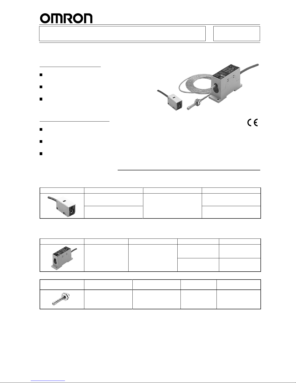
UV Power Monitor F3UV
Monitor the Output of a UV Light Source
through an Optical Fiber Cable
Monitors with Optical Fibers
Head Unit withstands temperatures of up to
300°C.
Easy-to-read digital display of measurement
values.
Harmful UV light converted to visible light before
performing measurements. This feature prevents
deterioration of the Amplifier’s light receiving
element.
Monitors with Built-in Amplifiers
Deterioration due to UV light prevented by
protective structure.
Confirm the output status of the UV light source
with an operation indicator.
Filtering Cover (reduces light intensity by 1/6.5)
also available.
Ordering Information
Monitors with Built-in Amplifiers
Main Unit
Appearance
Intensity range of incident light
Output
Model number
1 to 30 mW/cm
2
Analog voltage output (1 to 5 V)
F3UV-A30
0.2 to 3 mW/cm
2
F3UV-A03
Note:
Does not function as a sensor
.
Monitors with Optical Fibers
Amplifier
Appearance
Connection
method
Outputs T
ransistor type
Model number
Pre-wired cable
•
Judgement output
• Answer-back output
NPN F3UV-XW11
•
Anal
og current or voltage
output
PNP F3UV-XW41
Head Unit
Appearance
W
avelength range of
incident light
Max. temperature
Model number
Remarks
200 to 370 nm
300_C
(Use at temperatures below
the Fiber Unit’
s rated
operating temperature.)
F3UV-HM
Includes two M8 nuts
and one mounting plate.
Page 2
F3UV
F3UV
2
Fiber Units
Compatible
Amplifier Units
Compatible
Head Units
Appearance Max.
temperature
Intensity range of
incident light
(see note)
Model number
Quantity
F3UV-XW11,
F3UV-XW41
F3UV-HM
M4 threads, 2 m
300_C
10 to 300 mW/cm2F32-300
1
M4 threads, 2 m
70_C
10 to 300 mW/cm2F32-70
Note: The
values given are for a standard UV
light source with a central wavelength of 360 nm, measured with a standard illumination meter
(and
for use in combination with the specified Amplifier and Head Unit). The
power range is one for which teaching to 100% is possible.
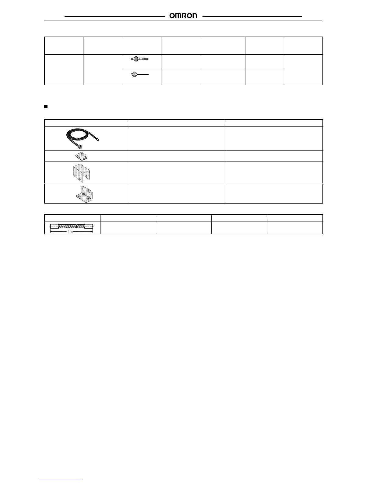
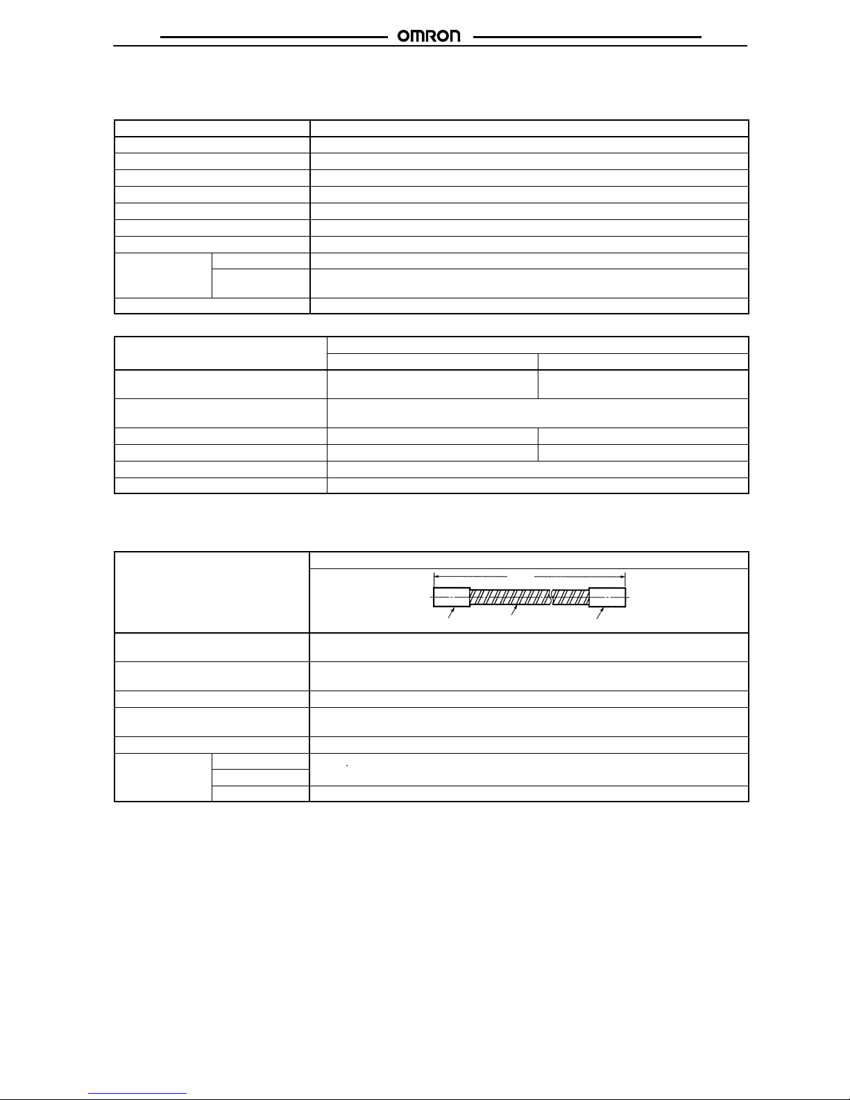
Accessories (Sold Separately)
Accessories for Monitors with Built-in Amplifiers
Appearance Name Model
number
Protective T
ube (Protects the cord.)
F39-CU1M
Protective Cover (Protects the display.) F39-HU2
1/6.5 Filtering Cover
F39-HU1
Mounting Bracket
F39-L9
Accessories for Monitors with Optical Fibers
Appearance Name Model
number
Quantity
Applicable Fiber Units
Protective Tube
(Protects the fiber
.)
F39-FU1M 1 F32-70
Page 3
F3UV
F3UV
3
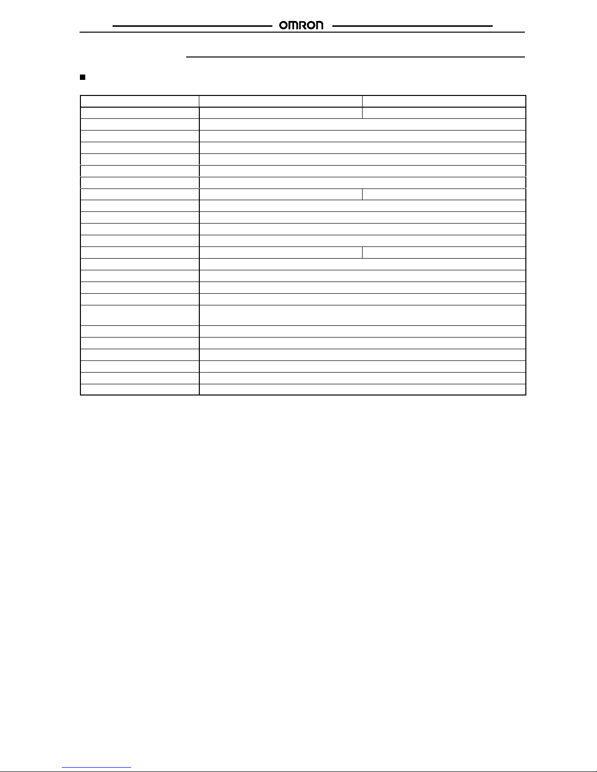
Specifications
Ratings/Characteristics
Monitors with Built-in Amplifiers (Main Unit)
Item F3UV-A30 F3UV-A03
Incident
light power range
1
1 to 30 mW/cm
2
0.2 to 3 mW/cm
2
Incident light wavelength range
200 to 370 nm
Power indicator
Green LED
Operation indicator
Orange LED (lights with an output between 4 and 5 V)
Sensitivity adjustment
One-turn variable adjuster
Power supply voltage
12 to 24 VDC
±10%
Current consumption
15 mA max.
Response time
2
300 ms max. 400 ms max.
Output
3
1 to 5 V (with an of
fset voltage of 0.2 V min.)
Connection impedance
100 kΩ min.
Repetitive accuracy
±
2% F
.S. max.
T
emperature drift
0.2% of F
.S./°C max.
Ambient operating illumination4Fluorescent light 1,000 lx max.
Fluorescent light 500 lx max.
Ambient temperature
Operating: –10° to 70°CStorage: –25° to 80
°C
Ambient humidity
Operating:
35% to 85%
Insulation resistance
20 MΩ min. (at 500 VDC)
Dielectric strength
1,000 V AC 50/60 Hz for 1 min
V
ibration resistance
10 to 150 Hz, 0.1-mm amplitude in X, Y
, and Z directions
(8 minutes of vibration × 10 repetitions= total time 80 minutes)
Shock resistance
150 m/s2 three times each in the ±X, ±Y, and ±Z directions
Degree of protection
Conforms to IEC IP30
Connection method
Pre-wired cable with a standard length of 2 m
W
eight (packed)
78 g
Material Casing: Die-cast zinc
Window: Synthetic quartz glass
Accessories
Operation Manual
Note: 1.
Using a standard UV light source and UV illumination meter in a power range for which analog output can be set to 5 V
.
2.
The response time is the rise time of the output signal to 10 to 90%.
3. An
output voltage up to 6 V can be output. Adjust the sensitivity so
that the output is less than 5 V
. The output is 0.2 to 1 V when there
is
no incident UV light.
4.
This value is the illumination at the receiver window maintaining an of
fset voltage of 1 V max. with the fluorescent light.
Page 4
F3UV
F3UV
4
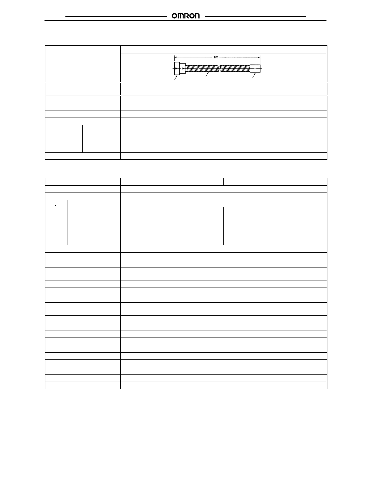
Accessories (Sold Separately)
Protective Tube (Protects the Cord.)
Item
F39-CU1M
Head connector
Flexible tube
End cap
Ambient
temperature
–40°
to 100°C for operation and storage
(Use within the specified operating temperature range for the Monitor
.)
Ambient humidity
Operating:
35% to 85%
Storage: 35% to 95%
Bending radius
24 ± 5 mm
Max. pulling force
2 N-m max. between the head connector and tube, end cap and tube, or on the tube itself
Crush weight
9.8 N-m max. load on the side of the tube
Material
Head
connector
Nickel-plated brass
End cap
Tube
Stainless (SUS304)
Attachment M2 screws
Monitors with Optical Fibers
Amplifiers
Item
F3UV-XW11 F3UV-XW41
Power
supply voltage
12 to 24 VDC
±10%
Current consumption
75 mA max.
Outputs
Analog output
Current (4 to 20 mA) or voltage (1 to 5 V) (Monitoring mode or integral mode)
p
Judgement output
NPN open collector output, 100 mA max.,
PNP open collector output, 100 mA max.,
Answer-back output
residual voltage 1 V max.
(Monitoring mode or integral mode)
residual voltage 2 V max.
(Monitoring mode or integral mode)
Inputs
Remote teaching
input
ON:
0 V short-circuit (current 1 mA max.)
ON:
Power supply voltage short-circuit or 9 to
24 V (open-circuit current: 3 mA max.)
Reset input
OFF:
Open (open or 9 to 24 V)
(p )
OFF:
Open (open or 1.5 V max.)
Protective circuits
Reversed power supply polarity protection and output short-circuit protection
Response time
1
500 ms max.
Sensitivity setting
T
eaching function
Indicators Power supply/T
eaching indicator (green/red), Operation indicator (orange), 7-segment digital
percentage display (red), 7-segment digital threshold display (red)
Repetitive accuracy
±
2% F
.S. max.
Ambient operating illumination2Fluorescent light 1,000 lx max.
T
emperature drift
±
0.1% of F
.S./°C max.
Ambient temperature
Operating: –25 to 55°C (with no icing or condensation) Storage: –40 to 70°C (with no icing or
condensation)
Ambient humidity
Operating or storage: 35% to 85%
Insulation resistance
20 MΩ min. (at 500 VDC)
Dielectric strength
1,000 V AC 50/60 Hz between the leads and the case
V
ibration resistance
10 to 150 Hz, 0.1-mm amplitude or 15 m/s2 in X, Y
, and Z directions each for 2 hours
Shock resistance
150 m/s2 three times each in the X, Y
, and Z directions
Degree of protection
Conforms to IEC 60529 standards IP30
Connection method
Pre-wired cable with a standard length of 2 m
W
eight (packed)
Approx. 270 g
Material ABS plastic
Accessories
Operation Manual
Note: 1.
The response time is the rise time or fall time of the output signal to 10 to 90%.
2. The
ambient operating illumination is the illumination that changes the analog output +5% F
.S. at 200 lx; it is not the operational limit.
3. An
analog output of up to 6 V (or 24 mA) can be output. The output is 1 V (or 4 mA) when there is no incident UV light.
4. F
.S. stands for full scale. For a current output, full scale is 16 mA (4 to 20 mA). For a voltage output, full scale is 4 V (1 to 5 V).
Page 5
F3UV
F3UV
5
5. Definition
of the luminous energy integral: The physical unit of the luminous energy integral is energy (J:
joules) and this value is
calculated
by multiplying the UV intensity (mV)
by the time of exposure (s), but it is dimensionless when this sensor’s analog output
value
(V) is used for the UV intensity
. The integral is measured with an 1
1 ms sampling time.
Head Unit
Item
F3UV-HM
Incident light wavelength range
200 to 370 nm
T
emperature drift
–0.15%/°C max.
Ambient temperature
Operating or storage: –40° to 300°C (with no icing or condensation)
Ambient humidity
Operating or storage: 35% to 85% (with no icing or condensation)
W
eight (packed)
Approx. 300 g
V
ibration resistance
10 to 55 Hz, 0.75-mm amplitude or 10 m/s
2
Shock resistance
500 m/s
2
Material
Protective casing
Stainless steel (SUS303)
Fluorescent fiber
path
Functional fluoroglass
Accessories
M8 nut and mounting bracket
Fiber Units
Item
Model
F32-300 F32-70
Ambient temperature
(with no icing or condensation)
Operating: –40°
to 300
°C
*1
Storage: –40°
to 1
10°C
Operating: –40°
to 70
°C
Storage: –40°
to 70
°C
Ambient humidity
(with no icing or condensation)
Operating:
35 to 85%
Storage:
35 to 95%
Bending radius
25 mm min. 25 mm min.
Fiber outer sheathing material
SUS
Black polyethylene
Degree of protection
Conforms to IEC IP67
Standard fiber length
2 m
Note:
The maximum temperature is lower near the amplifier unit. See the Dimensions for details.
Accessories (Sold Separately)
Protective Tube (Protects the Fiber
.)
Item
F39-FU1M
1,000
Head connector
Flexible tube
End cap
Ambient
temperature
–40°
to 150°C for operation and storage
(Keep the ambient temperature within the range specified for the fiber within the tube.)
Ambient humidity
Operating:
35 to 85%
Storage:
35 to 95%
Bending radius
30 mm min.
Max. pulling force
1.5 N-m max. between the head connector and tube, 1.5 N-m max. between the end cap and
tube, and 2 N-m on the tube itself
Crush weight
29.4 N-m max. on the tube
Head connector
Nickel-plated brass
End cap
p
Tube
Stainless (SUS304)
Page 6

F3UV
F3UV
6
Engineering Data
Monitors with Built-in Amplifiers
Output Characteristics
F3UV-A30
(Output
characteristics when the output is
set at 5 V for a UV intensity of 30 mW/cm2.)
F3UV-A03
(Output characteristics when the output is
set at 5 V for a UV intensity of 3 mW/cm2.)
Angular Characteristics
F3UV-A30/-A03
F3UV-A30/-A03
and F39-HU1 Cover (Sold Separately)
UV power monitor output (V)
UV intensity (mW/cm2)
Relative sensitivity (%)
Angle (degrees)
X-axis relative sensitivity (%)
Relative sensitivity (%)
Angle
(degrees)
UV power monitor output (V)
UV intensity (mW/cm2)
X-axis relative sensitivity (%)
Y-axis relative
sensitivity (%)
Y-axis relative
sensitivity (%)
Monitors with Optical Fibers
Output Characteristics
F3UV-XWj1
+ F3UV
-HM + F32-300
(Output characteristics when the sensitivity
is
set at 300 mW/cm2.)
Angular Characteristics (Y-direction)
F3UV-HM
The
output variation in the X-direction is less than
±
10% of F
.S. in a full 360_ rotation.
Sensor output (V)
UV intensity (mW/cm2)
Relative value (%)
Angle (degrees)
Sensitivity Characteristics
All
F3UV Models
Intensity (relative)
W
avelength (nm)
Page 7

F3UV
F3UV
7
Nomenclature
Monitors with Built-in Amplifiers
F3UV-A30/-A03
Operation
indicator
(orange)
Power
indicator
(green)
Sensitivity
adjuster VR
Functions
Name
Function
Display
functions
Power indicator
Lit green when power supply
is ON.
Operation indicator
Lit orange when the analog
output is between 4 and 5 V
.
Output
functions
Analog output
Outputs a voltage (1 to 5 V)
proportional to the incident
light. (The of
fset voltage is
0.2 V min.)
Sensitivity adjuster
Sensitivity can be set to the
desired level with this
one-turn adjuster
.
Monitors with Optical Fibers
F3UV-XW11/-XW41
Operation
indicator
Lit orange:
Judgement output ON
Fiber lock
Digital display
Sensitivity setting/threshold up
Light intensity monitor mode (MON)
TEACH:
Sensitivity setting
ADJ:
Threshold adjustment
(Up button)
Light intensity integral mode (ITG)
TEACH:
Stop integration
Zero point setting/threshold down
Light intensity monitor mode (MON)
TEACH:
Zero point setting
ADJ:
Threshold adjustment
(Down button)
Light intensity integral mode (ITG)
TEACH:
Start integration
Measurement/T
eaching indicator
Lit green:Teaching OK
RUN
Flashing red:Teaching error
Lit red:
Start light intensity
integration
Processing mode switch
Light intensity monitor mode
TEACH:
Zero point setting/
sensitivity setting
ADJ:
Threshold adjustment
RUN:
Measure light intensity
Light intensity integral mode
TEACH:
Start/stop integration
RUN (ADJ):
Light intensity integral
Output selection switch
IOUT:
Current output (4 to 20 mA)
VOUT: V
oltage output (1 to 5 V)
Operation mode switch
MON:
Light intensity monitor mode
ITG:
Light intensity integral mode
Page 8

F3UV
F3UV
8
Functions
Name
Function
Indicator functions
Measurement/
teaching
indicator
•
Lit green:
T
eaching OK
RUN
•
Flashing red:Teaching error
•
Lit red:
Start light intensity
integration
Operation
indicator
•
Lit orange:
Judgement output ON
Digital display
• Percentage display when operating in
light
intensity monitor mode
HI: Greater than 124%
LO: Less than 0%
Output functions
Analog output
(switchable)
• Outputs
a current (4 to 20 mA) or voltage
(1 to 5 V) that is proportional to the
incident
light intensity
.
Select
current or voltage output with
the
output selection switch.
Judgement
output
• ON when the incident light intensity is
below
the set threshold value.
• OFF when the incident light intensity is
above
the set threshold value.
(Includes a short-circuit protection function.)
Answer-back
output
• A one pulse output (1 sec) is generated
when remote teaching has been completed
normally
.
Input functions
Reset input
• This trigger signal starts integration
when
the Unit is
in integral mode and the
processing
mode is set to “RUN”.
Remote
teaching input
• When the Unit is in monitor mode or
integral mode, teaching is performed
when
a pulse signal is input here.
Threshold setting
function (monitor
mode only)
• The
desired
threshold value can be set
by pressing the Up and Down buttons.
(The digital display will change in 1%
increments
when the value is set.)
Sensitivity setting function (monitor mode only)
Zero point
setting
• Sets
the zero point reference when
the
UV
light source is OFF
.
After teaching, the digital display will
read
“0%”.
Sensitivity
setting
• Sets the initial sensitvity when the UV
light source is ON.
After teaching, the digital display will
read
“100%”.
Max. sensitivity
setting
• Sets the sensor sensitivity to the
maximum sensitivity.
Min. sensitivity
setting
• Sets the sensor sensitivity to the
minimum sensitivity.
Light intensity
monitor function
(Part of the
current/voltage
output switching
function.)
• Displays the digital (%) value
corresponding to the incident light
intensity and outputs the analog
and
judgement outputs.
Light intensity
integral function
(Part of the
current/voltage
output switching
function.)
• Calculates the light intensity integral
value
(I) from the incident light intensity
(P) and time (T) using the following
equation:
I = P × T
.
Also outputs the integral’s analog
output
simultaneously and displays
the
digital
(%) value. (Output ON at 100%.)
Page 9

F3UV
F3UV
9
Operation
I/O Circuit Configuration
Monitors with Built-in Amplifiers
Monitors with Optical Fibers
Main
Brown
Black
Power supply
(12 to 24 VDC)
Output (1 to 5 V)
Power Operation
Power
(green)
Operation
(orange)
Display
Reset input
Remote teaching input
Answer-back
output
Judgement
output
Controller,
etc.
Shield
Black
Load
Load
Brown
12 to 24 VDC
Analog output
0 V
Gray
Internal
circuit
F3UV-XW11 (NPN Output)
Purple
Pink
Blue
White
Main
circuit
Black
Blue
Output (1 to 5 V)
0 V
Sensitivity adjuster
Measurement/
teaching
(green/red)
Operation
(orange)
Display
Reset input
Remote teaching
input
Answer-back
output
Judgement
output
Shield
White
Black
Load
Load
Brown
12 to 24 VDC
Analog
output
0 V
Gray
F3UV-XW41 (PNP Output)
Purple
Pink
Blue
Controller,
etc.
Analog GND
Internal
circuit
Monitors with Built-in Amplifiers
Analog Indications such as Voltage or Current Signals
F3UV-A30/-A03
UV Power Monitor
Black
Blue
K3NX-VD2A-T1
+–
Brown
Page 10

F3UV
F3UV
10
Dimensions
Note: All
units are in millimeters unless otherwise indicated.
Monitors with Built-in Amplifiers
Main Units
F3UV-A30/-A03
Light receiving window
Mounting holes (3.5 dia.)
7.4 dia.
4 dia.
9.5 dia.
Protective cover screw
hole (M2, depth 6)
Power/Operation
indicators
Sensitivity adjuster
Two, M3
Mounting Hole Dimensions
Accessories (Sold Separately)
Protective Tube (Protects Cord.)
F39-CU1M
End Cap (Note 1)
5 dia.
Two, M2
7 dia.
Tube (Note 2)
Head Connector (Note 1)
15 dia.
9.75 dia.
12 dia.
15 dia.
7 dia.
Tube internal
diameter: 5
8.5 dia.
Hex head
set screws
Note: 1. Material:
C3504 (nickel-plated brass)
2. Material:
Stainless steel (SUS304)
3.
M2 securing screws are included.
Installed Protective T
ube
Protective Cover (Protects Display.)
F39-HU2
1/6.5 Filtering Cover
F39-HU1
Material: Stainless steel (SUS304-CSP)
t = 0.2
Material: Stainless steel (SUS304-CSP)
t = 0.2
Installed Protective Cover
Installed 1/6.5 Filtering Cover
Two light receiving windows
2.5 dia.
Two, dia. 1
Two, 3.5 dia.
Optical
axis
F39-L9 Mounting Bracket (sold separately)
Optical axis
Page 11

F3UV
F3UV
11
Mounting Bracket
F39-L9
Material: Stainless steel (SUS304-CP)
t = 0.2
Optical
axis
Optical axis
Optical axis
Monitors with Optical Fibers
Main Units
Amplifier
F3UV-XW11/-XW41
Fiber insertion opening
Measurement/teaching
indicator (green/red)
Operation indicator (orange)
RUN/ADJ/TEACH mode switch
Sensitivity setting/threshold value up button
Zero-point setting/threshold value up button
Monitor/Integral mode switch
Current/Voltage output switch
7-segment display
Fiber lock button
Vinyl-insulated round cable 5.8 dia., 7 conductors
(Conductor cross sectional area: 0.2 mm
2
, diameter
of insulator: 1.1 mm) Standard length 2 m
9.9 dia.
Two, M4
Mounting
Hole Dimensions
Page 12

F3UV
F3UV
12
Base Unit
F3UV-HM
Fiber Unit
F32-300
Fiber Unit
F32-70 (Cuttable)
Detection surface
Lock washer Lock nuts (2)
M8 ×
1
6 dia.
15 dia.
5 dia.
M2.6
× 0.45
Hex nuts (2)
Lock washers (2)
Detection head*
1
M4 ×
0.7
Flexible tube, 2.8 dia. (Stainless)
Hex fastener
Sleeve
1 dia.
4 dia.
4 dia.
5 dia.
Note: The max. temperature is
300_C in section A and
110_C in section B, which
connects
to the Main Unit.
The
part of section
B that is
actually inserted into the
Main Unit must remain within the Main Unit’s rated
operating temperature
range.
Material:
Stainless steel (SUS303)
*1: Material: Stainless steel (SUS303)
1 dia.
M2.6
× 0.45
Hex nuts (2)
Lock washers (2)
Detection head*
M4 ×
0.7
Optical fiber, 2.2 dia.
*Material: Nickel-plated brass
Note:
The “cuttable” Fiber Units can be cut to length. Units that are not marked “cuttable” cannot be cut to length.
Accessories (Sold Separately)
Protective Tube (Protects the Fiber.)
F32-FU1M
M4
× 0.7,
depth 4
Head Connector
*1
End Cap
*1
Tube
*2
(5.6 dia.)
7 dia.
4 dia.
Note: 1. Material: Nickel-plated brass
2. Material:
Stainless steel
(SUS304)
Page 13

F3UV
F3UV
13
Precautions
Be
sure to observe the precautions listed here. These precautions
are
essential for safe operation.
• Do
not
use these Units in locations with flammable or explosive
gases.
• Do
not use these Units in water
.
• Do not attempt to disassemble, repair, or improve these
products.
• Always use a power supply voltage that is within the specified
operating
range. Do not use with an AC power supply
.
• Be sure that wiring is correct, such as the polarity of the power
supply leads.
•
Connect loads properly
.
•
Do not short-circuit the load’
s terminals.
• Do not mount the Amplifier Unit in a location where it will be
exposed
to UV light.
Precautions Common to the F3UV-series
Wiring
Connections
Make
sure that the power supply voltage is below the maximum volt
-
age
before turning the power ON.
Be sure that the terminal polarity and wiring are correct.
Never
share a conduit that is used for high-voltage or power lines.
Use extension cords with a minimum thickness of 0.3 mm2, less
than
5 m long, and check operation before using.
Power Supply
When using a commercial switching regulator, ground the FG
(frame
ground) and G
(ground) terminals. Output signal noise will be
excessive
if the power supply is not grounded.
After
turning on the power supply
, wait for at least one second
until
consistent
detections can be performed before using the Monitor
. If
separate
power supplies are used for
the F3UV and connected de
-
vices,
always turn ON the F3UV’
s power supply first.
Installation and Operation
Installation
UV
light is harmful, so be sure to turn OFF the UV light source before
installing
the F3UV
.
Sensitivity Setting
The
analog output value will change due to temperature drift. If the
temperature is rising, wait for the temperature to stabilize before
setting the sensitivity.
Precautions for the F3UV-A30/A03
Installation
Installation Torque
T
orque the sensor’s Main Unit screws to 0.49 N-m max.
Precautions Regarding UV Light
The
sensor’s display and
cord are not protected against UV expo
-
sure.
If these parts will be exposed to UV light, protect
them with the
F39-HU2
Protective Cover and F39-CU1M Protective T
ube.
When
UV light will be in the
user’s field of vision or directly contact
the
skin during adjustment, use a shield or other protective device
to
prevent
injury
.
Adjustment
Sensitivity Adjustment
Use
the following procedure to adjust the analog output to 5 V before
initial
operation or after replacing the UV light source.
1. Set up the Sensor and the UV light source to be monitored.
The sensitivity adjuster is factory set to its minimum setting
(all
the way to the left).
2. T
urn ON the UV light source.
3. Check
whether the operation indicator (orange) of the Sensor
is lit. The operation indicator will light if the analog output
value is between 4 and 5 V. If it does not light, adjust in the
following way.
4.
Rough Adjustment
The
operation indicator will light if the analog output value is
between
4 and
5 V
. In this case, proceed to
Fine Adjustment
below. If the operation indicator is not lit, check whether the
operation indicator can be made to light by turning the
sensitivity adjuster. If the operation indicator still does not
light, then the UV intensity is either too high (i.e., exceeds
Sensor specifications, with an analog output value greater
than
5 V), or is too low
. If the UV intensity is too high, make the
operation
indicator light by
either using the F39-HU1 Filtering
Cover (sold separately), or moving the Sensor farther away
from
the UV light source. If the UV intensity is too low
, move
the Sensor closer to the UV light source, until the operation
indicator
lights.
5.
Fine Adjustment
Adjust
the sensitivity adjuster until the analog output value is
5 V. If it not possible to obtain a value of 5 V this way
, then the
distance between the Sensor and the UV light source is
inappropriate. Move the Sensor either closer to, or farther
away
from the UV light source.
Cleaning
Never
use paint thinner or mineral spirits of any kind. If there is de
-
bris
or dust on the light-receiving window
, wipe it of
f with a soft
cloth
or
blow it of
f with a low-pressure air sprayer
.
Precautions for the F3UV-XW11/XW41
Installation
1. Installation Torque
T
orque the sensor’s Main Unit screws to 0.49 N-m max.
2. Using DIN Track
(Installation)
1.
Hook the top of the Unit onto the DIN T
rack.
2.
Snap the bottom of the Unit onto the DIN T
rack.
Note:
Do not reverse steps 1 and 2.
(Removal)
When
removing the Unit from the DIN T
rack, pull the
mount
-
ing
hook forward to release it.
Page 14

F3UV
F3UV
14
DIN
Track
Mounting hook
(2)
(1)
Precautions Regarding UV Light
The Amplifier itself is not protected against UV exposure. Do not
install
the Amplifier in
locations where it will be exposed to UV light.
Adjustment
Basic
Operating Procedures
1.
Install the Amplifier Unit.
2.
Connect the Fiber Unit to the Amplifier Unit.
3. T
urn ON the power supply
.
4. Select an operating mode with the operation mode switch.
(Light
intensity monitor mode
or light intensity integral mode)
5. When using the analog output, select current or voltage
output
with the output selection switch.
6. Set the processing mode switch to TEACH and perform the
teaching operation.
•
Light Intensity Monitor Mode
Make
the zero-point setting
when the indicator is not lit and
make
the sensitivity setting when the indicator is lit. (Make
the
sensitivity setting after the temperature has
stabilized.)
• Light
Intensity Integral Mode
Use
the start setting at the start of illumination and the stop
setting when completed. Teaching can be performed by
pressing
the buttons or with codes.
7. When
changing the threshold value in light intensity monitor
mode,
set the processing mode switch to ADJ and adjust the
threshold value. The judgement output will go ON when the
light intensity is below the threshold value. The threshold
value
is set to 50 at the factory
.
8. Set the processing mode switch to RUN to start
measurement. In light intensity integral mode, start
integration
with the Reset input.
Cleaning
Never use paint thinner or mineral spirits of any kind.
Fiber Unit/Base Unit
Installation
Installing
the Head Unit
When
connecting the Head Unit and Fiber Unit, tighten to
a torque of
0.78
N-m max. When installing the
Head Unit, be sure to turn OFF
the
UV light source and check that it is safe to install the Unit.
Head Unit
(F3UV-HM)
M8 nuts
(included)
M4 nut
(included)
Mounting panel
W
ashers (included)
Fiber Unit
(F32-300)
Installing the Fiber Unit and Amplifier Unit
The
quality of the connection between the Fiber Unit and Amplifier
Unit
has a major impact on the operating characteristics, so be sure
to connect these Units securely.
Securing the Fiber Unit
1.
Cutting the Fiber (F32-70 only)
• Insert the fiber into the hole of the cutting tool and set the
tool
at the desired length.
• Press
down on the blade and cut the fiber
. Do not stop when
the
fiber is only partially cut; make one clean cut.
• Once a hole has been used to cut a fiber, do not use that
hole
again. The cut surface may not be clean enough and
the
detection characteristics may be degraded.
2.
Installing the Fiber
With
the lock button in the release position, insert the fiber
into
the
Unit and press the button until you hear a click. This click
is
the sound of the fiber being locked.
Locked position
Release position
3.
Removing the Fiber
Press
the lock
button again. The lock will be released, the lock
button
will pop up, and it will be possible to remove the fiber
.
Do
not force the lock button up by pulling on it. (T
o maintain
the fiber’s characteristics, check whether the lock is out of
place.)
4. Fiber
Insertion Location
When
inserting the Fiber Unit into the Amplifier Unit, always
Page 15

F3UV
F3UV
15
insert the Fiber Unit completely as shown in the following
diagram.
Fiber
Unit
(Example:
F32-300)
Fiber Unit
(Example:
F32-70)
5.
Fiber Unit Installation/Removal Precautions
Install and remove the Fiber Unit only when the ambient
temperature
is between –40 and 40
_C.
6.
Protecting the Fiber Unit
When the outer sheathing of a FIber Unit other than the
F32-300 will be exposed to UV light, protect the fiber by
covering
it with the F39-FU1M Protective T
ube.
Page 16

F3UV
F3UV
16
OMRON Corporation
Industrial
Automation Company
Industrial Sensors Division
Sensing Devices and Components Division H.Q.
Shiokoji Horikawa, Shimogyo-ku,
Kyoto, 600-8530, Japan
Tel: (81)75-344-7068/Fax: (81)75-344-7107
ALL DIMENSIONS SHOWN ARE IN MILLIMETERS.
To
convert millimeters into inches, multiply by 0.03937. T
o convert grams into ounces, multiply by 0.03527.
Cat. No. E315-E1-1 In the interest of product improvement, specifications are subject to change without notice.
Printed
in Japan
0301-1M (0700) (O)
 Loading...