


INSTRUCTION MANUAL
Single Beam Safety
Sensor
F3SS Series
Cat. No. SCEE711-E2-1
Introduction
Thank you for purchasing the F3SS Series Single Beam Safety Sensor.
Always heed the following points when using the F3SS:
• Make sure that personnel operating the F3SS are knowledgeable about the machine on which it is installed
• Read this manual completely and be sure you understand the information provided before attempting to
operate the F3SS
• Keep the manual in a secure and convenient location and refer to it as necessary.
Regulations and Standards
(1) The F3SS has not received the type approval provided by Article 44-2 of the Industrial Safety and Health
Law of Japan. Therefore, it cannot be used in Japan as a safety device for pressing or shearing machines
provided by article 42 of that law.
(2) The F3SS complies with the following regulations and standards.
IEC standard
- IEC 61496-1 (Type 4 ESPE)
- IEC 61496-2 (Type 4 AOPD)
Notice
If you use the F3SS under the condition or environment shown below, be sure to use it by leaving a margin for each rating and function and taking system safety into consideration.
(1) Use of the F3SS under any condition or environment not described in this manual.
(2) Use of the F3SS for devices and facilities requiring special safety (e.g., nuclear control, railway, aerospace,
automobile, combustion facility, medical system, space development, and large-scale amusement machinery).
Precaution on Safety
General conventions for safe use
The following conventions are used for precautionary items in this manual in order to ensure safe and proper
use of the F3SS. Items listed here are critical for safety and must be heeded at all times.
WARNING
Indicates a potentially hazardous situation which, if not avoided, could
result in death or serious injury.
Indicates prohibited actions.
i

Table of Contents
1 Significant Features and Requirements .................................................................................................. 1
1-1 F3SS General Description ..................................................................................................................... 1
1-2 Meeting Full Compliance ....................................................................................................................... 1
1-3 Employer Responsibilities ...................................................................................................................... 1
1-3-1 Additional Requirements ................................................................................................................. 1
2 Theory of Operation ................................................................................................................................... 2
2-1 F3SS System Specifications .................................................................................................................. 2
2-1-1 Technical Specifications* ................................................................................................................. 2
3 Description of Controls ............................................................................................................................. 4
3-1 Access to Controls ................................................................................................................................. 4
3-1-1 Emitter Indicator Lights .................................................................................................................... 4
3-1-2 Receiver Indicator Lights ................................................................................................................. 4
3-1-3 Receiver Operating Mode Switch .................................................................................................... 5
3-1-4 Emitter and Receiver Code Switches .............................................................................................. 5
3-1-5 Safety Outputs ................................................................................................................................. 5
3-1-6 Remote Start Switch (optional) ........................................................................................................ 5
4 Installation .................................................................................................................................................. 6
4-1 User Responsibility ................................................................................................................................ 6
4-1-1 User Responsibility .......................................................................................................................... 6
4-2 Installation Procedure ............................................................................................................................ 6
4-3 Perimeter Guarding Special Requirements ........................................................................................... 6
4-4 Minimum Safe Mounting Distance and Mounting Height ....................................................................... 7
4-5 Switch Settings ...................................................................................................................................... 8
4-5-1 Emitter and Receiver Code Switches .............................................................................................. 8
4-5-2 Operating Mode Switches ............................................................................................................... 8
4-6 Electrical Connections ......................................................................................................................... 12
4-6-1 Emitter Electrical Connections ....................................................................................................... 12
4-6-2 Receiver Electrical and Control Connections ................................................................................ 12
4-6-3 Long cable length installation for Receiver .................................................................................... 12
4-6-4 Safety Earth Connections .............................................................................................................. 13
4-7 Machine Control Circuit Connections .................................................................................................. 13
4-7-1 Solid-state Output Connection ....................................................................................................... 13
4-7-2 Connection Method ....................................................................................................................... 13
4-8 Physical Mounting ................................................................................................................................ 17
4-8-1 Installation of Multiple F3SS Units ................................................................................................. 17
4-8-2 Reflective Surface Interference ..................................................................................................... 17
4-8-3 Bracket Mounting Points ................................................................................................................ 19
4-8-4 Alignment ....................................................................................................................................... 19
5 Troubleshooting and Maintenance ......................................................................................................... 20
5-1 Troubleshooting ................................................................................................................................... 20
5-2 Maintenance ........................................................................................................................................ 20
6 Accessories .............................................................................................................................................. 21
6-1 Accessories ......................................................................................................................................... 21
Appendix A —Test Procedures ...................................................................................................
A-1 Tests To Perform ................................................................................................................................. 22
Appendix B —Checkout Procedure .......................................................................................................... 24
B-1 Checkout Procedure Log ..................................................................................................................... 24
.............. 22
ii


1-1 F3SS General Description
1 Significant Features and Requirements
1 Significant Features and Requirements
1-1 F3SS General Description
The F3SS single safety light beam is a general purpose presence sensing device. The F3SS is designed specifically for whole body detection and must not be used for point of operation guarding.
1-2 Meeting Full Compliance
Whether a specific machine application and F3SS installation meets full compliance with safety regulations depends on several items, including the proper application, installation, maintenance and operation of the F3SS.
These items are the sole responsibility of the purchaser, installer and employer.
1-3 Employer Responsibilities
The employer is also responsible for the selection and training of the personnel necessary to properly install,
operate and maintain the machine and its safeguarding systems. The F3SS must only be installed, checked out
and maintained by a qualified person, as “a person or persons who, by possession of a recognized degree or
certificate of professional training, or who, by extensive knowledge, training or experience, has successfully
demonstrated the ability to solve problems relating to the subject matter and work.” (ANSI B30.2-1983)
The machine operator must notify management if the machine, tooling or safety devices are not operating properly. Never use the machine if it is not in proper working order.
1-3-1 Additional Requirements
The following is a list of additional requirements you must meet before using the F3SS safety light beam.
• Never use the F3SS for point of operation guarding.
• The machine on which the F3SS is installed must be capable of stopping motion anywhere in its stroke or
cycle. Do not use the F3SS on a power press with a full-revolution clutch. This product cannot be used in
Japan as a safety device for pressing or shearing machines provided by article 42 of that law.
• The F3SS does not offer protection from flying objects.
• Do not use the F3SS on any device with inconsistent stopping time or inadequate control devices or
mechanisms.
• Do not use the F3SS where the environment, such as severe smoke, particulate matter, or corrosive
chemicals, may degrade the efficiency of the F3SS.
• When the F3SS is utilized as a safety device, the employer has the responsibility to ensure that all applicable
national, federal, state and local rules, codes and regulations are satisfied.
• All safety-related machine control circuit elements, including pneumatic, electric or hydraulic controls must
be control reliable. Control reliable is defined as: “...the device, system or interface shall be designed,
constructed and installed such that a single component failure within the device, interface or system shall
not prevent normal stopping action from taking place, but shall prevent a successive machine cycle...”
• Additional guarding such as mechanical guards may be required if the F3SS does not protect all points of
entry into the hazardous area.
• All brakes and other stopping mechanisms and controls must be in proper working order. If the machine stop
mechanisms and associated controls are not working properly, the machine may not stop safely even though
the F3SS is functioning properly.
• The test procedures must be performed after any maintenance is performed on the machine controls or the
F3SS. The test procedure (Appendix A) is contained in this manual. The user must perform (at least every
three months, more often with continuous use) the preventive maintenance procedures recommended in this
manual.
• Do not perform any test or repairs other than those outlined in this manual. All electrical wiring must be
installed in accordance with local electrical codes and regulations.
• The user must follow all procedures in this manual for proper operation of the F3SS.
• The enforcement of these requirements is beyond OMRON’s control. The employer has the sole
responsibility to follow the preceding requirements and any other procedures, conditions and requirements
specific to his machinery.
1

2 Theory of Operation
2-1 F3SS System Specifications
2 Theory of Operation
2-1 F3SS System Specifications
The F3SS is a long-range, single-beam infrared safety control designed for perimeter and access guarding. Interruption of the beam sends a stop signal to the guarded machine. A “redundant” microprocessor design combined with extensive fault mode and effects analysis provides safe, control reliable operation.
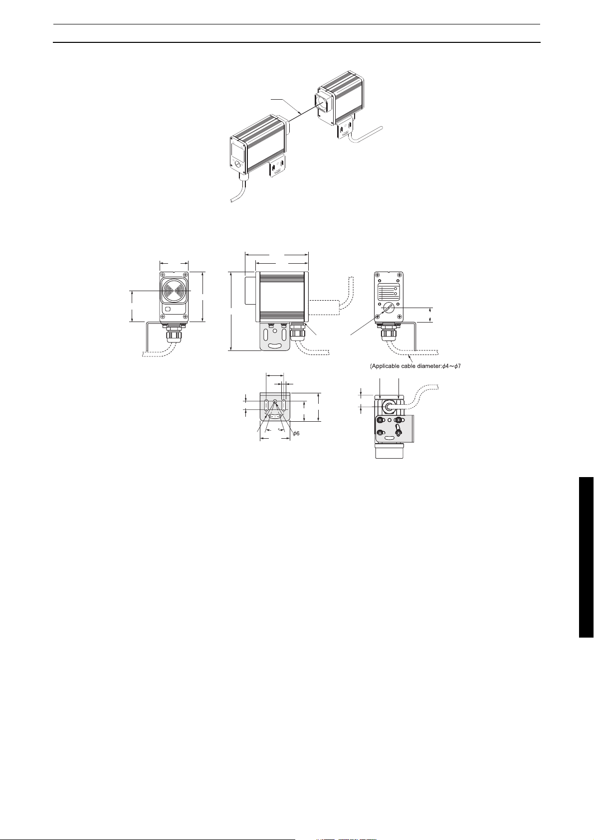
A F3SS system consists of one emitter and one receiver. No interconnecting cables or separate control enclosure are required. Maximum distance between emitter and receiver is 60 m(200 ft.).
2-1-1 Technical Specifications*
Operating range 0.3-60 m
Number of beams 1 (single beam)
Beam diameter 31 mm
Minimum object resolution Opaque object, ø31 mm or more
Orientation angle
Light source (emission waveform) Infrared LED (880 nm)
Power supply voltage
Rise time after power ON Within 4 seconds
Current consumption Emitter: 170 mA max.
Operating mode Either of the following modes is selectable by the select switch of the
Control output PNP transistor output x 2 outputs, load current 250 mA or less (resid-
Protective circuit Output load is short-circuit protected, inverted power supply connec-
Response time (ON-->OFF) 35 ms or shorter
Ambient temperature
Ambient humidity 35-95% RH at operation and storage (non-condensing)
Resistance to vibration Malfunction and durability: 10-55 Hz, double amplitude 0.7 mm, X, Y
Shock resistance
Protective structure IEC60529 IP65
Connecting method Connect by terminal block on internal board.
Weight (packaged) 2.5kg
Material Case Aluminum
Cap Aluminum
Accessories Mounting hardware, operating instructions, caps for unused conduits
Applicable standard IEC(EN)61496-1 TYPE4 ESPE *1
Emitter and receiver: ±2.5
m (IEC61496-2).
24 VDC
Receiver: 800 mA max.
receiver:
Auto start
Start interlock
Start/restart interlock
ual voltage 1V or less) (excluding voltage drop due to cable extension), ON at light ON.
tion is protected.
0-55
and Z-direction, 20 sweeps
Malfunction and durability: 100 m/s
IEC61496-2 TYPE4 AOPD *2
±10%, ripple (p-p) 5% or less
°C at operation and storage (non-icing, non-condensing)
°maximum, at operating range longer than 3
2
, X, Y and Z-direction, 1000 times
*1. ESPE(Electro-Sensitive Protective Equipment)
*2. AOPD(Active Opto-electronic Protective Devices)
*Specifications subject to change without notice.
2
2-1 F3SS System Specifications
R
0.5
Groove fo
ut
50.8
2 Theory of Operation
SENSING BEAM
EMITTE
RECEIVER
Figure 2-1 Typical Installation
111.8
93.0
55.24
88.9
139.7
Conduit
PG 9
32.4
35
47.6
6.9
2
35.1
.9
50.8
Mounting hardware
13.0
27.3
Figure 2-2 System Drawing
Figure 2-3 Indication position
Figure 2-4 Switch and Terminal block position
25.4
)
r T-n
3
3 Description of Controls
3-1 Access to Controls
3 Description of Controls
3-1 Access to Controls
All switches and terminal blocks located on internal printed circuit assemblies (PCA) are accessed by removing
the four captive screws which hold the emitter and receiver rear covers in place. For ease of access the PCA
will slide approximately 1/2 way out of the housing. A stop is installed to keep the PCA from sliding completely
out of the housing.
On emitter and receiver models two ports, threaded PG9 are provided for entry of cables. One is on the bottom
surface and one is on the rear cover. A threaded plug is provided for the unused port.
3-1-1 Emitter Indicator Lights
The front panel of the emitter has two indicator lights:
Amber Indicates that the emitter has powered-up correctly.
Red Indicates that a emitter fault (DIP switch set to invalid setting or changed after power-up)
was detected after application of power.
3-1-2 Receiver Indicator Lights
The front panel of the receiver has four indicator lights:
Green Run. The infrared beam is not interrupted.
Red Stop. The infrared beam has been interrupted or is out of alignment.
Yellow Interlock. The system has interlocked. The fault must be corrected before the system can be
reset.
Amber Signal Strength. For use as an alignment aid. Status interpreted as follows:
Steady on: Strong Signal Strength
Flashing: Weak Signal Strength
Off: Out of Alignment or Beam Blocked.
A flashing signal strength indicator may be acceptable at long range or when using mirrors
in an installation.
The rear panel of the receiver has two diagnostic indicator lights labeled F1 and F2. These lights flash at different
rates to provide troubleshooting assistance. The faults indicated by the number of flashes are detailed in the
troubleshooting section of this manual.
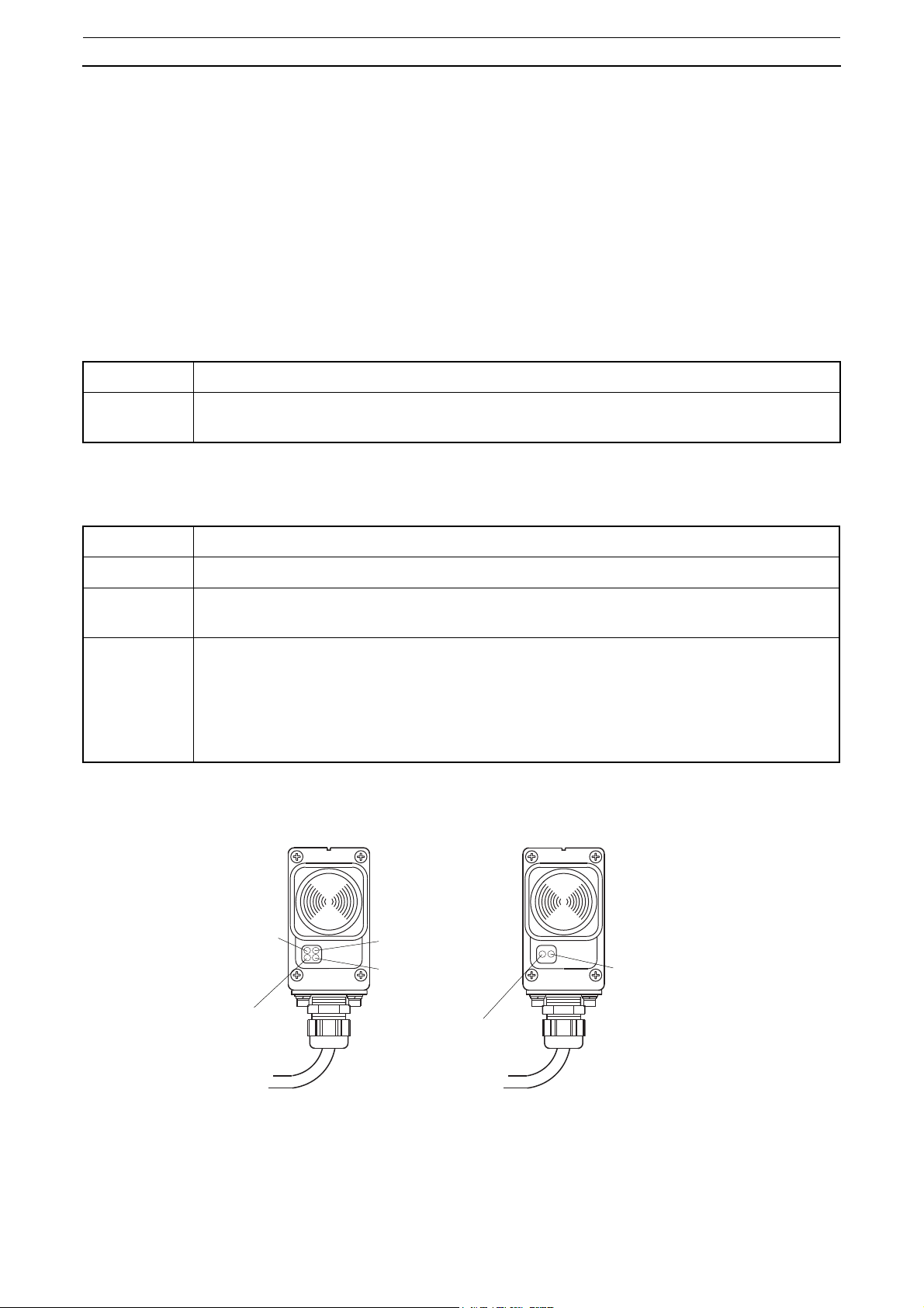
Interlock
indicator (Yellow)
OFF-state indicator (Red)
Receiving level
indicator (Amber)
Fault indicator (Red)
ON-state indicator (Green)
Receiver
Emitting (=Operating)
indicator (Amber)
Emitter
Figure 3-1
4

3-1 Access to Controls
3 Description of Controls
3-1-3 Receiver Operating Mode Switch
The system can be set for three possible operating modes:
Start/Restart Interlock Upon power-up a start signal (press & release) is required before system can
enter normal operation. If the infrared beam is obstructed, the output relays will
not reset after a beam obstruction is removed until a start signal has been given
to the receiver. This is the mode most often used for perimeter guarding.
Start Interlock Mode Upon power-up a start signal (press & release) is required before system can
enter normal operation. If the infrared beam is obstructed, the output relays will
reset after a beam obstruction is removed, without requiring a start signal.
Automatic Restart Upon power-up the system will enter normal operation. If the infrared beam is
obstructed, the output relays will reset after a beam obstruction is removed, without requiring a start signal.
Details on operating mode set-up are given in the installation section.
3-1-4 Emitter and Receiver Code Switches
The infrared beam from a F3SS emitter must be set for one of four possible codes. The beam is coded to avoid
cross talk from adjacent units and improve immunity to weld flash and sources of ambient light.
Both the emitter and receiver must be set to the same code in order to “talk” with one another. See installation
section for switch setting details.
3-1-5 Safety Outputs
Two safety solid-state relay outputs are provided. Each output sources (PNP) up to 0.25 Amps at 24VDC.(voltage level varies with supply voltage)
3-1-6 Remote Start Switch (optional)
The Start switch is a normally closed, momentary switch that connects between the Start and Start Return terminals of the receiver terminal block. A valid Start signal is a press and release of the switch. The receiver start
circuit applies about 5mA DC current through the switch contacts and a pulse of approximately 100mA, 20mS
when the switch contacts are initially closed.
- In Automatic Start mode a start switch is not required and the terminals can be left open.
- In Start Interlock and Start/Restart Interlock modes the start switch is required to exit Interlock. In all
modes, a Start switch can be used to reset an interlock caused by a fault, once the fault is removed.
5
 Loading...