

Omron F3SL-A0871P30, F3SL-A0351P30, F3SL-A1046P30, F3SL-A1219P30, F3SL-A1394P30 Instruction Manual
...Page 1

Safety Light Curtain
INSTRUCTION MANUAL
Cat. No. SCEE712-E2-1
INSTRUCTION MANUAL
Safety Light Curtain
F3SL Series
Cat. No. SCEE712-E2-1
Page 2

Page 3

i
Introduction
Thank you for purchasing the F3SL Series Safety Light Curtain.
Always heed the following points when using the F3SL:
• Make sure that personnel operating the F3SL are knowledgeable about the machine on which it is installed
• Read this manual completely and be sure you understand the information provided before attempting to
operate the F3SL
• Keep the manual in a secure and convenient location and refer to it as necessary.
(1) The F3SL has not received the type approval provided by Article 44-2 of the Industrial Safety and Health
Law of Japan. Therefore, it cannot be used in Japan as a safety device for pressing or shearing machines
provided by article 42 of that law.
(2) F3SL an equipment conforming to ESPE (Electro Sensitive Protective Equipment) specified in the 1st
Clause of Safety Component, Annex IV B in the EU (European Union) Machinery Directive. F3SL also conforms to the following overseas regulations and standards.
EU regulations and technical standards:
- Machinery Directive: No. 98/37/EC
- EMC Directive: No. 89/336/EEC
- EN 61496-1(06/98) (Type4 ESPE)
IEC standard
- IEC 61496-2(11/97) (Type 4 AOPD)
(3) F3SL has been received the following certification from EU authorized institutions.
"EC Type Approval (TYPE 4 ESPE)" in accordance with the Machinery Directive, from TÜV Rheinland.
If you use the F3SL under the condition or environment shown below, be sure to use it by leaving a margin for each rating and function and taking system safety into consideration.
(1) Use of the F3SL under any condition or environment not described in this manual.
(2) Use of the F3SL for devices and facilities requiring special safety (e.g., nuclear control, railway, aerospace,
automobile, combustion facility, medical system, space development, and large-scale amusement machinery).
General conventions for safe use
The following conventions are used for precautionary items in this manual in order to ensure safe and proper
use of the F3SL. Items listed here are critical for safety and must be heeded at all times.
Regulations and Standards
Notice
Precaution on Safety
WARNING
Indicates a potentially hazardous situation which, if not avoided, could
result in death or serious injury.
Indicates prohibited actions.
Page 4

ii
WARNING
A F3SL should only be installed, checked out and maintained by a qualified person. It is important that the
user be familiar with the installation requirements, safe mounting distance, controls and features before
using the F3SL.
If the F3SL is used as a safety device, the user has the responsibility to insure that applicable national, federal and local safety rules, codes and regulations are satisfied. In addition, the user should insure that all
machine operators, maintenance personnel, electricians, supervisors, etc. are familiar with and understand
all instructions regarding the use of the F3SL, the machinery on which it is installed and the appropriate
safety regulations.
Perimeter guarding installations must not allow a machine or robot to restart automatically. Use a start switch
placed outside and within view of the hazardous area.
Disconnect power before removing end caps.
Use of Exact Channel Select and/or Floating Blanking will make the F3SL system less sensitive to objects in
the detection zone. Improper use of either can result in severe injury to personnel. Exact Channel Select
may require a hard barrier guard (see “9-2-1 Additional Guarding” on page 9-2-1 Additional Guarding 19),
Exact Channel Select or Floating Blanking may require an increase in the safety distance. Read the following section carefully.
Using Exact Channel Select with Floating Blanking is an advanced feature. All situations which may occur to
the F3SL system detection zone must be carefully considered. The F3SL system may be less sensitive to
objects in the detection zone. The safety distance must be increased. Failure to do so may cause serious
injury.
To prevent a hand or other objects to enter the channel-selected part, provide a physical guard such as a
fence.
This product is designed for use on a 24 VDC, negative ground (protective earth) electrical system only.
Never connect the F3SL to a positive ground (protective earth) system. With a positive ground (protective
earth) wiring scheme, certain simultaneous shorts of both safety outputs may not be detected and the
guarded machine may not stop resulting is severe operator injury.
Never install a F3SL system without regard to the safety distance. If the F3SL system is mounted too close
to the point of operation hazard, the machine may not stop in time to prevent an operator injury.
Install the F3SL system so as not to be affected by the reflection from the reflective surface. Failure to do so
may cause the system undetectable, resulting in severe operator injury.
Never use only a single safety output to control the machine. Should this single output fail, the machine may
not stop, resulting in severe operator injury. The machine must be connected using both safety outputs.
The tests outlined in the Test Procedure in Appendix B must be performed at installation, according to the
employer’s regular inspection program and after any maintenance, tooling change, set up, adjustment, or
modification to the F3SL system or the guarded machine. Where a guarded machine is used by multiple
operators or shifts, it is suggested that the test procedure be performed at each shift or operation change.
Testing ensures that the light curtain and the machine control system work properly to stop the machine.
Failure to test properly could result in serious injury to personnel.
Page 5

iii
Table of Contents
1 Important Safety Warnings ....................................................................................................................... 1
2 Theory of Operation ................................................................................................................................... 2
2-1 F3SL System Specifications .................................................................................................................. 2
2-2 Technical Specifications ........................................................................................................................ 2
3 System Components and Indicators ........................................................................................................ 4
4 System Operation ...................................................................................................................................... 6
4-1 Operating States .................................................................................................................................... 6
4-1-1 Machine Run ................................................................................................................................... 6
4-1-2 Machine Stop ................................................................................................................................... 6
4-1-3 Interlock ........................................................................................................................................... 6
4-1-4 Alarm ............................................................................................................................................... 6
4-2 Operating Modes ................................................................................................................................... 6
4-2-1 Automatic Start ................................................................................................................................ 6
4-2-2 Start Interlock .................................................................................................................................. 6
4-2-3 Start/Restart Interlock ...................................................................................................................... 6
4-3 Operating Mode Selection ..................................................................................................................... 7
5 Detection Options ...................................................................................................................................... 8
5-1 Exact Channel Select (ECS) .................................................................................................................. 8
5-2 Floating Blanking ................................................................................................................................... 8
5-3 Using Exact Channel Select with Floating Blanking .............................................................................. 9
5-3-1 The Effect of Exact Channel Select and Floating Blanking on Minimum Object Resolution ......... 10
5-4 Activating and Programming Exact Channel Select ............................................................................ 10
5-5 Activating Floating Blanking ................................................................................................................. 11
6 DIAGNOSTIC AND TEST FEATURES ..................................................................................................... 12
6-1 Upper Most/ Lower Most Beam Indicators ........................................................................................... 12
6-2 Synchronization Beam ......................................................................................................................... 12
6-3 Machine Primary Control Element (MPCE) Monitoring ........................................................................ 12
6-3-1 Activating and Deactivating MPCE Monitoring .............................................................................. 12
7 Outputs ..................................................................................................................................................... 13
7-1 Safety Outputs ..................................................................................................................................... 13
7-2 Auxiliary Output ................................................................................................................................... 13
8 Safe Mounting Distance .......................................................................................................................... 14
8-1 European Safety Distance Formulas ................................................................................................... 14
8-1-1 Safety Distance Formula for Systems with a Minimum Object Resolution of 40 mm or Less .......................... 14
8-1-2 Safety Distance Formula for Systems with a Minimum Object Resolution Greater Than 40 mm ..................... 15
8-1-3 Factors Affecting the Safety Distance Formula ............................................................................. 15
8-2 US Safe Distance Formulas ................................................................................................................ 15
9 Installation ................................................................................................................................................ 17
9-1 Reflective Surface Interference ........................................................................................................... 17
9-2 General Considerations ....................................................................................................................... 19
9-2-1 Additional Guarding ....................................................................................................................... 19
9-2-2 Installation of Multiple Systems ..................................................................................................... 19
9-2-3 Access to Configuration Switches ................................................................................................. 20
9-2-4 Detection Zone .............................................................................................................................. 20
9-2-5 Alignment ....................................................................................................................................... 20
9-2-6 Cable Assemblies .......................................................................................................................... 21
9-2-7 Input Power Requirements/Connections ....................................................................................... 21
9-2-8 Special Requirements for Perimeter Guarding .............................................................................. 21
9-2-9 Marking Minimum Object Resolution ............................................................................................. 21
9-2-10 Presence Sensing Device Initiation ............................................................................................. 21
Page 6

iv
10 Connecting To The Machine Control Circuit ....................................................................................... 22
110-1 Connecting Via Two Force-Guided Relays ...................................................................................... 22
10-2 Connection with OMRON safety relay unit Model G9SA ................................................................... 23
11 Checkout and Test Procedures ............................................................................................................ 24
11-1 Checkout Procedure .......................................................................................................................... 24
11-2 Test Procedure .................................................................................................................................. 24
11-3 Using the Test Object ........................................................................................................................ 24
12 Cleaning .................................................................................................................................................. 24
13 Dimensional Drawings and Patents ..................................................................................................... 25
13-1 Dimensional Drawings ....................................................................................................................... 25
13-2 Patents ............................................................................................................................................... 25
14 Troubleshooting ..................................................................................................................................... 26
14-1 Receiver Endcap Indicator Lights ...................................................................................................... 26
14-1-1 Receiver Troubleshooting ............................................................................................................ 26
14-2 Emitter Endcap Indicator Light ........................................................................................................... 26
14-2-1 Troubleshooting the Emitter ........................................................................................................ 26
Appendix A —Checkout Procedure .......................................................................................................... 27
A-1 Checkout Procedure Log ..................................................................................................................... 27
Appendix B —Test Procedure ................................................................................................................... 28
B-1 Test Procedure Log ............................................................................................................................. 28
Page 7

1 Important Safety Warnings
1
1 Important Safety Warnings
A F3SL system is a general purpose presence sensing device designed to guard personnel working around
moving machinery.
Whether a specific machine application and F3SL system installation complies with safety regulations depends
on the proper application, installation, maintenance and operation of the F3SL system. These items are the responsibility of the purchaser, installer and employer.
The employer is responsible for the selection and training of personnel to properly install, operate, and maintain
the machine and its safeguarding systems. A F3SL system should only be installed, verified and maintained by
a qualified person.A qualified person is defined as "a person or persons who, by possession of a recognized
degree or certificate of professional training, or who, by extensive knowledge, training or experience, has successfully demonstrated the ability to solve problems relating to the subject matter and work." (ANSI B30.2-1983)
To use a F3SL system the following requirements must be met:
• The guarded machine
must be able to stop anywhere in its cycle. Do not use a safety light curtain on a press
with a full-revolution clutch.
• The guarded machine must not present a hazard from flying parts.
• The guarded machine must have a consistent stopping time and adequate control mechanisms.
• Severe smoke, particulate matter and corrosives may degrade the efficiency of a safety light curtain. Do not
use the F3SL system in this type of environment.
• All applicable governmental and local rules, codes, and regulations must be satisfied. This is the employer’s
responsibility.
• All safety-related machine control elements must be designed so that a alarm in the control logic or failure
of the control circuit does not lead to a failure to danger.
• Additional guarding may be required for access to dangerous areas not covered by the F3SL system.
• Perform the OMRON test procedure at installation and after maintenance, adjustment, repair or modification
to the machine controls, tooling, dies or machine, or the F3SL system.
• Perform only the test and repair procedures outlined in this manual.
• Follow all procedures in this manual for proper operation of the F3SL system.
The enforcement of these requirements is beyond the control of OMRON. The employer has the sole responsibility to follow the preceding requirements and any other procedures, conditions and requirements specific to his
machinery.
WARNING
Please read this information completely before starting the installation procedure. A F3SL should only be
installed, checked out and maintained by a qualified person. It is important that the user be familiar with the
installation requirements, safe mounting distance, controls and features before using the F3SL.
If the F3SL is used as a safety device, the user has the responsibility to insure that applicable national, federal and local safety rules, codes and regulations are satisfied. In addition, the user should insure that all
machine operators, maintenance personnel, electricians, supervisors, etc. are familiar with and understand
all instructions regarding the use of the F3SL, the machinery on which it is installed and the appropriate
safety regulations.
Page 8

2-1 F3SL System Specifications
2 Theory of Operation
2
2 Theory of Operation
2-1 F3SL System Specifications
The F3SL is a long-range, single-beam infrared safety light curtain designed for machine perimeter guarding
from personal access.A “redundant” microprocessor design combined with extensive fault mode and effects
analysis provides safe, control reliable operation.
A F3SL system consists of one emitter and one receiver. No interconnecting cables or separate control enclosure are required.
2-2 Technical Specifications
Model
Item
Model
F3SLA0351
P30
Model
F3SLA0523
P30
Model
F3SLA0700
P30
Model
F3SLA0871
P30
Model
F3SLA1046
P30
Model
F3SLA1219
P30
Model
F3SLA1394
P30
Model
F3SLA1570
P30
Model
F3SLA1746
P30
Model
F3SLA1920
P30
Model
F3SLA2095
P30
Operating range 0.3-20 m
Optical axis pitch 22 mm
No. of optical axes 16 24 32 40 48 56 64 72 80 88 96
Protective Height
351mm 523mm 700mm 871mm 1,046mm 1,219mm 1,394mm 1,570mm 1,746mm 1,920mm 2,095mm
Minimum Object
Resolution
Opaque object,ø30 mm or more ( ø52/ø74 for floating blanking)
Effective Aperture Angle
Emitter and receiver: ±2.5° maximum, at operating range longer than 3 m
(IEC61496-2).
Light source (emission
waveform)
Infrared LED (850 nm)
Power supply voltage 24 VDC±20%, ripple (p-p) 5% or less
Rise time after power ONWithin 3 seconds
Current consumption Emitter: 285 mA max.
Receiver: 1.4A max.
Control output PNP transistor output x 2 outputs, load current 500 mA or less (residual voltage
2V or less) (excluding voltage drop due to cable extension), ON at light ON.
Auxiliary output Same signal as control output: PNP transistor output x 1 output (non-safety out-
put), load current 100 mA (excluding voltage drop due to cable extension)
Protective circuit Output load is short-circuit protected, inverted power supply connection is pro-
tected.
Safety related features • Start/restart interlock feature [valid/invalid selectable by select switch]
• Blanking feature
(1) Channel select (fix blanking)
(2) Floating blanking
(3) No blanking (at ex-factory)
Either of the above modes is selectable by the select switch. Blanking beam of
(1) is determined by programming button for teaching.
Diagnostic features • Self-diagnostic feature at power ON
• External relay (MPCE) monitoring feature (connect external relay monitor input
line to contact b of external relay, 50 mA, 24 VDC)
Page 9

2 Theory of Operation
2-2 Technical Specifications
3
*1. ESPE(Electro-Sensitive Protective Equipment)
*2. AOPD(Active Opto-electronic Protective Devices)
*Specifications subject to change without notice.
Response time (ON-->OFF)
20 ms or shorter 25 ms or shorter 30 ms or shorter 35 ms or shorter
Ambient temperature
0-55
°C at operation and storage (non-icing, non-condensing)
Ambient humidity 35-95% RH at operation and storage (non-condensing)
Resistance to vibration
Malfunction and durability: 10-55 Hz, double amplitude 0.7 mm, X, Y and Z-direction, 20 sweeps
Shock resistance
Malfunction and durability: 100 m/s
2
, X, Y and Z-direction, 1000 times
Protective structure IEC60529 IP65
Connecting method M12 connector type
Weight (packaged) 11 kg or less
Material
Case
Aluminum
Accessories Test rod(ø30), mounting hardware (top, bottom), operating instructions, hexago-
nal wrench exclusive for program button access, 2 load resistors for test (10 k ),
2 surge killer
Applicable standard IEC(EN)61496-1 TYPE4 ESPE *1
IEC61496-2 TYPE4 AOPD *2
Model
Item
Model
F3SLA0351
P30
Model
F3SLA0523
P30
Model
F3SLA0700
P30
Model
F3SLA0871
P30
Model
F3SLA1046
P30
Model
F3SLA1219
P30
Model
F3SLA1394
P30
Model
F3SLA1570
P30
Model
F3SLA1746
P30
Model
F3SLA1920
P30
Model
F3SLA2095
P30
Ω
Page 10

3 System Components and Indicators
4
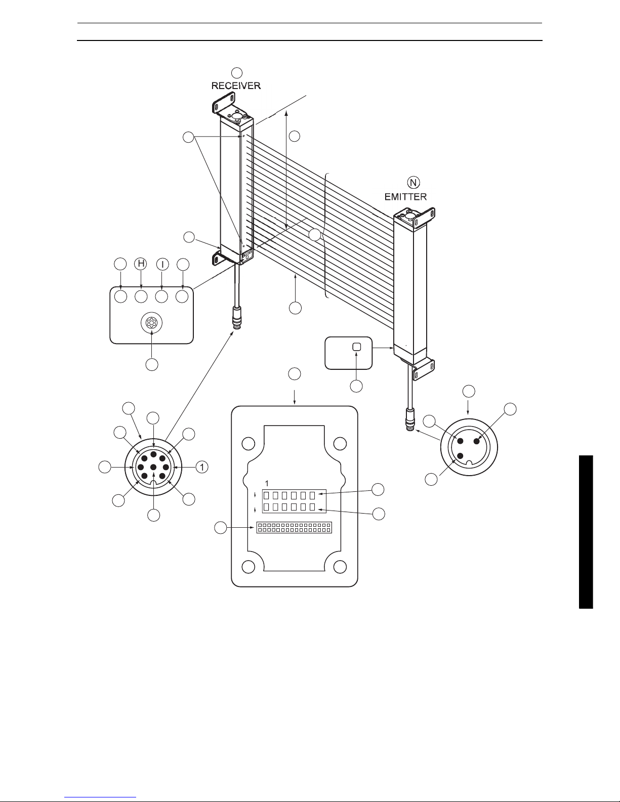
3 System Components and Indicators
Refer to “Figure 3-1” on page 5 for the location of the components and indicators listed below.
Table 3-1 System Components Identification
Note: OSSD outputs must have a minimum load or the F3SL system will enter an alarm condition. For the pur-
pose of testing prior to final installation, this load can be supplied by a 10K ohm resistor (included in documentation kit). See Figure 7-1 for details.
Chart
#
Chart
#
C RECEIVER N EMITTER
D
Upper Most/Lower Most Beam Indicators - Red
O
Status Indicator - Yellow
E
Removable End Cap. Access to configuration
switches
P
Emitter connections
F Program button (must remove security screw) 10 Drain - Shield(Uninsulated) Wire
G
Channel Select or Floating Blanking Indicator Yellow
11 +24VDC - White Wire
H
Interlock or Fault Indicator - Yellow
12 0VDC(GND) - Brown Wire
I
Machine Stop Indicator - Red
Q
Synchronization Beam
J
Machine Run Indicator - Green
R
Optical axis
K Receiver connections S Protective height (detection zone)
1 OSSD1 - Orange Wire (see note below)
2 0VDC(GND) - Brown Wire
3 Drain - Shield(Uninsulated) Wire
4 +24VDC - White Wire
5 Auxiliary Out - Violet Wire
6 MPCE - Pink Wire
7 Start - Gray Wire
8 OSSD2 - Yellow Wire (see note below)
L Inside Receiver End Cap
B Switch B
A Switch A
M Connector
☛
Page 11
3 System Components and Indicators
5
Figure 3-1 System Drawing
O
C
INDICATOR SIDE
1
3456
Page 12

4-1 Operating States
4 System Operation
6
4 System Operation
A F3SL system is a microprocessor-controlled, infrared transmitted-beam safety light curtain. The system consists of a receiver assembly and a emitter assembly. The receiver and emitter assemblies are not physically interconnected.
F3SL system is often used where personnel protection is required. Typical applications include robotic work
cells, filter presses, injection molders, food processing equipment and automated assembly equipment.
4-1 Operating States
The operating condition of a F3SL system is described in terms of states. The following operating states exist
for the F3SL system.
4-1-1 Machine Run
The two receiver safety outputs are in the ON state, the green machine run indicator is lit, and the auxiliary output
is in a state consistent with its configuration. See Section 7-2 on page 13. The protected machine is allowed to
operate. Pressing and releasing the start button has no effect.
4-1-2 Machine Stop
The two receiver safety outputs are in the OFF state, the red machine stop indicator is lit, and the auxiliary output
is in the follow state consisitent with the safety outputs. See Section 7-2 on page 13. The protected machine is
not allowed to operate.
4-1-3 Interlock
The two receiver safety outputs are in the OFF state, the red machine stop indicator and yellow interlock indicator are lit. The auxiliary output is in the follow state consisitent with the safety outputs. See Section 7-2 on page
13. The interlock state does not allow the protected machine to operate until the detection zone is clear of obstructions and the start button is pressed and released.
4-1-4 Alarm
The two receiver safety outputs are in the OFF state, the red machine stop indicator is lit, the yellow interlock
indicator is flashing, and the auxiliary output is in the OFF state. The alarm state does not allow the protected
machine to operate. The primary difference between alarm and interlock is that the F3SL system will remain in
the alarm state until the alarm is corrected, regardless of power cycling or an external start button press and
release.
4-2 Operating Modes
System operating modes determine the start-up and operating behavior of a F3SL system. Operating mode definitions rely on the operating states presented above. Operating mode selection is performed via configuration
switches in the removable cap on the bottom of the receiver.
Note: If internal alarms are detected by the F3SL system during power-up or operation, it will enter the alarm
state with its safety outputs in the OFF state.
4-2-1 Automatic Start
A F3SL system will power-up with its safety and auxiliary outputs OFF, and, if the detection zone is not obstructed, enter the machine run state. In this state, when an object is sensed entering the detection zone, the F3SL
system will change from machine run to machine stop and remain in this state until the obstruction is removed.
Once the detection zone is clear, the F3SL system will automatically change from machine stop to machine run.
4-2-2 Start Interlock
The F3SL system will power-up with its safety outputs OFF, and, if no alarms are detected, enter the interlock
state. To enter the machine run state, the detection zone must be clear (or an Exact Channel Select pattern satisfied), and then the operator must press and release the Start button. In the machine run state, when an object
is sensed entering the detection zone the F3SL system will change from machine run to machine stop. Once the
detection zone is clear, the F3SL system will automatically change from machine stop to machine run.
4-2-3 Start/Restart Interlock
A F3SL system will power-up with its safety outputs OFF, and, if no alarms are detected, enter the interlock state.
To enter the machine run state, the detection zone must be clear (or an Exact Channel Select pattern satisfied),
☛
Page 13

4 System Operation
4-3 Operating Mode Selection
7
and then the operator must press and release the Start button. In the machine run state, when an object is
sensed entering the detection zone the F3SL system will change from machine run to interlock. The F3SL system will remain in the interlock state even after the obstruction is removed from the detection zone. To enter the
machine run state, the operator must press and release the start button. If any obstruction is present in the detection zone when the start button is pressed and released, the F3SL system will remain in the interlock state.
Note: The definitions above mention a start button. See Section 10–“Connecting To The Machine Control Cir-
cuit” for wiring of the start button.
4-3 Operating Mode Selection
Operating mode is selected by setting positions 1 and 2 of Switches A and B, located inside the receiver end
cap. Refer to Table 4-1. Any mismatch between the settings of Switch A and B will result in an alarm condition.
To access Switches A and B, remove the four captive screws which secure the largest receiver end cap. Set
these switches before mounting the recieiver.
WARNING
Perimeter guarding installations must not allow a machine or robot to restart automatically. Use a start switch
placed outside and within view of the hazardous area.
WARNING
Disconnect power before removing end caps.
Table 4-1 Operating Mode Switch Settings
SWITCH A SWITCH B
OPERATING MODE1212
Automatic Start (default setting) ON ON ON ON
Start interlock OFF ON OFF ON
Start/Restart interlock OFF OFF OFF OFF
Not Allowed ON OFF ON OFF
Page 14

5-1 Exact Channel Select (ECS)
5 Detection Options
8
5 Detection Options
5-1 Exact Channel Select (ECS)
ECS disables selected, fixed areas of the detection zone by masking off specific, fixed beam locations. ECS is
helpful when stationary objects such as tooling and fixtures permanently obstruct a portion of the detection zone.
ECS requires that any portion of the detection zone which is blocked remain blocked. If the obstruction is removed the F3SL system will enter a machine stop state. The synchronization beam (the beam nearest to the
cable) cannot be selected. Also, one additional beam must remain unblocked. A channel is defined as one emitter/receiver pair or “beam”.
See "Table 5-1 System Response to Exact Channel Select" on page 8 for a diagram of F3SL system response
during operation with ECS active.
5-2 Floating Blanking
Up to two channels can be disabled at any location in the detection zone (except for the synchronization beam)
without the F3SL system going to the machine stop state. The disabled channels are not fixed at a single location
but “float” through the detection zone.
See Table 5-2 for a diagram of F3SL system response during operation with Floating Blanking active.
WARNING
Use of Exact Channel Select and/or Floating Blanking will make the F3SL system less sensitive to objects in
the detection zone. Improper use of either can result in severe injury to personnel. Exact Channel Select
may require a hard barrier guard (see “9-2-1 Additional Guarding” on page 19), Exact Channel Select or
Floating Blanking may require an increase in the safety distance. Read the following section carefully.
Table 5-1 System Response to Exact Channel Select
Channel Select
Status
Exact Channel Select
Inactive
Exact Channel Select
Inactive
Exact Channel Select
Active
Exact Channel Select
Active
Exact Channel Select
Active
Channel 1
Channel 2
Channel 3
Channel 4
Channel 5...
System
Response
machine run machine stop machine run machine stop machine stop
Page 15

5 Detection Options
5-3 Using Exact Channel Select with Floating Blanking
9
5-3 Using Exact Channel Select with Floating Blanking
When both Exact Channel Select and Floating Blanking are selected, the floating channels are allowed to occur
anywhere within the detection zone (except for the beam nearest the cable), even within the area selected by
Exact Channel Select. In these areas, a channel that should normally be blocked is allowed to be clear.
Table 5-2 System Response to Floating Blanking
Floating
Blanking
Inactive
1
Channel
Floating
Blanking
Active
1
Channel
Floating
Blanking
Active
1
Channel
Floating
Blanking
Active
1
Channel
Floating
Blanking
Active
2
Channel
Floating
Blanking
Active
2
Channel
Floating
Blanking
Active
2
Channel
Floating
Blanking
Active
2
Channel
Floating
Blanking
Active
2
Channel
Floating
Blanking
Active
2
Channel
Floating
Blanking
Active
2
Channel
Floating
Blanking
Active
Channel 1
Channel 2
Channel 3
Channel 4
Channel 5...
System Response
1
Exception
machine stop
0
Exceptions
machine
run
1
Exception
machine
run
2
Exceptions
machine stop
2
Exceptions
machine stop
0
Exceptions
machine
run
1
Exception
machine
run
2
Exceptions
machine
run
2
Exceptions
machine
run
3
Exceptions
machine stop
3
Exceptions
machine stop
3
Exceptions
machine stop
Table 5-3 Icon Key for Tables 5-1 and 5-2
Symbol Description
= Optical channel is not blocked.
= Optical channel is blocked.
= Optical channel is selected by Exact Channel Select.
= Optical channel is selected by Exact Channel Select and is blocked.
WARNING
Using Exact Channel Select with Floating Blanking is an advanced feature. All situations which may occur to
the F3SL system detection zone must be carefully considered. The F3SL system may be less sensitive to
objects in the detection zone. The safety distance must be increased. Failure to do so may cause serious
injury.
To prevent a hand or other objects to enter the channel-selected part, provide a physical guard such as a
fence.
Page 16

5-4 Activating and Programming Exact Channel Select
5 Detection Options
10
5-3-1 The Effect of Exact Channel Select and Floating Blanking on Minimum Object
Resolution
When Exact Channel Select and/or Floating Blanking is active, the safety distance is affected. Exact Channel
Select and Floating Blanking desensitize the light curtain and increase the size of the minimum object detected.
The increase is equal to the channel spacing distance for each channel that is disabled.
• A F3SL system with one channel disabled has a minimum object sensitivity of:
30mm + 22mm =52mm (2.05 inches).
• A F3SL system with two channel disabled has a minimum object sensitivity of:
30mm + 22mm + 22mm =74mm (2.91 inches).
If the size of the object detected by the F3SL system increases, the minimum safe distance must increase. Use
the minimum object sensitivity given in to determine the new figure to use when computing the safety distance.
5-4 Activating and Programming Exact Channel Select
Exact Channel Select is activated by setting position 4 of Switches A and B, located inside the receivere end
cap. Refer Figure 3-1 and Table 5-5. Any mismatch between the settings of Switches A and B will result in a
alarm condition. To access Switches A and B, remove the four captive screws which secure the largest receiver
end cap. Set these switches before mounting the receiver.
To program an ECS pattern, the F3SL system must be in the machine stop state. An ECS pattern is stored by
blocking the appropriate area of the detection zone and pressing, then releasing the program button (See Figure
3-1 for location).
The F3SL system will then enter the interlock or machine stop condition, regardless of the operating mode. The
Start button may be pressed-and-released or power may be cycled to enter the machine run state. Subsequent
power cycles will result in operation in accordance with the configured operating mode.
A new ECS pattern is recorded when the system is in the machine stop state with no alarms, the configuration
switches are correctly set, and the Program button is pressed and released. If the configuration switches are
subsequently set to disable ECS, the stored ECS pattern is cleared.
Note: The Program button is accessed by removing a tamper-resistant screw. A wrench which matches this
screw is provided in the receiver hardware package. This wrench should be kept under supervisor control. The tamper-resistant screw must be replaced to maintain the environmental integrity of the F3SL
system.
Table 5-4 Sample and D
pf
Factors
Total Number of Beams
Disabled by Exact Channel
Select and/or Floating Blanking
Minimum Object Resolution d Depth Penetration Factor, Dpf
for use with ANSI Formula (Dpf
= 3.4 (d-7.0) mm)
None 30 mm (1.18 inches) 78.2mm (3.08 inches)
1 Beam 52 mm (2.05 inches) 153.0 mm (6.02 inches)
2 Beams 74 mm (2.91 inches) 227.8 mm (8.97 inches)
3 Beams 96 mm (3.78 inches) 302.6 mm (11.91 inches)
4 Beams 118 mm (4.65 inches) 377.4 mm (14.86 inches)
5 Beams 140 mm (5.51 inches) 452.2 mm (17.80 inches)
etc...
WARNING
Disconnect power before removing end cap.
Page 17

5 Detection Options
5-5 Activating Floating Blanking
11
5-5 Activating Floating Blanking
Floating Blanking (either one- or two- beam) is activated by setting positions 5 and 6 of Switches A and B located
inside the receiver end cap. Refer to Figure 3-1 and Table 5-5. Any mismatch between the settings of Switch A
and B will result in an alarm condition. To access Switches A and B, remove the four captive screws which secure the largest receiver end cap. Set these switches before mounting the receiver. Use of the program button
is not required.
Note: When ECS or Floating Blanking is active, the amber ECS/FB Indicator will illuminate to indicate that the
F3SL system is operating in a less sensitive state.
Table 5-5 Detection Option Switch Settings
SWITCH A SWITCH B
OPERATING MODE 456456
Exact Channel Select Active ON
ON
Exact Channel Select Inactive
(default setting)
OFF
OFF
One-channel Floating Blanking Active ON OFF ON OFF
Two-channel Floating Blanking Active OFF ON OFF ON
Floating Blanking Inactive (default setting) OFF OFF OFF OFF
Not Allowed – alarm Condition ON ON ON ON
Page 18

6-1 Upper Most/ Lower Most Beam Indicators
6 DIAGNOSTIC AND TEST FEATURES
12
6 DIAGNOSTIC AND TEST FEATURES
6-1 Upper Most/ Lower Most Beam Indicators
The F3SL system has a visible, red Upper Most/Lower Most Beam Indicators (BI), adjacent to one for upper most
and another one for lower most infrared beam. These BI are located on the receiver. The BI will light when the
infrared beam fails to meet the conditions necessary for the F3SL system to remain in the machine run state.
When the synchronization beam is broken, all BI will light.
BI are not a safety critical component. An BI failure will not cause a alarm condition and the F3SL system will
continue to operate.
6-2 Synchronization Beam
Synchronization between the F3SL system emitter and receiver is optical. The beam closest to the cable connector supplies this signal. When this beam is blocked, the system will enter a machine stop state and both
Beam Indicators (BI) will light. When the beam is cleared, the system will resynchronize itself and enter a state
consistent with its operating mode.
6-3 Machine Primary Control Element (MPCE) Monitoring
MPCE monitoring is an important safety function. It monitors the F3SL system interface to the guarded machine
and checks to ensure that the control elements are responding correctly to the light curtain and to detect any
inconsistency between the two machine MPCE. This is necessary to detect a malfunction within the interface
which presents a stop signal from reaching the machine controller.
Connections for MPCE monitoring are made at the receiver. On power-up, the F3SL system looks for an MPCE
closed condition. If this is found, it will enter a state consistent with the selected operating mode. When the F3SL
system enables its safety outputs, it monitors the MPCE for a closed-to-open transition. This transition must occur within 300 ms or the F3SL system considers the MPCE alarmed. The F3SL system will then enter an alarm
state. Additionally, if the MPCE connectors are incorrectly wired, the F3SL system will enter an alarm state.
Note: For proper operation of the F3SL system when MPCE is not active, the MPCE input must be wired to the
F3SL system ground.
6-3-1 Activating and Deactivating MPCE Monitoring
MPCE monitoring is activated by setting position 3 of Switches A and B located inside the receiver end cap. Refer to Figure 3-1 and Table 6-1. Any mismatch between the settings of Switches A and B will result in an alarm
condition. To access Switches A and B, remove the four captive screws which secure the largest receiver end
cap. Set these switches before mounting the receiver.
WARNING
Disconnect power before removing end caps.
Table 6-1 MPCE Switch Settings
Switch A Switch B
MPCE MONITORING
ACTIVE OR NOT ACTIVE
33
Active OFF OFF
Not Active (default setting) ON ON
Page 19

7 Outputs
7-1 Safety Outputs
13
7 Outputs
7-1 Safety Outputs
The F3SL system receiver supplies two independent PNP-type, safety outputs to provide run/stop signals to the
guarded machine. In the machine run state, the safety outputs are electrically conducting and source 500 milliamps of current at 24 VDC. In the machine stop state, the outputs are not electrically conducting.
Note: The safety outputs must have a minimum load or the F3SL system will enter a alarm condition. For the
purpose of testing prior to final installation, this load can be supplied by a 10K ohm resistor (included in
documentation kit). See Figure 7-1 for details
.
Figure 7-1 Connection of load to safety outputs for testing.
7-2 Auxiliary Output
This is not a safety output. F3SL systems suplies one PNP-type auxiliary output.In the on state, this Auxiliary
output will source up to 100mA, and will be on when the safety outputs are on. (Follow mode)
WARNING
This product is designed for use on a 24 VDC, negative ground (protective earth) electrical system only.
Never connect the F3SL to a positive ground (protective earth) system. With a positive ground (protective
earth) wiring scheme, certain simultaneous shorts of both safety outputs may not be detected and the
guarded machine may not stop resulting is severe operator injury.
24 VDC
SUPPLY
OSSD1 OSSD2 0 V
24 V+
10K ohm 10K ohm
Page 20

8-1 European Safety Distance Formulas
8 Safe Mounting Distance
14
8 Safe Mounting Distance
A F3SL system must be mounted far enough from the machine danger zone so the machine will stop before a
hand or other body part reaches the hazardous area. This distance is called the safety distance. It is a calculated
number based on a formula. See Figure 8-1 for an illustration of the safety distance.
Figure 8-1 Safe Mounting Distance
Regardless of the calculated distance, a F3SL system should never be mounted closer than 5.5 inches
(140 mm) from the point of operation hazard. This is required by Table 0-10 in OSHA 1910.217.
8-1 European Safety Distance Formulas
The following discussion is based on standard EN999:1998 and applies to light curtains used in industrial
environments.
8-1-1 Safety Distance Formula for Systems with a Minimum Object Resolution
of 40 mm or Less
When the minimum object resolution of the system is 40 mm or less, use the following formula:
S = (K x T) + C
where:
S = the minimum distance in millimeters, from the danger zone to the detection point, line, plane or zone.
K = 2000 mm/s
T = the overall system stopping performance in seconds.
T = t
m
+ t
s
tm = maximum stopping time of the machine is seconds.
t
s
= response time of the safety light curtain in seconds.
This response time is given in 2-2 Technical Specifications.
C = 8(d-14 mm), but not less than zero.
d = the minimum object detection of the F3SL system in millimeters.
i.e.:
S = (2000 mm/s x T) + 8(d – 14 mm)
WARNING
Never install a F3SL system without regard to the safety distance. If the F3SL system is mounted too close
to the point of operation hazard, the machine may not stop in time to prevent an operator injury.
Light Curtain
D
s
Ds is the minimum safe distance
between the light curtain sensing
field and the point of operation
hazard (pinch point).
Page 21

8 Safe Mounting Distance
8-2 US Safe Distance Formulas
15
<Calculation example>
Under the conditions of T
m
= 0.05s, Ts=0.02s and d=30 mm,
S = 2000 mm/s x (0.05
s
+0.02s) + 8 (30 mm-14 mm)
= 268 mm
This formula applies for all minimum distances of S up to and including 500 mm. The minimum value of S shall
not be less than 100 mm.
If S is found to be greater than 500 mm using the formula above, then the formula below can be used. In this
case the minimum value of S shall not be less than 500 mm.
S = (1600 mm/s x T) + 8(d – 14 mm)
8-1-2 Safety Distance Formula for Systems with a Minimum Object Resolution Great-
er Than 40 mm
When the minimum object resolution of the system is greater than 40 mm, use the following formula:
S = (K x T) + C
where:
S = the minimum distance in millimeters, from the danger zone to the detection point, line, plane or zone.
K = 2000 mm/s
T = the overall system stopping performance in seconds.
T = t
m
+ t
s
tm = maximum stopping time of the machine is seconds.
t
s
= response time of the safety light curtain in seconds.
This response time is given in Section 2-2—Technical Specifications.
C = 850 mm.
i.e.:
S = (1600mm x T) + 850mm
8-1-3 Factors Affecting the Safety Distance Formula
When light curtains are used for machine initiation, their minimum object resolution must be 30 mm or smaller
(based on EN 999, other standards may vary). In this case the formula given in Section 8-1-1 applices except
that the minimum distance S shall be greater than 150 mm./
For parallel approach the formula for C becomes:
C = 1200 mm – (0.4 x H), but not less than 850 mm
H = the height of the detection zone above the floor in mm.
8-2 US Safe Distance Formulas
In the United States two formulas exist to properly determine the safety distance. OMRON recommends the formula provided by the American National Standards Institute (ANSI) which incorporates additional factors when
compared to the formula required by OSHA.
The ANSI formula given below is for a normal approach to the light curtain.
D
s
= K x (Ts + Tc + Tr + Tbm) + D
pf
Where:
Ds = minimum safety distance, in inches, between the F3SL detection zone and the nearest point of operation
hazard.
K = hand speed constant in inches per second. The ANSI standard value is 63 inches/second which assumes
the operator starts a hand motion toward the point of operation from rest. According to ANSI B11.19-1990, “The
value of the hand speed constant, K, has been determined by various studies and although these studies indicate speeds of 63 in./sec. to over 100 in./sec., they are not considered conclusive determinations. The user
should consider all factors, including the physical ability of the operator, when determining the value of K to be
used.”
Page 22

8-2 US Safe Distance Formulas
8 Safe Mounting Distance
16
T
s
= the stop time of the press (or machine) in seconds, measured from the final de-energized control element.
Measured at maximum closing velocity.
T
c
= the response time, in seconds, of the press or machine control circuit to activate the machine’s brake.
Note: T
s
+ Tc is usually measured together by a stop time measuring device.
T
r
= the response time of the F3SL system, in seconds.
This response time is given in 2-2 Technical Specifications on page 2.
T
bm
= the additional stopping time, in seconds, allowed by the brake performance monitor before it detects stop
time deterioration.
The T
bm
factor allows consideration for brake wear, adding extra stop time allowed by the brake monitor. There-
fore, T
bm
= Brake monitor set point - (Ts + Tc).
Note: If the guarded machine is not equipped with a stop time performance monitor, a percentage increase fac-
tor should be applied to the stop time of the machine to allow for braking system wear. Contact your machine manufacturer for information.
D
pf
= This is related to the minimum object sensitivity of the F3SL system. By knowing the minimum object sen-
sitivity, S, of the F3SL system, D
pf
is read directly from Table 5-4 depending on the F3SL model being installed.
Page 23

9 Installation
9-1 Reflective Surface Interference
17
9 Installation
9-1 Reflective Surface Interference
A reflective surface adjacent to the detection zone can deflect the optical beam and may cause an obstruction
in the zone not to be detected. (See Figure 9-2 and Figure 9-3.) The reflective surface may be part of the machine, mechanical guard or workpiece. Therefore, a minimum distance (d) must exist between the reflective object and the center line of the F3SL detection zone. The Test Procedure (Appendix B) must be used to test for
this condition.
Figure 9-1 Correct Mounting Example with Proper Alignment
.The interruption is clearly detected. The reflective object is outside of the beam angle.
Figure 9-2 Unsafe Mounting Example
The interruption is not detected because of the reflection. The reflective object is inside the beam angle.
WARNING
Install the F3SL system so as not to be affected by the reflection from the reflective surface. Failure to do so
may cause the system undetectable, resulting in severe operator injury.
Emitter
Receive
r
Approach direction
Central beam
Light beam interrupted
d
Reflective Surface
Perimeter of danger area
Interruption
a
Beam Angle, a
Operating Range, R
Emitter
Receiver
Approach direction
Central beam
Light beam interrupted
d
Reflective Surface
Perimeter of danger area
Reflection
Interruption
a
Beam Angle, a
Page 24

9-1 Reflective Surface Interference
9 Installation
18
Figure 9-3 Unsafe Mounting Example
Interruption is not detected because of the reflection. Reflective surface interference may also appear above and
below the sensing field.
Figure 9-4 Worst Case Alignment Example
This example shows the minimum distance from the reflective surface, d, to one side of the beam center line.
Figure 9-5 Minimum Distance from a Reflective Surface as a Function of Range
Receiver
Reflective Surface
Perimter of danger area
Reflection
Interruption
a
Sensing Field
Emitter
Emitter
Receiver
Beam Angle, a
d
Reflective Surface
Operating Range, R
a
a
Perimeter of danger area
0
100
300
500
700
900
2m
4m
6m
8m
10m
12m
14m
16m
Minimum distance
Range (m)
18m
20m
1.1m
1.3m
0.3m
d(mm)
Page 25

9 Installation
9-2 General Considerations
19
9-2 General Considerations
9-2-1 Additional Guarding
Areas of access to the point of hazardous operation not guarded by the F3SL system must be protected by suitable means such as a fixed barrier guard, an interlocked guard or a safety mat. See Figure 9-6.
Figure 9-6 Correct Light Curtain Installation Example
9-2-2 Installation of Multiple Systems
When two or more F3SL systems are mounted in close proximity and in alignment with each other, precautions
should be taken to avoid one curtain interfering with another. This can be corrected by mounting the emitters
and receivers back-to-back or stacked. See Figure 9-7 for reference.
Hazard
Zone
D
s
LIGHT CURTAIN
Mechanical
Barrier
Supplemental
Guarding
Example
Page 26

9-2 General Considerations
9 Installation
20
Figure 9-7 Multiple Light Curtain Installation Configurations
9-2-3 Access to Configuration Switches
Switches to configure the F3SL system operating features are located inside the end cap of the receiver and
Exact Channel Select is programmed via a push button accessed from the front of this end cap. If it will be necessary to change the configuration or Exact Channel Select program during operation, access to this cap must
be maintained. When reinstalling end caps, tighten the four slotted end cap screws in a diagonal pattern to a
torque of 7 to 9 in-lbs. (0.8 to 1 Nm)
9-2-4 Detection Zone
The F3SL system detection zone is delineated by the inside edge of the emitter and receiver endcaps. The area
outside these marks is not protected. Position the F3SL system so that it is only possible to access the danger
point through the detection zone.
9-2-5 Alignment
Physical alignment of the emitter and receiver units is easiest when the F3SL system is in the automatic start
operating mode with Exact Channel Select inactive. The units should be in the same plane and at equal height.
The Upper Most/ Lower Most Beam Indicators will light when a beam is out of alignment. See Section 6-1—Upper Most/ Lower Most Beam Indicators for details.
WARNING
Isolate power before removing end cap.
Emitter
Receiver
Machine 2Machine 1
Emitter
Receiver
NOT RECOMMENDED INSTALLATION
This arrangement may be subject
to interference between the two
light curtains.
Emitter
Receiver
Machine 1
Emitter
Receiver
Machine 2
PREFERRED INSTALLATION
The receivers are mounted
back to back.
Machine 1
Receiver
Receiver
Emitter
Emitter
PREFERRED INSTALLATION
An alternating receiver to
transmitter orientation
is suggested.
Page 27

9 Installation
9-2 General Considerations
21
9-2-6 Cable Assemblies
Receiver cable connections are color coded red and emitter cable connections are black. Details of the pin-out
connections for the OMRON-supplied connector are provided in Table 3-1.
9-2-7 Input Power Requirements/Connections
The F3SL system operates directly from 24 VDC ±20%. Power to the F3SL system must come from a dedicated
power supply which meets the requirements of IEC 60204-1 and IEC 61496-1. The F3SL system internally generates voltages for its own use. No other devices should be connected to these voltages.
9-2-8 Special Requirements for Perimeter Guarding
In perimeter guarding applications the F3SL system detection zone is placed around the outside perimeter of a
guarded machine or robot. This placement leaves space for personnel to stand between the detection zone and
the hazardous machine.
In this case, the guarded machine must only be restarted using a switch located outside and with a full view of
the area of hazardous motion. Operation of the F3SL system in the start/restart interlock operating mode is suitable for perimeter guarding.
9-2-9 Marking Minimum Object Resolution
Serial number labels on the emitter and receiver indicate three possible minimum object resolutions. During installation, use a permanent marker to obscure the object resolutions not set. This will depend on whether no
floating blanking, 1-beam or 2-beam floating blanking is set. See Section 5-3-1 for information.
9-2-10 Presence Sensing Device Initiation
Using the light curtain to initiate a machine after an object is removed from the sensing area is called Presence
Sensing Device Initiation (PSDI). Use of PSDI places additional requirements on the guarding and safety controls. It can restrict advanced light curtain features such as Floating Blanking and Exact Channel Select. Good
sources of reference for PSDI include: ANSI RIA 15.06-1999, OSHA 1910.217(h), and ANSI B11.2-1995.
Page 28

10-1 Connecting Via Two Force-Guided Relays
10 Connecting To The Machine Control Circuit
22
10 Connecting To The Machine Control
Circuit
10-1 Connecting Via Two Force-Guided Relays
OMRON model G7SA relays provides force-guided relay outputs for machine control. See Figure 10-1 for the
preferred connection method using two force-guided relays.
Figure 10-1 Connection Method(Connecting Via Two Force-guided Relays)
WARNING
This product is designed for use on a 24 VDC, negative ground (protective earth) electrical system only.
Never connect the F3SL system to a positive ground (protective earth) system. With a positive ground (protective earth) wiring scheme, certain simultaneous shorts of both safety outputs may not be detected and the
guarded machine may not stop resulting is severe operator injury.
Never use only a single safety output to control the machine. Should this single output fail, the machine may
not stop, resulting in severe operator injury. The machine must be connected using both safety outputs.
0V
Ground
MPCE
2
S1
MPCE1MPCE2
Emitter
Receiver
Star t(gr ay)
+24V(white)
0V(brown)
Aux.Output(violet)
Shield
+24V(white)
0V(brown)
Control output 1(orange)
Control output 2(yellow )
M:Machine drive (e.g. three-phase motor)
S1:Start switch for interlock reset (NC contact)
MPCE1 and MPCE2: safety relay with 2 force-guided relays (recommended model: G7SA) and contactor
Shield
PLC
(PNP input)
,et c.
+24
VDC
Power
supply
Note 3
Note 1
Note 5
Note 5
Note 4
Note 1: In regards to MPCE1 and MPCE2, which perform final control of the machine, use safety relays equipped
with a force-guide function (e.g. OMRON model G7SA).
Note 2: If the MPCE monitor function is not used, short circuit the MPCE monitor line (pink) to 0V power supply.
Note 3: When the load is not connected to control outputs 1 and 2, this system will enter error state and not
operate properly. For testing during installation, connect the 10 KW resistor (included in documentation kit)
to the MPCE1 and MPCE2 position.
Note 4: When using this system in automatic start mode, short circuit the start line (gray) to 0V power supply.
Note 5: When wiring, be sure to connect the proper color cords. Note that colors of the power supply lines are
white for +24 VDC; brown for 0V,differing from those of ordinary sensors.
Note 6: Connect the attached surge-killer in parallel to MPCE1 and MPCE2.
Surge-killer
Surge-killer
Note 6
Page 29

10 Connecting To The Machine Control Circuit
10-2 Connection with OMRON safety relay unit Model G9SA
23
10-2 Connection with OMRON safety relay unit Model G9SA
When using in combination with Model G9SA-301, nullify the start/restart interlock and the external relay (MPCE) monitoring
features which are integrated in F3SL, before using the feature equivalent to Model G9SA-301
.
Figure 10-2 Connection Method(
Example of connection to Model G9SA-301 Safety Relay
Unit)
E1
0V
Ground
TH
SA
E2
Emitter
Receiver
Feedback loop
Model F3SL
Light ON
Blocked
Reset switch S1
Contacts K1 & K2 a
Contacts K1 & K2 b
Contacts KM1 & KM2 a
Contacts KM1 & KM2 b
PLC input
PLC output
KM3
S1:Reset switch
KM1 and KM2:Magnet contactor (model LP1D)
KM3:Solid-state contactor (model G3J)
M:3-phase motor
E1 and E2:24VDC power supply (model S82K)
Operation Chart
Star t(gr ay)
+24V(white)
0V(brown)
Aux.Output(violet)
Shield
+24V(white)
0V(brown)
Control output 1(orange)
Control output 2(yellow )
Shield
+24
VDC
MPCE
monitor(pink)
Page 30

11-1 Checkout Procedure
11 Checkout and Test Procedures
24
11 Checkout and Test Procedures
11-1 Checkout Procedure
Once the F3SL system has been configured, mounted, aligned and properly connected to the machine control
system, the initial Checkout Procedure detailed in Appendix A must be performed by qualified personnel. A copy
of the checkout results should be kept with the machine records.
11-2 Test Procedure
The Test Procedure must be performed by qualified personnel. To test the F3SL system with Exact Channel
Select and Floating Blanking disabled, use the OMRON-supplied test object. For applications where Exact
Channel Select or Floating Blanking are enabled, see Table 5-4 to determine the proper size test object.
11-3 Using the Test Object
When using the test object, guide it through the detection zone as shown below.
Figure 11-1 Test Object Pattern
12 Cleaning
Accumulation of oil, dirt and grease on the front filter of the F3SL emitter and receiver can effect the system operation. Clean filters with a mild detergent or glass cleaner. Use a clean, soft, lint-free cloth. Painted F3SL surfaces may be cleaned with a mild de-greasing cleaner or detergent.
WARNING
The tests outlined in the Test Procedure in Appendix B must be performed at installation, according to the
employer’s regular inspection program and after any maintenance, tooling change, set up, adjustment, or
modification to the F3SL system or the guarded machine. Where a guarded machine is used by multiple
operators or shifts, it is suggested that the test procedure be performed at each shift or operation change.
Testing ensures that the light curtain and the machine control system work properly to stop the machine.
Failure to test properly could result in serious injury to personnel.
ST
AR
T
ST
OP
Page 31

13 Dimensional Drawings and Patents
13-1 Dimensional Drawings
25
13 Dimensional Drawings and Patents
13-1 Dimensional Drawings
Figure 13-1 Dimensional Drawing
13-2 Patents
Elements of the electoronics and optics essential to meet the specifications and performance standards of
OMRON controls are covered by one or more of the following U.S.Patent Numbers:5015840; 5281809.
Table 13-1 Emitter and Receiver Lengths
Model A (mm) B (mm) C (mm)
F3SL-A0351P30 351 415 435.3
F3SL-A0523P30 523 587 607.3
F3SL-A0700P30 700 764 784.3
F3SL-A0871P30 871 935 955.3
F3SL-A1046P30 1046 1110 1130.3
F3SL-A1219P30 1219 1283 1303.3
F3SL-A1394P30 1394 1458 1478.3
F3SL-A1570P30 1570 1634 1654.3
F3SL-A1746P30 1746 1810 1830.3
F3SL-A1920P30 1920 1984 2004.3
F3SL-A2095P30 2095 2159 2179.3
ATI
ON
1.4
5
.
8
.
8
2.
00
L
G
1
6
1
6
MTG
)
1.
38
.
0
.
0
1.
97
.D
.
1
FRONT VIEW
IDE VIEW
.2
0
.
1
.4
5
11
LOTS (4
)
.
9
1.
35
4.
3
.2
8
.
0
.
3
.
37
1.
00
25.
4
.
1
2.
33
MTG
)
TO-CENTER
)
SLOT
ENTER
-
16.
6
.
66
10.
2
.4
0
1
7.
3
DETECTION ZONE
)
26.
7
1.
05
.
1
1.
50
4.0
5.
7
2.52
0.2
3
=
262.9/10.35 SHOWN
)
A = DETECTION ZON
E
4.
3
= A
+
.
32
mm (.3
)
INCHES (.01
)
Page 32

14-1 Receiver Endcap Indicator Lights
14 Troubleshooting
26
14 Troubleshooting
14-1 Receiver Endcap Indicator Lights
1. GREEN – The guarded machine is operating.
2. RED - The light curtain is blocked and the guarded machine is not operating.
3. YELLOW interlock- The light curtain is waiting for the start button to be pushed. The guarded machine is not
operating. If the LED is blinking, the light curtain is in a alarm condition.
4. AMBER FB or CS – The light curtain is operating in a reduced resolution mode.
14-1-1 Receiver Troubleshooting
If the yellow interlock LED is blinking:
1. Check the configuration for MPCE Monitoring. If MPCE Monitoring is inactive (via receiver endcap DIP
switches), the input (pink wire) must be connected to system ground. If MPCE is active, the input must be
connected to the normally closed contacts of the control relays of the guarded machine or the monitor terminal of the RM module. See Section 10—Connecting To The Machine Control Circuit for an example.
2. Make sure both DIP switches in the receiver endcap have been set properly and identically.
See Tables 4-1, 5-4 and 6-1 in manual.
3. Verify the power supply is within specified limits (+24V ± 20%).
4. Verify the light curtain is properly connected to the control relays of the guarded machine. If the light curtain
is not intended to be connected to control relays, see Section 7-1—Safety Outputs of manual for instruction.
5. Verify the control relays are within operating limits of the safety outputs. See Section 2-2—Technical Specifications.
6. Verify the cable lengths from the light curtain to the control relays are within specified limits.(Max.60 m is
possible.)
7. Call OMRON.
If the red LED is always on:
1. Verify the yellow LED on the emitter is on.
2. Realign the light curtain.
3. Verify the first beam (synchronization beam) is not obstructed.
14-2 Emitter Endcap Indicator Light
Yellow – The Emitter is active. If the LED is blinking, the light curtain is in a alarm condition.
14-2-1 Troubleshooting the Emitter
If the yellow LED is off:
1. Verify the cable is connected.
2. Verify the power supply is within limits (+24V ± 20%).
3. Call OMRON.
If the yellow LED is blinking:
1. Verify the power supply is within limits (+24V ± 20%).
2. Call OMRON.
Page 33

Appendix A —Checkout Procedure
A-1 Checkout Procedure Log
27
Appendix A —Checkout Procedure
A-1 Checkout Procedure Log
The following checkout procedure must be performed by qualified personnel during initial F3SL system installation and at least every three months or more frequently depending on machine usage and company guidelines.
Machine Identification:
Date:
Technician Signature:
Item Condition Comments
1. Verify that the guarded machine is compatible with the type of machine
which maybe used with the F3SL system. See Section 1—Important
Safety Warnings for further information.
Pass
Fail
2. Verify that the mounting distance of the F3SL system is equal to or
greater than the minimum safe distance from the danger point. See Section 8—Safe Mounting Distance for further information.
Pass
Fail
3. Determine that all access to the danger point not protected by the F3SL
system is guarded by other means, such as gates, fencing or other
approved methods. Verify that all additional guarding devices are installed
and operating properly.
Pass
Fail
4. Make sure the operator is not able to stand between the F3SL system
detection zone and the machine danger point. Verify that the light curtain
can only be reset from a position outside and within view of the hazardous
machine area.
Pass
Fail
5. Inspect the electrical connections between the guarded machine’s con-
trol system and the F3SL system. Verify that they are properly connected
to the machine such that a stop signal from the F3SL system results in an
immediate halt of the machine’s cycle. See Section 10—Connecting To
The Machine Control Circuit.
Pass
Fail
6. If the MPCE monitoring feature is not used, proceed to step 7. To test
the MPCE feature, verify that the feature has been enabled. Turn the
machine power on. Cycle the machine. Place a temporary jumper wire
between the MPCE connections. The F3SL should enter a alarm condition. Remove the temporary jumper. Press and release the start button.
Pass
Fail
7. Record the test results in the machine log, then perform the Test Proce-
dure.
Pass
Fail
Page 34

B-1 Test Procedure Log
Appendix B —Test Procedure
28
Appendix B —Test Procedure
B-1 Test Procedure Log
The following test procedure must be performed by qualified personnel during initial F3SL system installation,
according to the employer’s regular inspection program and after any maintenance, adjustment or modification
to the F3SL system or the guarded machine. Testing ensures that the light curtain, safety system, and machine
control system work together to properly stop the machine. Failure to test properly could result in serious injury
to personnel. To test the F3SL system, use the correct size test object.
Machine Identification:
Date:
Technician Signature:
Item Condition Comments
1. Disable the guarded machine. Apply power to the F3SL system. Pass
Fail
2. Visually inspect the machine to ensure that access to the danger point is
only through the F3SL detection zone. If not, additional guarding, including
mechanical barriers may be required. Verify that all additional guarding
devices and barriers are installed and operating properly.
Pass
Fail
3. Verify that the mounting distance of the F3SL system is equal to or
greater than the calculated minimum safety distance from the danger
point. See Section 8—Safe Mounting Distance for further information.
Ensure that the operator is not able to stand between the F3SL detection
zone and the danger point.
Pass
Fail
4. Check for signs of external damage to the F3SL system, the machine
and the electrical cables and wiring. If damage is found, lock the machine
off and report to the supervisor.
Pass
Fail
5. Interrupt the F3SL system detection zone with the proper size test
object. Move the test object inside the perimeter (along the top, sides and
bottom) of the detection zone and up and down through the center. At least
one Individual Beam Indicator must be lit while the test object is anywhere
in the detection zone. If in automatic start mode, verify that the red
machine start light is lit. If in start/restart interlock mode, verify that the red
machine stop and yellow interlock lights are on. Press and release start
button before proceeding to step 6.
Pass
Fail
6. Start the machine. While the machine is in motion, interrupt the detec-
tion zone with the test object. The machine should stop immediately. Never
insert the test object into the dangerous parts of the machine. With the
machine at rest, interrupt the detection zone with the test object. Verify that
the machine will not start with the test object in the detection zone.
Pass
Fail
7. Verify that the braking system is working properly. If the machine does
not stop fast enough, adjust the braking system or increase the distance
from the detection zone to the danger point.
Pass
Fail
8. If the safety devices or the machine fails any of these tests, do not run
the machine. Immediately tag or lockout the machine to prevent its use
and notify the supervisor.
Pass
Fail
 Loading...