

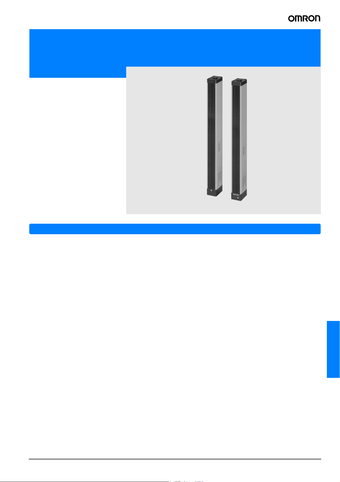
Safety light curtain for long distance detection
F3SL
20-m long-distance
detection. Safety
light curtain (Type 4)
is ideal for detection
of intrusion of human
bodies in large machines and conveyor
lines.
Features
● Complies with IEC standards, EN standards, and North
American standards. EC-based certification from TÜV for
EU machine directives. Can be used as a safety guard for
satisfaction of OSHA requirements for on-site labor safety
in North America.
● Special controller not needed. Detection of human body intrusion is possible using just the sensor unit.
● Includes "Start/restart interlock function" to prevent automatic reset of output.
● Includes floating blanking function (disables 1 or 2 non specific beams) and Fixed Blanking (disables specific beams)
● Built-in EDM (External Device Monitor). Feedback check is
possible without a controller
F3SL
G-59F3SL
Ordering Information
Sensors
Sensor type Shape Sensing distance Operating mode Detection width (mm) Model
351 F3SL-A0351P30
523 F3SL-A0523P30
700 F3SL-A0700P30
871 F3SL-A0871P30
1,046 F3SL-A1046P30
Through-beam Light ON
0.3 to 20m
1,219 F3SL-A1219P30
1,394 F3SL-A1394P30
1,570 F3SL-A1570P30
1,746 F3SL-A1746P30
1,920 F3SL-A1920P30
2,095 F3SL-A2095P30
Accessories (Order Separately)
Special cable (please order one each for the emitter and the
receiver)
Cable length Specifications
10 m
15 m F39-JL15A-L F39-JL15A-D
30 m F39-JL30A-L F39-JL30A-D
Connector
For emitter For receiver
F39-JL10A-L F39-JL10A-D
Model
Refection mirror (15% sensing distance attenuation)
Mirror
material
Glass
mirror
Note: Other sizes are available upon request.
Width
(mm)
Thickness
125 31
(mm)
Length
(mm)
460 F39-MDG460
607 F39-MDG0607
750 F39-MDG0750
907 F39-MDG0907
1,057 F39-MDG1057
1,357 F39-MDG1357
1,500 F39-MDG1500
1,657 F39-MDG1657
1,807 F39-MDG1807
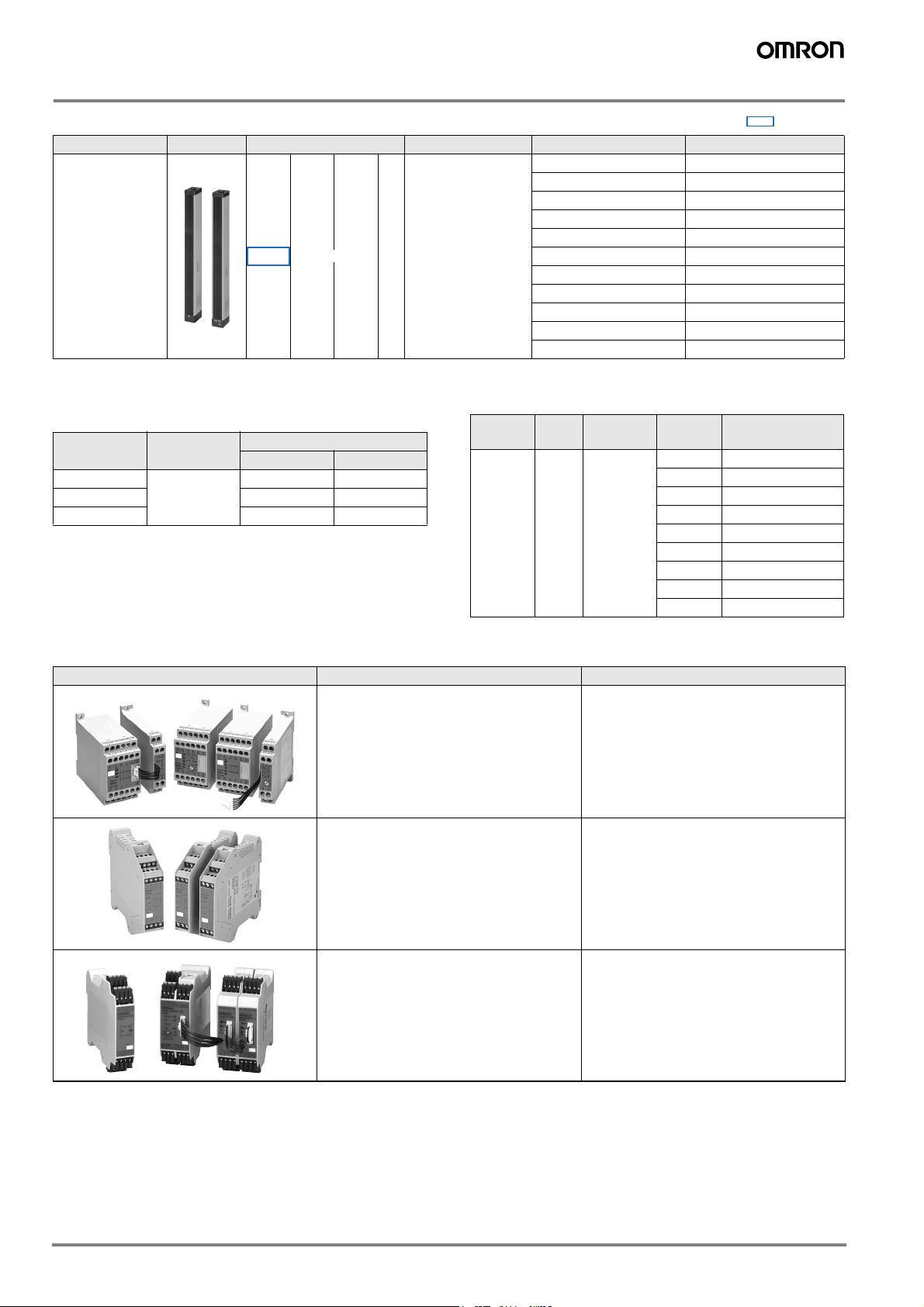
Safety Relay Unit
For controlling the outputs we recommend to use safety relay units G9SA or G9SB
Appearance Output Model
Infrared ray
Model
Expandable relay unit series with up to 8
safety relay outputs. Time delay for stop
category 1 can be realized.
(Please refer to page G-109)
Small size safety relay unit with 17.5 mm
and 22.5 mm size. Up to 3 safety relay
outputs are available.
(Please refer to page G-123)
Fletible and expandable safety unit with solid state outputs
G9SA series
G9SB series
G9SX series
G-60 Safety Sensors / Components

Rating/performance
Item
Model F3SL-
A0351
P30
F3SL-
A0523
P30
F3SL-
A0700
P30
F3SL-
A0871
P30
F3SL-
A1046
P30
F3SL-
A1219
P30
F3SL-
A1394
P30
Sensing distance 0.3 to 20 m
Optical axis pitch 22 mm
Number of optical
axes
Protective height
Min. sensing
object
Effective Aperture
angle
Light source
(wave length)
Power supply
voltage
Startup time after
turning on power
Current
consumption
Control output
Auxiliary output
16 24 32 40 48 56 64 72 80 88 96
351 mm 523 mm 700 mm 871 mm 1,046mm 1,219mm 1,394mm 1,570mm 1,746mm 1,920mm 2,095mm
Opaque object, 30-mm dia. or greater (52-mm or 74-mm dia. when using floating blanking)
Emitter/receiver: ±2.5° or less each (based on IEC61496-2 at detection distance of 3 m or greater)
Infrared LED (850 nm)
24 V DC ±20% including 5% ripple (p-p)
3 s max.
Emitter: 285 mA or less, receiver: 1.4 A or less (including load output current)
PNP transistor outputs x 2, load current 500 mA or less (residual voltage 2 V or less) (excluding voltage drop due to
cable extension), Light ON
Same signal as control output: PNP transistor outputs x 1 output (non-safety output), load current 100 mA or less
(residual voltage 1 V or less) (excluding voltage drop due to cable extension)
Protective circuits Output load short circuit protection, reverse power connection protection
Start/restart interlock function (select enable/disable with DIP switch)
Safety functions
• Blanking functions A Channel select (fixed blanking) B Floating blanking C No blanking (initial setting)
Select A, B, or C with DIP switch.
The optical axes for A fixed blanking are set by a teach button.
Diagnosis
functions
Response time
ON→OFF
Ambient
temperature
• Self diagnosis functions when the power is turned on
• External relay (MPCE) monitor function (connect external relay monitor input wire to contact b of external relay,
50 mA 24 V DC)
20 ms max. 25 ms max. 30 ms max. 35 ms max.
Operating/Storage: 0°C to 55°C (with no icing or condensation)
Ambient humidity Operating./Storage: 35% to 95% RH (no condensation)
Vibration
resistance
Shock resistance
Protective
Degree
Connection
method
Weight
(Packed state)
Materi-
al
Case Aluminum
Accessories
Applicable
standards
*1) ESPE (Electro-Sensitive Protective Equipment)
*2) AOPD (Active Opto-electronic Protective Devices)
Malfunction / durability: 10 to 50 Hz, amplitude 0.7 mm, 20 sweeps each in X, Y, and Z directions
Wrong operation / durability: 100 m/s2, 1,000 times each in X, Y, and Z directions
IEC Standard IP65
M12 Connector
11kg max.
Test rod, mounting brackets (upper/lower), operation manual, special hex wrench for program button access, test
load resistors (1 kΩ, 2 resistors), surge protector (2)
IEC (EN) 61496-1 TYPE4 ESPE
*1
IEC61496-2 TYPE4 AOPD
*2
F3SLA1570
P30
F3SL-
A1746
P30
F3SL-
A1920
P30
F3SL-
A2095P
30
F3SL
G-61F3SL

Connection
Wire the F3SL only after all power has been turned off.
Receiver Emitter
(see note 1)
M
Power
supply
M: Mechanical drive unit including 3-phase motor
S1: Start switch for interlock reset (NC contact)
MPCE2
MPCE1
(see note 2)
+24VDC
0V
Ground
MPCE monitor (pink)
Start (gray)
S1
(see note 4)
+24VDC (white)
(purple)
0V (brown)
Auxiliary output
PLC
(PNP input)
(see note 1)
(see note 3)
Control output 1 (orange)
etc.
MPCE1 MPCE2
Control output (yellow)
Surge killer
Shielded
(see
note 6)
Surge killer
0V (brown)
+24VDC (white)
Power supply
MPCE1, MPCE2: Contactor or safety relay with compulsory guide mechanism (G7SA is recommended)
Note: 1 .Please use a safety relay with forcibly guided contacts (such as the G7SA) for MPCE1 and MPCE2, which are relays that perform ultimate control of
the machine.
2 .If you do not intend to use the MPCE monitor function, short the MPCE monitor line (pink) to power supply 0 V.
3 .If a load is not connected to control output 1 and control output 2, an error will result and normal operation will not take place. For testing purposes
during installation or at other times, connect the 10 kΩ resistors included with the operation manual to the MPCE1 and MPCE2 positions.
4 .If you intend to use auto start mode, short the start line (gray) to power supply 0 V.
5 .Take care when wiring not to make any mistakes regarding the cable colors. In particular, the wire colors of the power supply line (+ 24 V DC: white,
0 V: brown) are different from the regular sensor wires.
6 .Connect the provided surge protector in parallel with MPCE1 and MPCE2.
Wiring method
Receiver unit connector Emitter unit connector
Front view diagram
(4)
(2)
(5)
(1)
(3)
(8)
(6)
(7)
Pin
No.
Signal name
Receiver
Wire color of
special cable
1 Control output 1 (OSSD1) Orange
20V Brown
3 Shielded ---
4 +DC24V White
Auxiliary output (AUXIL-
5
Purple
6 MPCE monitor Pink
7Start Gray
8 Control output 2 (OSSD2) Yellow
Front view diagram
(12)
(11)
(10)
Pin
No.
10 Shielded ---
11 +DC24V White
12 0V Brown
Special cable (purchased separately)
For emitter (3-pin) For receiver (8-pin) Cable length
F39-JL10A-L
F39-JL15A-L F39-JL15A-D 15 m
F39-JL30A-L F39-JL30A-D 30 m
Note: Please order one each for the emitter and the receiver.
Black
connector
Signal name
Emitter
F39-JL10A-D
Red
connector
Wire color of
special cable
10 m
ALL DIMENSIONS SHOWN ARE IN MILLIMETERS.
To convert millimeters into inches, multiply by 0.03937. To convert grams into ounces, multiply by 0.03527.
Cat. No. E15E-EN-01
In the interest of product improvement, specifications are subject to change without notice.
G-62 Safety Sensors / Components
 Loading...