

Page 1
形F3SJ-E□□□□N25
F3SJ-B□□□□N25
セーフティライトカーテン
取扱説明書
オムロン製品 をお買い上げ いただきありがとうござ い ま す 。この製 品を安
全に正しく使用していただくため、お使いになる前にこの説明書をお読み
になり、十分にご理解ください 。また 、ユーザーズマニュアルおよび製品付
属のクイックインストー ル マニュ ア ル も お 読 みに なり、十分にご理解くださ
い。この説明書とクイックインストール マニュア ルは 、お読みになった後も、
いつもお手元に置いてご利用ください 。
OMRON Corporation
©
公式EU加盟国言語による取扱説明書および署名済みEC適合宣言書の英語版は
www.industrial.omron.eu/safetyをご覧ください 。
*3126334-9B*
2011-2018
All Rights Reserved.
①
EC適合宣言
EC適合宣言
オムロンは、F3SJ-E/Bが以下のEC指令の要求に適合していることを 宣 言しま す 。
機械指令2006/42/EC
EMC指令2014/30/EU
法規・規格について
1. F3SJ-E/Bは、労働安全衛生法第四十四条の二による「型式検定」を受
けていません。したがって 、F3SJE/Bを日本国内で同法第四十二条で定め
れた「プレス機 械またはシャーの安全装置」として 使 用 することは できません。
2.
F3SJ-E/Bは、EU(欧州連合)機械指令附属書V第2項で指定される電気感
知式保護装置(ESPE:Electro-SensitiveProtectiveEquipment)です。
3.F3SJ-E/Bは、以下の規格に適合しています。
(1)欧州規格
EN61496-1(タイプ4 ESPE)、CLC/TS61496-2(タイプ4 AOPD)、
EN61508-1〜-3(SIL3)、EN61000-6-4、
ENISO13849-1:2008(カテゴリ4、PLe)
(2)国際規格
IEC61496-1(タイプ4ESPE)、IEC61496-2(タイプ4AOPD)、
IEC61508-1〜-3(SIL3)、ISO13849-1:2006(カテゴリ4、PLe)
(3)JIS規格
JISB9704-1(タイプ4ESPE)、JISB9704-2(タイプ4AOPD)
(4)北米規格
UL61496-1(タイプ4ESPE)、UL61496-2(タイプ4AOPD)、
UL508、UL1998、CAN/CSAC22.2No.14、
CAN/CSAC22.2No.0.8
F3SJ-E/Bは、EU公認機関TÜVSÜDProductServiceGmbHから、機械指
4.
令に基づくEC型式認証(タイプ4ESPE/タイプ4AOPD)を取得しています。
5.F3SJ-E/Bは、第三者評価機関ULより米国およびカナダ安全規格に対す
るリスティング 認 証(タイプ4ESPE/タイプ4AOPD)を取 得しています。
・タイプ4ESPE(UL61496-1)、タイプ4AOPD(UL61496-2)
6. F3SJ-E/Bは以下の規格を考慮した設計になっております 。なお、最終シス
テムを下記の規格、規制に適合させるためには、関連するすべての規格、
法規、規制にしたがって設計、使用してください 。不 明な点は、ULなどの専
門機関にご相談ください 。
・欧州規格EN415-4、EN692、EN693
・米国労働安全衛生規則OSHA29CFR1910.212
・米国労働安全衛生規則OSHA29CFR1910.217
・米国規格ANSIB11.1〜B11.19
・米国規格ANSI/RIA15.06
・カナダ規格協会 CSAZ142、Z432、Z434
・SEMIスタンダードSEMIS2
・厚生労働省「機械の包括的な安全基準に関する指針」
平成19年7月31日基発第0731001号
ご承諾事項
当社商品は、一般工業製品向けの汎用品として設計製造されています。従い
まして 、次に掲げる用途での使用を意図しておらず、お客様が当社商 品をこれ
らの用途に使用される際には、当社は当社商品に対して一切保証をいたしま
せん。ただし、次に掲げる用途であっても当社の意図した特別な商品用途の
場合や特別の合意がある場合は除きます 。
(a)高い安全性が必要とされる用途(例:原子力制御設備、燃焼設備、航空・
宇宙設備、鉄道設備、昇降設備、娯楽設備、医用機器、安全装置、その他
生命・身体に危険が及びうる用 途 )
(b)高い信頼性が必要な用途(例:ガス・水道・電 気 等の供 給システム、24時間
連続運転システム、決済システムほか権利・財産を取り扱う用途など)
(c)厳しい条件または環境での用途(例:屋外に設置する設備、化学的汚染を
被る設備、電磁的妨害を被る設備、振動・衝撃を受ける設備など)
(d)カタログ等に記載のない条件や環境での用途
*(a)から(d)に記載されている他、本カタログ等記載の商品は自動車(二輪車
含む。以下同じ)向けではありません 。自動 車に搭載する用 途には利用しない
で下さい。自動車搭載用商品については当社営業担当者にご相談ください 。
*上記は適合用途の条件の一部です。当社のベスト、総合カタロ グ 、 デ ータシ ー
ト等最新版のカタログ 、マニュアルに記載の保証・免責事項の内容をよく読 ん
でご使 用ください。
ら
安全上のご注意
●安全に使用していただくための 表 示と意 味について
この取扱説明書では、F3SJ-E/Bを安全にご使用いただくために、注意事項を次
のような表 示と記 号で示しています 。ここで 示した 注 意 事 項は 安 全に 関す る重 大
な内容を記載していますので、必ず守ってください 。表 示と記 号は次のとおりです。
正しい 取り扱 いをしなけれ ば 、この危険のために、
警告
●
図記号の
意味
●警告表示
使用者について
F3SJ-E/Bの設置や設定、および機械制御システムへの組み込みは必ず適
切な訓練を受けた有資格 者が実 施してください 。資格のない作業者が実施
すると正しく動作しなくなり、人体が検 出されず、重傷を負う恐れがあります 。
使用者は本書をよく読 んで 、設置手順、動作確認手順、およびメンテナンス
手順を十分に理解した上で使用してください 。
取り付ける機 械につ いて
電気的制御による急停止が不可能な機械には適用できませ ん 。たとえば、
フル回転クラッチを 用 い た 機 械プレスには 使 用しない でください 。機械の
危険部に到達する前に機械が止まらず 、重傷を負う恐れがあります 。
軽傷・中程 度の傷害を負ったり、万 一の場合には
重症や死亡にいたる恐れがあります 。また 、同様に
重大な物的損害を受ける恐れがあります 。
一般 的な禁止を示します。
一般 的な指示を示します。
感電の可能性についての注意を示します。
警 告
警 告
取り付けにつ いて
警 告
F3SJ-E/Bを設置後、機械が動作しない状態でF3SJ-E/Bが意図したと
おりに 動 作 することを必ず確認してください 。意図したとおりに設定
されていない場合、人体が検 出されず、重傷を負う恐れがあります 。
F3SJ-E/Bと危険部の間には、必ず安全距離を確保してください 。機械
の危険部に到達する前に機械が止まらず 、重傷を負う恐れがあります 。
人体が検出エリアを通過してのみ機械の危険部に到達できるように機械周
辺に防護構造物を設置してください 。機械の危険部で作業を行うとき、常に
人体の一部が検出エリア内に残るようにし、死角が発生しないように 設 置し
てください。機械の危険部とF3SJ-E/Bの検出エリアの間 に人 体 が入り込
んでしまう場合は、インターロックがか かるシステムとし、機械の再始動を
防止してください 。人 体が検出されず、重傷を負う恐れがあります。
インターロックリセットスイッチ は 、危険エリア全 体が 見え、かつ危険エリア
内から操作できない位置に設置してください 。
F3SJ-E/Bは、危険エリアからの飛来物に対して人体を防護する
ことは できません 。別途覆いまたは囲いを設けてください 。
F3SJ-E/Bの設置は光沢面からの影響を受けないように 設 置 して
ください 。検出不能状態となり、重傷を負う恐れがあります 。
複数セットのF3SJ-E/Bを使用するときは 、しゃ光板を使用する
などして 、相互干渉が発生しないように設置してください 。
本体の取りつけ、コードコネクタは確 実に締めてください 。
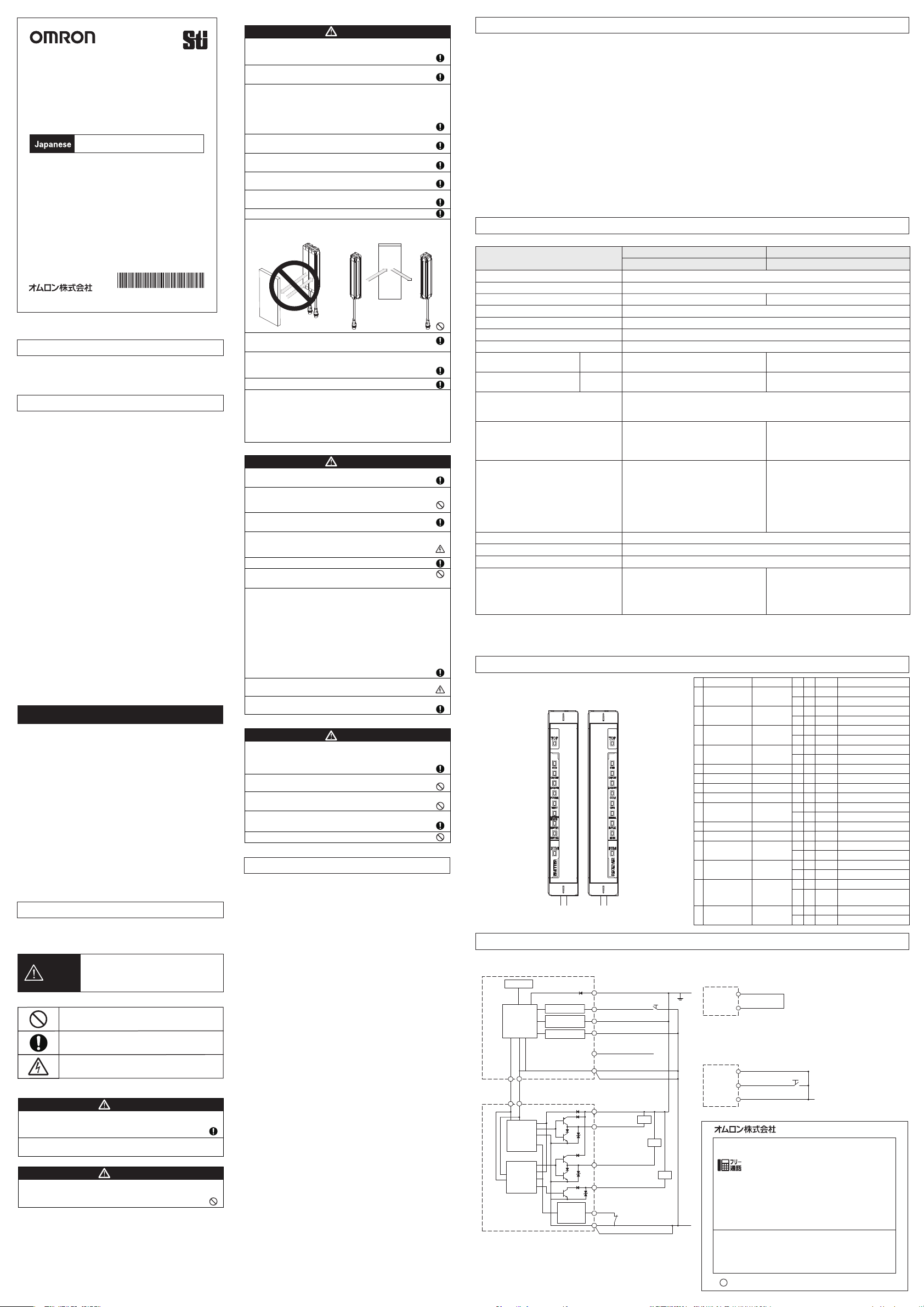
下図のようにミラーを使用した回帰反射型の配置では使用しないでくださ
い。検出不能状態になることがあります。ミラーで 検 出 エリアを 9 0 °曲げるこ
とは 問 題 ありません。
反射板
反射板
回帰反射型の配置
全てのF3SJ-E/Bに対してユーザーズマニュアル「第5章チェックリスト」
に記載の点 検を実施してください 。
ミューティングセンサは通過させる物体と人体の区別が出来るように 配 置し
てください。人体に反応してミューティング機能が働いた場合、
重症を負う恐れがあります 。
検出エリアを90°曲げる配置
ミューティング入力には独立した2つの入力機器を使用してください 。
ミューティング 機 能お よび オ ー バーライド機能は装置の安全機能を無効にします。前記
の機能がはたらいているときの安全性については、別の手段にて確保してください 。
オーバーライドを起 動 するスイッチには 、バネ復帰式のキースイッチ などの ホールド・トゥ・
ラン装置を使 用し、危険エリア全体が見え、かつ危険エリア 内から 操 作 できない 位 置
に設置してください 。また 、オーバーライドは必ず危険エリアに 誰もいないことを 確 認し
てから起動してください。
配線について
警 告
負荷は出力と+24Vラインの間に接続してください(NPN出力)。誤って出力と
0Vラインの間に接続すると、動作モードが「しゃ光時ON」に反転して危 険です。
出力線を0Vラインに短 絡させない でください 。出力が常時ONとなり危険で
す。また、出力線の地絡によって出力がONとならないよう、電源の
+24V側を接地してください 。
必要な安全カテゴリの要求事項を満たすように適切な数の制御出力
を使用してシステムを構成してください 。
F3SJ-E/Bの各ラインをDC24V+20%を超えるDC電源に接続しないでく
ださい 。また、AC電源にも接続しないでください 。感電、もしくは破壊の
可能性があり危険です。
配線は、必ず電源OFFの状態で行ってください 。
補助出力を安全用途に使用しないでください 。
F3SJ-Bが故障しても人体が検出されず、重傷を負う恐れがあります 。
F3SJ-E/BがIEC61496-1およびUL508を満たすために、DC電源ユニットは下記の
項目すべてを満たすようにしてください 。
・定格の電源電圧内(DC24V±20%)である
・複数の装置に接続する場合には、各装置の総定格電流に対して余裕を持たせる。
・EMC指令適合(工業環境)
・一次回路、二次回路間が二重絶縁あるいは強化絶縁
・過電流保護特性が自動復帰
・出力保持時間が20ms以上
・
UL508で定義されるクラス2回路または制限電圧電流回路の出力特性要求を満たす。
・F3SJ-E/Bが使用される国、地域でのEMCと電気機器安全に関する法規・規格に
従う電 源 である。(例:EUではEMC指令、低電圧指令に適合の電源であること)
すべての入出力線は、危険電圧から二重絶縁あるいは強化絶縁に
より絶 縁されているようにしてください 。感電の可能性があり危険です。
コード延長は規定以内の長さとしてください 。安全機能が正常に働かない
可能性があり危険です。
その他
F3SJ-E/BをPSDIモード(センサによるサイクル 運転 の 再 始動 )で使用
するには、F3SJ-E/B と機械の間に適切な制御回路を構成する必要が
あります。PSDIについての詳細は、OSHA1910.217、IEC61496-1、
およびその他の関連する規格、規制を参照してください 。
本体を分解、修理、改造しないでください 。本来の安全機能が失われ
危険です。
F3SJ-E/Bを引火性、爆発性ガスの雰囲気中で使用しないでください 。
爆発の恐れがあります 。
F3SJ-E/Bの日常点検、6か月ごとの点検を必ず実施してください 。
システムが正常に動作せず、重傷を負う恐れがあります 。
警 告
F3SJ-E/Bの間近で携帯電話やトランシーバを 使 用しな い でください 。
安全上の要点
以下に示すような項目は安全を確保する上で必要なことですので必ず守って
ください 。
・次のような場所には設置しないでください 。
-直 射日光など、強い外乱光があたる場所
-湿度が高く、結露する恐れがある場所
-オイルミストや腐食性ガスがある場所
-仕様で定められる以上の振 動や衝 撃が本体に伝わる場所
-水がかかる場所
-汚染度3以上の場所
-接着剤を溶かすような油のかかる場所
・負荷は、下記の項目すべてを満たすようにし てください 。
-短絡させない
-定格以上の電流を流さない
・製品を落下させないでください 。
・投光器と受光器の上下方向を合わせて設置してください 。
・使用している国の該当する廃棄物処理規則に従って廃棄してください 。
・コードのコネクタを確実に締めてください 。
・コードのコネクタを 、他のコネクタに切り替える場合、コネクタ内 部の 導 体 が
IP54以上で保護される構造としてください 。
・高圧線や動力線とF3SJ-E/Bの入出力線を同一配管で使用しないでくださ
い。
・コードを専用コード以外で延長する場合、同 等以上の性 能のコードを使用して
ください 。
・コードを延長する際は、仕様で定められた長さ(最大30m)の範囲内で延長を
行ってください 。
・スパッタなどの 異 物が 付 着 す るような環境ではスパッタからF3SJ-E/Bを保護
するカバーを装着ください 。
・PCツール「SDManager」(形F39-GWUM)やセッティングコンソール ( 形
F39-MC21)はF3SJ-A専用の設定ツールです。F3SJ-E/Bにこれら設定ツ
ールを接 続して使 用しないでください 。
製品が動作不能、誤動作、または 性 能・機器への悪影響を防ぐため、以下のことを守ってください 。
■保管・設置環境について
・次のような場所には保管・設置しないでください 。
-仕様で定められる以上の温度、湿度での長時間の保管、使用
・本製品はクラスA機器です。家庭用環境において、本製品は電 波障害を起こすことが あります 。この場合は、責 任者が十 分な対策を講じてください 。
・F3SJ-E/Bを高度1000m以上で使用しないでください 。
■配線・取り付けに つ いて
・配線は、必ず電源OFFの状態で行ってください 。故障診断機能により、F3SJ-E/Bが動作しなくなることがあります。
・出力線を0Vラインに短 絡させたままにしないでください 。F3SJ-E/Bが故障する原因となります 。
・通信線を専用コード(形F39-JD□□)以外で延長する場合は、同等以 上の性能のコード(ツイストペア線 )を使用してください 。シールドは0Vラインへ接続してください 。
・すべての端子の信号名を確認し、正しく配線してください 。
・電源投入後に検出エリアに 何も無 い 状 態とし、安定表示灯が点灯することを確認してください 。
・制御システムは、F3SJ-E/Bの電源投入後2秒以上経過してから作動させてください 。
・市販のスイッチングレギュレータを使用する場合、FG(フレームグランド端 子)を接地してください 。
・検出幅が1105mmを超える場合、ユーザーズマニュアルに記載の外形寸法図にしたがい、規定の数量、および位置にて中間金具をご使用ください 。ご使 用されない 場
合、定格/性能
・強い高周波ノイズを発生する機器から離して設置してください 。あるいは遮蔽対策を十分に行ってください 。
・
他の機器と電源を共用することによってノイズの影響や電圧降下などの影響を受ける可能性があります 。他の機器と電源を共用せず、安全コンポ専用の電源とすることを 推 奨します 。
■清掃について
シンナ ー 、ベンジン、アセトン類は、樹脂部材やケース塗装を溶かしますので、使用しないでください 。
■検出体について
透明体、半透明体は検出できませ ん。
を満たすことが できません。
定格/性能
使用上の注意
形式中の□□□□には、検出幅(mm)が4桁の数字で入ります 。
項目
形式
最小検出物体
光軸ピッチ
検出幅(mm)
検出距離(m)
応答時間
電源投入後立ち上がり時間
電源電圧(Vs)
消費電流(無負荷時)
投光器
受光器
制御出力(OSSD)
補助出力
入力電圧
周囲温度
周囲湿度
保護構造
直列連結
*
1. 誘導性負荷の値は、制御出力が頻繁に ON/OFF を繰り返す場合の最大値です。制御出力を 4Hz 以下で使用する場合は使用できる誘導性負荷の値が
大きくなります。
*
2. 追加でコンデンサなどの容量性負荷を含む素子を接続する場合に考慮していただく値です。
*
3.ここでのVsとは使用環境での電圧値です。
不透明 直径25mm
20mm
185〜1105mm(8〜54光軸)
0.2〜7.0m
ON→OFF:15ms以下、OFF→ON:70ms以下
2s以下
SELV/PELV24VDC±20%(リップルp-p10%以下)
22光軸まで:41mA以下、26〜42光軸:57mA以下、
46〜54光軸:63mA以下
22光軸まで:40mA以下、26〜42光軸:45mA以下、
46〜54光軸:48mA以下
NPNトランジスタ出力x2、負荷電流200mA以下、残留電圧2V以下(コード延長による影響
除く)、漏れ電流1mA以下、誘導性負荷2.2H以下
許容容量負荷1μF
―
ON電圧:0V〜3V (短絡電流 約4.0mA)
OFF電圧:1/2Vs〜Vsまたはオープン*3
(短絡電流 約3.0mA)
動作時:-10〜55℃(ただし氷結しないこと)、保存時:-25〜70℃
動作時:35〜85%RH(ただし結露しないこと)、保存時:35〜95%RH
IP65(IEC60529)
―
Easyタイプ Basicタイプ
F3SJ-E□□□□N25 F3SJ-B□□□□N25
185〜2065mm(8〜102光軸)
22光軸まで:52mA以下、26〜42光軸:68mA以下、46〜62光軸:75mA以下、
66〜82光軸:88mA以下、86〜102光軸:101mA以下
22光軸まで:47mA以下、26〜42光軸:52mA以下、46〜62光軸:58mA以下、
66〜82光軸:63mA以下、86〜102光軸:69mA以下
*
*
2
1
NPNトランジスタ出力×1
負荷電流100mA以下
残留電圧2V以下(コード延長による影響除く)
漏れ電流1mA以下
テスト入力、インターロック選択入力、リセット
入力、ミューティング入力ともに
ON電圧:0V〜3V(短絡電流 約4.0mA)
OFF電圧:1/2Vs〜Vsまたはオープン*3
(短絡電流 約3.0mA)
外部リレーモニタ入力
ON電圧:0V〜3V(短絡電流 約5.5mA)
OFF電圧:オープン
・連結数:3セットまで(ただし、F3SJ-B同士のみになり
ます。他機種は接続できません。)
・総光軸数:192光軸まで
・連結されたセンサ間のコード長:最大7m(連結コード
(形F39-JBR2W)と本体のコードは含まない)
内部表示灯
点灯/点滅
説明
点灯
入光量が出力ONしきい値の170%以上
点滅
外乱光や振動による出力OFF
点灯
緑:出力ON、赤:出力OFF
点滅
出力関連のエラー
点灯
ロックアウト中
点滅
ロックアウト中 、エラー発生側
点灯
電源投入中
点滅
電源電圧/ノイズによるエラー
点滅
投光停止中
点滅
ミューティングエラー
点灯
ミューティング入力1がON
点灯
ミューティング入力2がON
点灯
投受光間の通信成立
点滅
通信のエラー
点滅
接続センサの形式構成がエラー
点滅
内部のエラー
点灯
インターロック中
点滅
入力配線がエラー
点灯
外部リレーモニタ入 力が O N
点滅
外部リレーモニタがエラー
点灯
最上端の光軸が入光している
点滅
ミューティング/オ ーバ ーライド中
キャップ未接続エラー、連結エラー
点灯
最下端の光軸が入光している
点滅
ミューティング/オ ーバ ーライド中
14.上端入光表示灯(青)
1.安定表示灯(緑)
2.ON/OFF出力表示灯(緑/赤)
3.ロックアウト表示灯(赤)
4.電源表示灯(緑)
5.テスト表示灯(緑)
6.ミューティングエラー表示灯(緑)
7.ミューティング入力1表示灯(緑)
8.ミューティング入力2表示灯(緑)
15.下端入光表示灯(青)
<投光器> <受光器>
14.上端入光表示灯(青)
1.安定表示灯(緑)
2.ON/OFF出力表示灯(緑/赤)
3.ロックアウト表示灯(赤)
9.通信表示灯(緑)
10.構成表示灯(緑)
11.内部エラー表示灯(赤)
12.インターロック表示灯(黄)
13.外部リレーモニタ表示灯(緑)
15.下端入光表示灯(青)
1
安定表示灯
2
ON/OFF出力表示灯
3
ロックアウト表示灯
4
電源表示灯
テスト表示灯
5
ミューティングエラー表示灯
6
ミューティング入力1表示灯
7
ミューティング入力2表示灯
8
通信表示灯
9
構成表示灯
10
内部エラー表示灯
11
インターロック表示灯
12
13
外部リレーモニタ表示灯
14
上端表示灯
15
下端表示灯
Easy
STB
ON/OFF
LOCKOUT
POWER
TEST
MUTINGERROR
MUTE1
MUTE2
COM
CFG
INTERNAL
INTERLOCK
EDM
TOP
BTM
Basic
○○
○○
○○
○○
○○
○○
○○
○○
○○
−○
−○
−○
○○
○○
○○
○○
−○
−○
−○
−○
○○
−○
○○
−○
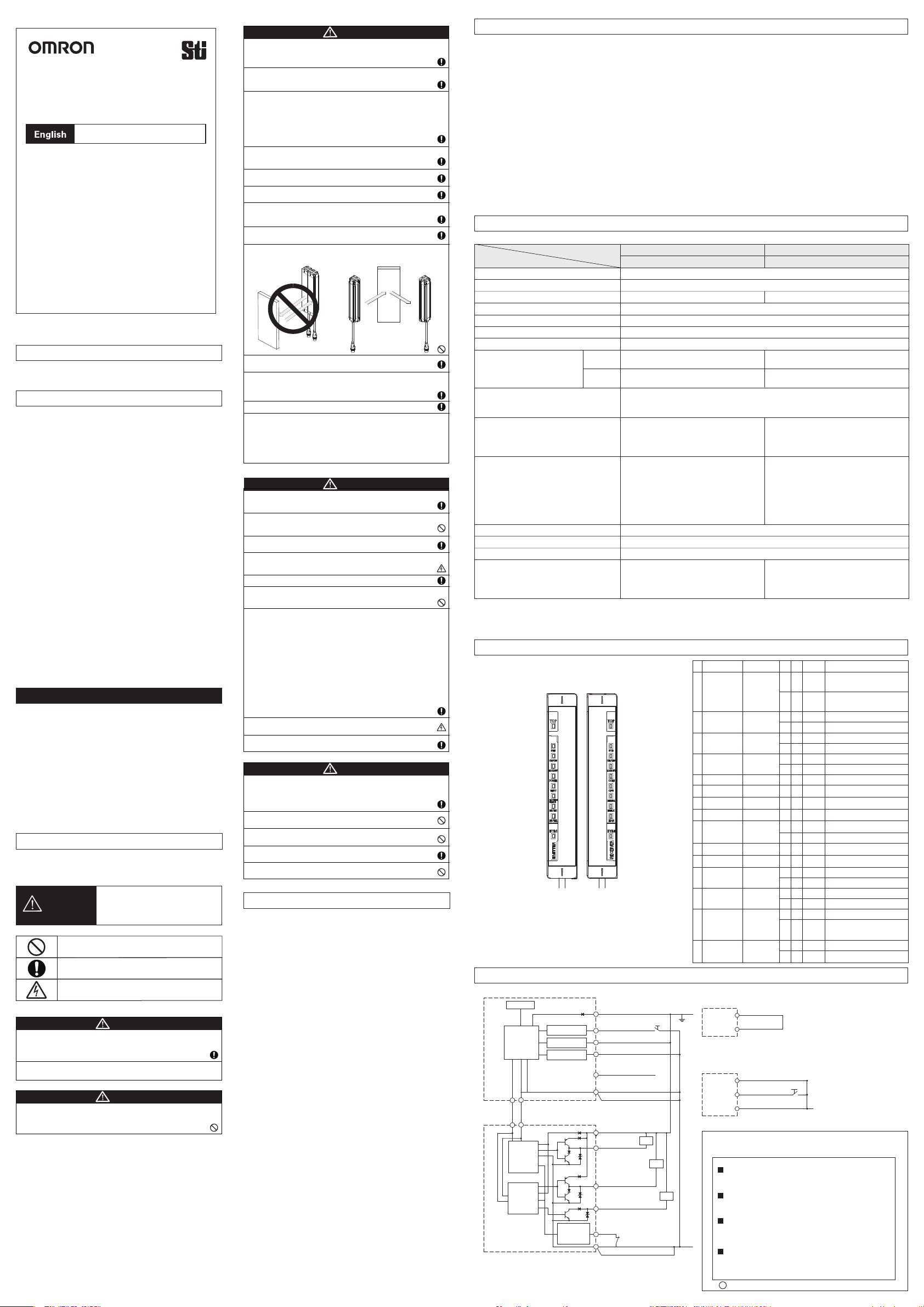
入出力回路
■オートリセットモード、外部リレーモニタ機能使用時の配線
表示灯
投光器
主回路
5
6
桃
灰
通信線(+) 通信線(‒)
5 6
受光器
主回路2
受光器
主回路1
Easyタイプには有りません
*
テスト入力回路
インターロック
選択入力回路
リセット入力 回 路
外部リレー
モニタ
入力回路
茶
2
黒テスト入力
3
白インターロック選択入力*
1
黄リセット入力*
4
赤未使用*
8
青
7
シールド*
茶
2
白制御出力2
1
黒制御出力1
3
黄補助出力*
4
赤外部リレーモニタ入力*
8
青
7
シールド*
+24VDC
負荷
負荷
負荷
■外部リレーモニタ機能を無効にする配線
外部リレーモニタ入力を補助出力へ短絡してください。
赤
外部リレーモニタ入力*
8
黄補助出力*
4
■インターロックマニュアルリセットに する配 線
インターロック選択入力とリセット入力を以下のとおりに配線してください 。
白インターロック選択入力*
1
黄リセット入力*
4
7
●製品に関するお問い合わせ先
お客様相談室
青 0V
リセットスイッチ
インダ ストリア ル オートメーションビジ ネス カ ン パ ニ ー
クイック オムロン
0120-919-066
携帯電話・PHS・IP電話などではご利用いただけませんので、下記の電話番号へおかけください 。
0V
電話
055-982-5015
■営業時間:8:00〜21:00 ■営業日:365日
●FAXやWebページでもお問い合わせいただけます。
FAX055-982-5051/www.fa.omron.co.jp
●その他のお問い合わせ
納期・価格・サンプル・仕様書は貴社のお取引先、または貴社
担当オムロン販売員にご相談ください。
オムロン制御機器販売店やオムロン販売拠点は、Webページで
ご案内しています。
v
A
2014年7月
(通話料がかかります)
Page 2
Original instructions
Model F3SJ-E□□□□N25
F3SJ-B□□□□N25
SAFETYLIGHTCURTAIN
INSTRUCTION SHEET
Please read and understand this instruction sheet before
storing, installing, programming, operating, maintaining, or
disposing of the products. Please consult your OMRON
representative if you have any questions or comments.
Please refer to the User's Manual and the Quick Installation
Manual for detailed instructions on usage.
OMRON Corporation
©
Instructions in the official EU languages and a signed EC
Declaration of Conformity in English are available on our website at
www.industrial.omron.eu/safety.
EC Declaration of Conformity
OMRON declares that F3SJ is in conformity with the requirements of the
following EC Directives:
Machinery Directive 2006/42/EC
EMC Directive 2014/30/EU
LEGISLATION AND STANDARDS
1. An F3SJ-E/B does not receive type approval provided by Article 44-2 of
the Labour Safety and Health Law of Japan. Therefore, the F3SJ-E/B
cannot be used as a "safety system for pressing or shearing machines"
prescribed in Article 42 of that law.
2.
The F3SJ-E/B is electro-sensitive protective equipment (ESPE) in accordance
with European Union (EU) Machinery Directive Index Annex V, Item 2.
3. The F3SJ-E/B is in conformity with the following standards:
(1) European standards
EN 61496-1 (Type 4 ESPE), CLC/TS 61496-2 (Type 4 AOPD),
EN 61508-1 through -3 (SIL3), EN 61000-6-4,
EN ISO 13849-1:2008 (Category 4, PL e)
(2) International standards
IEC 61496-1 (Type 4 ESPE), IEC 61496-2 (Type 4 AOPD),
IEC 61508-1 through -3 (SIL3), ISO 13849-1:2006 (Category 4, PLe)
(3) JIS standards
JIS B 9704-1 (Type 4 ESPE), JIS B 9704-2 (Type 4 AOPD)
(4) North American Standards:
UL 61496-1 (Type 4 ESPE), UL 61496-2 (Type 4 AOPD), UL 508,
UL 1998, CAN/CSA C 22.2 No.14, CAN/CSA C 22.2 No.08
4. The F3SJ-E/B received the approvals of EC Type-Examination in
accordance with the EU Machinery Directive, Type 4 ESPE and Type 4
AOPD from the EU accredited body, TÜV SÜD Product Service GmbH.
5.
The F3SJ-E/B received the certificates of UL listing for US and Canadian
safety standards, Type 4 ESPE and Type 4 AOPD from the Third Party
Assessment Body UL.
6. The F3SJ-E/B is designed according to the standards listed below. To make
sure that the final system complies with the following standards and
regulations, you are asked to design and use it in accordance with all other
related standards, laws, and regulations. If you have any questions, consult
with specialized organizations such as the body responsible for prescribing
and/or enforcing machinery safety regulations in the location where the
equipment is to be used.
•European Standards: EN415-4, EN692, EN693
•U.S. Occupational Safety and Health Standards: OSHA 29 CFR 1910.212
•U.S. Occupational Safety and Health Standards: OSHA 29 CFR 1910.217
•American National Standards: ANSI B11.1 to B11.19
•American National Standards: ANSI/RIA 15.06
•Canadian Standards Association CSA Z142, Z432, Z434
•SEMI Standards SEMI S2
•Japan Ministry of Health, Labour and Welfare "Guidelines for
Comprehensive Safety Standards of Machinery", Standard Bureau's
Notification No. 0731001 dated July 31, 2007.
Omron Companies shall not be responsible for conformity with any
standards, codes or regulations which apply to the combination of the Product
in the Buyer’ s application or use of the Product. At Buyer’ s request, Omron
will provide applicable third party certification documents identifying ratings
and limitations of use which apply to the Product. This information by itself
is not sufficient for a complete determination of the suitability of the Product
in combination with the end product, machine, system, or other application or
use. Buyer shall be solely responsible for determining appropriateness of the
particular Product with respect to Buyer’ s application, product or system.
Buyer shall take application responsibility in all cases.
NEVER USE THE PRODUCT FOR AN APPLICATION INVOLVING
SERIOUS RISK TO LIFE OR PROPERTY OR IN LARGE QUANTITIES
WITHOUT ENSURING THAT THE SYSTEM AS A WHOLE HAS BEEN
DESIGNED TO ADDRESS THE RISKS, AND THAT THE OMRON
PRODUCT(S) IS PROPERLY RATED AND INSTALLED FOR THE
INTENDED USE WITHIN THE OVERALL EQUIPMENT OR SYSTEM.
PRECAUTIONS ON SAFETY
Regarding the alert symbols and meanings used for the safe uses
In order to use the F3SJ-E/B safely, the precautions listed in this Instruction
Sheet indicated by alert symbols and descriptions must be followed. Failure
to follow all precautions and alerts may result in an unsafe use or operation.
The following indications and symbols are used for the descriptions.
WARNING
Meanings of Alert Symbols
Alert Statements in this Manual
For Users
The F3SJ-E/B must be installed, configured, and incorporated into a
machine control system by a sufficiently trained and qualified person. An
unqualified person may not be able to perform these operations properly,
which may cause a person to go undetected, resulting in serious injury.
Thoroughly read this manual and understand the installation procedures, operation
check procedures, and maintenance procedures before using the product.
For Machines
Do not use this sensor for machines that cannot be stopped by electrical
control. For example, do not use it for a pressing machine that uses
full-rotation clutch. Otherwise, the machine may not stop before a
personreaches the hazardous part, resulting in serious injury.
2011-2018
All Rights Reserved.
Suitability for Use
Indicates a potentially hazardous situation
which, if not avoided, will result in minor or
moderate injury, or may result in serious
injury or death. Additionally there may be
significant property damage.
Indicates prohibited actions.
Indicates mandatory actions.
Indicates the risk of electric shock.
WARNING
WARNING
For Installation
WARNING
Make sure to test the operation of the F3SJ-E/B after installation to verify
that the F3SJ-E/B operates as intended. Make sure to stop the machine
until the test is complete. Unintended function settings may
cause a person to go undetected, resulting in serious injury.
Make sure to install the F3SJ-E/B at the safe distance from the hazardous part
of the equipment. Otherwise, the machine may not stop before
a person reaches the hazardous part, resulting in serious injury.
Install a protective structure so that the hazardous part of a machine can only be
reached by a person that passes through the sensor's detection zone. Install the
sensors so that part of the person is always present in the detection zone when
working in a machine's hazardous zones, eliminating areas where the sensors do
not reach. If a person is able step into the hazardous zone of a machine and
remain behind the F3SJ-E/B's detection zone, configure the system with an
interlock function that prevents the machine from being restarted.
Failure to do so may result in serious injury.
Install the interlock reset switch in a location that provides a clear view
of the entire hazardous zone and where it cannot be activated
from within the hazardous zone.
The F3SJ-E/B cannot protect a person from a projectile exiting
the hazardous zone. Install protective cover(s) or fence(s).
Install the F3SJ-E/B so that it is not affected by a reflective surface.
Failure to do so may hinder detection, resulting in serious injury.
When using more than one set of F3SJ-E/Bs, install them so that mutual
interference does not occur, such as by configuring series
connections or using physical barriers between adjacent sets.
Make sure that the F3SJ-E/B is securely mounted and its cables
and connectors are properly secured.
Do not use the sensor system with mirrors in a retro-reflective
configuration as shown below. Doing so may hinder detection. It is
possible to use mirrors to "bend" the detection zone to a 90-degree angle.
Reflector
Reflector
Position with retro-reflection
Perform an inspection for all F3SJ-E/B as described in
"Chapter 5 Checklists" in the User's Manual.
Install muting sensors so that they can distinguish between the object that
is being allowed to be passed through the detection zone and a person. If
the muting function is activated by the detection of a person,
it may result in serious injury.
Position with detection zone
bent at 90°
Use independent two input devices for muting inputs.
The muting and override functions disable the safety functions of the
device.You must ensure safety using other method when these functions are
operating.A switch to activate the override function must be a hold-to-run
device such as a spring return key switch and must be installed in a location
that provides a clear view of the entire hazardous zone and where it cannot
be activated from within the hazardous zone.Make sure that nobody is in the
hazardous zone before activating the override function.
For Wiring
WARNING
Connect the load between the output and +24 V line (NPN output). Connecting
the load between the output and 0 V line will result in a dangerous
condition because operation is reversed to "ON when blocked".
Do not short-circuit the output line to the 0 V line. Otherwise, the output is
always ON. Also, the +24 V of the power supply must be grounded
so that output does not turn ON due to grounding of the output line.
Configure the system by using the optimal number of safety outputs
that satisfy the requirements of the necessary safety category.
Do not connect each line of F3SJ-E/B to a DC power supply of more than
24 VDC+20%. Also, do not connect to an AC power supply.
Failure to do so may result in electric shock or breakdown of the device.
Make sure to perform wiring while the power supply is OFF.
Do not use the auxiliary output for safety applications.
A person may go undetected even if F3SJ-B is out of order, resulting in
serious injury.
For the F3SJ-E/B to comply with IEC61496-1 and UL508, the DC power
supply unit must satisfy all of the following conditions:
• Must be within the rated power voltage (24 V DC ± 20%)
• Must have tolerance against the total rated current of devices if it is
connected to multiple devices
• Must comply with EMC directives (industrial environment)
• Double or reinforced insulation must be applied between the primary and
secondary circuits
• Automatic recovery of overcurrent protection characteristics
• Output holding time must be 20ms or longer
• Must satisfy output characteristic requirements for class 2 circuit or
limited voltage current circuit defined by UL508
• Must comply with laws and regulations, regarding EMC and electrical
equipment safety, of the country or region where the F3SJ-E/B is used
(Ex: In EU, the power supply must comply with the EMC Directive
and the Low Voltage Directive.)
Double or reinforced insulation from hazardous voltage must be applied
to all input and output lines. Failure to do so may result in electric shock.
Extension of the cable must be within a specified length. If it isn't,
safety function may not work properly, resulting in danger.
Other
WARNING
To use the F3SJ-E/B in PSDI mode (Reinitiation of cyclic operation by
the protective equipment), you must configure an appropriate circuit
between the F3SJ-E/B and the machine. For details about PSDI, refer to
OSHA1910.217, IEC61496-1, and other relevant standards
and regulations.
Do not try to disassemble, repair, or modify this product.
Doing so may cause the safety functions to stop working properly.
Do not use the F3SJ-E/B in environments where flammable or
explosive gases are present. Doing so may result in explosion.
Perform daily and 6-month inspections for the F3SJ-E/B. Otherwise,
the system may fail to work properly, resulting in serious injury.
Do not use radio equipment such as cellular phones, walkie-talkies,
or transceivers near the F3SJ-E/B.
PRECAUTIONS FOR SAFE USE
Make sure to observe the following precautions that are necessary for
ensuring safe use of the product.
• Do not install the F3SJ-E/B in the following types of environments:
-Areas exposed to intense interference light, such as direct sunlight
-Areas with high humidity where condensation is likely to occur
-Areas where oil mist or corrosive gases are present
-Areas exposed to vibration or shock levels higher than in the specification
provisions
-Areas where the product may come into contact with water
-Areas with pollution degree 3
-Areas where the product may get wet with oil that can solve adhesive
• Loads must satisfy both of the following conditions:
-Not short-circuited
-Not used with a current that is higher than the rating
• Do not drop the product.
• Install the emitter and receiver to the same vertical direction.
• Dispose of the product in accordance with the relevant rules and regulations
of the country or area where the product is used.
• Make sure to tighten the connectors of the cables securely.
• When replacing the cable connectors with other types of connectors, use
connectors that provide a protection grade of IP54 or higher.
• Be sure to route the input/output lines for the F3SJ-E/B separate from
high-potential power lines or through an exclusive conduit.
• To extend a cable length with a cable other than the dedicated cable, use
cable with the same or superior specifications.
• The cable extension length must be within the specified length (30 m max).
• In environments where foreign material such as spatter adheres to the
F3SJ-E/B, attach a cover to protect the F3SJ-E/B from the spatter.
• F39-GWUM SD Manager Setting Support Software and F39-MC21 Setting
Console are the setting tools dedicated for F3SJ-A. Do not connect these
tools to F3SJ-E/B.
Observe the precautions described below to prevent operation failure, malfunctions, or undesirable effects on product performance.
■Storage conditions and installation environment
• Do not install, use, or store the F3SJ-E/B for a long time at a temperature or humidity out of the specified range.
• This is a class A product. In residential areas it may cause radio interference, in which case the Responsible Person may be required to take adequate measures to
reduce interference.
• Do not use radio equipment such as cellular phones, walkie-talkies, or transceivers near the F3SJ-E/B.
• Do not use F3SJ-E/B at altitudes over 1,000 meters.
■Wiring and installation
• Make sure to perform wiring while the power supply is OFF. Otherwise, the F3SJ-E/B may fail to operate due to the diagnosis function.
• Do not short-circuit output lines to 0 V line. Otherwise a fault of the F3SJ-E/B may occur.
• When extending the communication line with a cable (twisted-pair wire) other than the dedicated cable (F39-JD□□), use a cable with the same or superior
specifications. Connect the shield to the 0V line.
• Be sure that there is nothing in the detection zone and the stable-state indicator is turned ON after power is turned ON.
• Properly perform the wiring after confirming the signal names of all the terminals.
• Do not operate the control system until 2 seconds or more after turning ON the power of the F3SJ-E/B.
• Be sure to route the F3SJ-E/B cable separate from high-potential power lines or through an exclusive conduit.
• When using a commercially available switching regulator power supply, make sure to ground the FG terminal (frame ground terminal).
If the protective height is more than 1105mm, use Intermediate Brackets of specified quantities and locations according to the dimensions described in the User's Manual.
•
• Do not install the F3SJ-E/B close to a device that generates high-frequency noise. Otherwise, take sufficient blocking measures.
• Sharing the power supply with other devices may cause the F3SJ-E/B to be affected by noise or voltage drop. It is recommended that the F3SJ-E/B use a dedicated
power supply but do not share with other devices.
■Cleaning
Do not use thinner, benzene, or acetone for cleaning, because they affect the product's resin parts and paint on the extrusion.
■Object detection
The F3SJ-E/B cannot detect transparent and/or translucent objects.
RATINGS
PRECAUTIONS FOR CORRECT USE
The model names of the F3SJ-E/B contain the 4 digits indicating the protective height (mm).
Item
Model
Detection capability
Beam gap
Protective height (mm)
Response time
Operating range (m)
Startup waiting time
Power supply voltage (Vs)
Current consumption (with no load)
Emitter
Receiver
Safety output (OSSD)
Auxiliary output
Input voltage
Ambient temperature
Ambient humidity
Degree of protection
Cascade connection
*1. The load inductance is the maximum value when the safety output frequently repeats ON and OFF. When you use the safety output at 4 Hz or less,
the usable load inductance becomes larger.
*2. These values must be taken into consideration when connecting elements including a capacitive load such as capacitor.
*3. The Vs in this case indicates a voltage value in usage environment.
Opaque objects, 25 mm diameter
20 mm
185 to 1,105 mm (8 to 54 beams)
ON to OFF: 15 ms max, OFF to ON: 70 ms max.
0.2 to 7.0 m
2 s max.
SELV/PELV 24 VDC±20% (ripple p-p 10% max.)
Up to 22 beams: 41 mA max., 26 to 42 beams: 57 mA max.,
46 to 54 beams: 63 mA max.
Up to 22 beams: 40 mA max., 26 to 42 beams: 45 mA max.,
46 to 54 beams: 48 mA max.
Two NPN transistor outputs, Load current: 200 mA max., Residual voltage: 2 V max.
(except for voltage drop due to cable extension), Leakage current: 1 mA max., Load
inductance: 2.2 H max. *1
Maximum capacitive load: 1 µF *2
—
Test input:
ON voltage: 0 to 3 V
(short circuit current: approx. 4.0 mA)
OFF voltage: 1/2 Vs to Vs, or open *3
(short circuit current: approx. 3.0 mA)
Operating: -10 to 55°C (non-icing), storage: -25 to 70°C
Operating: 35% to 85% (non-condensing), storage: 35% to 95%
IP65 (IEC 60529)
—
Easy Type Basic Type
F3SJ-E□□□□N25 F3SJ-B□□□□N25
185 to 2,065 mm (8 to 102 beams)
Up to 22 beams: 52 mA max., 26 to 42 beams: 68 mA max., 46 to 62 beams: 75 mA max.,
66 to 82 beams: 88 mA max., 86 to 102 beams: 101 mA max.
Up to 22 beams: 47 mA max., 26 to 42 beams: 52 mA max., 46 to 62 beams: 58 mA max.,
66 to 82 beams: 63 mA max., 86 to 102 beams: 69 mA max.
One NPN transistor output
Load current: 100 mA max.
Residual voltage: 2 V max.(except for voltage
drop due to cable extension)
Leakage current: 1 mA max.
Test input, Interlock select input, Reset input, Muting input:
ON voltage: 0 to 3 V
(short circuit current: approx. 4.0 mA)
OFF voltage:1/2 Vs to Vs, or open *3
(short circuit current: approx. 3.0 mA)
External device monitoring input:
ON voltage: 0 to 3 V
(short circuit current: approx. 5.5 mA)
OFF voltage: Open
• Number of cascaded segments: 3 max. (only among
F3SJ-B's. Other models cannot be connected.)
• Total number of beams: 192 max.
• Cable length between sensors: 7 m max. (Connection
cable (F39-JBR2W) and sensor's cable are not included.)
Internal Indicator
ON/
Description
Blinking
Turns ON when incidence level is
ON
170% or more of the output ON
threshold.
Blinks when the safety output is
Blinking
turned OFF due to disturbance
light or vibration.
Green: Output ON, Red: Output OFF
ON
Output related error
Blinking
ON
During lockout
Blinking
During lockout, error occurrence side
ON
When power is ON
Blinking
Error due to power supply voltage/noise
Blinking
During emission stoppage
Blinking
Muting error
ON
Muting input 1 is ON
ON
Muting input 2 is ON
When communication between
ON
emitter and receiver is established.
Blinking
Communication error
Model configuration of the connected
Blinking
sensor is in error
Blinking
Internal error
ON
During interlock
Blinking
Input wiring error
ON
External device monitoring input is ON
Blinking
External device monitoring error
ON
Top beam is receiving light
During muting/override
Blinking
Cap disconnection error
sensor connection error
ON
Bottom beam is receiving light
Blinking
During muting/override
14. Top-beam-state indicator (Blue)
1. Stable-state indicator (Green)
2. ON/OFF-state indicator (Green/Red)
3. Lockout indicator (Red)
4. Power indicator (Green)
5. Test indicator (Green)
6. Muting error indicator (Green)
7. Muting input 1 indicator (Green)
8. Muting input 2 indicator (Green)
15. Bottom-beam-state indicator (Blue)
Emitter Receiver
14. Top-beam-state indicator (Blue)
1. Stable-state indicator (Green)
ON/OFF-state indicator (Green/Red)
2.
3. Lockout indicator (Red)
9. Communication indicator (Green)
10. Configuration indicator (Green)
11. Internal error indicator (Red)
12. Interlock indicator (Yellow)
13. External device monitoring
indicator (Green)
15.
Bottom-beam-state indicator (Blue)
Stable-state
1
indicator
ON/OFF
output-state
2
indicator
Lockout
3
indicator
Power
4
indicator
Test indicator
5
Muting error
6
indicator
Muting input 1
7
indicator
Muting input 2
8
indicator
Communication
9
indicator
Configuration
10
indicator
Internal error
11
indicator
Interlock
12
indicator
External device
monitoring
13
indicator
Top-beam-state
14
indicator
Bottom-
15
beam-state
indicator
STB
ON/OFF
LOCKOUT
POWER
TEST
MUTING
ERROR
MUTE1
MUTE2
COM
CFG
INTERNAL
INTERLOCK
EDM
TOP
BTM
Easy Basic
○○
○○
○○
○○
○○
○○
○○
○○
○○
−○
−○
−○
○○
○○
○○
○○
−○
−○
−○
−○
○○
−○
○○
−○
Input/Output Circuit
■Wiring for auto reset mode and external device monitoring function
Indication
Emitter
Main
Circuit
5
Gray
Communication
line (+)
5 6
Receiver
Main
Circuit 2
Receiver
Main
Circuit 1
Not available for Easy type.
*
6
Pink
Communication
line (-)
Test Input
Circuit
Interlock Select
Input Circuit
Reset Input
Circuit
External
Device
Monitoring
Input Circuit
2
3
1
4
8
7
2
1
3
4
8
7
Brown
Black
White
Yellow
Red
Blue
Brown
White
Black
Yellow
Red
Blue
Test input
Interlock select input*
Reset input*
Not used*
Shield*
Safety
Load
output 2
Safety output 1
Auxiliary output*
External device
monitoring input*
Shield*
Load
Load
■Wiring to disabl e ext e rnal de vic e moni t oring func t ion
Short-circ ui t t he ext e rnal de vic e moni t oring i nput to t he auxiliary output.
+24 VDC
■Wiring for interlock and manual reset mode
Perform wiring for interlock select input and reset input as follows.
0 V
Red External device monitoring input*
8
Yellow
Auxiliary output
4
White
Interlock select input
1
Yellow Reset input
4
Blue 0 V
7
OMRON Corporation Industrial Automation Company(Manufacturer)
Shiokoji Horikawa, Shimogyo-ku, KYOTO, 600-8530 JAPAN
Regional Headquarters
OMRON EUROPE B.V.(Representative and Importer in EU)
Wegalaan 67-69, NL-2132 JD Hoofddorp
THE NETHERLANDS
Tel: (31) 2356-81-300/Fax: (31) 2356-81-388
OMRON ELECTRONICS LLC
2895 Greenspoint Parkway, Suite 200
Hoffman Estates, IL 60169 U.S.A.
Tel: (1) 847-843-7900/Fax: (1) 847-843-7787
OMRON ASIA PACIFIC PTE. LTD.
No. 438A Alexandra Road # 05-05/08 (Lobby 2),
Alexandra T echnopark,
Singapore 119967
Tel: (65) 6835-3011/Fax: (65) 6835-2711
OMRON (CHINA) CO., LTD.
Room 2211, Bank of China Tower,
200 Yin Cheng Zhong Road,
PuDong New Area, Shanghai, 200120, China
Tel: (86) 21-5037-2222/Fax: (86) 21-5037-2200
s
Oct, 2014
D
*
*
*
Reset switch
Contact: www.ia.omron.com
 Loading...