

Page 1
Safety Light Curtain
F3SJ-B N25-01T Series
User's Manual
Cat. No. SCHG-735E
Page 2

Original instructions
Introduction
Thank you for purchasing the F3SJ-B Series Safety Light Curtain (hereinafter referred to as the "F3SJ-B").
This is the instruction manual describing the use of F3SJ-B.
Always heed the following points when using the F3SJ-B:
Be sure to have F3SJ-B be handled by a "Responsible Person" who is well aware of and familiar with the machine to be installed.
The term "Responsible Person" used in this User's Manual means the person qualified, authorized and responsible to secure
"safety" in each process of the design, installation, operation, maintenance services and disposition of the machine.
It is assumed that F3SJ-B will be used properly according to the installation environment, performance and function of the machine.
Responsible Person should conduct risk assessment on the machine and determine the suitability of this product before installation.
Read this Manual thoroughly to understand and make good use of the descriptions before installing and operating the product.
Keep this Manual at the place where the operator can refer to whenever necessary.
Page 3

Legislation and Standards
1. An F3SJ-B does not receive type approval provided by Article 44-2 of the Industrial Safety and Health Act
of Japan. Therefore, the F3SJ-B cannot be used as a "safety system for pressing or shearing machines"
prescribed in Article 42 of that law.
2. The F3SJ-B is electro-sensitive protective equipment (ESPE) in accordance with European Union (EU)
Machinery Directive Index Annex V, Item 2.
3. EC Declaration of Conformity
OMRON declares that the F3SJ-B is in conformity with the requirements of the following EC Directives:
Machinery Directive 2006/42/EC
EMC Directive 2014/30/EU
4. The F3SJ-B is in conformity with the following standards:
(1)European standards
EN 61496-1 (Type 4 ESPE), EN 61496-2 (Type 4 AOPD), EN 61508-1 through -3 (SIL3),
EN 61000-6-4, EN ISO 13849-1:2015 (Category 4, PL e)
(2)International standards
IEC 61496-1 (Type 4 ESPE), IEC 61496-2 (Type 4 AOPD), IEC 61508-1 through -3 (SIL3),
ISO 13849-1: 2015 (Category 4, PL e)
(3)JIS standards
JIS B 9704-1 (Type 4 ESPE), JIS B 9704-2 (Type 4 AOPD)
(4)North American Standards:
UL 61496-1 (Type 4 ESPE), UL 61496-2 (Type 4 AOPD), UL 508, UL 1998, CAN/CSA C22.2 No.14,
CAN/CSA C22.2 No.0.8
Introduction
5. The F3SJ-B received the approvals of EC Type-Examination in accordance with the EU Machinery
Directive, Type 4 ESPE and Type 4 AOPD from the EU accredited body,
6. The F3SJ-B received the certificates of UL listing for US and Canadian safety standards, Type 4 ESPE and
Type 4 AOPD from the Third Party Assessment Body UL.
7. The F3SJ-B is designed according to the standards listed below. To make sure that the final system
complies with the following standards and regulations, you are asked to design and use it in accordance
with all other related standards, laws, and regulations. If you have any questions, consult with specialized
organizations such as the body responsible for prescribing and/or enforcing machinery safety regulations in
the location where the equipment is to be used.
•European Standards: EN415-4, EN692, EN693
•U.S. Occupational Safety and Health Standards: OSHA 29 CFR 1910.212
•U.S. Occupational Safety and Health Standards: OSHA 29 CFR 1910.217
•American National Standards: ANSI B11.1 to B11.19
•American National Standards: ANSI/RIA 15.06
•Canadian Standards Association CSA Z142, Z432, Z434
•SEMI Standards SEMI S2
•Japan Ministry of Health, Labour and Welfare "Guidelines for Comprehensive Safety Standards of
Machinery", Standard Bureau's Notification No. 0731001 dated July 31, 2007.
TÜV SÜD
Product Service GmbH.
F3SJ-B
User’s Manual
E
i
Page 4

Introduction
Terms and Conditions Agreement
Read and understand this catalog.
Please read and understand this catalog before purchasing the products. Please consult your OMRON representative if
you have any questions or comments.
Warranties.
(a) Exclusive Warranty. Omron's exclusive warranty is that the Products will be free from defects in materials and
workmanship for a period of twelve months from the date of sale by Omron (or such other period expressed in writing
by Omron). Omron disclaims all other warranties, express or implied.
(b) Limitations. OMRON MAKES NO WARRANTY OR REPRESENTATION, EXPRESS OR IMPLIED, ABOUT NON-
INFRINGEMENT, MERCHANTABILITY OR FITNESS FOR A PARTICULAR PURPOSE OF THE PRODUCTS.
BUYER ACKNOWLEDGES THAT IT ALONE HAS DETERMINED THAT THE PRODUCTS WILL SUITABLY MEET
THE REQUIREMENTS OF THEIR INTENDED USE.
Omron further disclaims all warranties and responsibility of any type for claims or expenses based on infringement by the
Products or otherwise of any intellectual property right. (c) Buyer Remedy. Omron's sole obligation hereunder shall be, at
Omron's election, to (i) replace (in the form originally shipped with Buyer responsible for labor charges for removal or
replacement thereof) the non-complying Product, (ii) repair the non-complying Product, or (iii) repay or credit Buyer an
amount equal to the purchase price of the non-complying Product; provided that in no event shall Omron be responsible
for warranty, repair, indemnity or any other claims or expenses regarding the Products unless Omron's analysis confirms
that the Products were properly handled, stored, installed and maintained and not subject to contamination, abuse, misuse
or inappropriate modification. Return of any Products by Buyer must be approved in writing by Omron before shipment.
Omron Companies shall not be liable for the suitability or unsuitability or the results from the use of Products in
combination with any electrical or electronic components, circuits, system assemblies or any other materials or
substances or environments. Any advice, recommendations or information given orally or in writing, are not to be
construed as an amendment or addition to the above warranty.
See http://www.omron.com/global/
or contact your Omron representative for published information.
Limitation on Liability; Etc.
OMRON COMPANIES SHALL NOT BE LIABLE FOR SPECIAL, INDIRECT, INCIDENTAL, OR CONSEQUENTIAL
DAMAGES, LOSS OF PROFITS OR PRODUCTION OR COMMERCIAL LOSS IN ANY WAY CONNECTED WITH THE
PRODUCTS, WHETHER SUCH CLAIM IS BASED IN CONTRACT, WARRANTY, NEGLIGENCE OR STRICT LIABILITY.
Further, in no event shall liability of Omron Companies exceed the individual price of the Product on which liability is
asserted.
Suitability of Use.
Omron Companies shall not be responsible for conformity with any standards, codes or regulations which apply to the
combination of the Product in the Buyer's application or use of the Product. At Buyer's request, Omron will provide
applicable third party certification documents identifying ratings and limitations of use which apply to the Product. This
information by itself is not sufficient for a complete determination of the suitability of the Product in combination with the
end product, machine, system, or other application or use. Buyer shall be solely responsible for determining
appropriateness of the particular Product with respect to Buyer's application, product or system. Buyer shall take
application responsibility in all cases.
NEVER USE THE PRODUCT FOR AN APPLICATION INVOLVING SERIOUS RISK TO LIFE OR PROPERTY WITHOUT
ENSURING THAT THE SYSTEM AS A WHOLE HAS BEEN DESIGNED TO ADDRESS THE RISKS, AND THAT THE
OMRON PRODUCT(S) IS PROPERLY RATED AND INSTALLED FOR THE INTENDED USE WITHIN THE OVERALL
EQUIPMENT OR SYSTEM.
Programmable Products.
Omron Companies shall not be responsible for the user's programming of a programmable Product, or any consequence
thereof.
F3SJ-B
ii
User’s Manual
Page 5

Performance Data.
Data presented in Omron Company websites, catalogs and other materials is provided as a guide for the user in
determining suitability and does not constitute a warranty. It may represent the result of Omron's test conditions, and the
user must correlate it to actual application requirements. Actual performance is subject to the Omron's Warranty and
Limitations of Liability.
Change in Specifications.
Product specifications and accessories may be changed at any time based on improvements and other reasons. It is our
practice to change part numbers when published ratings or features are changed, or when significant construction
changes are made. However, some specifications of the Product may be changed without any notice. When in doubt,
special part numbers may be assigned to fix or establish key specifications for your application. Please consult with your
Omron's representative at any time to confirm actual specifications of purchased Product.
Errors and Omissions.
Information presented by Omron Companies has been checked and is believed to be accurate; however, no responsibility
is assumed for clerical, typographical or proofreading errors or omissions.
Introduction
F3SJ-B
User’s Manual
E
iii
Page 6
Introduction
Precautions on Safety
Regarding the alert symbols and meanings used for the safe uses
In order to use the F3SJ-B safely, the precautions listed in this manual indicated by alert symbols and
descriptions must be followed. Failure to follow all precautions and alerts may result in an unsafe use or
operation.
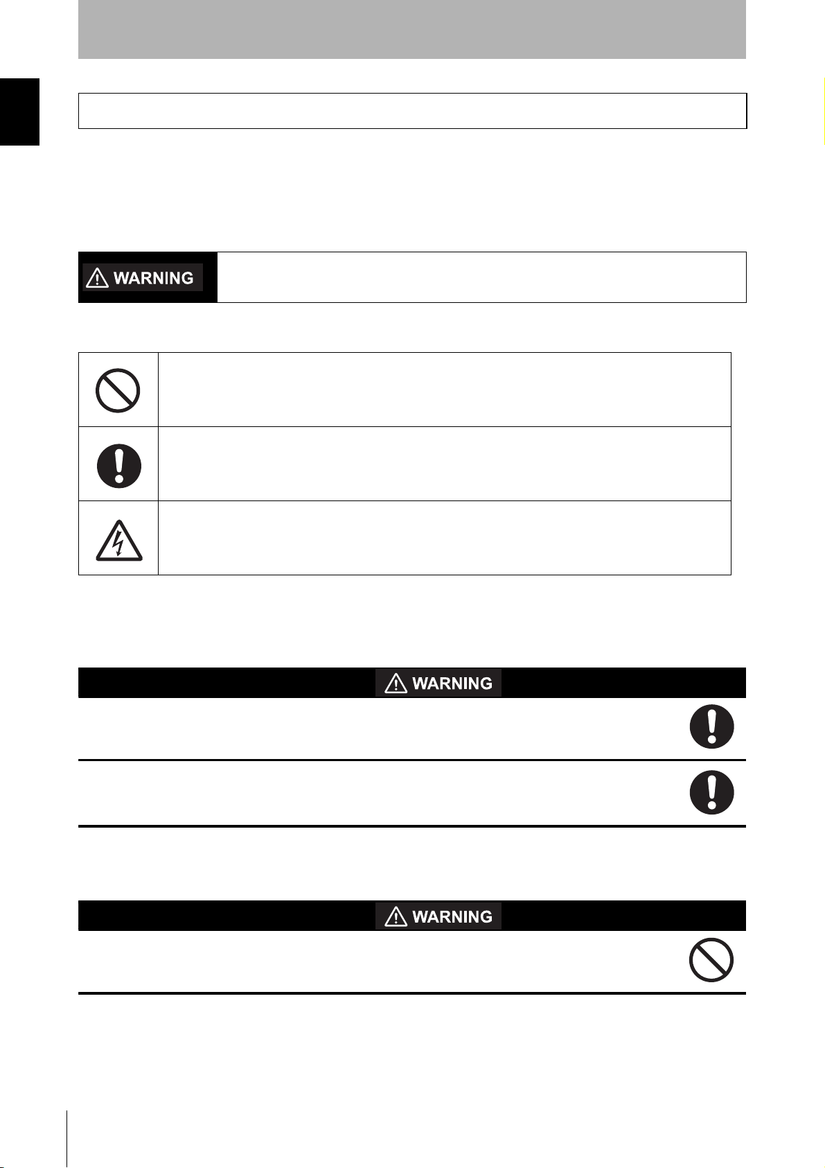
The following indications and symbols are used for the descriptions.
Indicates a potentially hazardous situation which, if not avoided, will result in minor or moderate injury, or
may result in serious injury or death. Additionally there may be significant property damage.
Meanings of Alert Symbols
Indicates prohibited actions.
Indicates mandatory actions.
Indicates the risk of electric shock.
Alert Statements in this Manual
For users
The F3SJ-B must be installed, configured, and incorporated into a machine control system by a
sufficiently trained and qualified person. An unqualified person may not be able to perform these
operations properly, which may cause a person to go undetected, resulting in serious injury.
Read this manual thoroughly and understand the procedures of installation, operation check and
maintenance.
For machines
iv
Do not use this sensor for machines that cannot be stopped by electrical control. For example,
do not use it for a pressing machine that uses full-rotation clutch. Otherwise, the machine may
not stop before a person reaches the hazardous part, resulting in serious injury.
F3SJ-B
User’s Manual
Page 7
For installation
Reflector
Position with retro-reflection
Position with detection zone bent at 90°
Reflector
Make sure to test the operation of the F3SJ-B after installation to verify that the F3SJ-B operates
as intended. Make sure to stop the machine until the test is complete. Unintended function
settings may cause a person to go undetected, resulting in serious injury.
Make sure to install the F3SJ-B at the safe distance from the hazardous part of the equipment.
Otherwise, the machine may not stop before a person reaches the hazardous part, resulting in
serious injury.
Install a protective structure so that the hazardous part of a machine can only be reached by a
person that passes through the sensor's detection zone. Install the sensors so that part of the
person is always present in the detection zone when working in a machine's hazardous zones,
eliminating areas where the sensors do not reach. If a person is able step into the hazardous
zone of a machine and remain behind the F3SJ-B's detection zone, configure the system with an
interlock function that prevents the machine from being restarted. Failure to do so may result in
serious injury.
Install the interlock reset switch in a location that provides a clear view of the entire hazardous
zone and where it cannot be activated from within the hazardous zone.
Introduction
The F3SJ-B cannot protect a person from a projectile exiting the hazardous zone. Install
protective cover(s) or fence(s).
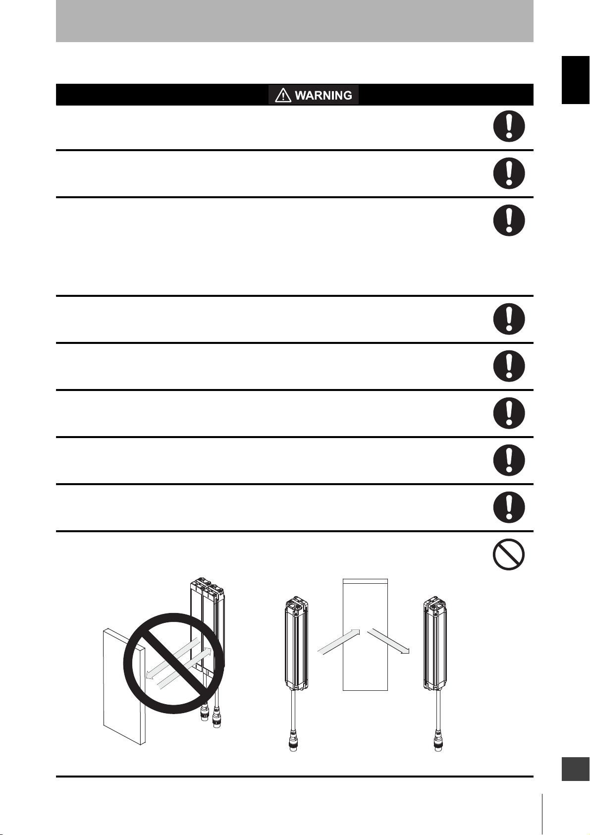
Install the F3SJ-B so that it is not affected by a reflective surface. Failure to do so may hinder
detection, resulting in serious injury. Details on installation distance from the reflective surface,
see "Distance from Reflective Surfaces" on page 23.
When using more than one set of F3SJ-Bs, install them so that mutual interference does not
occur, such as by configuring series connections or using physical barriers between adjacent
sets.
Make sure that the F3SJ-B is securely mounted and its cables and connectors are properly
secured.
Do not use the sensor system with mirrors in a retro-reflective configuration as shown below.
Doing so may hinder detection. It is possible to use mirrors to "bend" the detection zone to a 90degree angle.
F3SJ-B
User’s Manual
E
v
Page 8
Introduction
Perform an inspection for all F3SJ-B as described in "Chapter 5 Checklists".
For wiring
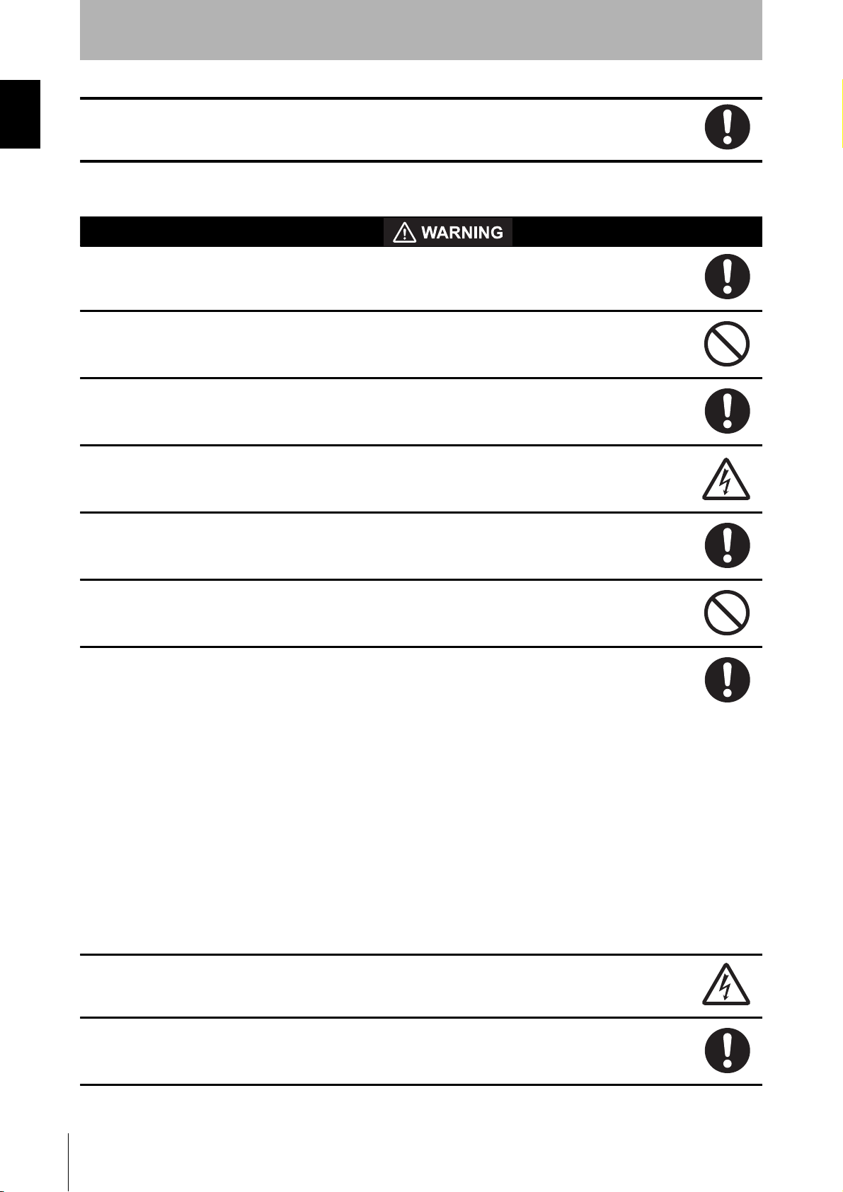
Connect the load between the output and +24 V line (NPN output). Connecting the load between
the output and 0 V line will result in a dangerous condition because operation is reversed to "ON
when blocked".
Do not short-circuit the output line to the 0 V line. Otherwise, the output is always ON. Also, the
+24 V of the power supply must be grounded so that output does not turn ON due to grounding
of the output line.
Configure the system by using the optimal number of safety outputs that satisfy the requirements
of the necessary safety category.
Do not connect each line of F3SJ-B to a DC power supply of more than 24 VDC+20%. Also, do
not connect to an AC power supply. Failure to do so may result in electric shock or breakdown of
the device.
Make sure to perform wiring while the power supply is OFF.
Do not use the auxiliary output for safety applications. Human body may not be detected when
F3SJ-B fails, resulting in serious injury.
For the F3SJ-B to comply with IEC 61496-1 and UL 508, the DC power supply unit must satisfy
all of the following conditions:
• Must be within the rated power voltage (24 VDC
± 20%)
• Must have tolerance against the total rated current of devices if it is connected to multiple
devices
• Must comply with EMC directives (industrial environment)
• Double or reinforced insulation must be applied between the primary and secondary circuits
• Automatic recovery of overcurrent protection characteristics
• Output holding time must be 20 ms or longer
• Must satisfy output characteristic requirements for class 2 circuit or limited voltage current circuit
defined by UL 508. Refer to p.65 for details.
• Must comply with laws and regulations, regarding EMC and electrical equipment safety, of the
country or region where the F3SJ-B is used (Ex: In EU, the power supply must comply with the
EMC Directive and the Low Voltage Directive.)
vi
Double or reinforced insulation from hazardous voltage must be applied to all input and output
lines. Failure to do so may result in electric shock.
Extension of the cable must be within a specified length. If it isn't, safety function may not work
properly, resulting in danger.
F3SJ-B
User’s Manual
Page 9
Other
To use the F3SJ-B in PSDI mode (Reinitiation of cyclic operation by the protective equipment),
you must configure an appropriate circuit between the F3SJ-B and the machine. For details
about PSDI, refer to OSHA1910.217, IEC 61496-1, and other relevant standards and
regulations.
Do not try to disassemble, repair, or modify this product. Doing so may cause the safety functions
to stop working properly.
Do not use the F3SJ-B in environments where flammable or explosive gases are present. Doing
so may result in explosion.
Perform daily and 6-month inspections for the F3SJ-B. Otherwise, the system may fail to work
properly, resulting in serious injury.
Do not use radio equipment such as cellular phones, walkie-talkies, or transceivers near the
F3SJ-B.
Introduction
F3SJ-B
User’s Manual
E
vii
Page 10

Introduction
Precautions for Safe Use
Make sure to observe the following precautions that are necessary for ensuring safe use of the product.
Do not install the F3SJ-B in the following types of environments:
- Areas exposed to intense interference light, such as direct sunlight
- Areas with high humidity where condensation is likely to occur
- Areas where oil mist or corrosive gases are present
- Areas exposed to vibration or shock levels higher than in the specification provisions
- Areas where the product may come into contact with water
- Areas with pollution degree 3 or harsher
- Areas where the product may get wet with oil that can solve adhesive
• Loads must satisfy both of the following conditions:
- Not short-circuited
- Not used with a current that is higher than the rating
• Do not drop the product.
• Install the emitter and receiver to the same vertical direction.
• Dispose of the product in accordance with the relevant rules and regulations of the country or area where the
product is used.
• Make sure to tighten the connectors of the cables securely.
• When replacing the cable connectors with other types of connectors, use connectors that provide a
protection grade of IP54 or higher.
• Be sure to route the input/output lines for the F3SJ-B separate from high-potential power lines or through an
exclusive conduit.
• To extend a cable length with a cable other than the dedicated cable, use a cable with the same or superior
specifictions.
• The cable extension length must be within the specified length (30 m max).
• In environments where foreign material such as spatter adheres to the F3SJ-B, attach a cover to protect the
F3SJ-B from the spatter.
• PC Setting Support Software "SD Manager" (F39-GWUM) and Setting Console (F39-MC21) are available
only for F3SJ-A series. Do not use these setting tools for F3SJ-B series.
viii
Precautions for Correct Use
Observe the precautions described below to prevent operation failure, malfunctions, or undesirable effects on
product performance.
Storage conditions and installation environment
•Do not install, use, or store the F3SJ-B for a long time at a temperature or humidity out of the specified
range.
•This is a class A product. In residential areas it may cause radio interference, in which case the
Responsible Person may be required to take adequate measures to reduce interference.
•F3SJ-B can be used at altitudes up to 2,000 meters.
Wiring and installation
•Make sure to perform wiring while the power supply is OFF. Otherwise, the F3SJ-B may fail to operate
due to the diagnosis function.
•Do not short-circuit output lines to 0 V line. Otherwise a fault of F3SJ-B may occur.
F3SJ-B
User’s Manual
Page 11

•
When extending the communication line with a cable (twisted-pair wire) other than the dedicated cable
(F39-JD
•Properly perform the wiring after confirming the signal names of all the terminals.
•Be sure that there is nothing in the detection zone and the stable-state indicator is turned ON after
power is turned ON.
•Do not operate the control system until 2 seconds or more after turning ON the power of the F3SJ-B.
•Be sure to route the F3SJ-B cable separate from high-potential power lines or through an exclusive
conduit.
•When using a commercially available switching regulator power supply, make sure to ground the FG
terminal (frame ground terminal).
•If the protective height is more than 1,105 mm, use intermediate brackets of specified quantities and
locations according to the dimensions.
If the brackets described above are not used, ratings and performance cannot be met.
•Do not install the F3SJ-B close to a device that generates high-frequency noise. Otherwise, take
sufficient blocking measures.
•Sharing the power supply with other devices may cause the
voltage drop. It is recommended that this safety component use a dedicated power supply but do not
share with other devices.
), use a cable with the same or superior specifications. Connect the shield to the 0V line.
Cable specification (extension cable) p.69
F3SJ-E/B
to be affected by noise or
Introduction
Cleaning
Do not use thinner, benzene, or acetone for cleaning, because they affect the product's resin parts and
paint on the extrusion.
Object detection
The F3SJ-B cannot detect transparent and/or translucent objects.
F3SJ-B
User’s Manual
E
ix
Page 12

Introduction
F3SJ-B
x
User’s Manual
Page 13

Contents
Legislation and Standards i
Terms and Conditions Agreement ii
Precautions on Safety iv
Precautions for Safe Use viii
Precautions for Correct Use viii
Chapter1 Overview and Specifications 1
Basic Configuration and Names 2
Model Overview 3
Internal (LED) Indicator Display Pattern 4
Ratings/Specifications 6
Model/Current Consumption List 8
Chapter2 System Configuration and Functions 9
Introduction
Wiring Diagrams 10
Minimum wiring required to check the operation of the F3SJ-B 10
Wiring in use 11
Description of Functions 12
External Test Function 12
Self-test Function 13
Lockout Reset Function 14
Auxiliary Output Function 15
Chapter3 Wiring/Installation 17
Installation Conditions 18
Detection Zone and Approach 18
Safety Distance 19
Distance from Reflective Surfaces 23
Mutual Interference Prevention 23
Series Connection 25
Connection Procedure 27
Dimensions 28
When Using Top/Bottom and Intermediate Brackets 29
When Using Intermediate Brackets Only (Free-Location Mounting) 33
When Using One-touch Brackets 37
When Using Replacement Brackets 42
When Using Contact Mount Brackets 45
When Using Spatter Protection Cover 48
F3SJ-B
User’s Manual
E
xi
Page 14

Introduction
Mounting 49
Mounting Method 49
Number of Brackets Required 49
Mounting Procedure 50
Wiring 64
Wiring Precautions 64
Power Supply Unit 65
Wiring Method 66
Chapter4 Input/Output Circuit and Applications 71
Input/Output Circuit 72
Entire circuit diagram 72
Wiring Examples 73
Using F3SJ-B Only 73
Connecting a F3SJ-B to Various Controllers 74
Using a simple wiring connector for F3SJ-B 75
Chapter5 Checklists 77
Pre-Operation Checklists 78
Checklists 78
Maintenance Checklists 80
Checklists 80
Chapter6 Appendix 83
Troubleshooting 84
Lockout State 84
Warning View 84
Troubleshooting Methods 86
Optional Accessories (Sold Separately) 89
Glossary 94
Related Standards 95
International Standards 95
European Standards 95
US Occupational Safety and Health Standards 95
xii
F3SJ-B
User’s Manual
US Standards 95
Canadian Standards 96
SEMI Standards 96
JIS Standards 96
Page 15

Chapter1 Overview and Specifications
Basic Configuration and Names 2
Model Overview 3
Internal (LED) Indicator Display Pattern 4
Ratings/Specifications 6
Model/Current Consumption List 8
Chapter1 Overview and Specifications
F3SJ-B
User’s Manual
E
1
Page 16
Overview and Specifications
Basic Configuration and Names
Chapter1 Basic Configuration and Names
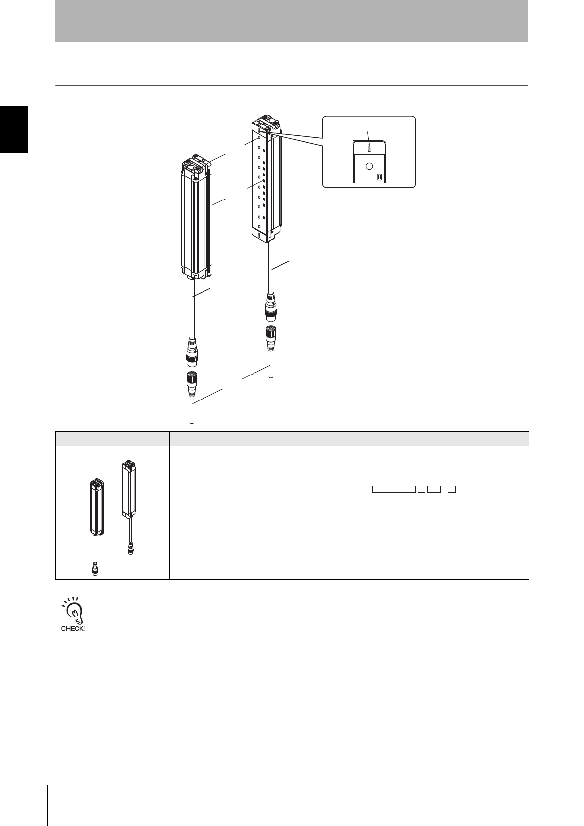
This section describes the system configuration and part names of the F3SJ-B.
Beam center-line mark
Beam
Receiver
Indicator
Emitter
Connection cable
(Black)
Connection
cable (Gray)
Extension cable
Component Model Description
Emitter, receiver F3SJ-BN25--01T Select a type name based on the required protective height.
The model name can be understood as follows:
F3SJ-B
1: Protective height (mm)
2: Output type (N for NPN output type *1)
3. Detection capability (mm)
4: L for emitter, D for receiver, blank for a set of emitter and receiver.
*1. A hyphen "-" is added instead of "N" for emitter.
To distinguish between the emitter and receiver, find the labels attached to the front of the F3SJ-B. The label on the emitter
reads "EMITTER" and the label on the receiver reads "RECEIVER".
□□□□
1 4 3 2
N25
-□-01T
F3SJ-B
2
User’s Manual
Page 17

Model Overview
Overview and Specifications
Functions:external test, lockout reset, auxiliary output and series connection.
Chapter1 Model Overview
F3SJ-B
User’s Manual
E
3
Page 18
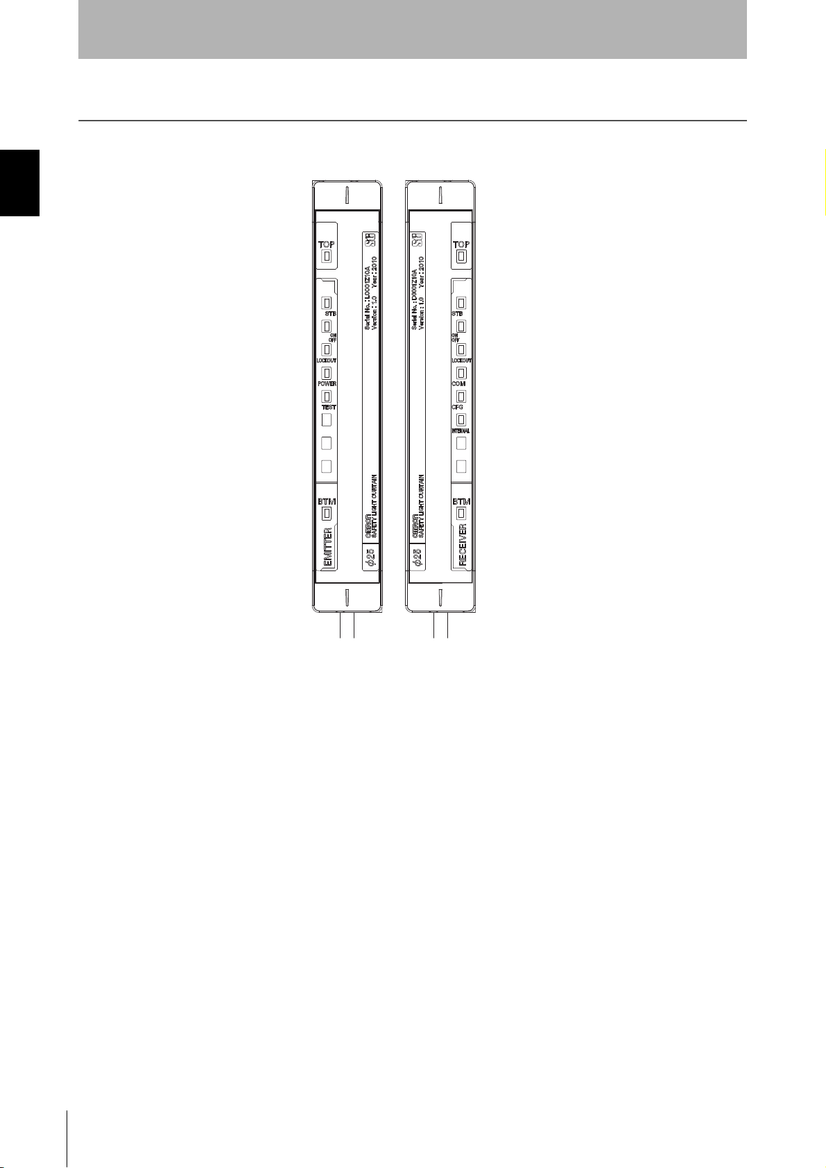
Chapter1 Internal (LED) Indicator Display Pattern
10. Bottom-beam-state indicator (Blue)
6. Test indicator (Green)
5. Power indicator (Green)
4. Lockout indicator (Red)
3. ON/OFF-state indicator (Green/Red)
2. Stable-state indicator (Green)
1. Top-beam-state indicator (Blue)
4. Lockout indicator (Red)
3. ON/OFF-state indicator (Green/Red)
2. Stable-state indicator (Green)
1. Top-beam-state indicator (Blue)
7. Internal error indicator (Red)
6. Configuration indicator (Green)
5. Communication indicator (Green)
Emitter
Receiver
10. Bottom-beam-state indicator (Blue)
Overview and Specifications
Internal (LED) Indicator Display Pattern
F3SJ-B
4
User’s Manual
Page 19
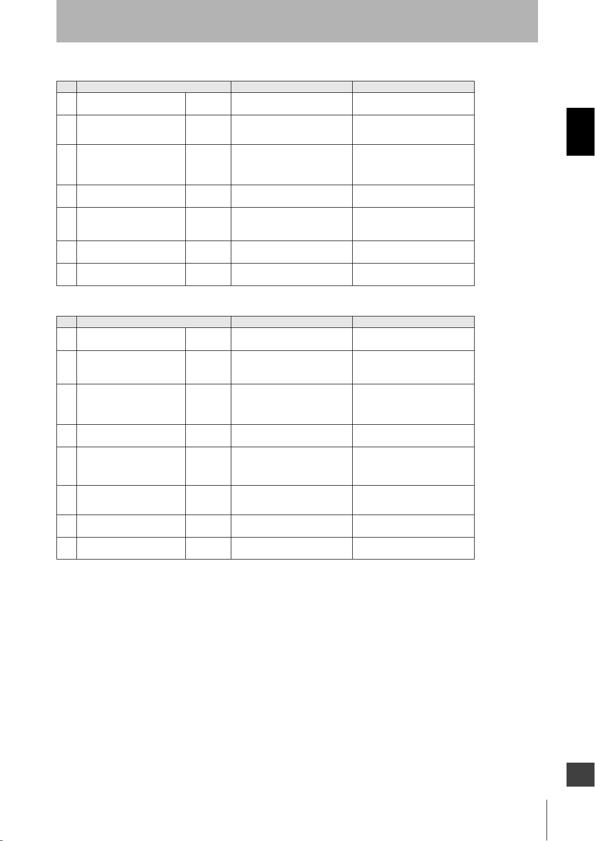
Overview and Specifications
Emitter
No. Internal indicator ON Blinking
1 Top-beam-state indicator TOP
2 Stable-state indicator STB
3 ON/OFF-state indicator
4 Lockout indicator LOCKOUT
5 Power indicator POWER
6 Test indicator TEST –
10 Bottom-beam-state indicator BTM
ON
OFF
Turns ON when the top beam is
receiving light.
Turns ON when incidence level is
170% or more of the output ON
threshold.
Green: Turns ON when safety
output is ON.
Red: Turns ON when safety
output is OFF.
Turns ON when the F3SJ-B
enters a lockout on the receiver.
Turns ON while the power of the
emitter is ON.
Turns ON when the bottom beam
is receiving light.
Receiver
No. Internal indicator ON Blinking
1 Top-beam-state indicator TOP
2 Stable-state indicator STB
3 ON/OFF-state indicator
4 Lockout indicator LOCKOUT
5 Communication indicator COM
6 Configuration indicator CFG –
7 Internal error indicator INTERNAL –
10 Bottom-beam-state indicator BTM
ON
OFF
Turns ON when the top beam is
receiving light.
Turns ON when incidence level
is 170% or more of the output
ON threshold.
Green: Turns ON when safety
output is ON.
Red: Turns ON when safety
output is OFF.
Turns ON when the F3SJ-B
enters a lockout on the emitter.
Turns ON when communication
between emitter and receiver is
established.
Turns ON when the bottom beam
is receiving light.
Blinks when cap error or
connection error occurs.
Blinks when the safety output is
turned OFF due to disturbance
light or vibration.
Red: Blinks when the F3SJ-B
enters a lockout due to a
safety output error.
Blinks when the F3SJ-B enters a
lockout on the emitter.
Blinks when the F3SJ-B enters a
lockout due to power voltage/
noise.
Blinks when external test is being
performed.
–
Blinks when cap error or
connection error occurs.
Blinks when the safety output is
turned OFF due to disturbance
light or vibration.
Red: Blinks when the F3SJ-B
enters a lockout due to a
safety output error.
Blinks when the F3SJ-B enters a
lockout on the receiver.
Blinks when the F3SJ-B enters
lockout due to a communication
error between receiver and
emitter.
Blinks when the F3SJ-B enters
lockout due to a model type error
between receiver and emitter.
Blinks when the F3SJ-B enters a
lockout due to an internal error.
–
Chapter1 Internal (LED) Indicator Display Pattern
F3SJ-B
User’s Manual
E
5
Page 20
Overview and Specifications
Ratings/Specifications
Chapter1 Ratings/Specifications
The model names of the F3SJ-B contain the 4 digits indicating the protective height (mm).
Model
Item
Detection capability
Beam gap 20 mm
Number of beams 8 to 102
Protective height 185 to 2,065 mm
Lens diameter 5 mm
Operating range 0.2 to 7 m
Response time
Startup waiting time 2 s max.
Power supply voltage (Vs) SELV/PELV 24 VDC±20% (ripple p-p 10% max.)
Current consumption
Light source Infrared LED (870 nm wavelength)
Effective aperture angle (EAA)
Safety output (OSSD)
Auxiliary output
Output operation mode
Input voltage
Overvoltage category II (IEC 60664-1)
Indicator
Opaque objects
25 mm diameter
ON to OFF: 15 ms max. (Response time when used alone or in 2 or 3 connected)
OFF to ON: 70 ms max. (Response time when used alone or in 2 or 3 connected)
Refer to "Model/Current Consumption List" on page 8.
Based on IEC 61496-2.
Within ±2.5° for both emitter and receiver at an operating range of 3 meters or more.
Two NPN transistor outputs, Load current: 200 mA max., Residual voltage: 2 V max.
(except for voltage drop due to cable extension), Leakage current: 1 mA max., Load
inductance: 2.2 H max. *1
Maximum capacitive load: 1 µF *2
One NPN transistor output
Load current: 100 mA max.
Residual voltage: 2 V max.(except for voltage drop due to cable extension)
Leakage current: 1 mA max.
Safety output: On when receiving light
Auxiliary output: Reverse output of safety output
Test input:
ON voltage: 1/2 Vs to Vs, or open *3 (short circuit current: approx. 3.0 mA)
OFF voltage: 0 V to 3 V (short circuit current: approx. 4.0 mA)
Reset input:
ON voltage: 0 V to 3 V (short circuit current: approx. 4.0 mA)
OFF voltage: 1/2 V to Vs, or open *3 (short circuit current: approx. 3.0 mA)
Refer to "Internal (LED) Indicator Display Pattern" on page 4.
F3SJ-BN25-01T
Mutual interference prevention function Mutual interference prevention algorithm prevents interference in up to three sets.
Number of connections: Up to three sets
Series connection function
Test function
*1. The load inductance is the maximum value when the safety output frequently repeats ON and OFF. When you use the safety
output at 4 Hz or less, the usable load inductance becomes larger.
*2. These values must be taken into consideration when connecting elements including a capacitive load such as a capacitor.
*3. The Vs indicates a voltage value in your environment.
F3SJ-B
6
User’s Manual
Total number of beams: Up to 192
Maximum connection cable length: 7 m (connection cable (F39-JBR2W) and F3SJ's
cable are not included)
Self-test (at power-on, and during operation)
External test (light emission stop function by test input)
Page 21
Overview and Specifications
Model
Item
Protection circuit Output short-circuit protection, and power supply reverse polarity protection
Ambient temperature During operation: -10 to 55°C (non-freezing), During storage: -25 to 70°C
Ambient humidity During operation: 35 to 85%RH (non-condensing), During storage: 35 to 95%RH
Ambient light intensity
Insulation resistance 20 MΩ or higher (500 VDC)
Dielectric strength 1,000 VAC, 50/60 Hz, 1 min
Degree of protection IP65 (IEC 60529)
Vibration resistance
Shock resistance Malfunction: 100 m/s
Pollution degree Pollution degree 3 (IEC 60664-1)
Connection
method
Power cable
Series connection cable
(F39-JBR2W)
Extension cable
(F39-JDA, JDB)
Extension cable 30 m max.
Material
Weight (packaged) F3SJ-BN25-01T
Accessories Quick Installation Manual(QIM), Instruction manual
Applicable standards
Number of wires 8 wires
Cable diameter Dia. 6 mm
Allowable
bending radius
Connection
method
Number of wires 8 wires
Cable diameter Dia. 6 mm
Allowable
bending radius
Connection
method
Number of wires 8 wires
Cable diameter Dia. 6.6 mm
Allowable
bending radius
Incandescent lamp: 3,000 lx max. on receiving surface. Sunlight: 10,000 lx max. on
receiving surface.
Malfunction: 10 to 55 Hz, Multiple amplitude of 0.7 mm, 20 sweeps each in X, Y, and Z
directions
2
, 1,000 times each in X, Y, and Z directions
Prewired connector cable, cable length 0.3 m
Connector type (M12, 8-pin)
Connector: IP67 rated (when mated)
R5 mm
Prewired connector cable, cable length 0.2 m
Connector type (M12, 8-pin)
Connector: IP67 rated (when mated)
R5 mm
Connector method (M12, 8-pin)
IP67 degree of protection for connector (fitting)
For details about twisted pair wires (single-ended cable) p.66, (double-ended
cable) p.67
For details about total extension cable length
R36 mm
Case: Aluminum
Cap: ABS resin, PBT
Optical cover: PMMA resin (acrylic)
Cable: Oil resistant PVC
Weight (g) = (protective height) x 2.7 + 500
Refer to "Legislation and Standards" on page i.
F3SJ-BN25-01T
Chapter1 Ratings/Specifications
Safety-related characteristic data
(EN 61508:2010)
See http://www.fa.omron.co.jp/safety_6en/
F3SJ-B
User’s Manual
E
7
Page 22

Overview and Specifications
Model/Current Consumption List
Chapter1 Ratings/Specifications
Model
F3SJ-BN25-01T Emitter Receiver
F3SJ-B0185N25-01T 8 185 41.0 mA 43.0 mA
F3SJ-B0225N25-01T 10 225 43.0 mA 43.0 mA
F3SJ-B0305N25-01T 14 305 46.0 mA 44.0 mA
F3SJ-B0385N25-01T 18 385 49.0 mA 46.0 mA
F3SJ-B0465N25-01T 22 465 52.0 mA 47.0 mA
F3SJ-B0545N25-01T 26 545 55.0 mA 48.0 mA
F3SJ-B0625N25-01T 30 625 58.0 mA 49.0 mA
F3SJ-B0705N25-01T 34 705 62.0 mA 50.0 mA
F3SJ-B0785N25-01T 38 785 65.0 mA 51.0 mA
F3SJ-B0865N25-01T 42 865 68.0 mA 52.0 mA
F3SJ-B0945N25-01T 46 945 71.0 mA 53.0 mA
F3SJ-B1025N25-01T 50 1025 75.0 mA 54.0 mA
F3SJ-B1105N25-01T 54 1105 69.0 mA 55.0 mA
F3SJ-B1185N25-01T 58 1185 72.0 mA 57.0 mA
F3SJ-B1265N25-01T 62 1265 75.0 mA 58.0 mA
F3SJ-B1345N25-01T 66 1345 77.0 mA 59.0 mA
F3SJ-B1425N25-01T 70 1425 80.0 mA 60.0 mA
F3SJ-B1505N25-01T 74 1505 83.0 mA 61.0 mA
F3SJ-B1585N25-01T 78 1585 85.0 mA 62.0 mA
F3SJ-B1665N25-01T 82 1665 88.0 mA 63.0 mA
F3SJ-B1745N25-01T 86 1745 91.0 mA 64.0 mA
F3SJ-B1825N25-01T 90 1825 93.0 mA 65.0 mA
F3SJ-B1905N25-01T 94 1905 96.0 mA 67.0 mA
F3SJ-B1985N25-01T 98 1985 99.0 mA 68.0 mA
F3SJ-B2065N25-01T 102 2065 101.0 mA 69.0 mA
Number of beams Protective height [mm]
Current consumption
F3SJ-B
8
User’s Manual
Page 23

Chapter2 System Configuration and
Functions
Wiring Diagrams 10
Minimum wiring required to check the operation of the F3SJ-B 10
Wiring in use 11
Description of Functions 12
External Test Function 12
Self-test Function 13
Lockout Reset Function 14
Auxiliary Output Function 15
Chapter2 System Configuration and Functions
F3SJ-B
User’s Manual
E
9
Page 24
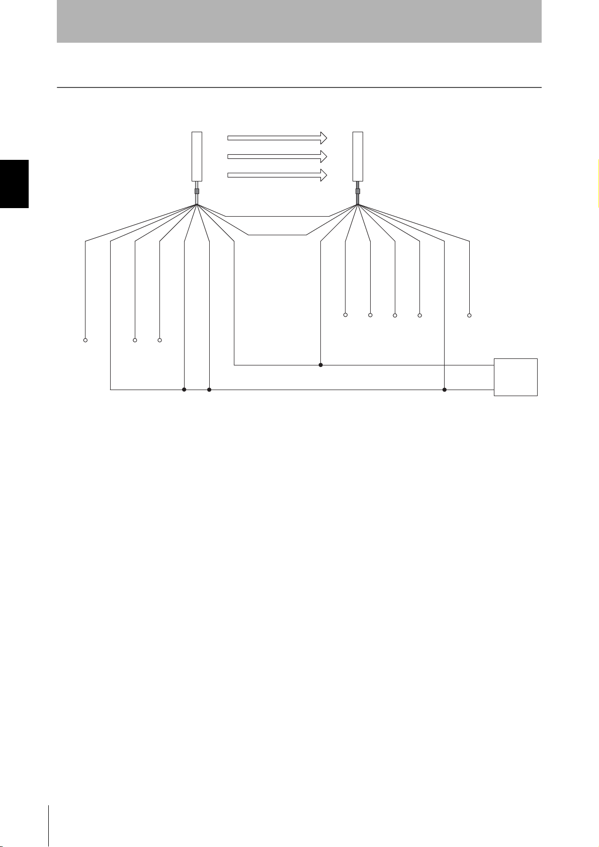
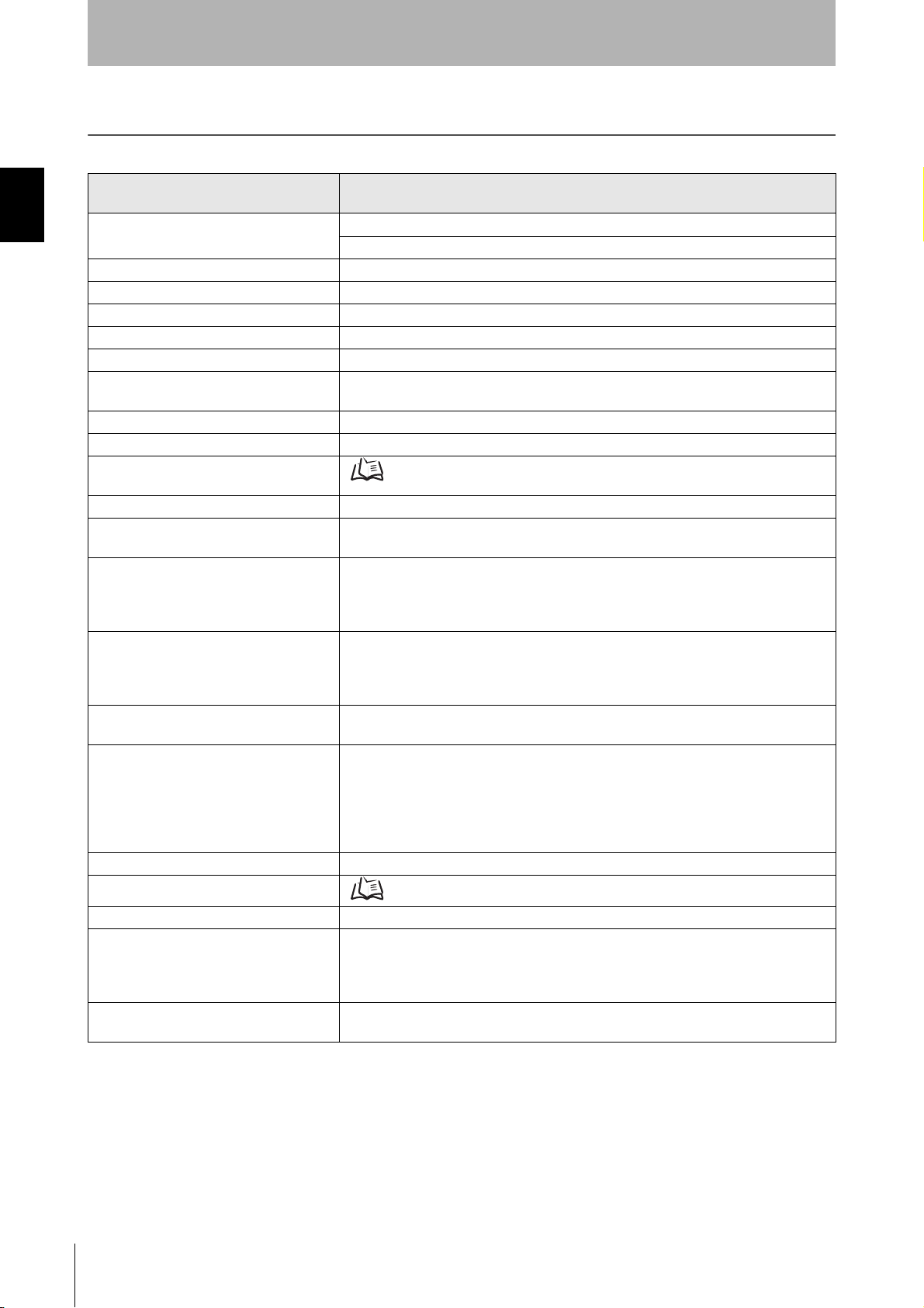
Chapter2 Wiring Diagrams
Open
Open
Open
0 V
Shield
Not Used (Red)
0 V (Blue)
Not Used (White)
Test input (Black)
Reset input (Yellow)
24 V (Brown)
Emitter
Receiver
(Gray) Communication line (+)
(Pink)
Communication line (-)
24 V (Brown)
Not Used
(Red)
0 V (Blue)
Auxiliary output (Yellow)
Safety output 1 (Black)
Safety output 2 (White)
Shield
Open
Open
Open
Power
supply
+24 VDC
F39-JDA-L F39-JDA-D
Open
Open
System Configuration and Functions
Wiring Diagrams
Minimum wiring required to check the operation of the F3SJ-B
10
F3SJ-B
User’s Manual
Page 25
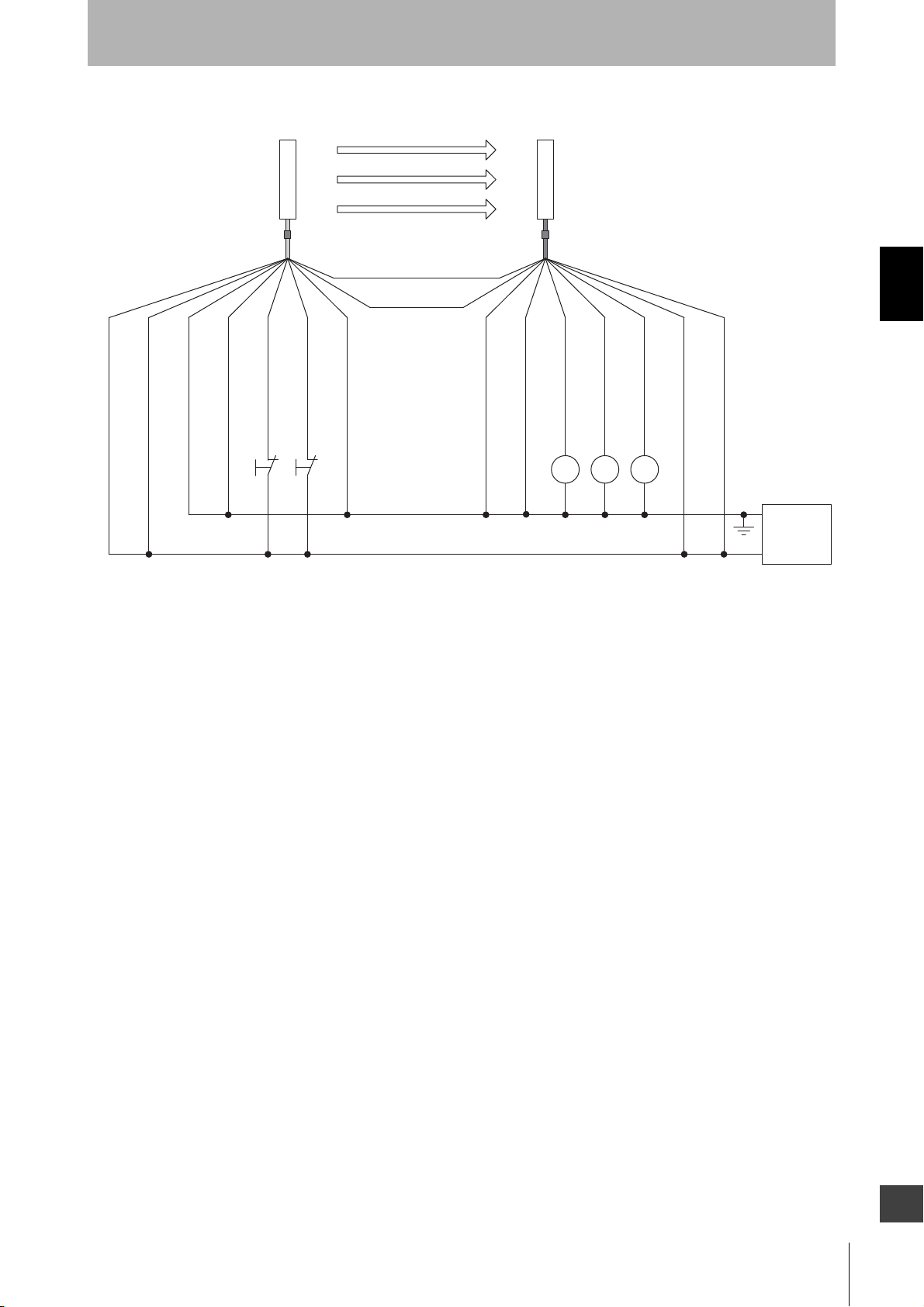
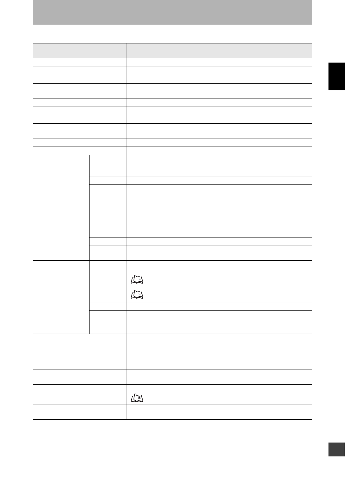
Wiring in use
System Configuration and Functions
Emitter
F39-JDA-L F39-JDA-D
(Gray) Communication line (+)
(Pink)
Communication line (-)
Shield
0 V (Blue)
Not Used (Red)
S1
S2
KM1, KM2
K1
*1. Use a switch for small loads (input specifications: 24 V, 1.0 mA max.).
*2. F3SJ operates even when K1 is not connected.
: External test switch (connect to 24 V if a switch is not required)
: Lockout reset switch (connect to 24 V if a switch is not required)
: Safety relay with force-guided contact (G7SA) or magnetic contactor
: Load or PLC, etc. (for monitoring)
Test input (Black)
Not Used (White)
S2
S1
*1 *1
24 V (Brown)
Reset input (Yellow)
24 V (Brown)
Receiver
Not Used (Red)
Auxiliary output (Yellow)
K1 KM1 KM2
*2
0 V (Blue)
Safety output 1 (Black)
Safety output 2 (White)
Shield
+24 VDC
Power
supply
0 V
Chapter2 Wiring Diagrams
F3SJ-B
User’s Manual
E
11
Page 26
System Configuration and Functions
Test input
Safety output
ON
OFF
ON
OFF
60 ms max. 140 ms max.
Description of Functions
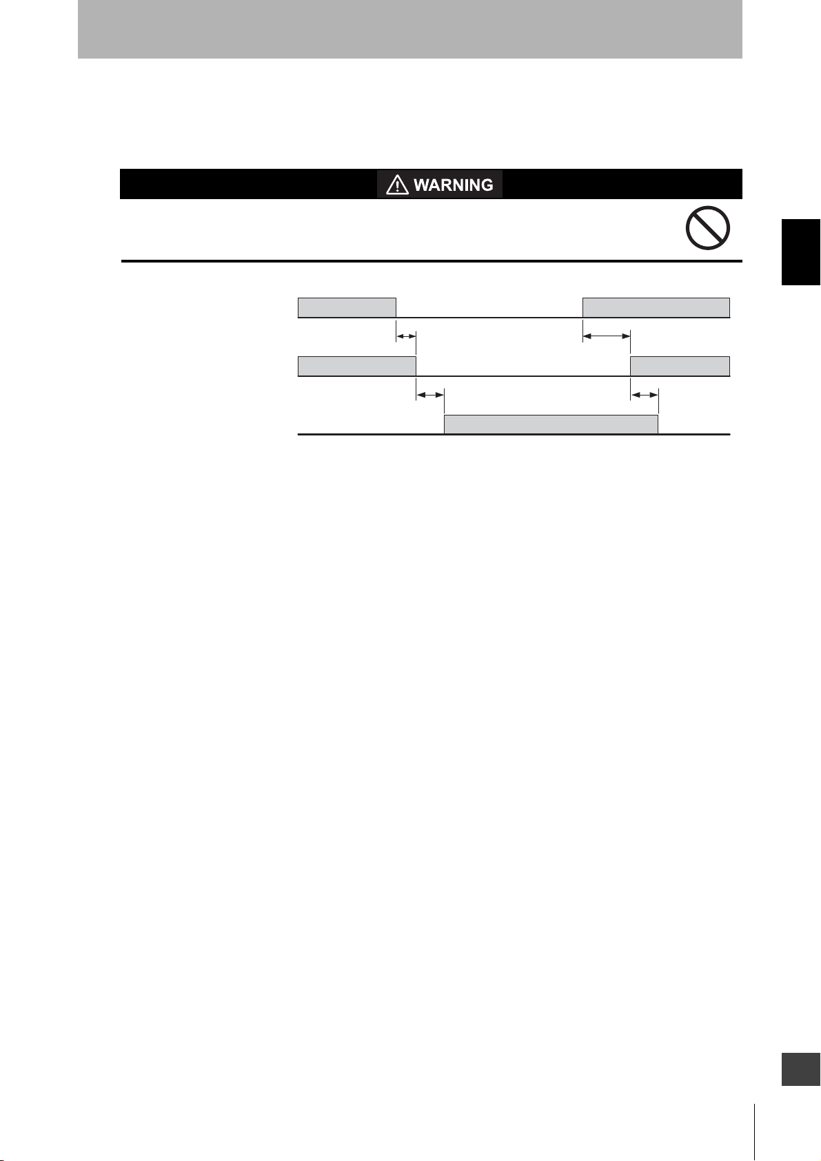
External Test Function
This function stops the emission using an external signal. It can be used to verify that a safety system
Chapter2 Description of Functions
should properly stop (safety output turns OFF) when F3SJ-B is interrupted.
To stop the emission, set open or apply voltage of 1/2 Vs to Vs to the test input line of the emitter.
12
F3SJ-B
User’s Manual
Page 27
System Configuration and Functions
Subsequently performs periodic test
Power supply
ON
OFF
Self test
ON
OFF
2 s max.
Self-test Function
The F3SJ-B performs the self-test when power is turned ON (within 2 seconds) to check for errors.
Also, it regularly performs the self-test (within a response time) while operating.
This function cannot be cancelled.
If an error is found in the self-test, the F3SJ-B enters lockout state, keeps the safety output in the OFF
state, and indicates the error at the same time.
Self-test details
The self-test detects the types of errors described below.
Emitter
• Failure of emitter element or circuit
• CPU failure
• Disconnected or short-circuited cable
Receiver
• Abnormal external power supply voltage
• Failure of internal power supply circuit
• Failure of receiver element or detection circuit
• CPU failure
• Memory failure
• Incidence of disturbance light
• Failure of safety output circuit
• Disconnected or short-circuited cable
Chapter2 Description of Functions
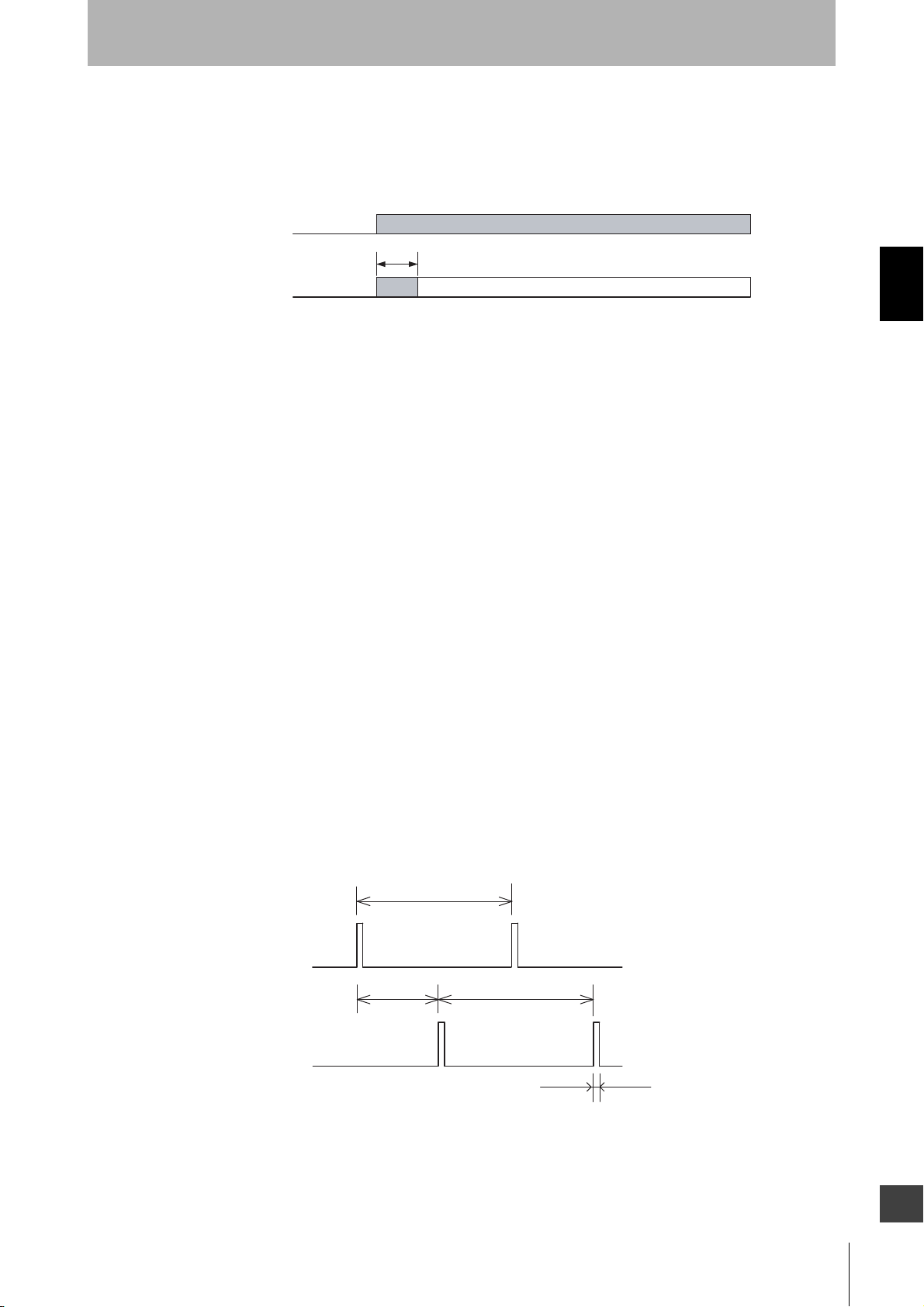
Waveform of safety outputs
When the F3SJ-B is receiving light, the safety outputs cyclically turn OFF as shown below to test the
output circuit. When this OFF signal is fed back, the output circuit is diagnosed as normal. If the output
signal does not include an OFF pulse signal due to short-circuit, etc, the receiver diagnoses a failure in
the output circuit or wiring, and it enters lockout state.
Approx. 15 to 30 ms
OFF
Safety output 1
ON
OFF
Safety output 2
ON
* An OFF pulse signal of safety output may extend to a maximum of about 100μs
due to the effect of the connected load (mostly capacitive load).
Approx.
7.5 to 15 ms
Approx. 15 to 30 ms
Approx. 40 μs max. *
F3SJ-B
User’s Manual
E
13
Page 28

System Configuration and Functions
Lockout Reset Function
When the cause of the lockout is removed, you can release the lockout by using either of the following
methods.
•Cycle the power back ON
•Reset input
Chapter2 Description of Functions
Open or apply 1/2 Vs to Vs to the reset input line (yellow) for 1 s or longer, and then apply a voltage of
0 V to 3 V again.
14
F3SJ-B
User’s Manual
Page 29
System Configuration and Functions
A
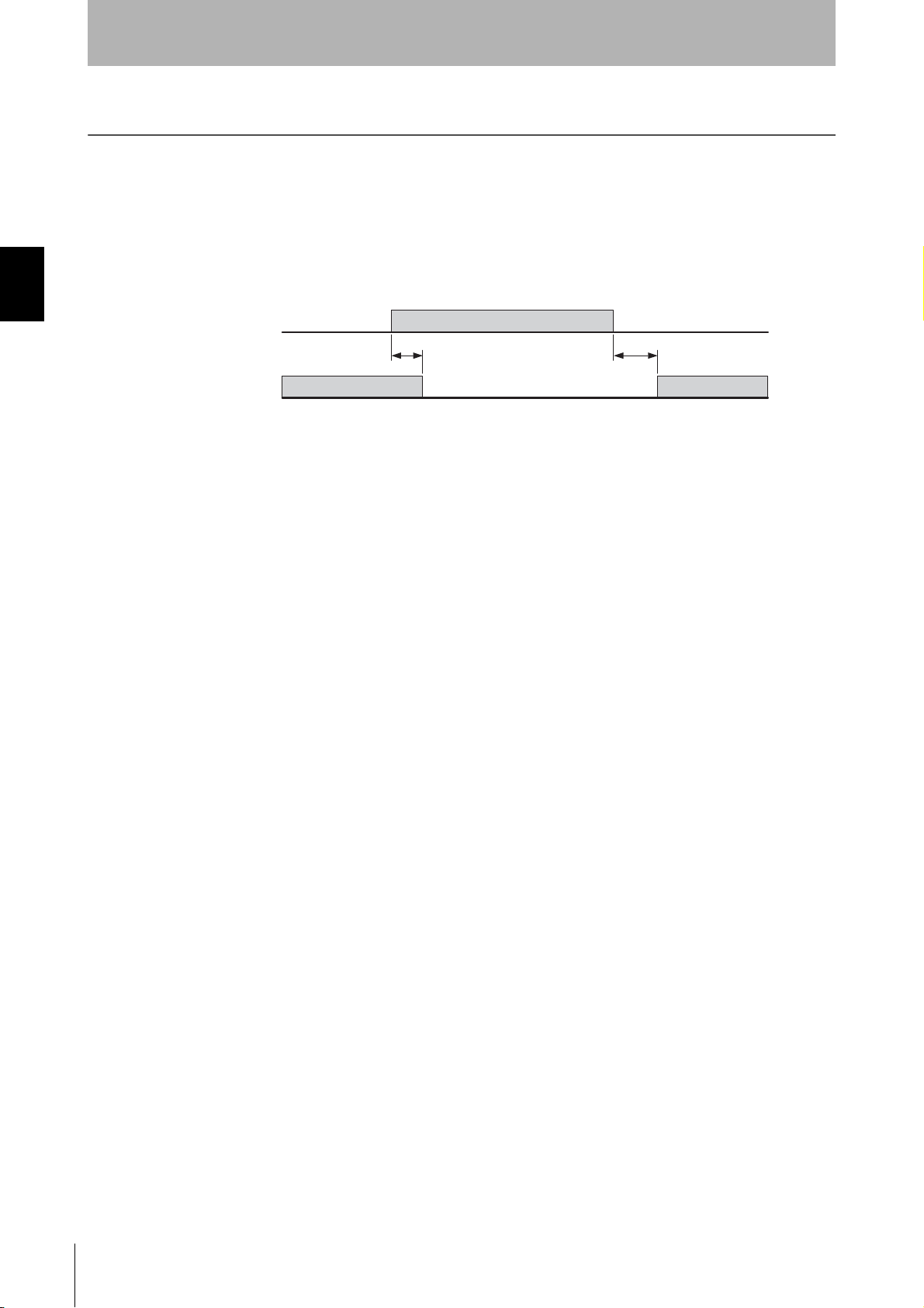
Auxiliary Output Function
The auxiliary output is used to monitor the status of the F3SJ-B. This output can be connected to a
device such as programmable controller.
Do not use the auxiliary output for safety applications.
Human body may not be detected when F3SJ-B fails, resulting in serious injury.
Unblocked
/Blocked
Safety output
uxiliary output
Unblocked
Blocked
ON
OFF
ON
OFF
15 ms
30 ms max. 30 ms max.
70 ms
Chapter2 Description of Functions
E
F3SJ-B
User’s Manual
15
Page 30

System Configuration and Functions
Chapter2 Description of Functions
16
F3SJ-B
User’s Manual
Page 31

Chapter3 Wiring/Installation
Installation Conditions 18
Detection Zone and Approach 18
Safety Distance 19
Distance from Reflective Surfaces 23
Mutual Interference Prevention 23
Series Connection 25
Connection Procedure 27
Dimensions 28
When Using Top/Bottom and Intermediate Brackets 29
When Using Intermediate Brackets Only (Free-Location Mounting) 33
When Using One-touch Brackets 37
When Using Replacement Brackets 42
When Using Contact Mount Brackets 45
When Using Spatter Protection Cover 48
Mounting 49
Chapter3 Wiring/Installation
Mounting Method 49
Number of Brackets Required 49
Mounting Procedure 50
Wiring 64
Wiring Precautions 64
Power Supply Unit 65
Wiring Method 66
F3SJ-B
User’s Manual
E
17
Page 32

Wiring/Installation
The hazardous zone of a machine can be reached
only by passing through the sensor's detection zone.
While working, a person is inside the sensor's
detection zone.
It is possible to reach the hazardous zone of a machine
without passing through the sensor's detection zone.
A person is between the sensor's detection zone
and the hazardous zone of a machine.
Installation Conditions
Detection Zone and Approach
Install a protective structure so that the hazardous part of a machine can only be reached
by passing through the sensor's detection zone. Install the sensors so that part of the
person is always present in the detection zone and no blind spot is generated when
working in a machine's hazardous zones.
Chapter3 Installation Conditions
If a person is able to step into the hazardous zone of a machine and remain behind the
F3SJ-B's detection zone, configure the system with an interlock function that prevents the
machine from being restarted. Failure to do so may result in serious injury.
Do not use this sensor for machines that cannot be stopped by electrical control. For
example, do not use it for a pressing machine that uses a full-rotation clutch. Otherwise, the
machine may not stop before a person reaches the hazardous part, resulting in serious injury.
To use the F3SJ-B in PSDI mode (Reinitiation of cyclic operation by the protective equipment),
you must configure an appropriate circuit between the F3SJ-B and the machine. For details about
PSDI, refer to OSHA 1910.217, IEC 61496-1, and other relevant standards and regulations.
Install the interlock reset switch in a location that provides a clear view of the entire
hazardous zone and where it cannot be activated from within the hazardous zone.
Do not use the F3SJ-B in environments where flammable or explosive gases are present.
Doing so may cause an explosion.
The F3SJ-B cannot protect a person from a projectile exiting the hazardous zone. Install
protective cover(s) or fence(s).
Make sure that the F3SJ-B is securely mounted and its cables and connectors are
properly secured.
Correct installation
Incorrect installation
F3SJ-B
18
User’s Manual
Page 33

Wiring/Installation
Hazard
Safety distance (S)
Safety Distance
The safety distance is the distance that must be set between the F3SJ-B and a machine's hazardous
part to stop the hazardous part before a person or object reaches it. The safety distance varies
according to the standards of each country and the individual specifications of each machine. Always
refer to relevant standards.
Make sure to secure the safety distance (S) between the F3SJ-B and the hazardous part.
Otherwise, the machine may not stop before a person reaches the hazardous part,
resulting in serious injury.
The response time of a machine is the time period from when the machine receives a stop signal to when the
machine's hazardous part stops. Measure the response time on the actual system. Also, periodically check to make
sure that the response time of the machine has not changed.
How to calculate the safety distance specified by International Standard ISO 13855
(European Standard EN ISO 13855) (Reference)
If a person approaches the detection zone of the F3SJ-B perpendicularly
S = K x T + C . . . Formula (1)
•S: Safety distance
•K: Approach speed to the detection zone
•T: Total response time of the machine and F3SJ-B
•C: Additional distance calculated by the detection capability
of the F3SJ-B
Chapter3 Installation Conditions
<System that has detection capability of 30 mm or less>
Use K = 2,000 mm/s and C = 8 x (d - 14 mm) in formula (1)
for the calculation.
S = 2,000 mm/s x (Tm + Ts) + 8 x (d - 14 mm)
•S = Safety distance (mm)
•Tm = Machine's response time (s)
•Ts = Response time of the F3SJ-B from ON to OFF (s)
•d = Detection capability of the F3SJ-B (mm)
[Calculation example]
When Tm = 0.05 s, Ts = 0.015 s, and d = 25 mm:
S = 2,000 mm/s x (0.05 s + 0.015 s) + 8 x (25 mm - 14 mm)
= 218 mm
If the result is less than 100 mm, use S = 100 mm.
If the result exceeds 500 mm, use the following formula where K = 1,600 mm/s.
S = 1,600 mm/s x (Tm + Ts) + 8 x (d - 14 mm) . . . Formula (2)
If the result of this formula (2) is less than 500 mm, use S = 500 mm.
F3SJ-B
User’s Manual
E
19
Page 34

Wiring/Installation
Possible circumventing by reaching over the detection zone
If access to the hazardous zone by reaching over the detection zone of vertically mounted F3SJ-E/B
cannot be excluded, the height and the safety distance, S, of the F3SJ-E/B shall be determined. S shall
be determined by comparison of the calculated values in Detection Zone Orthogonal to Direction of
Approach. The greater value resulting from this comparison shall be applied.
S=(K × T) + Cro . . . Formula (5)
•S: Safety distance
•K: Approach speed to the detection zone
Chapter3 Installation Conditions
•T: Total response time of the machine and F3SJ-E/B
•Cro: Approach distance based on the distance which
personnel can move towards the hazardous zone of a
machine by reaching over the detection zone. The distance
Hazard
b
a
Safety
distance (S)
is determined in the table below based on the height of the
hazardous zone, a, and the height of the upper edge of the
detection zone, b.
300 mm max.
Reference plane
Note:Lower edge of the detection zone above 300 mm in relation to the reference plane does not offer
sufficient protection against crawling below.
First, use K = 2,000 mm/s in formula (5) for the calculation. If the result of this calculation is less than
100 mm, use S = 100 mm.
If the result exceeds 500 mm, use K = 1,600 mm/s to recalculate it. If the result of the recalculation is
less than 500 mm, use S = 500 mm.
20
F3SJ-B
User’s Manual
Page 35

Wiring/Installation
Height of
hazardou
s zone, a
2600000000000000
2500 400 400 350 300 300 300 300 300 250 150 100 0
2400 550 550 550 500 450 450 400 400 300 250 100 0
2200 800 750 750 700 650 650 600 550 400 250 0 0
2000 950 950 850 850 800 750 700 550 400 0 0 0
1800110011009509508508007505500000
1600 1150 1150 1100 1000 900 850 750 450 0000
1400 1200 1200 1100 1000 900 850 650 00000
1200 1200 1200 1100 1000 850 800 000000
1000 1200 1150 1050 950 750 700 000000
800 1150 1050 950 800 500 450 000000
600 1050 950 750 550 00000000
4009007000000000000
20060000000000000
0 000000000000
900 1000 1100 1200 1300 1400 1600 1800 2000 2200 2400 2600
Height of upper edge of detection zone, b
Additional distance to hazardous zone, Cro
Note 1.Upper edge of the detection zone below 900 mm is not included since they do not offer
sufficient protection against circumventing or stepping over.
Note 2.When determining the values of this table, it shall not be interpolated. If the known values a, b
or Cro are between two values of this table, the greater safety distance shall be used.
Chapter3 Installation Conditions
[Calculation example]
•T: Tm + Ts (s)
•Tm: Machine's response time (s)
•Ts: Response time of the F3SJ-E/B from ON to OFF (s)
• a: Height of machine hazardous zone (mm)
• b: Height of upper edge of detection zone (mm)
When Tm = 0.05 s, Ts = 0.01 s, a = 1,400 mm, b = 1,500 m:
From the table above, Cro = 850 mm. Since b is between 1,400 mm and 1,600 mm, b = 1,400 mm
which has the greater Cro value, shall be used.
S = 2,000 mm/s × (0.05 s + 0.01 s) + 850 mm
= 970 mm
Since 970 mm is greater than 500 mm, use K = 1,600 mm/s and recalculate it.
S = 1,600 m/s × (0.05 s + 0.01 s) + 850 mm
= 946 mm
Compare S = 946 mm with the calculation in "If a person approaches the detection zone of the F3SJ
perpendicularly", and choose the larger value as the safety distance.
For the system with a detection capability of 40 mm max., the safety distance S is 946 mm since this
is larger than S = 120 mm calculated in the calculation example of "If a person approaches the
detection zone of the F3SJ perpendicularly".
For the system with a detection capability larger than 40 mm, the safety distance S is 946 mm since
this is the same value as S = 946 mm calculated in the calculation example of "If a person
approaches the detection zone of the F3SJ perpendicularly".
E
F3SJ-B
User’s Manual
21
Page 36

Wiring/Installation
Hazard
Safety distance (S)
H
If a person approaches the detection zone of the F3SJ-B horizontally
Use K = 1,600 mm/s and C = (1200 - 0.4 x H) in
formula (1) for calculation.
Note that C must not be less than 850 mm.
S = 1,600 mm/s x (Tm + Ts) + 1200 - 0.4 x H
•S = Safety distance (mm)
•Tm = Machine's response time (s)
•Ts = Response time of the F3SJ-B from ON to
Chapter3 Installation Conditions
OFF (s)
•H = Installation height of the F3SJ-B (mm)
Note that H must satisfy:
1000 >= H >= 15 (d - 50 mm)
Also, you must include a hazardous condition under which a person may go carelessly through under
a detection zone if it exceeds 300 mm (200 mm for other purpose than industrial use) into risk
assessment.
[Calculation example]
When Tm = 0.05 s, Ts = 0.015 s, d = 25 mm, and H = 500 mm:
S = 1,600 mm/s x (0.05 s + 0.015 s) + 1200 - 0.4 x 500 mm
= 1,104 mm
How to calculate the safety distance specified by American Standard ANSI B11.19
(reference)
If a person approaches the detection zone of the F3SJ-B perpendicularly, calculate the safety distance
as shown below.
S = K x (Ts + Tc + Tr + Tbm) + Dpf
•S: Safety distance
•K: Approach speed to the detection zone (the value recommended by OSHA standard is 1,600 mm/s)
Approach speed K is not specified in the ANSI B.11.19 standard. To determine the value of K to apply,
consider all factors, including the operator's physical ability.
•Ts = Machine's stopping time (s)
•Ts = Response time of the F3SJ-B from ON to OFF (s)
•Tc = Machine control circuit's maximum response time required to activate its brake (s)
•Tbm = Additional time (s)
If a machine has a brake monitor, "Tbm = Brake monitor setting time - (Ts + Tc)". If it has no brake
monitor, we recommend using 20% or more of (Ts + Tc) as additional time.
•Dpf = Additional distance
According to ANSI's formula, Dpf is calculated as shown below:
Dpf = 3.4 x (d - 7.0): Where d is the detection capability of the F3SJ-B (unit: mm)
22
[Calculation example]
When K = 1,600 mm/s, Ts + Tc = 0.06 s, brake monitor setting time = 0.1 s,
Tr = 0.015 s, and d = 25 mm:
Tbm = 0.1 - 0.06 = 0.04 s
Dpf = 3.4 x (25 - 7) = 61.2 mm
S = 1,600 mm/s x (0.06 s + 0.015 s + 0.04 s) + 61.2 mm = 245.2 mm
F3SJ-B
User’s Manual
Page 37

Wiring/Installation
L
D
Detection zone
D
Emitter
Receiver
Reflective ceiling
Reflective floor
L
D
Emitter
Receiver
5°
Reflective surface
5°
Emitter Receiver Emitter Receiver
Distance from Reflective Surfaces
Install the sensor system so that it is not affected by reflection from a glossy surface.
Failure to do so may hinder detection, resulting in serious injury.
Install the sensor system at distance D or further from highly reflective surfaces such as metallic walls,
floors, ceilings, or workpieces, as shown below.
Chapter3 Installation Conditions
Distance between an emitter and a
receiver (operating range L)
0.2 to 3 m 0.13 m
More than 3 m L/2 x tan5° = L x 0.044 (m)
Allowable installation distance D
Mutual Interference Prevention
Mutual interference is prevented in up to three sets, using interference light detection and cycle shift
algorithm.
If four or more sets of F3SJ-Bs are installed, arrange them so that mutual interference does not occur.
If two sets are installed near each other, reflection from the surface of the F3SJ-B may cause mutual
interference. When mutual interference occurs, the safety outputs are turned OFF in a moment or the
F3SJ-E/B enters lockout state.
Combining countermeasures 1 to 3 shown below is effective.
1. Install a physical barrier between two sets
E
F3SJ-B
User’s Manual
23
Page 38

Wiring/Installation
Aligned horizontally
Aligned fore and aft
Aligned vertically
Receiver Emitter Emitter Receiver
Emitter Receiver
Receiver Emitter
Receiver Emitter
Emitter Receiver
Emitter
Receiver
Emitter
Receiver
Emitter Receiver
Emitter Receiver
D
L
D
5°
5°
2. Alternate the direction of emission between two sets (alternation)
Chapter3 Installation Conditions
If two sets of F3SJ-Bs are installed near each other, reflection from the surfaces may cause mutual
interference.
3. Keep sufficient distance between the F3SJ-Bs so that mutual interference does not occur
Distance between emitter and
receiver (operating range L)
0.2 to 3 m 0.26 m
More than 3 m L x tan5° = L x 0.088 (m)
When using four or more sets, the installations shown below may cause mutual interference. When
mutual interference occurs, the safety outputs are turned OFF in a moment or the F3SJ-E/B enters
lockout state.
Emitter Receiver Emitter Receiver
Allowable installation distance D
Aligned horizontally
Aligned fore and aft
Emitter Receiver
Emitter Receiver
Aligned vertically
Emitter
Emitter
Receiver
Receiver
24
F3SJ-B
User’s Manual
Page 39

Wiring/Installation
Secondary
sensor 2 (3CH)
Secondary
sensor 1 (2CH)
Primary
sensor (1CH)
Series Connection
Up to three sets of F3SJ-Bs can be series-connected. Series connection allows them to be used as a safety
light curtain, requiring only one set to be wired to a controller and preventing mutual interference.
If any one set of series-connected F3SJ-B is blocked, both of the safety outputs turn OFF. The indication LED
for each F3SJ-B turns ON separately.
• Number of connections: Up to three sets
• Total number of beams: Up to 192 beams
• Connection cable length between two F3SJ-Bs in series connection: 7 m max.
Ex.: Configuring an U-shaped detection zone
Chapter3 Series Connection
The terms used in this document to describe each F3SJ-B in a series connection are shown below.
F3SJ-B
User’s Manual
E
25
Page 40

Wiring/Installation
Properly connect an emitter to another emitter, and a receiver to another receiver, as shown below.
Chapter3 Series Connection
Secondary
sensor 1
(Emitter)
Primary
sensor
(Emitter)
Do not series-connect an emitter and
receiver. They will enter lockout state.
Do not face different models of emitters
and receivers toward each other. They
will enter lockout state or will be unable
to detect objects.
Secondary
sensor 1
(Receiver)
Primary
sensor
(Receiver)
Secondary
sensor 1
(Emitter )
Primary
sensor
(Receiver)
Secondary
sensor 1
(Receiver)
Primary
sensor
(Emitter)
Primary
sensor 1
(Emitter)
Secondary
sensor
(Emitter)
Secondary
sensor 1
(Receiver)
Primary
sensor
(Receiver)
If caps and series connection cables for extension are not connected properly, the F3SJ-B enters lockout (when power is
turned ON).
26
F3SJ-B
User’s Manual
Page 41

Wiring/Installation
1. 1.
1. 1.
2. 2.
2. 2.
3. 3.
3. 3.
Cap
Cap
F39-JBR2W
F39-JD
□B
F39-JBR2W
F39-JD
□B
Receiver’s
power supply
cable end
Emitter’s
power supply
cable end
Emitter’s
power supply
cable end
Receiver’s
power supply
cable end
<Secondary sensor>
<Primary sensor>
Connection Procedure
1. Remove the caps from the primary sensor. Loosen the screw (M3 cross-shaped) to remove the cap.
2. Use the F39-JBR2W series connection cable for extension to connect them.
3. When changing the connection distance between the F3SJ-Bs, connect a F39-JDB double-ended
connector cable (sold separately).
Chapter3 Series Connection
- When attaching a cable or cap, securely fasten the screws (M3 cross-shaped (2 for each), recommended torque:
- Attaching/detaching of a cap or a series-connection cable may cause misalignment of rubber grommet in a
0.54 N•m).
Failure to do so may cause the cable/cap to come loose, leading to deterioration of the protective functions.
connector assembly.
Press the grommet to the bottom of the connector and attach the connector F3SJ-B again.
F3SJ-B
User’s Manual
E
27
Page 42

Chapter3 Dimensions
M12 IP67 connector (plug)
dia.6
300
42.8
dia.15
[Unit: mm]
Wiring/Installation
Dimensions
28
F3SJ-B
User’s Manual
Page 43

Wiring/Installation
P (beam gap)
[ Unit : mm ]
13.4
22.5
34.5
B
A
5.5
30
19
6.5
dia.9
7.5
18.3
7
22
30
30
D
53
42
C (Protective height)
30
13
2
43
6.5
45
<M5 screw fixed> <M8 screw fixed>
Top/Bottom Bracket
(F39-LJB1)
Top/Bottom Bracket
(F39-LJB1)
Intermediate Bracket
(F39-LJB2)
2
E
19
B
B
E
C
C
E
42
42
5.9 5.9
22 22
4-M5
2-M8
2-M5 2-M5
M3 x 6 screw
M3 x 6 screw
Dimensions A to E and P
Dimensions E
* Value E must be 700 mm or less when not using value E obtained from the calculation above.
AC+69
B C+42.2
C 4-digit number of the type name (protective height)
DC-45
E Depends on the protective height. See the table below.
P20
Protective height Number of Intermediate Brackets Dimensions E
0185 to 1105 0 1185 to 1345 1 C/2 max.
1425 to 2065 2 C/3 max.
When Using Top/Bottom and Intermediate Brackets
Backside mounting
Chapter3 Dimensions
Bracket mounting procedure (Mounting) p.49
- If the protective height is 1105 mm or more, use Intermediate Brackets of specified quantities and locations
according to the dimensions. If the brackets described above are not used, ratings and performance cannot be met.
- When you use a sensor in a situation where the sensor is under a load, add an Intermediate Bracket.
E
F3SJ-B
User’s Manual
29
Page 44

Wiring/Installation
Dimensions A to E
Dimensions E
* Value E must be 700 mm or less when not using value E obtained from the calculation above.
AC+69
BC+42.2
C 4-digit number of the type name (protective height)
DC-45
E Depends on the protective height. See the table below.
Protective height Number of Intermediate Brackets Dimensions E
0185 to 1105 0 1185 to 1345 1 C/2 max.
1425 to 2065 2 C/3 max.
Side mounting
Top/Bottom Bracket
(F39-LJB1)
dia.9
18.3
30
30
19
6.5
7.5
M3 x 6 screw
46
30
34.5
4-M5
19
2-M8
Chapter3 Dimensions
Intermediate Bracket
(F39-LJB2)
Top/Bottom Bracket
(F39-LJB1)
7
22 22
B
B
53
42
5.5
34
42
12
A
E
13.4
D
C (Protective height)
22.5
M3 x 6 screw
42
2-M5 2-M5
16
C
42
E
B
C
E
5.9 5.9
<M5 screw fixed> <M8 screw fixed>
45
[ Unit : mm ]
F3SJ-B
30
User’s Manual
Bracket mounting procedure (Mounting) p.49
- If the protective height is more than 1105 mm, use Intermediate Brackets of specified quantities and locations
according to the dimensions. If the brackets described above are not used, ratings and performance cannot be met.
- When you use a sensor in a situation where the sensor is under a load, add an Intermediate Bracket.
Page 45

Dimensions of Top/Bottom Brackets
Wiring/Installation
34.5
18.3
4.3
19
16
30
dia.9
7.5
6.5
2
Dimensions of Intermediate Brackets (backside mounting)
80
30
Chapter3 Dimensions
43
Material : Stainless
[ Unit : mm ]
45
15
7
5.5
42
53
8
(35.7)
(31.5)
Material : Zinc die-cast
[ Unit : mm ]
8
(13)
E
F3SJ-B
User’s Manual
31
Page 46

Chapter3 Dimensions
8
(46)
(16)
8
53
42
5.5
26
80
30
15
7
45
[ Unit : mm ]
Material : Zinc die-cast
Wiring/Installation
Dimensions of Intermediate Brackets (side mounting)
32
F3SJ-B
User’s Manual
Page 47

Wiring/Installation
[ Unit : mm ]
15
22
7
F
42
5.5
275 max 275 max
C (Protective height)
43
30 30
Intermediate Bracket
(F39-LJB2)
Intermediate Bracket
(F39-LJB2)
22
42
4-M5
42
F
C
Dimensions C and F
Dimensions F
C 4-digit number of the type name (protective height)
F Depends on the protective height. See the table below.
Protective height Number of Intermediate Brackets Dimensions F
0185 to 0225 1 0305 to 1105 2 555 mm max.
1185 to 1585 3 555 mm max.
1665 to 2065 4 555 mm max.
When Using Intermediate Brackets Only (Free-Location Mounting)
Backside mounting
Chapter3 Dimensions
Bracket mounting procedure (Mounting) p.49
The alignment range of the Intermediate Bracket must be ±30°.
E
F3SJ-B
User’s Manual
33
Page 48

Chapter3 Dimensions
22
42
C
C
C
C
C/2
C/2
C/2
FF
FF
C
FFF
C/2
22
42 4242
C
FFF
22
42 4242 42
2-M5
6-M5
8-M5
275 max 275 max
275 max 275 max
275 max 275 max
• Mounting with one Intermediate Bracket • Mounting with three Intermediate Brackets • Mounting with four Intermediate Brackets
[Unit: mm]
Wiring/Installation
34
F3SJ-B
User’s Manual
Page 49

Side mounting
[ Unit : mm ]
42
275 max 275 max
275 max 275 max
5.5
7
3
F
C (Protective height)
C (Protective height)
45
37
33
16
30
42 42
F
Intermediate Bracket
(F39-LJB2)
Intermediate Bracket
(F39-LJB2)
Dimensions C and F
Dimensions F
C 4-digit number of the type name (protective height)
F Depends on the protective height. See the table below.
Protective height Number of Intermediate Brackets Dimensions F
0185 to 0225 1 0305 to 1105 2 555 mm max.
1185 to 1585 3 555 mm max.
1665 to 2065 4 555 mm max.
Wiring/Installation
Chapter3 Dimensions
Bracket mounting procedure (Mounting) p.49
The alignment range of the Intermediate Bracket must be ±30°.
E
F3SJ-B
User’s Manual
35
Page 50

Chapter3 Dimensions
42
C
C
C
C
C/2
C/2
C/2
275 max 275 max
275 max 275 max
275 max 275 max
275 max 275 max
FF
FF
C
FFF
C/2
42 4242
C
FFF
42 4242 42
2-M5
6-M5
8-M5
• Mounting with one Intermediate Bracket • Mounting with three Intermediate Brackets • Mounting with four Intermediate Brackets
[Unit: mm]
Wiring/Installation
36
F3SJ-B
User’s Manual
Page 51

When Using One-touch Brackets
43
30
3030
F
C (Protective height)
15
275 max 275 max
[ Unit : mm ]
<M6 screw fixed> <M8 screw fixed>
C
C
32.1 32.1
2-M6
F
32.1 32.1
2-M8
F
One-touch Bracket
(F39-LJB3-M6 or
F39-LJB3-M8)
One-touch Bracket
(F39-LJB3-M6 or
F39-LJB3-M8)
Dimensions C and F
Dimensions F
C 4-digit number of the type name (protective height)
F Depends on the protective height. See the table below.
Protective height Number of Intermediate Brackets Dimensions F
0185 to 1105 2 555 mm max.
1185 to 1585 3 555 mm max.
1665 to 2065 4 555 mm max.
Backside mounting
Wiring/Installation
Chapter3 Dimensions
Bracket mounting procedure (Mounting) p.49
The alignment range of the One-touch Bracket must be ±30°.
F3SJ-B
User’s Manual
E
37
Page 52

Chapter3 Dimensions
C
FF
FF
275 max275 max
275 max 32.1
3-M6
32.1 32.1
275 max
C/2
C/2
C
C
FF F 275 max275 max
FF
275 max
32.1
3-M8
32.1 32.1
275 max
C/2
C
FF F
275 max
32.1
4-M6
32.1 32.1
275 max
C
32.1
FF F
275 max
32.1
4-M8
32.1 32.1
275 max
C
32.1
• Mounting with three One-touch Brackets • Mounting with four One-touch Brackets
<M6 screw fixed> <M8 screw fixed> <M6 screw fixed> <M8 screw fixed>
[Unit: mm]
Wiring/Installation
38
F3SJ-B
User’s Manual
Page 53

Side mounting
[ Unit : mm ]
16
30
45
33
3
275 max 275 max
F
C (Protective height)
12
<M6 screw fixed> <M8 screw fixed>
C
C
32.1 32.1
2-M6
F
32.1 32.1
2-M8
F
One-touch Bracket
(F39-LJB3-M6 or
F39-LJB3-M8)
One-touch Bracket
(F39-LJB3-M6 or
F39-LJB3-M8)
Dimensions C and F
Dimensions F
C 4-digit number of the type name (protective height)
F Depends on the protective height. See the table below.
Protective height Number of Intermediate Brackets Dimensions F
0185 to 1105 2 555 mm max.
1185 to 1585 3 555 mm max.
1665 to 2065 4 555 mm max.
Wiring/Installation
Chapter3 Dimensions
Bracket mounting procedure (Mounting) p.49
The alignment range of the One-touch Bracket must be ±30°.
E
F3SJ-B
User’s Manual
39
Page 54

Wiring/Installation
• Mounting with three One-touch Brackets • Mounting with four One-touch Brackets
Chapter3 Dimensions
275 max275 max
C/2
FF
C
32.1
3-M6
275 max 275 max
C/2
C
32.1
3-M8
FF
32.1 32.1
275 max 275 max
C/2
C
FF
32.1 32.1
C
275 max275 max
FFF
4-M6
32.1
C
32.1
FF F
32.1 32.1
275 max 275 max
4-M8
32.1
C
32.1
FF F
32.1 32.1
275 max 275 max
<M6 screw fixed> <M8 screw fixed> <M6 screw fixed> <M8 screw fixed>
[Unit: mm]
40
F3SJ-B
User’s Manual
Page 55

Wiring/Installation
22
1.5
8
dia.6.2
dia.13
Material : Stainless
22
1.5
8
dia.8.2
dia.17
Material : Stainless
80
(32.1) (32.1)
45
15
30
dia.22
dia.22
[ Unit : mm ]
30
53
8
(13)
(31.5)
(35.7)
Material : Zinc die-cast
45
15
30
8
(46)
(16)
Material : Zinc die-cast
80
(32.1) (32.1)
dia.22
dia.22
[ Unit : mm ]
26
53
Dimensions of One-touch M6 Bracket Dimensions of One-touch M8 Bracket
Dimensions of Intermediate Bracket + One-touch Bracket (backside mounting)
Dimensions of Intermediate Bracket + One-touch Bracket (side mounting)
Chapter3 Dimensions
F3SJ-B
User’s Manual
E
41
Page 56

Chapter3 Dimensions
19
4-M5
B
Replacement Bracket
(F39-LJB4)
Replacement Bracket
(F39-LJB4)
43
13
30
19
6.5
62
30
B
C (Protective height)
A
79.5
36.5
[ Unit : mm ]
M3 x 6 screw
M3 x 6 screw
Dimensions A to C
A C+159
BC+86
C 4-digit number of the type name (protective height)
Wiring/Installation
When Using Replacement Brackets
Backside mounting
Bracket mounting procedure (Mounting) p.49
If the protective height is more than 1105 mm, use Intermediate Brackets of the quantities and locations according to
the dimensions described on page 29 "When Using Top/Bottom and Intermediate Brackets". If the brackets described
above are not used, ratings and performance cannot be met.
42
F3SJ-B
User’s Manual
Page 57

Side mounting
[ Unit : mm ]
36.5
79.5
A
C (Protective height)
B
46
2
30
30
19
6.5
30
62
19
B
4-M5
Replacement Bracket
(F39-LJB4)
Replacement Bracket
(F39-LJB4)
M3 x 6 screw
M3 x 6 screw
Dimensions A to E and P
A C+159
BC+86
C 4-digit number of the type name (protective height)
Wiring/Installation
Chapter3 Dimensions
Bracket mounting procedure (Mounting) p.49
If the protective height is more than 1105 mm, use Intermediate Brackets of the quantities and locations according to
the dimensions described on page 29 "When Using Top/Bottom and Intermediate Brackets". If the brackets described
above are not used, ratings and performance cannot be met.
F3SJ-B
User’s Manual
E
43
Page 58

Chapter3 Dimensions
Material: Stainless
[ Unit : mm ]
16
30
2
43
6.5
19
5.5
62
79.5
Wiring/Installation
Dimensions of replacement bracket
44
F3SJ-B
User’s Manual
Page 59

When Using Contact Mount Brackets
Dimensions A to D
AC+69
B C+47.5
C 4-digit number in the Model name (protective height)
DC-45
Backside mounting
Contact Mount
Bracket
(F39-LJB5)
32
2
2
M3 x 6 screw
6.5
7
30
19
Dia. 9
4-M5
3.25
19
Wiring/Installation
2-M8
3.25
Contact Mount
Bracket
(F39-LJB5)
30
D
C(Protective height)
22.5
34.5
M3 x 6 screw
30
30
P(beam gap)
A
B
10.75
B
C
<M5 screw fixed> <M8 screw fixed>
C
3.25
Chapter3 Dimensions
B
- The protective height of the F3SJ-E/B series that supports the contact mount bracket is limited.
Protective height allowed for mounting: 185 mm to 1,105 mm.
- Brackets of other models such as F39-LJB1 cannot be used simultaneously.
F3SJ-B
User’s Manual
E
45
Page 60

Chapter3 Dimensions
33
D
34.5
30
35
5
22.5
12
10.75 B
7
3.25
30
6.5
A
30
Dia. 9
19
C
B
3.25
2-M8
3.25
C
B
19
4-M5
<M5 screw fixed> <M8 screw fixed>
Contact Mount
Bracket
(F39-LJB5)
Contact Mount
Bracket
(F39-LJB5)
M3 x 6
screw
M3 x 6 screw
Dimensions A to D
A C+69
B C+47.5
C 4-digit number in the Model name (protective height)
D C - 45
Wiring/Installation
Side mounting
46
F3SJ-B
User’s Manual
- The protective height of the F3SJ-E/B series that supports the contact mount bracket is limited.
Protective height allowed for mounting: 185 mm to 1,105 mm.
- Brackets of other models such as F39-LJB1 cannot be used simultaneously.
Page 61

Dimensions of contact mount bracket
16
30
32
2
13.54
7.5
34.5
19
6.5
dia. 9
Material: Stainless
(Unit: mm)
Wiring/Installation
Chapter3 Dimensions
E
F3SJ-B
User’s Manual
47
Page 62

Chapter3 Dimensions
L = □□□□ - 21mm
Material: PC (Protection cover)
L
L
10
3232
10
[ Unit : mm ]
Wiring/Installation
When Using Spatter Protection Cover
Dimensions of Spatter Protection Cover F39-HB
Assembly Dimensions
32
35.5
[ Unit : mm ]
48
F3SJ-B
User’s Manual
Page 63

Mounting
Mounting Method
Mounting methods include use of Top/Bottom Brackets, Top/Bottom Brackets + Intermediate Brackets,
Intermediate Brackets only (Free-Location Mounting) and use of One-touch Brackets. Any of these
mounting methods allows the user to use the same bracket for the backside mounting and side
mounting.
Wiring/Installation
Number of Brackets Required
The numbers of brackets required according to the protective heights of the sensor are as follows:
•When Using Top/Bottom Brackets Only --> p.50
•When Using Top/Bottom + Intermediate Brackets --> p.52
Protective height
0185 to 1105 2 0
1185 to 1345 2 1
1425 to 2065 2 2
Number of Top/
Bottom Brackets
• When Using Intermediate Brackets Only --> p.56
Protective height
0185 to 0225 1
0305 to 1105 2
1185 to 1585 3
1665 to 2065 4
Number of
Intermediate Brackets
• When Using One-touch Bracket --> p.59
Protective height
0185 to 1105 2
1185 to 1585 3
1665 to 2065 4
Number of One-touch
Brackets
Number of
Intermediate Brackets
Chapter3 Mounting
F3SJ-B
User’s Manual
E
49
Page 64

Chapter3 Mounting
Tighten
securely
Hexagon socket head
cap screws (M3 x 6)
Tighten lightly
Top/Bottom
Mounting Bracket
Side mounting Backside mounting
Anti-rotation hexagon
socket head cap screw
(M3 x 8)
Anti-rotation hexagon
socket head cap screw
(M3 x 8)
Loosen Loosen
Tighten lightly
Figure 1
Tighten
securely
Side mounting
Backside mounting
Tighten
securely
Figure 2
Wiring/Installation
Mounting Procedure
Using Top/Bottom Bracket only
1. Attach Top/Bottom Brackets and tighten them using the included hexagon socket head cap screws (M3
x 6). Tighten the hexagon socket head cap screws (M3 x 6) with the torque at 0.54 N•m
(recommended). (Figure 1)
Loosen the hexagon socket head cap screws (M3 x 6), prepare brackets for backside or side
mountings, and then lightly tighten them with the hexagon socket head cap screws (M3 x 6).
2. Adjust the Top/Bottom Brackets to the mounting position of the wall surface and then tighten them with
F3SJ-B
50
User’s Manual
screws. (Figure 2)
Screws to mount the brackets to the wall are not included.
Page 65

Wiring/Installation
Figure 3 Figure 4
Enlarged view
Side mounting
Backside mounting
Tighten
securely
Tighten
securely
Tighten
securely
Hexagon socket head
cap screw (M3 x 8)
Figure 5
3. Turn ON the sensor to perform beam alignment.
Move the emitter from side to side (Figure 3) to align it to a center position where the stable-state
indicator (STB) is turned ON while checking the top beam state and bottom beam state with the topbeam-state indicator (TOP) and bottom-beam-state indicator (BTM). (Figure 4)
Next, move the receiver from side to side (Figure 3) to align it to a center position where the stablestate indicator (STB) is turned ON. (Figure 4)
Emitter Receiver
TOP indicator
(Blue)
STB indicator
(Green)
BTM indicator
(Blue)
Chapter3 Mounting
EMITTER
- Confirm that there is no interrupting object in the detection zone before adjusting beams.
- If the stable-state indicator (STB) does not turn ON despite performing alignment, check if the mounting surfaces of
the emitter/receiver are parallel, and if the mounting height of the emitter/receiver is appropriate. Using optional
Laser Alignment Kit (F39-PTJ) makes alignment easier.
RECEIVER
4. Tighten the lightly tightened hexagon socket head cap screws (M3 x 6) of the Top/Bottom Brackets.
(Figure 5)
Tighten the hexagon socket head cap screws (M3 x 6) with the torque at 0.54 N•m (recommended).
Tightening screws with a torque that considerably exceeds the recommended torque may cause failure.
Mounting is complete.
F3SJ-B
User’s Manual
E
51
Page 66

Chapter3 Mounting
Intermediate Bracket (1)
Hexagon socket head
cap screw (M3 x 12)
Hexagon socket head
cap screw (M3 x 18)
Loosen
Intermediate Bracket (2)
Intermediate Bracket (3)
Loosen
Backside mounting
Figure 6
Loosen
Hexagon socket head
cap screw (M3 x 18)
Intermediate Bracket (1)
Intermediate Bracket (1)
Intermediate Bracket (2)
Intermediate
Bracket (2)
Intermediate Bracket (3)
Intermediate
Bracket (1)
Intermediate Bracket (2)
Attach the intermediate
mounting bracket (2) to (3).
Turn the intermediate mounting bracket (2) so that
the intermediate bracket (1) should be the bottom.
Detach the intermediate
mounting bracket (2) from (3).
Intermediate Bracket (3)
Intermediate Bracket (3)
Loosen
Side mounting
Hexagon socket head
cap screw (M3 x 12)
Figure 7
Figure 8
Wiring/Installation
When Using Top/Bottom + Intermediate Brackets
1. Loosen the hexagon socket head cap screw (M3 x 18) of the intermediate bracket (3) and the hexagon
socket head cap screw (M3 x 12) of the intermediate bracket (1) to be able to attach the bracket to the
sensor case. (Figure 6 and 7)
The intermediate bracket has been assembled for backside mounting.
To use it for side mounting, remove the intermediate bracket (2) from the intermediate bracket (3) and
change the direction of the bracket as shown in Fig.7.
2. Mount the Intermediate Bracket to the case, and then lightly tighten the hexagon socket head cap
52
F3SJ-B
User’s Manual
screws (M3 x 12) of Intermediate Bracket (1). (Figure 8)
Side mountingBackside mounting
Intermediate Bracket (1) Intermediate Bracket (1)
Tighten lightly
Sensor is secured by
Intermediate Brackets.
Optical surface
Intermediate
Bracket (2)
Intermediate
Bracket (3)
Optical surface
Intermediate Bracket (2)
Sensor is secured by
Intermediate Brackets.
Tighten lightly
Intermediate
Bracket (3)
Page 67

Wiring/Installation
Tighten
securely
Hexagon socket head
cap screws (M3 x 6)
Tighten lightly
Top/Bottom
Mounting Bracket
Side mounting Backside mounting
Anti-rotation hexagon
socket head cap screw
(M3 x 8)
Anti-rotation hexagon
socket head cap screw
(M3 x 8)
Loosen Loosen
Tighten lightly
Figure 9
Figure 10
3. Attach a Top/Bottom Bracket and lightly tighten it using the included hexagon socket head cap screws
(M3x6).
Tighten the hexagon socket head cap screws (M3 x 6) with the torque at 0.54 N•m (recommended).
Loosen the hexagon socket head cap screws (M3 x 6), prepare brackets for backside or side
mountings, and then lightly tighten them with the hexagon socket head cap screws (M3 x 6). (Figure 9)
Chapter3 Mounting
4. Position the Top/Bottom Brackets and the Intermediate Brackets to the mounting location on the wall
and tighten the hexagon socket head cap screws (M3 x 12). (Figure 10)
Tighten the hexagon socket head cap screws (M3 x 12) with the torque at 0.54 N•m (recommended).
Tighten
securely
Tighten
securely
Adjust to the
mounting position
Side mountingBackside mounting
F3SJ-B
User’s Manual
E
53
Page 68

Chapter3 Mounting
Tighten the screws to secure
the Intermediate Bracket (3)
and the wall.
Tighten the screws to secure
the Top/Bottom Brackets
and the wall.
Figure 11
Emitter Receiver
TOP indicator
(Blue)
STB indicator
(Green)
BTM indicator
(Blue)
RECEIVER
EMITTER
Figure 12 Figure 13
Wiring/Installation
5.
Tighten the screws to mount to the wall by the order of Top/Bottom and Intermediate Brackets. (Figure 11)
Screws to mount the brackets to the wall are not included.
6. Turn ON the sensor to perform beam alignment.
Move the emitter from side to side (
indicator (STB) is turned ON while checking the top beam state and bottom beam state with the topbeam-state indicator (TOP) and bottom-beam-state indicator (BTM). (
Next, move the receiver from side to side to align it to a center position where the stable-state indicator
(STB) is turned ON. (
Figure 13
)
Figure 12
) to align it to a center position where the stable-state
Figure 13
)
54
- Confirm that there is no interrupting object in the detection zone before adjusting beams.
- If the stable-state indicator (STB) does not turn ON despite performing alignment, check if the mounting surfaces of
the emitter/receiver are parallel, and if the mounting height of the emitter/receiver is appropriate. Using optional
Laser Alignment Kit (F39-PTJ) makes alignment easier.
F3SJ-B
User’s Manual
Page 69

Wiring/Installation
Enlarged view
Tighten
securely
Hexagon socket head
cap screw (M3 x 8)
Side mounting
Backside mounting
Tighten
securely
Tighten
securely
Enlarged view
Side mounting
Backside mounting
Tighten
securely
Tighten
securely
Hexagon socket
head cap screw
(M3 x 18)
Figure 14
7. Tighten the lightly tightened hexagon socket head cap screws (M3 x 6, M3 x 18) to prevent rotation of
the Top/Bottom Brackets and Intermediate Bracket. (Figure 14)
Tighten the hexagon socket head cap screws (M3 x 6, M3 x 18) with the torque at 0.54 N•m
(recommended).
Chapter3 Mounting
Tightening screws with a torque that considerably exceeds the recommended torque may cause failure.
Mounting is complete.
F3SJ-B
User’s Manual
E
55
Page 70

Chapter3 Mounting
Intermediate Bracket (1)
Hexagon socket head
cap screw (M3 x 12)
Hexagon socket head
cap screw (M3 x 18)
Loosen
Intermediate Bracket (2)
Intermediate Bracket (3)
Loosen
Backside mounting
Figure 15
Figure 16
Figure 17
Wiring/Installation
When using Intermediate Bracket (Free-Location Mounting)
1. Loosen the hexagon socket head cap screw (M3 x 18) of the intermediate bracket (3) and the hexagon
socket head cap screw (M3 x 12) of the intermediate bracket (1) to be able to attach the bracket to the
sensor case. (Figure 15 and 16)
The intermediate bracket has been assembled for backside mounting.
To use it for side mounting, remove the intermediate bracket (2) from the intermediate bracket (3) and
change the direction of the bracket as shown in Fig.16.
Side mounting
Detach the intermediate
mounting bracket (2) from (3).
Hexagon socket head
cap screw (M3 x 12)
Loosen
Hexagon socket head
cap screw (M3 x 18)
Intermediate
Bracket (2)
Intermediate Bracket (1)
Intermediate Bracket (2)
Intermediate Bracket (3)
Turn the intermediate mounting bracket (2) so that
the intermediate bracket (1) should be the bottom.
Intermediate Bracket (1)
Intermediate Bracket (2)
Intermediate Bracket (3)
Attach the intermediate
mounting bracket (2) to (3).
Intermediate
Bracket (1)
Intermediate Bracket (3)
Loosen
2. Mount the Intermediate Bracket to the case, and lightly tighten the hexagon socket head cap screws
(M3 x 12) of Intermediate Bracket (1). (Figure 17)
Side mountingBackside mounting
Intermediate Bracket (1) Intermediate Bracket (1)
Tighten lightly
Optical surface
Optical surface
Tighten lightly
56
F3SJ-B
User’s Manual
Sensor is secured by
Intermediate Brackets.
Intermediate
Bracket (2)
Intermediate
Bracket (3)
Intermediate Bracket (2)
Intermediate
Bracket (3)
Sensor is secured by
Intermediate Brackets.
Page 71

3. Slide the Intermediate Brackets to the mounting position of the wall. (Figure 18)
Figure 18
Side mountingBackside mounting
Tighten the screws to secure
the Intermediate
Brackets and the wall.
Tighten the screws to secure
the Intermediate
Brackets and the wall.
Figure 19
Figure 20
Side mountingBackside mounting
Adjust to the
mounting position
Screws to mount the brackets to the wall are not included.
4. Tighten the screws that fix the Intermediate Bracket and the wall. (Figure 19)
Wiring/Installation
Chapter3 Mounting
5. Tighten the hexagon socket head cap screw (M3 x 12) of Intermediate Bracket (1) with the tightening
torque at 0.54 N•m (recommended). (Figure 20)
Tighten
securely
Hexagon socket head
cap screw (M3 x 12)
Tightening screws with a torque that considerably exceeds the recommended torque may cause failure.
F3SJ-B
User’s Manual
E
57
Page 72

Chapter3 Mounting
Emitter
Receiver
TOP indicator
(Blue)
STB indicator
(Green)
BTM indicator
(Blue)
EMITTER
RECEIVER
Figure 21 Figure 22
Tighten
securely
Enlarged view
Side mountingBackside mounting
Tighten
securely
Tighten
securely
Hexagon socket head
cap screw (M3 x 18)
Figure 23
Wiring/Installation
6. Turn ON the sensor to perform beam alignment.
Move the emitter from side to side (Figure 21) to align it to a center position where the stable-state
indicator (STB) is turned ON while checking the top beam state and bottom beam state with the topbeam-state indicator (TOP) and bottom-beam-state indicator (BTM). (Figure 22)
Next, move the receiver from side to side (Figure 21) to align it to a center position where the stablestate indicator (STB) is turned ON. (Figure 22)
- Confirm that there is no interrupting object in the detection zone before adjusting beams.
- If the stable-state indicator (STB) does not turn ON despite performing alignment, check if the mounting surfaces of
the emitter/receiver are parallel, and if the mounting height of the emitter/receiver is appropriate. Using optional
Laser Alignment Kit (F39-PTJ) makes alignment easier.
7. Tighten the lightly tightened the hexagon socket head cap screws (M3 x 18) of Intermediate Bracket (3)
to prevent rotation. (Figure 23)
If there are three or more Intermediate Brackets, tighten the hexagon socket head cap screws (M3 x
18) from the order of top, bottom and middle brackets with a tightening torque at 0.54 N•m
(recommended).
Tightening screws with a torque that considerably exceeds the recommended torque may cause failure.
58
Mounting is complete.
F3SJ-B
User’s Manual
Page 73

Wiring/Installation
Emitter Receiver Emitter Receiver
One-touch M6 Brackets (One-touch M8 Brackets)
Aluminum profile
<Position of the bracket to be mounted to the sensor><Side view of the aluminum profile to be mounted>
When using One-touch Bracket
<Precautions on mounting the sensor using One-touch Brackets>
When using two One-touch Brackets to mount a sensor, the combination of One-touch M6 Bracket (or
One-touch M8 Bracket) and Intermediate Bracket at the both ends of the sensor must be positioned
opposite each other. When using three or more Brackets, One-touch M6 Brackets (or One-touch M8
Brackets) and Intermediate Brackets at other positions than the both ends must be in the same
orientation.
Chapter3 Mounting
(Good example 1) (Good example 2) (Bad example 1) (Bad example 2)
Mount One-touch M6 Brackets (or One-touch M8 Brackets) according to the mounting positions of the
emitter and receiver. The positions of Intermediate Brackets mounted to the emitter and receiver must
be aligned with each other.
F3SJ-B
User’s Manual
E
59
Page 74

Chapter3 Mounting
Intermediate Bracket (1)
Hexagon socket head
cap screw (M3 x 12)
Hexagon socket head
cap screw (M3 x 18)
Loosen
Intermediate Bracket (2)
Intermediate Bracket (3)
Loosen
Backside mounting
Figure 24
Figure 25
Figure 26
Wiring/Installation
1. Loosen the hexagon socket head cap screw (M3 x 18) of the intermediate bracket (3) and the hexagon
socket head cap screw (M3 x 12) of the intermediate bracket (1) to be able to attach the bracket to the
sensor case. (Figure 24 and 25)
The intermediate bracket has been assembled for backside mounting.
To use it for side mounting, remove the intermediate bracket (2) from the intermediate bracket (3) and
change the direction of the bracket as shown in Fig.25.
Side mounting
Detach the intermediate
mounting bracket (2) from (3).
Hexagon socket head
cap screw (M3 x 12)
Loosen
Hexagon socket head
cap screw (M3 x 18)
Intermediate
Bracket (2)
Intermediate Bracket (1)
Intermediate Bracket (2)
Intermediate Bracket (3)
Turn the intermediate mounting bracket (2) so that
the intermediate bracket (1) should be the bottom.
Intermediate Bracket (1)
Intermediate Bracket (2)
Intermediate Bracket (3)
Attach the intermediate
mounting bracket (2) to (3).
Intermediate
Bracket (1)
Intermediate Bracket (3)
Loosen
2. Mount the Intermediate Bracket to the case, and lightly tighten the hexagon socket head cap screw
(M3 x 12) of Intermediate Bracket (1). (Figure 26)
Side mountingBackside mounting
Intermediate Bracket (1) Intermediate Bracket (1)
Tighten lightly
Optical surface
Optical surface
Tighten lightly
60
F3SJ-B
User’s Manual
Sensor is secured by
Intermediate Brackets.
Intermediate
Bracket (2)
Intermediate
Bracket (3)
Intermediate Bracket (2)
Intermediate
Bracket (3)
Sensor is secured by
Intermediate Brackets.
Page 75

Wiring/Installation
Figure 27
Tighten
securely
Hexagon socket
head cap screw
(M3 x 12)
Insert Intermediate
Bracket into
One-touch M6 Bracket
(One-touch M8 Bracket).
Figure 28
3. Mount One-touch M6 Brackets (or M8 Brackets) to the aluminum profile according to the position
where the sensor is mounted. The positions of One-touch M6 Brackets (or M8 Brackets) mounted to
the emitter and receiver must be aligned with each other. To mount Brackets to the aluminum profile,
insert a T-slide nut into the profile in advance with the recommended tightening torque of 11.0 N•m.
The T-slide nut is user provided. Using the T-slide nut makes the mounting work easier.
One-touch M6 (M8) Bracket
T-slide nut (Optional)
4. The positions of Intermediate Brackets mounted to the emitter and receiver must be aligned with each
other.
Tighten the hexagon socket head cap screws (M3 x 12) of Intermediate Bracket (1) to secure the
sensor. (Figure 28)
Insert the Intermediate Bracket, which has been mounted at the bottom of the sensor, into the Onetouch M6 Bracket (or One-touch M8 Bracket) mounted to the aluminum profile. (Figure 28)
Tighten the hexagon socket head cap screws(M3 x 12) with the tightening torque at 0.54 N•m
(recommended).
Chapter3 Mounting
F3SJ-B
User’s Manual
E
61
Page 76

Wiring/Installation
Figure 29
Tapping position
Intermediate Bracket
One-touch M6 Bracket
(One-touch M8 Bracket)
5. Slide the Intermediate Bracket mounted at the top of the sensor to insert it into the One-touch M6
Bracket (or One-touch M8 Bracket) mounted to the aluminum profile, and then tighten the hexagon
socket head cap screws (M3 x 12) on Intermediate Bracket (1) to secure the sensor. (Figure 29)
Tighten the hexagon socket head cap screws (M3 x 12) with the torque at 0.54 N•m (recommended).
Slide the Intermediate
Bracket and insert it.
Tighten
securely
Chapter3 Mounting
Hexagon socket head
cap screw (M3 x 12)
Tap the Intermediate Bracket lightly with plastic hammer to the One-touch M6 Bracket (or One-touch M8 Bracket) to
maintain stable mounting state.
Do not tap areas other than indicated in the figure.
F3SJ-B
62
User’s Manual
Page 77

Wiring/Installation
TOP indicator
(Blue)
STB indicator
(Green)
BTM indicator
(Blue)
Emitter Receiver
EMITTER
RECEIVER
Figure 30 Figure 31
Tighten
securely
Tighten
securely
Tighten
securely
Enlargement
Hexagon socket
head cap screw
(M3 x 18)
Figure 32
6. Turn ON the sensor to perform beam alignment.
Move the emitter from side to side (Figure 30) to align it to a center position where the stable-state
indicator (STB) is turned ON while checking the top beam state and bottom beam state with the topbeam-state indicator (TOP) and bottom-beam-state indicator (BTM). (Figure 31)
Next, move the receiver from side to side (Figure 30) to align it to a center position where the stable-
state indicator (STB) is turned ON. (Figure 31)
Chapter3 Mounting
- Confirm that there is no interrupting object in the detection zone before adjusting beams.
- If the stable-state indicator (STB) does not turn ON despite performing alignment, check if the mounting surfaces of
the emitter/receiver are parallel, and if the mounting height of the emitter/receiver is appropriate. Using optional
Laser Alignment Kit (F39-PTJ) makes alignment easier.
7.
Tighten two hexagon socket head cap screws (M3 x 18) on Intermediate Bracket (3) to prevent rotation. (Figure 32)
Tighten the hexagon socket head cap screws (M3 x 18) with the torque at 0.54 N•m (recommended).
Securing the sensor with a torque that significantly exceeds the recommended value may result in failure.
Mounting is complete.
F3SJ-B
User’s Manual
E
63
Page 78

Wiring/Installation
Wiring
Wiring Precautions
Apply double or enhanced insulation from hazardous voltage to all input and output lines.
Failure to do so may result in electric shock.
Chapter3 Wiring
Connect the load between the output and +24 V line (NPN output).
Connecting the load between the output and 0 V line will result in a dangerous condition
because operation is reversed to "ON when blocked".
Do not short-circuit the output line to the 0 V line.
Otherwise, the output is always ON. Also, the +24 V of the power supply must be
grounded so that output does not turn ON due to grounding of the output line.
Configure the system by using the optimal number of safety outputs that satisfy the
requirements of the necessary safety category.
Do not connect each line of F3SJ-B to a DC power supply higher than 24 V+20%. Also,
do not connect to an AC power supply.
Failure to do so may result in electric shock or breakdown of the device.
Brown
Black, White
Load
Blue
+24 V
0 V
F3SJ-B
Receiver
Brown
Load
Black, White
Blue
+24 V
F3SJ-B
Receiver
0 V
64
F3SJ-B
User’s Manual
Page 79

Power Supply Unit
For the F3SJ-B to comply with IEC 61496-1 and UL 508, the DC power supply unit must
satisfy all of the following conditions:
•Must be within the rated power voltage (24 VDC±20%)
•Must have tolerance against total rated current of devices if it is connected to multiple
devices
•Must comply with EMC directives (industrial environment)
•Double or enhanced insulation must be applied between the primary and secondary
circuits
•Automatic recovery of overcurrent protection characteristics
•Output holding time must be 20 ms or longer
•Must satisfy output characteristic requirements for class 2 circuit or limited voltage
current circuit defined by UL 508 (Refer to remarks)
•Must comply with laws and regulations, regarding EMC and electrical equipment safety,
of the country or region where the F3SJ-B is used (Ex: In EU, the power supply must
comply to the EMC Directive and the Low Voltage Directive.)
Wiring/Installation
Chapter3 Wiring
(Remarks)
To prevent a fire, the secondary circuit of the power supply must satisfy either of the following conditions in
accordance with UL 508:
•As with secondary winding of isolation transformer, there must be a limited current voltage circuit to
which isolated power supply provides power, and the "current is limited to 8 A max. (including shortcircuit)" or "circuit protection such as a fuse is used to limit the current, which has a rating of 4.2 A
max." (24 VDC power supply).
Recommended power supply: OMRON S8VS (30 W, 60 W)
These products are approved by UL listing (UL 508, class 2 power supply), CE marking compatible
(EMC/Low Voltage Directive).
•Class 2 power supply unit complying with UL 1310, or a circuit using class 2 transformer complying
with UL 1585 as a power supply.
F3SJ-B
User’s Manual
E
65
Page 80

Chapter3 Wiring
Insulated vinyl round cable dia. 6.6, shielded 8-wire (4-pair)
(Cross section of conductor: 0.3mm
2
/insulator diameter: dia. 1.15mm)
dia.15
39.5
L
M12 IP67 connector
(Unit: mm)
White
Brown
Black
Yellow
Gray
Pink
Blue
Red
1
2
3
4
5
6
7
8
NC
+24 VDC
Test input
Reset input
Communication line (+)
Communication line (-)
Communication line (+)
Communication line (-)
0V
NC NC
5
8
4
3
2
1
7
6
Connected to connection cable or
double-ended connector cable
Shield
Shield
Female
Safety output 2
+24 VDC
Safety output 1
Auxiliary output
0V
White
Brown
Black
Yellow
Gray
Pink
Blue
Red
Emitter Receiver
Twisted pair wires are white and red, brown and blue, black and yellow, and gray and pink
Wiring/Installation
Wiring Method
Perform wiring according to the following procedure.
1. Connect an emitter cable (F39-JD-L, gray, sold separately) to the emitter's connection cable (gray).
2. Connect a receiver cable (F39-JD-D, black, sold separately) to the receiver's connection cable
(black).
3. Connect the +24 V line of the power supply directly to the protective earth (PE).
Single-ended connector cable (F39-JDA, sold separately)
Set model
name
F39-JD3A F39-JD3A-L Gray cable F39-JD3A-D Black cable 3000
F39-JD7A F39-JD7A-L F39-JD7A-D 7000
F39-JD10A F39-JD10A-L F39-JD10A-D 10000
F39-JD15A F39-JD15A-L F39-JD15A-D 15000
F39-JD20A F39-JD20A-L F39-JD20A-D 20000
Emitter cable Receiver cable L (mm)
<Internal wiring diagram> (F39-JDA-L, F39-JDA-D)
F3SJ-B
66
User’s Manual
Page 81

Wiring/Installation
M12 IP67 connector
Body color:
Black
Body color: Black
Insulated vinyl round cable dia. 6.6, shielded 8-wire (4-pair)
(Cross section of conductor: 0.3 mm
2
/insulator diameter: dia. 1.15 mm)
39.5
dia.15
L
43
dia.15
(Unit: mm)
M12 IP67 connector
Twisted pair wires are white and red, brown and blue, black and yellow, and gray and pink
White
Brown
Black
Yellow
Gray
Pink
Blue
Red
1
2
3
4
5
6
7
8
1
2
3
4
5
6
7
8
White
Brown
Black
Yellow
Gray
Pink
Blue
Red
5
8
4
3
2
1
7
6
5
8
6
7
1
2
3
4
Connected to connection cable or
double-ended connector cable
Connected to single-ended connector
cable, double-ended connector cable,
or controller F3SP-B1P
Shield
Shield
Female Male
Emitter
Receiver
Cable is gray Model F39-JDB-L(Gray) Model F39-JDA-L(Gray)
Double-ended connector cable
Model F39-JDB
Single-ended connector cable
Model F39-JDA
Cable is black Model F39-JDB-D(Black) Model F39-JDA-D(Black)
Double-ended connector cable: Cable for extension and for connection to F3SP-B1P
(F39-JDB, sold separately)
Chapter3 Wiring
Set model
name
F39-JDR5B F39-JDR5B-L Gray cable F39-JDR15B-D Black cable 500
F39-JD1B F39-JD1B-L F39-JD1B-D 1000
F39-JD3B F39-JD3B-L F39-JD3B-D 3000
F39-JD5B F39-JD5B-L F39-JD5B-D 5000
F39-JD7B F39-JD7B-L F39-JD7B-D 7000
F39-JD10B F39-JD10B-L F39-JD10B-D 10000
F39-JD15B F39-JD15B-L F39-JD15B-D 15000
F39-JD20B F39-JD20B-L F39-JD20B-D 20000
Emitter cable Receiver cable L (mm)
<Internal wiring diagram> (F39-JDB-L, F39-JDB-D)
If the length of the F39-JDA single-ended connector cable is insufficient, use 1 or more F39-JDB
double-end connector cables to extend the length, as required. The total cable extension length must
be 30 m max.
<Connection example>
F3SJ-B
User’s Manual
E
67
Page 82

Chapter3 Wiring
F3SJ
Receiver
F3SJ
Emitter
Simple Wiring
Connector
F39-CN5
Cable with connectors on both ends
F39-JD B-L (grey)
Cable with connector on one end
F39-JD A-D (black)
24.7
12
13.6 13.6
φ8(SPOTFACING2)
φ4.5
(52)
32.1
10
17.7
18
Wiring/Installation
Simple Wiring Connector System
A combination of a double-ended cable for an emitter (F39-JDB-L), a single-ended cable for a
receiver (F39-JDA-D), and a simple wiring connector (optional: F39-CN5) can be used for a simple
wiring system.
Cable for simple wiring (optional: F39-JDBA)
A set of two cables; a double-ended cable for an emitter (F39-JDB) and a single-ended cable for a
receiver (F39-JDA-D). Used in combination with a simple wiring connector (optional: F39-CN5).
See the following page for details of a double-ended cable for an emitter (F39-JDB-L) and a singleended cable for a receiver (F39-JDA-D).
Double-ended connector cable p.67
Single-ended connector cable p.66
The cable can be used by connecting it to the F39-JDB-L Double-end Connector Cable for emitter to
the receiver.
For wiring, refer to the following page.
Using a simple wiring connector for F3SJ-B p.75
Simple wiring connector (optional: F39-CN5)
F3SJ-B
68
User’s Manual
Page 83

Internal Wiring Diagram (Optional: F39-CN5)
1
2
3
4
5
6
7
8
1
7
8
2
3
4
5
6
1
7
8
2
3
4
5
6
2
3
8
1
7
6
5
4
1
2
3
4
5
6
7
8
123 4567 8
White
Brown
Black
Yellow
Grey
Pink
Blue
Red
Female Female
White
Brown
Black
Yellow
Grey
Pink
Blue
Red
Male
Connected to emitter's connection cable
and Cable with connectors on both ends
Connected to receiver's connection cable
and Cable with connectors on both ends
0V
+24V DC
Test input
Reset input
Safety
output 1
Safety
output 2
Communication
line (+)
Communication
line (-)
Wiring/Installation
Chapter3 Wiring
When you need to use a cable that is not specified by OMRON, use a cable that satisfies the following
specifications.
<Extension cable>
1. 8-wire (0.3 mm2 or larger x 4 pairs, conductor resistance 0.058 ohms/m max.)
2. Braided shield
3. Connect the pin No. 7 with the shield line.
4. Communication lines (+) and (-), 24 V and 0 V lines must be used as twisted-pair lines.
Do not use cables in the same conduit as high voltage or electric power lines.
F3SJ-B
User’s Manual
E
69
Page 84

Chapter3 Wiring
Wiring/Installation
70
F3SJ-B
User’s Manual
Page 85

Chapter4 Input/Output Circuit and
Applications
Input/Output Circuit 72
Entire circuit diagram 72
Wiring Examples 73
Using F3SJ-B Only 73
Connecting a F3SJ-B to Various Controllers 74
Using a simple wiring connector for F3SJ-B 75
Chapter4 Input/Output Circuit and Applications
F3SJ-B
User’s Manual
E
71
Page 86

Chapter4 Input/Output Circuit
2
8
3
4
5
5 6
7
1
+24 VDC
2
3
1
4
Brown
Black
Test input *1
White
Yellow
Blue
Brown
Red
White
Safety
output 2
Black
Yellow
Auxiliary output
Blue
7
Interlock Select
Input Circuit
Reset input
Reset Input
Circuit
External Device
Monitoring Input
Circuit
Not Used
0 V
8
Red
Not used
6
Load
Shield
Shield
Indication
Emitter
Main Circuit
Test Input
Circuit
Pink Gray
Communication line (+)
Communication line (-)
Receiver
Main Circuit 2
Receiver
Main Circuit 1
Safety output 1
Load
Load
Not used
*
1 Emission stops when a test input is set open or set to 1/2 Vs to Vs.
Emitter
Main
Circuit
+24 VDC
0 V
Short circuit current:
approx.4.0 mA
<Input circuit (Test or Reset input)>
Input/Output Circuit and Applications
Input/Output Circuit
Entire circuit diagram
The numbers in the circles indicate the connector's pin numbers.
Input circuit diagram by function
The input circuit diagrams of the Basic Type by function are shown below.
F3SJ-B
72
User’s Manual
Page 87

Input/Output Circuit and Applications
OUT
PLC
IN
Not Used (Red)
S1
S2
Not Used
(White)
KM1
KM2
Power
Supply
+24 VDC
0 V
M
KM2
KM1
KM3
Safety output
KM1,KM2 N.O. contact
KM1,KM2 N.C. contact
PLC input *
PLC output
S1 :External test switch (connect to 0 V if a switch is not required)
S2 :lockout reset switch
KM1, KM2 :Safety relay with force-guided contact (G7SA)
or magnetic contactor
KM3 :Solid state contactor (G3J)
M :3-phase motor
PLC :Programmable controller
(Used for monitoring -- not related to safety system)
* Auxiliary output gives inverted signal of safety output.
Emitter
Receiver
F39-JDA-L F39-JDA-D
Communication
line (+) (Gray)
Communication
line (-) (Pink)
Shield
0 V (Blue)
Test input
(Black)
Reset input
(Yellow)
+24 V (Brown)
+24 V (Brown)
Not Used (Red)
Auxiliary output (Yellow)
Safety output 1
(Black)
Safety output 2
(White)
0 V (Blue)
Shield
Lockout
state
Unblocked
Blocked
External test switch (S1)
Wiring Examples
Examples of a motor control system using the F3SJ-B are shown below. This chapter shows examples
equivalent to ISO 13849-1 (Category 4, PLe).
Using F3SJ-B Only
Chapter4 Wiring Examples
F3SJ-B
User’s Manual
E
73
Page 88

Input/Output Circuit and Applications
M
OUT
PLC
KM1
KM2
IN1 IN2
KM3
T23
PE 14
24
34
42
41332313
T32
T31
T11
KM1
KM2
T12
K1
K1
K2
K1
T21
S2
1
a
K2
K2
b
Control
Circuit
T22 A B
a
b
2
5
6
3
4
1
2
3
4
5
6
JP
A2A1
+24 VDC
0 V
Power
Supply
*1
111221
22
S3
Shield
0V (Blue)
Test input (Black)
Reset input (Yellow)
Not Used
(White)
+24V (Brown)
Communication
line (+) (Grey)
Communication
line (-) (Pink)
+24V (Brown)
Not Used (Red)
Auxiliary output 1
(Yellow)
Safety output 1 (Black)
Safety output 2 (White)
0V (Blue)
Shield
Model G9SA-301-P
Unblocked
Blocked
External test switch
(S1)
Interlock reset switch
(S2)
Emergency stop switch
(S3)
Safety output
K1,K2 N.O. contact
KM1,KM2 N.O. contact
K1,K2 N.C. contact
KM1,KM2 N.C. contact
PLC input 1
PLC input 2
PLC output
S1 : External test switch
(connect to 0 V if a switch is not required)
S4 : Lockout reset switch
(connect to 0 V if a switch is not required)
S2 : Interlock reset switch
KM1, KM2 : Safety relay with force-guided contact (G7SA)
or magnetic contactor
KM3 : Solid state contactor (G3J)
M : 3-phase motor
PLC : Programmable controller
(Used for monitoring -- not related to safety system)
- G9SA-301-P settings
- Manual reset mode
- Using feedback loop
- Using emergency stop switch
*1 If an emergency stop switch is not used, connect safety
output 1 to T12 terminal and safety output 2 to T23 directly.
S3 : Emergency stop switch (force-opening contact)
(A165E, A22E)
KM1
KM2
Emitter
Receiver
F39-JDA-L
F39-JDA-D
Feedback loop
Not Used (Red)
S1
S4
0 V
Connecting a F3SJ-B to Various Controllers
Connecting a F3SJ-B to a G9SA-301-P
Chapter4 Wiring Examples
74
F3SJ-B
User’s Manual
Page 89

Input/Output Circuit and Applications
F39-JD A-D
F39-CN5
Receiver
Emitter
F39-JD B-L
+24V DC
0V
Power
supply
Safety
controllers,
etc.
0V (Blue)
Shield
+24V (Brown)
Test input (Red)
Reset input (Yellow)*2
Safety output 1 (Black)
Safety output 2 (White)
Communication line (+) (Grey)*3
Communication line (-) (Pink)*3
S1 : External test switch (connect 0 V if a switch is
not required)
*1. Use a switch for small loads (input specificatio
24 V, 1.0 mA max.).
*2. When the lockout reset function is used, conne
to 0 V via a lockout reset switch (N.C. contact)
*3. Make sure the Communication lines are
insulated. If the lines are shorted, the F3SJ-B
enters the lockout state.
S1
*1
Using a simple wiring connector for F3SJ-B
•A combination of a cable for simple wiring (F39-JDBA) and a simple wiring connector (F39-CN5)
can be used for a simple wiring system.
Chapter4 Wiring Examples
Note1:When using the Simple Wiring Connector (F39-CN5), the following functions are not available.
• Auxiliary Output
Note2:F39-JDB-L is connected to the emitter by the above picture, but even if F39-JDB-L is
connected to the receiver, F3SJ operates.
F3SJ-B
User’s Manual
E
75
Page 90

Input/Output Circuit and Applications
Chapter4 Wiring Examples
76
F3SJ-B
User’s Manual
Page 91

Chapter5 Checklists
Pre-Operation Checklists 78
Maintenance Checklists 80
Chapter5 Checklists
F3SJ-B
User’s Manual
E
77
Page 92

Chapter5 Pre-Operation Checklists
Checklists
Pre-Operation Checklists
Make sure to test the operation of the F3SJ-B after installation to verify that the F3SJ-B operates
as intended. Make sure to stop the machine until the test is complete. Unintended function
settings may cause a person to go undetected, resulting in serious injury.
After installation, the highest level administrator must use the following checklist to verify the operation,
placing a check mark in each of the boxes.
Checklists
Installation condition check
The machine itself does not prevent the operation of safety functions such as stopping.
The hazardous part of a machine cannot be reached without passing through the detection zone of
the F3SJ-B.
The system is configured so that the F3SJ-B can always detect a worker who is working in the
hazardous zone.
The interlock reset switch is installed in a location that provides a clear view of the entire hazardous
zone and it cannot be activated from within the hazardous zone.
Safety distance has been calculated. Calculated distance: S = ( ) mm
The actual distance is equal to or greater than the calculated distance. Actual distance = ( ) mm
Reflective surfaces are not installed in prohibited zones.
Not installed in a reflective configuration.
Not used in flammable or explosive atmosphere.
Wiring check before power is turned ON
Sharing the power supply with other devices may cause the
voltage drop. It is recommended that this safety component use a dedicated power supply but do not
share with other devices.
The power supply unit provides 24 VDC while complying with the EMC Directive, Low Voltage
Directive, output holding specification.
The power supply polarity is not connected in reverse.
Emitter/receiver cables are properly connected to the respective emitters/receivers.
Double insulation is provided between input/output and hazardous voltage (commercial power
source, etc.).
Outputs are not short-circuited to 0 V line.
Loads are not connected to the 0 V line.
All lines are not connected to commercial power source.
Model of emitter and receiver must be the same.
When two or more sets of F3SJ-Bs are used, they are series-connected or mutual interference
prevention measures are taken.
When 2 or more sets of F3SJ-B are used in series connection, they must not be connected to a sensor
other than F3SJ-B-T.
A cap is attached to the secondary sensor that is located farthest from the power supply.
Neither connector nor bracket must be loose.
Auxiliary output must not be used as safety output.
Power supply's +24 V must be grounded.
Wiring must not be bent, cracked, nor damaged.
F3SJ-E/B
to be affected by noise or
78
F3SJ-B
User’s Manual
Page 93

Checklists
Operation check while the machine is stopped
The test rod is not deformed.
Use a test rod with an appropriate diameter for inspection.
The sensor can detect a test rod wherever it is in the detection zone. In other words, when a test rod
is inserted into the detection zone, the stable-state indicators (STB) turn off and the ON/OFF outputstate indicators turn red.
Start
Stop
Chapter5 Pre-Operation Checklists
When the external test function is used:
The ON/OFF-state indicator turns ON in red when the test input line is set to open or short-circuited
to 1/2 Vs to Vs.
Checking that hazardous parts stop while the machine operates
The hazardous parts stop immediately when a test rod is inserted into the detection zone at three
positions: "directly in front of the emitter", "directly in front of the receiver", and "between the emitter
and receiver". (Use the appropriate test rod.)
The hazardous parts remain stopped as long as the test rod is in the detection zone.
The hazardous parts stop when the power of the F3SJ-B is turned OFF.
The actual response time of the whole machine is equal to or less than the calculated value.
F3SJ-B
User’s Manual
E
79
Page 94

Checklists
Maintenance Checklists
Perform daily and 6-month inspections for the F3SJ-B. Otherwise, the system may fail to work
properly, resulting in serious injury.
Do not try to disassemble, repair, or modify this product. Doing so may cause the safety functions
to stop working properly.
To ensure safety, keep a record of the inspection results.
When the user is a different person from those who installed or designed the system, he/she must be properly
trained for maintenance.
Chapter5 Maintenance Checklists
Checklists
Inspection at startup and when changing operators
There is no approach route other than through the detection zone of the F3SJ-B.
Part of the operator's body always remains in the detection zone of the F3SJ-B when working around
the machine's hazardous part.
The actual safety distance is equal to or greater than the calculated value.
There must be no dirt on or damage to the optical surface and spatter protection cover (F39-HB,
sold separately) of the F3SJ-B.
The ON/OFF-state indicator turns ON in red when the test input line is set to open or short-circuited
to 1/2 Vs to Vs.
The test rod is not deformed.
When the power of the F3SJ-B is turned ON while nothing is in the detection zone, it must operate as
follows:
The power indicator and ON/OFF-state indicators turn green within 2 seconds after the F3SJ-B is
turned ON.
Nothing should exist in the detection zone and stable-state indicators must turn ON at power on.
80
F3SJ-B
User’s Manual
Page 95

Checklists
The test rod is detected when it is moved around in the detection zone as shown in the diagram below.
In other words, when a test rod is inserted into the detection zone, the stable-state indicators (STB)
turn off and the ON/OFF-state indicators turn red.
Start
Stop
Chapter5 Maintenance Checklists
Neither connector nor bracket must be loose.
Checking that hazardous parts stop while the machine operates
The hazardous parts are movable when nothing is in the detection zone.
The hazardous parts stop immediately when a test rod is inserted into the detection zone at three
positions: "directly in front of the emitter", "directly in front of the receiver", and "between the emitter
and receiver". (Use the appropriate test rod.)
The hazardous parts remain stopped as long as the test rod is in the detection zone.
The hazardous parts stop when the power of the F3SJ-B is turned OFF while nothing is in the
detection zone.
Items to inspect every six months or when machine settings are changed
In addition to inspection item at operation start, following items must also be verified.
The outputs of the F3SJ-B and the machine are properly wired.
The total number of times that the control relays/contactors have switched is significantly lower than
their design lives.
There is no disturbance light.
When an F3SJ-B is connected again, the cap is attached to the secondary sensor that is located
farthest from the power supply.
Power supply's +24 V must be grounded.
Wiring must not be bent, cracked, nor damaged.
F3SJ-B
User’s Manual
E
81
Page 96

Checklists
Chapter5 Maintenance Checklists
82
F3SJ-B
User’s Manual
Page 97

Chapter6 Appendix
Troubleshooting 84
Lockout State 84
Troubleshooting Methods 86
Optional Accessories (Sold Separately) 89
Glossary 94
Related Standards 95
International Standards 95
European Standards 95
US Occupational Safety and Health Standards 95
US Standards 95
Canadian Standards 96
SEMI Standards 96
JIS Standards 96
Chapter6 Appendix
F3SJ-B
User’s Manual
E
83
Page 98

Appendix
Troubleshooting
Lockout State
If any error is detected that prevents F3SJ-E/B to continue normal operation, it keeps safety output OFF
and transitions to lockout state. Under lockout state, the lockout indicators blink or are ON and other
indicators blink based on the failure. Perform actions based on the Troubleshooting described later.
Eliminate the cause of the problem. Then turn the power ON again or reset the lockout state by
providing a reset input to restart the F3SJ-B.
Warning View
If an abnormality is detected that prevents F3SJ-E/B to continue normal operation, STB or MUTING
ERROR indicator is blinked to notify warning information based on the details of the abnormality. F3SJE/B continues normal operation. Perform actions based on the Troubleshooting described later.
Under the manual reset mode, F3SJ-E/B keeps control output OFF. Input the reset signal to release the Interlock
state.
Chapter6 Troubleshooting
84
F3SJ-B
User’s Manual
Page 99

Appendix
Emitter
Receiver
Bottom-beam-state indicator (Blue)
Test indicator (Green)
Power indicator (Green)
Lockout indicator (Red)
ON/OFF-state indicator (Green/Red)
Stable-state indicator (Green)
Top-beam-state indicator (Blue)
Lockout indicator (Red)
ON/OFF-state indicator (Green/Red)
Stable-state indicator (Green)
Top-beam-state indicator (Blue)
Bottom-beam-state indicator (Blue)
Internal error indicator (Red)
Configuration indicator (Green)
Communication indicator (Green)
Chapter6 Troubleshooting
F3SJ-B
User’s Manual
E
85
Page 100

Appendix
Internal error
Malfunction due to
ambient light or vibration
Safety output error due to power
supply voltage or noise
Communication error
due to power supply
voltage or noise
Internal error due to
power supply voltage or
noise
Communication error
OFF ON Blink
Configuration error of
emitter-receiver combination
[Error Description]
[Warning description]
POWER
LOCKOUT
POWER
Safety output error
ON
OFF
COM
COM
INTERNAL
INTERNAL
STB
CFG
ON
OFF
Ambient light error
STB
Cap error
TOP
LOCKOUT
POWER
Combination of Indicators and Error Description
<Indicator status at lockout>
The combination of indicators when an error occurs and description of warnings
<Indicator status at warning>
Troubleshooting Methods
Identify an error according to the combination of the indicators when the error occurs. See the following
troubleshooting tables to take measures.
Chapter6 Troubleshooting
86
F3SJ-B
User’s Manual
 Loading...