

Page 1
E5J Temperature Controller
Operation Manual
Cat. No. Z103-E3-1
Page 2

Notice:
OMRON products are manufactured for use according to proper procedures by a qualified operator
and only for the purposes described in this manual.
The following conventions are used to indicate and classify precautions in this manual. Always heed
the information provided with them. Failure to heed precautions can result in injury to people or damage to the product.
DANGER Indicates information that, if not heeded, is likely to result in loss of life or serious
!
injury.
WARNING Indicates information that, if not heeded, could possibly result in loss of life or
!
serious injury.
Caution Indicates information that, if not heeded, could result in relatively serious or mi-
!
nor injury, damage to the product, or faulty operation.
OMRON Product References
All OMRON products are capitalized in this manual. The word “Unit” is also capitalized when it refers
to an OMRON product, regardless of whether or not it appears in the proper name of the product.
The abbreviation “Ch,” which appears in some displays and on some OMRON products, often means
“word” and is abbreviated “Wd” in documentation in this sense.
The abbreviation “PC” means Programmable Controller and is not used as an abbreviation for anything else.
Visual Aids
The following headings appear in the left column of the manual to help you locate different types of
information.
OMRON, 1998
All rights reserved. No part of this publication may be reproduced, stored in a retrieval system, or transmitted, in any
form, or by any means, mechanical, electronic, photocopying, recording, or otherwise, without the prior written permission of OMRON.
No patent liability is assumed with respect to the use of the information contained herein. Moreover, because OMRON is
constantly striving to improve its high-quality products, the information contained in this manual is subject to change
without notice. Every precaution has been taken in the preparation of this manual. Nevertheless, OMRON assumes no
responsibility for errors or omissions. Neither is any liability assumed for damages resulting from the use of the information contained in this publication.
Note Indicates information of particular interest for efficient and convenient operation
of the product.
1, 2, 3...
1. Indicates lists of one sort or another, such as procedures, checklists, etc.
v
Page 3

TABLE OF CONTENTS
SECTION 1
Introduction 1. . . . . . . . . . . . . . . . . . . . . . . . . . . . . . . . . . . .
1-1 Features 2. . . . . . . . . . . . . . . . . . . . . . . . . . . . . . . . . . . . . . . . . . . . . . . . . . . . . . . . . . . . . . .
1-2 Models 2. . . . . . . . . . . . . . . . . . . . . . . . . . . . . . . . . . . . . . . . . . . . . . . . . . . . . . . . . . . . . . . .
1-3 Specifications 4. . . . . . . . . . . . . . . . . . . . . . . . . . . . . . . . . . . . . . . . . . . . . . . . . . . . . . . . . . .
SECTION 2
Sensor and Mode Settings9. . . . . . . . . . . . . . . . . . . . . . . .
2-1 Disassembly 10. . . . . . . . . . . . . . . . . . . . . . . . . . . . . . . . . . . . . . . . . . . . . . . . . . . . . . . . . . . .
2-2 Output Units 10. . . . . . . . . . . . . . . . . . . . . . . . . . . . . . . . . . . . . . . . . . . . . . . . . . . . . . . . . . . .
2-3 Internal Switch Settings 11. . . . . . . . . . . . . . . . . . . . . . . . . . . . . . . . . . . . . . . . . . . . . . . . . . .
SECTION 3
Settings Before Operation 17. . . . . . . . . . . . . . . . . . . . . . . . .
3-1 Nomenclature 18. . . . . . . . . . . . . . . . . . . . . . . . . . . . . . . . . . . . . . . . . . . . . . . . . . . . . . . . . . .
3-2 Setting Flowchart 19. . . . . . . . . . . . . . . . . . . . . . . . . . . . . . . . . . . . . . . . . . . . . . . . . . . . . . . .
3-3 List of Parameters 20. . . . . . . . . . . . . . . . . . . . . . . . . . . . . . . . . . . . . . . . . . . . . . . . . . . . . . .
3-4 Parameters on Display Level 0 22. . . . . . . . . . . . . . . . . . . . . . . . . . . . . . . . . . . . . . . . . . . . .
3-5 Parameters on Display Level 1 23. . . . . . . . . . . . . . . . . . . . . . . . . . . . . . . . . . . . . . . . . . . . .
SECTION 4
Fuzzy Self-tuning 27. . . . . . . . . . . . . . . . . . . . . . . . . . . . . . . .
4-1 Fuzzy Self-tuning Operation 28. . . . . . . . . . . . . . . . . . . . . . . . . . . . . . . . . . . . . . . . . . . . . . .
4-2 Troubleshooting 31. . . . . . . . . . . . . . . . . . . . . . . . . . . . . . . . . . . . . . . . . . . . . . . . . . . . . . . . .
4-3 Terminology 32. . . . . . . . . . . . . . . . . . . . . . . . . . . . . . . . . . . . . . . . . . . . . . . . . . . . . . . . . . . .
SECTION 5
Installation and Wiring 35. . . . . . . . . . . . . . . . . . . . . . . . . . .
5-1 Installation 36. . . . . . . . . . . . . . . . . . . . . . . . . . . . . . . . . . . . . . . . . . . . . . . . . . . . . . . . . . . . .
5-2 Wiring 37. . . . . . . . . . . . . . . . . . . . . . . . . . . . . . . . . . . . . . . . . . . . . . . . . . . . . . . . . . . . . . . . .
5-3 Terminal Arrangement 38. . . . . . . . . . . . . . . . . . . . . . . . . . . . . . . . . . . . . . . . . . . . . . . . . . . .
SECTION 6
Troubleshooting 41. . . . . . . . . . . . . . . . . . . . . . . . . . . . . . . . .
6-1 Error Display and Output 42. . . . . . . . . . . . . . . . . . . . . . . . . . . . . . . . . . . . . . . . . . . . . . . . .
6-2 Troubleshooting 42. . . . . . . . . . . . . . . . . . . . . . . . . . . . . . . . . . . . . . . . . . . . . . . . . . . . . . . . .
SECTION 7
Event Input Function 45. . . . . . . . . . . . . . . . . . . . . . . . . . . . .
7-1 Event Input Function 46. . . . . . . . . . . . . . . . . . . . . . . . . . . . . . . . . . . . . . . . . . . . . . . . . . . . .
SECTION 8
Heater Burnout Detection 49. . . . . . . . . . . . . . . . . . . . . . . . .
8-1 Heater Burnout Detection 50. . . . . . . . . . . . . . . . . . . . . . . . . . . . . . . . . . . . . . . . . . . . . . . . .
8-2 Heater Burnout Procedures 50. . . . . . . . . . . . . . . . . . . . . . . . . . . . . . . . . . . . . . . . . . . . . . . .
8-3 Wiring the Current Transformer 51. . . . . . . . . . . . . . . . . . . . . . . . . . . . . . . . . . . . . . . . . . . .
8-4 Heater Burnout Alarm Value 51. . . . . . . . . . . . . . . . . . . . . . . . . . . . . . . . . . . . . . . . . . . . . . .
SECTION 9
Engineering Level Settings 55. . . . . . . . . . . . . . . . . . . . . . . .
9-1 Engineering Level 56. . . . . . . . . . . . . . . . . . . . . . . . . . . . . . . . . . . . . . . . . . . . . . . . . . . . . . .
9-2 Engineering Level Parameter List 56. . . . . . . . . . . . . . . . . . . . . . . . . . . . . . . . . . . . . . . . . . .
9-3 Engineering Level Parameters 58. . . . . . . . . . . . . . . . . . . . . . . . . . . . . . . . . . . . . . . . . . . . . .
vii
Page 4

TABLE OF CONTENTS
SECTION 10
Auto-tuning 63. . . . . . . . . . . . . . . . . . . . . . . . . . . . . . . . . . . . .
10-1 Starting Auto-tuning 64. . . . . . . . . . . . . . . . . . . . . . . . . . . . . . . . . . . . . . . . . . . . . . . . . . . . . .
10-2 Conditions that Prevent Auto-tuning 64. . . . . . . . . . . . . . . . . . . . . . . . . . . . . . . . . . . . . . . . .
10-3 Force-ending Auto-tuning 64. . . . . . . . . . . . . . . . . . . . . . . . . . . . . . . . . . . . . . . . . . . . . . . . .
10-4 Changing Parameters during Auto-tuning 64. . . . . . . . . . . . . . . . . . . . . . . . . . . . . . . . . . . . .
Appendices
A Dimensions/Mounting Holes 65. . . . . . . . . . . . . . . . . . . . . . . . . . . . . . . . . . . . . . . . . . . . . . .
Index 69. . . . . . . . . . . . . . . . . . . . . . . . . . . . . . . . . . . . . . . . . .
Revision History 71. . . . . . . . . . . . . . . . . . . . . . . . . . . . . . . . .
viii
Page 5

About this Manual:
This manual describes the installation and operation of the Thermac E5J Temperature Controller and
includes the sections described below.
Please read this manual carefully and be sure you understand the information provided before attempting
to install and operate the Thermac E5J Temperature Controller.
Section 1
Section 2
necessary before turning on the Thermac E5J Temperature Controller.
Section 3
operating the Thermac E5J Temperature Controller.
Section 4
to the characteristics of the device for ideal temperature control.
Section 5
Section 6
Section 7
Section 8
taken at the time of heater burnout, as well as the method of obtaining heater burnout alarm values.
Section 9
should be changed only when the values set before shipping do not suit the application. After these parameters are changed on the engineering level, record the contents of the changes for your future reference.
Section 10
The
perature Controller Units.
describes the specifications and basic features of the Thermac E5J Temperature Controller.
describes the sensor and mode settings of the Thermac E5J Temperature Controller that are
describes the settings of the Thermac E5J Temperature Controller that are necessary before
provides the procedures required to adjust all PID constants using fuzzy self-tuning according
describes the installation and wiring of the Thermac E5J Temperature Controller.
describes the troubleshooting of the Thermac E5J Temperature Controller.
describes how the event input function of the Thermac E5J Temperature Controller works.
describes the basic features of heater burnout detection and necessary steps that should be
describes the parameters that can be changed on the engineering level. These parameters
describes how to execute auto-tuning.
Appendix
provides the dimensions and mounting specifications for the various Thermac E5J Tem-
!
WARNING Failure to read and understand the information provided in this manual may result in
personal injury or death, damage to the product, or product failure. Please read each
section in its entirety and be sure you understand the information provided in the section
and related sections before attempting any of the procedures or operations given.
ix
Page 6

SECTION 1
Introduction
This section describes the specifications and basic features of the Thermac E5J Temperature Controller.
1-1 Features 2. . . . . . . . . . . . . . . . . . . . . . . . . . . . . . . . . . . . . . . . . . . . . . . . . . . . . . . . . . . . . . . .
1-2 Models 2. . . . . . . . . . . . . . . . . . . . . . . . . . . . . . . . . . . . . . . . . . . . . . . . . . . . . . . . . . . . . . . . .
1-3 Specifications 4. . . . . . . . . . . . . . . . . . . . . . . . . . . . . . . . . . . . . . . . . . . . . . . . . . . . . . . . . . . .
1-3-1 Ratings 4. . . . . . . . . . . . . . . . . . . . . . . . . . . . . . . . . . . . . . . . . . . . . . . . . . . . . . . . . .
1-3-2 Characteristics 6. . . . . . . . . . . . . . . . . . . . . . . . . . . . . . . . . . . . . . . . . . . . . . . . . . . .
1
Page 7
Models
Section 1-2
1-1 Features
The basic features of the Thermac E5J Temperature Controller are outlined
below.
Fuzzy Self-tuning When using a conventional temperature controller for ideal temperature control,
it is necessary to adjust the PID constants of the temperature controller according to the controlled device. The Thermac E5J Temperature Controller incorporates a fuzzy self-tuning function, thus allowing ideal temperature control
without any adjustment of the PID constants. The user needs only to set the
E5J to the desired temperature for ideal temperature control.
Auto-tuning Auto-tuning is also available. It is useful when appropriate results are not
obtained through fuzzy self-tuning. (Refer to
Section 10 Auto-tuning
Event Input Function It is possible to select a set point out of a maximum of two set values on the
E5CJ-B and four set values on the E5AJ-B via their event input terminals
from the PCs connected to these Temperature Controllers. The control operation of the E5AJ-B via can be stopped with an event input signal.
Watertight Construction The E5J can be used in places where water is sprayed onto the E5J, be-
cause the front panel of the E5J assures IP54 when the E5J is panelmounted (except for front panel of the E5CJ, which assures IP50). If greater watertightness is required, use the Y92A-N, a dedicated watertight cover (sold
separately).
.)
Advanced PID
The E5 J incorporates an advanced PID function, which is also incorporated by
the Thermac X Temperature Controller. The advanced PID function prevents
temperature overshooting the moment the Temperature Controller starts operating, assures a short startup time, and performs ideal temperature control by
quickly responding to external disturbances.
Output Units The E53-R Relay Unit, E53-Q, E53-Q3, and E53-Q4 Voltage Output Units for
driving SSRs, and E53-C3, E53-C3D, E53-V34, and E53-V35 Linear Output
Unit can be connected to any E5J Temperature Controller (except the E5CJ)
with ease according to the desired output configuration and application.
1-2 Models
The thermocouples and platinum resistance thermometers listed in the following table can be connected to any Thermac E5J Temperature Controller.
Input
Temperature
range (°C)
INPUT
Factory-set to 2 (K)
Selectable
internally.
1300
1000
800
600
400
200
100
0
–100
–200
Setting
no.
Platinum resistance
thermometer
JPt100
650.0
–199.9 –200
0.8 1.9 2 3 4 5 6 7
Pt100
650.0
KJ T L U N
1300
–200–199.9 –199.9 –199.9
850
–100
Thermocouple
400.0
–100
1300
850
400.0
2
Page 8
Models
Section 1-2
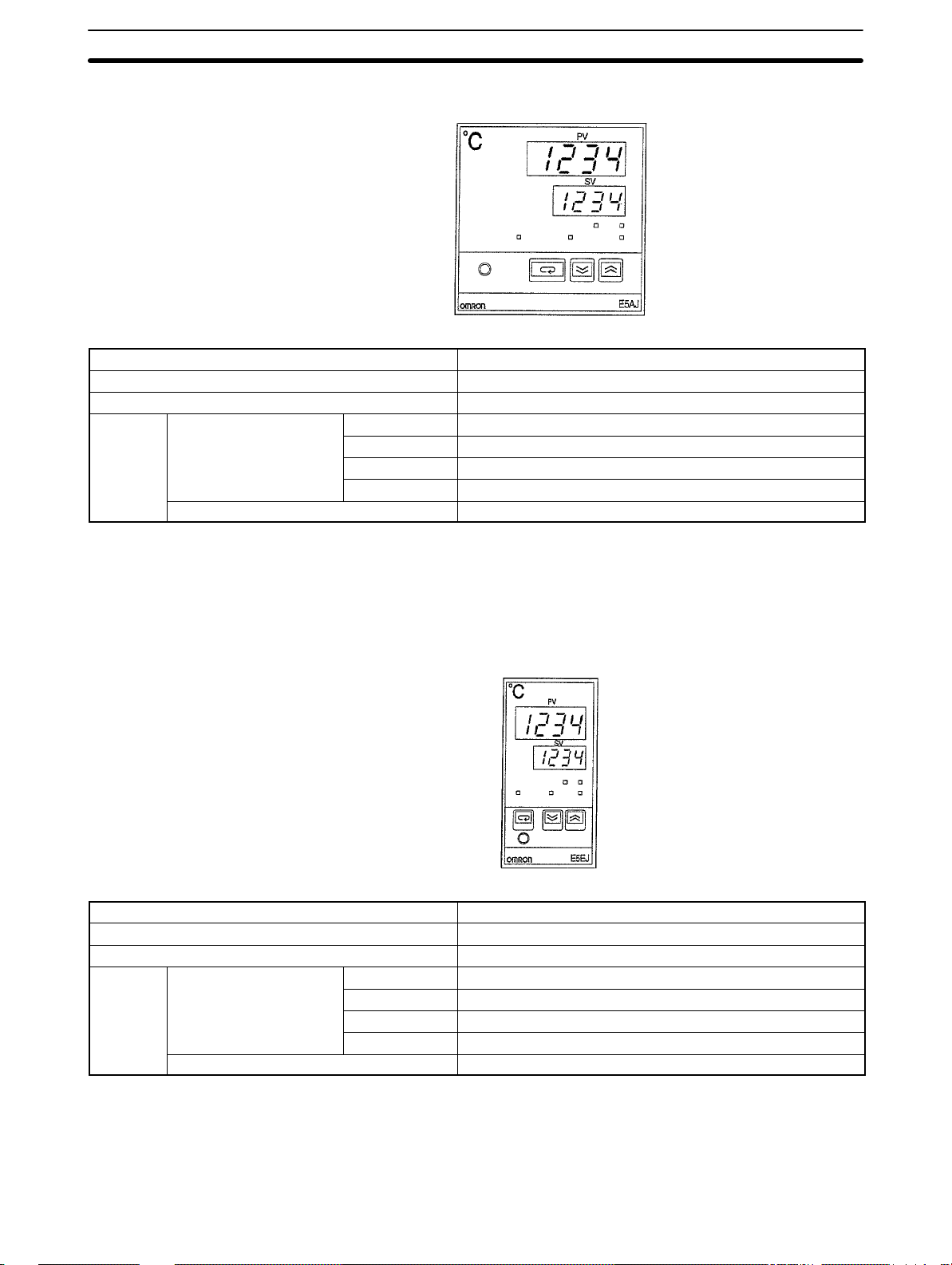
E5AJ (Standard Model with Communications Function)
96 X 96mm
Alarm 2 relay output points with heater burnout alarm (see note 1)
Event input 2 points (set point selection, RUN/STOP) (see note 2)
Control output Replaceable Output Unit (sold separately)
Model Communications function --- E5AJ-A2HB
RS-232C E5AJ-A2H01
RS-422 E5AJ-A2H02
RS-485 E5AJ-A2H03
Communications Board add-on model E5AJ-A2HM
Note 1. No heater burnout alarm is output if the E53-C3 Current Output Unit is used
with the E5AJ.
2. The event input function is not incorporated by models that have a communications function.
E5EJ (Standard Model with Communications Function)
48 X 96mm
Alarm 2 relay output points with heater burnout alarm (see note 1)
Event input 2 points (set point selection, RUN/STOP) (see note 2)
Control output Replaceable Output Unit (sold separately)
Model Communications function --- E5EJ-A2HB
RS-232C E5EJ-A2H01
RS-422 E5EJ-A2H02
RS-485 E5EJ-A2H03
Communications Board add-on model E5EJ-A2HM
Note 1. No heater burnout alarm is output if the Linear Output Unit is used with the
E5EJ.
2. The event input function is not incorporated by models that have a communications function.
3
Page 9
6 (at C)
Specifications
Section 1-3
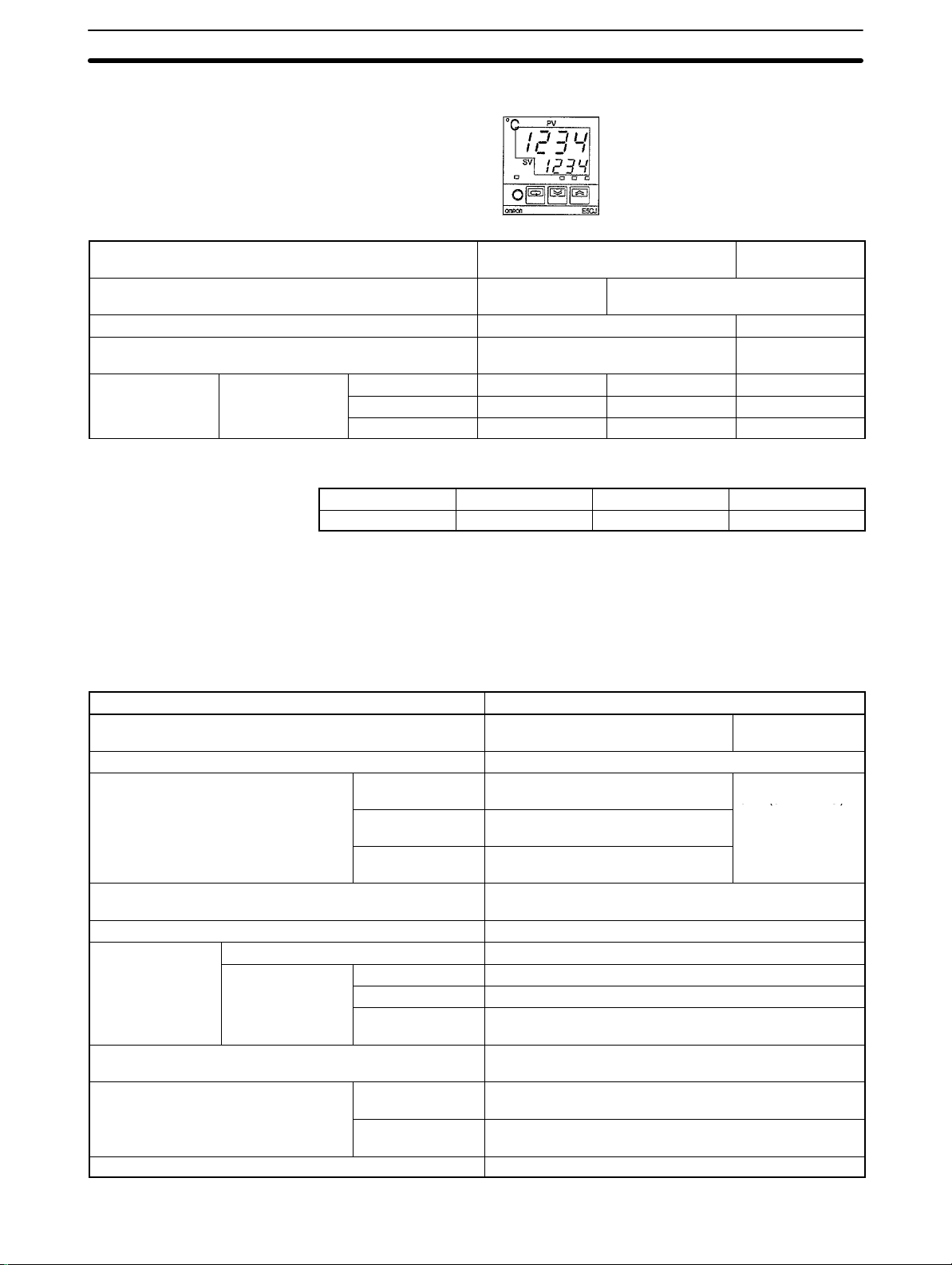
E5CJ (Simple and Standard Models)
48 X 48mm
Type Simple model type Standard model
type
Alarm --- 2 replay output points with the same
common. (see note 1)
Heater burnout alarm --- Yes (see note)
Event input --- 1 point (set point
selection)
Model Control output Relay output E5CJ-R E5CJ-R2 E5CJ-R2HB
Voltage output E5CJ-Q E5CJ-Q2 E5CJ-Q2HB
Current output E5CJ-C E5CJ-C2 E5CJ-C2B
Note No heater burnout alarm is output if a current control output is used.
Communications Boards
Note For details, refer to the
Communications RS-232C RS-422 RS-485
Model E53-J01 E53-J02 E53-J03
E5AJ/E5EJ Communications Manual (Z102).
1-3 Specifications
1-3-1 Ratings
E5J
Item Specification
Supply voltage 100 to 240 VAC, 50 or 60 Hz 24 V AC/DC,
50 or 60 Hz
Operating voltage range 85 to 110% of supply voltage
Power consumption E5AJ 10 VA (at 100 VAC) to
14 V A (at 240 VAC)
E5EJ 10 VA (at 100 VAC) to
14 V A (at 240 VAC)
E5CJ 10 VA (at 100 VAC) to
12 V A (at 240 VAC)
Input Thermocouples (K, J, T, L, U, and N) and platinum
resistance thermometers (JPt100 and Pt100)
CT input Dedicated CT (E54-CT1 or E54-CT3)
Control output E5AJ/E5EJ Replaceable Output Unit (sold separately)
E5CJ Relay output SPST-NO, 3 A at 250 VAC (resistive load)
Voltage output 20 mA at 12 VDC (with short-circuit protection)
Current output 4 to 20 mA DC with a load of 600 Ω max. and a
resolution of approx. 2600
Control mode ON/OFF or advanced PID with fuzzy self-tuning and
auto-tuning
Alarm output E5AJ/E5EJ 2 SPST-NO relay output points, 3 A at 250 VAC
(resistive load)
E5CJ 2 SPST-NO relay output points (with the same common),
1 A at 250 VAC (resistive load)
Setting method Digital setting with Up Key and Down Key
10 V A (at 24 VAC)
6 W (at 24 VDC)
4
Page 10

Specifications
Item Specification
Indication method E5AJ All digital indication (PV: Red, 15 mm; SV: Green,
10.5 mm)
E5EJ All digital indication (PV: Red, 14 mm; SV: Green,
9.5 mm)
E5CJ All digital indication (PV: Red, 12 mm, SV: Green 8.0
mm)
Event input Contact input: ON: 1 kΩ max. OFF: 100 kΩ min.
No-contact input: ON: residual voltage of 3 V max; OFF:
current leakage of 1 mA max.
Other function • Key protect
• Cooling operation/Heating operation
• Heater burnout alarm
Model with event input (E5J-B)
• Set point selection (set point x 2)
• RUN/STOP (E5AJ-B and E5EJ-B only)
Ambient operating temperature –10°C to 55°C (with no condensation)
Ambient operating humidity 35 to 85%
Storage temperature –25°C to 65°C (with no condensation)
Section 1-3
Output Units
Model Specification
E53-R Relay Output Unit SPDT (SPST-NO when used with the
E5J), 5 A at 250 VAC (resistive load)
E53-Q Voltage Output Unit NPN, 40 mA at 12 VDC (with
short-circuit protection)
E53-Q3 Voltage Output Unit NPN, 20 mA at 24 VDC (with
short-circuit protection)
E53-Q4 Voltage Output Unit PNP, 20 mA at 24 VDC (with
short-circuit protection)
E53-C3 Linear Output Unit 4 to 20 mA DC with a load of 600 Ω
max. (with a resolution of approximately
2600 when used with the E5J) (see
note)
E53-C3D Linear Output Unit 0 to 20 mA DC with a load of 600 Ω
max. (with a resolution of approximately
2600 when used with the E5J)
E53-V34 Linear Output Unit 0 to 10 VDC with a load of 1 kΩ min.
(with a resolution of approximately 2600
when used with the E5J)
E53-V35 Linear Output Unit 0 to 5 VDC with a load of 1 kΩ min.
(with a resolution of approximately 2600
when used with the E5J)
Note The E53-C cannot be used.
Current Transformer (CT)
Item Specification
Maximum continuous heater current 50 A
Dielectric strength 1,000 VAC
Vibration resistance 50 Hz, approx. 98 m/s2 (10G)
Weight E54-CT1: Approx. 11.5 g
E54-CT3: Approx. 50 g
5
Page 11

Specifications
Section 1-3
1-3-2 Characteristics
E5J
Item Specification
Indication accuracy ±0.5% or ±1°C whichever is larger ± 1 digit max.
Thermocouple K, T, or N at a temperature of –100°C; thermocouple U at ± 2°C ± 1
digit max.
Hysteresis (for ON/OFF control) 0.1 to 999.9°C/° F (in units of 0.1°C/°F)
Proportional band 0.1 to 999.9°C/°F (in units of 0.1°C/°F)
Integral time 0 to 3999 s (in units of 1 s)
Derivative time 0 to 3999 s (in units of 1 s)
Control period Relay or voltage output:1 to 99 s (in units of 1 s)
Manual reset value (I = 0) 0.0 to 100.0% (in units of 0.1%)
Alarm setting range With K, J, L, or N input: –1999 to 9999° C/°F (in units of 1°C/°F)
With JPt100, Pt100, T, or U input: –199.9 to 999.9° C/°F (in units of 0.1°C/°F)
Sampling period 500 ms
Output refresh period 500 ms
Display refresh period 500 ms
Insulation resistance 20 MΩ min. at 500 VDC (measured with an Output Unit)
Dielectric strength 2000 VAC, 50/60 Hz for 1 min. between charged terminals different from each other
in polarity
Vibration
resistance
Shock resistance Malfunction 196 m/s2 (20G) 3 times each in 3-axis 6 directions (98 m/s2 (10G) for the relay)
Weight E5AJ Approx. 360 g; mounting bracket: approx. 65 g
Enclosure rating Front panel: E5AJ/E5EJ: IEC standard IP54
Memory Protection Non-volatile memory
EMC Emission Enclosure: EN55011 Group 1 class A
Approved standards UL1092, CSA C22.2 No. 142
Malfunction 10 to 55 Hz, 9.8 m/s2 (1G) 10 min. in X, Y, and Z directions
Destruction 10 to 55 Hz, 19.6 m/s2 (2G) 2 hr. in X, Y, and Z directions
Destruction 294 m/s2 (30G) 3 times each in 3-axis 6 directions
E5EJ Approx. 280 g; mounting bracket: approx. 65 g
E5CJ Approx. 170 g; adapter: approx. 10 g
E5CJ: IEC standard IP50 (see note 1)
Rear case: IEC standard IP20
Terminals: IEC standard IP00
Emission AC Mains: EN55011 Group 1 class A
Immunity ESD: EN61000-4-2:4 kV contact discharge (level 2)
8 kV air discharge (level 3)
Immunity RF-interference: ENV50140: 10 V/m (amplitude modulated,
80 MHz to 1 GHz) (level 3)
10 V/m (pulse modulated,
900 MHz)
Immunity Conducted Disturbance: ENV50141: 10 V (0.15 to 80 MHz) (level 3)
Immunity Burst: EN61000-4-4:2 kV power-line (level 3)
2 kV I/O signal-line (level 4)
Conforms to EN50081-2, EN50082-2, EN61010-1 (IEC1010-1) (see note 2)
Conforms to VDE0106/part 100 (Finger Protection), when the separately-ordered
terminal cover is mounted.
Note 1. The model numbers of the exclusive watertight covers conforming to IP66,
NEMA4 are as follows:
For E5AJ: Y92A-96N; For E5CJ: Y92A-48N; For E5EJ: Y92A-49N
2. Basic insulation is between the input and output.
6
Page 12

Specifications
Section 1-3
Output Unit
Heater Burnout Alarm
Note 1. Use the K2CU-FA-GS (with gate input terminals) for the detection of
Model with
Communications Function
Model Life expectancy
E53-R Relay Output Unit Mechanical 10,000,000 times min.
Electrical 100,000 times min.
Item Specification
Max. heater current Single-phase 50 A VAC (see note 1)
Heater current value display accuracy ±5% FS ± 1 digit max.
Heater burnout alarm setting range 0.1 to 49.9 A (in units of 0.1 A)
Min. detection ON time 190 ms (see note 3)
(see note 2)
three-phase heater burnout.
2. The heater burnout alarm is always OFF if the alarm is set to 0.0 A and always ON if the alarm is set to 50.0 A.
3. No heater burnout detection or heater current value measurement is possible if the control output is ON for less than 190 ms.
Refer to the
Interface RS-232C, RS-422, RS-485
Communications method Half duplex
Synchronization method Start-stop synchronization
Communications speed 1200, 2400, 4800, 9600, and 19200 bps
Communications
item
E5AJ/E5EJ Communications Manual (Z102)
Item Specification
(non-synchronization)
Writing to
Thermac J
Reading from
Thermac J
Set point, alarm value, heater burnout alarm
value, proportional band, derivative time,
integral time, and input shift value
Process value, set point, alarm value, heater
burnout alarm value, heater current value,
proportional band, derivative time, integral
time, output value, input shift and error code
for details.
7
Page 13

SECTION 2
Sensor and Mode Settings
This section describes the sensor and mode settings of the Thermac E5J Temperature Controller that are necessary before
turning on the Thermac E5J Temperature Controller.
2-1 Disassembly 10. . . . . . . . . . . . . . . . . . . . . . . . . . . . . . . . . . . . . . . . . . . . . . . . . . . . . . . . . . . . .
2-2 Output Units 10. . . . . . . . . . . . . . . . . . . . . . . . . . . . . . . . . . . . . . . . . . . . . . . . . . . . . . . . . . . . .
2-3 Internal Switch Settings 11. . . . . . . . . . . . . . . . . . . . . . . . . . . . . . . . . . . . . . . . . . . . . . . . . . . .
2-3-1 Internal Switch Positions 11. . . . . . . . . . . . . . . . . . . . . . . . . . . . . . . . . . . . . . . . . . . .
2-3-2 Input Type Selector Setting 12. . . . . . . . . . . . . . . . . . . . . . . . . . . . . . . . . . . . . . . . . .
2-3-3 Alarm Mode Setting 13. . . . . . . . . . . . . . . . . . . . . . . . . . . . . . . . . . . . . . . . . . . . . . . .
2-3-4 Standby Sequence 14. . . . . . . . . . . . . . . . . . . . . . . . . . . . . . . . . . . . . . . . . . . . . . . . .
2-3-5 Function Selector Settings 14. . . . . . . . . . . . . . . . . . . . . . . . . . . . . . . . . . . . . . . . . . .
2-3-6 Key Protection Switch Settings 15. . . . . . . . . . . . . . . . . . . . . . . . . . . . . . . . . . . . . . .
9
Page 14
Output Units
2-1 Disassembly
2-2 Output Units
Section 2-2
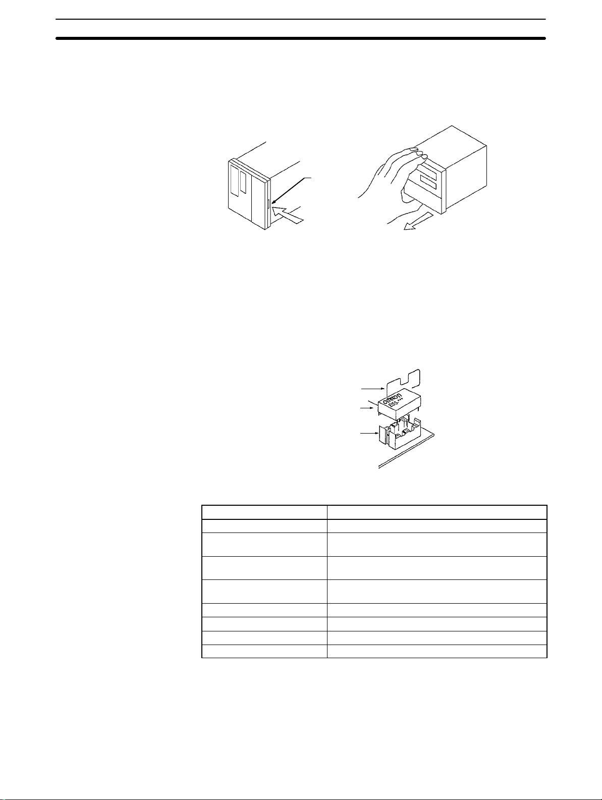
Before turning on the E5J, set its sensor type and control mode with the internal selectors. Refer to the following illustrations for disassembling the E5J to
access the internal switch settings.
Hook
Press the hook and
pull the front panel.
After setting the internal switches, insert the internal mechanism into the case
until the front panel snaps with the hook.
Select the Output Unit according to the application and mount the Output Unit
into the socket on the E5J PCB of the as shown in the following illustration. The
E5CJ does not require an Output Unit. Refer to
ratings of the E5J.
1-3 Specifications
for the output
Bracket
Output Unit
Socket
Output Units The following Output Units are available.
Model Rating
E53-R Relay Output Unit SPDT, 5 A at 250 VAC (resistive load)
E53-Q Voltage Output Unit NPN model, 40 mA at 12 VDC (with short-circuit
protecting circuit)
E53-Q3 Voltage Output Unit NPN model, 20 mA at 24 VDC (with short-circuit
protecting circuit)
E53-Q4 Voltage Output Unit PNP model, 20 mA at 24 VDC (with short-circuit
protecting circuit)
E53-C3 Linear Output Unit 4 to 20 mA DC with a load of 600 Ω max.
E53-C3D Linear Output Unit 0 to 20 mA DC with a load of 600 Ω max.
E53-V34 Linear Output Unit 0 to 10 VDC with a load of 1 kΩ min.
E53-V35 Linear Output Unit 0 to 5 VDC with a load of 1 kΩ min.
After mounting the Output Unit, be sure to secure it with the mounting bracket
provided with the Output Unit.
If the E53-C3, E53-C3D, E53-V34, and E53-V35 Linear Output Unit is used for
control output, no heater burnout alarm is available.
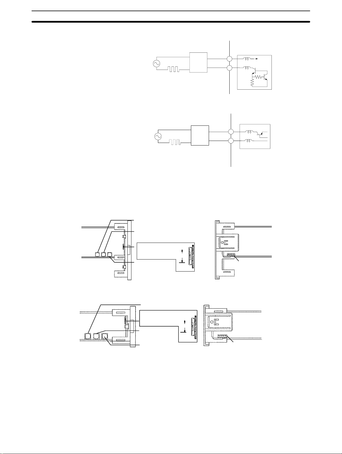
Each Voltage Output Unit is used for driving an SSR as shown in the following
illustrations.
10
Page 15
Internal Switch Settings
NPN Model: E53-Q (40 mA at 12 VDC) and E53-Q3 (20 mA at 24 VDC)
++
LOAD INPUT
PNP Model: E53-Q4 (20 mA at 24 VDC)
LOAD INPUT
SSR
––
++
SSR
––
Section 2-3
2-3 Internal Switch Settings
2-3-1 Internal Switch Positions
E5AJ
Top view
E5EJ
Top view
ALM2
Alarm mode selector 2
ALM1
Alarm mode selector 1
PROTECT
Key protection
switch
INPUT
Input type
selector
ALM2
Alarm mode selector 2
PROTECT
Key protection
switch
ALM1
Alarm mode
selector 1
INPUT
Input type selector
ALL
OFF
SP
ALL
OFF
SP
Bottom view
FUNCTION
Function selector
FUNCTION
Function selector
11
Page 16
Internal Switch Settings
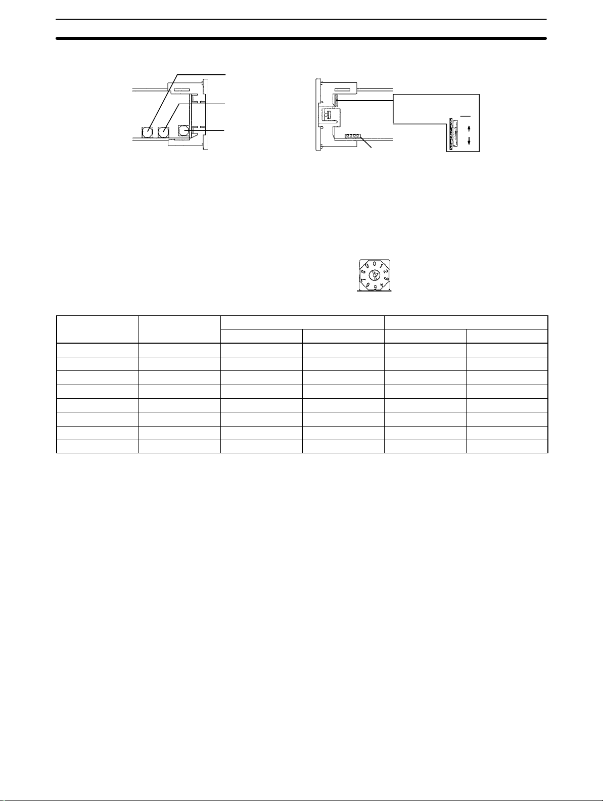
E5CJ
Top view
ALM2
Alarm mode selector 2
Section 2-3
Bottom view
ALM1
Alarm mode selector 1
INPUT
Input type selector
FUNCTION
Function selector
PROTECT
Key protection
switch
SP
OFF
ALL
Note The E5CJ with no alarm does not incorporate ALM1 or ALM2.
2-3-2 Input Type Selector Setting
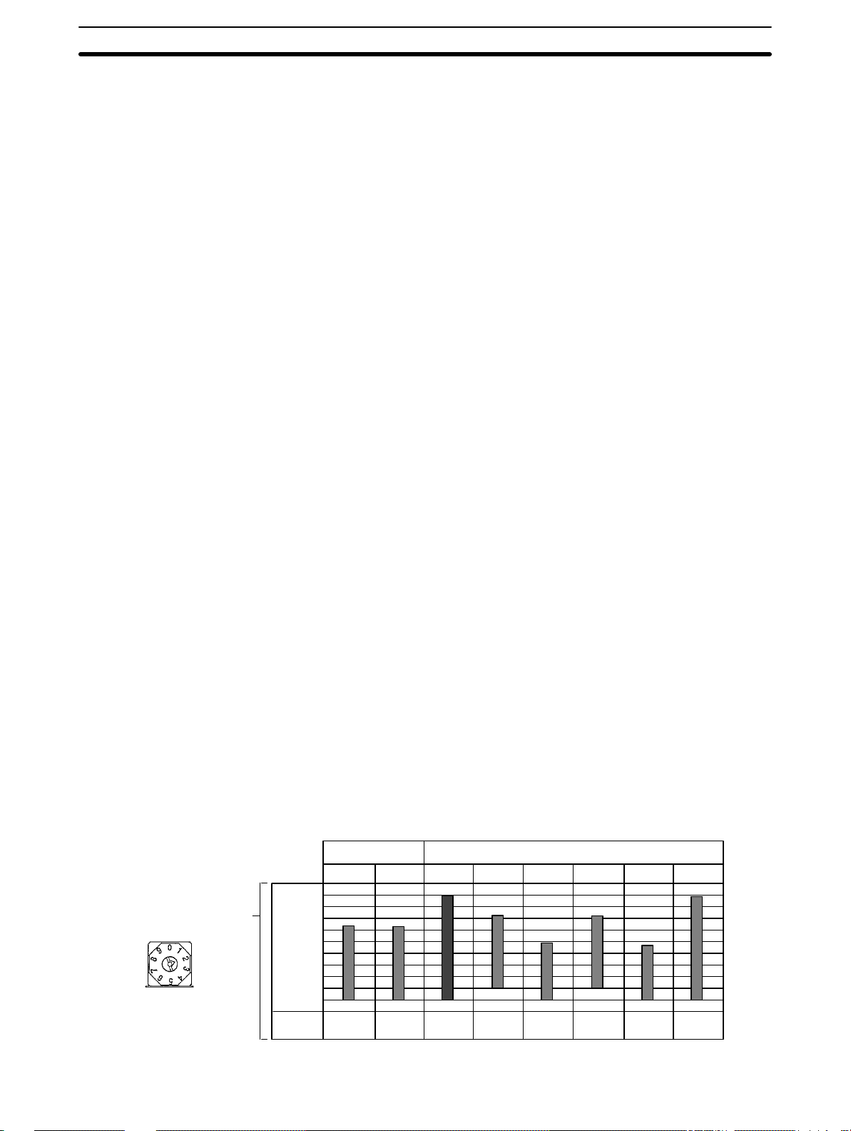
The input type selector is factory-set to 2 (K). Refer to the following table for the selection
of the desired sensor.
INPUT
Selector no. Input Set temperature range Specified temperature range
°C °F °C °F
0, 8 JPt100 –199.9 to 650.0 –199.9 to 999.9 –199.9 to 735.0 –199.9 to 999.9
1, 9 Pt100 –199.9 to 650.0 –199.9 to 999.9 –199.9 to 735.0 –199.9 to 999.9
2 K –200 to 1300 –300 to 2300 –350 to 1450 –560 to 2560
3 J –100 to 850 –100 to 1500 –195 to 945 –260 to 1660
4 T –199.9 to 400.0 –199.9 to 700.0 –199.9 to 460.0 –199.9 to 790.0
5 L –100 to 850 –100 to 1500 –195 to 945 –260 to 1660
6 U –199.9 to 400.0 –199.9 to 700.0 –199.9 to 460.0 –199.9 to 790.0
7 N –200 to 1300 –300 to 2300 –350 to 1450 –560 to 2560
Note The resistance of the JPt100 at a temperature of 100°C is 139.16 Ω and that of
the Pt100 at a temperature of 100°C is 138.50 Ω.
1, 2, 3...
1. To use Fahrenheit, set function selector 4 to ON, which is usually set to OFF.
2. Insert the internal mechanism into the case.
3. Turn on the E5J so that d-u will be displayed on the process value display.
Then press the Up Key so that f will be displayed on the set value display .
4. Turn off the power in two seconds.
5. Draw the internal mechanism from the case and set function selector 4 to
OFF and turn on the E5J.
12
Page 17
Internal Switch Settings
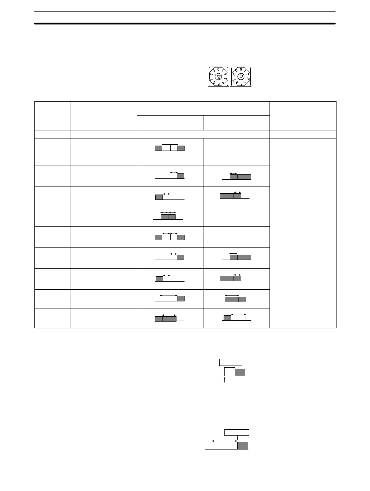
2-3-3 Alarm Mode Setting
ALM1 and ALM2 are both factory-set to 2 (upper limit alarm). Refer to the following table for the selection of the desired alarm mode.
Section 2-3
ALM2 ALM1
Selector
Alarm mode Alarm output Setting range
no.
Positive alarm set
value
Negative alarm set
value
0 No alarm function OFF --1 Upper and lower limit
alarm (deviation)
XSPX
Always ON –1999 to 9999 or –199.9
to 999.9 (the decimal
position varies with the
input type)
2 Upper limit alarm
(deviation)
3 Lower limit alarm
(deviation)
4 Upper and lower limit
SP
X
SP
XSPX
X
Always OFF
X
SP
X
SP
range alarm (deviation)
5 Upper and lower limit
XSPX
Always OFF
alarm with standby
sequence (deviation)
6 Upper limit alarm with
standby sequence
(deviation)
7 Lower limit alarm with
standby sequence
(deviation)
8 Absolute value upper
limit alarm
9 Absolute value lower
limit alarm
X
SP
X
SP
X
0
X
0
X
SP
X
SP
X
0
X
0
If the alarm mode switch is set to 1 to 7, the alarm value is set with the deviation
width from the set point as shown in the following diagram.
Alarm value
10°C/°F
Set point (SP)
100°C/°F
If the alarm mode switch is set to 8 or 9, the alarm value is set with the absolute
value from 0°C/°F as shown in the following diagram.
Alarm value
110°C/°F
0°C/°F
13
Page 18
Internal Switch Settings
2-3-4 Standby Sequence
The alarm output is ON the moment the E5J is turned on because the process
value is within the alarm range. To prevent this, select a mode with a standby
sequence. If a mode with a await sequence is selected, the alarm output will not
be ON even if the process value is within the alarm range unless the process
value once goes out of the alarm range. The following diagram shows the operation of the E5J in lower limit alarm mode with a standby sequence.
OFF point due to
alarm hysteresis
It is possible to change the alarm hysteresis (set to 0.2°C before shipping) on the
engineering level.
2-3-5 Function Selector Settings
All the function selector pins are factory-set to OFF.
Section 2-3
Standby sequence releasing
point
Alarm point
Alarm output
ON
OFF
To set these pins to
FUNCTION
ON, use a small flatblade screwdriver.
Refer to the following table for function switch setting.
Pin no. 1 2 3 4
Output Cooling operation (Normal) ON --- --- --operation Heating operation (Reverse) OFF
Control ON/OFF control --- ON See note
mode Advanced PID --- OFF ON
Advanced PID with fuzzy self-tuning --- OFF OFF
Level Engineering level --- --- --- ON
Normal operation --- --- --- OFF
Note The E5 J will be in ON/OFF control mode regardless of the setting of pin 3 if pin
2 is set to ON.
Output Operation (Pin 1)
Heating Operation If pin 1 of the E5J is set to OFF, when the process temperature is lower than the
set point, the E5J will operate so that the heater output will increase.
Cooling Operation If pin 1 of the E5J is set to ON, when the process temperature is higher than the
set point, the E5J will operate so that the output of cooling water will increase.
Control Mode (Pins 2 and 3)
ON/OFF Control The ON/OFF control is also called two-position operation.
Advanced PID Set the E5J in this mode for P, PI, or PD control or if the most suitable PID
constants for the controlled device are already known.
Advanced PID with Fuzzy
Self-tuning
Set the E5J in this mode so that Fuzzy self-tuning adjusts the PID constants to
the most suitable values according to the controlled device for ideal temperature
control. Refer to
Section 4 Fuzzy Self-tuning
for details.
Level (Pin 4)
14
Set pin 4 to ON if it is necessary to change any parameter on the engineering
level. Set this pin to OFF for normal operation.
Page 19

Internal Switch Settings
2-3-6 Key Protection Switch Settings
The key protection switch is used to prohibit parameter changes as shown in the
following table. The key protection switch is factory-set to OFF.
Mode Protection
SP
OFF All keys are available.
ALL Prohibits all set value changes. The Level Key, Down Key, and
Prohibits all set value changes except the set point. The Level
Key is not available. The Down Key and Up Key are available
only for set point setting.
Up Key are not available.
Section 2-3
SP OFF ALL
PROTECT
15
Page 20

SECTION 3
Settings Before Operation
This section describes the settings of the Thermac E5J Temperature Controller that are necessary before operating the
Thermac E5J Temperature Controller.
3-1 Nomenclature 18. . . . . . . . . . . . . . . . . . . . . . . . . . . . . . . . . . . . . . . . . . . . . . . . . . . . . . . . . . . .
3-2 Setting Flowchart 19. . . . . . . . . . . . . . . . . . . . . . . . . . . . . . . . . . . . . . . . . . . . . . . . . . . . . . . . .
3-3 List of Parameters 20. . . . . . . . . . . . . . . . . . . . . . . . . . . . . . . . . . . . . . . . . . . . . . . . . . . . . . . .
3-4 Parameters on Display Level 0 22. . . . . . . . . . . . . . . . . . . . . . . . . . . . . . . . . . . . . . . . . . . . . . .
3-5 Parameters on Display Level 1 23. . . . . . . . . . . . . . . . . . . . . . . . . . . . . . . . . . . . . . . . . . . . . . .
17
Page 21
Nomenclature Section 3-1
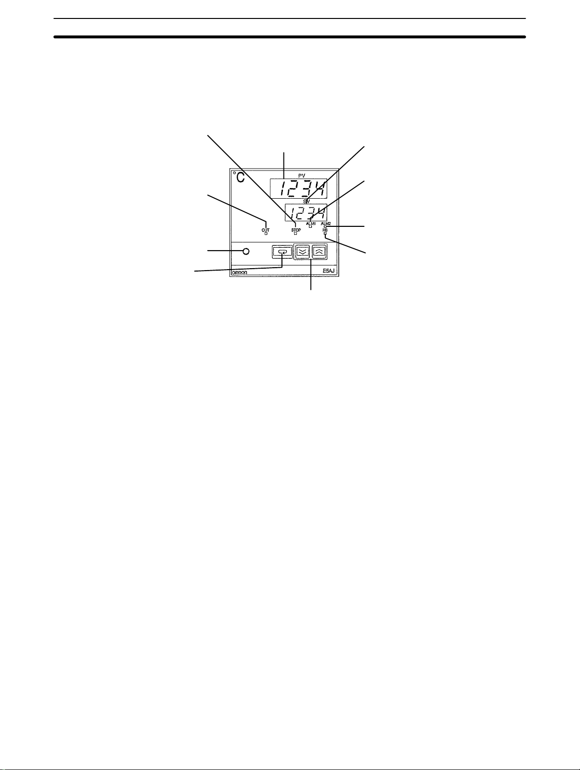
3-1 Nomenclature
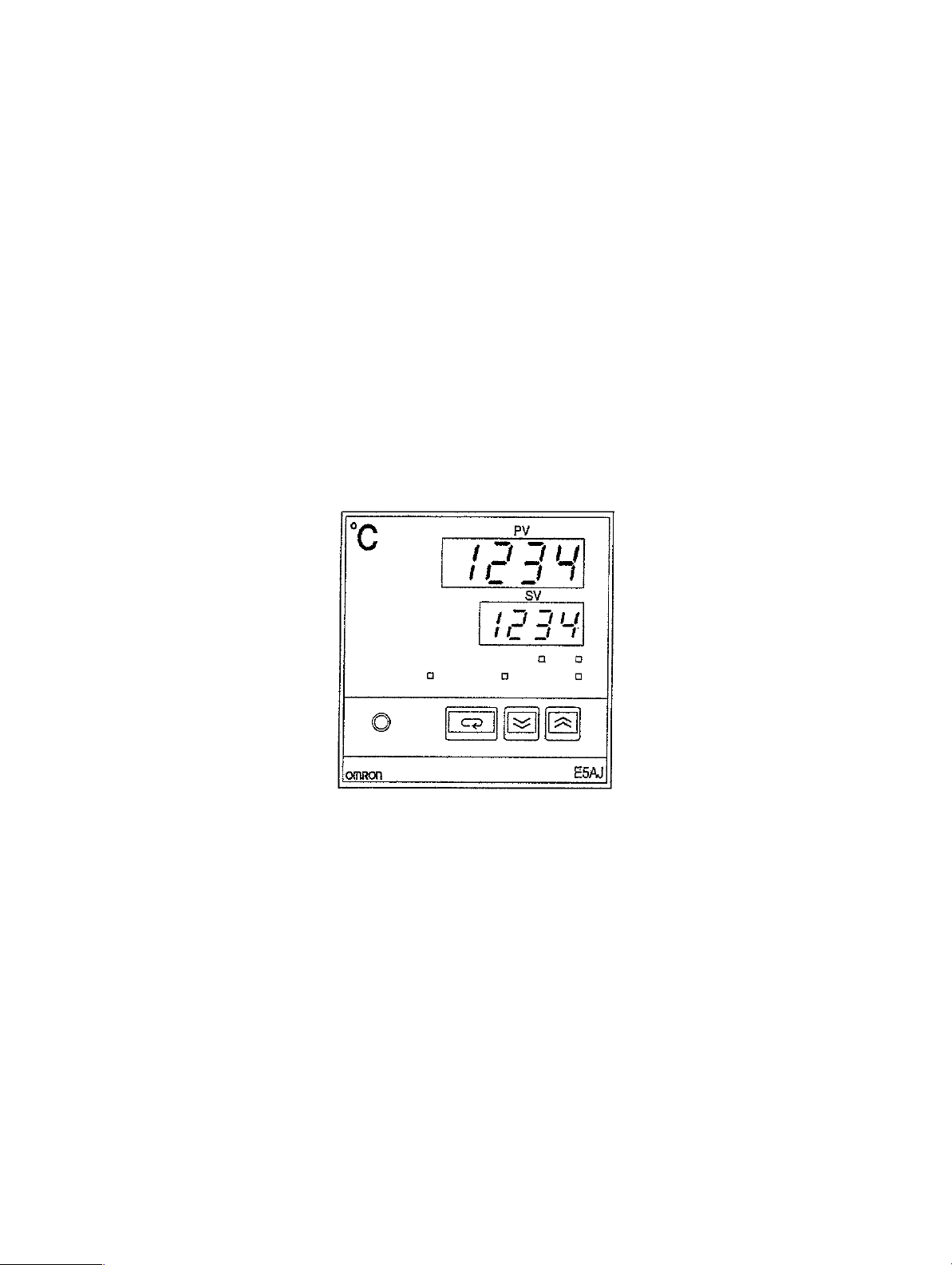
The following is the front panel of the E5AJ-A2HB. The front panels of the E5EJ
and E5CJ are similar to the front panel of the E5AJ-A2HB.
Process Value (PV) display
Displays not only the process
value but also indicates the pa-
Stop indicator
Lit when the E5J is not operating.
The E5CJ does not incorporate this
indicator.
Output indicator
Lit when the control output is ON.
This indicator is, however, not lit
when the E5J has a current output.
Level Key
Press for 1 s minimum to change levels to set different groups of parameters.
Display Key
Use this key when shifting the
display to the next parameter.
rameter being displayed on the
SV display and error messages.
Down Key and Up Key
The Down Key, when pressed, decreases the set temperature or other parameters. The value successively decreases
when the Down Key is held down for 1 s minimum. The Up
Key, when pressed, increases the set temperature or other
parameters. The value successively increases when the Up
Key is held down for 1 s minimum. The value set will be effective on pressing the Display Key or Level Key or 2s after it
is set if Display Key or Level Key is not pressed.
Set Value (SV) display
Displays the set temperature
and other parameters.
Alarm 1 indicator
Lit when alarm output 1 is ON.
Alarm 2 indicator
Lit when alarm output 2 is ON.
Heater burnout alarm
Lit when there is heater burnout.
Once heater burnout is detected, the
alarm output will be on hold.
Note Refer to the
E5AJ/E5EJ Communications Manual
models incorporating a communications function.
for the operation of E5J
18
Page 22

Setting Flowchart
Section 3-2
3-2 Setting Flowchart
The Thermac E5J Temperature Controller starts control at the set point and
continues controlling even while set values are being input for each display level.
Therefore, when operating the E5J after inputting all the set values, turn the
power supply to the Temperature Controller off and then on again.
All parameters for the E5J Temperature Controller are divided into three levels
according to how frequently they are used.
Display Level 0 Parameters that are changed frequently are ranked as display level 0 parame-
ters.
Display level 1 Parameters that are not changed frequently are ranked as display level 1 pa-
rameters.
Engineering Level Parameters that are changed with only a few applications are ranked as engi-
neering level parameters.
OFF ON
Level Key
Press for 1 s min.
Display level 0 Display level 1
Set point setting
Alarm 1 setting
Alarm 2 setting
Each parameter is set with the Up Key or Down
Key. Each value set will be effective on pressing
the Display Key or Level Key or 2 s after it is selected if Display Key or Level Key is not pressed.
No value can be, however, changed when the
key protection switch is ON.
The parameters in parentheses are changed if their initial
values are changed on the engineering level.
Level Key
Press for 1 s min.
Output display
Control period setting
Hysteresis setting
Set point 0 setting
Set point 1 setting
(Set point 2 setting)
(Set point 3 setting)
(Input shift value setting)
Heater current value display
Heater burnout alarm setting
Proportional band setting
Integral time setting
Derivative time setting
Manual reset value setting
Pin 4 of the func-
tion selector
Engineering level
°C/°F selection
Stable range
Alpha
Automatic return of display mode
Standby sequence reset method
Input shift display selection
Alarm 1 hysteresis
Alarm 2 hysteresis
Set point lower limit
Set point upper limit
Event input 2 function selection
Refer to
Settings
on the engineering level and how to
change them.
Section 9 Engineering Level
for details on each parameters
19
Page 23

List of Parameters
3-3 List of Parameters
Display Level 0
Display Name Setting range Setting
--- Process value
display and set
point setting
AL-1 Alarm set value 1 –1999 to 9999 °C/°F
AL-2 Alarm set value 2 –1999 to 9999 °C/°F
To go to the next level, press the Level Key for 1 s min.
Note The values shown in Fahrenheit are applicable only for E5J--F Mod-
els.
Set point lower limit
to set point upper
limit (°C/°F)
The decimal position
varies with the kind
of input.
The decimal position
varies with the kind
of input.
Section 3-3
Remarks
before
shipping
0 The present set point is
displayed and can be
changed if the E5J
incorporates an event input
function
0 Not displayed if alarm mode
switch 1 is set to 0.
0 Not displayed if alarm mode
switch 2 is set to 0.
Display Level 1
Display Name Setting/Display
0 Output value
display
CP Control period 1 to 99 s 20 Displayed and can be set if
HYS Hysteresis 0.1 to 999.9 °C/°F 1.0 (1.8) Displayed and can be set
SP-0 Set point 0 Set point lower limit
SP-1 Set point 1 Set point lower limit
SP-2 Set point 2 Set point lower limit
SP-3 Set point 3 Set point lower limit
in-S Input shift value –199.9 to 999.9 °C/°F 0.0 Displayed and can be set if
0.0 to 100.0 %
to set point upper
limit (°C/°F)
to set point upper
limit (°C/°F)
to set point upper
limit (°C/°F)
to set point upper
limit (°C/°F)
Range
Setting
before
shipping
the E5J in PID control
operation has relay control
output or voltage control
output.
when the E5J is in ON/OFF
control operation.
0 For models incorporating an
event input function.
0 For models incorporating an
event input function.
0 For models incorporating an
event input 2 function.
Displayed and can be set if
the default value is changed
on the engineering level.
0 For models incorporating an
event input 2 function.
Displayed and can be set if
the default value is changed
on the engineering level.
the default value is changed
on the engineering level.
Remarks
20
Page 24

List of Parameters
Section 3-3
Display RemarksSetting
Ct Heater current
Hb Heater burnout
P Proportional band 0.1 to 999.9 °C/°F 8.0 (14.4) Displayed and can be set
8.0
i Integral time 0 to 3999 s
d Derivative time 0 to 3999 s
oFr Manual reset value 0.0 to 100.0 % 50.0 Displayed and can be set if
Name
value display
alarm value
Setting/Display
Range
0.0 to 55.0 A
If the current exceeds
55.0 A, ffff will be
displayed on the set
value display.
0.0 to 50.0 A
0.0: Always OFF
50.0: Always ON
0: No integral
operation
0: No derivative
operation
before
shipping
0.0 For models incorporating a
233 Displayed and can be set
40 Displayed and can be set
For models incorporating a
heater burnout alarm.
Nothing is displayed if the
E5J has current control
output.
heater burnout alarm.
Nothing is displayed if the
E5J has current control
output.
when the E5J is in
advanced PID operation.
when the E5J is in
advanced PID operation.
when the E5J is in
advanced PID operation.
the integral time is set to 0
when the E5J is in
advanced PID operation.
Note The value in the parentheses is the E5J--F setting before shipping.
21
Page 25

Parameters on Display Level 0
3-4 Parameters on Display Level 0
Note: The process value will not be displayed if the
alarm mode switch is set to 0 or if the E5J does
not incorporate any alarm.
Section 3-4
The value set before
shipping appears
(Set point setting)
Displays when the E5J incorporates
an alarm function (see note).
(Alarm 1 setting)
Displays when the E5J incorporates
an alarm function (see note).
(Alarm 2 setting)
Set Point Setting (°C or °F) It is possible to alter the present set point (SP0 or SP1).
al1 and al2 (°C or °F) The alarm mode is factory-set to the upper limit alarm (deviation). It is possible to
change the alarm mode with the alarm mode selector. Refer to
Mode Setting
. The alarm value can be set with the deviation width or absolute
2-3-3 Alarm
value according to the alarm mode.
Deviation alarm Absolute value alarm
Upper and lower limit alarm, upper limit
alarm, lower limit alarm and upper and
lower limit range alarm.
Set with the deviation width from
the set point
Alarm value
10°C/°F
Set point (SP) 100°C/°F
Absolute value upper limit alarm and
absolute value lower limit alarm.
Set with the absolute value from 0°C/°F.
Alarm value
110°C/°F
0°C/°F
22
Page 26

Parameters on Display Level 1
3-5 Parameters on Display Level 1
Section 3-5
The value set before
shipping appears
(Output value display)
Displays when the E5J in PID control
operation has a relay or voltage output.
(Control period setting)
Displays when the E5J is in ON/
OFF control operation.
(Hysteresis setting)
Displays if the E5J has an
event input.
(Set point 0 setting)
(Set point 1 setting)
Displays only if the event input 2
function is used for set point selection (see note 1).
(Set point 2 setting)
(Set point 3 setting)
Displays if the input shift value display is selected (see note 1).
(Input shift value setting)
Displays if the heater burnout
alarm function is selected. (see
note 2).
(Heater current value
display)
(Heater burnout alarm
value setting)
Displays when the E5J in advanced PID operation.
8.0
(Proportional
band setting)*
*In case of °F:
(Integral time setting)
(Derivative time setting)
Displays if I is 0 .
(Manual reset value
setting)
14.4
Note 1. Displayed if the initial value is changed on the engineering level.
2. Not displayed if current output is used as control output or a model with no
heater burnout alarm function is used.
23
Page 27

Parameters on Display Level 1
Section 3-5
o Output Value Display The output value is displayed within a range of 0.0% to 100.0%.
cp Control Period Setting It is possible to set the control period within a range of 1 to 99 s. The control peri-
od is the period required by the E5J to turn ON and OFF its relay output or voltage output. The ON period increases in proportion to the output value. If the control period is short, smooth control operation will be possible although a short
control period shortens the life of the relay if relay output is used. Therefore, the
control period should not be less than 20 s if relay output is used. The following
are output examples with an output value of 50.0 %.
5 s 10 s
ON
ON
hys Hysteresis Setting (°C
or °F)
sp0, sp1, sp2, and sp3
(E5J-B Only)
OFF
Control period: 10 s Control period: 20 s
It is possible to set the hysteresis for the E5J in ON/OFF control operation within a range of 0.1° to 999.9°C/°F.
Heating
control
(Reverse)
Cooling
control
(Normal)
ON
OFF
Low temperature Set point High temperature
ON
OFF
Low temperature Set point High temperature
It is possible to set sp-0 (set point 0), sp-1 (set point 1), sp-2 (set point 2), and sp-3
(set point 3) all in Celsius or Fahrenheit regardless of the set point presently se-
OFF
Hysteresis
Hysteresis
lected. To select the set point, open or short-circuit terminals EV1 and EV2. Re-
Section 7 Event Input Function
fer to
for details.
in-s Input Shift Value It is possible to set the input shift value within a range of –199.9° to 999.9°C/°F.
When an input shift value is set, the process value will be the input value added
with the shift value.
Example
Input Input shift value Process value
100°C 0 (no compensation) 100°C
10.0 (compensation value) 110°C
–10.0 (compensation value) 90°C
ct Heater Current Value
Display (E5J-H Only)
hb Heater Burnout Alarm
Value Setting (E5J-H
Only)
24
After the input shift value is set, the it is effective even if the input shift value display is turned off on the engineering level.
It is possible to set the heater current value within a range of 0.0 to 55.0 A. If the
current value exceeds 55.0 A, ffff will be displayed on the set value display.
The heater current will be processed and displayed if the control output is ON.
It is possible to set the heater burnout alarm value within a range of 0.0 to 50.0 A,
which will be used to detect heater burnout. If the heater burnout alarm value is
set to 0.0 A, the heater burnout alarm output will be always OFF. If the heater
burnout alarm value is set to 50.0 A, the heater burnout alarm output will be always ON. Refer to
Section 8 Heater Burnout Detection
for details.
When the E5J is in advanced PID with fuzzy self-tuning mode, the following
parameters (p, i, d, ofr) will not be displayed (i.e., there is no need to set the
following parameters). The fuzzy self-tuning always adjusts the PID constants to
the most suitable values according to the characteristics of the controlled device.
Page 28

Parameters on Display Level 1
p Proportional Band Setting It is possible to set the proportional band within a range of 0.1 to 999.9°C/°F.
i Integral Time Setting It is possible to set the integral time within a range of 0 to 3999 s.
d Derivative Time Setting It is possible to set the derivative time within a range of 0 to 3999 s.
Section 3-5
ofr Manual Reset Value
Setting
It is possible to set the necessary output value when the E5J is in constant operation within a range of 0.0% to 100.0%. The E5J will be balanced with a deviation between the set point and process value in P or PD control mode. This
deviation is called offset. The offset can be removed by changing the manual
reset value.
25
Page 29

SECTION 4
Fuzzy Self-tuning
This section provides the procedures required to adjust all PID constants using fuzzy self-tuning according to the characteristics of the device for ideal temperature control.
4-1 Fuzzy Self-tuning Operation 28. . . . . . . . . . . . . . . . . . . . . . . . . . . . . . . . . . . . . . . . . . . . . . . .
4-1-1 Step Response Tuning (SRT) 28. . . . . . . . . . . . . . . . . . . . . . . . . . . . . . . . . . . . . . . . .
4-1-2 Disturbance Tuning (DT) 29. . . . . . . . . . . . . . . . . . . . . . . . . . . . . . . . . . . . . . . . . . . .
4-1-3 Hunting Tuning (HT) 30. . . . . . . . . . . . . . . . . . . . . . . . . . . . . . . . . . . . . . . . . . . . . . .
4-2 Troubleshooting 31. . . . . . . . . . . . . . . . . . . . . . . . . . . . . . . . . . . . . . . . . . . . . . . . . . . . . . . . . .
4-3 Terminology 32. . . . . . . . . . . . . . . . . . . . . . . . . . . . . . . . . . . . . . . . . . . . . . . . . . . . . . . . . . . . .
4-3-1 Stable Value, Stable Range, and Stability Judgement Time 32. . . . . . . . . . . . . . . . .
4-3-2 Hunting 33. . . . . . . . . . . . . . . . . . . . . . . . . . . . . . . . . . . . . . . . . . . . . . . . . . . . . . . . .
4-3-3 Characteristics and Characteristics Change 33. . . . . . . . . . . . . . . . . . . . . . . . . . . . . .
4-3-4 External Disturbance 33. . . . . . . . . . . . . . . . . . . . . . . . . . . . . . . . . . . . . . . . . . . . . . .
4-3-5 Interference 33. . . . . . . . . . . . . . . . . . . . . . . . . . . . . . . . . . . . . . . . . . . . . . . . . . . . . .
4-3-6 Startup 34. . . . . . . . . . . . . . . . . . . . . . . . . . . . . . . . . . . . . . . . . . . . . . . . . . . . . . . . . .
27
Page 30

Fuzzy Self-tuning Operation Section 4-1
4-1 Fuzzy Self-tuning Operation
The fuzzy self-tuning function has three features, step response tuning (SRT),
disturbance tuning (DT), and hunting tuning (HT).
4-1-1 Step Response Tuning (SRT)
SRT is used to obtain all PID constants using a step response method when the
Temperature Controller starts operations.
SRT is also used when the set point changes value exceeding a set range while
the Temperature Controller is operating. After SRT has been executed, no SRT
will be executed the next time the Temperature Controller starts operating, unless the set point has been changed.
Set point
Max. temperature slope R
Dead time L
Tuning at startup
P X 1.27
In step response tuning, control is completely imposed stepwise to measure the maximum temperature slope (R) and
dead time (L), and the most ideal PID constants for the device are obtained from R and L.
Output (%)
100
100% imposed
step-wise control
amount.
Note Be sure to turn on the power supply to the load either before or simultaneously
Advanced PID
with the start of Temperature Controller operation. When using the E5AJ-A2HB
or E5EJ-A2HB, you can change the RUN/STOP setting to RUN via event input
2 after supplying power to the load.
Dead time will be measured from the time the Temperature Controller starts
operating. If a load such as a heater is turned on after the Temperature Controller is turned on, dead time longer than the actual value will be measured and
inappropriate PID constants will be obtained. If an extremely large amount of
dead time is measured, the control amount will be set to 0% for a short period of
time before being returned to 100%, and the constants will then be retuned.
Retuning is performed only for large amounts of dead time, so be sure to follow
the precaution given above when starting operation.
28
Page 31

Fuzzy Self-tuning Operation Section 4-1
SRT Startup Condition SRT will be ON if the following conditions are satisfied simultaneously when the
Temperature Controller is turned on or the set point is changed.
Imposition Completion
Condition of Step Control
Amount
PID Constant Refreshing
Conditions
At the time the Temperature Controller
starts operating
1) The set point at the time the
Temperature Controller starts operating
is different from the set point used at
the time SRT was last executed (see
note).
2) The difference between the set point
and the process value at the time the
Temperature Controller starts operating
is larger than the present proportional
band value (P) x 1.27 + 4.
3) The process value at the time the
Temperature Controller starts operating
is smaller than the set point in reverse
operation and larger than the set point
in normal operation.
At the time set point is changed
1) The new set point is different from
the set point used at the time SRT
was executed last (see note).
2) The set point changing range is
larger than the present
proportional band value (P) x 1.27
+ 4.
3) The process value is in stable
condition before the set point is
changed.
4) A larger set point value is set in
reverse operation and a smaller
set point is set in normal operation.
Note The last SRT-executed set point is set to 0 before shipping and when changing
from advanced PID control to advanced PID control with fuzzy self-tuning.
In order to prevent overshooting, the step controlled amount must be imposed
continuously only while the present deviation is the same as or greater than the
value obtained from the proportional band (P)1.27. The step control will not be
applied when the deviation becomes smaller than this value.
If the step control amount is applied before the maximum temperature slope (R)
is obtained, SRT will not renew any PID constant. If the proportional band obtained from the R and L values that were measured before the imposition had
been completed is larger than the present proportional band, the PID constants
will be renewed because the measured value is in the direction towards the suitable proportional band value, and the set point at that time will be the SRTexecuted set point.
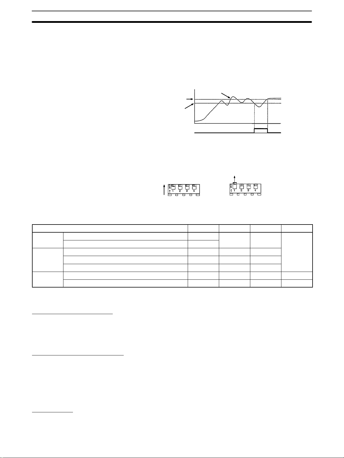
4-1-2 Disturbance Tuning (DT)
DT is used to measure the control waveform and adjust the PID constants when
the measured temperature becomes unstable. When there are control characteristic changes after the PID constants are refreshed with SRT or when the PID
constants are not suitable to the object to be controlled because SRT was not
executed, the PID constants will be adjusted with DT.
DT at the Time of Operation
Start and Set Value Change
Set point
PID before tuning PID after tuning
If there is overshooting at the time the Temperature Controller restarts operating
after SRT has been executed, DT adjusts the PID constants so that the set point
response waveform will be as close as possible to the most ideal response waveform aft e r i t i s deemed that there has been a characteristics change in the control system.
Stable range (set to 15.0°C before shipping)
Stability judgement time
Measurement of
set point response
waveform
The set point response waveform
at the time the Temperature Controller restarts operation will be
closer to the most ideal response
waveform.
29
Page 32

Fuzzy Self-tuning Operation Section 4-1
DT at the Time of External
Disturbance Response
After the process value reaches the set point and becomes stable, if the process
value is disturbed and the disturbance exceeds the stable range, the disturbance is regarded as external disturbance At the time of disturbance, DT measures the external disturbance waveform and adjusts the PID constants so that
the external disturbance waveform will be as close as possible to the most ideal
external disturbance response waveform.
Stable range
(set to 15.0°C before shipping)
Set point
External disturbance
Stability judgement time
Measurement of
external disturbance
response waveform
External disturbance
The external disturbance response waveform is approaching to
the most ideal response waveform even if the same kind of
external disturbance reoccurs. The waveform will not, however,
change if the most ideal PID constants are already set.
PID after tuningPID before tuning
Startup Conditions of DT DT is used to monitor the control waveform if there is external disturbance or
SRT does not work at the time the Temperature Controller starts operating or at
the time of set point change. If the measured waveform is not an ideal waveform,
DT will be ON. If either one of the following conditions is satisfied, the control
waveform will be monitored.
1, 2, 3...
1. SRT Startup conditions 3 and 4 on page 29 are satisfied but neither 1 nor 2 is
satisfied.
2. There has been an external disturbance exceeding the stable range after
the process value was in stable condition.
Note The stable range is set to 27°F with the E5J--F.
4-1-3 Hunting Tuning (HT)
If there is hunting due to characteristics changes of the control system, HT is
used to measure the hunting waveform and adjust the PID constants to suppress the hunting.
Set point
PID before tuning PID after tuning
Extreme value
Stable range
(set to 15.0°C before shipping)
Measurement of
hunting waveform
Startup Conditions of HT HT will be ON when there is hunting with four or more maximum temperature
values while SRT is not being executed.
Note If the periodic temperature changes of the application exceed the stable range
(set to 15.0°C at the factory) due to continuous external disturbance (i.e., the
temperature is a ffected by an external disturbance before stabilizing after a previous external disturbance (refer to figure A below)), the user should change the
stable range to a value greater than the temperature changing range, otherwise
30
Page 33

Troubleshooting
Section 4-2
HT may change the PID constants even though the PID constants are ideal for
the control system. Refer to
External disturbance
Figure A: Waveform with HT turned ON
External disturbance
9-1 Engineering Level
for details.
Note The stable range is set to 27°F with the E5J--F.
4-2 Troubleshooting
Fuzzy self-tuning may not exhibit its full capability due to the characteristics and
conditions of the controlled object.
Refer to the following table for troubleshooting when Unit operation is not
smooth.
Phenomenon Probable cause Countermeasure
The temperature does not reach the
set point.
T1 T2
Figure B: Waveform with HT turned OFF
The dead time measured was longer
than the actual value and
inappropriate PID constants were
obtained because the load (such as a
heater) was turned on after the
Temperature Controller started
operating. (Refer to
details.)
The PID constants were changed from
the most ideal value because HT is
ON continuously when there was a
periodic temperature change larger
than the stable range due to an
external disturbance. Refer to the note
under 4-1-3.
4-3-6 Startup
for
T1<T2
Do the following to execute SRT
again.
1) Set the control mode to the
advanced PID and set the
proportional band to 0.1°C.
2) Set the control mode to the
advanced PID with fuzzy
self-tuning again.
3) Wait until the temperature of the
control system is stable, and then
turn on the Temperature Controller
and the load simultaneously or
turn on the load first for SRT.
Do either one of the following so that
HT will not be ON.
• Change the stable range to a
wider setting than the range of the
temperature change and execute
SRT again by executing steps 1)
to 3) above.
• After obtaining the most ideal PID
constants by executing steps 1) to
3) above, set the control mode to
advanced PID.
31
Page 34

Terminology
Phenomenon CountermeasureProbable cause
Hunting does not stop. The control period is too long for the
characteristics of the controlled
device, which causes hunting in
synchronization with the control
period.
The temperature is influenced by
continuous external disturbance (i.e.,
the temperature is affected by an
external disturbance before a previous
disturbance has be stabilized. and it
looks as if hunting did not stop at all).
The response fluctuates, becoming
good and bad.
The response fails to reach
operational requirements.
There is a heater or cooling device not
controlled by the control output of the
Temperature Controller (e.g., forced
heating or cooling is executed using
alarm outputs).
There are continuous characteristics
changes.
The response speed of the controlled
device is so fast that it cannot be
retrieved by a sampling period of 500
ms.
The temperature is affected by
devices near the system.
Section 4-3
Shorten the control period.
In this case, however, 100%
improvement will not be possible
because the temperature is influenced
by a continuous external disturbance
instead of hunting. Change the stable
range to a wider setting than the
range of the temperature change so
that HT will not be ON.
In this case fuzzy self-tuning may not
work. Set the control mode to the
advanced PID and adjust the PID
constants manually.
Do either one of the following.
• Adjust the stable range so that
fuzzy self-tuning will not be turned
ON.
• Set the control mode to the
advanced PID and adjust the PID
constants manually.
The Thermac E5J Temperature
Controller cannot support a sampling
period of less than 500 ms. Use an
ES100-series Digital controller, which
has a shorter sampling period.
Fuzzy self-tuning does not support
any countermeasure against
interference. Set the control mode to
the advanced PID and adjust the PID
constants manually.
4-3 Terminology
4-3-1 Stable Value, Stable Range, and Stability Judgement Time
If the measured value continuously coincides with the set point, it can be said
that the measured value is stable. The measured value will not continuously
coincide perfectly with the set point if there is noise inference. It is, however, possible to make the measured value stay within a permissible range called the
stable range. Even if the temperature is within the stable range, the Temperature
Controller may respond to external disturbance or hunting. Therefore, it cannot
be said that the temperature is stable unless the temperature stays within the
stage range continuously for a certain time. This time is called stability judgement time. Like PID constants, stability judgement time is adjusted with fuzzy
self-tuning according to the characteristics of the object to be controlled. Fuzzy
32
Page 35

Terminology
Section 4-3
self-tuning will not be activated if the temperature is stable because the Temperature Controller deems that temperature control is smooth.
Shorter than the stability judgement time.
Set point
4-3-2 Hunting
Set pointSet point
Stable range
Stable range
(Set to 15.0°C before shipping)
Stability judgement time
Stable Stable
Note The stable range is set to 27°F with the E5J--F.
If the PID constants are not suitable to the controlled device, the measured value
will fluctuate and will not coincide with the set point, this phenomenon is called
hunting. Hunting is also called cycling.
4-3-3 Characteristics and Characteristics Change
The angle of the maximum temperature slope (R) of the controlled device (i.e.,
whether the temperature rise of the device is fast or slow) and the dead time (L)
of the controlled device (i.e., how fast the change in the output of the Temperature Controller influences the temperature) vary with the characteristics of the
controlled device. The PID constants must be set according to the characteristics of the controlled device. A characteristics change is the change of the characteristics of the c o n t r o l l e d device due to the change of its thermal capacity and
the change of the supply voltage. If there is a characteristics change, the PID
constants must be adjusted according to the new characteristics.
4-3-4 External Disturbance
External disturbance is an external factor that disturbs the temperature that has
been stable within the most ideal PID constants for the controlled device.
4-3-5 Interference
If devices, such as heaters, controlled by different temperature controllers are
physically close to one another, the heaters are mutually influenced and the temperature of each heater are affected. This phenomenon is called interference. If
there is serious interference, it will be difficult for each temperature controller to
control the device, and special controlled methods taking this interference into
consideration will be required.
33
Page 36

Terminology
4-3-6 Startup
Section 4-3
Startup means that the Temperature Controller starts operating. The following
conditions are required to operate the Temperature Controller.
• The Temperature Controller must be turned ON.
• No sensor error has occurred.
• If a model with event input 2 is used, event input 2 must be set to RUN.
Event input 2 is set to RUN before shipping.
The Temperature Controller will not start operating until all the above conditions
are satisfied.
34
Page 37

Installation and Wiring
This section describes the installation and wiring of the Thermac E5J Temperature Controller.
5-1 Installation 36. . . . . . . . . . . . . . . . . . . . . . . . . . . . . . . . . . . . . . . . . . . . . . . . . . . . . . . . . . . . . .
5-1-1 Dimensions and Mounting Holes 36. . . . . . . . . . . . . . . . . . . . . . . . . . . . . . . . . . . . .
5-1-2 Mounting Method 36. . . . . . . . . . . . . . . . . . . . . . . . . . . . . . . . . . . . . . . . . . . . . . . . .
5-2 Wiring 37. . . . . . . . . . . . . . . . . . . . . . . . . . . . . . . . . . . . . . . . . . . . . . . . . . . . . . . . . . . . . . . . . .
5-2-1 Connection 37. . . . . . . . . . . . . . . . . . . . . . . . . . . . . . . . . . . . . . . . . . . . . . . . . . . . . . .
5-3 Terminal Arrangement 38. . . . . . . . . . . . . . . . . . . . . . . . . . . . . . . . . . . . . . . . . . . . . . . . . . . . .
SECTION 5
35
Page 38

Installation Section 5-1
5-1 Installation
Install the E5J in the following places.
1, 2, 3...
1. Where there is little mechanical vibration or shock.
2. Where there is no corrosive gas such as sulfide gas.
3. Where the ambient temperature is within –10° to 55°C.
4. Where there is no high heat radiation.
5. Where there is no high tension lines, welding machines or other devices
generating electrical noise.
6. Where the E5J is not influenced by any electromagnetic field.
7. Where there is little dust or oily smoke.
8. Where the E5J is not sprayed with water.
5-1-1 Dimensions and Mounting Holes
Refer to the
Appendix Dimensions and Mounting Holes
.
5-1-2 Mounting Method
E5AJ and E5EJ Open a square hole in the panel to which the E5J is to be mounted, mount the
E5J, attach the two mounting brackets provided with the E5J to the upper
and lower sides of the E5J, and secure them with a Phillips screwdriver by
turning the Phillips screwdriver clockwise until the ratchets of the mounting
brackets click.
Mounting bracket
Panel
Watertight packing
E5CJ Open a square hole in the panel to which the E5CJ is to be mounted, mount the
E5CJ, attach the adapter provided with the E5CJ as shown in the following illustration to reduce the space between the E5CJ and panel, and secure the
adapter with the tightening screw.
Panel
Adapter
36
Mounting screw
Page 39
Wiring
5-2 Wiring
Section 5-2
Refer to the terminal arrangements to wire the E5J. Before wiring, observe the
following.
1, 2, 3...
1. When connecting extension wires to the thermocouple, use proper compensating lead wires.
2. When connecting extension wires to the platinum resistance thermometer,
use three low-resistance wires of equal resistance.
3. The power supply must not be influenced by noise. If necessary use a noise
filter.
4. All the wires connected to the input circuitry must be separated from the
wires connected to the power supply or output circuitry.
5. Use shielded wires where static inductance noise is present.
6. Twist the input wires evenly and closely if there is any electromagnetic inductance noise.
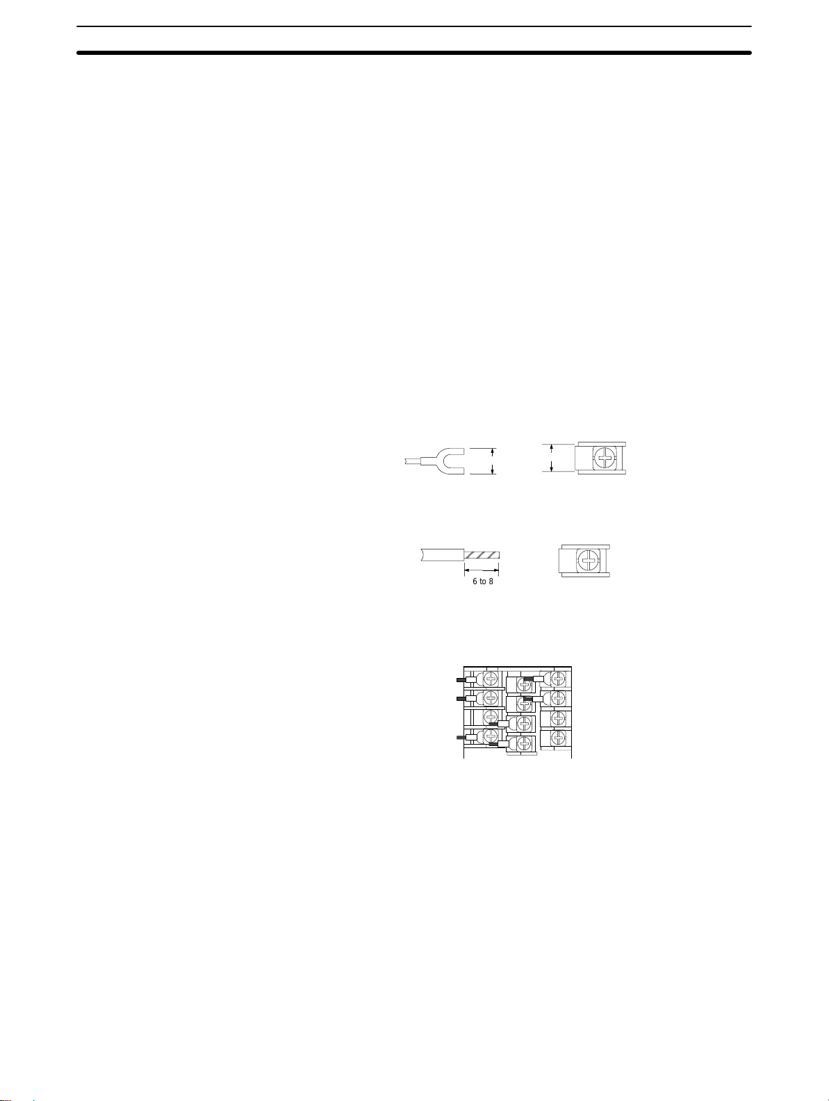
5-2-1 Connection
With Solderless Terminals Use solderless terminals for M3.5 screws. The terminal screws are M3.5 x 8 self-
up screws.
7.1 max.
Solder-dipped Leads It is possible to connect solder-dipped leads to the terminals with ease. The
length of each bare lead wire should be 6 to 8 mm.
7.3
6 to 8
For side-by-side mounting, Thermac J-series Temperature Controllers are designed so that all the lead wires can be connected to the terminals in the same
direction.
37
Page 40

Terminal Arrangement
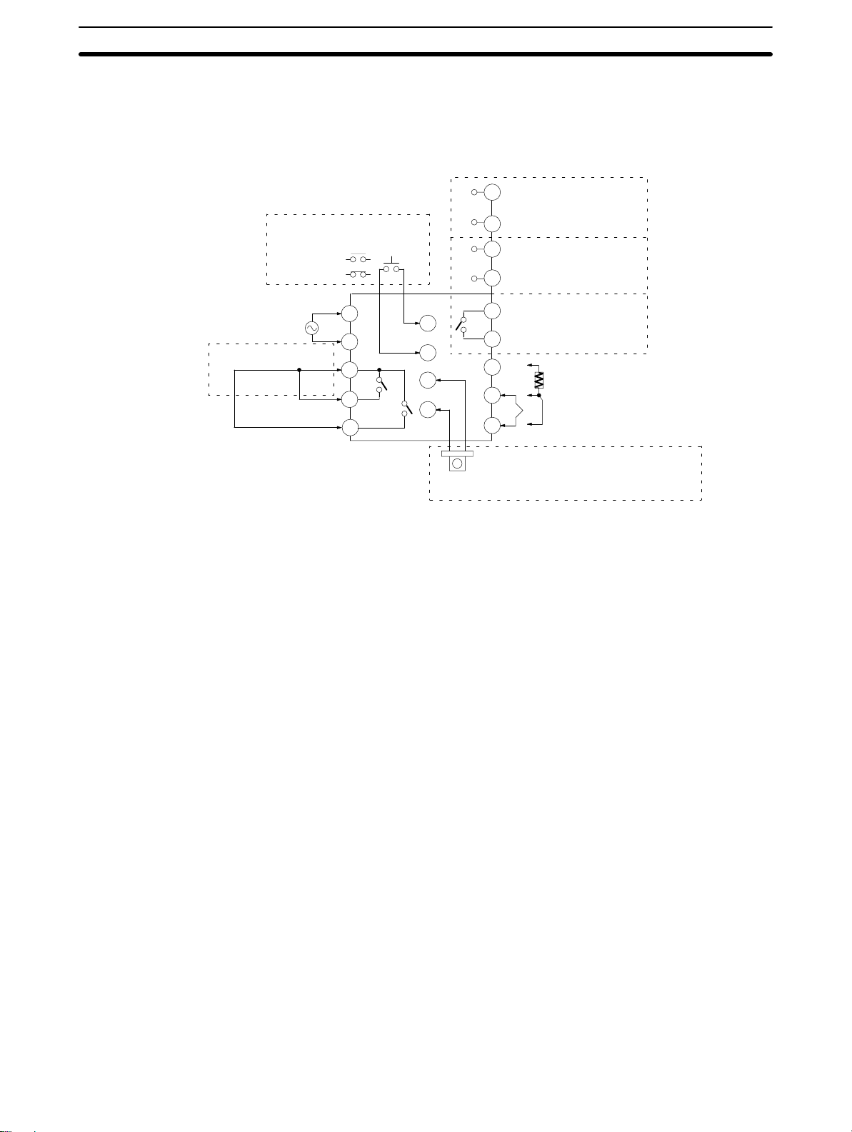
5-3 Terminal Arrangement
E5AJ/E5EJ Standard Model
Relay Output Unit
E53-R
8
250 VAC
5 A
100 to 240 VAC, 50 or 60 Hz, 14 V A
or
24 VAC, 50 or 60 Hz, 10 VA
24 VDC 6 W
Control outputSee note 1.
Alarm output 2
(ALM2)
(ALM1)
See note 3.
Alarm output 1
(Heater burnout
alarm and temperature alarm)
10
7
Current Output Unit
+53-C3
8
9
8
7
6
5
4
3
2
1
4 to 20 mA DC
7
– (600 Ω max.)
Voltage Output Unit
+E53-Q
8
12 VDC
7
– (40 mA max.)
+E53-Q3
8
– 24 VDC
7
(20 mA max.)
250 VAC
3A
250 VAC
3A
Q4
Write the name
of the Output
Unit to be used
on the nameplate on the
side of the
case.
20
29
28
27
26
25
24
23
22
21
+
19
+
18
17
–
16
15
14
13
12
11
CT
Section 5-3
See note 2.
Event input 1 (EV1)
Externally selects the set point.
Open
Short-circuit
Event input 2 (EV2)
Selects RUN or STOP.
Open
Short-circuit
A
–
B
+
B
Use the E54-CT1 with a hole diameter of
5.8 mm or E54-CT3 with a hole diameter
of 12 mm (both sold separately).
: Set point 0
: Set point 1
: RUN
: STOP
Note 1. The E53-C cannot be used.
2. The event input terminals and voltage output and current output terminals
are not insulated.
3. Only the heater burnout alarm will be output from the alarm output 1 terminals if alarm mode switch 1 is set to 0. Only the temperature alarm will be
output if the heater burnout alarm value is set to 0.0 A.
E5AJ/E5EJ with Communications Function
Relay Output Unit
8
10
7
Current Output Unit
+53-C3
8
9
8
7
6
5
4
3
2
1
4 to 20 mA DC
7
– (600 Ω max.)
Voltage Output Unit
+E53-Q
8
7
– 40 mA max.
+E53-Q3
8
– 24 VDC
7
250 VAC
3A
250 VAC
3A
100 to 240 VAC, 50 or 60 Hz, 14 V A
or
24 VAC, 50 or 60 Hz, 10 VA
24 VDC 6 W
Control outputSee note 1.
Alarm output 2
(ALM2)
(ALM1)
Alarm output 1
See note 2.
(Heater burnout
alarm and temperature alarm)
E53-R
250 VAC
5 A
12 VDC
Q4
(20 mA max.)
Write the name
of the Output
Unit to be used
on the nameplate on the side
of the case.
Communications
terminal
29
28
27
26
25
24
23
22
21
CT
Communications terminal
RS-232C RS-422 RS-485
20
RD
SG
SD
SG
29
19
28
18
27
17
26
16
25
RDB
RDA
SG
SDA
SDB
20
29
19
28
18
27
17
26
16
25
20
19
18
17
16
20
29
19
28
18
27
17
26
16
25
15
14
13
12
11
A
–
B
+
B
Use the E54-CT1 with a hole diameter of
5.8 mm or E54-CT3 with a hole diameter
of 12 mm (both sold separately).
B(+)
A(–)
SG
A(–)
B(+)
38
Note 1. The E53-C cannot be used.
Page 41
Terminal Arrangement
E5CJ Standard Model
100 to 240 VAC, 50 or 60 Hz, 12 V A
or
24 VAC, 50 or 60 HZ, 10 VA
24 VDC 6 W
See note 2.
(Heater burnout alarm
and temperature alarm)
2. Only the heater burnout alarm will be output from the alarm output 1 terminals if alarm mode switch 1 is set to 0. Only the temperature alarm will be
output if the heater burnout alarm value is set to 0.0 A.
Event input 1 (EV1) Externally selects the set point.
open
short-circuit
Alarm
output 1
Alarm output 2
1 A (resistive load)
at 250 VAC
(ALM1)
See note 1.
5
4
3
2
1
Control output (OUT)
+
10
12 VDC
–
9
+
10
–
9
14
13
12
11
+
–
CT
10
9
8
7
6
Use the E54-CT1 with a hole
diameter of 5.8 mm or E54-CT3 with a hole
diameter of 12 mm (both sold separately).
Voltage Output Unit
(20 mA max.)
Current Output Unit
4 to 20 mA DC
(with a load of 600 Ω max.)
Relay Output Unit
3 A (resistive load)
at 250 VAC
A
–
B
B
+
Section 5-3
Note 1. The event input terminals and voltage output and current output terminals
are not insulated.
2. Only the heater burnout alarm will be output from the alarm output 1 terminals if alarm mode switch 1 is set to 0. Only the temperature alarm will be
output if the heater burnout alarm value is set to 0.0 A.
3. A simple model with no alarm does not incorporate any event input or alarm
output. A simple model with an alarm function does not incorporate any
event input.
39
Page 42

This section describes the troubleshooting of the Thermac E5J Temperature Controller.
6-1 Error Display and Output 42. . . . . . . . . . . . . . . . . . . . . . . . . . . . . . . . . . . . . . . . . . . . . . . . . . .
6-2 Troubleshooting 42. . . . . . . . . . . . . . . . . . . . . . . . . . . . . . . . . . . . . . . . . . . . . . . . . . . . . . . . . .
SECTION 6
Troubleshooting
41
Page 43

Troubleshooting
6-1 Error Display and Output
The Thermac E5J Temperature Controller incorporates a self-diagnostic function. The following table lists the process values and outputs that the E5J has
when errors result.
PV display Error Output Items to be checked
Control
output
Abnormal input OFF (2 mA
max.)
Abnormal memory OFF (2 mA
max.)
Abnormal A/D
converter
OFF (2 mA
max.)
Alarm
output
Processed
as an
abnormally
high
temperature.
OFF
OFF
• Whether or not the input has exceeded the
possible controlling range (±10% of the set
temperature range) (see note).
• Whether or not the setting of the input type is
incorrect.
• Whether or not the input has been incorrectly
wired, broken, or short-circuited.
Turn the E5J OFF and ON. If the display does
not change, the E5J need repairs. If the display
returns to normal, the E5J may have been
influenced by noise. Check for noise interference.
Section 6-2
Abnormal
calibration data.
Displayed for 2 s
when the E5J is
turned on.
Normal operation (accuracy
not guaranteed)
The E5J needs calibration. Contact your
OMRON representative.
Note If the input is within the possible controlling range but exceeding the possible
display range (–1999 to 9999),
–1999 and
will be displayed if the value is larger than 9999, at which time, the
))))
(((( will be displayed if the value is smaller than
control output and alarm output will work normally.
6-2 Troubleshooting
Refer to the following table for troubleshooting.
Phenomenon Probable cause Countermeasure
Nothing is displayed when the E5J
is turned on.
No setting is possible. The key protection switch is set to ON. Set the key protection switch to OFF.
When the Up Key is pressed for set
point value setting, the value flashes
within the set temperature range and
the setting is not possible.
No alarm, heater current value display ,
or heater burnout alarm is displayed.
The internal mechanism is not
inserted properly into the housing.
The power supply is not connected to
the power supply terminals properly.
No power is supplied or the supplied
power is not within the specified
range.
The E5J with a communications
function is in remote mode.
The set point limit function is active. Properly set the set point lower limit
The alarm mode switch is set to 0. Select the proper alarm mode.
A Current Output Unit is used for
control output.
Properly insert the internal mechanism
into the housing.
Properly connect the power supply to
the power supply terminals.
Supply a voltage of 85 to 264 VAC to
the power supply terminals of the
E5J.
The E5J must be in local mode or
no front key is available.
and set point upper limit values.
No heater burnout is detected if the
Current Output Unit is used for control
output.
42
Page 44

Troubleshooting
Phenomenon CountermeasureProbable cause
The process value is abnormal or not
obtained.
No control output is obtained. No Control Output Unit is connected. Connect a Control Output Unit (sold
The heater burnout detecting function
is abnormal.
The input polarity is wrong or the
connection is wrong.
The input-type setting is incorrect. Properly set the input with the
No compensating lead wires are used
for the extension of the thermocouple.
The thermocouple and E5J is
connected via wires other than proper
lead wires.
The sensor is broken or
short-circuited.
The E5J is influenced by noise or
other induction.
°C is used instead of °F or vice versa. Use the proper temperature unit.
The process value is shifted because
the input shift function is used.
Event input 2 of the E5J is set to
STOP.
No Current Transformer (CT) is used. Properly connect the dedicated
The heater burnout alarm value is not
proper.
The heater is turned ON or OFF with
an output other than the control
output.
Properly wire the terminals.
input-type selector.
Use proper compensating lead wires.
Use a dedicated thermocouple
connector. If a metal material dif ferent
from the thermocouple is used to
connect the thermocouple and E5J,
a temperature error may result.
Use a good sensor.
Separate the input wires as far as
possible from the origin of the noise.
Set the input shift value to 0.
separately).
Open event input 2 and set the E5J
to RUN.
E54-CT1 or E54-CT3 (sold
separately) to the E5J.
Set the proper heater burnout alarm
value taking into consideration the
fluctuation of the heater supply
voltage and measurement error.
Use the control output. Heater burnout
detection synchronizes with the
control output. Any other output
cannot be used.
Section 6-2
Simple Method to Determine Temperature Controller Error or Sensor Error
When Thermocouple is Used If the temperature displayed by the E5J is close to the room temperature when
E5J is short-circuited, the E5J deemed to be normal
E5J is close to 0.0°C when a resistor with a
When Platinum Resistance
Thermometer is Used
the input terminals of the
and it is presumed that the sensor is broken, short-circuited, or incorrectly wired.
If the temperature displayed by the
resistance of approximately 100 Ω is inserted between terminals A and –B of the
E5J and terminals +B and –B of the E5J are short-circuited, the E5J
deemed to be normal and it is presumed that the sensor is broken, short-circuited, or incorrectly wired.
43
Page 45

SECTION 7
Event Input Function
This section describes how the event input function of the Thermac E5J Temperature Controller works.
7-1 Event Input Function 46. . . . . . . . . . . . . . . . . . . . . . . . . . . . . . . . . . . . . . . . . . . . . . . . . . . . . .
7-1-1 Set Point Selection 46. . . . . . . . . . . . . . . . . . . . . . . . . . . . . . . . . . . . . . . . . . . . . . . . .
7-1-2 RUN/STOP Selection (E5AJ-B, E5EJ-B) 46. . . . . . . . . . . . . . . . . . . . . . . . . . .
7-1-3 Signal Input Method 47. . . . . . . . . . . . . . . . . . . . . . . . . . . . . . . . . . . . . . . . . . . . . . .
45
Page 46

Event Input Function Section 7-1
7-1 Event Input Function
The E5J-B with an event input function is operated with ease with external
relay signal selection.
Set Point Selection It is possible to select one of the set points previously set for control operation.
RUN/STOP Selection It is possible to enable the E5AJ-B and E5EJ-B to RUN or STOP.
7-1-1 Set Point Selection
Select the set point by opening or short-circuiting event input 1 (EV1). Refer to
the following table. No set point can be selected with key operation.
EV1 Set point to be selected
Open Set point 0 (SP0)
Short-circuited Set point 1 (SP1)
The following illustration shows the operation of the E5J-B with its EV1 terminal short-circuited (i.e., set point 1 is selected).
EV1
Short-circuit
COM
Set point 0 and 1 (2 and 3) set
in advance on display level 1.
Display level 0
Displays the set point
currently selected.
Set point 0
(SP0)
Set point 1
(SP1)
Set point 2
(SP2)
Set point 3
(SP3)
SP2 and SP3 can be displayed
only when the set point selection is selected with the event
input 2 selection (set to RUN/
STOP before shipping) on the
engineering level. Refer to
tion 9 Engineering Level Settings
The set point on display level 0 and that on display level 1 are synchronized. In
the above example, if the set point on display level 0 is changed from 200°C to
250°C, the set point 1 value on display level 1 will also change to 250°C.
7-1-2 RUN/STOP Selection (E5AJ-B, E5EJ-B)
RUN or STOP operation is selected by opening or short-circuiting event input 2
(EV2). Refer to the following table. RUN or STOP operation cannot be selected
with key operation.
Sec-
for details.
46
EV2 Operation
Open RUN
Short-circuited STOP
When the E5J stops operating, its control output will be 0% and fuzzy self-tuning will stop but its alarm output will operate normally.
The operation of the E5J the moment the E5J is turned on is determined by
the condition of event input 2.
Page 47

Event Input Function Section 7-1
7-1-3 Signal Input Method
The event input terminals can be short-circuited using a relay or transistor as
shown in the following diagram.
+24 V
Signal Input Types
Internal circuitry
0 V
Contact Input No-contact Input
EV*
COM
ON: A resistance of 1 kΩ max.
OFF: A resistance of 100 kΩ min.
470 Ω
3 kΩ
VF = 1.2 VF = 0.6
(Open collector)
EV*
COM
ON: A residual voltage of 3 V max.
OFF: A current leakage of 1 mA max.
EV*
Flow current:
7 mA approx.
COM
The following table lists the event input terminal numbers for each model.
Model E5AJ/E5EJ E5CJ
Input terminal
EV1 20 14
EV2 19 --COM 17 13
47
Page 48

SECTION 8
Heater Burnout Detection
This section describes the basic features of heater burnout detection and necessary steps that should be taken at the time of
heater burnout, as well as the method of obtaining heater burnout alarm values.
8-1 Heater Burnout Detection 50. . . . . . . . . . . . . . . . . . . . . . . . . . . . . . . . . . . . . . . . . . . . . . . . . . .
8-2 Heater Burnout Procedures 50. . . . . . . . . . . . . . . . . . . . . . . . . . . . . . . . . . . . . . . . . . . . . . . . .
8-3 Wiring the Current Transformer 51. . . . . . . . . . . . . . . . . . . . . . . . . . . . . . . . . . . . . . . . . . . . . .
8-4 Heater Burnout Alarm Value 51. . . . . . . . . . . . . . . . . . . . . . . . . . . . . . . . . . . . . . . . . . . . . . . .
8-4-1 Setting Examples 52. . . . . . . . . . . . . . . . . . . . . . . . . . . . . . . . . . . . . . . . . . . . . . . . . .
49
Page 49

Heater Burnout Procedures
8-1 Heater Burnout Detection
To detect heater burnout, wire one of the lead wires for each heater through the
hole of the Current Transformer (CT). The CT generates an AC current according to the current flow of the lead wire. The Thermac E5J Temperature Controller measures the AC current to check the current flowing to the heater. If any one
of the heaters burns out, the AC current value will decrease so that the E5J
turns its heater burnout alarm ON, comparing the AC current value with the heater burnout alarm value.
8-2 Heater Burnout Procedures
The E5J starts heater burnout detection from the moment the E5J is turned
on. If any one of the heaters is turned on after the E5J is turned on, the heater
burnout alarm output will be ON because the E5J judges that the heater is
burnt out. Therefore, all the heaters must be turned on simultaneously with the
E5J or before the E5J is turned on. This is essential for smooth temperature
control and fuzzy self-tuning.
The E5J will continue temperature control even if the heater burnout alarm is
ON because the E5J will continue temperature control using the heaters that
are not burnt out.
Heater burnout detection is possible when the control output is ON. No heater
burnout detection is, however, possible if the control output is ON for less than
190 ms.
The heater burnout alarm output will be held once the heater burnout is detected. To reset the heater burnout alarm output, replace the burnout heater with
a good one and take one of the following steps.
Section 8-2
1, 2, 3...
1. Set the heater burnout alarm value to 0.0 A.
2. Turn the E5J off and on.
If the difference between the normal heater current value and heater burnout
current value is comparatively small, heater burnout detection will not be stable.
For stable detection, the difference must be 1.0 A minimum if the heater current
consumption is less than 10.0 A and 2.5 A minimum if the heater current consumption is 10.0 A or more.
Heater burnout detection is not possible if the E5J has current output, the
heater current is DC, or three-phase heaters are used.
Use the K2CU-FA-GS (with gate input terminals) for three-phase heater
burnout. Refer to the K2CU-FA-GS data sheet specifications for details.
If no heater burnout detection is executed or if no CT is used, set the heater burnout alarm value to 0.0 A. The heater burnout alarm value is factory-set to 0.0 A.
50
Page 50
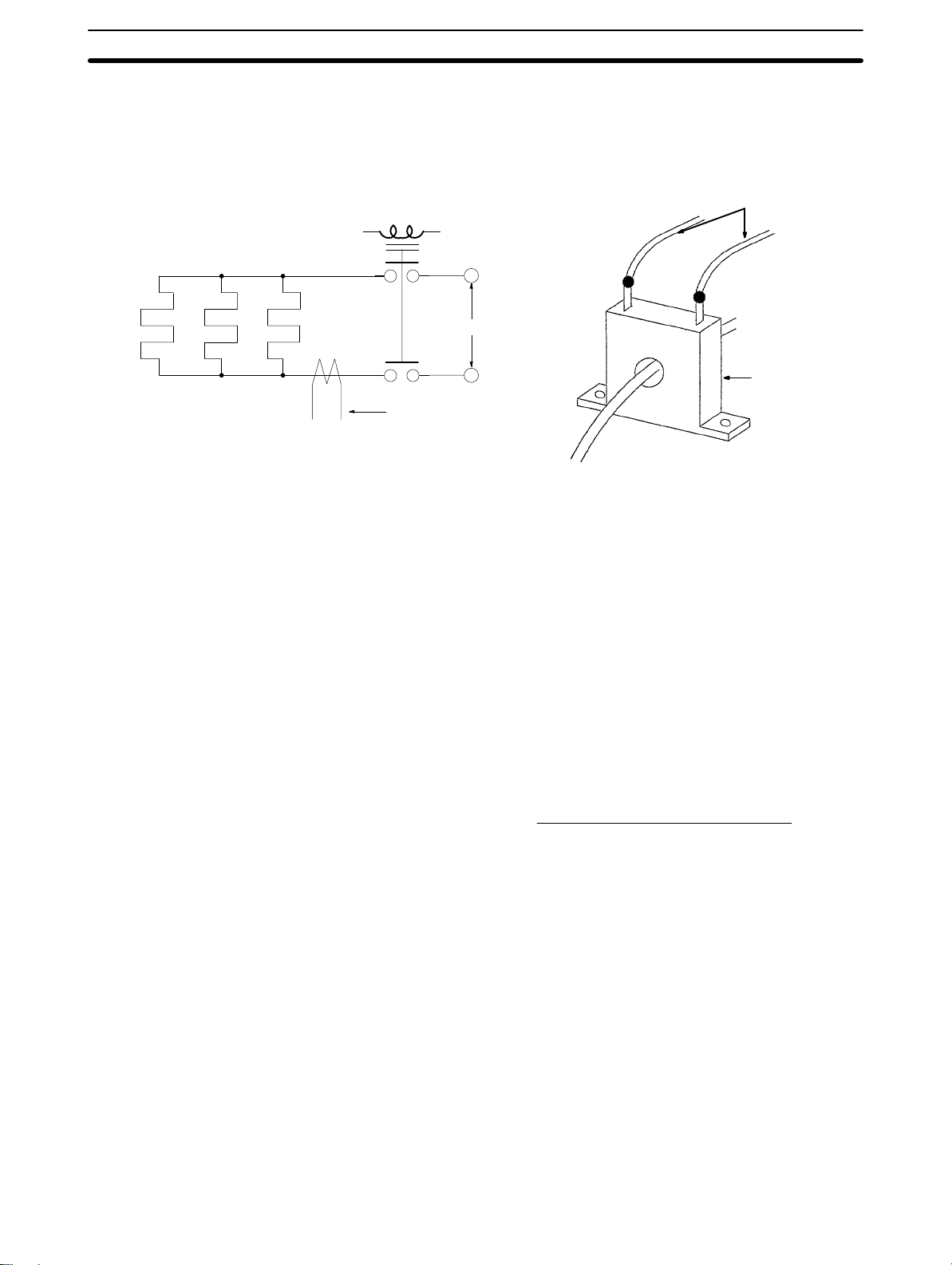
Heater Burnout Alarm Value
8-3 Wiring the Current Transformer
Refer to the following diagram for the wiring the CT.
Relay driven with
control output
Heater
Section 8-4
To the CT input terminals of the E5J.
The CT input terminals have no polarity.
AC power supply
CT
To the CT input terminals of the
E5J
8-4 Heater Burnout Alarm Value
To obtain the proper heater burnout alarm value, check the normal heater current value and heater burnout current value with the heater current value display
on display level 1 first and set the heater burnout alarm value to the mean value
of these two values. If more than one heater is used, check the burnout value of
the heater with the smallest current consumption value.
To heater
CT
Heater burnout
alarm value
Normal heater
current value
=
Heater burnout
+
current value
2
If the difference between the normal heater current value and heater burnout
current value is comparatively small, heater burnout detection will not be stable.
For stable detection, the difference must be 1.0 A minimum if the heater current
consumption is less than 10.0 A and it must be 2.5 A minimum if the heater current consumption is 10.0 A or more.
If normal current value 10.0 A
Then normal current value – heat burnout current value 1.0 A
If normal current value 10.0 A
Then normal current value – heater burnout current value 2.5 A
The heater burnout alarm value can be set within a range of 0.0 to 50.0 A. If the
alarm value is set to 0.0 A or 50.0 A, no heater burnout detection is possible. The
alarm output is always OFF if the alarm value is set to 0.0 A and always ON if th e
alarm value is set to 50.0 A.
51
Page 51

Heater Burnout Alarm Value
Section 8-4
The normal heater current value should be 50.0 A max. The heater current value
can, however, display up to 55.0 A. If the current value exceeds 55.0 A, CT input
overflow will result and ffff will be displayed.
CT input
overflow
8-4-1 Setting Examples
Example 1 In this example, 1-kW, 2-kW, and 3-kW heaters at 200 VAC are connected in par-
allel.
1, 2, 3...
1. Turn the control output ON and check the normal heater current value from
the heater current value display.
Normal current = (1000 + 2000 + 3000) 200 = 30.0 A
Heater current value display
Normal heater
current value
Heater Control
output ON
1KW 2KW 3KW
200 VAC
CT
2. Disconnect the heater whose current consumption is smallest and compare
the heater current value from the heater current value display.
Heater burnout current = 30.0 – 1000 200 25.0 A
Heater current value display
Heater burnout
current value
Heater Control
1KW 2KW 3KW
Disconnect
output ON
200 VAC
CT
Normal current – heater burnout current = 30.0 – 25.0 = 5 A ( 2.5 A)
3. Set the heater burnout alarm value to the mean value of the normal current
value and heater burnout current value.
Heater burnout alarm value = (30.0 + 25.0) 2 = 27.5 A
Example 2 In this example, 400-W, 1700-W, and 2000-W heaters at 200 VAC are con-
nected in parallel and the difference between the normal current value and heater burnout current value is less than 2.5 A.
1, 2, 3...
1. Obtain the normal current value and heater burnout current value in advance as follows:
Normal current = (400 + 1700 + 2000) 200 = 20.5 A
Heater burnout current = 20.5 – 400 200 = 18.5 A
Normal current – heater burnout current = 20.5 – 18.5 = 2.0 A (Stable detec-
tion is not possible because the value is not 2.5 A or more.)
2. For stable hater burnout detection, in such a case, increase the number of
turns of the wire passing through the CT as if apparent current value in-
52
Page 52

Heater Burnout Alarm Value
Section 8-4
creases. The displayed heater current value increases in proportion to the
number of turns of the wire passing through the CT.
Heater wire
The wire passes
through the CT
twice.
3. Obtain the heater burnout alarm value using the method in example 1.
Apparent normal current = (400 + 1700 + 2000) 200 x 2 = 41.0 A
Normal heater
current value
Apparent heater burnout current = (41.0 – 400 200) x 2 = 37.0 A
Heater burnout
current value
Normal current – heater burnout current = 41.0 – 37.0 = 4.0 A ( 2.5 A)
Heater burnout alarm value = (41.0 + 37.0) 2 = 39.0 A
Heater burnout
alarm setting
53
Page 53

SECTION 9
Engineering Level Settings
This section describes the parameters that can be changed on the engineering level. These parameters should be changed only
when the values set before shipping do not suit the application. After these parameters are changed on the engineering level,
record the contents of the changes for your future reference.
9-1 Engineering Level 56. . . . . . . . . . . . . . . . . . . . . . . . . . . . . . . . . . . . . . . . . . . . . . . . . . . . . . . .
9-2 Engineering Level Parameter List 56. . . . . . . . . . . . . . . . . . . . . . . . . . . . . . . . . . . . . . . . . . . .
9-3 Engineering Level Parameters 58. . . . . . . . . . . . . . . . . . . . . . . . . . . . . . . . . . . . . . . . . . . . . . .
55
Page 54

Engineering Level Parameter List
9-1 Engineering Level
To go to engineering level, set pin 4 of the internal function switch of the E5J to
ON before turning the E5J on. After this setting, set pin 4 of the internal function switch to OFF.
Turn on the E5J.
Set pin 4 of the
function switch to
ON.
9-2 Engineering Level Parameter List
The following is a list of engineering level parameters.
Section 9-2
This display will appear.
Display Name Setting range Setting before
shipping
d-U °C/°F selection
LEn Data bit length 7: Data length of 7 bits
PrtY Parity check
Sbit Stop bit length 1: 1 bit
S.t-b Stable range 0.1 to 999.9 °C/°F 15.0 (27.0)
15.0
ALFA Alpha 0.00 to 1.00 0.65
rEt Automatic return of
display mode
rESt Standby sequence reset
method
c: °C
f: °F
8: Data length of 8 bits
none: No parity
eUen: Even
odd: Odd
2: 2 bits
0 to 99 s
0: No automatic return
0: Reset method 0
1: Reset method 1
c
7
eUen
2
0
0
User’s remarks
56
in-S Input shift display
ALH1 Alarm 1 hysteresis 0.1 to 999.9 °C/°F 0.2 (0.4)
ALH2 Alarm 2 hysteresis 0.1 to 999.9 °C/°F 0.2 (0.4)
SL-L Set point lower limit
value
off: Not displayed
on: Displayed
Set range lower limit to
set point upper limit
value (see note 1).
(°C/°F)
off
–200 (–300)
Page 55

Engineering Level Parameter List
Section 9-2
Display User’s remarksSetting before
SL-H Set point upper limit
value
EV-2 Event input 2 type
selection
Setting rangeName
Set range lower limit
value to set range
upper limit value (see
note 1). (°C/°F)
0: Set point selection
(SP2, SP3)
1: RUN/STOP
shipping
1300 (2300)
1
Note 1. The decimal position varies with the input type.
2. The value in the parentheses is the E5J--F setting before shipping.
57
Page 56

Engineering Level Parameters
9-3 Engineering Level Parameters
15.0
Section 9-3
The value set before shipping
appears. (see note 1)
(°C/°F selection)
Displayed if the E5J with a communications function is used.
(Data bit length setting)
(Parity check setting)
(Stop bit length setting)
Displayed if the E5J is in advanced
PID operation with fuzzy self-tuning.
(Stable range setting)
Displayed if the E5J is in advanced
PID operation.
(Alpha setting)
(Automatic return of display mode)
Displayed if the E5J with an alarm
function is used (see note 2).
(Standby sequence
reset method setting)
(Input shift display selection)
Displayed if the E5J with an alarm
function is used (see note 2).
(Alarm 1 hysteresis
setting)
Displayed if the E5J with an alarm
function is used (see note 2).
(Alarm 2 hysteresis
setting)
(Set point lower limit setting)
(Set point upper limit setting)
Displayed if the E5J with
event input 2 is used.
(Event input 2 function
selection)
58
Note: 1. The E5J--F values set before shipping may be
different. Refer to
2. The value will not be displayed if the alarm mode switch is
set to 0 or if the E5J does not incorporate any alarm.
9-2 Engineering Level Parameter List.
Page 57
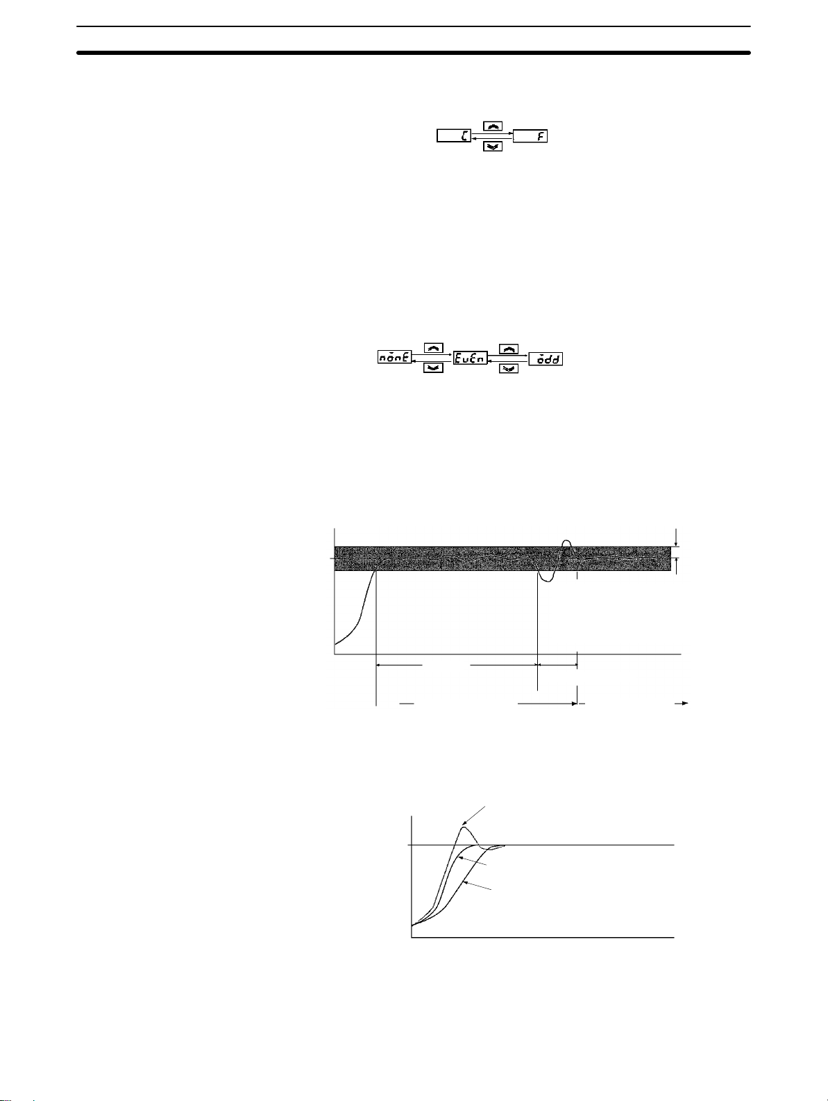
Engineering Level Parameters
Section 9-3
rdu °C/°F Selection To change the temperature display unit from °C to °F, press the Up Key so that f
will be displayed in the set value display.
E5J with
Communications Function
SV SV
The communications specifications of the E5J are as follows:
Data bit length: ASCII 7- (set before shipping) or 8-bit code
c: °C
f: °F
Parity check: None, even (set before shipping), or odd
Stop bit length: 1 or 2 (set before shipping)
Use the following parameters to change the above setting.
len Data Bit Length Use this parameter to change the communications data bit length.
prty Parity Check Use this parameter to change the communications parity check.
SV SV
SV
none : None
eUen : even
odd : odd
sbit Stop Bit Use this parameter to change the stop bit length.
s.t-b Stable Range (°C/°F) This parameter is used to decide conditions under which fuzzy self-tuning oper-
ates and can be set within a range of 0.1 to 999.9. If the absolute value of the
deviation (the difference between the process value and set point) is within the
stable range, temperature control operation is deemed smooth and fuzzy selftuning will not start.
Stable
Set point
Stable
PID before tuning
It is deemed that the characteristics
of the control device have been
changed so that the response waveform is processed to tune the PID
constants.
Fuzzy self-tuning
PID after tuning
range
alfa (α) PID Control Type By adjusting internal parameter α of advanced PID within a range of 0.00 to 1.00,
PID control such as derivative preceding PID or proportional preceding PID (IPD) control will be possible.
α = 0.00 (Derivative preceding PID)
Set point
α = 0.65
α = 1.00
(Proportional preceding PID)
Difference in set point response due to α.
To increase the set point response speed, decrease the value of parameter α. If
the value of parameter α is decreased, however, the overshooting value will increase.
59
Page 58

Engineering Level Parameters
Section 9-3
ret Automatic Return of
Display Mode (Return Time)
rest Standby Sequence
Reset Method
By setting automatic return of display mode, the display will return to the normal
operation display (on level 0 displaying the process value or set point) if no key is
operated for the time set with this parameter . The return time can be set within a
range of 0 to 99 s. If the return time is set to 0 s, this function will not work. The
return time is set to 0 s before shipping.
It is possible to select the restart conditions of the standby sequence of the alarm
attached with standby sequence. If this parameter is set to 0, the standby sequence will restart when the set point, alarm value, or input shift value is
changed or the moment the E5J starts operating including the moment the
E5J is turned on. If this parameter is set to 1, the standby sequence will restart
only the moment the E5J is turned on. The following timing chart is an example
of a lower limit alarm attached with standby sequence.
Standby sequence releasing point
Standby
sequence
releasing
OFF point due to
alarm hysteresis
Alarm point
(Standby sequence reset method 0)
Alarm output
(Standby sequence reset method 1)
Alarm output
point
Standby sequence
restart
Set value
change
ins Input Shift Display It is possible to select to display or not to display the input shift function on display
level 1 with this parameter.
alh1 Alarm 1 Hysteresis
and alh2 Alarm 2
Hysteresis
SV SV
It is possible to adjust alarm sensitivity with both these parameters within a range
of 0.1 to 999.9. Change the alarm sensitivity of the E5J if the alarm output chatters.
Upper limit alarm
ON
OFF
Low
temperature
Alarm point
Hysteresis
High
temperature
off : Not displayed
on : Displayed
Lower limit alarm
ON
OFF
Low
temperature
Hysteresis
Alarm point
High
temperature
The alarm output will be OFF when the process value is within the alarm hysteresis range when the E5J restarts (e.g., when the E5J is turned on).
sll Set Point Lower Limit
Value (°C/°F) and slh Set
Point Upper Limit Value
(°C/°F)
It is possible to limit the set point changeable range with both these parameters.
For example, if the set point lower limit value is set to 0°C and the set point upper
limit value is set to 400°C, the set point can be changed only between 0°C and
400°C.
60
Page 59

Engineering Level Parameters
Section 9-3
eu2 Event Input 2 Type
Selection
It is possible to select the function of event input 2. If 0 (set point value selection)
is selected, sp2 and sp3 will be displayed on display level 1 and if 1 is selected
RUN/STOP will be selected. When 0 is selected, the set point can be selected
from the following.
EV1
20
EV2
19
COM
17
EV1 EV2 Set point to be selected
Open Open SP0
Short-circuit Open SP1
Open Short-circuit SP2
Short-circuit Short-circuit SP3
61
Page 60

This section describes how to execute auto-tuning.
10-1 Starting Auto-tuning 64. . . . . . . . . . . . . . . . . . . . . . . . . . . . . . . . . . . . . . . . . . . . . . . . . . . . . . .
10-2 Conditions that Prevent Auto-tuning 64. . . . . . . . . . . . . . . . . . . . . . . . . . . . . . . . . . . . . . . . . .
10-3 Force-ending Auto-tuning 64. . . . . . . . . . . . . . . . . . . . . . . . . . . . . . . . . . . . . . . . . . . . . . . . . .
10-4 Changing Parameters during Auto-tuning 64. . . . . . . . . . . . . . . . . . . . . . . . . . . . . . . . . . . . . .
SECTION 10
Auto-tuning
63
Page 61

Changing Parameters during Auto-tuning
10-1 Starting Auto-tuning
Auto-tuning can be started by using the following procedure. Use this procedure
when appropriate results are not achieved via fuzzy self-tuning.
Section 10-4
1, 2, 3...
1. Turn ON pin 3 of the function selector switch to select the advanced PID control mode (refer to
2. Press the Level Key and the Display Key simultaneously for 1 s or longer to
start auto-tuning.
Section 2-3-5
).
10-2 Conditions that Prevent Auto-tuning
You will not be able to start auto-tuning when any of the following conditions exist.
• When the control mode is set for ON/OFF control or advanced PID control with
fuzzy self-tuning.
• When an engineering level parameter is displayed.
• When the key protection switch is set to SP
• When the remote/local setting is set to remote.
• When the RUN/STOP setting is set to STOP.
• When a sensor error, memory error, or A/D converter error has occurred.
10-3 Force-ending Auto-tuning
Auto-tuning will be forced to end for any of the following conditions.
• When the Temperature Controller is turned off.
• When the RUN/STOP setting is changed to STOP.
• When a sensor error occurs.
• When the Level Key and the Display Key are pressed simultaneously for 1 s or
longer.
or ALL.
10-4 Changing Parameters during Auto-tuning
• Parameters cannot be changed during auto-tuning, but the remote/local setting can be changed.
• The SP also cannot be changed via the event input during auto-tuning, but the
event input status can be changed and the SP will be changed after auto-tuning has been completed.
Auto-tuning
Open
SP0
SP0 selected.
Auto-tuning started.
Scale changes disabled here.
Shorted
SP1 selected.
Set point
Event input
terminal
64
SP1
Page 62

E5AJ
Dimensions
Appendix A
Dimensions/Mounting Holes
96 x 96
Mounting Holes
120 min.
92
12 98
112
+0.8
0
+0.8
92
0
(96 x units – 3.5)
91 x 91
+1
0
+0.8
92
0
Note 1. All dimensions shown are in millimeters.
2. Side-by-side close mounting is not possible for E5AJs equipped with the Watertight Cover (sold separately).
65
Page 63

E5EJ
Dimensions
Appendix ADimensions/Mounting Holes
48
96
Mounting Holes
120 min.
45
+0.6
0
12 98
112
+0.8
92
0
(48 x units – 2.5)
44
91
+1
0
+0.8
92
0
Note 1. All dimensions shown are in millimeters.
2. Side-by-side close mounting is not possible for E5EJs equipped with the Watertight Cover sold separately).
E5CJ
Dimensions
48 x 48
66
9.5
58
100
44.8 x 44.8
Page 64
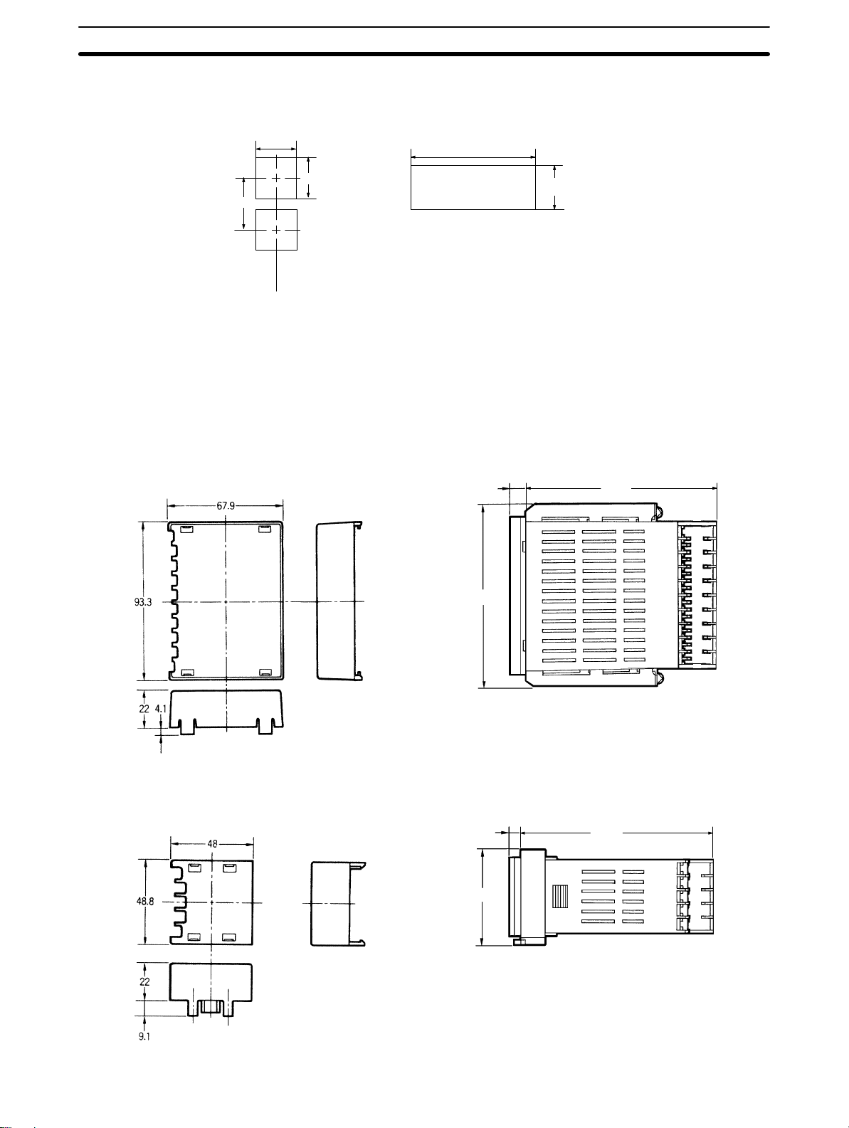
Appendix ADimensions/Mounting Holes
Mounting Holes
+0.6
45
60 min.
0
45
+0.6
0
(48 x units – 2.5)
+1
0
+0.6
45
0
Note 1. All dimensions shown are in millimeters.
2. Side-by-side close mounting is not possible for E5CJs equipped with the Watertight Cover (sold separately).
Terminal Covers
E53-COV02 E5AJ with Terminal Cover
12 115
112
E53-COV04 E5CJ with Terminal Cover
9.5
115
58
67
Page 65

E53-COV03 E5EJ with Terminal Cover
12 115
112
Appendix ADimensions/Mounting Holes
68
Page 66

Index
A
advanced PID
function, 2
setting, 14
setting with fuzzy self-tuning, 14
alarm mode
changing, 22
setting. See settings
standby sequence. See settings
auto-tuning
force-ending, 64
parameters, 64
preventing, 64
starting, 64
automatic return of display mode. See engineering level
C
communications function, specifications, 7
control period, setting range, 24
CT. See current transformer
current transformer
specifications, table, 6
wiring, 51
cycling. See hunting
D
E
engineering level
alarm hysteresis, 60
automatic return of display mode, 60
communications, 59
data bit length, 59
input shift display, 60
parameters, 19
parameters table, 56
parity check, 59
PID control type, 59
selecting temperature display, 59
settings, 56
stable range, 59
standby sequence reset, 60
stop bit, 59
event input 2, 33
selecting, 61
event input function, 2
parameters, 24
selecting RUN/STOP, 46
selecting set point, 46
signal input method, 47
external disturbance, definition, 32
F
features, 2
front panel, features, 18
functions
control mode, 14
level setting, 14
output operation, 14
selector settings, 14
fuzzy self-tuning
features, 28
function, 2
derivative time range, 25
dimensions, 65, 66, 67
display levels
level 1, 23
parameters, 22, 23
displays
engineering level, 19
levels, 19
disturbance tuning
conditions, 29
measuring external disturbance response waveform, 29
measuring set point response waveform, 29
startup conditions, 29
DT. See disturbance tuning
H
heater burnout
detection, 50
procedures, 50
heater burnout alarm
current value, 24
determining value, 51
operating characteristics, 7
parameters, 24
setting examples, 52
setting value, 24
HT. See hunting tuning
hunting, definition, 32
hunting tuning, startup conditions, 30
hysteresis, setting range, 24
69
Page 67

Index
I
installation
mounting, 36
precautions, 36
integral time range, 25
interference, definition, 33
internal switches, sensor type and control mode, 10
K-M
key protection switch, setting, 15
manual reset value, 25
models, 2
Communications Boards, 4
communications function, limitations, 3, 4
standard, 3
mounting. See installation
mounting holes, 65, 66, 67
N-O
nomenclature, 18
output unit
life expectancy, 7
npn type, 11
pnp type, 11
selecting, 10
specifications, table, 6
types and models, 2
output value, setting range, 24
set point
See also event input function
adjusting changeable range, 60
setting type, 22
settings
advanced PID control, 14
alarm mode selection, 13
functions. See functions
fuzzy self-tuning, 14
internal switches, 11, 12
key protection switch, 15
selecting input type, 12
selecting output unit, 10
sensor type and control mode, 10
specifications
general, table, 5
operating characteristics, table, 6
output unit, table, 6
SRT. See step response tuning
stability judgement time, 32
stable range, 32
stable value, 32
standby sequence, resetting. See engineering level
startup, 33
step response tuning
See also SRT
operating conditions, 28
PID constant refreshing conditions, 29
startup conditions, 28
step controlled amount, 29
STOP, selection, 46
stop bit, changing length. See engineering level
P
parameters
engineering level, 19
levels, 19
setting, 19
tables, 20
PID, setting constants, 32
proportional band range, 25
R
return time, 60
RUN, selection, 46
S
self-diagnostic function, 42
70
T
terminal arrangement, 38
Terminal Covers, 67
troubleshooting, 30
controller and sensor error, 43
table, 42
W
watertight cover, 2
wiring
current transformer, 51
precautions, 37
terminal arrangement, 38, 39
using solder-dipped leads, 37
using solderless terminals, 37
Page 68

Revision History
E5J Temperature Controller
Operation Manual
A manual revision code appears as a suffix to the catalog number on the front cover of the manual.
Cat. No. WZ103-E3-1
Revision
code
The following table outlines the changes made to the manual during each revision. Page numbers refer to the
previous version for manuals designated as E1 revisions.
Revision code Date Revised content
Z103-E1-1 November 1993 Original production
Z103-E1-1A January 1994 Page 20: Hysteresis row in the table corrected. Note added.
Page 21: Proportional band row in the table corrected. Note added.
Page 23: Proportional band setting in the diagram corrected.
Page 29: Stable range in both diagrams corrected. Note added.
Pages 30, 32: Stable range in top diagram corrected.
Page 51: “Heater current value level 1” corrected to “Heater burnout value” in
the equation.
Page 56: Stable range, alarm hysteresis 1, alarm hysteresis 2, and set point
lower limit value rows in the table corrected.
Page 57: Note added.
Z103-E1-2 March 1994 Major revision. Most of the pages have been changed or revised.
Z103-E1-3 June 1995
Z103-E1-4 November 1996 Page 2: Auto-tuning added to
Section 10 Auto-tuning
Page 2:
Page 4: Note 1 corrected.
Page 6: Models added to the Output Units table.
Page 10: Models added to the Output Units table and second sentence after
the table corrected.
Page 28: First note on the page corrected.
Page 38: The polarities for RS-485 in
tion
Page 5: Auto-tuning added to
Page 7:
ratings
Page 38: “+” added to terminals 20 and 19 and “–” added to terminal 17 in the
E5AJ/E5EJ Standard Model terminal arrangement.
Page 39: “+” added to terminal 17 and “–” added to terminal 16 in the E5BJ
terminal arrangement. “+” added to terminal 14 and “–” added to terminal 13 in
the E5CJ Standard Model terminal arrangement.
Pages 65 to 68: Terminal Covers and their dimensions added.
Output Units
.
EMC
and
changed. Notes added also.
added.
corrected.
1-1 Features
Control mode
Approved standards
E5AJ/E5EJ with Communications Func-
.
in the table.
added to the top table and
Enclosure
71
Page 69

Revision History
Revision code Revised contentDate
Z103-E1-5 February 1998 Page 4: Supply voltage and power consumption specifications changed.
Page 19: Thermac E5J information added to the beginning of
Flowchart
Pages 38, 39: Terminal arrangement diagrams changed.
Page 56: Information added to
Z103-E3-1 March 1998 All references to model E5BJ removed.
Pages 38,39: Corrected power consumption in terminal arrangement draw-
ings (based on revision E1-5); kept terminal arrangement drawings the same
as revision E1-4.
.
9-1 Engineering Level
.
3-2 Setting
72
 Loading...