

Omron E3JM-10M4T-G-N, E3JM-10M4-G-N, E3JM-10S4-G-N, E3JM-10R4-G-N, E3JM-10S4T-G-N Datasheet
...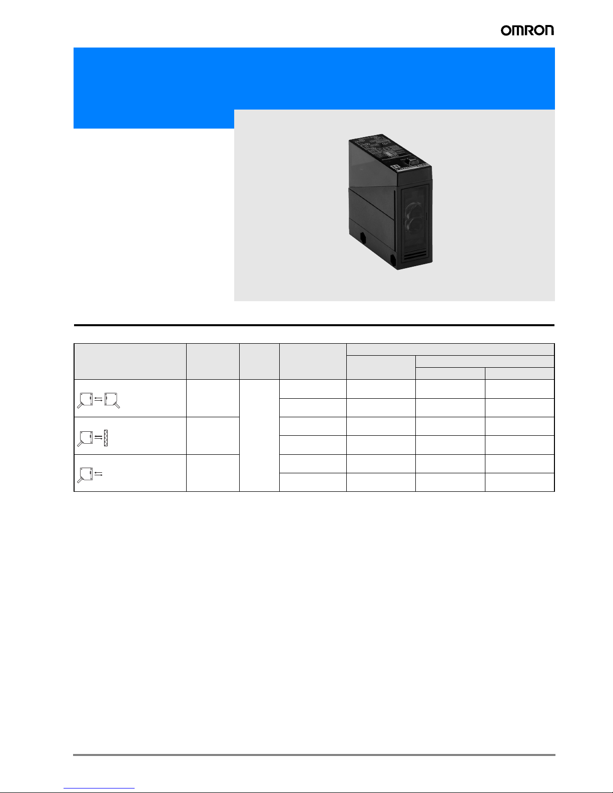
1E3JM
Multi voltage photoelectric sensor in plastic housing with timer function
E3JM
The square sized E3JM family
provides 12 to 240 VDC and 24 to
240 VAC power supply voltage, an
enhanced sensing distance and a
timer function.
• 12 to 240 VDC and 24 to 240 VAC
supply voltage
• Relay or solid state relay output
• Timer function
Ordering Information
Sensor type Sensing
distance
Connection
method
Timer function Order code
Relay output DC SSR output
minus common plus common
Through-beam 10 m Terminal
block
(with
PG 13.5)
– E3JM-10M4-G-N E3JM-10S4-G-N E3JM-10R4-G-N
ON or OFF delay
0.1 s to 5 s
E3JM-10M4T-G-N E3JM-10S4T-G-N E3JM-10R4T-G-N
Retro-reflective with M.S.R. 4 m – E3JM-R4M4-G E3JM-R4S4-G E3JM-R4R4-G
ON or OFF delay
0.1 s to 5 s
E3JM-R4M4T-G E3JM-R4S4T-G E3JM-R4R4T-G
Diffuse-reflective 700 mm
(adjustable)
– E3JM-DS70M4-G E3JM-DS70S4-G E3JM-DS70R4-G
ON or OFF delay
0.1 s to 5 s
E3JM-DS70M4T-G E3JM-DS70S4T-G E3JM-DS70R4T-G
2 Multi voltage photoelectric sensor
Accessories
Slit
Reflectors
Note 1. For the complete overview of available reflectors please refer to www.industrial.omron.eu or to the accessory datasheet E26E.
2. Values in brackets are the minimum required distance between the Sensor and Reflector.
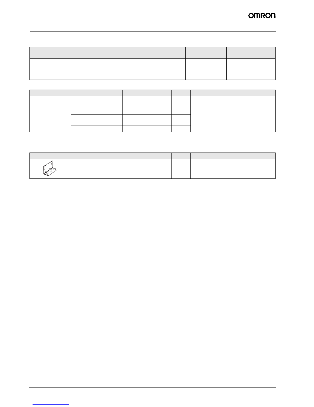
Mounting Bracket
Note: If a Through-beam Model is used, order two Mounting Brackets for the Emitter and Receiver respectively.
Slit width Sensing distance Minimum sensing
object (typical)
Model Quantity Remarks
1 mm × 20 mm 1.2 m 1 mm dia. E39-S39 1 Slit each for Emitter
and Receiver (2 Slits
total )
(Seal-type long slit)
Can be used with the
Through-beam Model
E3JM-10@4(T).
Name Sensing distance (typical) Model Quantity Remarks
Reflectors 4 m (rated value) E39-R1 1 Provided with the E3JM-R4@4(T).
Small Reflectors 3.5 m E39-R3 1 ---
Tape Reflectors 1 m (200 mm) (See note 2.) E39-RS1 1 ---
1.6 m (200 mm) (See note
2.)
E39-RS2 1
2 m (200 mm) (See note 2.) E39-RS3 1
Appearance Model Quantity Remarks
E39-L53 1 Provided with the E3JM
3E3JM
Specifications
Ratings/Characteristics
Note: The timer cannot be disabled for Models with timer functions (E3JM-@@@4T).
Item Through-beam Retro-reflective with M.S.R. Diffuse-reflective
E3JM-10@4 E3JM-10@4T E3JM-R4@4 E3JM-R4@4T E3JM-DS70@4 E3JM-
DS70@4T
Sensing distance 10 m 4 m (When using E39-R1) White paper (200 × 200 mm):
700 mm
Standard sensing object Opaque: 14.8-mm dia. min. Opaque: 75-mm dia.min. ---
Differential travel --- --- 20% max. of sensing distance
Directional angle Both Emitter and Receiver 3° to
20°
1° to 5° ---
Light source (wavelength) Infrared LED (950 nm) Red LED (660 nm) Infrared LED (950 nm)
Power supply voltage 12 to 240 VDC±10%, ripple (p-p): 10% max.
24 to 240 VAC±10%, 50/60 Hz
Power consumption 3 W max. 2 W max.
Control output Relay output (M Models): SPDT 250 VAC, 3 A max. (cosϕ = 1)
5 VDC, 10 mA min.
DC SSR output (S, R Models):48 VDC, 100 mA max. (residual voltage: 2 V max.)
Light-ON/Dark-ON selectable
Life expectancy Mechanical 50,000,000 times min. (switching frequency: 18,000 times/h)
Electrical 100,000 times min. (switching frequency: 1,800 times/h)
Response time Relay out-
put
Operation or reset: 30 ms max.
DC SSR
output
Operation or reset: 5 ms max.
Sensitivity adjustment --- One-turn adjuster
Timer function (See note.) ON-delay/OFF-delay/One-shot delay switch selectable
Delay time: 0.1 to 5 s (adjustable), only for E3JM-@@@4T
Ambient illumination (Receiver
side)
Incandescent lamp: 3,000 lx max.
Ambient temperature Operating:–25°C to 55°C (with no icing or condensation)
Storage:–30°C to 70°C (with no icing or condensation)
Ambient humidity Operating:45% to 85% (with no condensation)
Storage:35% to 95% (with no condensation)
Insulation resistance 20 MΩ min. at 500 VDC between current-carrying parts and case
Dielectric strength 2,000 VAC, 50/60 Hz for 1 min. between current-carrying parts and case
Vibration resistance
Destruction 10 to 55 Hz, 1.5-mm double amplitude for 2 hours each in X, Y, and Z directions
Malfunction 10 to 55 Hz, 1.5-mm double amplitude for 2 hours each in X, Y, and Z directions
Shock resistance Destruction 500 m/s
2
3 times each in X, Y, and Z directions
Malfunction 100 m/s
2
3 times each in X, Y, and Z directions
Degree of protection IEC 60529: IP66
Connection method Terminal block
Indicator Light indicator
(red), power indicator (red)
Operation indicator (red),
power indicator
(red)
Light indicator
(red)
Operation indicator (red)
Light indicator
(red)
Operation indicator (red)
Weight (packed state) Approx. 270 g Approx. 160 g Approx. 160 g
Material Case ABS
Lens Methacrylic resin
Cover Polycarbonate
Mounting
Bracket
Iron
Accessories Mounting Bracket (with screw), nut, terminal protection cover, one set of cable connection nuts,
reflector (E39-R1: only for retro-reflective models), instruction manual
 Loading...