

Page 1
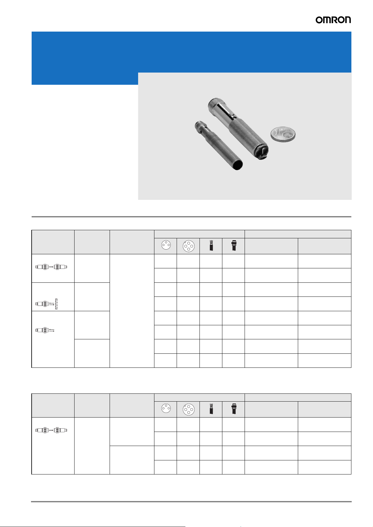
Miniature photoelectric sensors in cylindrical M8 and M12 housing
E3H2
• M8 or M12 sized cylindrical housings
when mounting space is crucial
• Retro-reflective models with two
teaching modes for standard and
semi-transparent objects
• pre-wired and connector models
Ordering Information
M12 cylindrical housing
Sensor type Sensing
distance
Through-beam 4 m
(adjustable)
Retro-reflective
with M.S.R.
Diffuse-reflective
*1.
Models without teach-button are available. Contact your OMRON representative.
*2.
Without reflector; order reflector separately
2m
(teachable
300 mm
(teachable)
100 mm
(fixed)
Operation mode Connection method Order code
light on / dark on
selectable
*1
)
––2m–
– ––
––2m–
– ––
––2m–
– ––
––2m–
– ––
M8 cylindrical housing
Sensor type Sensing
distance
Operation mode Connection method Order code
NPN output PNP output
E3H2-T4C4M 2M E3H2-T4B4M 2M
E3H2-T4C4M-M1 E3H2-T4B4M-M1
E3H2-R2C4M 2M
E3H2-R2C4M-M1
E3H2-DS30C4M 2M E3H2-DS30B4M 2M
E3H2-DS30C4M-M1 E3H2-DS30B4M-M1
E3H2-DS10C4M 2M E3H2-DS10B4M 2M
E3H2-DS10C4M-M1 E3H2-DS10B4M-M1
NPN output PNP output
*2
E3H2-R2B4M 2M
*2
E3H2-R2B4M-M1
*2
*2
Through-beam 2 m dark on
light on
––2m–
–––
––2m–
–––
E3H2-T2C2S 2M E3H2-T2B2S 2M
E3H2-T2C2S-M5 E3H2-T2B2S-M5
E3H2-T2C1S 2M E3H2-T2B1S 2M
E3H2-T2C1S-M5 E3H2-T2B1S-M5
1E3H2
Page 2
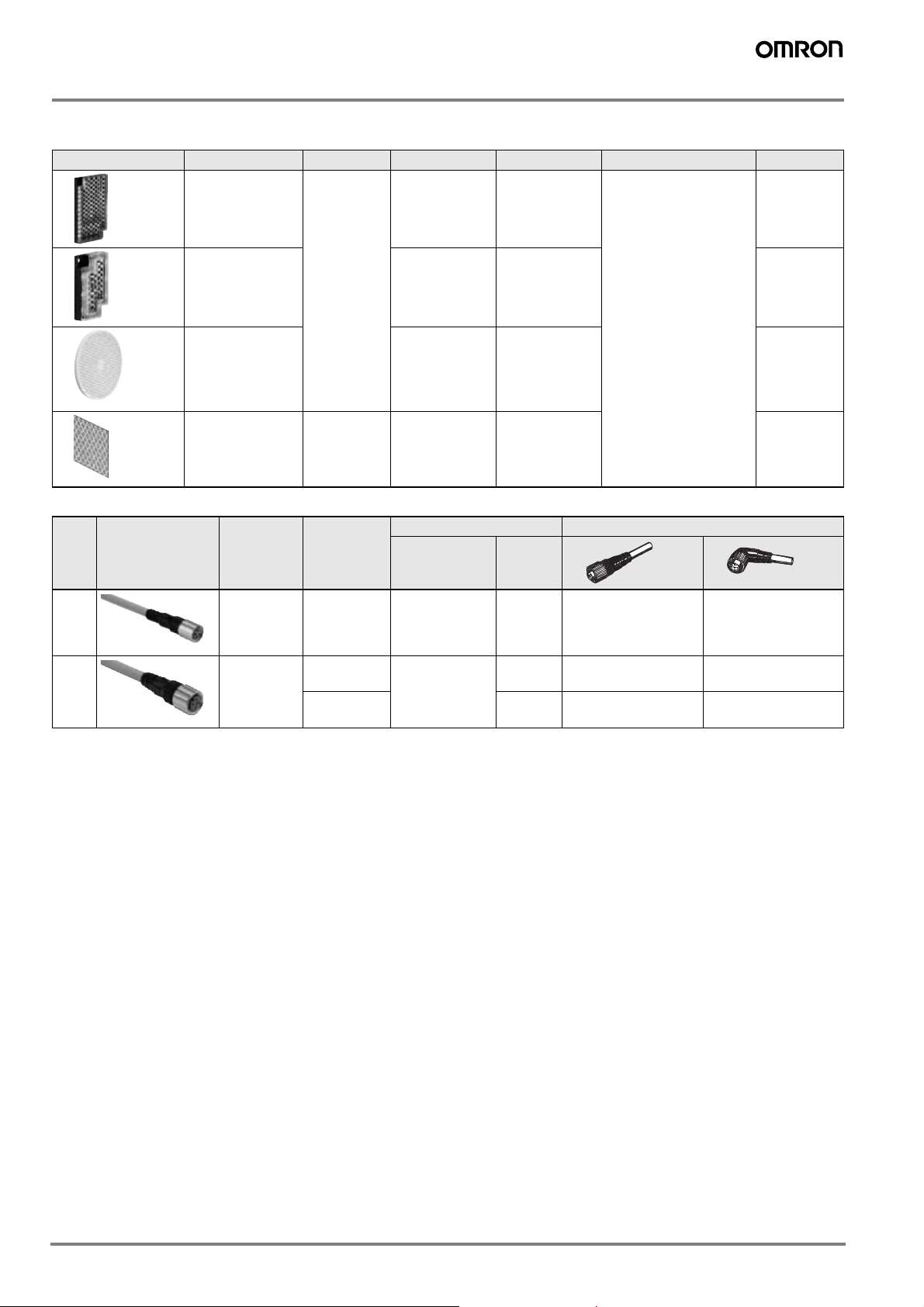
Accessories
Reflectors
Shape Type Material Features Size in mm Applicable Sensor Order code
General purpose
reflectors
Small size Surface screw
-ABS base
- Acrylic
surface
Surface screw
mounting
(diagonal holes)
mounting
60x40x7.5 - Retro-reflective photo-
electric sensors – non
polarizing
- Retro-reflective photo-
23x13.7x4.9 E39-R4
electric sensors – polarizing (MSR)
E39-R1S
Simple mounting Round shape
with centered
mounting hole
for simple screw
mounting
General purpose
tape reflectors
- Acrylic Self adhesive
Pre cut
Diameter: 84
Depth: 7.4
40x35x0.6 E39-RS2
Sensor I/O connectors
Size Shape Type Features Material Order code
Nut Cable
M8 General pur-
pose
(screw)
M12 General pur-
pose
(screw)
Note: For the complete list of sensor I/O connectors refer to E26E Accessories datasheet.
3 pin (LED
optionally)
3 wire (LED
optionally)
4 wire PVC 2 m
Brass (CuZn) PVC 2 m
PUR 2 m
Brass (CuZn) PVC 2 m
PUR 2 m
PUR 2 m
XS3F-M08PVC3S2M
XS3F-M08PUR3S2M
XS2F-M12PVC3S2M
XS2F-M12PUR3S2M
XS2F-M12PVC4S2M
XS2F-M12PUR4S2M
E39-R7
XS3F-M08PVC3A2M
XS3F-M08PUR3A2M
XS2F-M12PVC3A2M
XS2F-M12PUR3A2M
XS2F-M12PVC4A2M
XS2F-M12PUR4A2M
2 Miniature Photoelectric Sensors
Page 3

Specifications
Item Through-beam Retro-reflective with
M.S.R.
E3H2-T4 E3H2-T2 E3H2-R E3H2-DS30 E3H2-DS10
Sensing distance 4 m (adjustable) 2 m 2 m (teachable)
(when using E39R1S)
Differential travel 20% max of sensing
distance
Light source
(wave length)
Power supply
voltage
Current consumption 45 mA max
Control output Load current: 100 mA max. (residual voltage 2 V max.);
Protective circuits Power supply reverse polarity protection, output short circuit protection
Response time Operation or reset:
Sensitivity
adjustment
Ambient illumination Incandescent lamp: 1500 lx max.; Sunlight: 5000 lx max.
Ambient temperature Operating:
Degree of protection EN 60529: IP67
Indicators Emitter: Power supply indicator: yellow
Weight
pre-wired
connector
Material
case
lens
Infrared LED (880 nm) Red LED (660 nm) Infrared LED (880 nm)
10 to 30 VDC, 10% ripple
E3H2-_C_: NPN
E3H2-_B_: PNP
Light-on/dark-on
selectable by wire
2.5 ms max
Potentiometer
adjuster
-25 to +55°C
Receiver: Operation indicator: yellow
approx 110 g
approx 40 g
nickel-plated brass
plastic
10% max of sensing distance
E3H2-T2_2_: dark
on
E3H2-T2_1_: light
on
Operation or reset:
1 ms max.
–Teach-in –
Operating:
-25 to +50°C
approx 90 g
approx 30 g
stainless steel
plastic
Light-on/dark-on selectable by wire
Operation or reset: 1.1 ms max
Operating: -25 to +55°C
Output indicator: yellow
approx 55 g
approx 20 g
nickel-plated brass
plastic
Diffuse-reflective
300 mm
(teachable)
100 mm (fixed)
3E3H2
Page 4

Operation
Sensitivity adjustment
E3H2-T4
The emitter of the E3H2-T4 allows an adjustment of the emitted
amount of light by turning the potentiometer. Turn the potentiometer clockwise for increasing the amount of emitted light and
counter-clockwise for decreasing the amount of emitted light.
E3H2-R2
a) standard mode
To teach the retro-reflective model E3H2-R, place the sensor
with the lens facing the reflector. Press the teach button for 25 seconds. For remote teach connect the white wire (Pin 2) for
2-5 seconds to common (-).
The threshold is now set to 50% of the received light level.
b) high sensitivity mode (e.g. for semi-transparent models)
To teach the retro-reflective model E3H2-R in high sensitivity
mode, place the sensor with the lens facing the reflector.
Press the teach button for >8 seconds. For remote teach connect the white wire (Pin 2) for >8 seconds to common (-).
The threshold is now set just below the received light level.
If the teaching was successful the LED should no longer be flashing and a state change occurs when the light is interrupted.
E3H2-DS30
a) standard mode
To teach the diffuse-reflective model E3H2-DS30, place the
object in front of the sensor at the required sensing distance.
Press the teach button for 2-5 seconds. For remote teach
connect the white wire (Pin 2) for 2-5 seconds to common (-).
The threshold is now set to 50% of the received light level.
When the object is removed, a state change at the sensor
should occur. If this is not the case the high sensitivity mode
may be required.
b) high sensitivity mode
To teach the diffuse-reflective model E3H2-DS30 in high sen-
sitivity mode, place the object in front of the sensor at the
required sensing distance. Press the teach button for
>8 seconds. For remote teach connect the white wire (Pin 2)
for >8 seconds to common (-).
The threshold is now set just below the received light level.
When the object is removed, a state change at the sensor
should occur and the LED should no longer be flashing.
Operation mode selection
The light-on / dark-on operation mode can be selected by wire
(except for E3H2-T2). The white wire (Pin 2) can be connected to
plus (+), common (-) or left open (not connected) for the default
setting.
a) E3H2-T4 Receiver
Default setting (wire left open):DARK-ON
Connected to plus (+): LIGHT-ON
Connected to common (-): DARK-ON
b) E3H2-R2
Default setting (wire left open):DARK-ON
Connected to plus (+): LIGHT-ON
Connected to common (-): TEACH
c) E3H2-DS30
Default setting (wire left open):LIGHT-ON
Connected to plus (+): DARK-ON
Connected to common (-): TEACH
d) E3H2-DS10
Default setting (wire left open):LIGHT-ON
Connected to plus (+): DARK-ON
Connected to common (-): LIGHT-ON
For E3H2-T2 the operation mode is fixed and models with lighton and dark-on operation are available.
*1 In case the remote teach operation is required when the white wire is con-
nected to plus (+), add a 2.2 kΩ resistor between the white wire and (+)
to avoid a short circuit.
*1
*1
For E3H2-T2 and E3H2-DS10 the sensitivity setting is fixed.
4 Miniature Photoelectric Sensors
Page 5

Engineering data (typical)
Parallel operating range
Through-beam models Retroreflective models
E3H2-T4 E3H2-T2 E3H2-R2
200
100
Distance Y (mm)
0
-100
-200
012345
Distance X (m)
250
200
150
Distance Y (mm)
100
50
0
-50
-100
-150
-200
-250
0.00 0.50 1.00 1.50 2.00 2.50
Operating range
Diffuse reflective models
E3H2-DS30 E3H2-DS10
20
10
Distance Y (mm)
White paper 90%
20
Distance (mm)
10
Distance X (m)
White paper 90%
40
20
Distance Y (mm)
0
-20
-40
012
Distance X (m)
0
-10
Gray paper 18%
-20
0102030
Distance X (cm)
0
-10
-20
0246810
Gray paper 18%
Distance X (cm)
Excess gain vs. distance
Through-beam models Retroreflective Models
E3H2-T4 E3H2-T2
1000
Gain
100
10
1
0
012345
Distance (m)
100
Excess Gain
10
1
0
0,00 0,50 1,00 1,50 2,00 2,50
Distance (m)
E3H2-R2
1000
Excess Gain
100
10
1
0
012
Distance (m)
5E3H2
Page 6

Diffuse reflective Models
100
10
1
3020100
0
Distance X (cm)
Gain
White paper 90%
Gray paper 18%
1000
12
0
1
10
100
0
246810
Excess Gain
Distance (cm)
White paper 90%
Gray paper 18%
E3H2-DS30 E3H2-DS10
6 Miniature Photoelectric Sensors
Page 7

Output Circuit Diagram
PNP Output
Model Operation
mode
E3H2-T4B@
Light ON For through-
E3H2-R2B@
E3H2-D@B@
Dark ON For through-
Timing charts Mode
selector switch
beam and retro-
Light Incident
Light Interrupted
Operation indicator
(yellow)
Output transistor
Load
(e.g. relay)
Operate
ON
OFF
ON
OFF
Reset
reflective: connect the white
wire (Pin 2) to the
brown wire
(Pin 1).
For diffuse-reflective: open (do
not connect) the
white wire
(Pin 2).
beam and retro-
Light Incident
Light Interrupted
Operation indicator
(yellow)
Output transistor
Load
(e.g. relay)
Operate
ON
OFF
ON
OFF
Reset
reflective: open
(do not connect)
the white wire
(Pin 2).
For diffuse-reflective: connect
the white wire
(Pin 2) to the
brown wire (Pin
1).
Through-beam emitter
Power
indicator
(yellow)
Photoelectric
Sensor
Main
Circuit
1
3
Brown
Blue
Output circuit
Through-beam receiver, retro-reflective,
diffuse-reflective
Operation
indicator
(Yellow)
Photoelectric
Sensor
Main
Circuit
Mode Selection /
Te ac h
Connector Pin Arrangement
1
2
4
3
Connector Pin Arrangement
1
2
10 to 30 VDC
4
3
Z
(Control
output)
10 to 30 VDC
Brown
1
D
Black
4
100 mA
max.
3
Blue
2
White
Load
(Relay)
0 V
E3H2-T2B@ Light ON n.a. fixed for
Light Incident
Light Interrupted
Operation indicator
(yellow)
Output transistor
Load
(e.g. relay)
Operate
E3H2-T2B1@
ON
OFF
ON
OFF
Reset
Dark ON n.a. fixed for
Light Incident
Light Interrupted
Operation indicator
(yellow)
Output transistor
Load
(e.g. relay)
Operate
ON
OFF
ON
OFF
Reset
Through-beam emitter
Power
indicator
(yellow)
Photoelectric
Sensor
Main
Circuit
E3H2-T2B2@
Brown
1
Blue
3
Through-beam receiver
Operation
indicator
(Yellow)
Connector Pin Arrangement
Connector Pin Arrangement
10 to 30 VDC
Photoelectric
Sensor
Main
Circuit
10 to 30 VDC
Brown
1
D
Z
Black
4
(Control
output)
4
1
3
4
1
3
100 mA
max.
3
Blue
Load
(Relay)
0 V
7E3H2
Page 8

NPN Output
Light Incident
Light Interrupted
ON
OFF
ON
OFF
Operate
Reset
Operation indicator
(yellow)
Output transistor
Load
(e.g. relay)
Model Operation
mode
E3H2-T4C@
Light ON For through-
E3H2-R2C@
E3H2-D@C@
Dark ON For through-
Timing charts Mode
selector switch
Light Incident
Light Interrupted
Operation indicator
(yellow)
Output transistor
Load
(e.g. relay)
Operate
ON
OFF
ON
OFF
Reset
beam and retroreflective:
connect the
white wire (Pin 2)
to the brown wire
(Pin 1).
For diffuse-reflective:
open (do not connect) the white
wire (Pin 2).
beam and retroreflective:
open (do not connect) the white
wire (Pin 2).
For diffuse-reflective:
connect the
white wire (Pin 2)
to the brown wire
(Pin 1)
Through-beam emitter
Power
indicator
(yellow)
Photoelectric
Sensor
Main
Circuit
Output circuit
Through-beam receiver, retro-reflective,
diffuse-reflective
Operation
indicator
(Yellow)
Photoelectric
Sensor
Main
Circuit
Mode Selection /
Te ac h
Connector Pin Arrangement
1
2
3
Brown
1
10 to 30 VDC
Blue
3
Connector Pin Arrangement
4
(Control
output)
D
Z
2
Brown
1
4
Black
Blue
3
2
White
1
4
3
100 mA
max.
10 to 30 VDC
Load
(Relay)
0 V
E3H2-T2C@ Light ON n.a. - fixed for
Light Incident
Light Interrupted
Operation indicator
(yellow)
Output transistor
Load
(e.g. relay)
Operate
ON
OFF
ON
OFF
Reset
E3H2-T2C1@
Dark ON n.a. - fixed for
Light Incident
Light Interrupted
Operation indicator
(yellow)
Output transistor
Load
(e.g. relay)
Operate
Through-beam emitter
ON
OFF
ON
OFF
Reset
Power
indicator
(yellow)
Photoelectric
Sensor
Main
Circuit
E3H2-T2C2@
Brown
1
Blue
3
Through-beam receiver
Operation
indicator
(Yellow)
Photoelectric
Sensor
Main
Circuit
Connector Pin Arrangement
Connector Pin Arrangement
10 to 30 VDC
Brown
1
(Control
output)
4
Black
D
Z
Blue
3
4
1
3
4
1
3
100 mA
max.
10 to 30 VDC
Load
(Relay)
0 V
8 Miniature Photoelectric Sensors
Page 9

Dimensions
4
Ø3.75
122.34.44.4
65.5
212.3
54.5
Power inidcator (yellow)
Potentiometer
adjuster
Power inidcator (yellow)
Potentiometer
adjuster
1 38.3 8.7 6
(54)
M8x0.75
M8x1
n° 4 x Ø2
9.5
M8x0.75
49
1 42.7
Ø6.5
Ø3.1
Emitter:
power indicator (yellow)
Receiver:
operation indicator (yellow)
Emitter:
power indicator (yellow)
Receiver:
operation indicator (yellow)
4
Ø3.75
122.34.44.4
65.5
212.3
54.5
Operation inidcator (yellow)
Teach button
(E3H2-DS30 only)
Operation inidcator (yellow) Teach button (E3H2-DS30 only)
Note: All units are in millimeters unless otherwise stated.
Pre-wired models Connector models
E3H2-T4
Emitter
E3H2-T4
Receiver
E3H2-T2
Emitter/
Receiver
E3H2-R2
E3H2-D
Operation indicator (yellow) Operation indicator (yellow)
55.3
55
2.5 34 17.7
M12x1
Operation indicator (yellow) Teach button Operation indicator (yellow) Teach button
0.8
2.8
66.3
4
2.5 34 22 6.5 1
M12x1
66
M12x1
9E3H2
Page 10

Safety precautions
! Warning
This product is not designed or rated for directly or
indirectly ensuring safety of persons. Do not use it for
such a purpose.
! Caution
Do not use the product with voltage in excess of the
rated voltage. Excess voltage may result in malfunction or fire.
Never use the product with an AC power supply.
Otherwise, explosion may result.
When cleaning the product, do not apply a high-pressure spray of water to one part of the product. Otherwise, parts may become damaged and the degree of
protection may be degraded.
High-temperature environments may result in burn
injury.
Precautions for Safe Use
The following precautions must be observed to ensure safe
operation of the Sensor.
Operating Environment
Do not use the Sensor in an environment where explosive or
flammable gas is present.
Connecting Connectors
Be sure to hold the connector cover when inserting or removing
the connector. Be sure to tighten the connector lock by hand;
do not use pliers or other tools. If the tightening is insufficient, the
degree of protection will not be maintained and the Sensor may
become loose due to vibration. The appropriate tightening torque
is 0.4 to 0.5 N·m for M12 connectors and 0.3 Nm for M8 connectors.
Load
Do not use a load that exceeds the rated load.
Environements with Cleaners and Disinfectants
Do not use the Sensor in environments subject to cleaners and
disifectants. They may reduce the degree of protection.
Modifications
Do not attempt to disassemble, repair, or modify the Sensor.
Outdoor Use
Do not use the Sensor in locations subject to direct sunlight.
Cleaning
Do not use thinner, alcohol, or other organic solvents. Otherwise,
the optical properties and degree of protection may be degraded.
Surface Temperature
Burn injury may occur. The Sensor surface temperature rises depending on application conditions, such as the surrounding temperature and the power supply voltage. Use caution when
operating or washing the Sensor.
Precautions for Correct Use
Do not use the Sensor in any atmosphere or environment that
exceeds the ratings.
Do not install the Sensor in the following locations.
(1)Locations subject to direct sunlight
(2)Locations subject to condensation due to high humidity
(3)Locations subject to corrosive gas
(4)Locations where the Sensor may receive direct vibration or
shock
Connecting and Mounting
(1)The maximum power supply voltage is 30 VDC. Before turning
the power ON, make sure that the power supply voltage does
not exceed the maximum voltage.
(2)Laying Sensor wiring in the same conduit or duct as high-volt-
age wires or power lines may result in malfunction or damage
due to induction. As a general rule, wire the Sensor in a separate conduit or use shielded cable.
(3)Use an extension cable with a minimum thickness of 1 mm
and less than 100 m long.
(4)Do not pull on the cable with excessive force.
(5)Pounding the Photoelectric Sensor with a hammer or other
tool during mounting will impair water resistance.
(6)Mount the Sensor either using the bracket (sold separately) or
on a flat surface.
(7)Be sure to turn OFF the power supply before inserting or re-
moving the connector.
Cleaning
Never use thinner or other solvents. Otherwise, the Sensor surface may be dissolved.
Power Supply
If a commercial switching regulator is used, ground the FG (frame
ground) terminal.
Power Supply Reset Time
The Sensor will be able to detect objects 150 ms after the power
supply is tuned ON. Start using the Sensor 150 ms or more after
turning ON the power supply. If the load and the Sensor are connected to separate power supplies, be sure to turn ON the Sensor
first.
Turning OFF the Power Supply
Output pulses may be generated even when the power supply is
OFF. Therefore, it is recommended to first turn OFF the power
supply for the load or the load line.
Load Short-circuit Protection
This Sensor is equipped with load short-circuit protection, but be
sure to not short circuit the load. Be sure to not use an output current flow that exceeds the rated current.
Water Resistance
Do not use the Sensor in water, rainfall, or outdoors.
2
10 Miniature Photoelectric Sensors
Page 11

11E3H2
Page 12

WARRANTY
In the interest of product improvement, specifications are subject to change without notice.Cat. No. E64E-EN-01B
OMRON EUROPE B.V.
Wegalaan 67-69,
NL-2132 JD, Hoofddorp,
The Netherlands
Phone: +31 23 568 13 00
Fax: +31 23 568 13 88
www.industrial.omron.eu
OMRON’s exclusive warranty is that the products are free from defects in materials and workmanship for a period of one year (or other
period if specified) from date of sale by OMRON.
OMRON MAKES NO WARRANTY OR REPRESENTATION, EXPRESS OR IMPLIED, REGARDING NON-INFRINGEMENT, MERCHANTABILITY, OR FITNESS FOR PARTICULAR PURPOSE OF
THE PRODUCTS. ANY BUYER OR USER ACKNOWLEDGES THAT
THE BUYER OR USER ALONE HAS DETERMINED THAT THE
PRODUCTS WILL SUITABLY MEET THE REQUIREMENTS OF
THEIR INTENDED USE. OMRON DISCLAIMS ALL OTHER WARRANTIES, EXPRESS OR IMPLIED.
LIMITATIONS OF LIABILITY
OMRON SHALL NOT BE RESPONSIBLE FOR SPECIAL, INDIRECT, OR CONSEQUENTIAL DAMAGES, LOSS OF PROFITS OR
COMMERCIAL LOSS IN ANY WAY CONNECTED WITH THE
PRODUCTS, WHETHER SUCH CLAIM IS BASED ON CONTRACT,
WARRANTY, NEGLIGENCE, OR STRICT LIABILITY.
In no event shall responsibility of OMRON for any act exceed the individual price of the product on which liability is asserted.
IN NO EVENT SHALL OMRON BE RESPONSIBLE FOR WARRANTY, REPAIR, OR OTHER CLAIMS REGARDING THE PRODUCTS
UNLESS OMRON’S ANALYSIS CONFIRMS THAT THE PRODUCTS WERE PROPERLY HANDLED, STORED, INSTALLED, AND
MAINTAINED AND NOT SUBJECT TO CONTAMINATION, ABUSE,
MISUSE, OR INAPPROPRIATE MODIFICATION OR REPAIR.
SUITABILITY FOR USE
THE PRODUCTS CONTAINED IN THIS DOCUMENT ARE NOT
SAFETY RATED. THEY ARE NOT DESIGNED OR RATED FOR ENSURING SAFETY OF PERSONS, AND SHOULD NOT BE RELIED
UPON AS A SAFETY COMPONENT OR PROTECTIVE DEVICE
FOR SUCH PURPOSES. Please refer to separate catalogs for OMRON's safety rated products.
OMRON shall not be responsible for conformity with any standards,
codes, or regulations that apply to the combination of products in the
customer’s application or use of the product.
At the customer’s request, OMRON will provide applicable third party
certification documents identifying ratings and limitations of use that
apply to the products. This information by itself is not sufficient for a
complete determination of the suitability of the products in combination with the end product, machine, system, or other application or
use.
The following are some examples of applications for which particular
attention must be given. This is not intended to be an exhaustive list
of all possible uses of the products, nor is it intended to imply that the
uses listed may be suitable for the products:
• Outdoor use, uses involving potential chemical contamination or
electrical interference, or conditions or uses not described in this
document.
• Nuclear energy control systems, combustion systems, railroad sys-
tems, aviation systems, medical equipment, amusement machines,
vehicles, safety equipment, and installations subject to separate industry or government regulations.
• Systems, machines, and equipment that could present a risk to life
or property.
Please know and observe all prohibitions of use applicable to the
products.
NEVER USE THE PRODUCTS FOR AN APPLICATION INVOLVING
SERIOUS RISK TO LIFE OR PROPERTY WITHOUT ENSURING
THAT THE SYSTEM AS A WHOLE HAS BEEN DESIGNED TO
ADDRESS THE RISKS, AND THAT THE OMRON PRODUCT IS
PROPERLY RATED AND INSTALLED FOR THE INTENDED USE
WITHIN THE OVERALL EQUIPMENT OR SYSTEM.
PERFORMANCE DATA
Performance data given in this document is provided as a guide for
the user in determining suitability and does not constitute a warranty.
It may represent the result of OMRON’s test conditions, and the users
must correlate it to actual application requirements. Actual performance is subject to the OMRON Warranty and Limitations of Liability.
CHANGE IN SPECIFICATIONS
Product specifications and accessories may be changed at any time
based on improvements and other reasons.
It is our practice to change model numbers when published ratings or
features are changed, or when significant construction changes are
made. However, some specifications of the product may be changed
without any notice. When in doubt, special model numbers may be assigned to fix or establish key specifications for your application on
your request. Please consult with your OMRON representative at any
time to confirm actual specifications of purchased products.
DIMENSIONS AND WEIGHTS
Dimensions and weights are nominal and are not to be used for manufacturing purposes, even when tolerances are shown.
ERRORS AND OMISSIONS
The information in this document has been carefully checked and is
believed to be accurate; however, no responsibility is assumed for
clerical, typographical, or proofreading errors, or omissions.
PROGRAMMABLE PRODUCTS
OMRON shall not be responsible for the user’s programming of a programmable product, or any consequence thereof.
12 Miniature Photoelectric Sensors
 Loading...