

Omron E3C-LD31, E3C-LDA Series, E3C-LR11, E39-P31, E39-P41 Datasheet
...
E3C-LDA Series
A-455E3C-LDA Series
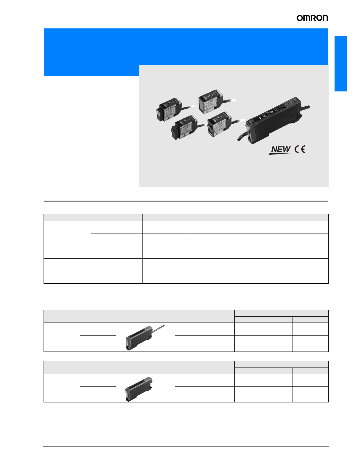
Photoelectric Sensors with Separate Digital Amplifiers (Laser-type Amplifier Units)
E3C-LDA Series
• All seven laser types provide ample
long distance, for the Diffuse Reflective
Model 1.000 mm and for Retroreflective Models up to 7.000 mm.
• Coaxial Retroreflective Models provide
detection performance equivalent to
through-beam sensors, simplifying
Sensor installation.
• Industry-first variable focal point and
optical axis alignment mechanisms.
Optimize for workpieces and improve
inspection quality.
• Drive the laser with an Amplifier the
same size as a Digital Fiber Amplifier.
Ordering Information
Sensor Heads
Note:Select a reflector (sold separately) according to the application.
Amplifier Units
Amplifier Units with Cables
Amplifier Units with Connectors
Sensing method Focus Model number Remarks
Diffuse reflective
Spot E3C-LD11
Mounting a Beam Unit (sold separately) allows the use of line and
area beams.
Line E3C-LD21
This model number is for the set consisting of the E39-P11 mount-
ed to the E3C-LD11.
Area E3C-LD31
This model number is for the set consisting of the E39-P21 mount-
ed to the E3C-LD11.
Coaxial retroreflec-
tive
Spot (variable)
E3C-LR11 (See
note.)
Mounting a Beam Unit (sold separately) allows the use of line and
area beams.
Spot (2.0-mm fixed
dia.)
E3C-LR12 (See
note.)
---
Item Appearance Functions Model
NPN output PNP output
Advanced
models
Twin-output
models
Area output, self-diagnosis, differential operation
E3C-LDA11 E3C-LDA41
External-input
models
Remote setting, counter,
differential operation
E3C-LDA21 E3C-LDA51
Item Appearance Functions Model
NPN output PNP output
Advanced
models
Twin-output
models
Area output, self-diagnosis, differential operation
E3C-LDA6 E3C-LDA8
External-input
models
Remote setting, counter,
differential operation
E3C-LDA7 E3C-LDA9
A-456 Advanced Photoelectric Sensors
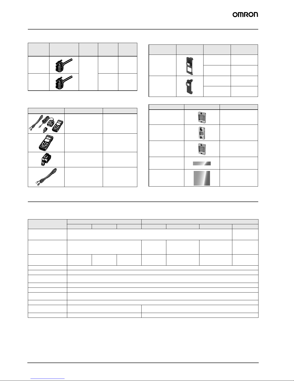
Amplifier Unit Connectors
(Order Separately)
Note:Use the E3X-MC11-S Mobile Console for the E3C-LDA series
Amplifier Units. Other Mobile Consoles cannot be used.
Mobile Console (Order Separately)
Accessories (Order Separately)
Beam Units
Reflectors
Specifications
Ratings/Characteristics
Sensor Heads
Note 1. Values are sensed for white paper.
2. These values apply when a E39-R12 Reflector is used. The MSR function is built-in. The reflected light from the object being measured
may affect the sensing accuracy, so adjust the threshold value before use.
3. The beam radius is the value for the middle measurement distance and indicates a typical value for the middle sensing distance. The radius
is defined by light intensity of 1/e
2
(13.5%) of the central light intensity.
Light will extend beyond the main beam and may be affected by conditions surrounding the object being measured.
4. The E3C-LR12 has a fixed beam size (the focus point cannot be changed).
Item Appearance Cable
length
No. of
conduc-
tors
Model
Master
Connector
2 m
4
E3X-
CN21
Slave
Connector
2
E3X-
CN22
Appearance Model Remarks
E3X-MC11-SV2-EU
E3X-MC11-SV2-UK
(model number of set)
Mobile Console with
Head, Cable, and
AC adapter provided as accessories
E3X-MC11-C1-SV2 Mobile Console
E3X-MC11-H1 Head
E39-Z12-1 Cable (1.5 m)
Applicable
Sensor Head
Appearance Focus Model
E3C-LD11
Line E39-P11
Area E39-P21
E3C-LR11
Line E39-P31
Area E39-P41
Type Appearance Model
Standard
Effective area:
23 × 23 mm
E39-R12
Standard
Effective area:
7 × 7 mm
E39-R13
Transparent
detection
Effective area:
23 × 23 mm
E39-R14
Sheet (cuttable)
Effective area:
195 × 22 mm
E39-RS4
Sheet (cuttable)
Effective area:
108 × 46 mm
E39-RS5
Item
Diffuse reflective Coaxial retroreflective
E3C-LD11 E3C-LD21 E3C-LD31 E3C-LR11 E3C-LR11 + E39-P31 E3C-LR11 + E39-P41 E3C-LR12
Light source
(emission wavelength)
Red semiconductor laser diode (650 nm), 2.5 mW max. (JIS standard: Class 2, FDA standard: Class II)
1 mW max. (JIS
standard Class
1)
Sensing distance
High-resolution mode: 30 to 1,000 mm
Standard mode: 30 to 700 mm
Super-high-speed mode: 30 to 250 mm
(See note 1.)
7 m
5 m
2 m
(See note 2.)
1,700 mm,
1,300 mm
700 mm
(See note 2.)
900 mm
700 mm
400 mm
(See note 2.)
7 m
5 m
2 m
(See note 2.)
Beam size (See note 3.)
0.8 mm max. (at
distances up to
300 mm)
33 mm (at
150 mm)
33 × 15 mm (at
150 mm)
0.8 mm max. (at
distances up to
1,000 mm)
28 mm (at 150 mm)
28 × 16 mm (at
150 mm)
2.0 mm dia. (at
distances up to
1,000 mm)
Functions Variable focal point mechanism (beam size adjustment) (See note 4.), optical axis adjustment mechanism (axis adjustment)
Indicators LDON indicator: Green; Operation indicator: Orange
Ambient illumination
(receiver side)
3,000 lx (incandescent lamp)
Ambient temperature Operating: −10° C to 55° C; Storage: −25° C to 70°C (with no icing or condensation)
Ambient humidity Operating/storage: 35% to 85% (with no condensation)
Vibration resistance
(destruction)
10 to 150 Hz with double amplitude of 0.7 mm, in X, Y, and Z directions for 80 min each
Degree of protection IEC 60529: IP40
Materials
Case and cover:ABS
Front surface filter:Acrylic resin
Case and cover:ABS
Front surface filter:Glass
Weight (packed) Approx. 85 g Approx. 100 g
A-457E3C-LDA Series
E3C-LDA Series
Amplifier Units
*1: Communications are disabled if super-high-speed mode is selected, and the mutual interference prevention function and the communications
function for the Mobile Console will not function.
*2: The preset counter is available only with advanced, external-input models.
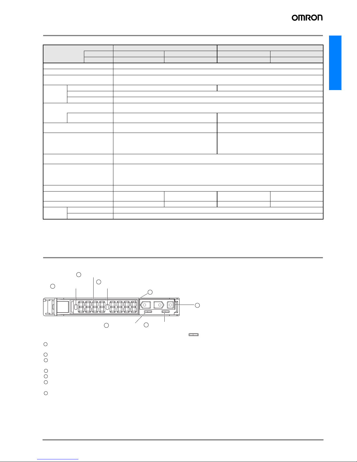
Nomenclature
Typ e Advanced, twin-output models Advanced, external-input models
Model NPN output E3C-LDA11 E3C-LDA6 E3C-LDA21 E3C-LDA7
Item PNP output E3C-LDA41 E3C-LDA8 E3C-LDA51 E3C-LDA9
Supply voltage 12 to 24 VDC ±10%, ripple (p-p) 10% max.
Power consumption 1,080 mW max. (current consumption: 45 mA max. at power supply voltage of 24 VDC)
Control output
Load power supply voltage: 26.4 VDC max.; NPN/PNP (depends on model) open collector
Load current: 50 mA max.; residual voltage: 1 V max.
Response
time
Super-high-speed mode 100 µs for operation and reset 80 µs for operation and reset
Standard mode 1 ms for operation and reset
High-resolution mode 4 ms for operation and reset
Functions
Power tuning, differential detection, timer, zero-reset, initial reset, mutual interference prevention (See note 1.), preset
counter (See note 2.), reversed display
I/O settings
Output setting (Select from channel 2 output, area output, or
self-diagnosis.)
External input setting (Select from teaching, power tuning,
zero reset, light OFF, or counter reset.)
Display
Operation indicator for channel 1 (orange), operation indica-
tor for channel 2 (orange)
Operation indicator (orange), Power Tuning indicator (orange)
Digital display
Select from the following: Incident level + threshold, incident
level percentage + threshold, incident light peak level + no incident light bottom level, minimum incident light peak level +
maximum no incident light bottom level, long bar display, incident level + peak hold, incident level + channel
Select from same displays as given at the left or a counter dis-
play.
Ambient illumination
(receiver side)
Incandescent lamp:10,000 lux max.
Sunlight:20,000 lux max.
Ambient temperature
Operating:Groups of 1 to 2 Amplifiers: −25° C to 55° C
Groups of 3 to 11 Amplifiers: −25° C to 50°C
Groups of 12 to 16 Amplifiers: −25° C to 45° C
(with no icing or condensation)
Storage: −30° C to 70° C (with no icing or condensation)
Ambient humidity Operating and storage: 35% to 85% (with no condensation)
Connection method
Prewired
cable
Separate connector
Prewired
cable
Separate connector
Weight (packed state) Approx. 100 g Approx. 55 g Approx. 100 g Approx. 55 g
Materials
Case Polybutylene terephthalate (PBT)
Cover Polycarbonate
UP
SET RUN
12
DOWN MODE
LD
1 Operation indicator
2 Main display (red)
3 Twin-output Models: Operation indicator for channel 2
External-input Models: Power tuning indicator
4 Sub-display (green)
7 Operation keys
5 SET/RUN switch
6 Twin-output Models: Channel selector
External-input Models: Operation mode selector
Lit when the output is ON.
Twin-output Models: Lit when the output for channel 1 is ON.
2 Displays the incident light level or the function name.
3 Twin-output Models: Lit when the output for channel 2 is ON.
External-input Models: Lit when power tuning is set.
4 Displays supplemental detection information, the setting of a function, etc.
5 Used to switch the mode.
6 Twin-output Models: Used to select the channel to display or set.
External-input Models: Used to select dark-ON or light-ON operation
7 Used to change the display, set functions, etc.
11
A-458 Advanced Photoelectric Sensors
Basic Operating Information
Setting the Mode
The mode is set using the SET/RUN switch. Set this switch according to the operation to be performed.
Key Operations
The operation keys are used to switch the displays and set detection conditions. The functions of the keys depend on the current
mode.
Time to Press Keys
If a specific time for pressing a key is not given in a procedure, press the key for approximately 1 second.
For example, if the procedure says “press the UP key,” then press the UP key for approximately 1 second
and then release it.
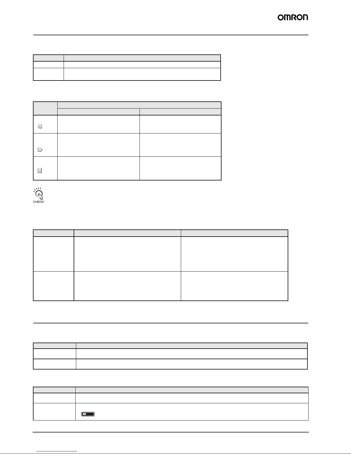
Reading Displays
The information displayed on the main display and sub-display depends on the current mode.
For the default settings, the RUN mode displays will appear when the power supply is turned ON for the first time
Note: The information that appears on the displays can be set using the display switch function. Refer to Detailed Settings.
Basic Settings
Setting the Operation Mode
Select either light-ON or dark-ON operation.
The setting method depends on the type of Amplifier Unit.
Adjusting the Power (as Required)
Mode Description
SET Select to set detection conditions, to teach the threshold value, etc.
RUN
Select for actual detection operation or to set the following: Manual adjust-
ment of thresholds, power adjustment, zero reset, or key lock.
Key
Function
RUN mode SET mode
UP key
Increases the threshold.
Depends on the setting.
− Executes teaching.
− Changes the setting forward.
DOWN
key
Decreases the threshold.
Depends on the setting.
− Executes teaching.
− Changes the setting in reverse.
MODE key
Depends on the MODE key setting.
− Executes power tuning (default setting).
− Executes a zero reset.
Switches the function to be set on the
display.
Mode Main display (red) Sub-display (green)
Set
Displays the incident light level,* function name, or
other information depending on the key operation.
*The incident light level will be displayed even if
DIFF (differential operation) is set for the detection
method.
Displays threshold value* or the setting of the func-
tion displayed on the main display depending on the
key operation.
*The threshold value for the change in the incident
light level will be displayed if DIFF (differential oper-
ation) is set for the detection method.
RUN
(See
note.)
For the default setting, the current incident light level
will be displayed.
The change in the incident light level will be dis-
played when DIFF (differential operation) is set for
the detection mode.
For the default setting, the current threshold value
will be displayed.
The threshold value for the change in the incident
light level will be displayed if DIFF (differential oper-
ation) is set for the detection method.
Selection Description
LON (light-ON)
(default)
The output will turn ON when the incident light level is above the threshold.
If DIFF (differential operation) is set for the detection method, the output will turn ON when an edge is detected.
DON (dark-ON)
The output will turn ON when the incident light level is below the threshold.
If DIFF (differential operation) is set for the detection method, the output will turn OFF when an edge is detected.
Type Setting method
Twin-output model
Set as the operation mode in SET mode.
Refer to 5. Detailed Settings.
External-input
model
Set using the operation mode selector.
LD
A-459E3C-LDA Series
E3C-LDA Series
Power tuning can be used to adjust the incident light level that is
currently being received to the power tuning target value (default: 2,000).
Before tuning ON the power, always secure the detection object and Head and be sure that the incident light level is stable.
The power tuning target value can be changed. Refer to Detailed Settings.
The incident light level may change when the detection method is changed.
If necessary, retune the power after changing the detection method.
Setting Method
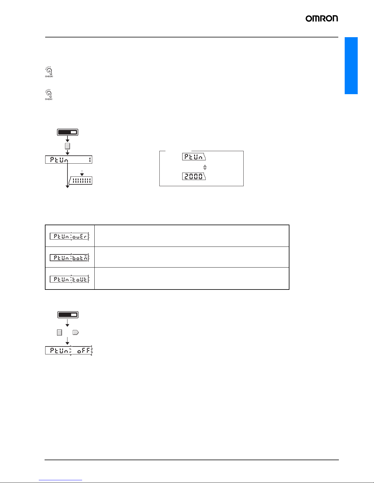
Confirm that the MODE key setting is PTUN (power tuning) in advance. PTUN is the default setting. Refer to Detailed Settings.
Setting Errors
An error has occurred if one of the following displays appears after the progress bar is displayed.
Clearing Method
Over Error
The incident light level is too low for the power tuning target value.
The power can be increased up to approximately 1.5 times the incident light level without power tuning.
Bottom Error
The incident light level is too high for the power tuning target value.
The power can be decreased down to approximately 1/8th the incident light level without power tuning.
Timeout Error
An error occurred because the incident light level was not stable during power tuning. Make sure that the work-
piece and Head are secured and retune the power.
RUNSET
Switch to RUN mode.
Tuning completed and previous display returns.
Main Display
Press the MODE key for at least 3 seconds.
Power tuning target value
PTUN
During power tuning
Progress bar
PTUN
A progress bar will appear on
the sub-display one digit at a
time.
(Release the MODE key when
the progress bar appears.)
Display alternates
at a fixed interval.
PTUN OVER
Flashes twice
PTUN BOTM
Flashes twice
PTUN TOUT
Flashes twice
Switch to RUN mode
PTUN OFF
RUNSET
Hold down the MODE key and press the DOWN key for at least 3 seconds.
Note: Press the DOWN key right after pressing the MODE key.
The sub-display will flash twice and power tuning will be cleared.
+
 Loading...