

Page 1

Cat. No. W462-E1-02
SYSMAC CP Series
CP1L-L14D#-#
CP1L-L20D#-#
CP1L-M30D#-#
CP1L-M40D#-#
CP1L CPU Unit
OPERATION MANUAL
Page 2

CP1L-L14D@-@
CP1L-L20D@-@
CP1L-M30D@-@
CP1L-M40D@-@
CP1L CPU Unit
Operation Manual
Revised June 2007
Page 3

iv
Page 4

Notice:
r
f
OMRON products are manufactured for use according to proper procedures
by a qualified operator and only for the purposes described in this manual.
The following conventions are used to indicate and classify precautions in this
manual. Always heed the information provided with them. Failure to heed precautions can result in injury to people or damage to property.
!DANGER Indicates an imminently hazardous situation which, if not avoided, will result in death or
serious injury. Additionally, there may be severe property damage.
!WARNING Indicates a potentially hazardous situation which, if not avoided, could result in death or
serious injury. Additionally, there may be severe property damage.
!Caution Indicates a potentially hazardous situation which, if not avoided, may result in minor or
moderate injury, or property damage.
OMRON Product References
All OMRON products are capitalized in this manual. The word “Unit” is also
capitalized when it refers to an OMRON product, regardless of whether or not
it appears in the proper name of the product.
The abbreviation “Ch,” which appears in some displays and on some OMRON
products, often means “word” and is abbreviated “Wd” in documentation in
this sense.
The abbreviation “PLC” means Programmable Controller. “PC” is used, however, in some CX-Programmer displays to mean Programmable Controller.
Visual Aids
OMRON, 2007
All rights reserved. No part of this publication may be reproduced, stored in a retrieval system, or transmitted, in any form, o
by any means, mechanical, electronic, photocopying, recording, or otherwise, without the prior written permission o
OMRON.
No patent liability is assumed with respect to the use of the information contained herein. Moreover, because OMRON is constantly striving to improve its high-quality products, the information contained in this manual is subject to change without
notice. Every precaution has been taken in the preparation of this manual. Nevertheless, OMRON assumes no responsibility
for errors or omissions. Neither is any liability assumed for damages resulting from the use of the information contained in
this publication.
The following headings appear in the left column of the manual to help you
locate different types of information.
Note Indicates information of particular interest for efficient and convenient opera-
tion of the product.
1,2,3... 1. Indicates lists of one sort or another, such as procedures, checklists, etc.
v
Page 5
Unit Versions of CP-series CPU Units
Unit Versions A “unit version” has been introduced to manage CPU Units in the CP Series
according to differences in functionality accompanying Unit upgrades.
Notation of Unit Versions
on Products
Confirming Unit Versions
with Support Software
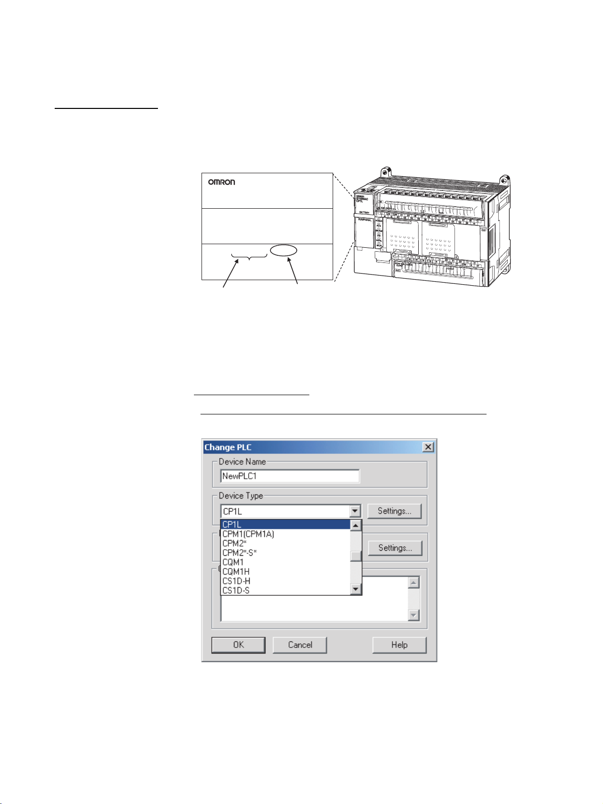
1,2,3... 1. Set the Device Type Field in the Change PLC Dialog Box to CP1L.
The unit version is given to the right of the lot number on the nameplate of the
products for which unit versions are being managed, as shown below.
Product nameplate
CPU UNIT
Lot No. 28705 0000 Ver.1.0
OMRON Corporation MADE IN CHINA
Lot No.
CP1L-M40DR-A
Unit version (Example for Unit version 1.0)
CP-series CPU Unit
CX-Programmer version 7.1 or higher can be used to confirm the unit version
of the CP1L CPU Unit.
Note CX-Programmer version 7.1 or lower cannot be used to confirm unit versions
for CP1L CPU Units.
■ Confirmation Procedure
Procedure When the Device Type and CPU Type Are Known
vi
Page 6
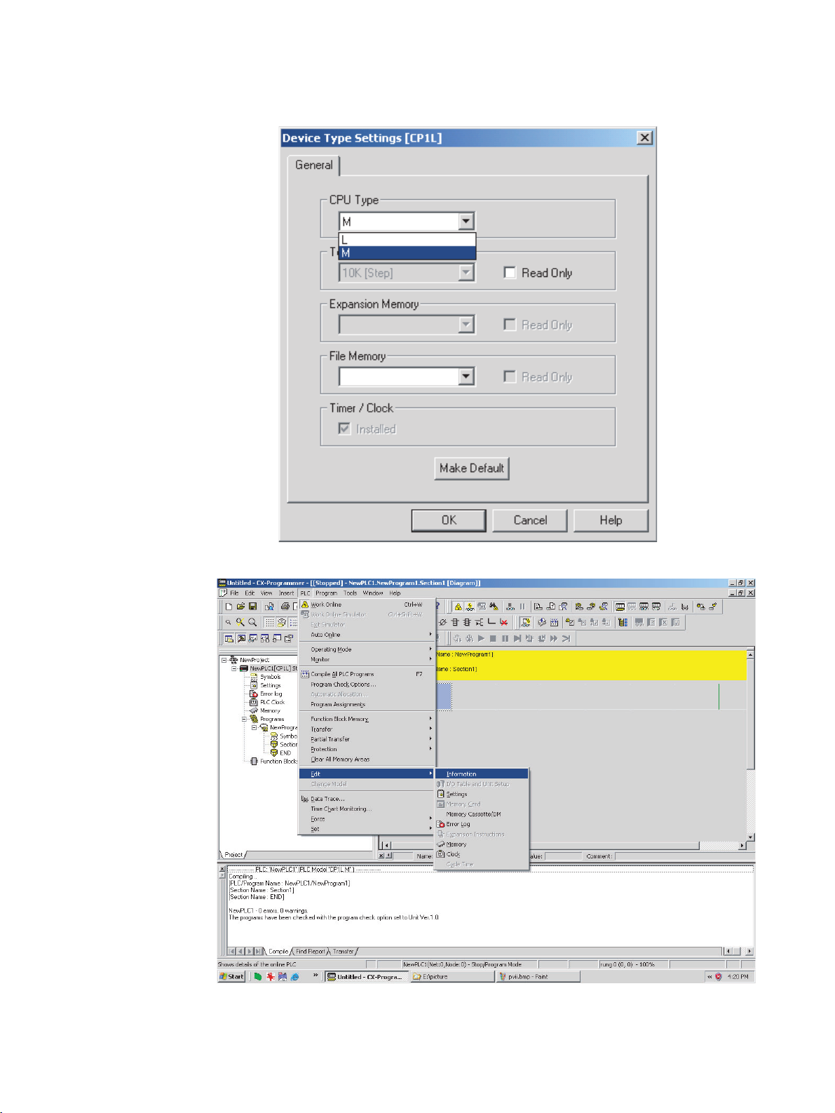
2. Click the Settings Button by the Device Type Field and, when the Device
Type Settings Dialog Box is displayed, set the CPU Type Field to M or L.
3. Go online and select PLC - Edit - Information
The PLC Information Dialog Box will be displayed.
vii
Page 7
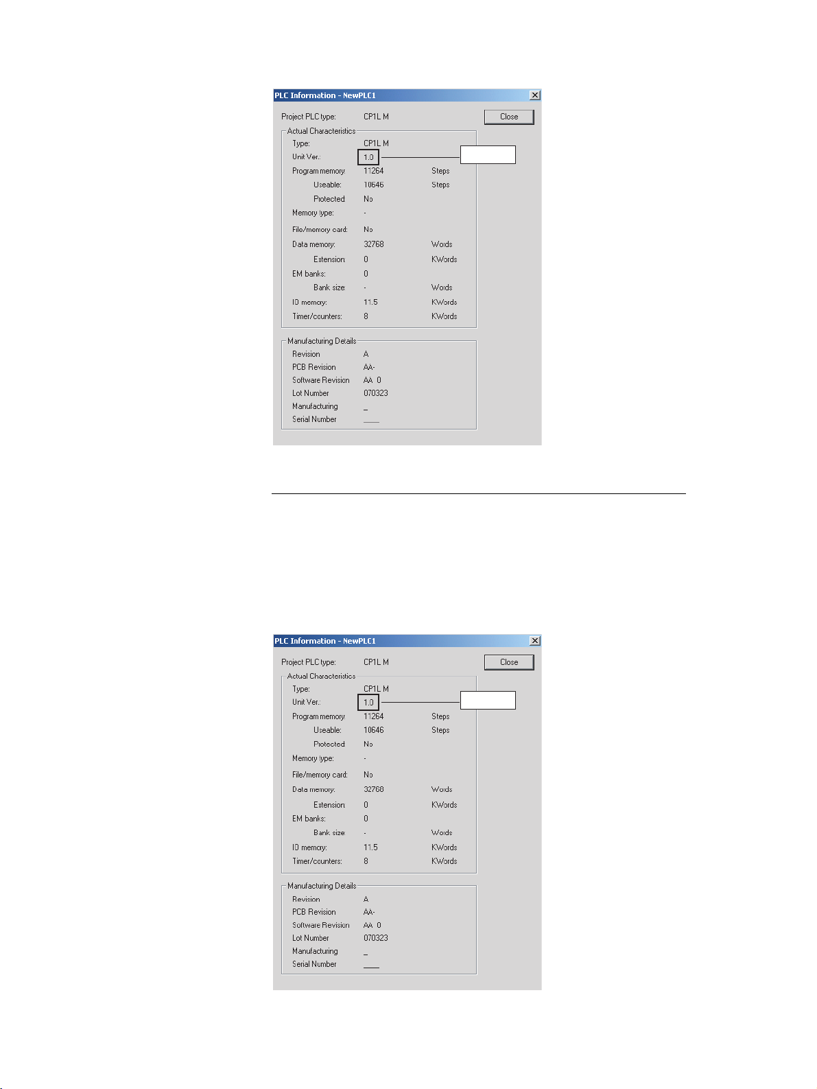
▲
Unit version
Use the above display to confirm the unit version of the CPU Unit.
Procedure When the Device Type and CPU Type Are Not Known
This procedure is possible only when connected directly to the CPU Unit with
a serial connection.
If you don't know the device type and CPU type that are connected directly to
the CPU Unit on a serial line, select PLC - Auto Online to go online, and then
select PLC - Edit - Information from the menus.
The PLC Information Dialog Box will be displayed and can be used to confirm
the unit version of the CPU Unit.
viii
▲
Unit version
Page 8
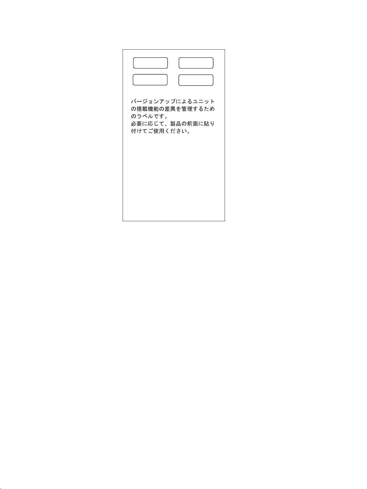
Using the Unit Version
Labels
The following unit version labels are provided with the CPU Unit.
Ver.
Ver.
Ver.
1.0
Ver.
1.0
These Labels can be used
to manage differences
in the available
functions among the Units.
Place the appropriate label
on the front of the Unit to
show what Unit
version is actually being
used.
These labels can be attached to the front of previous CPU Units to differentiate between CPU Units of different unit versions.
ix
Page 9

x
Page 10

TABLE OF CONTENTS
PRECAUTIONS . . . . . . . . . . . . . . . . . . . . . . . . . . . . . . . . . . . xxiii
1 Intended Audience. . . . . . . . . . . . . . . . . . . . . . . . . . . . . . . . . . . . . . . . . . . . . . . . . . . . . . . . . xxiv
2 General Precautions. . . . . . . . . . . . . . . . . . . . . . . . . . . . . . . . . . . . . . . . . . . . . . . . . . . . . . . . xxiv
3 Safety Precautions . . . . . . . . . . . . . . . . . . . . . . . . . . . . . . . . . . . . . . . . . . . . . . . . . . . . . . . . . xxiv
4 Operating Environment Precautions . . . . . . . . . . . . . . . . . . . . . . . . . . . . . . . . . . . . . . . . . . . xxvi
5 Application Precautions. . . . . . . . . . . . . . . . . . . . . . . . . . . . . . . . . . . . . . . . . . . . . . . . . . . . .xxvii
6 Conformance to EC Directives . . . . . . . . . . . . . . . . . . . . . . . . . . . . . . . . . . . . . . . . . . . . . . . xxx
SECTION 1
Features and System Configuration . . . . . . . . . . . . . . . . . . . 1
1-1 Features and Main Functions. . . . . . . . . . . . . . . . . . . . . . . . . . . . . . . . . . . . . . . . . . . . . . . . . 2
1-2 System Configuration . . . . . . . . . . . . . . . . . . . . . . . . . . . . . . . . . . . . . . . . . . . . . . . . . . . . . . 12
1-3 Connecting the CX-Programmer. . . . . . . . . . . . . . . . . . . . . . . . . . . . . . . . . . . . . . . . . . . . . . 20
1-4 Function Charts . . . . . . . . . . . . . . . . . . . . . . . . . . . . . . . . . . . . . . . . . . . . . . . . . . . . . . . . . . . 29
1-5 Function Blocks. . . . . . . . . . . . . . . . . . . . . . . . . . . . . . . . . . . . . . . . . . . . . . . . . . . . . . . . . . . 30
SECTION 2
Nomenclature and Specifications . . . . . . . . . . . . . . . . . . . . . 33
2-1 Part Names and Functions . . . . . . . . . . . . . . . . . . . . . . . . . . . . . . . . . . . . . . . . . . . . . . . . . . .34
2-2 Specifications. . . . . . . . . . . . . . . . . . . . . . . . . . . . . . . . . . . . . . . . . . . . . . . . . . . . . . . . . . . . . 39
2-3 CP1L CPU Unit Operation . . . . . . . . . . . . . . . . . . . . . . . . . . . . . . . . . . . . . . . . . . . . . . . . . . 63
2-4 CPU Unit Operation . . . . . . . . . . . . . . . . . . . . . . . . . . . . . . . . . . . . . . . . . . . . . . . . . . . . . . . 71
2-5 CPU Unit Operating Modes. . . . . . . . . . . . . . . . . . . . . . . . . . . . . . . . . . . . . . . . . . . . . . . . . . 75
2-6 Power OFF Operation . . . . . . . . . . . . . . . . . . . . . . . . . . . . . . . . . . . . . . . . . . . . . . . . . . . . . . 77
2-7 Computing the Cycle Time . . . . . . . . . . . . . . . . . . . . . . . . . . . . . . . . . . . . . . . . . . . . . . . . . . 79
SECTION 3
Installation and Wiring . . . . . . . . . . . . . . . . . . . . . . . . . . . . . 89
3-1 Fail-safe Circuits . . . . . . . . . . . . . . . . . . . . . . . . . . . . . . . . . . . . . . . . . . . . . . . . . . . . . . . . . . 90
3-2 Installation Precautions . . . . . . . . . . . . . . . . . . . . . . . . . . . . . . . . . . . . . . . . . . . . . . . . . . . . . 91
3-3 Mounting . . . . . . . . . . . . . . . . . . . . . . . . . . . . . . . . . . . . . . . . . . . . . . . . . . . . . . . . . . . . . . . . 93
3-4 Wiring CP1L CPU Units . . . . . . . . . . . . . . . . . . . . . . . . . . . . . . . . . . . . . . . . . . . . . . . . . . . . 99
3-5 Wiring CPU Unit I/O. . . . . . . . . . . . . . . . . . . . . . . . . . . . . . . . . . . . . . . . . . . . . . . . . . . . . . . 107
3-6 CP/CPM1A-series Expansion I/O Unit Wiring . . . . . . . . . . . . . . . . . . . . . . . . . . . . . . . . . . . 115
SECTION 4
I/O Memory Allocation . . . . . . . . . . . . . . . . . . . . . . . . . . . . . 121
4-1 Overview of I/O Memory Area . . . . . . . . . . . . . . . . . . . . . . . . . . . . . . . . . . . . . . . . . . . . . . . 122
4-2 I/O Area and I/O Allocations. . . . . . . . . . . . . . . . . . . . . . . . . . . . . . . . . . . . . . . . . . . . . . . . .129
4-3 1:1 Link Area. . . . . . . . . . . . . . . . . . . . . . . . . . . . . . . . . . . . . . . . . . . . . . . . . . . . . . . . . . . . . 135
4-4 Serial PLC Link Area . . . . . . . . . . . . . . . . . . . . . . . . . . . . . . . . . . . . . . . . . . . . . . . . . . . . . . 136
xi
Page 11

TABLE OF CONTENTS
4-5 Internal Work Area . . . . . . . . . . . . . . . . . . . . . . . . . . . . . . . . . . . . . . . . . . . . . . . . . . . . . . . . 136
4-6 Holding Area (H). . . . . . . . . . . . . . . . . . . . . . . . . . . . . . . . . . . . . . . . . . . . . . . . . . . . . . . . . . 137
4-7 Auxiliary Area (A). . . . . . . . . . . . . . . . . . . . . . . . . . . . . . . . . . . . . . . . . . . . . . . . . . . . . . . . . 138
4-8 TR (Temporary Relay) Area . . . . . . . . . . . . . . . . . . . . . . . . . . . . . . . . . . . . . . . . . . . . . . . . . 138
4-9 Timers and Counters . . . . . . . . . . . . . . . . . . . . . . . . . . . . . . . . . . . . . . . . . . . . . . . . . . . . . . . 139
4-10 Data Memory Area (D) . . . . . . . . . . . . . . . . . . . . . . . . . . . . . . . . . . . . . . . . . . . . . . . . . . . . . 143
4-11 Index Registers . . . . . . . . . . . . . . . . . . . . . . . . . . . . . . . . . . . . . . . . . . . . . . . . . . . . . . . . . . . 144
4-12 Data Registers . . . . . . . . . . . . . . . . . . . . . . . . . . . . . . . . . . . . . . . . . . . . . . . . . . . . . . . . . . . . 151
4-13 Task Flags . . . . . . . . . . . . . . . . . . . . . . . . . . . . . . . . . . . . . . . . . . . . . . . . . . . . . . . . . . . . . . . 153
4-14 Condition Flags . . . . . . . . . . . . . . . . . . . . . . . . . . . . . . . . . . . . . . . . . . . . . . . . . . . . . . . . . . . 153
4-15 Clock Pulses . . . . . . . . . . . . . . . . . . . . . . . . . . . . . . . . . . . . . . . . . . . . . . . . . . . . . . . . . . . . . 155
SECTION 5
Pulse and Counter Functions. . . . . . . . . . . . . . . . . . . . . . . . . 157
5-1 High-speed Counters . . . . . . . . . . . . . . . . . . . . . . . . . . . . . . . . . . . . . . . . . . . . . . . . . . . . . . . 158
5-2 Pulse Outputs. . . . . . . . . . . . . . . . . . . . . . . . . . . . . . . . . . . . . . . . . . . . . . . . . . . . . . . . . . . . . 177
5-3 Inverter Positioning . . . . . . . . . . . . . . . . . . . . . . . . . . . . . . . . . . . . . . . . . . . . . . . . . . . . . . . . 260
SECTION 6
Advanced Functions . . . . . . . . . . . . . . . . . . . . . . . . . . . . . . . . 317
6-1 Interrupt Functions. . . . . . . . . . . . . . . . . . . . . . . . . . . . . . . . . . . . . . . . . . . . . . . . . . . . . . . . . 318
6-2 Quick-response Inputs . . . . . . . . . . . . . . . . . . . . . . . . . . . . . . . . . . . . . . . . . . . . . . . . . . . . . . 340
6-3 Serial Communications . . . . . . . . . . . . . . . . . . . . . . . . . . . . . . . . . . . . . . . . . . . . . . . . . . . . . 344
6-4 Analog Adjuster and External Analog Setting Input. . . . . . . . . . . . . . . . . . . . . . . . . . . . . . . 371
6-5 Battery-free Operation. . . . . . . . . . . . . . . . . . . . . . . . . . . . . . . . . . . . . . . . . . . . . . . . . . . . . . 372
6-6 Memory Cassette Functions . . . . . . . . . . . . . . . . . . . . . . . . . . . . . . . . . . . . . . . . . . . . . . . . . 374
6-7 Program Protection . . . . . . . . . . . . . . . . . . . . . . . . . . . . . . . . . . . . . . . . . . . . . . . . . . . . . . . . 382
6-8 Failure Diagnosis Functions . . . . . . . . . . . . . . . . . . . . . . . . . . . . . . . . . . . . . . . . . . . . . . . . .391
6-9 Clock . . . . . . . . . . . . . . . . . . . . . . . . . . . . . . . . . . . . . . . . . . . . . . . . . . . . . . . . . . . . . . . . . . . 395
SECTION 7
Using Expansion Units and Expansion I/O Units . . . . . . . . 397
7-1 Connecting Expansion Units and Expansion I/O Units. . . . . . . . . . . . . . . . . . . . . . . . . . . . . 398
7-2 Analog Input Units . . . . . . . . . . . . . . . . . . . . . . . . . . . . . . . . . . . . . . . . . . . . . . . . . . . . . . . . 399
7-3 Analog Output Units . . . . . . . . . . . . . . . . . . . . . . . . . . . . . . . . . . . . . . . . . . . . . . . . . . . . . . . 408
7-4 Analog I/O Units . . . . . . . . . . . . . . . . . . . . . . . . . . . . . . . . . . . . . . . . . . . . . . . . . . . . . . . . . . 416
7-5 Temperature Sensor Units . . . . . . . . . . . . . . . . . . . . . . . . . . . . . . . . . . . . . . . . . . . . . . . . . . .439
7-6 CompoBus/S I/O Link Units . . . . . . . . . . . . . . . . . . . . . . . . . . . . . . . . . . . . . . . . . . . . . . . . . 454
7-7 DeviceNet I/O Link Units . . . . . . . . . . . . . . . . . . . . . . . . . . . . . . . . . . . . . . . . . . . . . . . . . . .460
xii
Page 12

TABLE OF CONTENTS
SECTION 8
Program Transfer, Trial Operation, and Debugging . . . . . 467
8-1 Program Transfer . . . . . . . . . . . . . . . . . . . . . . . . . . . . . . . . . . . . . . . . . . . . . . . . . . . . . . . . . . 468
8-2 Trial Operation and Debugging . . . . . . . . . . . . . . . . . . . . . . . . . . . . . . . . . . . . . . . . . . . . . . . 468
SECTION 9
Troubleshooting . . . . . . . . . . . . . . . . . . . . . . . . . . . . . . . . . . . 475
9-1 Error Classification and Confirmation. . . . . . . . . . . . . . . . . . . . . . . . . . . . . . . . . . . . . . . . . . 476
9-2 Troubleshooting. . . . . . . . . . . . . . . . . . . . . . . . . . . . . . . . . . . . . . . . . . . . . . . . . . . . . . . . . . . 478
9-3 Error Log . . . . . . . . . . . . . . . . . . . . . . . . . . . . . . . . . . . . . . . . . . . . . . . . . . . . . . . . . . . . . . . . 487
9-4 Troubleshooting Unit Errors . . . . . . . . . . . . . . . . . . . . . . . . . . . . . . . . . . . . . . . . . . . . . . . . .488
SECTION 10
Inspection and Maintenance . . . . . . . . . . . . . . . . . . . . . . . . . 491
10-1 Inspections . . . . . . . . . . . . . . . . . . . . . . . . . . . . . . . . . . . . . . . . . . . . . . . . . . . . . . . . . . . . . . . 492
10-2 Replacing User-serviceable Parts . . . . . . . . . . . . . . . . . . . . . . . . . . . . . . . . . . . . . . . . . . . . . 494
Appendices
A Standard Models . . . . . . . . . . . . . . . . . . . . . . . . . . . . . . . . . . . . . . . . . . . . . . . . . . . . . . . . . . 499
B Dimensions Diagrams . . . . . . . . . . . . . . . . . . . . . . . . . . . . . . . . . . . . . . . . . . . . . . . . . . . . . .503
C Auxiliary Area Allocations by Function . . . . . . . . . . . . . . . . . . . . . . . . . . . . . . . . . . . . . . . . 509
D Auxiliary Area Allocations by Address . . . . . . . . . . . . . . . . . . . . . . . . . . . . . . . . . . . . . . . . 531
E Memory Map . . . . . . . . . . . . . . . . . . . . . . . . . . . . . . . . . . . . . . . . . . . . . . . . . . . . . . . . . . . . 579
F Connections to Serial Communications Option Boards . . . . . . . . . . . . . . . . . . . . . . . . . . . . 581
G PLC Setup . . . . . . . . . . . . . . . . . . . . . . . . . . . . . . . . . . . . . . . . . . . . . . . . . . . . . . . . . . . . . . . 607
Index. . . . . . . . . . . . . . . . . . . . . . . . . . . . . . . . . . . . . . . . . . . . . 631
Revision History . . . . . . . . . . . . . . . . . . . . . . . . . . . . . . . . . . . 637
xiii
Page 13

TABLE OF CONTENTS
xiv
Page 14
About this Manual:
This manual describes installation and operation of the CP-series Programmable Controllers (PLCs)
and includes the sections described below. The CP Series provides advanced package-type PLCs
based on OMRON’s advanced control technologies and vast experience in automated control.
Please read this manual carefully and be sure you understand the information provided before
attempting to install or operate a CP-series PLC. Be sure to read the precautions provided in the following section.
Definition of the CP Series
The CP Series is centered around the CP1H and CP1L CPU Units and is designed with the same
basic architecture as the CS and CJ Series. Always use CP-series Expansion Units and CP-series
Expansion I/O Units when expanding I/O capacity.
I/O words are allocated in the same way as the CPM1A/CPM2A PLCs, i.e., using fixed areas for inputs
and outputs.
CS Series CJ Series CP Series
CS/CJ/CP Series
CS1-H CPU Units
CS1H-CPU@@H
CS1G-CPU@@H
CS1 CPU Units
CS1H-CPU@@ (-V1)
CS1G-CPU@@ (-V1)
CS1D CPU Units
CS1D CPU Units for
Duplex-CPU System
@@H
CS1D-CPU
CS1D CPU Units for
Single-CPU System
@@
CS1D-CPU S
CS1D Process CPU Units
@@P
CS1D-CPU
CS-series Basic I/O Units
CS-series Special I/O Units
CS-series CPU Bus Units
CS-series Power Supply Units
Note: Products specifically for the CS1D
Series are required to use CS1D
CPU Units.
CJ1-H CPU Units
CJ1H-CPU@@H
CJ1G-CPU@@H
CJ1G -CPU@@P
(Loop CPU Unit)
CJ1M CPU Unit
CJ1M-CPU@@
CJ1 CPU Unit
CJ1G-CPU@@
CJ-series Basic I/O Units
CJ-series Special I/O Units
CJ-series CPU Bus Units
CJ-series Power Supply Units
CP1H CPU Unit
CP1H-X40D@-@
CP1H-XA40D@-@
CP1H-Y20DT-D
CPM1A-series Expansion I/O Units
CPM1A-series Expansion Units
CP-series Expansion I/O Units
CP-series Expansion Units
CJ-series Special I/O Units
CJ-series CPU Bus Units
CP1L CPU Unit
CP1L-L14D@-@
CP1L-L20D@-@
CP1L-M30D@-@
CP1L-M40D@-@
CP/CPM1A-series Expansion I/O Units
CP/CPM1A-series Expansion Units
xv
Page 15

Precautions provides general precautions for using the Programmable Controller and related devices.
Section 1 introduces the features of the CP1L and describes its configuration. It also describes the
Units that are available and connection methods for Programming Devices and other peripheral
devices.
Section 2 describes the names and functions of CP1L parts and provides CP1L specifications.
Section 3 describes how to install and wire the CP1L.
Section 4 describes the structure and functions of the I/O Memory Areas and Parameter Areas.
Section 5 describes the CP1L’s interrupt and high-speed counter functions.
Section 6 describes all of the advanced functions of the CP1L that can be used to achieve specific
application needs.
Section 7 describes how to use CP-series Expansion Units and Expansion I/O Units
Section 8 describes the processes used to transfer the program to the CPU Unit and the functions that
can be used to test and debug the program.
Section 9 provides information on hardware and software errors that occur during CP1L operation
Section 10 provides inspection and maintenance information.
The Appendices provide product lists, dimensions, tables of Auxiliary Area allocations, and a memory
map.
xvi
Page 16

Related Manuals
The following manuals are used for the CP1L CPU Units. Refer to these manuals as required.
Cat. No. Model numbers Manual name Description
W462 CP1L-L14D@-@
CP1L-L20D@-@
CP1L-M30D@-@
CP1L-M40D@-@
W451 CP1H-X40D@-@
CP1H-XA40D@-@
CP1H-Y20DT-D
CP1L-L14D@-@
CP1L-L20D@-@
CP1L-M30D@-@
CP1L-M40D@-@
W461 CP1L-L14D@-@
CP1L-L20D@-@
CP1L-M30D@-@
CP1L-M40D@-@
W446 WS02-CXPC1-E-V70 SYSMAC CX-Pro-
W447 WS02-CXPC1-E-V70 SYSMAC CX-Pro-
W463 CXONE-AL@@C-EV2
CXONE-AL@@D-EV2
W464 CX-Integrator Opera-
SYSMAC CP Series
CP1L CPU Unit Operation Manual
SYSMAC CP Series
CP1H /CP1L CPU
Unit Programming
Manual
SYSMAC CP Series
CP1L CPU Unit Introduction Manual
grammer
Ver. 7.1 Operation
Manual
grammer Ver. 7.1
Operation Manual
Function Blocks
CX-One Setup Manual
tion Manual
Provides the following information on the CP Series:
• Overview, design, installation, maintenance, and
other basic specifications
•Features
• System configuration
• Mounting and wiring
• I/O memory allocation
• Troubleshooting
Use this manual together with the CP1L Program-
mable Controllers Programming Manual (W451).
Provides the following information on programming
the CP Series:
• Programming methods
•Tasks
• Programming instructions
Describes basic setup methods of CP1L PLCs:
• Basic configuration and component names
• Mounting and wiring
• Programming, data transfer, and debugging using
the CX-Programmer
• Application program examples
Provides information on installing and operating the
CX-Programmer for all functions except for function
blocks.
Provides specifications and operating procedures
for function blocks. Function blocks can be used
with CX-Programmer Ver. 7.1 or higher and a CP1L
CPU Unit. Refer to W446 for operating procedures
for functions other than function blocks.
Provides an overview of and describes how to
install the CX-One FA Integrated Tool Package.
Describes operating the CX-Integrator, including
operations to build networks (e.g., setting data links,
routing tables, and Communications Units.
xvii
Page 17

Cat. No. Model numbers Manual name Description
W344 WS02-PSTC1-E CX-Protocol Opera-
W342 CS1G/H-CPU@@H
CS1G/H-CPU@@-V1
CS1D-CPU@@H
CS1D-CPU@@S
CS1W-SCU@@-V1
CS1W-SCB@@-V1
CJ1G/H-CPU@@H
CJ1G-CPU@@P
CJ1M-CPU@@
CJ1G-CPU@@
CJ1W-SCU@@-V1
tion Manual
SYSMAC CS/CJ/CP/
NSJ-series Communications Commands
Reference Manual
Provides operating procedures for creating protocol
macros (i.e., communications sequences) with the
CX-Protocol and other information on protocol macros.
The CX-Protocol is required to create protocol macros for user-specific serial communications or to
customize the standard system protocols.
Describes commands addressed to CS-series, CJseries, and CP-series CPU Units, including C-mode
commands and FINS commands.
Note This manual describes on commands
address to CPU Units regardless of the communications path. (CPU Unit serial ports,
Serial Communications Unit/Board ports, and
Communications Unit ports can be used.)
Refer to the relevant operation manuals for
information on commands addresses to Special I/O Units and CPU Bus Units.
xviii
Page 18

Read and Understand this Manual
Please read and understand this manual before using the product. Please consult your OMRON
representative if you have any questions or comments.
Warranty and Limitations of Liability
WARRANTY
OMRON's exclusive warranty is that the products are free from defects in materials and workmanship for a
period of one year (or other period if specified) from date of sale by OMRON.
OMRON MAKES NO WARRANTY OR REPRESENTATION, EXPRESS OR IMPLIED, REGARDING NONINFRINGEMENT, MERCHANTABILITY, OR FITNESS FOR PARTICULAR PURPOSE OF THE
PRODUCTS. ANY BUYER OR USER ACKNOWLEDGES THAT THE BUYER OR USER ALONE HAS
DETERMINED THAT THE PRODUCTS WILL SUITABLY MEET THE REQUIREMENTS OF THEIR
INTENDED USE. OMRON DISCLAIMS ALL OTHER WARRANTIES, EXPRESS OR IMPLIED.
LIMITATIONS OF LIABILITY
OMRON SHALL NOT BE RESPONSIBLE FOR SPECIAL, INDIRECT, OR CONSEQUENTIAL DAMAGES,
LOSS OF PROFITS OR COMMERCIAL LOSS IN ANY WAY CONNECTED WITH THE PRODUCTS,
WHETHER SUCH CLAIM IS BASED ON CONTRACT, WARRANTY, NEGLIGENCE, OR STRICT
LIABILITY.
In no event shall the responsibility of OMRON for any act exceed the individual price of the product on which
liability is asserted.
IN NO EVENT SHALL OMRON BE RESPONSIBLE FOR WARRANTY, REPAIR, OR OTHER CLAIMS
REGARDING THE PRODUCTS UNLESS OMRON'S ANALYSIS CONFIRMS THAT THE PRODUCTS
WERE PROPERLY HANDLED, STORED, INSTALLED, AND MAINTAINED AND NOT SUBJECT TO
CONTAMINATION, ABUSE, MISUSE, OR INAPPROPRIATE MODIFICATION OR REPAIR.
xix
Page 19

Application Considerations
SUITABILITY FOR USE
OMRON shall not be responsible for conformity with any standards, codes, or regulations that apply to the
combination of products in the customer's application or use of the products.
At the customer's request, OMRON will provide applicable third party certification documents identifying
ratings and limitations of use that apply to the products. This information by itself is not sufficient for a
complete determination of the suitability of the products in combination with the end product, machine,
system, or other application or use.
The following are some examples of applications for which particular attention must be given. This is not
intended to be an exhaustive list of all possible uses of the products, nor is it intended to imply that the uses
listed may be suitable for the products:
• Outdoor use, uses involving potential chemical contamination or electrical interference, or conditions or
uses not described in this manual.
• Nuclear energy control systems, combustion systems, railroad systems, aviation systems, medical
equipment, amusement machines, vehicles, safety equipment, and installations subject to separate
industry or government regulations.
• Systems, machines, and equipment that could present a risk to life or property.
Please know and observe all prohibitions of use applicable to the products.
NEVER USE THE PRODUCTS FOR AN APPLICATION INVOLVING SERIOUS RISK TO LIFE OR
PROPERTY WITHOUT ENSURING THAT THE SYSTEM AS A WHOLE HAS BEEN DESIGNED TO
ADDRESS THE RISKS, AND THAT THE OMRON PRODUCTS ARE PROPERLY RATED AND INSTALLED
FOR THE INTENDED USE WITHIN THE OVERALL EQUIPMENT OR SYSTEM.
PROGRAMMABLE PRODUCTS
OMRON shall not be responsible for the user's programming of a programmable product, or any
consequence thereof.
xx
Page 20

Disclaimers
CHANGE IN SPECIFICATIONS
Product specifications and accessories may be changed at any time based on improvements and other
reasons.
It is our practice to change model numbers when published ratings or features are changed, or when
significant construction changes are made. However, some specifications of the products may be changed
without any notice. When in doubt, special model numbers may be assigned to fix or establish key
specifications for your application on your request. Please consult with your OMRON representative at any
time to confirm actual specifications of purchased products.
DIMENSIONS AND WEIGHTS
Dimensions and weights are nominal and are not to be used for manufacturing purposes, even when
tolerances are shown.
PERFORMANCE DATA
Performance data given in this manual is provided as a guide for the user in determining suitability and does
not constitute a warranty. It may represent the result of OMRON's test conditions, and the users must
correlate it to actual application requirements. Actual performance is subject to the OMRON Warranty and
Limitations of Liability.
ERRORS AND OMISSIONS
The information in this manual has been carefully checked and is believed to be accurate; however, no
responsibility is assumed for clerical, typographical, or proofreading errors, or omissions.
xxi
Page 21

xxii
Page 22

PRECAUTIONS
This section provides general precautions for using the CP-series Programmable Controllers (PLCs) and related devices.
The information contained in this section is important for the safe and reliable application of Programmable Controllers.
You must read this section and understand the information contained before attempting to set up or operate a PLC system.
1 Intended Audience. . . . . . . . . . . . . . . . . . . . . . . . . . . . . . . . . . . . . . . . . . . . . . xxiv
2 General Precautions. . . . . . . . . . . . . . . . . . . . . . . . . . . . . . . . . . . . . . . . . . . . . xxiv
3 Safety Precautions . . . . . . . . . . . . . . . . . . . . . . . . . . . . . . . . . . . . . . . . . . . . . . xxiv
4 Operating Environment Precautions . . . . . . . . . . . . . . . . . . . . . . . . . . . . . . . . xxvi
5 Application Precautions. . . . . . . . . . . . . . . . . . . . . . . . . . . . . . . . . . . . . . . . . . xxvii
6 Conformance to EC Directives . . . . . . . . . . . . . . . . . . . . . . . . . . . . . . . . . . . . xxx
6-1 Applicable Directives . . . . . . . . . . . . . . . . . . . . . . . . . . . . . . . . . . . . xxx
6-2 Concepts . . . . . . . . . . . . . . . . . . . . . . . . . . . . . . . . . . . . . . . . . . . . . . xxx
6-3 Conformance to EC Directives . . . . . . . . . . . . . . . . . . . . . . . . . . . . . xxx
6-4 Relay Output Noise Reduction Methods. . . . . . . . . . . . . . . . . . . . . . xxx
6-5 Conditions for Meeting EMC Directives
when Using CPM1A Relay Expansion I/O Units. . . . . . . . . . . . . . . xxxii
xxiii
Page 23

Intended Audience 1
1 Intended Audience
This manual is intended for the following personnel, who must also have
knowledge of electrical systems (an electrical engineer or the equivalent).
• Personnel in charge of installing FA systems.
• Personnel in charge of designing FA systems.
• Personnel in charge of managing FA systems and facilities.
2 General Precautions
The user must operate the product according to the performance specifications described in the operation manuals.
Before using the product under conditions which are not described in the
manual or applying the product to nuclear control systems, railroad systems,
aviation systems, vehicles, combustion systems, medical equipment, amusement machines, safety equipment, and other systems, machines, and equipment that may have a serious influence on lives and property if used
improperly, consult your OMRON representative.
Make sure that the ratings and performance characteristics of the product are
sufficient for the systems, machines, and equipment, and be sure to provide
the systems, machines, and equipment with double safety mechanisms.
This manual provides information for programming and operating the Unit. Be
sure to read this manual before attempting to use the Unit and keep this manual close at hand for reference during operation.
!WARNING It is extremely important that a PLC and all PLC Units be used for the speci-
fied purpose and under the specified conditions, especially in applications that
can directly or indirectly affect human life. You must consult with your OMRON
representative before applying a PLC System to the above-mentioned applications.
3 Safety Precautions
!WARNING Do not attempt to take any Unit apart while the power is being supplied. Doing
so may result in electric shock.
!WARNING Do not touch any of the terminals or terminal blocks while the power is being
supplied. Doing so may result in electric shock.
!WARNING Do not attempt to disassemble, repair, or modify any Units. Any attempt to do
so may result in malfunction, fire, or electric shock.
!WARNING Provide safety measures in external circuits (i.e., not in the Programmable
Controller), including the following items, to ensure safety in the system if an
abnormality occurs due to malfunction of the PLC or another external factor
affecting the PLC operation. Not doing so may result in serious accidents.
xxiv
• Emergency stop circuits, interlock circuits, limit circuits, and similar safety
measures must be provided in external control circuits.
Page 24

Safety Precautions 3
• The PLC will turn OFF all outputs when its self-diagnosis function detects
any error or when a severe failure alarm (FALS) instruction is executed.
As a countermeasure for such errors, external safety measures must be
provided to ensure safety in the system.
• The PLC or outputs may remain ON or OFF due to deposits on or burning
of the output relays, or destruction of the output transistors. As a countermeasure for such problems, external safety measures must be provided
to ensure safety in the system.
• When the 24-V DC output (service power supply to the PLC) is overloaded or short-circuited, the voltage may drop and result in the outputs
being turned OFF. As a countermeasure for such problems, external
safety measures must be provided to ensure safety in the system.
!WARNING Fail-safe measures must be taken by the customer to ensure safety in the
event of incorrect, missing, or abnormal signals caused by broken signal lines,
momentary power interruptions, or other causes. Not doing so may result in
serious accidents.
!Caution Execute online edit only after confirming that no adverse effects will be
caused by extending the cycle time. Otherwise, the input signals may not be
readable.
!Caution Confirm safety at the destination node before transferring a program to
another node or editing the I/O area. Doing either of these without confirming
safety may result in injury.
!Caution Tighten the screws on the terminal block of the AC power supply to the torque
specified in this manual. The loose screws may result in burning or malfunction.
!Caution Do not touch anywhere near the power supply parts or I/O terminals while the
power is ON, and immediately after turning OFF the power. The hot surface
may cause burn injury.
!Caution Pay careful attention to the polarities (+/-) when wiring the DC power supply. A
wrong connection may cause malfunction of the system.
!Caution When connecting the PLC to a computer or other peripheral device, either
ground the 0 V side of the external power supply or do not ground the external
power supply at all. Otherwise the external power supply may be shorted
depending on the connection methods of the peripheral device. DO NOT
ground the 24 V side of the external power supply, as shown in the following
diagram.
Non-insulated DC power supply
24 V
Twisted-pair
cable
FG
0 V
0 V
CPU Unit
FG
FG
0 V
Peripheral device
FG
xxv
Page 25

Operating Environment Precautions 4
!Caution After programming (or reprogramming) using the IOWR instruction, confirm
that correct operation is possible with the new ladder program and data before
starting actual operation. Any irregularities may cause the product to stop
operating, resulting in unexpected operation in machinery or equipment.
!Caution The CP1L CPU Units automatically back up the user program and parameter
data to flash memory when these are written to the CPU Unit. I/O memory
(including the DM Area, counter present values and Completion Flags, and
HR Area), however, is not written to flash memory. The DM Area, counter
present values and Completion Flags, and HR Area can be held during power
interruptions with a battery. If there is a battery error, the contents of these
areas may not be accurate after a power interruption. If the contents of the
DM Area, counter present values and Completion Flags, and HR Area are
used to control external outputs, prevent inappropriate outputs from being
made whenever the Battery Error Flag (A402.04) is ON.
4 Operating Environment Precautions
!Caution Do not operate the control system in the following locations:
• Locations subject to direct sunlight.
• Locations subject to temperatures or humidity outside the range specified
in the specifications.
• Locations subject to condensation as the result of severe changes in temperature.
• Locations subject to corrosive or flammable gases.
• Locations subject to dust (especially iron dust) or salts.
• Locations subject to exposure to water, oil, or chemicals.
• Locations subject to shock or vibration.
!Caution Take appropriate and sufficient countermeasures when installing systems in
the following locations:
• Locations subject to static electricity or other forms of noise.
• Locations subject to strong electromagnetic fields.
• Locations subject to possible exposure to radioactivity.
• Locations close to power supplies.
!Caution The operating environment of the PLC System can have a large effect on the
longevity and reliability of the system. Improper operating environments can
lead to malfunction, failure, and other unforeseeable problems with the PLC
System. Make sure that the operating environment is within the specified conditions at installation and remains within the specified conditions during the
life of the system.
xxvi
Page 26

Application Precautions 5
5 Application Precautions
Observe the following precautions when using the PLC System.
!WARNING Always heed these precautions. Failure to abide by the following precautions
could lead to serious or possibly fatal injury.
• Always connect to 100
to a ground of 100
• Always turn OFF the power supply to the PLC before attempting any of
the following. Not turning OFF the power supply may result in malfunction
or electric shock.
• Mounting or dismounting Expansion Units or any other Units
• Connecting or removing the Memory Cassette or Option Board
• Setting DIP switches or rotary switches
• Connecting or wiring the cables
• Connecting or disconnecting the connectors
!Caution Failure to abide by the following precautions could lead to faulty operation of
the PLC or the system, or could damage the PLC or PLC Units. Always heed
these precautions.
• Install external breakers and take other safety measures against short-circuiting in external wiring. Insufficient safety measures against short-circuiting may result in burning.
• Mount the Unit only after checking the connectors and terminal blocks
completely.
• Be sure that all the terminal screws and cable connector screws are tightened to the torque specified in the relevant manuals. Incorrect tightening
torque may result in malfunction.
• Wire all connections correctly according to instructions in this manual.
• Always use the power supply voltage specified in the operation manuals.
An incorrect voltage may result in malfunction or burning.
• Take appropriate measures to ensure that the specified power with the
rated voltage and frequency is supplied. Be particularly careful in places
where the power supply is unstable. An incorrect power supply may result
in malfunction.
• Leave the label attached to the Unit when wiring. Removing the label may
result in malfunction.
• Remove the label after the completion of wiring to ensure proper heat dissipation. Leaving the label attached may result in malfunction.
• Use crimp terminals for wiring. Do not connect bare stranded wires
directly to terminals. Connection of bare stranded wires may result in
burning.
• Do not apply voltages to the input terminals in excess of the rated input
voltage. Excess voltages may result in burning.
• Do not apply voltages or connect loads to the output terminals in excess
of the maximum switching capacity. Excess voltage or loads may result in
burning.
Ω or less when installing the Units. Not connecting
Ω or less may result in electric shock.
xxvii
Page 27

Application Precautions 5
• Be sure that the terminal blocks, connectors, Option Boards, and other
items with locking devices are properly locked into place. Improper locking
may result in malfunction.
• Disconnect the functional ground terminal when performing withstand
voltage tests. Not disconnecting the functional ground terminal may result
in burning.
• Wire correctly and double-check all the wiring or the setting switches
before turning ON the power supply. Incorrect wiring may result in burning.
• Check that the DIP switches and data memory (DM) are properly set
before starting operation.
• Check the user program for proper execution before actually running it on
the Unit. Not checking the program may result in an unexpected operation.
• Resume operation only after transferring to the new CPU Unit the contents of the DM, HR, and CNT Areas required for resuming operation. Not
doing so may result in an unexpected operation.
• Confirm that no adverse effect will occur in the system before attempting
any of the following. Not doing so may result in an unexpected operation.
• Changing the operating mode of the PLC (including the setting of the
startup operating mode).
• Force-setting/force-resetting any bit in memory.
• Changing the present value of any word or any set value in memory.
• Do not pull on the cables or bend the cables beyond their natural limit.
Doing either of these may break the cables.
• Do not place objects on top of the cables. Doing so may break the cables.
• When replacing parts, be sure to confirm that the rating of a new part is
correct. Not doing so may result in malfunction or burning.
• Before touching the Unit, be sure to first touch a grounded metallic object
in order to discharge any static buildup. Not doing so may result in malfunction or damage.
• Do not touch the Expansion I/O Unit Connecting Cable while the power is
being supplied in order to prevent malfunction due to static electricity.
• Do not turn OFF the power supply to the Unit while data is being transferred.
• When transporting or storing the product, cover the PCBs with electrically
conductive materials to prevent LSIs and ICs from being damaged by
static electricity, and also keep the product within the specified storage
temperature range.
• Do not touch the mounted parts or the rear surface of PCBs because
PCBs have sharp edges such as electrical leads.
• Double-check the pin numbers when assembling and wiring the connectors.
• Wire correctly according to specified procedures.
• Do not connect pin 6 (+5V) on the RS-232C Option Board (CP1W-CIF01)
on the CPU Unit to any external device other than the NT-AL001 or
CP1W-CIF11 Conversion Adapter. The external device and the CPU Unit
may be damaged.
xxviii
Page 28

Application Precautions 5
• Use the dedicated connecting cables specified in this manual to connect
the Units. Using commercially available RS-232C computer cables may
cause failures in external devices or the CPU Unit.
• The user program and parameter area data in the CPU Unit is backed up
in the built-in flash memory. The BKUP indicator will light on the front of
the CPU Unit when the backup operation is in progress. Do not turn OFF
the power supply to the CPU Unit when the BKUP indicator is lit. The data
will not be backed up if power is turned OFF.
• Do not turn OFF the power supply to the PLC while the Memory Cassette
is being written. Doing so may corrupt the data in the Memory Cassette.
The BKUP indicator will light while the Memory Cassette is being written.
Wait for the BKUP indicator to go out before turning OFF the power supply to the PLC.
• Before replacing the battery, supply power to the CPU Unit for at least 5
minutes and then complete battery replacement within 5 minutes of turn
OFF the power supply. Memory data may be corrupted if this precaution is
not observed.
• Always use the following size wire when connecting I/O terminals:
AWG22 to AWG18 (0.32 to 0.82 mm
• Dispose of the product and batteries according to local ordinances as
they apply.
Have qualified specialists properly dispose of used batteries as industrial
waste.
2
).
• UL standards required that batteries be replaced only by experienced
technicians. Do not allow unqualified persons to replace batteries. Also,
always follow the replacement procedure provided in the manual.
• Never short-circuit the positive and negative terminals of a battery or
charge, disassemble, heat, or incinerate the battery. Do not subject the
battery to strong shocks or deform the barry by applying pressure. Doing
any of these may result in leakage, rupture, heat generation, or ignition of
the battery. Dispose of any battery that has been dropped on the floor or
otherwise subjected to excessive shock. Batteries that have been subjected to shock may leak if they are used.
• Always construct external circuits so that the power to the PLC it turned
ON before the power to the control system is turned ON. If the PLC power
supply is turned ON after the control power supply, temporary errors may
result in control system signals because the output terminals on DC Output Units and other Units will momentarily turn ON when power is turned
ON to the PLC.
• Fail-safe measures must be taken by the customer to ensure safety in the
event that outputs from Output Units remain ON as a result of internal circuit failures, which can occur in relays, transistors, and other elements.
• If the I/O Hold Bit is turned ON, the outputs from the PLC will not be
turned OFF and will maintain their previous status when the PLC is
switched from RUN or MONITOR mode to PROGRAM mode. Make sure
that the external loads will not produce dangerous conditions when this
occurs. (When operation stops for a fatal error, including those produced
with the FALS(007) instruction, all outputs from Output Unit will be turned
OFF and only the internal output status will be maintained.)
xxix
Page 29

Conformance to EC Directives 6
6 Conformance to EC Directives
6-1 Applicable Directives
•EMC Directives
• Low Voltage Directive
6-2 Concepts
EMC Directives
OMRON devices that comply with EC Directives also conform to the related
EMC standards so that they can be more easily built into other devices or the
overall machine. The actual products have been checked for conformity to
EMC standards (see the following note). Whether the products conform to the
standards in the system used by the customer, however, must be checked by
the customer.
EMC-related performance of the OMRON devices that comply with EC Directives will vary depending on the configuration, wiring, and other conditions of
the equipment or control panel on which the OMRON devices are installed.
The customer must, therefore, perform the final check to confirm that devices
and the overall machine conform to EMC standards.
Note The applicable EMC (Electromagnetic Compatibility) standard is EN61131-2.
Low Voltage Directive
Always ensure that devices operating at voltages of 50 to 1,000 V AC and 75
to 1,500 V DC meet the required safety standards for the PLC (EN61131-2).
6-3 Conformance to EC Directives
The CP1L PLCs comply with EC Directives. To ensure that the machine or
device in which the CP1L PLC is used complies with EC Directives, the PLC
must be installed as follows:
1,2,3... 1. The CP1L PLC must be installed within a control panel.
2. You must use reinforced insulation or double insulation for the DC power
supplies used for I/O Units and CPU Units requiring DC power. The output
holding time must be 10 ms minimum for the DC power supply connected
to the power supply terminals on Units requiring DC power.
3. CP1L PLCs complying with EC Directives also conform to EN61131-2. Radiated emission characteristics (10-m regulations) may vary depending on
the configuration of the control panel used, other devices connected to the
control panel, wiring, and other conditions. You must therefore confirm that
the overall machine or equipment complies with EC Directives.
6-4 Relay Output Noise Reduction Methods
The CP1L PLCs conforms to the Common Emission Standards (EN61131-2)
of the EMC Directives. However, noise generated by relay output switching
may not satisfy these Standards. In such a case, a noise filter must be connected to the load side or other appropriate countermeasures must be provided external to the PLC.
Countermeasures taken to satisfy the standards vary depending on the
devices on the load side, wiring, configuration of machines, etc. Following are
examples of countermeasures for reducing the generated noise.
xxx
Page 30
Conformance to EC Directives 6
Countermeasures
Countermeasures are not required if the frequency of load switching for the
whole system with the PLC included is less than 5 times per minute.
Countermeasures are required if the frequency of load switching for the whole
system with the PLC included is more than 5 times per minute.
Note Refer to EN61131-2 for more details.
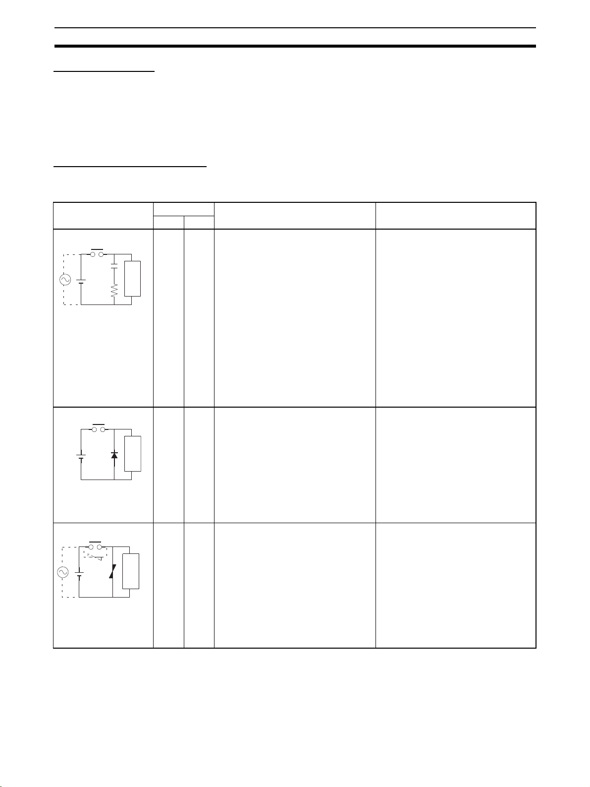
Countermeasure Examples
When switching an inductive load, connect an surge protector, diodes, etc., in
parallel with the load or contact as shown below.
Circuit Current Characteristic Required element
AC DC
CR method
C
R
Powe r
supply
Diode method
Powe r
supply
Varistor method
Powe r
supply
Yes Yes If the load is a relay or solenoid, there is
a time lag between the moment the circuit is opened and the moment the load
is reset.
If the supply voltage is 24 or 48 V, insert
Inductive
load
the surge protector in parallel with the
load. If the supply voltage is 100 to
200 V, insert the surge protector
between the contacts.
No Yes The diode connected in parallel with
the load changes energy accumulated
by the coil into a current, which then
flows into the coil so that the current will
be converted into Joule heat by the
Inductive
load
resistance of the inductive load.
This time lag, between the moment the
circuit is opened and the moment the
load is reset, caused by this method is
longer than that caused by the CR
method.
Yes Yes The varistor method prevents the impo-
sition of high voltage between the contacts by using the constant voltage
characteristic of the varistor. There is
time lag between the moment the cir-
Inductive
load
cuit is opened and the moment the load
is reset.
If the supply voltage is 24 or 48 V, insert
the varistor in parallel with the load. If
the supply voltage is 100 to 200 V,
insert the varistor between the contacts.
The capacitance of the capacitor must
be 1 to 0.5
µF per contact current of
1 A and resistance of the resistor must
be 0.5 to 1 Ω per contact voltage of 1 V.
These values, however, vary with the
load and the characteristics of the
relay. Decide these values from experiments, and take into consideration that
the capacitance suppresses spark discharge when the contacts are separated and the resistance limits the
current that flows into the load when
the circuit is closed again.
The dielectric strength of the capacitor
must be 200 to 300 V. If the circuit is an
AC circuit, use a capacitor with no
polarity.
The reversed dielectric strength value
of the diode must be at least 10 times
as large as the circuit voltage value.
The forward current of the diode must
be the same as or larger than the load
current.
The reversed dielectric strength value
of the diode may be two to three times
larger than the supply voltage if the
surge protector is applied to electronic
circuits with low circuit voltages.
---
xxxi
Page 31

Conformance to EC Directives 6
r
When switching a load with a high inrush current such as an incandescent
lamp, suppress the inrush current as shown below.
Countermeasure 1
OUT
R
COM
Providing a dark current of
approx. one-third of the rated
value through an incandescent
lamp
Countermeasure 2
R
OUT
COM
Providing a limiting resisto
6-5 Conditions for Meeting EMC Directives when Using CPM1A Relay
Expansion I/O Units
EN61131-2 immunity testing conditions when using the CP1W-40EDR,
CPM1A-40EDR, CP1W-16ER, or CPM1A-16ER with a CP1W-CN811 I/O
Connecting Cable are given below.
Recommended Ferrite Core
Ferrite Core (Data Line Filter): 0443-164151 manufactured by Nisshin Electric
Minimum impedance: 90 Ω at 25 MHz, 160 Ω at 100 MHz
30
32 33
Recommended Connection Method
1,2,3... 1. Cable Connection Method
xxxii
Page 32

Conformance to EC Directives 6
2. Connection Method
As shown below, connect a ferrite core to each end of the CP1W-CN811
I/O Connecting Cable.
SYSMAC
IN
CP1L
L1 L2/N
COM 01 03 05 07 09 11 01 03 05 07 09 11
00 02 04 06 08 10 00 02 04 06 08
10
00 01 02 03 04 06 00 01 03 04 06
COM COM COM COM 05 07 COM 02 COM 05
OUT
07
COM
NCNCNC
01 03 05 07 09 11 01 03 05 07 09 11
NC
00 02 04 06 08 10
00 02 04 06 08 10
CH CH
CH
IN
CH
CH
OUT
CH
111009080706050403020100
111009080706050403020100
0706050403020100
0706050403020100
CH CH
NC
00 01 02 04 05 07 00 02 04 05 07
NC
COM COM COM COM COM COM03 06 01 03 06
40EDR
EXP
xxxiii
Page 33

Conformance to EC Directives 6
xxxiv
Page 34

SECTION 1
Features and System Configuration
This section introduces the features of the CP1L and describes its configuration. It also describes the Units that are available
and connection methods for the CX-Programmer and other peripheral devices.
1-1 Features and Main Functions . . . . . . . . . . . . . . . . . . . . . . . . . . . . . . . . . . . . . 2
1-1-1 CP1L Overview . . . . . . . . . . . . . . . . . . . . . . . . . . . . . . . . . . . . . . . . 2
1-1-2 Features. . . . . . . . . . . . . . . . . . . . . . . . . . . . . . . . . . . . . . . . . . . . . . . 5
1-2 System Configuration . . . . . . . . . . . . . . . . . . . . . . . . . . . . . . . . . . . . . . . . . . . 12
1-2-1 Basic System. . . . . . . . . . . . . . . . . . . . . . . . . . . . . . . . . . . . . . . . . . . 12
1-2-2 System Expansion. . . . . . . . . . . . . . . . . . . . . . . . . . . . . . . . . . . . . . . 14
1-2-3 Restrictions on System Configuration . . . . . . . . . . . . . . . . . . . . . . . 17
1-3 Connecting the CX-Programmer . . . . . . . . . . . . . . . . . . . . . . . . . . . . . . . . . . 20
1-3-1 Connecting with a Commercially Available USB Cable . . . . . . . . . 20
1-3-2 Connecting to a Serial Port. . . . . . . . . . . . . . . . . . . . . . . . . . . . . . . . 27
1-4 Function Charts. . . . . . . . . . . . . . . . . . . . . . . . . . . . . . . . . . . . . . . . . . . . . . . . 29
1-5 Function Blocks . . . . . . . . . . . . . . . . . . . . . . . . . . . . . . . . . . . . . . . . . . . . . . . 30
1-5-1 Overview of Function Blocks . . . . . . . . . . . . . . . . . . . . . . . . . . . . . . 30
1-5-2 Advantages of Function Blocks . . . . . . . . . . . . . . . . . . . . . . . . . . . . 30
1
Page 35

Features and Main Functions Section 1-1
1-1 Features and Main Functions
1-1-1 CP1L Overview
The SYSMAC CP1L PLCs are the low end PLCs in the SYSMAC CP Series
of package-type Programmable Controllers. They have the smallest program
and I/O capacity. The CP1L PLCs are the same size as the CPM1A and
CPM2A PLCs, but offer many more features and high performance.
CPU Units with 40 I/O Points: CP1L-M40D@-@ CPU Units with 30 I/O Points: CP1L-M30D@-@
• The CPU Unit has 24 inputs and 16 outputs built
in.
• The PLC can be expanded to a maximum total of
160 I/O points by using CP-series Expansion I/O
Units.
• The CPU Unit has 18 inputs and 12 outputs built
in.
• The PLC can be expanded to a maximum total of
150 I/O points by using CP-series Expansion I/O
Units.
24 built-in inputs (Functions
can be assigned.) (See note.)
Normal inputs (24)
Interrupt inputs (6)
Quick-response inputs (6)
16 built-in outputs (Functions
can be assigned.) (See note.)
Normal outputs (16)
High-speed counter
(4 counters/2 axes)
100 kHz (single phase)
2 pulse outputs
100 kHz
18 built-in inputs (Functions
can be assigned.) (See note.)
Normal inputs (18)
Interrupt inputs (6)
Quick-response inputs (6)
12 built-in outputs (Functions
can be assigned.) (See note.)
Normal outputs (12)
High-speed counter
(4 counters/2 axes)
100 kHz (single phase)
2 pulse outputs
100 kHz
2 PWM outputs
CPU Units with transistor outputs only. CPU Units with transistor outputs only.
2 PWM outputs
• Four high-speed counters for two axes and two pulse outputs for two axes
can be used with the CPU Unit alone.
• Using CP-series Expansion Units also allows extra functions (such as
temperature sensor inputs) to be added.
• Installing an Option Board enables RS-232C and RS-422A/485 communications for Programmable Terminals, Bar Code Readers, Inverters, etc.
2
Page 36

Features and Main Functions Section 1-1
Note Settings in the PLC Setup determine whether each input point is to be used
as a normal input, interrupt input, quick-response input, or high-speed
counter. The instruction used to control each output point determines whether
it is used as a normal output, pulse output, or PWM output.
CPU Units with 20 I/O Points: CP1L-L20D@-@ CPU Units with 14 I/O Points: CP1L-L14D@-@
• The CPU Unit has 12 inputs and 8 outputs built in. • The CPU Unit has 8 inputs and 6 outputs built in.
• The PLC can be expanded to a maximum total of
60 I/O points by using CP-series Expansion I/O
Units.
• The PLC can be expanded to a maximum total of
54 I/O points by using CP-series Expansion I/O
Units.
12 built-in inputs (Functions
can be assigned.) (See note.)
Normal inputs (12)
Interrupt inputs (6)
Quick-response inputs (6)
8 built-in outputs (Functions
can be assigned.) (See note.)
Normal outputs (8)
High-speed counter
(4 counters/2 axes)
100 kHz (single phase)
2 pulse outputs
100 kHz
8 built-in inputs (Functions can
be assigned.) (See note.)
Normal inputs (8)
Interrupt inputs (4)
Quick-response inputs (4)
12 built-in outputs (Functions
can be assigned.) (See note.)
Normal outputs (6)
High-speed counter
(4 counters/2 axes)
100 kHz (single phase)
2 pulse outputs
100 kHz
2 PWM outputs
CPU Units with transistor outputs only. CPU Units with transistor outputs only.
2 PWM outputs
• Four high-speed counters for two axes and two pulse outputs for two axes
can be used with the CPU Unit alone.
• Using CP-series Expansion Units also allows extra functions (such as
temperature sensor inputs) to be added.
• Installing an Option Board enables RS-232C and RS-422A/485 communications for Programmable Terminals, Bar Code Readers, Inverters, etc.
Note Settings in the PLC Setup determine whether each input point is to be used
as a normal input, interrupt input, quick-response input, or high-speed
counter. The instruction used to control each output point determines whether
it is used as a normal output, pulse output, or PWM output.
3
Page 37

Features and Main Functions Section 1-1
CP1L CPU Units
I/O capacity 40 points 30 points 20 points 14 points
Model CP1L-M40DR-A
CP1L-M40DR-D
CP1L-M40DT-D
CP1L-M40DT1-D
Power supply Models with AC power (model numbers ending in “-A”):
100 to 240 V AC, 50/60 Hz
Models with DC power (model numbers ending in “-D”):
24 V DC
Program capacity 10K steps 5K steps
Maximum number of I/O points 160 (See note 1.) 150 (See note 1.) 60 (See note 2.) 54 (See note 2.)
Normal I/O I/O points 40 30 20 14
Input points 24 18 12 8
Input specifications 24 VDC
Interrupt or quick-
6 max. 4 max.
response inputs
Output points 16 12 8 6
Output specifications Relay outputs: Model numbers with “R” before the final suffix
Transistor outputs, sinking: Model numbers with “T” before the final suffix
Transistor outputs, sourcing:Model numbers with “T1” before the final suffix
High-speed counter inputs 4 counters/2 axes, 100 kHz (single-phase),
100 kHz for up/down pulses or pulse plus direction, 50 kHz for differential phases
Pulse outputs 2 axes, 100 kHz (transistor outputs)
CP1L-M30DR-A
CP1L-M30DR-D
CP1L-M30DT-D
CP1L-M30DT1-D
CP1L-L20DR-A
CP1L-L20DR-D
CP1L-L20DT-D
CP1L-L20DT1-D
CP1L-L14DR-A
CP1L-L14DR-D
CP1L-L14DT-D
CP1L-L14DT1-D
Note (1) Three Expansion I/O Units connected to a CP-series CPU Unit with 40
I/O Points.
(2) One Expansion I/O Unit connected to a CP-series CPU Unit with 40 I/O
Points.
Interpreting CP1L CPU Unit Model Numbers
Program capacity
M: 10K steps
L: 5K steps
Number of built-in
normal I/O points
40: 40
30: 30
20: 20
14: 14
Input classification
D: DC inputs
CP1L-@@@D@-@
Power supply
A: AC
D: DC
Output classification
R: Relay outputs
T: Transistor outputs (sinking)
T1: Transistor outputs (sourcing)
4
Page 38

Features and Main Functions Section 1-1
k
1-1-2 Features
This section describes the main features of the CP1L.
Basic CP1L Configuration
CX-One
CP1L CPU Unit (Example for model with 40 I/O points)
USB cable
Analog adjuster
External analog
settings input
USB port
Peripheral
USB port
Memory Cassette
CP1W-ME05M
Memory Cassette
Battery (CJ1W-BAT01)
Two Option Board slots
Option Board
Power supply/input terminal bloc
Output terminal block
Positioning with an
Inverter
One RS-232C port
CP1W-CIF01 RS-232C
Option Board
One RS-422A/485 port
CP1W-CIF11 RS-422A/485
Option Board
Positioning can be controlled using an inverter. Previous a internal pulse output with trapezoidal acceleration/deceleration is created using the PULSE
OUTPUT instruction. The position offset is calculated using an error counter
for the feedback pulse input from a rotary encoder connected to an inductive
motor and the internal pulse output. The error counter is then used to output a
speed command to the inverter to control positioning. This enables positioning
with high-capacity motors, as well as low-cost positioning with small-capacity
motors (in comparison to using a servo).
5
Page 39

Features and Main Functions Section 1-1
A virtual pulse output is created using a pulse output instruction, the position
offset is calculated using an error counter, and a frequency (i.e., speed)
command is output according to the position offset to control positioning.
Analog output or RS-422A (Modbus-RTU)
Pulse Output
Instruction
Pulse input
Frequency
command
Inverter
Note If high-precision positioning is required, we recommend using an inverter with
Full Complement of
High-speed Counter
Functions
Encoder
Motor
vector control.
High-speed counter inputs can be enabled by connecting rotary encoders to
the built-in inputs. The ample number of high-speed counter inputs makes it
possible to control a multi-axis device with a single PLC.
• Four 100-kHz (single phase)/50-kHz (differential phases) high-speed
counter inputs (4 counters/2 axes) are provided as a standard feature.
(See note.)
24 built-in inputs
(Functions can be assigned.)
High-speed counters
(4 counters/2 axes)
100 kHz (single phase)
Note Settings in the PLC Setup determine whether each input point is to
be used as a normal input, interrupt input, quick-response input, or
high-speed counter.
6
Page 40

Features and Main Functions Section 1-1
Full Complement of Highspeed Counter Functions
Versatile Pulse
Control (CPU Units
with Transistor
Outputs Only)
High-speed Processing for High-speed Counter Present Value (PV)
Target Values or Range Comparison Interrupts
An interrupt task can be started when the count reaches a specified value or
falls within a specified range.
High-speed Counter Input Frequency (Speed) Monitoring
The input pulse frequency can be monitored using the PRV instruction (one
point (counter 0) only, and you must select whether to use input frequency
monitoring or counter 3; you cannot use both).
High-speed Counter PV Holding/Refreshing
It is possible to toggle between holding and refreshing the high-speed counter
PV by turning ON and OFF the High-speed Counter Gate Flag from the ladder
program.
Positioning and speed control by a pulse-input servo driver is enabled by outputting fixed duty ratio pulse output signals from the CPU Unit's built-in outputs.
• Pulse outputs for 2 axes at 100 kHz maximum are provided as standard
features. (See note.)
Full Complement of Pulse
Output Functions
16 built-in outputs
(Functions assigned.)
2 pulse outputs
100 kHz
Note The instruction used to control each output point determines
whether it is used as a normal output, pulse output, or PWM output.
Select CW/CCW Pulse Outputs or Pulse Plus Direction Outputs for the
Pulse Outputs
The pulse outputs can be selected to match the pulse input specifications of
the motor driver.
Easy Positioning with Absolute Coordinate System Using Automatic
Direction Setting
For operations in an absolute coordinate system (i.e., when the origin is
established or when the PV is changed by the INI instruction), the CW/CCW
direction can be automatically set when PULSE OUTPUT instructions are
executed according to whether the specified number of output pulses is more
or less than the pulse output PV.
7
Page 41

Features and Main Functions Section 1-1
Triangular Control
If the amount of output pulses required for acceleration and deceleration (the
target frequency times the time to reach the target frequency) exceeds the
preset target number of output pulses during positioning (when the ACC
instruction in independent mode or the PLS2 instruction is executed), the
acceleration and deceleration will be shortened and triangular control will be
executed instead of trapezoidal control. In other words, the trapezoidal pulse
output will be eliminated, with no period of constant speed.
Target Position Changes during Positioning (Multiple Start)
While positioning using a PULSE OUTPUT (PLS2) instruction is in progress,
the target position, target speed, acceleration rate, and deceleration rate can
be changed by executing another PLS2 instruction.
Positioning Changes during Speed Control (Interrupt Feeding)
While speed control in continuous mode is in effect, it is possible to change to
positioning in independent mode by executing a PULSE OUTPUT (PLS2)
instruction. By this means, interrupt feeding (moving a specified amount) can
be executed under specified conditions.
Target Speed, Acceleration Rate, and Deceleration Rate Changes during
Acceleration or Deceleration
When a PULSE OUTPUT instruction with trapezoidal acceleration and deceleration is executed (for speed control or positioning), the target speed and
acceleration and deceleration rates can be changed during acceleration or
deceleration.
Lighting and Power Control by Outputting Variable Duty Ratio Pulses
Operations, such as lighting and power control, can be handled by outputting
variable duty ratio pulse (PWM) output signals from the CPU Unit's built-in
outputs.
Origin Searches Origin Search and Origin Return Operations Using a Single Instruction
An accurate origin search combining all I/O signals (origin proximity input signal, origin input signal, positioning completed signal, error counter reset output, etc.) can be executed with a single instruction. It is also possible to move
directly to an established origin using an origin return operation.
Input Interrupts In direct mode, an interrupt task can be started when a built-in input turns ON
or OFF. In counter mode, the rising or falling edges of built-in inputs can be
counted, and an interrupt task started when the count reaches a specified
value. The maximum number of interrupt input points is 6 for CPU Units with
20, 30, or 40 I/O points and 4 for CPU Units with 14 I/O points.
Note For each input point, a selection in the PLC Setup determines whether it is to
be used as a normal input, interrupt input, quick-response input, or highspeed counter. The interrupt input response frequency in counter mode must
be 5 kHz or less total for all interrupts.
Quick-response
Inputs
By using quick-response inputs, built-in inputs up to a minimum input signal
width of 50
ber of quick-response input points is 6 for CPU Units with 20, 30, or 40 I/O
points and 4 for CPU Units with 14 I/O points.
µs can be read regardless of the cycle time. The maximum num-
Note For each input, a PLC Setup parameter determines whether it is to be used as
a normal input, interrupt input, quick-response input, or high-speed counter.
8
Page 42

Features and Main Functions Section 1-1
Analog Settings
Changing Settings Using
Analog Adjustment
Changing Settings Using
External Analog Setting
Inputs
By adjusting the analog adjuster with a Phillips screwdriver, the value in the
Auxiliary Area can be changed to any value between 0 and 255. This makes it
easy to change set values such as timers and counters without Programming
Devices.
Phillips screwdriver
Analog adjuster
Ladder program
CNTX
A642
Example: The production quantity could be changed by
changing the counter set value from 100 to 150.
Turning the control on the CP1H changes the
PV in A642 between 0000 and 0255 (00 and
FF hex).
External analog values of 0 to 10 V (resolution: 256) are converted to digital
values and stored in a word in the AR Area. This enables applications that
require on-site adjustment of settings that do not demand a particularly high
degree of accuracy, such as for example, a setting based on changes in outdoor temperatures or potentiometer inputs.
External analog setting
input connector
Potentiometer, temperature
sensor, etc.
0 to 10 V
Ladder program
TIMX
A643
Example: The production quantity could be changed by changing
the timer set value from 100 to 150.
When a voltage (0 to 10 V) is input from a
device such as a potentiometer to the
external analog setting input, the PV in A643
is refreshed between 0000 and 0100 hex (0
to 256).
9
Page 43

Features and Main Functions Section 1-1
Connectability with Various Components
USB Port for
Programming Devices
Expansion Capability for
Serial Ports
CX-One Support Software, such as the CX-Programmer, connects from the
USB port on a computer to the CP1L built-in peripheral USB port via commercially available USB cable.
Personal computer
CX-One (ver. 2.0 or higher)
(e.g., CX-Programmer ver. 7.1 or higher)
USB port
USB cable
Peripheral
USB port
Up to two Serial Communications Boards each with one RS-232C port or one
RS-422A/485 port can be added to a CPU Unit with 30 or 40 I/O points. One
Serial Communications Boards can be added to a CPU Unit with 20 or 14 I/O
points. With a total of up to three ports, including the USB port, this makes it
possible to simultaneously connect a computer, PT, CP1L, and/or various
components, such as an Inverter, Temperature Controller, or Smart Sensor.
NS-series PT, personal computer, bar code reader, etc.
RS-232C
CP1L
RS-422A
CP1W-CIF01 RS-232C
Option Board
CP1W-CIF11 RS-422A/485
Option Board
Inverter, etc. (See note 1.)
CP1L
10
Note (1) The Modbus-RTU easy master (available for all models) makes it easy to
control Modbus Slaves (such as Inverters) with serial communications.
After the Modbus Slave address, function, and data have been preset in
Page 44

Features and Main Functions Section 1-1
r
a fixed memory area (DM), messages can be sent or received independently of the program by turning software switches.
Communications can be executed
independently of the program by setting
a Modbus-RTU command in the DM and
turning ON a software switch.
(2) By using the serial PLC Links, a maximum of 10 words of data per CPU
Unit can be shared independently of the program among a maximum of
nine CPU Units (CP1L-CP1L-CP1H/CJ1M) using RS-422A/485 Option
Boards.
Modbus-RTU
Inverte
CP1L CPU Unit
(Master)
RS-422A/485
Data sharing
CP1L CPU Unit
(Slave)
CP1L CPU Unit
(Slave)
8 CPU Units max.
CJ1M CPU Unit
(Slave)
No-battery Operation Programs, the PLC Setup, and other data can be automatically saved to the
CPU Unit's built-in flash memory. Moreover, DM Area data can be saved to
the flash memory and then used as initial data when the power is turned ON.
This allows programs and initial values (such as recipe setup data) in the DM
Area to be saved in the CPU Unit without the need to maintain a backup battery.
11
Page 45

System Configuration Section 1-2
CP1L CPU Unit
Built-in flash
memory
Programs, DM initial values, etc.
Data saving capability
without a battery
Memory Cassettes Built-in flash memory data, such as programs and DM initial-value data, can
be stored on a Memory Cassette (optional) as backup data. In addition, programs and initial-value data can be easily copied to another CPU Unit using
the Memory Cassette to recreate the same system.
CP1L CPU Unit Another CP1L CPU Unit
Built-in flash
memory
Memory
Cassette
Can be automatically
transferred at startup.
Programs, DM initial values, etc.
Security A password registration function is provided for the CPU Unit to prevent unau-
thorized copy of ladder programs. If an attempt is made to read a ladder program from a CX-Programmer, access to the program is denied if the password
that is entered does not match the registered password. If incorrect passwords are entered for five consecutive attempts, the CPU Unit does not
accept any more passwords for two hours.
1-2 System Configuration
1-2-1 Basic System
CPU Unit with 40 I/O Points CPU Unit with 30 I/O Points CPU Unit with 20 I/O Points CPU Unit with 14 I/O Points
12
Page 46

System Configuration Section 1-2
Maximum Number of Normal I/O Points
Type I/O
capacity
M 40 points 100 to 240 VAC CP1L-M40DR-A 24 DC inputs 16 relay outputs 675 g max.
30 points 100 to 240 VAC CP1L-M30DR-A 18 DC inputs 12 relay outputs 610 g max.
L 20 points 100 to 240 VAC CP1L-L20DR-A 12 DC inputs 8 relay outputs 380 g max.
14 points 100 to 240 VAC CP1L-L14DR-A 8 DC inputs 6 relay outputs 380 g max.
Power supply
voltage
24 VDC CP1L-M40DR-D 590 g max.
24 VDC CP1L-M30DR-D 525 g max.
24 VDC CP1L-L20DR-D 350 g max.
24 VDC CP1L-L14DR-D 350 g max.
Model Normal built-in
inputs
CP1L-M40DT-D 16 transistor (sinking)
CP1L-M40DT1-D 16 transistor (sourcing)
CP1L-M30DT-D 12 transistor (sinking)
CP1L-M30DT1-D 12 transistor (sourcing)
CP1L-L20DT-D 8 transistor (sinking)
CP1L-L20DT1-D 8 transistor (sourcing)
CP1L-L14DT-D 6 transistor (sinking)
CP1L-L14DT1-D 6 transistor (sourcing)
Normal built-in
outputs
outputs
outputs
outputs
outputs
outputs
outputs
outputs
outputs
Weight
550 g max.
550 g max.
495 g max.
495 g max.
335 g max.
335 g max.
335 g max.
335 g max.
Optional Products
Serial
Communications
Expansion
Item Model Specifications Weight
Memory
Cassette
CP1W-ME05M Can be used to store user programs in
flash memory, parameters, DM initial
values, comment memory, FB programs, and data in RAM.
10 g max.
When serial communications are required for a CP1L CPU Unit, an RS-232C
or RS-422A/485 Option Board can be added.
Two Option Boards can be mounted with a CPU Units with 30 or 40 I/O points
and one Option Board can be mounted with a CPU Units with 20 or 14 I/O
points.
This enables connection by serial communications to NS-series PTs, Bar
Code Readers, components such as Inverters, and computers without USB
ports (such as when using the CX-Programmer).
13
Page 47

System Configuration Section 1-2
NS-series PT, personal computer, bar code reader, etc.
CP1W-CIF01 RS-232C
Option Board
RS-232C
(Expansion)
CP1W-CIF11 RS-422A/485C
Option Board
RS-422A (Expansion)
Inverter, etc.
Option Boards for Serial Communications
Appearance Name Model Port Serial communications modes
COMM
COMM
RS-232C
Option Board
RS-422A/485
Option Board
CP1W-CIF01 One RS-232C port
(D-Sub, 9 pins,
female)
CP1W-CIF11 One RS-422A/485
port (terminal block
for ferrules)
Host Link, NT Link (1: N or
Link Master, 1:1 Link Slave
No-protocol, Serial PLC Link
Slave, Serial PLC Link Master,
Serial Gateway (conversion to
CompoWay/F, conversion to Modbus-RTU), peripheral bus
1:1
),
1-2-2 System Expansion
CP-series Expansion Units or Expansion I/O Units can be connected to a
CP1L CPU Unit. Up to three Expansion Units or Expansion I/O Units can be
connected to a CPU Unit with 30 or 40 I/O points and one Expansion Unit or
Expansion I/O Unit can be connected to a CPU Unit with 20 or 14 I/O points.
This allows for the expansion of various functions such as I/O points or temperature sensor inputs.
14
Page 48

System Configuration Section 1-2
CP1L CPU Unit with 30 or 40 I/O Points
CP1L CPU Unit with 20 or 14 I/O Points
Maximum I/O Points
Up to three Expansion Units or Expansion I/O Units can be connected to a
CPU Unit with 30 or 40 I/O points and one Expansion Unit or Expansion I/O
Unit can be connected to a CPU Unit with 20 or 14 I/O points. The maximum
I/O capacity is thus achieved by connecting either one or three Expansion
Units or Expansion I/O Units.
Type I/O capacity Model Built-in
inputs
M 40 points CP1L-M40DR-A
CP1L-M40DR-D
CP1L-M40DT-D
CP1L-M40DT1-D
30 points CP1L-M30DR-A
CP1L-M30DR-D
CP1L-M30DT-D
CP1L-M30DT1-D
L 20 points CP1L-L20DR-A
CP1L-L20DR-D
CP1L-L20DT-D
CP1L-L20DT1-D
14 points CP1L-L14DR-A
CP1L-L14DR-D
CP1L-L14DT-D
CP1L-L14DT1-D
24 16 3 Units max.
18 12 3 Units max.
12 8 1 Unit max.
861 Unit max.
A maximum of three CP-series Expansion
I/O Units or Expansion Units can be added.
One CP-series Expansion I/O Unit or
Expansion Unit can be added.
Built-in
outputs
Maximum number of
Expansion I/O Units or
Expansion Units
Inputs: 24 × 3
Outputs: 16 × 3
Inputs: 24 × 3
Outputs: 16 × 3
Inputs: 24
Outputs: 16
Inputs: 24
Outputs: 16
Maximum total I/O
points
Max.: 160 points
Inputs: 96 points
Outputs: 64 points
Max.: 150 points
Inputs: 90 points
Outputs: 60 points
Max.: 60 points
Inputs: 36 points
Outputs: 24 points
Max.: 54 points
Inputs: 32 points
Outputs: 22 points
CP-series Expansion I/O Units
Appearance Model Normal
NCNCNC
COM
01 03 05 07 09 11 01 03 05 07 09 11
NC
00 02 04 06 08 10
00 02 04 06 08 10
CH CH
CH
111009080706050403020100
IN
CH
111009080706050403020100
CH
0706050403020100
OUT
CH
0706050403020100
CH CH
NC
00 01 02 04 05 07 00 02 04 05 07
NC
COM COM COM COM COM COM03 06 01 03 06
EXP
CP1W-40EDR
CPM1A-40EDR
CP1W-40EDT
CPM1A-40EDT
CP1W-40EDT1
CPM1A-40EDT1
inputs
24 VDC:
24 inputs
Normal outputs Weight
16 relay outputs 380 g max.
16 transistor outputs (sink-
320 g max.
ing)
16 transistor outputs (sourc-
ing)
15
Page 49

System Configuration Section 1-2
Appearance Model Normal
COM 01 03 0 5 0 7 0 9 11
NC 00 02 04 06 08 10
CH
IN
CH
00 01 02 03
04 05 06 07
08 09 10 11
OUT
CH
00 01 02 03 04 05 06 07
CH
EXP
NC 00 01 02 04 05 07
NC COM COM COM 03 COM
06
01COM
03
00 02
IN
CH
00 01 02 03
08 09 10
11
EXP
06
04
COM 05 07
CP-series Expansion Units
Name and
appearance
Analog I/O Units CPM1A-MAD01 2 analog
MAD01
IN
OUT
CH
EXP
CH
I OUT V IN1 COM1 I IN2
V OUT COM I IN1 V IN2 COM2
NC
NC
inputs
Normal outputs Weight
CP1W-20EDR1
CPM1A-20EDR1
CP1W-20EDT
24 VDC:
12 inputs
8 relay outputs 300 g max.
8 transistor outputs (sinking)
CPM1A-20EDT
CP1W-20EDT1
CPM1A-20EDT1
CP1W-16ER
None 16 relay outputs 280 g max.
8 transistor outputs (sourcing)
CPM1A-16ER
CP1W-8ED
CPM1A-8ED
CP1W-8ER
24 VDC:
None 200 g max.
8 inputs
None 8 relay outputs 250 g max.
CPM1A-8ER
CP1W-8ET
8 transistor outputs (sinking)
CPM1A-8ET
CP1W-8ET1
CPM1A-8ET1
8 transistor outputs (sourcing)
Model Specifications Weight
CP1W-MAD11
CPM1A-MAD11
inputs
1 analog
output
2 analog
inputs
0 to 10 V/1 to 5 V/4
to 20 mA
0 to 10 V/−10 to
+10 V/4 to 20 mA
0 to 5 V/1 to 5 V/0 to
10 V/−10 to +10 V/0
Resolution: 256
Resolution: 6,000
to 20 mA/4 to 20 mA
1 analog
output
1 to 5/0 to 10 V/−10
to +10 V/0 to 20
mA/4 to 20 mA
150 g max.
Analog Input
Units
IN
CH
VIN2
VIN4
I IN1 I IN3
COM2
COM4NCAG
COM3
VIN1
VIN3COM1
I IN2
I IN4
Analog Output
Units
OUT
CH
VOUT4
VOUT2
I OUT1 I OUT3
COM4NCAG
COM2
COM3
VOUT1
VOUT3
COM1
I OUT2
I OUT4
Temperature
Sensor Units
CP1W-AD041
CPM1A-AD041
CP1W-DA041
CPM1A-DA041
CP1W-TS001
CPM1A-TS001
CP1W-TS002
CPM1A-TS002
CP1W-TS101
CPM1A-TS101
CP1W-TS102
CPM1A-TS102
4 analog
inputs
0 to 5 V/1 to 5 V/0 to
10 V/−10 to +10 V/
Resolu-
tion: 6,000
0 to 20 mA/
4 to 20 mA
4 analog
outputs
1 to 5 V/0 to 10 V/
−10 to +10 V/
0 to 20 mA/
4 to 20 mA
2 inputs Thermocouple input
K, J
4 inputs
2 inputs Platinum resistance thermometer
input
4 inputs
Pt100, JPt100
200 g max.
250 g max.
16
Page 50

System Configuration Section 1-2
Name and
Model Specifications Weight
appearance
DeviceNet I/O
Link Unit
CompoBus/S
I/O Link Unit
No.
S
COMM
ERR
SRT21
BD H NC(BS+)
BD L NC(BS-) NC
CPM1A-DRT21 As a DeviceNet Slave, 32 inputs and 32 out-
puts are allocated.
CP1W-SRT21
CPM1A-SRT21
EXP
As a CompoBus/S slave, 8 inputs and 8 outputs are allocated.
1-2-3 Restrictions on System Configuration
The following restrictions apply to the CP-series Expansion Units and CPseries Expansion I/O Units that can be connected to CP1L CPU Units.
■ Number of Expansion Units and Expansion I/O Units Connected
A maximum of three Units can be connected to a CPU Unit with 30 or 40 I/O
points and one Unit can be connected to a CPU Unit with 20 or 14 I/O points.
200 g max.
200 g max.
■ Mounting Restriction
When connecting CP-series or CPM1A-series Expansion Units or Expansion
I/O Units to a CPU Unit with AC power, provide a space of approximately 10
mm between the CPU Unit and the first Expansion Unit or Expansion I/O Unit.
CP1L CPU Unit
10 mm
Expansion I/O Units or Expansion Units
If sufficient space cannot be provided between the CPU Unit and the first
Expansion Unit or Expansion I/O Unit, use the PLC in an ambient temperature
of 0 to 50
■ Restrictions in the External Power Supply Capacity
°C.
The following restrictions apply when using the external power supply from a
CPU Unit with AC power.
CPU Units with 30 or 40 I/O Points and AC Power (CP1L-M
@@DR-A)
When CP1W or CPM1A Expansion Units or Expansion I/O Units are connected to a CPU Unit with 30 or 40 I/O Points and AC Power (CP1L-M@@DR-
A), it may not be possible to use the entire 300 mA from the external power
supply due to restrictions in the power supply capacity. The entire 300 mA
from the external power supply can be used if Expansion Units and Expansion
I/O Units are not connected.
17
Page 51

System Configuration Section 1-2
C
C
C
Calculation Examples of Restrictions in External Power Supply Capacity
Calculate the external power supply capacity using the following calculation
example.
Item CPU Unit Expansion Unit Total Restriction
1st Unit 2nd Unit 3rd Unit
CP1L-M40DR-A CP1W-DA041 CP1W-DA041 CP1W-DA041
5 V 0.22 A 0.08 A 0.08 A 0.08 A 0.46 A
24 V 0.08 A 0.124 A 0.124 A 0.124 A 0.452 A
Power con-
sumption
Applicable
external power
supply capacity
5 V × 0.46 A = 2.3 W
13.148 W ≤ 18.5 W
24 V × 0.452 A = 10.848 W
18.5 W (total external power supply capacity)
− 13.148 W = 5.352 W
0.223 A ≤ 0.3 A
5.352 W/24V = 0.223 A
Note If the results exceeds 0.3 A, reduce the current consumption to 0.3 A or less.
CPU Units with 14 or 20 I/O Points and AC Power (CP1L-L
@@DR-A)
When CP1W or CPM1A Expansion Units or Expansion I/O Units are connected to a CPU Unit with 14 or 20 I/O Points and AC Power (CP1L-L@@DR-
A), the external power supply cannot be used. If no Expansion Units or
Expansion I/O Units are connected, up to 200 mA can be used.
CPU Units with DC Power
CPU Units with DC power do not have an external power supply.
■ Restrictions Imposed by Ambient Temperature
There are restrictions in the power supply voltage and output load current
imposed by the ambient temperature for CPU Units with DC power. Use the
CPU Unit within the following ranges of power supply voltage and output load
current.
CPU Units with Relay Outputs (CP1L-
@@@DR-D)
Relay Output Load Current Derating Curves for CPU Units and Expansion I/O
Units
CP1L-L14DR-D
CP1L-L20DR-D
100%
Power voltage:
21.6 VDC
50%
Power voltage:
20.4 VDC
0%
Ambient temperature
45
40
CP1L-M30DR-D CP1L-M40DR-D
55°
100%
50%
0%
Power voltage:
21.6 VDC
Power voltage:
20.4 VDC
Ambient temperature
4535
100%
50%
0%
°
55
Power
voltage:
21.6 VDC
Power
voltage:
20.4 VDC
35
Ambient temperature
°
45
50
55
18
Note The above restrictions, apply to the relay output load current from the CPU
Unit even if Expansion I/O Units are not connected.
Page 52

System Configuration Section 1-2
C
C
e
Using CP1W-8ER/16ER/20EDR1/40EDR or
CPM1A-8ER/16ER/20EDR1/40EDR Expansion I/O Units with
CPU Units with Transistor Outputs (CP1L-@@@DT@-D)
Relay Output Load Current Derating Curves for Expansion I/O Units
Expansion I/O Units added
to the
CP1L-L14DT@-D or
CP1L-L20DT@-D
100%
Expansion I/O Units added
to the
CP1L-M30DT@-D
100%
Expansion I/O Units added
to the
CP1L-M40DT@-D
100%
50%
0%
Power voltage:
21.6 VDC
Power voltage:
20.4 VDC
Ambient temperature
40 45
Power voltage:
21.6 VDC
50%
Power voltage:
20.4 VDC
0%
55
°
Ambient temperature
55
°C
4535
Power voltage:
21.6 VDC
50%
Power voltage:
20.4 VDC
0%
55
4535
Ambient temperatur
°
Note There are no restrictions on the transistor output load current from the CPU
Unit.
CPU Units with AC Power
There are no restrictions on the output load current from CPU Units with AC
power.
19
Page 53

Connecting the CX-Programmer Section 1-3
1-3 Connecting the CX-Programmer
The CX-Programmer (version 7.1 or higher), which runs on Windows, can be
used with CP-series CP1L PLCs. Computers running Support Software (e.g.,
the CX-Programmer) can be connected to the USB port or to a serial port.
Note A Programming Console cannot be used with CP1L PLCs.
1-3-1 Connecting with a Commercially Available USB Cable
Connect the computer running the CX-One Support Software (e.g., the CXProgrammer) using a commercially available USB cable to the peripheral USB
port on the CPU Unit.
Personal computer
CX-One (CX-Programmer, etc.)
USB port
USB cable
Restrictions when
Connecting by USB
Peripheral
USB port
In conformity with USB specifications, the following restrictions apply when
connecting a computer running Support Software.
• A USB connection is possible for only one CP-series PLC from a single
computer. It is not possible to connect multiple PLCs simultaneously.
• Do not disconnect the USB cable while the Support Software is connected online. Before disconnecting the USB cable, be sure to place the
application in offline status. If the USB cable is disconnected while online,
the situations described below will occur as a result of OS error.
• Windows Me, 2000, or XP:
The Support Software cannot be returned to online status by simply reconnecting the USB cable. First return the Support Software to offline
status, and then reconnect the USB cable. Then perform the online
connection procedure for the Support Software.
• Windows 98:
If the USB cable is disconnected while online, an error message may
be displayed on a blue screen. If that occurs, it will be necessary to reboot the computer.
The peripheral USB port (conforming to USB 1.1, B connector) is a dedicated
port for connecting Support Software, such as the CX-Programmer.
Items Required for USB Connection
Operating system Windows 98, Me, 2000, or XP
Support Software CX-Programmer Ver. 6.1 (CX-One Ver. 1.1)
USB driver Included with above Support Software.
USB cable USB 1.1(or 2.0) cable (A connector-B connector), 5 m max.
20
Page 54

Connecting the CX-Programmer Section 1-3
Installing the USB Driver The procedure for first connecting a computer to the CP1L peripheral USB
port is described below.
It is assumed that the Support Software has already been installed in the
computer.
Windows XP
Turn ON the power supply to the CP1L, and connect USB cable between the
USB port of the computer and the peripheral USB port of the CP1L.
After the cable has been connected, the computer will automatically recognize
the device and the following message will be displayed.
1,2,3... 1. If the following window appears, select the No, not this time Option and
then click the Next Button. This window is not always displayed.
2. The following window will be displayed. Select the Install from a list of spe-
cific location Option and then click the Next Button.
21
Page 55

Connecting the CX-Programmer Section 1-3
3. The following window will be displayed. Click the Browse Button for the Include this location in the search Field, specify C:\Program Files\
OMRON\CX-Server\USB\win2000_XP\Inf, and then click the Next Button.
The driver will be installed. (“C:\” indicates the installation drive and may
be different on your computer.)
4. Ignore the following window if it is displayed and click the Continue Any-
way Button.
22
Page 56

Connecting the CX-Programmer Section 1-3
5. The following window will be displayed if the installation is completed normally. Click the Finish Button.
Windows 2000
Turn ON the power supply to the CP1L, and connect USB cable between the
USB port of the computer and the peripheral USB port of the CP1L.
After the cable has been connected, the computer will automatically recognize
the device and the following message will be displayed.
1,2,3... 1. The following message will be displayed. Click the Next Button.
23
Page 57

Connecting the CX-Programmer Section 1-3
2. The following window will be displayed.
3. Select the Search for a suitable driver for the device (recommended) Op-
tion and then click the Next Button. The following window will be displayed.
From the list in the window, select the Specify location Checkbox and then
click the Next Button.
24
4. Click the Browse Button, specify C:\Program Files\OMRON\CX-Server\USB\win2000_XP\Inf, and then click the Next Button. (“C:\” indicates
the installation drive and may be different on your computer.)
Page 58

Connecting the CX-Programmer Section 1-3
5. A search will be made for the driver and the following window will be displayed. Click the Next Button. The driver will be installed.
6. After the driver has been successfully installed, the following window will
be displayed. Click the Finish Button.
Connection Setup Using the CX-Programmer
1,2,3... 1. Select CP1L as the device type in the Change PLC Dialog Box and confirm
that USB is displayed in the Network Type Field.
25
Page 59

Connecting the CX-Programmer Section 1-3
2. Click the OK Button to finish setting the PLC model. Then connect to the
CP1L by executing the CX-Programmer's online connection command.
Checking after Installation
1,2,3... 1. Display the Device Manager at the computer.
2. Click USB (Universal Serial Bus) Controller, and confirm that OMRON
SYSMAC PLC Device is displayed.
Re-installing the USB
Driver
Checking USB Driver Status
1,2,3... 1. Display the Device Manager on the computer.
If the USB driver installation fails for some reason or is cancelled in progress,
the USB driver must be reinstalled.
2. If USB Device is displayed for Other devices, it means that the USB driver
installation has failed.
26
Page 60

Connecting the CX-Programmer Section 1-3
Reinstalling the USB Driver
1,2,3... 1. Right-click USB Device and select Delete from the pop-up menu to delete
the driver.
2. Reconnect the USB cable. The USB Driver Installation Window will be displayed.
3. Reinstall the USB driver.
1-3-2 Connecting to a Serial Port
Mounting a CP1W-CIF01 RS-232C Option Board in a CP1L Option Board slot
makes it possible to connect Support Software with serial communications,
just as with previous models.
Personal computer
CX-One (e.g., CX-Programmer)
D-Sub connector
Recommended cable
XW2Z-200S-CV (2 m) or
XW2Z-500S-CV (5 m)
(9-pin, female)
D-Sub connector
(9-pin, male)
CP1W-CIF01
RS-232C Option Board
Connect the CX-Programmer to the RS-232C port of the CP1W-CIF01 Option
Board by XW2Z-200S-CV/500S-CV RS-232C cable.
Connection Method Connect the Programming Device using the Connecting Cable that is appro-
priate for the serial communications mode of the computer and CPU Unit.
Computer Connecting Cable CP1L CPU Unit
Model Connector Model Length Connector Serial
IBM PC/AT or
compatible
D-Sub 9 pin,
male
XW2Z-200S-CV 2 m D-Sub 9 pin, female
XW2Z-500S-CV 5 m
(With a CP1W-CIF01 RS232C Option Board
mounted in Option Board
Slot 1 or 2.)
communications
mode
Peripheral bus or Host
Link (SYSWAY)
27
Page 61

Connecting the CX-Programmer Section 1-3
Serial Communications Mode
Serial
communications
mode
Peripheral bus
(toolbus)
Host Link
(SYSWAY)
This is the faster mode, so it is
generally used for CX-Programmer connections.
• Only 1: 1 connections are
possible.
• When a CP1L CPU Unit is
used, the baud rate is automatically detected by the Support Software.
A standard protocol for host
computers with either 1: 1 or 1:
N connections.
• Slower than the peripheral
bus mode.
• Allows modem or optical
adapter connections, or longdistance or 1: N connections
using RS-422A/485.
Features CPU Unit setting method
Turn ON pins SW4 (Serial Port
1) and SW5 (Serial Port 2) on
the DIP switch on the front
panel of the CPU Unit. These
settings enable connection by
peripheral bus regardless of the
serial port settings in the PLC
Setup.
Turn OFF pins SW4 (Serial Port
1) and SW5 (Serial Port 2) on
the DIP switch on the front
panel of the CPU Unit.
The mode will then be determined by the serial port settings in the PLC Setup. The
default settings are for Host
Link with a baud rate of 9,600
bits/s, 1 start bit, data length of
7 bits, even parity, and 2 stop
bits.
Note When a Serial Communications Option Board is mounted in Option Board
Slot 1, it is called “Serial Port 1.” When mounted in Option Board Slot 2, it is
called “Serial Port 2.”
28
Page 62

Function Charts Section 1-4
1-4 Function Charts
Built-in I/O functions
Built-in input functions Normal inputs
Selected in PLC Setup.
Interrupt inputs
High-speed counter inputs
Quick-response inputs
Built-in output functions
Selected by instructions.
Origin functions
Normal outputs
Pulse outputs
Variable duty ratio pulse outputs
(PWM outputs)
Origin search
Origin return
Execute the ORG instruction to move from any position to the origin.
Inverter positioning functions
Interrupt inputs (Direct mode)
Interrupt inputs (Counter mode)
No interrupts
High-speed counter interrupts
• Target value comparison interrupts
• Range comparison interrupts
Analog setting functions
No-battery operation
Memory Cassette
Data saved in the CPU Unit's built-in flash memory can be saved to a
Memory Cassette (purchased separately) and transferred automatically
from the Memory Cassette when the power supply is turned ON.
Clock
Functions using Option Boards
Functions using CPseries or CPM1A
Expansion Units
1 input
Analog adjustment
External analog setting
input
• Set value: 0 to 255
1 input, 0 to 10 V
• Resolution: 256
User memory, parameters (such as PLC Setup), DM initial
values, comment memory, etc., can be saved in the CPU
Unit's built-in flash memory.
Serial
communications
Analog I/O functions
Temperature sensor
input functions
CompoBus/S Slave
function
CompoBus/S I/O Link Unit
• Data exchanged with Master Unit: 8 inputs and 8 outputs
DeviceNet I/O Link Unit
DeviceNet Slave function
Data exchanged with DeviceNet Master: 32 inputs
and 32 outputs
29
Page 63

Function Blocks Section 1-5
1-5 Function Blocks
Function blocks can be used in programming SYSMAC CP-series PLCs.
1-5-1 Overview of Function Blocks
A function block is a basic program element containing a standard processing
function that has been defined in advance. Once the function block has been
defined, the user just has to insert the function block in the program and set
the I/O in order to use the function.
As a standard processing function, a function block is not created with actual
physical addresses, but local variables. The user sets parameters (addresses
or values) in those variables to use the function block. The addresses used for
the variables themselves are automatically assigned by the system (CX-Programmer) each time they are placed in the program.
In particular, each function block is saved by the CX-Programmer as an individual file that can be reused with programs for other PLCs. This makes it possible to create a library of standard processing functions.
Program 2
Standard program
section written
with variables
ccaa
bb
MOV
#0000
dd
Function block A
Define in advance.
Insert in program.
Program 1
Copy of function block A
Variable Variable Output
Input
Setting Setting
Copy of function block A
Variable Output
Save function
block as file.
Library
Function
block A
Reuse
To another PLC program
1-5-2 Advantages of Function Blocks
Function blocks allow complex programming units to be reused easily. Once
standard program sections have been created as function blocks and saved in
files, they can be reused just by placing a function block in a program and setting the parameters for the function block's I/O. Reusing standardized function
blocks reduces the time required for programming/debugging, reduces coding
errors, and makes programs easier to understand.
Structured
Programming
Easy-to-read “Block Box”
Design
Structured programs created with function blocks have better design quality
and required less development time.
The I/O operands are displayed as local variable names in the program, so
the program is like a “black box” when entering or reading the program and no
extra time is wasted trying to understand the internal algorithm.
Copy of function block A
Input
Variable Variable Output
30
Page 64

Function Blocks Section 1-5
Different Processes Easily
Created from a Single
Function Block
Reduced Coding Errors Coding mistakes can be reduced, because blocks that have already been
Data Protection The local variables in the function block cannot be accessed directly from the
Improved Reusability
through Programming
with Variables
Many different processes can be created easily from a single function block by
using input variables for the parameters (such as timer SVs, control constants, speed settings, and travel distances) in the standard process.
debugged can be reused.
outside, so the data can be protected. (Data cannot be changed unintentionally.)
The function block's I/O is entered as local variables, so the data addresses in
the function block do not have to be changed as they do when copying and
reusing a program section.
Creating Libraries Processes that are independent and reusable (such as processes for individ-
ual steps, machinery, equipment, or control systems) can be saved as function block definitions and converted to library functions.
The function blocks are created with local variable names that are not tied to
physical addresses, so new programs can be developed easily just by reading
the definitions from the file and placing them in a new program.
Nesting Multiple
Languages
Mathematical expressions can be entered in structured text (ST) language.
Nesting function blocks is supported for CX-Programmer Ver. 6.0 or higher.
For example, it is possible to express only special operations in ST language
within a function block in a ladder diagram.
Function block (ladder language)
Call (Nesting)
Function block (ST language)
For details on using function blocks, refer to the CX-Programmer Ver. 7.0
Operation Manual: Function Blocks (Cat. No. W447).
31
Page 65

Function Blocks Section 1-5
32
Page 66

Nomenclature and Specifications
This section describes the names and functions of CP1L parts and provides CP1L specifications.
2-1 Part Names and Functions. . . . . . . . . . . . . . . . . . . . . . . . . . . . . . . . . . . . . . . . 34
2-1-1 CP1L CPU Units. . . . . . . . . . . . . . . . . . . . . . . . . . . . . . . . . . . . . . . . 34
2-1-2 CP1W-CIF01 RS-232C Option Boards . . . . . . . . . . . . . . . . . . . . . . 37
2-1-3 CP1W-CIF11 RS-422A/485 Option Boards. . . . . . . . . . . . . . . . . . . 38
2-2 Specifications . . . . . . . . . . . . . . . . . . . . . . . . . . . . . . . . . . . . . . . . . . . . . . . . . 39
2-2-1 CP1L CPU Units. . . . . . . . . . . . . . . . . . . . . . . . . . . . . . . . . . . . . . . . 39
2-2-2 I/O Memory Details . . . . . . . . . . . . . . . . . . . . . . . . . . . . . . . . . . . . . 44
2-2-3 I/O Specifications . . . . . . . . . . . . . . . . . . . . . . . . . . . . . . . . . . . . . . . 45
2-2-4 CP/CPM1A-series Expansion I/O Unit I/O Specifications . . . . . . . 59
2-3 CP1L CPU Unit Operation . . . . . . . . . . . . . . . . . . . . . . . . . . . . . . . . . . . . . . . 63
2-3-1 Overview of CPU Unit Configuration . . . . . . . . . . . . . . . . . . . . . . . 63
2-3-2 Flash Memory Data Transfers . . . . . . . . . . . . . . . . . . . . . . . . . . . . . 67
2-3-3 Memory Cassette Data Transfers . . . . . . . . . . . . . . . . . . . . . . . . . . . 69
2-4 CPU Unit Operation . . . . . . . . . . . . . . . . . . . . . . . . . . . . . . . . . . . . . . . . . . . . 71
2-4-1 General Flow. . . . . . . . . . . . . . . . . . . . . . . . . . . . . . . . . . . . . . . . . . . 71
2-4-2 I/O Refreshing and Peripheral Servicing . . . . . . . . . . . . . . . . . . . . . 72
2-4-3 I/O Refresh Methods. . . . . . . . . . . . . . . . . . . . . . . . . . . . . . . . . . . . . 72
2-4-4 Initialization at Startup . . . . . . . . . . . . . . . . . . . . . . . . . . . . . . . . . . . 74
2-5 CPU Unit Operating Modes . . . . . . . . . . . . . . . . . . . . . . . . . . . . . . . . . . . . . . 75
2-5-1 Operating Modes . . . . . . . . . . . . . . . . . . . . . . . . . . . . . . . . . . . . . . . 75
2-5-2 Status and Operations in Each Operating Mode. . . . . . . . . . . . . . . . 75
2-5-3 Operating Mode Changes and I/O Memory . . . . . . . . . . . . . . . . . . . 76
2-5-4 Startup Mode Setting . . . . . . . . . . . . . . . . . . . . . . . . . . . . . . . . . . . . 76
2-6 Power OFF Operation . . . . . . . . . . . . . . . . . . . . . . . . . . . . . . . . . . . . . . . . . . . 77
2-6-1 Overview. . . . . . . . . . . . . . . . . . . . . . . . . . . . . . . . . . . . . . . . . . . . . . 77
2-6-2 Instruction Execution for Power Interruptions . . . . . . . . . . . . . . . . . 78
2-7 Computing the Cycle Time . . . . . . . . . . . . . . . . . . . . . . . . . . . . . . . . . . . . . . . 79
2-7-1 CPU Unit Operation Flowchart . . . . . . . . . . . . . . . . . . . . . . . . . . . . 79
2-7-2 Cycle Time Overview . . . . . . . . . . . . . . . . . . . . . . . . . . . . . . . . . . . . 80
2-7-3 Functions Related to the Cycle Time . . . . . . . . . . . . . . . . . . . . . . . . 81
2-7-4 I/O Refresh Times for PLC Units . . . . . . . . . . . . . . . . . . . . . . . . . . . 83
2-7-5 Cycle Time Calculation Example. . . . . . . . . . . . . . . . . . . . . . . . . . . 83
2-7-6 Online Editing Cycle Time Extension . . . . . . . . . . . . . . . . . . . . . . . 84
2-7-7 I/O Response Time . . . . . . . . . . . . . . . . . . . . . . . . . . . . . . . . . . . . . . 85
2-7-8 Interrupt Response Times . . . . . . . . . . . . . . . . . . . . . . . . . . . . . . . . . 86
2-7-9 Serial PLC Link Response Performance . . . . . . . . . . . . . . . . . . . . . 87
2-7-10 Pulse Output Start Time . . . . . . . . . . . . . . . . . . . . . . . . . . . . . . . . . . 88
2-7-11 Pulse Output Change Response Time. . . . . . . . . . . . . . . . . . . . . . . . 88
SECTION 2
33
Page 67

Part Names and Functions Section 2-1
2-1 Part Names and Functions
2-1-1 CP1L CPU Units
Front Back
(1) Battery cover
(10) Input indicators
(2) Operation indicators
(8) Power supply, ground,
and input terminal block
(9) Option Board slots
(3) Peripheral USB port
(4) Analog adjuster
(5) External analog settings
input connector
(6) DIP switch
POWER
RUN
ERR/ALM
INH
PRPHL
BKUP
(7) Memory
Cassette slot
(1) Battery Cover
Covers the location where the battery is stored.
(2) Operation Indicators
Show CP1L operation status.
POWER
(Green)
RUN
(Green)
ERR/ALM
(Red)
INH
(Yellow)
PRPHL
(Yellow)
BKUP
(Yellow)
(13) External power supply,
and output terminal
block
(12) Output indicators
(11) Expansion I/O
Unit connector
Lit Power is ON.
Not lit Power is OFF.
Lit The CP1L is executing a program in either RUN or
MONITOR mode.
Not lit Operation is stopped in PROGRAM mode or due to
a fatal error.
Lit A fatal error (including FALS execution) or a hard-
ware error (WDT error) has occurred. CP1L operation will stop and all outputs will be turned OFF.
Flashing A non-fatal error has occurred (including FAL execu-
tion). CP1L operation will continue.
Not lit Operation is normal.
Lit The Output OFF Bit (A500.15) has turned ON. All
outputs will be turned OFF.
Not lit Operation is normal.
Flashing Communications (either sending or receiving) are in
progress through the peripheral USB port.
Not lit Other than the above.
Lit A user program, parameters, or Data Memory is
being written or accessed in the built-in flash mem-
ory (backup memory).
A user program, parameters, Data Memory, DM ini-
tial values, or comment memory is being written or
accessed in a Memory Cassette.
The BKUP indicator also lights while user programs,
parameters, and Data Memory are being restored
when the PLC power supply is turned ON.
Note Do not turn OFF the PLC power supply while
this indicator is lit.
Not lit Other than the above.
34
Page 68

Part Names and Functions Section 2-1
(3) Peripheral USB Port
Used for connecting to a personal computer for programming and monitoring by the CX-Programmer.
(4) Analog Adjuster
By turning the analog adjuster, it is possible to adjust the value of A642
within a range of 0 to 255. (Refer to 6-4 Analog Adjuster and External
Analog Setting Input.)
(5) External Analog Setting Input Connector
By applying 0 to 10 V of external voltage, it is possible to adjust the value
of A643 within a range of 0 to 256. This input is not isolated. (Refer to 6-
4 Analog Adjuster and External Analog Setting Input.)
(6) DIP Switch
CPU Units with 30 or 40 I/O Points
No. Setting Description Application Default
SW1 ON User memory write-
protected (See note.)
OFF User memory not
write-protected.
SW2 ON Data automatically
transferred from
Memory Cassette at
startup.
OFF Data not transferred.
SW3 ON A395.12 ON This pin enables control-
OFF A395.12 OFF
SW4 ON Used for peripheral
bus.
OFF According to PLC
Setup.
SW5 ON Used for peripheral
bus.
OFF According to PLC
Setup.
SW6 OFF Keep turned OFF. --- OFF
Used to prevent programs from being inadvertently overwritten.
Used to enable programs, Data Memory, or
parameters saved on a
Memory Cassette to be
opened by the CPU Unit
at startup.
ling a bit in memory without using an input relay.
Used to enable a Serial
Communications Option
Board mounted in Option
Board Slot 1 to be used
by the peripheral bus.
Used to enable a Serial
Communications Option
Board mounted in Option
Board Slot 2 to be used
by the peripheral bus.
OFF
OFF
OFF
OFF
OFF
123456
ON
1234
ON
Note The following data will be write-protected if pin SW1 is turned ON:
• The entire user program (all tasks)
• All data in parameter areas (such as the PLC Setup)
When SW1 is turned ON, the user program and the data in the pa-
rameter areas will not be cleared even if the All Clear operation is
performed from a Peripheral Device (i.e., the CX-Programmer).
CPU Units with 14 or 20 I/O Points
No. Setting Description Application Default
SW1 ON User memory write-
protected (See note.)
OFF User memory not
write-protected.
Used to prevent programs from being inadvertently overwritten.
OFF
35
Page 69

Part Names and Functions Section 2-1
No. Setting Description Application Default
SW2 ON Data automatically
OFF Data not transferred.
SW3 ON A395.12 ON This pin enables control-
OFF A395.12 OFF
SW4 ON Used for peripheral
OFF According to PLC
transferred from
Memory Cassette at
startup.
bus.
Setup.
Note The following data will be write-protected if pin SW1 is turned ON:
• The entire user program (all tasks)
• All data in parameter areas (such as the PLC Setup)
When SW1 is turned ON, the user program and the data in the pa-
rameter areas will not be cleared even if the All Clear operation is
performed from a Peripheral Device (i.e., the CX-Programmer).
(7) Memory Cassette Slot
Used for mounting a CP1W-ME05M Memory Cassette. When mounting
a Memory Cassette, remove the dummy cassette.
Data, such as CP1L CPU Unit programs, parameters, and data memory,
can be transferred to the Memory Cassette to be saved.
(8) Power Supply, Ground, and Input Terminal Block
Power supply terminals
Ground terminals
Used to provide a 100- to 240-VAC or 24-VDC power
supply.
Functional ground ( ):
Connect this ground to strengthen noise immunity and to
prevent electric shock.
(AC power supply models only.)
Used to enable programs, Data Memory, or
parameters saved on a
Memory Cassette to be
opened by the CPU Unit
at startup.
ling a bit in memory without using an input relay.
Used to enable a Serial
Communications Option
Board mounted in Option
Board Slot 1 to be used
by the peripheral bus.
OFF
OFF
OFF
36
Protective ground ( ):
To prevent electric shock, ground to 100 Ω or less.
Input terminals Used to connect input devices.
(9) Option Board Slots
The following Option Boards can be mounted in either slot 1 or slot 2.
• CP1W-CIF01 RS-232C Option Board
• CP1W-CIF11 RS-422A/485 Option Board
!Caution Always turn OFF the power supply to the PLC before mounting or removing
an Option Board.
(10) Input Indicators
The input indicators light when input terminal contacts turn ON.
Page 70

Part Names and Functions Section 2-1
r
(11) Expansion I/O Unit Connector
CP-series Expansion I/O Units and Expansion Units (Analog I/O Units,
Temperature Sensor Units, CompoBus/S I/O Link Units, or DeviceNet I/O
Link Units) can be connected. Up to three Expansion Units or Expansion
I/O Units can be connected to a CPU Unit with 30 or 40 I/O points and
one Expansion Unit or Expansion I/O Unit can be connected to a CPU
Unit with 20 or 14 I/O points. (For details on using Expansion Units and
Expansion I/O Units, refer to SECTION 7 Using Expansion Units and
Expansion I/O Units.)
(12) Output Indicators
The output indicators light when output terminal contacts turn ON.
(13) External Power Supply and Output Terminal Block
External power
supply terminals
Output terminals Used for connecting output devices.
CPU Units with AC power supply specifications have
external 24-VDC, 300-mA, power supply terminals.
(except for the CP1L-L@DR-A, which has a 200-mA
power supply terminals). They can be used as service
power supplies for input devices.
2-1-2 CP1W-CIF01 RS-232C Option Boards
An RS-232C Option Board can be mounted to an Option Board slot on the
CPU Unit. With a CPU Unit with 30 or 40 I/O points, either Option Board slot
may be used.
When mounting an Option Board, first remove the slot cover. Grasp both of
the cover's up/down lock levers at the same time to unlock the cover, and then
pull the cover out.
Then to mount the Option Board, check the alignment and firmly press it in
until it snaps into place.
!Caution Always turn OFF the power supply to the PLC before mounting or removing
an Option Board.
Front Back
(1) Communications Status Indicator
(3) CPU Unit Connecto
COMM
(2) RS-232 Connector
37
Page 71

Part Names and Functions Section 2-1
(2)
r
RS-232C Connector
5
1
9
6
Pin Abbr. Signal name Signal direction
1 FG Frame Ground --2 SD (TXD) Send Data Output
3 RD (RXD) Receive Data Input
4 RS (RTS) Request to Send Output
5 CS (CTS) Clear to Send Input
6 5V Power Supply --7 DR (DSR) Data Set Retry Input
8 ER (DTR) Equipment Ready Output
9 SG (0V) Signal Ground --Connector hood FG Frame Ground ---
2-1-3 CP1W-CIF11 RS-422A/485 Option Boards
An RS-422A/485 Option Board can be mounted to an Option Board slot on
the CPU Unit. With a CPU Unit with 30 or 40 I/O points, either Option Board
slot may be used.
When mounting an Option Board, first remove the slot cover. Grasp both of
the cover's up/down lock levers at the same time to unlock the cover, and then
pull the cover out.
Then to mount the Option Board, check the alignment and firmly press it in
until it snaps into place.
!Caution Always turn OFF the power supply to the PLC before mounting or removing
RS-422A/485 Terminal Block
an Option Board.
Front Back
(1) Communications Status Indicator
COMM
RDA− RDB+ SDA− SDB+ FG
RS-422A/485 Connector
Tighten the terminal block screws to
a torque of 0.28 N·m (2.5 Lb In.).
RDA−
RDB+
SDA−
FG
SDB+
(3) CPU Unit Connecto
(4) DIP Switch for
Operation Settings
38
Page 72

Specifications Section 2-2
DIP Switch for Operation Settings
O
N
12345
Pin Settings
1 ON ON (both ends) Terminating resistance selection
2 ON 2-wire 2-wire or 4-wire selection (See
3 ON 2-wire 2-wire or 4-wire selection (See
4 --- --- Not used.
5 ON RS control enabled RS control selection for RD (See
6 ON RS control enabled RS control selection for SD (See
6
OFF OFF
OFF 4-wire
OFF 4-wire
OFF RS control disabled (Data
always received.)
OFF RS control disabled (Data
always sent.)
note 1.)
note 1.)
note 2.)
note 3.)
Note (1) Set both pins 2 and 3 to either ON (2-wire) or OFF (4-wire).
(2) To disable the echo-back function, set pin 5 to ON (RS control enabled).
(3) When connecting to a device on the N side in a 1: N connection with the
4-wire method, set pin 6 to ON (RS control enabled).
Also, when connecting by the 2-wire method, set pin 6 to ON (RS control
enabled).
2-2 Specifications
2-2-1 CP1L CPU Units
General Specifications
Power supply classification AC power supply DC power supply
Model
numbers
Power supply 100 to 240 VAC
Operating voltage range 85 to 264 VAC 20.4 to 26.4 VDC
Power consumption 50 VA max. (CP1L-M@DR-A)
Inrush current
(See note 1.)
40 I/O points CP1L-M40DR-A CP1L-M40DR-D, CP1L-M40DT-D, or
30 I/O points CP1L-M30DR-A CP1L-M30DR-D, CP1L-M30DT-D, or
20 I/O points CP1L-L20DR-A CP1L-L20DR-D, CP1L-L20DT-D, or
14 I/O points CP1L-L14DR-A CP1L-L14DR-D, CP1L-L14DT-D, or
50/60 Hz
30 VA max. (CP1L-L@DR-A)
100 to 120 VAC inputs:
20 A max.(for cold start at room temperature.)
8 ms max.
200 to 240 VAC inputs:
40 A max.(for cold start at room temperature.)
8 ms max.
24 VDC
See note 3.
20 W max. (CP1L-M@DT@-D)
13 W max. (CP1L-L@DT@-D)
30 A max.(for cold start.)
20 ms max.
CP1L-M40DT1-D
CP1L-M30DT1-D
CP1L-L20DT1-D
CP1L-L14DT1-D
39
Page 73

Specifications Section 2-2
Power supply classification AC power supply DC power supply
Model
numbers
External power supply (See note 2.) 300 mA at 24 VDC (CP1L-M@DR-A)
Insulation resistance 20 MΩ min. (at 500 VDC) between the
Dielectric strength 2,300 VAC 50/60 Hz for 1 min between
Noise resistance Conforms to IEC 61000-4-4 2 kV (power supply line)
Vibration resistance
Shock resistance
Ambient operating temperature 0 to 55°C
Ambient humidity 10% to 90% (with no condensation)
Atmosphere No corrosive gas.
Ambient storage temperature −20 to 75°C (excluding battery)
Terminal screw size M3
Power interrupt time 10 ms min. 2 ms min.
Weight CP1L-M40D@-@: 675 g max.
40 I/O points CP1L-M40DR-A CP1L-M40DR-D, CP1L-M40DT-D, or
30 I/O points CP1L-M30DR-A CP1L-M30DR-D, CP1L-M30DT-D, or
20 I/O points CP1L-L20DR-A CP1L-L20DR-D, CP1L-L20DT-D, or
14 I/O points CP1L-L14DR-A CP1L-L14DR-D, CP1L-L14DT-D, or
None
200 mA at 24 VDC (CP1L-L@DR-A)
No insulation between primary and sec-
external AC terminals and GR terminals
the external AC and GR terminals, leakage current: 5 mA max.
10 to 57 Hz, 0.075-mm amplitude, 57 to 150 Hz, acceleration: 9.8 m/s2 in X, Y, and
Z directions for 80 minutes each (time coefficient of 8 minutes × coefficient factor
of 10 = total time of 80 minutes)
2
147 m/s
CP1L-M30D@-@: 610 g max.
CP1L-L20D@-@: 380 g max.
CP1L-L14D@-@: 380 g max.
three times each in X, Y, and Z directions
ondary DC power supplies.
No insulation between primary and sec-
ondary DC power supplies.
CP1L-M40DT1-D
CP1L-M30DT1-D
CP1L-L20DT1-D
CP1L-L14DT1-D
Note (1) The above values are for a cold start at room temperature for an AC pow-
er supply, and for a cold start for a DC power supply.
• A thermistor (with low-temperature current suppression characteristics) is used in the inrush current control circuitry for the AC power supply. The thermistor will not be sufficiently cooled if the ambient
temperature is high or if a hot start is performed when the power supply has been OFF for only a short time, so in those cases the inrush
current values may be higher (as much as two times higher) than those
shown above.
• A capacitor delay circuit is used in the inrush current control circuitry
for the DC power supply. The capacitor will not be charged if a hot start
is performed when the power supply has been OFF for only a short
time, so in those cases the inrush current values may be higher (as
much as two times higher) than those shown above.
Always allow for this when selecting fuses and breakers for external circuits.
(2) Use the external power supply to power input devices. Do not use it to
drive output devices.
(3) This is the rated value for the maximum system configuration. Use the fol-
lowing formula to calculate DC power consumption for CPU Units with DC
power.
40
Page 74

Specifications Section 2-2
Formula:
DC-powered CP1L power consumption = 5-V current consumption
70% (CP1L internal power efficiency) + 24-V current consumption
× 5 V/
× 1.1
(current fluctuation factor)
Calculation Example
CPU Unit Expansion Unit or Expansion I/O Unit Total
1st Unit 2nd Unit 3rd Unit
System
5 V 0.220 A 0.130 A 0.040 A 0.000 A 0.390 A
24 V 0.080 A 0.000 A 0.059 A 0.000 A 0.139 A
CP1L-M40DR-D CP1W-DA041 CP1W-DA041 CP1W-DA041
CP1L Power Consumption
= (0.39 A
× 5 V/70% + 0.139 A × 24 V) × 1.1
= 6.73 W
The above calculation results show that a power supply with a capacity of
7 W or greater is required.
Current Consumption
CPU Units
I/O capacity Model Current consumption External power
5 VDC 24 VDC 24 VDC
40 I/O points CP1L-M40DR-A 0.22 A 0.08 A 0.3 A max.
CP1L-M40DR-D 0.22 A 0.08 A --CP1L-M40DT-D 0.31 A 0.03 A --CP1L-M40DT1-D 0.31 A 0.03 A ---
30 I/O points CP1L-M30DR-A 0.21 A 0.07 A 0.3 A max.
CP1L-M30DR-D 0.21 A 0.07 A --CP1L-M30DT-D 0.28 A 0.03 A --CP1L-M30DT1-D 0.28 A 0.03 A ---
20 I/O points CP1L-L20DR-A 0.20 A 0.05 A 0.2 A max.
CP1L-L20DR-D 0.20 A 0.05 A --CP1L-L20DT-D 0.24 A 0.03 A --CP1L-L20DT1-D 0.24 A 0.03 A ---
14 I/O points CP1L-L14DR-A 0.18 A 0.04 A 0.2 A max.
CP1L-L14DR-D 0.18 A 0.04 A --CP1L-L14DT-D 0.21 A 0.03 A --CP1L-L14DT1-D 0.21 A 0.03 A ---
supply
Note (1) The current consumption of the CP1W-ME05M Memory Cassette and
CP1W-CIF01/11 Option Boards are included in the current consumption
of the CPU Unit.
(2) CPU Units with DC power do not provide an external power supply.
(3) The current consumptions given in the following table must be added to
the current consumption of the CPU Unit if an Expansion Unit or Expan-
sion I/O Unit is connected.
(4) The external power supply cannot be used if an Expansion Unit or Expan-
sion I/O Unit is connected to a CPU Unit with 14 or 20 I/O points.
41
Page 75

Specifications Section 2-2
Expansion Units and
Expansion I/O Units
Unit name Model Current consumption
5 VDC 24 VDC
Expansion I/O Units 40 I/O points
24 inputs
16 outputs
20 I/O points
12 inputs
8 outputs
16 outputs CP1W/CPM1A-16ER 0.042 A 0.090 A
8 inputs CP1W/CPM1A-8ED 0.018 A --8 outputs CP1W/CPM1A-8ER 0.026 A 0.044 A
Expansion
Units
Analog Input Unit 4 inputs CP1W/CPM1A-AD041 0.100 A 0.090 A
Analog Output
Unit
Analog I/O Units 2 inputs
Temperature Sensor Units
CompoBus/S I/O
Link Unit
DeviceNet I/O Link
Unit
4 outputs CP1W/CPM1A-DA041 0.080 A 0.124 A
1 output
K or J thermocouples
Pt or JPt platinum
resistance thermometers
8 inputs
8 outputs
32 inputs
32 outputs
CP1W/CPM1A-40EDR 0.080 A 0.090 A
CP1W/CPM1A-40EDT 0.160 A --CP1W/CPM1A-40EDT1
CP1W/CPM1A-20EDR1 0.103 A 0.044 A
CP1W/CPM1A-20EDT 0.130 A --CP1W/CPM1A-20EDT1
CP1W/CPM1A-8ET 0.075 A --CP1W/CPM1A-8ET1
CP1W/CPM1A-MAD01 0.066 A 0.066 A
CP1W/CPM1A-MAD11 0.083 A 0.110 A
CP1W/CPM1A-TS001 0.040 A 0.059 A
CP1W/CPM1A-TS002
CP1W/CPM1A-TS101 0.054 A 0.073 A
CP1W/CPM1A-TS102
CP1W/CPM1A-SRT21 0.029 A ---
CPM1A-DRT21 0.048 A ---
Characteristics
Type M CPU Units L CPU Units
Model CP1L-M40DR-A
Program capacity 10 Ksteps 5 Ksteps
Control method Stored program method
I/O control method Cyclic scan with immediate refreshing
Program language Ladder diagram
Function blocks Maximum number of function block definitions: 128
Instruction length 1 to 7 steps per instruction
Instructions Approx. 500 (function codes: 3 digits)
Instruction execution time Basic instructions: 0.55 µs min.
Common processing time 0.4 ms
Number of connectable Expansion
Units and Expansion I/O Units
CP1L-M40DR-D
CP1L-M40DT-D
CP1L-M40DT1-D
Maximum number of instances: 256
Languages usable in function block definitions: Ladder diagrams, structured text
(ST)
Special instructions: 4.1 µs min.
3 Units (CP Series or CPM1A) 1 Unit (CP Series or CPM1A)
CP1L-M30DR-A
CP1L-M30DR-D
CP1L-M30DT-D
CP1L-M30DT1-D
CP1L-L20DR-A
CP1L-L20DR-D
CP1L-L20DT-D
CP1L-L20DT1-D
CP1L-L14DR-A
CP1L-L14DR-D
CP1L-L14DT-D
CP1L-L14DT1-D
42
Page 76

Specifications Section 2-2
Type M CPU Units L CPU Units
Model CP1L-M40DR-A
Maximum number of I/O points 160 points (40 built-
Built-in
terminals
(Functions can
be
assigned.)
Pulse outputs
(Transistor output
models
only)
Analog
settings
Serial port Peripheral USB port Supported. (1-port USB connector, type B): Special for a Peripheral Device such as
Number of tasks 288 (32 cycle execution tasks and 256 interrupt tasks)
Maximum subroutine number 256
Maximum jump number 256
Scheduled interrupts 1
Built-in I/O 40 terminals
Interrupt
inputs
Quick-response inputs 6 points 4 points
High-speed counters 4 inputs/2 axes (24 VDC)
Pulse outputs 2 outputs, 1 Hz to 100 kHz
PWM outputs 2 outputs, 0.1 to 6,553.5 Hz or 1 to 32,800 Hz
Analog adjuster 1 (Setting range: 0 to 255)
External analog setting
input
RS-232C port, RS422A/485 port
Scheduled interrupt
tasks
Input interrupt tasks 6 (interrupt tasks 140 to 145, fixed) 4 (interrupt tasks
Direct
mode
Counter
mode
CP1L-M40DR-D
CP1L-M40DT-D
CP1L-M40DT1-D
in, 40 × 3 expansion)
(24 inputs and 16
outputs)
6 inputs 4 inputs
Response time: 0.3 ms
6 inputs 4 inputs
Response frequency: 5 kHz total, 16 bits
Incrementing counter or decrementing counter
Min. input pulse width: 50 µs max.
• Single phase (pulse plus direction, up/down, increment), 100 kHz
• Differential phases (4×), 50 kHz
Value range: 32 bits, Linear mode or ring mode
Interrupts: Target value comparison or range comparison
(CCW/CW or pulse plus direction)
Trapezoidal or S-curve acceleration and deceleration (Duty ratio: 50% fixed)
Variable duty ratio: 0.0% to 100.0% (in increments of 0.1% or 1%)
(Accuracy: ±5% at 1 kHz)
1 input (Resolution: 1/256, Input range: 0 to 10 V)
the CX-Programmer. (Set the network classification to USB in the Peripheral
Device's PLC model setting.)
• Serial communications standard: USB 1.1
Ports not provided as standard equipment. (M-type CPU Unit: 2 ports max., L-type
CPU Unit: 1 port)
The following Option Boards can be mounted:
• CP1W-CIF01: One RS-232C port
• CP1W-CIF11: One RS-422A/485 port
Applicable communications modes (same for all of the above ports): Host Link, NT
Link (1: N mode), No-protocol, Serial PLC Link Slave, Serial PLC Link Master, Serial
Gateway (conversion to CompoWay/F, conversion to Modbus-RTU), peripheral bus
(See note.)
1 (interrupt task 2, fixed)
(High-speed counter interrupts and interrupt tasks specified by external interrupts
can also be executed.)
CP1L-M30DR-A
CP1L-M30DR-D
CP1L-M30DT-D
CP1L-M30DT1-D
150 points (30 builtin, 40 × 3 expansion)
30 terminals
(18 inputs and 12
outputs)
CP1L-L20DR-A
CP1L-L20DR-D
CP1L-L20DT-D
CP1L-L20DT1-D
60 points (20 builtin, 40 × 1 expansion)
20 terminals
(12 inputs and 8
outputs)
CP1L-L14DR-A
CP1L-L14DR-D
CP1L-L14DT-D
CP1L-L14DT1-D
54 points (14 builtin, 40 × 1 expansion)
14 terminals
(8 inputs and 6 outputs)
140 to 143, fixed)
43
Page 77

Specifications Section 2-2
Type M CPU Units L CPU Units
Model CP1L-M40DR-A
Clock function Supported.
Memory
Backup
Memory Cassette function A CP1W-ME05M Memory Cassette (512K words, optional) can be mounted. It can
Built-in flash memory User programs and parameters (such as the PLC Setup) are automatically saved to
Battery backup The HR Area, DM Area, and counter values (flags, PV) are backed up by a battery.
CP1L-M40DR-D
CP1L-M40DT-D
CP1L-M40DT1-D
Accuracy (monthly deviation): −4.5 min to −0.5 min (ambient temperature: 55°C),
the flash memory. It is also possible to save and read data memory initial data.
The data is automatically transferred to RAM when the power supply is turned ON.
(Data memory initial data, however, may or may not be transferred, depending on
the selection in the PLC Setup.
Battery model: CJ1W-BAT01 (Built into the CP1L CPU Unit.)
Maximum battery service life: 5 years
Guaranteed (ambient temperature: 55°C): 13,000 hours (approx. 1.5 years)
Effective value (ambient temperature: 25°C): 43,000 hours (approx. 5 years)
be used to back up the following data on the CPU Unit's RAM and to transfer the
data at startup.
• Data saved on Memory Cassette: User programs, parameters (such as the PLC
Setup), DM Area, data memory initial data, comment memory (CX-Programmer
conversion tables, comments, program indices), and FB program memory.
• Writing to Memory Cassette: By operations from the CX-Programmer.
• Reading from Memory Cassette: At startup, or by operations from the CX-Programmer.
CP1L-M30DR-A
CP1L-M30DR-D
CP1L-M30DT-D
CP1L-M30DT1-D
−2.0 min to +2.0 min (ambient temperature: 25°C),
−2.5 min to +1.5 min (ambient temperature: 0°C)
CP1L-L20DR-A
CP1L-L20DR-D
CP1L-L20DT-D
CP1L-L20DT1-D
CP1L-L14DR-A
CP1L-L14DR-D
CP1L-L14DT-D
CP1L-L14DT1-D
Note Can be used as Modbus-RTU easy master function.
2-2-2 I/O Memory Details
Type M CPU Units L CPU Units
Model CP1L-M40DR-A
I/O
Input bits 24 bits
Areas
Output bits 16 bits
1:1 Link Bit
Area
Serial PLC
Link Area
Work bits 4,800 bits (300 words): CIO 1200.00 to CIO 1499.15 (words CIO 1200 to CIO 1499)
Work bits 8,192 bits (1,536 words): W000.00 to W511.15 (words W0 to W511)
TR Area 16 bits: TR0 to TR15
CP1L-M40DR-D
CP1L-M40DT-D
CP1L-M40DT1-D
CIO 0.00 to CIO 0.11
CIO 1.00 to CIO 1.11
CIO 100.00 to
CIO 100.07
CIO 101.00 to
CIO 100.11
1,024 bits (64 words): CIO 3000.00 to CIO 3063.15 (words CIO 3000 to CIO 3063)
1,440 bits (90 words): CIO 3100.00 to CIO 3189.15 (words CIO 3100 to CIO 3189)
6,400 bits (400 words): CIO 1500.00 to CIO 1899.15 (words CIO 1500 to CIO 1899)
15,360 bits (960 words): CIO 2000.00 to CIO 2959.15 (words CIO 2000 to CIO 2959)
9,600 bits (600 words): CIO 3200.00 to CIO 3799.15 (words CIO 3200 to CIO 3799)
37,504 bits (2,344 words): CIO 3800.00 to CIO 6143.15 (words CIO 3800 to CIO 6143)
CP1L-M30DR-A
CP1L-M30DR-D
CP1L-M30DT-D
CP1L-M30DT1-D
18 bits
CIO 0.00 to CIO 0.11
CIO 1.00 to CIO 1.05
12 bits
CIO 100.00 to
CIO 100.07
CIO 101.00 to
CIO 100.03
CP1L-L20DR-A
CP1L-L20DR-D
CP1L-L20DT-D
CP1L-L20DT1-D
12 bits
CIO 0.00 to CIO 0.11
8 bits
CIO 100.00 to
CIO 100.07
CP1L-L14DR-A
CP1L-L14DR-D
CP1L-L14DT-D
CP1L-L14DT1-D
8 bits
CIO 0.00 to CIO 0.07
6 bits
CIO 100.00 to
CIO 100.05
44
Page 78

Specifications Section 2-2
Type M CPU Units L CPU Units
Model CP1L-M40DR-A
CP1L-M40DR-D
CP1L-M40DT-D
CP1L-M40DT1-D
HR Area 24,576 bits (512 words): H0.00 to H1535.15 (words H0 to H1535)
AR Area Read-only (Write-prohibited)
7,168 bits (448 words): A0.00 to A447.15 (words A0 to A447)
Read/Write
8,192 bits (512 words): A448.00 to A959.15 (words A448 to A959)
Timers 4,096 bits: T0 to T4095
Counters 4,096 bits: C0 to C4095
DM Area 32 Kwords: D0 to D32767
Note Initial data can be transferred to the CPU
Unit's built-in flash memory using the data
memory initial data transfer function. A setting in the PLC Setup can be used so that
the data in flash memory is transferred to
RAM at startup.
DM fixed allocation words for Modbus-RTU Easy
Master
D32200 to D32249 for Serial Port 1, D32300 to
D32349 for Serial Port 2
Data Register
16 registers (16 bits): DR0 to DR15
Area
Index Register
16 registers (16 bits): IR0 to IR15
Area
Task Flag Area 32 flags (32 bits): TK0 to TK31
Trace Memory 4,000 words (500 samples for the trace data maximum of 31 bits and 6 words.)
CP1L-M30DR-A
CP1L-M30DR-D
CP1L-M30DT-D
CP1L-M30DT1-D
CP1L-L20DR-A
CP1L-L20DR-D
CP1L-L20DT-D
CP1L-L20DT1-D
CP1L-L14DR-A
CP1L-L14DR-D
CP1L-L14DT-D
CP1L-L14DT1-D
10 Kwords: D0 to D9999 and D32000 to D32767
Note Initial data can be transferred to the CPU
Unit's built-in flash memory using the data
memory initial data transfer function. A setting in the PLC Setup can be used so that
the data in flash memory is transferred to
RAM at startup.
DM fixed allocation words for Modbus-RTU Easy
Master
D32300 to D32349 for Serial Port 1
2-2-3 I/O Specifications
I/O Terminal Blocks of CPU Units with 40 I/O Points
Input Terminal Block (Top Block)
AC Power Supply Models
L1
L2/N COM 01 03 05 07 09 11 01 03 05 07 09 11
00 02 04 06 08 10 00 02 04 06 08 10
Inputs (CIO 0) Inputs (CIO 1)
DC Power Supply Models
−
+
NC
COM 01 03 05 07 09 11 01 03 05 07 09 11
00 02
Inputs (CIO 0)
04 06 10 00 04 06 08 10
Inputs (CIO 1)
0208
45
Page 79

Specifications Section 2-2
Setting Input Functions Using PLC Setup
Address Input operation settings High-speed counters Origin searches
Word Bit N ormal
inputs
CIO 0 00 Normal
input 0
01 Normal
input 1
02 Normal
input 2
03 Normal
input 3
04 Normal
input 4
05 Normal
input 5
06 Normal
input 6
07 Normal
input 7
08 Normal
input 8
09 Normal
input 9
10 Normal
input 10
11 Normal
input 11
Interrupt
inputs
(See note.)
--- --- Counter 0, incre-
--- --- Counter 1, incre-
--- --- Counter 2, incre-
--- --- Counter 3, incre-
Interrupt
input 0
Interrupt
input 1
Interrupt
input 2
Interrupt
input 3
Interrupt
input 4
Interrupt
input 5
--- --- --- --- Pulse output 0: Origin
--- --- --- --- Pulse output 1: Origin
Quick-
response
inputs
Quickresponse
input 0
Quickresponse
input 1
Quickresponse
input 2
Quickresponse
input 3
Quickresponse
input 4
Quickresponse
input 5
Operation settings:
High-speed counters enabled
Phase-Z reset
Single-phase
(increment
pulse input)
ment input
ment input
ment input
ment input
Counter 0,
phase-Z/reset
input
Counter 1,
phase-Z reset
input
Counter 2,
phase-Z reset
input
Counter 3,
phase-Z reset
input
--- --- ---
--- --- ---
Two-phase (differential
phase x4, up/down, or
pulse/direction)
Counter 0, A phase, up,
or count input
Counter 0, B phase,
down, or direction input
Counter 1, A phase, up,
or count input
Counter 1, B phase,
down, or direction input
Counter 0, phase-Z reset
input
Counter 1, phase-Z reset
input
--- Pulse output 0: Origin
--- Pulse output 1: Origin
---
---
---
---
---
---
input signal
input signal
proximity input signal
proximity input signal
Origin searches
enabled for pulse
outputs 0 and 1
46
Page 80

Specifications Section 2-2
Address Input operation settings High-speed counters Origin searches
Word Bit N ormal
inputs
CIO 1 00 Normal
input 12
01 Normal
input 13
02 Normal
input 14
03 Normal
input 15
04 Normal
input 16
05 Normal
input 17
06 Normal
input 18
07 Normal
input 19
08 Normal
input 20
09 Normal
input 21
10 Normal
input 22
11 Normal
input 23
Interrupt
inputs
(See note.)
Quick-
response
inputs
Operation settings:
High-speed counters enabled
Phase-Z reset
Single-phase
(increment
pulse input)
Two-phase (differential
phase x4, up/down, or
pulse/direction)
--- --- --- --- ---
--- --- --- --- ---
--- --- --- --- ---
--- --- --- --- ---
--- --- --- --- ---
--- --- --- --- ---
--- --- --- --- ---
--- --- --- --- ---
--- --- --- --- ---
--- --- --- --- ---
--- --- --- --- ---
--- --- --- --- ---
Origin searches
enabled for pulse
outputs 0 and 1
Output Terminal Block Arrangement (Bottom Block)
AC Power Supply Models
+
−
DC Power Supply Models
NC
NC
01 03
00 02 04 06
COM
COM COM
CIO 100 CIO 101
01 03
00 02 04 06
COM
COM COM
CIO 100 CIO 101
COM
COM
05
05
07
07
00
00
COM
COM
01
01
02
02
03
03
COM
COM
04 06
05
04 06
05
07
07
47
Page 81

Specifications Section 2-2
Setting Output Functions Using Instructions and PLC Setup
Address When the
instructions to
the right are not
executed
Word Bit Normal outputs Fixed duty ratio pulse output Variable duty ratio
CIO 100 00 Normal output 0 Pulse output 0
01 Normal output 1 Pulse output 0
02 Normal output 2 Pulse output 1
03 Normal output 3 Pulse output 1
04 Normal output 4 --- --- Origin search 0 (Error counter
05 Normal output 5 --- --- Origin search 1 (Error counter
06 Normal output 6 --- --- --- --07 Normal output 7 --- --- --- ---
CIO 101 00 Normal output 8 --- --- --- ---
01 Normal output 9 --- --- --- --02 Normal output 10 --- --- --- --03 Normal output 11 --- --- --- --04 Normal output 12 --- --- --- --05 Normal output 13 --- --- --- --06 Normal output 14 --- --- --- --07 Normal output 15 --- --- --- ---
When a pulse output
instruction (SPED, ACC,
PLS2, or ORG) is executed
CW/CCW Pulse plus
direction
Pulse output 0
(CW)
(pulse)
Pulse output 0
(CCW)
(direction)
Pulse output 1
(CW)
(pulse)
Pulse output 1
(CCW)
(direction)
When origin searches are
enabled in the PLC Setup,
and an origin search is
When the PWM
instruction is
executed
executed with ORG
instruction
pulse output
+ When the origin search
PWM output
function is used
--- ---
--- PWM output 0
--- ---
--- PWM output 1
---
reset output)
---
reset output)
I/O Terminal Blocks of CPU Units with 30 I/O Points
Input Terminal Block (Top Block)
AC Power Supply Models
L1
L2/N COM 01 03 05 07 09 11 01 03 05
00 02 04 06 08 10 00 02 04 NC
Inputs (CIO 0) Inputs (CIO 1)
DC Power Supply Models
−
+
NC
COM 01 03 05 07 09 11 01 03 05
00 02
Inputs (CIO 0)
04 06 10 00 04 NC
0208
Inputs (CIO 1)
48
Page 82

Specifications Section 2-2
Setting Input Functions Using PLC Setup
Address Input operation settings High-speed counters Origin searches
Word Bit Norm al
inputs
CIO 0 00 Normal
input 0
01 Normal
input 1
02 Normal
input 2
03 Normal
input 3
04 Normal
input 4
05 Normal
input 5
06 Normal
input 6
07 Normal
input 7
08 Normal
input 8
09 Normal
input 9
10 Normal
input 10
11 Normal
input 11
CIO 1 00 Normal
input 12
01 Normal
input 13
02 Normal
input 14
03 Normal
input 15
04 Normal
input 16
05 Normal
input 17
Interrupt
inputs
(See note.)
--- --- Counter 0,
--- --- Counter 1,
--- --- Counter 2,
--- --- Counter 3,
Interrupt
input 0
Interrupt
input 1
Interrupt
input 2
Interrupt
input 3
Interrupt
input 4
Interrupt
input 5
--- --- --- Pulse output 0: Origin
--- --- --- Pulse output 1: Origin
--- --- ---
--- --- ---
--- --- ---
--- --- ---
--- --- ---
--- --- ---
Quick-
response
inputs
Quickresponse
input 0
Quickresponse
input 1
Quickresponse
input 2
Quickresponse
input 3
Quickresponse
input 4
Quickresponse
input 5
Operation settings:
High-speed counters enabled
Phase-Z reset
Single-phase
(increment
pulse input)
increment input
increment input
increment input
increment input
Counter 0,
phase-Z/reset
input
Counter 1,
phase-Z reset
input
Counter 2,
phase-Z reset
input
Counter 3,
phase-Z reset
input
--- ---
--- ---
Two-phase (differential
phase x4, up/down, or
pulse/direction)
Counter 0, A phase, up,
or count input
Counter 0, B phase,
down, or direction input
Counter 1, A phase, up,
or count input
Counter 1, B phase,
down, or direction input
Counter 0, phase-Z reset
input
Counter 1, phase-Z reset
input
--- Pulse output 0: Origin
--- Pulse output 1: Origin
---
---
---
---
---
---
input signal
input signal
proximity input signal
proximity input signal
Origin searches
enabled for pulse
outputs 0 and 1
49
Page 83

Specifications Section 2-2
Output Terminal Block (Bottom Block)
AC Power Supply Models
01
00 02
+
−
COM
COM COM
03
04
COM
05 07
06
COM
00 02
01
03
CIO 100
DC Power Supply Models
01
00 02
NC
NC
COM
COM COM
CIO 100
03
CIO 101
04
COM
05 07
06
00 02
COM
CIO 101
01
03
Setting Output Functions Using Instructions and PLC Setup
Address When the
instructions to
the right are not
executed
Word Bit Normal outputs Fixed duty ratio pulse output Variable duty
CIO 100 00 Normal output 0 Pulse output 0
01 Normal output 1 Pulse output 0
02 Normal output 2 Pulse output 1
03 Normal output 3 Pulse output 1
04 Normal output 4 --- --- Origin search 0 (Error counter
05 Normal output 5 --- --- Origin search 1 (Error counter
06 Normal output 6 --- --- --- --07 Normal output 7 --- --- --- ---
CIO 101 00 Normal output 8 --- --- --- ---
01 Normal output 9 --- --- --- --02 Normal output 10 --- --- --- --03 Normal output 11 --- --- --- ---
When a pulse output
instruction (SPED, ACC, PLS2,
or ORG) is executed
CW/CCW Pulse plus
direction
Pulse output 0
(CW)
(pulse)
Pulse output 0
(CCW)
(direction)
Pulse output 1
(CW)
(pulse)
Pulse output 1
(CCW)
(direction)
When origin searches are
enabled in the PLC Setup,
and an origin search is
When the PWM
instruction is
executed
executed with ORG
instruction
ratio pulse output
+ When the origin search
PWM output
function is used
--- ---
--- PWM output 0
--- ---
--- PWM output 1
---
reset output)
---
reset output)
50
Page 84

Specifications Section 2-2
)
I/O Terminal Blocks of CPU Units with 20 I/O Points
Input Terminal Block (Top Block)
AC Power Supply Models
L1 L2/N
DC Power Supply Models
−
+
NC
01 03 05 07 09 11
COM
00 02 04 06 08 10
Inputs (CIO 0)
COM 01 03 05 07 09 11
00 02 04 06 10
Inputs (CIO 0
08
Setting Input Functions Using PLC Setup
Address Input operation settings High-speed counters Origin searches
Word Bi t N ormal
inputs
CIO 0 00 Normal
input 0
01 Normal
input 1
02 Normal
input 2
03 Normal
input 3
04 Normal
input 4
05 Normal
input 5
06 Normal
input 6
07 Normal
input 7
08 Normal
input 8
09 Normal
input 9
10 Normal
input 10
11 Normal
input 11
Interrupt
inputs
(See note.)
--- --- Counter 0,
--- --- Counter 1,
--- --- Counter 2,
--- --- Counter 3,
Interrupt
input 0
Interrupt
input 1
Interrupt
input 2
Interrupt
input 3
Interrupt
input 4
Quick-
response
inputs
Quickresponse
input 0
Quickresponse
input 1
Quickresponse
input 2
Quickresponse
input 3
Quickresponse
Operation settings:
High-speed counters enabled
Phase-Z reset
Single-phase
(increment
pulse input)
increment input
increment input
increment input
increment input
Counter 0,
phase-Z/reset
Two-phase (differential
phase x4, up/down, or
pulse/direction)
Counter 0, A phase, up,
or count input
Counter 0, B phase,
down, or direction input
Counter 1, A phase, up,
or count input
Counter 1, B phase,
down, or direction input
Counter 0, phase-Z
reset input
---
---
---
---
---
input
Counter 1,
phase-Z reset
Counter 1, phase-Z
reset input
---
input
Counter 2,
phase-Z reset
--- Pulse output 0: Origin
input signal
input
Counter 3,
phase-Z reset
--- Pulse output 1: Origin
input signal
input
--- ---
Origin searches
enabled for pulse
outputs 0 and 1
input 4
Interrupt
input 5
Quickresponse
--- ---
input 5
--- --- --- Pulse output 0: Origin
proximity input signal
--- --- --- Pulse output 1: Origin
proximity input signal
51
Page 85

Specifications Section 2-2
Output Terminal Block (Bottom Block)
AC Power Supply Models
DC Power Supply Models
−
+
COM
CIO 100
01 0400 02
COM COM 03
COM
05
06
07
NC
NC
COM
CIO 100
COM
01 0400 02
COM
03
COM
05
07
06
Setting Output Functions Using Instructions and PLC Setup
Address When the
instructions to
the right are
not executed
Word Bit Normal outputs Fixed duty ratio pulse output Variable duty ratio
CIO 100 00 Normal output 0 Pulse output 0
01 Normal output 1 Pulse output 0
02 Normal output 2 Pulse output 1
03 Normal output 3 Pulse output 1
04 Normal output 4 --- --- Origin search 0 (Error counter
05 Normal output 5 --- --- Origin search 1 (Error counter
06 Normal output 6 --- --- --- --07 Normal output 7 --- --- --- ---
When a pulse output
instruction (SPED, ACC,
PLS2, or ORG) is executed
CW/CCW Pulse plus
direction
Pulse output 0
(CW)
(pulse)
Pulse output 0
(CCW)
(direction)
Pulse output 1
(CW)
(pulse)
Pulse output 1
(CCW)
(direction)
When origin searches are
enabled in PLC Setup, and an
origin search is executed
When the PWM
instruction is
executed
with ORG instruction
pulse output
+ When the origin search
PWM output
function is used
--- ---
--- PWM output 0
--- ---
--- PWM output 1
---
reset output)
---
reset output)
52
Page 86

Specifications Section 2-2
I/O Terminal Blocks of CPU Units with 14 I/O Points
Input Terminal Block (Top Block)
AC Power Supply Models
DC Power Supply Models
L1 L2/N
01 03 05 07
COM
00 02 04 06
Inputs (CIO 0)
NC NC
NC NC
−
+
NC
01 03 05 07
COM
00 02 04 06
Inputs (CIO 0)
NC NC
NC NC
Setting Input Functions Using PLC Setup
Address Input operation settings High-speed counters Origin searches
Word B i t No rmal
inputs
CIO 0 00 Normal
input 0
01 Normal
input 1
02 Normal
input 2
03 Normal
input 3
04 Normal
input 4
05 Normal
input 5
06 Normal
input 6
07 Normal
input 7
Interrupt
inputs
(See note.)
Quick-
response
inputs
Operation settings:
High-speed counters enabled
Phase-Z reset
Single-phase
(increment
pulse input)
--- --- Counter 0, increment input
--- --- Counter 1, increment input
--- --- Counter 2, increment input
--- --- Counter 3, increment input
Interrupt
input 0
Interrupt
input 1
Interrupt
input 2
Interrupt
input 3
Quickresponse
input 0
Quickresponse
input 1
Quickresponse
input 2
Quickresponse
input 3
Counter 0,
phase-Z/reset
input
Counter 1,
phase-Z reset
input
Counter 2,
phase-Z reset
input
Counter 3,
phase-Z reset
input
Origin searches
enabled for pulse
outputs 0 and 1
Two-phase (differential
phase x4, up/down, or
pulse/direction)
Counter 0, A phase, up,
---
or count input
Counter 0, B phase,
---
down, or direction input
Counter 1, A phase, up,
or count input
Pulse output 0: Origin proximity input
signal
Counter 1, B phase,
down, or direction input
Pulse output 1: Origin proximity input
signal
Counter 0, phase-Z or
---
reset input
Counter 1, phase-Z or
---
reset input
--- Pulse output 0: Origin input signal
--- Pulse output 1: Origin input signal
53
Page 87

Specifications Section 2-2
Output Terminal Block (Bottom Block)
AC Power Supply Models
DC Power Supply Models
−
+
COM
CIO 100
01 0400 02
COM COM 03
COM
05
NC
NC
NC
NC
COM
CIO 100
COM
COM
03
COM
NC
0501 0400 02
NC
Setting Functions Using Instructions and PLC Setup
Address When the
instructions to
the right are not
executed
Word Bit Normal outputs Fixed duty ratio pulse output Variable duty ratio
CIO 100 00 Normal output 0 Pulse output
01 Normal output 1 Pulse output
02 Normal output 2 Pulse output
03 Normal output 3 Pulse output
04 Normal output 4 --- --- Origin search 0 (Error counter
05 Normal output 5 --- --- Origin search 1 (Error counter
When a pulse output
instruction (SPED, ACC,
PLS2, or ORG) is executed
CW/CCW Pulse plus
direction
Pulse output
0 (CW)
0 (pulse)
Pulse output
0 (CCW)
0 (direction)
Pulse output
1 (CW)
1 (pulse)
Pulse output
1 (CCW)
1 (direction)
When origin searches are
enabled in PLC Setup, and an
origin search is executed with
When the PWM
instruction is
executed
ORG instruction
pulse output
+ When the origin search
PWM output
function is used
--- ---
--- PWM output 0
--- ---
--- PWM output 1
---
reset output)
---
reset output)
Input Specifications
Normal Inputs
Item Specification
High-speed Counter Inputs Interrupt Inputs and
Quick-response Inputs
CIO 0.00 to CIO 0.03 CIO 0.04 to CIO 0.09 (See
Input voltage
24 VDC
+10%
/
−15%
note 1.)
CIO 1.00 to 1.11 (See note 2.)
Applicable inputs 2-wire and 3-wire sensors
Input impedance 3.0 kΩ 3.0 kΩ 4.7 kΩ
Input current 7.5 mA typical 7.5 mA typical 5 mA typical
ON voltage 17.0 VDC min. 17.0 VDC min. 14.4 VDC min.
OFF voltage/current 1 mA max. at 5.0 VDC max. 1 mA max. at 5.0 VDC max. 1 mA max. at 5.0 VDC max.
ON delay 2.5 µs max. 50 µs max. 1 ms max. (See note 3.)
Normal inputs
CIO 0.10 to CIO 0.11 and
54
Page 88

Specifications Section 2-2
Item Specification
High-speed Counter Inputs Interrupt Inputs and
Quick-response Inputs
CIO 0.00 to CIO 0.03 CIO 0.04 to CIO 0.09 (See
note 1.)
CIO 1.00 to 1.11 (See note 2.)
OFF delay 2.5 µs max. 50 µs max. 1 ms max. (See note 3.)
Circuit configuration
Input bits: CIO 0.04 to CIO 0.11
Normal inputs
CIO 0.10 to CIO 0.11 and
IN
3.0 kΩ
IN
COM
Input bits: CIO 0.00 to CIO 0.03, CIO 1.00 to CIO 1.03
IN
3.0 kΩ
IN
COM
Input bits: CIO 1.04 to CIO 1.11
IN
4.7 kΩ
IN
COM
1000 pF
910 Ω
750 Ω
1000 pF
4.3 kΩ
Input LED
Internal
circuits
Input LED
Internal
circuits
Input LED
Internal
circuits
Note (1) HIgh-speed counter inputs, interrupt inputs, and quick-response inputs
High-speed Counter Inputs
can also be used as normal inputs.
(2) The bits that can be used depend on the model of CPU Unit.
(3) The response time is the hardware delay value. The delay set in the PLC
Setup (0 to 32 ms, default: 8 ms) must be added to this value.
Bit Differential
phase mode
CIO 0.00,
CIO 0.02
CIO 0.01,
CIO 0.03
CIO 0.04,
CIO 0.05
Max. count
A-phase pulse
input
B-phase pulse
input
Z-phase pulse input or hardware reset input (Can be used as ordinary
inputs when high-speed counter is not being used.)
50 kHz (4×)100 kHz
frequency
Pulse plus
direction input
Up/down input
mode
mode
Pulse input Increment pulse
input
Direction input Decrement
pulse input
Increment
mode
Increment pulse
input
Normal input
55
Page 89

Specifications Section 2-2
Input Bits for High-speed Counters
Counter Single phase Phase A Phase B Phase Z
High-speed counter 0 CIO 0.00 CIO 0.00 CIO 0.01 CIO 0.04
High-speed counter 1 CIO 0.01 CIO 0.02 CIO 0.03 CIO 0.05
High-speed counter 2 CIO 0.02 --- --- --High-speed counter 3 CIO 0.03 --- --- ---
Pulse plus direction input mode,
Increment mode
Up/down input mode
10.0 µs min.
ON
OFF
2.5 µs
min.
2.5 µs
min.
Input bits: CIO 0.04 to CIO 0.09
ON
OFF
50 µs
min.
50 µs
min.
90%
50%
10%
90%
10%
Differential phase mode
20.0 µs min.
ON
OFF
ON
OFF
T1T2T3T
T1, T2, T3, T4: 2.5 µs min.
90%
50%
10%
90%
50%
4
10%
Interrupt Inputs and
Quick-response Inputs
Output Specifications
Relay Outputs
With CPU Units with 20, 30, or 40 I/O points, the six input bits from CIO 0.04
to CIO 0.09 can be used as either normal inputs or as interrupt or quickresponse inputs depending on the settings in the PLC Setup. With CPU Units
with 14 I/O points, the four input bits from CIO 0.04 to CIO 0.07 can be used
as either normal inputs or as interrupt or quick-response inputs.
Input bit Interrupt inputs Quick-response inputs
CPU Units with 20,
30, or 40 I/O points
CIO 0.04 CIO 0.04 Interrupt input 0 Quick-response input 0
CIO 0.05 CIO 0.05 Interrupt input 1 Quick-response input 1
CIO 0.06 CIO 0.06 Interrupt input 2 Quick-response input 2
CIO 0.07 CIO 0.07 Interrupt input 3 Quick-response input 3
CIO 0.08 --- Interrupt input 4 Quick-response input 4
CIO 0.09 --- Interrupt input 5 Quick-response input 5
Max. switching capacity 2 A, 250 VAC (cosφ = 1)
Min. switching capacity 10 mA, 5 VDC
Service life
Electrical Resistive
of relay
Mechanical 20,000,000 operations
ON delay 15 ms max.
CPU Units with
14 I/O points
Item Specification
2 A, 24 VDC (4 A/common)
100,000 operations (24 VDC)
load
Inductive
48,000 operations (250 VAC, cosφ = 0.4)
load
56
Page 90

Specifications Section 2-2
C
C
C
Item Specification
OFF delay 15 ms max.
Circuit configuration
Output LED
OUT
Internal
circuits
OUT
COM
Maximum
250 VAC: 2 A
24 VDC: 2 A
Note (1) Under the worst conditions, the service life of output contacts is as shown
above. The service life of relays is as shown in the following diagram as
a guideline.
500
300
200
100
)
4
50
30
20
Life (× 10
10
5
125 VAC cosφ = 0.4
3
2
0.1 0.2 0.3 0.5 0.7 1 2 3 5 10
125 VAC resistive load
30 VDC/250 VAC resistive load
30 VDC τ = 7 ms
250 VAC cosφ = 0.4
Contact current (A)
(2) There are restrictions imposed by the ambient temperature.
CPU Units with Relay Outputs (CP1L-@@@DR-D)
Relay Output Load Current Derating Curves for CPU Units and Expansion
I/O Units
CP1L-L14DR-D
CP1L-L20DR-D
100%
Power voltage:
21.6 VDC
50%
Power voltage:
20.4 VDC
0%
Ambient temperature
45
40
CP1L-M30DR-D CP1L-M40DR-D
55°
100%
50%
0%
Power voltage:
21.6 VDC
Power voltage:
20.4 VDC
Ambient temperature
4535
100%
50%
0%
°
55
Powe r
voltage:
21.6 VDC
Powe r
voltage:
20.4 VDC
35
Ambient temperature
Note The above restrictions, apply to the relay output load current from
the CPU Unit even if Expansion I/O Units are not connected.
°
45
50
55
57
Page 91

Specifications Section 2-2
Transistor Outputs (Sinking or Sourcing)
Normal Outputs
Item Specification
CIO 100.00 to CIO 100.03 CIO 100.04 to CIO 100.07 (See note 3.)
Max. switching capacity
Min. switching capacity 4.5 to 30 VDC, 1 mA
Leakage current 0.1 mA max.
Residual voltage 0.6 V max. 1.5 V max.
ON delay 0.1 ms max.
OFF delay 0.1 ms max. 1 ms max.
Fuse 1 fuse/output (See note 1.)
Circuit configuration • Normal outputs CIO 100.00 to CIO 100.03
4.5 to 30 VDC, 300 mA/output, 0.9 A/common, M40D@-D 3.6 A/Unit
M30D@-D 2.7 A/Unit
L20D@-D 1.8 A/Unit
L14D@-D 1.4 A/Unit (See note 2.)
• Normal outputs CIO 100.04 to CIO 101.07
(Sinking Outputs)
(Sinking Outputs)
Internal
circuits
Internal
circuits
• Normal outputs CIO 100.00 to CIO 100.03
(Sourcing Outputs)
Internal
circuits
Internal
circuits
Note (1) The fuse cannot be replaced by the user.
(2) Also do not exceed 0.9 A for the total for CIO 100.00 to CIO 100.03.
(3) The bits that can be used depend on the model of the CPU Unit.
!Caution Do not connect a load to an output terminal or apply a voltage in excess of the
maximum switching capacity.
Pulse Outputs (CIO 100.00 to CIO 100.03)
Max. switching capacity 30 mA/4.75 to 26.4 VDC
Min. switching capacity 7 mA/4.75 to 26.4 VDC
Max. output frequency 100 kHz
Output waveform
OUT
L
OUT
COM (−)
L
24 VDC/
4.5 to
30 VDC
Internal
circuits
• Normal outputs CIO 100.04 to CIO 101.07
(Sourcing Outputs)
COM (+)
OUT
OUT
L
L
24 VDC/
4.5 to
30 VDC
Internal
circuits
Item Specification
OFF
90%
OUT
OUT
COM (−)
COM (+)
OUT
OUT
L
L
L
L
24 VDC/4.5
to 30 VDC
24 VDC/4.5
to 30 VDC
58
10%
ON
4 µs min.
2 µs min.
Note (1) The load for the above values is assumed to be the resistance load, and
does not take into account the impedance for the connecting cable to the
load.
Page 92

Specifications Section 2-2
(2) Due to distortions in pulse waveforms resulting from connecting cable im-
pedance, the pulse widths in actual operation may be smaller than the
values shown above.
PWM Outputs (CIO 100.01 and CIO 100.03)
Item Specification
Max. switching capacity 30 mA/4.75 to 26.4 VDC
Max. output frequency 1 kHz
PWM output accuracy For ON duty +1%, −0%:10 kHz output
For ON duty +5%, −0%: 0 to 32.8 kHz output
Output waveform
OFF
ON
t
ON
T
ON duty =
t
ON
T
× 100%
2-2-4 CP/CPM1A-series Expansion I/O Unit I/O Specifications
Input Specifications (CP1W-40EDR/40EDT/40EDT1/20EDR1/20EDT/20EDT1/8ED)
Item Specification
IN
+10%
/
−15%
Input LED
Input voltage
24 VDC
Input impedance 4.7 kΩ
Input current 5 mA typical
ON voltage 14.4 VDC min.
OFF voltage 5.0 VDC max.
ON delay 1 ms max. (See note 1.)
OFF delay 1 ms max. (See note 1.)
Circuit configuration
Note (1) The response time is the hardware delay value. The delay set in the PLC
Setup (0 to 32 ms, default: 8 ms) must be added to this value. For the
CP1W-40EDR/EDT/EDT1 and CPM1A-40EDR/EDT/EDT1, a fixed value
of 16 ms must be added.
(2) Do not apply voltage in excess of the rated voltage to the input terminal.
Output Specifications
Relay Outputs (CP1W-40EDR/20EDR1/16ER/8ER)
Item Specification
Max. switching capacity 2 A, 250 VAC (cosφ = 1),
Min. switching capacity 5 VDC, 10 mA
COM
4.7 kΩ
IN
750 Ω
2 A, 24 VDC (4 A/common)
Internal
circuits
59
Page 93

Specifications Section 2-2
r
C
C
C
Item Specification
Service life
of relay
(See note.)
ON delay 15 ms max.
OFF delay 15 ms max.
Circuit configuration
Electrical Resistive
150,000 operations (24 VDC)
load
Inductive
100,000 operations (240 VAC, cosφ = 0.4)
load
Mechanical 20,000,000 operations
Output LED
OUT
Internal
circuits
OUT
COM
Maximum
250 VAC: 2 A
24 VDC: 2 A
Note (1) Under the worst conditions, the service life of output contacts is as shown
above. The service life of relays is as shown in the following diagram as
a guideline.
300
200
100
50
)
4
30
20
Life (× 10
10
5
3
2
0.1
0.2 0.3 0.5 0.7 1 235
Contact current (A)
120 VAC resistive load
24 VDC τ = 7 ms
120 VAC cosφ = 0.4
240 VAC cosφ = 0.4
24 VDC/240 VAC resistive load
Switching rate: 1,800 operations/hou
60
(2) There are restrictions imposed by the ambient temperature.
Relay Output Load Current Derating Curves for Expansion I/O Units
(CP1W-8ER/16ER/20EDR1/40EDR and CPM1A-8ER/16ER/20EDR1/
40EDR)
Added to CP1L-L14DR-D or
CP1L-L20DR-D
100%
Power voltage:
21.6 VDC
50%
Power voltage:
20.4 VDC
0%
Ambient temperature
45
40
Added to CP1L-M30DR-D Added to CP1L-M40DR-D
55°
100%
50%
0%
Power voltage:
21.6 VDC
Power voltage:
20.4 VDC
Ambient temperature
4535
100%
Power
voltage:
21.6 VDC
50%
Power
voltage:
20.4 VDC
0%
°
55
Ambient temperature
35
50
55
°
45
Page 94

Specifications Section 2-2
p
p
Added to CP1L-L14DT@-D
Added to CP1L-M30DT@-D Added to CP1L-M40DT@-D
or CP1L-L20DT@-D
100%
50%
0%
Power voltage:
21.4 VDC
Power voltage:
20.4 VDC
Ambient tem
45
erature
100%
Power voltage:
21.6 VDC
50%
Power voltage:
20.4 VDC
0%
55°C40
Ambient temperature
4535
100%
50%
0%
°C
55
Transistor Outputs (Sinking or Sourcing)
Item Specification
CP1W/CPM1A-40EDT
CP1W/CPM1A-40EDT1
Max. switching
capacity (See note
4.5 to 30 VDC
0.3 A/output
2.)
0.9 A/common
3.6 A/Unit
Leakage current 0.1 mA max. 0.1 mA max. 0.1 mA max.
Residual voltage 1.5 V max. 1.5 V max. 1.5 V max.
ON delay 0.1 ms max. 0.1 ms 0.1 ms max.
OFF delay 1 ms max.
24 VDC
+10%
/−5%
5 to 300 mA
Fuse (See note 1.) 1 fuse/common
Circuit configuration
Sinking Outputs Sourcing Outputs
Output LED
Internal
circuits
OUT
L
L
OUT
COM (−)
24 VDC/4.5
to 30 VDC
CP1W/CPM1A-20EDT
CP1W/CPM1A-20EDT1
24 VDC
+10%
/−5%
0.3 A/output
0.9 A/common
1.8 A/Unit
1 ms max.
24 VDC
+10%
/−5%
5 to 300 mA
Output LED
Internal
circuits
CP1W/CPM1A-8ET
CP1W/CPM1A-8ET1
•OUT00/01
4.5 to 30 VDC, 0.2 A/output
• OUT02 to 07
4.5 to 30 VDC, 0.3 A/output
0.9 A/common
1.8 A/Unit
1 ms max.
24 VDC
+10%
5 to 300 mA
COM (+)
24 VDC/4.5
OUT
to 30 VDC
L
L
OUT
Power
voltage:
21.6 VDC
Power
voltage:
20.4 VDC
Ambient tem
/−5%
°C4535
55
erature
Note (1) The fuse cannot be replaced by the user.
(2) If the ambient temperature is maintained below 50
°C, up to 0.9 A/com-
mon can be used.
(A)
0.9
0.8
Total current for common
0
Ambient temperature
50 55
(°C)
61
Page 95

Specifications Section 2-2
!Caution Do not connect a load to an output terminal or apply a voltage in excess of the
maximum switching capacity.
62
Page 96

CP1L CPU Unit Operation Section 2-3
p
2-3 CP1L CPU Unit Operation
2-3-1 Overview of CPU Unit Configuration
The CP1L CPU Unit memory consists of the following blocks.
Built-in inputs
CPU Unit
RAM
Analog adjuster
External analog
setting input
User program
Access
I/O memory
AR Area
DM Area
PLC Setup
and other
parameters
(1)
(2)
(3)
(1)
Flash memory
User
program
Comment
memory
FB program
memory
DM Area
initial values
PLC Setup
and other
parameters
(3)
Memory
Cassette
(3)
(3)
(3)
(3)
Built-in out
uts
(1) • Data is backed up from RAM to the built-in flash memory when
changes are made, e.g., from the CX-Programmer.
• When the power supply is turned ON, data is transferred from the builtin flash memory to RAM.
(2) • A CX-Programmer operation can be used to transfer DM Area initial
values from RAM to the built-in flash memory.
• The PLC Setup can be set so that DM Area initial values are transferred from the built-in flash memory to RAM when the power supply
is turned ON.
(3) • CX-Programmer operations can be used to transfer data from RAM to
the Memory Cassette or from the built-in flash memory to the Memory
Cassette.
63
Page 97

CP1L CPU Unit Operation Section 2-3
• When the power supply is turned ON, data is transferred from the
Memory Cassette to the built-in flash memory and RAM. Data can also
be transferred from the Memory Cassette to the built-in flash memory
and RAM using the CX-Programmer.
User Program The user program consists of up to 288 tasks, including interrupt tasks. Each
task is programmed from the CX-Programmer and then transferred to the
CPU Unit.
There are two types of tasks: cyclic tasks and interrupt tasks. Cyclic tasks are
executed once each cycle and interrupt tasks are executed only when the
interrupt conditions are met. There can be up to 32 cyclic tasks and up to 256
interrupt tasks. Cyclic tasks are executed in the order of the task numbers.
Instructions programmed in the tasks are executed in order from the first
instruction and then I/O memory is refreshed. When all cyclic tasks have been
executed, I/O refreshing with PLC Units is performed and then the cyclic tasks
are executed again starting from the one with the lowest task number. This is
called the cyclic scan method.
I/O Memory The I/O memory area is a RAM area read and written by the user. Some parts
of the I/O memory are cleared when the power is interrupted. Other parts are
maintained. There are parts that used for data exchange with PLC Units and
parts that are used internally.
There are two ways to refresh the parts of I/O memory used for data
exchange with PLC Units: Once each program execution cycle and immediately when needed when executing specific instructions.
Parameter Area In addition to the I/O memory used as instructions operands by the user, there
is also a separate memory area that can be manipulated only from the CXProgrammer. This area, called the parameter area, contains the following.
• PLC Setup
• Routing tables
PLC Setup The PLC Setup contains configuration parameters that can be set by the user
to define the basic specifications of the CPU Unit. Included are serial port settings, a minimum cycle time setting, and other parameters. For details, refer to
the CX-Programmer Operation Manual.
64
Page 98

CP1L CPU Unit Operation Section 2-3
Routing Tables Tables specifying the communications paths from the Communications Units
on the local PLC to remote PLCs connected on other networks must be registered in all the CPU Units in network PLCs to send and receive data between
networks. These tables are called the routing tables. The routing tables consist of the relay network table and local network table.
Routing tables are created from the CX-Programmer or Support Software for
Communications Units (e.g., CX-Integrator) and then transferred to each CPU
Unit.
Relay Network Table for PLC 1
Unit number n
PLC 4
Node M
PLC 3
Network 3
Network 2
PLC 2
PLC 1
Network 1
Node N
Remote
network
3N
Relay Network Table for PLC 2
Remote
network
3M
Local Network Table for PLC 3
Local
network
3
Relay
network
1
Relay
network
2
Unit
number
n
Relay
node
Relay
node
Remote Network Table
The remote network tables lists the node number and network address of the
first relay node that must be passed through to reach any remote network to
which the PLC is not directly connected. Once the routing tables have been
registered, any remote network can be reached by passing through relay
nodes.
Local Network Table
The local network table contains the unit number and network address of all
Communications Units that are part of the local PLC.
Built-in Flash Memory Flash memory is built into the CP1L CPU Units. Data in the following areas is
automatically backed up to the flash memory whenever it is written in any way
other than by instructions in the user program, e.g., when the CX-Programmer
or PT is used to transfer or edit data, edit the program online, or transfer data
from a Memory Cassette.
• User program area
• Parameter area (PLC Setup and routing tables)
The next time the power supply is turned ON, the data in the built-in flash
memory is automatically transferred to user memory (i.e., the user program
area and parameter area).
It is also possible to save data from data areas in I/O memory in the built-in
flash memory using operations from the CX-Programmer.
The symbol table, comment file, and program index file can be stored in the
comment memory in flash memory. When the program is transferred from the
CX-Programmer to the CPU Unit, function block program information is also
stored automatically in flash memory.
Note The BKUP indicator on the front of the CPU Unit will light whenever the built-in
flash memory is being written or the Memory Cassette is being accessed.
65
Page 99

CP1L CPU Unit Operation Section 2-3
Never turn OFF the power supply to the CPU Unit when the BKUP indicator is
lit.
Memory Cassette Memory Cassettes can be used as required in system operation and mainte-
nance. For example, they can be used to save programs, data memory contents, PLC Setup data, or I/O comments from the CX-Programmer. The
contents of a Memory Cassette can also be automatically transferred if
desired.
66
Page 100

CP1L CPU Unit Operation Section 2-3
2-3-2 Flash Memory Data Transfers
Built-in Flash Memory
Writing to Flash Memory
Data Transfer method
User program and
parameter data
DM Area data This data is transferred to flash memory only when the trans-
Comment memory
data
Function block
source data
Write operation from CX-Programmer
or automatic transfer from Memory
Cassette at startup.
This data is automatically transferred from RAM to flash memory when a project is transferred from the CX-Programmer,
when the data is written to RAM from a PT or other external
device, or when the data is transferred from a Memory Cassette.
fer is specified from the CX-Programmer.
This data is written to flash memory when a project is trans-
ferred from the CX-Programmer and transferring comment
memory is specified.
This data is written to flash memory when a project containing
one or more function blocks is transferred from the CX-Programmer.
CPU Unit
User program
area
Write
Write
Battery
Backup
Write (comment memory specified)
Write
Parameter area
I/O memory area
FB = Function block
RAM
DM Area
Built-in flash memory
Automatic write
Automatic write
Write operation
to flash memory
Write
FB source memory
area
User program
area
Parameter area
DM Area initial
values
Comment memory
area
67
 Loading...