

Page 1

Cat. No. W451-E1-03
SYSMAC CP Series
CP1H-X40D@-@, CP1H-XA40D@-@,
CP1H-Y20DT-D
CP1L-L14D@-@, CP1L-L20D@-@,
CP1L-M30D@-@, CP1L-M40D@-@
CP1H/CP1L CPU Unit
PROGRAMMING MANUAL
Page 2

SYSMAC CP Series
CP1H-X40D@-@, CP1H-XA40D@-@,
CP1H-Y20DT-D
CP1H CPU Units
CP1L-L14D@-@, CP1L-L20D@-@,
CP1L-M30D@-@, CP1L-M40D@-@
CP1L CPU Units
Programming Manual
Revised May 2007
Page 3

iv
Page 4

Notice:
r
f
OMRON products are manufactured for use according to proper procedures
by a qualified operator and only for the purposes described in this manual.
The following conventions are used to indicate and classify precautions in this
manual. Always heed the information provided with them. Failure to heed precautions can result in injury to people or damage to property.
!DANGER Indicates an imminently hazardous situation which, if not avoided, will result in death or
serious injury. Additionally, there may be severe property damage.
!WARNING Indicates a potentially hazardous situation which, if not avoided, could result in death or
serious injury. Additionally, there may be severe property damage.
!Caution Indicates a potentially hazardous situation which, if not avoided, may result in minor or
moderate injury, or property damage.
OMRON Product References
All OMRON products are capitalized in this manual. The word “Unit” is also
capitalized when it refers to an OMRON product, regardless of whether or not
it appears in the proper name of the product.
The abbreviation “Ch,” which appears in some displays and on some OMRON
products, often means “word” and is abbreviated “Wd” in documentation in
this sense.
The abbreviation “PLC” means Programmable Controller. “PC” is used, however, in some CX-Programmer displays to mean Programmable Controller.
Visual Aids
OMRON, 2005
All rights reserved. No part of this publication may be reproduced, stored in a retrieval system, or transmitted, in any form, o
by any means, mechanical, electronic, photocopying, recording, or otherwise, without the prior written permission o
OMRON.
No patent liability is assumed with respect to the use of the information contained herein. Moreover, because OMRON is constantly striving to improve its high-quality products, the information contained in this manual is subject to change without
notice. Every precaution has been taken in the preparation of this manual. Nevertheless, OMRON assumes no responsibility
for errors or omissions. Neither is any liability assumed for damages resulting from the use of the information contained in
this publication.
The following headings appear in the left column of the manual to help you
locate different types of information.
Note Indicates information of particular interest for efficient and convenient opera-
tion of the product.
1,2,3... 1. Indicates lists of one sort or another, such as procedures, checklists, etc.
v
Page 5
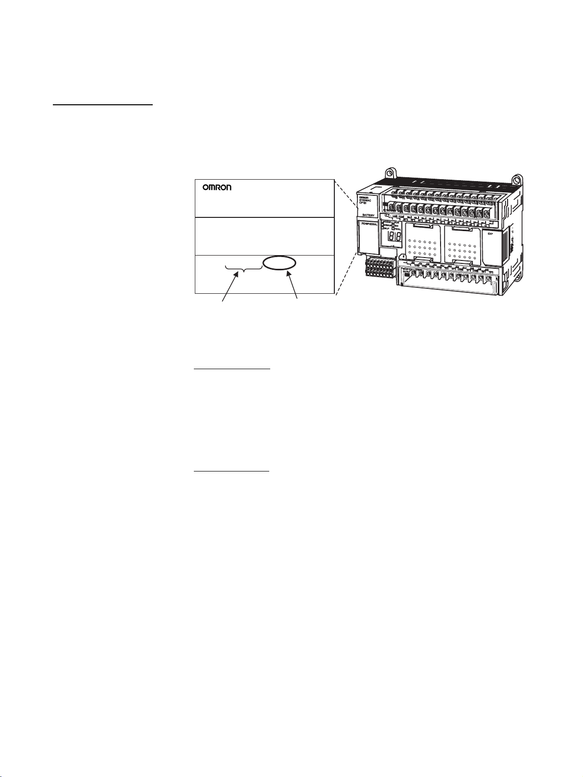
Unit Versions of CP-series CPU Units
Unit Versions A “unit version” has been introduced to manage CPU Units in the CP Series
according to differences in functionality accompanying Unit upgrades.
Notation of Unit Versions
on Products
Confirming Unit Versions
with Support Software
The unit version is given to the right of the lot number on the nameplate of the
products for which unit versions are being managed, as shown below.
Product nameplate
CP1H-XA40DR-A
CPU UNIT
Lot No. 28705 0000 Ver.1.0
OMRON Corporation MADE IN JAPAN
Lot No.
The methods used to confirm the unit version for the CP-series CP1H and
CP1L CPU Units are somewhat different.
CP1H CPU Units
CX-Programmer version 6.1 or higher can be used to confirm the unit version
using one of the following two methods. (See note.)
• Using the PLC Information
• Using the Unit Manufacturing Information
Unit version
(Example for Unit version 1.0)
CP-series CPU Unit
Note CX-Programmer versions lower than version 6.1 cannot be used to confirm
unit versions for CP1L CPU Units.
CP1L CPU Units
CX-Programmer version 7.1 or higher can be used to confirm the unit version
using the PLC Information. (See note.) The Unit Manufacturing Informa-
tion cannot be used.
Note CX-Programmer versions lower than version 7.1 cannot be used to confirm
unit versions for CP1L CPU Units.
vi
Page 6
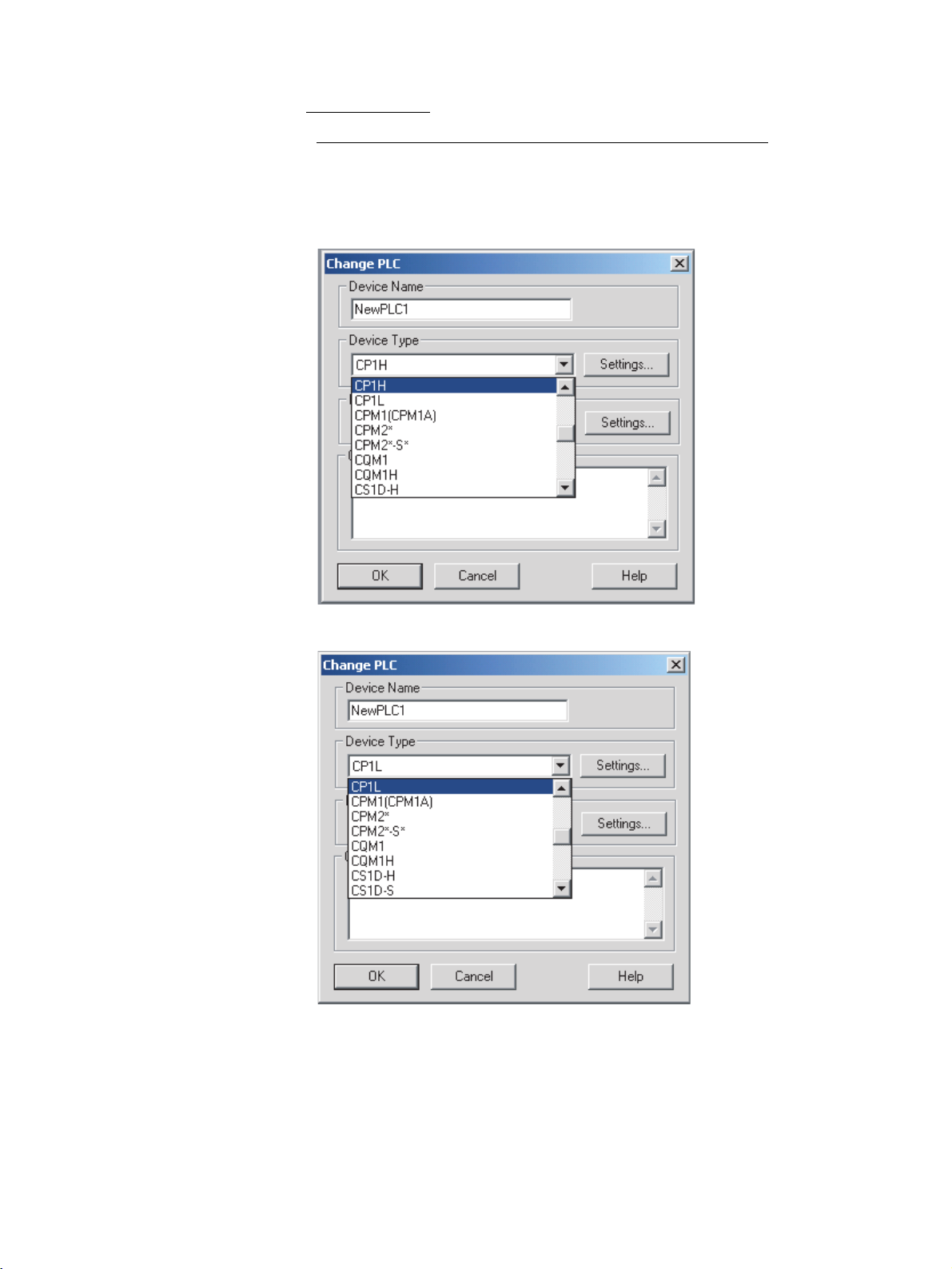
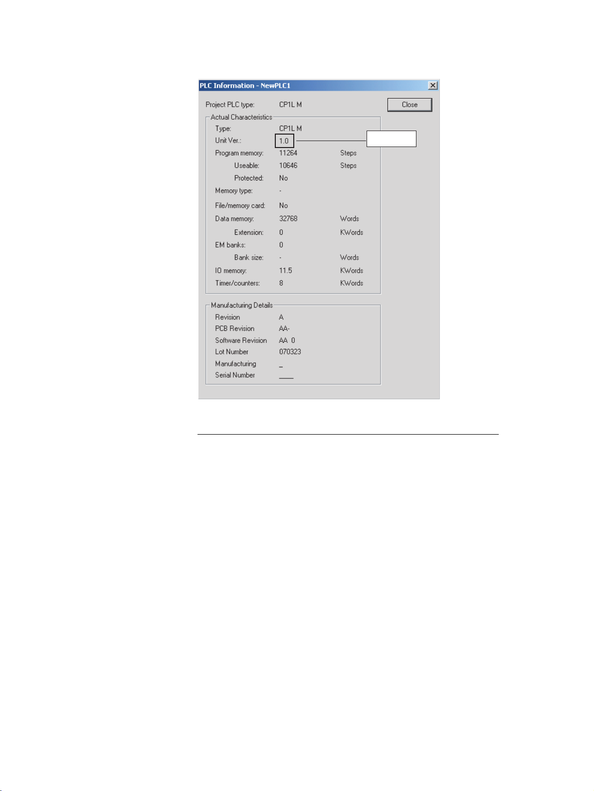
■ PLC Information
Procedure When the Device Type and CPU Type Are Known
1,2,3... 1. If you know the device type and CPU type, select them in the Change PLC
Dialog Box, go online, and select PLC - Edit - Information from the
menus. The following Change PLC Dialog Box will be displayed.
Example for CP1H
Example for CP1L
vii
Page 7
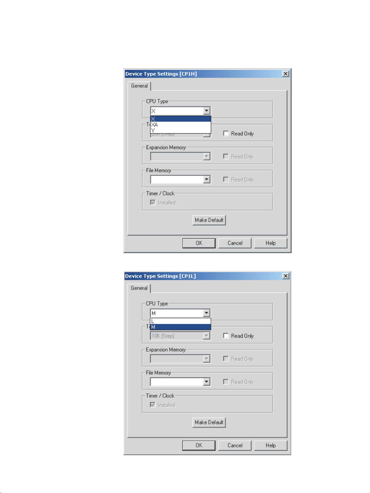
2. Click the Settings Button and, when the Device Type Settings Dialog Box
is displayed, select the CPU type.
Example for CP1H
Example for CP1L
viii
Page 8
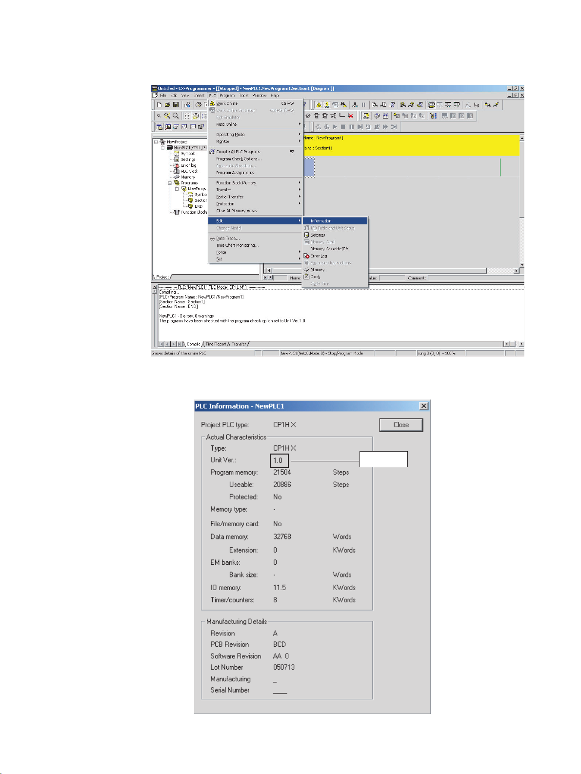
3. Go online and select PLC - Edit - Information
The PLC Information Dialog Box will be displayed.
Example for the CP1H
▲
Unit version
ix
Page 9
Example for the CP1L
▲
Unit version
Use the above display to confirm the unit version of the CPU Unit.
Procedure When the Device Type and CPU Type Are Not Known
This procedure is possible only when connected directly to the CPU Unit with
a serial connection.
If you don't know the device type and CPU type but are connected directly to
the CPU Unit on a serial line, select PLC - Auto Online to go online, and then
select PLC - Edit - Information from the menus.
The PLC Information Dialog Box will be displayed and can be used to confirm
the unit version of the CPU Unit.
x
Page 10
▲
Unit version
■ Unit Manufacturing Information (CP1H CPU Units Only)
1,2,3... 1. In the IO Table Window, right-click and select Unit Manufacturing infor-
mation - CPU Unit.
xi
Page 11
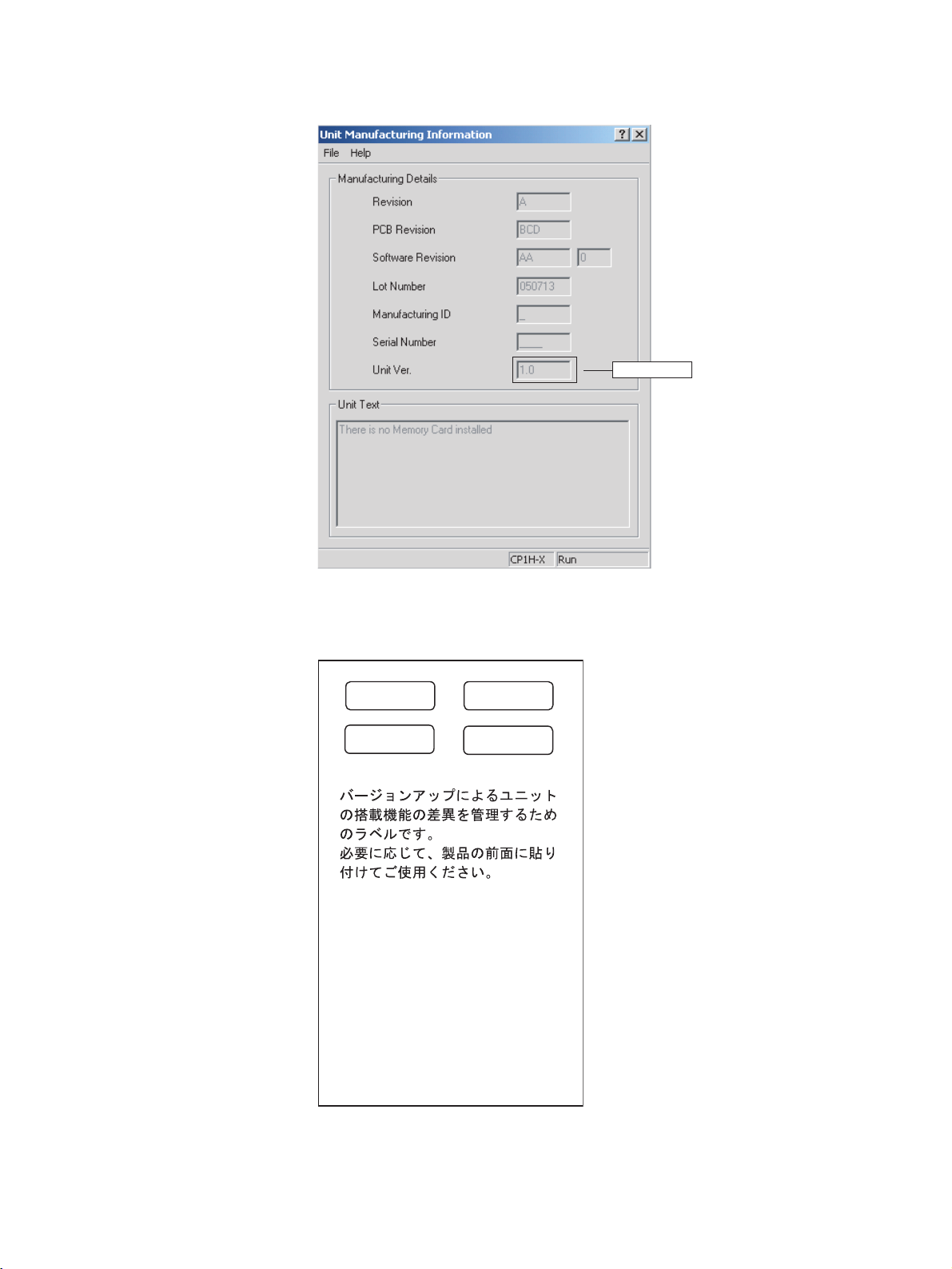
2. The following Unit Manufacturing information Dialog Box will be displayed.
Unit version
▲
Using the Unit Version
Labels
Use the above display to confirm the unit version of the CPU Unit connected
online.
The following unit version labels are provided with the CPU Unit.
Ver.
Ver.
Ver.
1.0
Ver.
1.0
These Labels can be
used to manage
differences in the
available functions
among the Units.
Place the appropriate
label on the front of
the Unit to show what
Unit version is actually
being used.
xii
These labels can be attached to the front of previous CPU Units to differentiate between CPU Units of different unit versions.
Page 12

TABLE OF CONTENTS
PRECAUTIONS . . . . . . . . . . . . . . . . . . . . . . . . . . . . . . . . . . . xxiii
1 Intended Audience. . . . . . . . . . . . . . . . . . . . . . . . . . . . . . . . . . . . . . . . . . . . . . . . . . . . . . . . . xxiv
2 General Precautions. . . . . . . . . . . . . . . . . . . . . . . . . . . . . . . . . . . . . . . . . . . . . . . . . . . . . . . . xxiv
3 Safety Precautions . . . . . . . . . . . . . . . . . . . . . . . . . . . . . . . . . . . . . . . . . . . . . . . . . . . . . . . . . xxiv
4 Operating Environment Precautions . . . . . . . . . . . . . . . . . . . . . . . . . . . . . . . . . . . . . . . . . . . xxvi
5 Application Precautions. . . . . . . . . . . . . . . . . . . . . . . . . . . . . . . . . . . . . . . . . . . . . . . . . . . . .xxvii
6 Conformance to EC Directives . . . . . . . . . . . . . . . . . . . . . . . . . . . . . . . . . . . . . . . . . . . . . . . xxx
SECTION 1
Programming Concepts . . . . . . . . . . . . . . . . . . . . . . . . . . . . . 1
1-1 Programming Concepts . . . . . . . . . . . . . . . . . . . . . . . . . . . . . . . . . . . . . . . . . . . . . . . . . . . . .2
1-2 Precautions . . . . . . . . . . . . . . . . . . . . . . . . . . . . . . . . . . . . . . . . . . . . . . . . . . . . . . . . . . . . . . 33
1-3 Checking Programs . . . . . . . . . . . . . . . . . . . . . . . . . . . . . . . . . . . . . . . . . . . . . . . . . . . . . . . . 41
1-4 Introducing Function Blocks . . . . . . . . . . . . . . . . . . . . . . . . . . . . . . . . . . . . . . . . . . . . . . . . . 46
SECTION 2
Tasks . . . . . . . . . . . . . . . . . . . . . . . . . . . . . . . . . . . . . . . . . . . . 49
2-1 Programming with Tasks . . . . . . . . . . . . . . . . . . . . . . . . . . . . . . . . . . . . . . . . . . . . . . . . . . .50
2-2 Using Tasks . . . . . . . . . . . . . . . . . . . . . . . . . . . . . . . . . . . . . . . . . . . . . . . . . . . . . . . . . . . . . . 58
2-3 Interrupt Tasks . . . . . . . . . . . . . . . . . . . . . . . . . . . . . . . . . . . . . . . . . . . . . . . . . . . . . . . . . . . . 68
2-4 CX-Programmer Operations for Tasks . . . . . . . . . . . . . . . . . . . . . . . . . . . . . . . . . . . . . . . . . 75
SECTION 3
Instructions. . . . . . . . . . . . . . . . . . . . . . . . . . . . . . . . . . . . . . . 77
3-1 Notation and Layout of Instruction Descriptions . . . . . . . . . . . . . . . . . . . . . . . . . . . . . . . . . 86
3-2 Sequence Input Instructions. . . . . . . . . . . . . . . . . . . . . . . . . . . . . . . . . . . . . . . . . . . . . . . . . .89
3-3 Sequence Output Instructions . . . . . . . . . . . . . . . . . . . . . . . . . . . . . . . . . . . . . . . . . . . . . . . . 113
3-4 Sequence Control Instructions. . . . . . . . . . . . . . . . . . . . . . . . . . . . . . . . . . . . . . . . . . . . . . . . 132
3-5 Timer and Counter Instructions . . . . . . . . . . . . . . . . . . . . . . . . . . . . . . . . . . . . . . . . . . . . . . . 168
3-6 Comparison Instructions . . . . . . . . . . . . . . . . . . . . . . . . . . . . . . . . . . . . . . . . . . . . . . . . . . . . 209
3-7 Data Movement Instructions . . . . . . . . . . . . . . . . . . . . . . . . . . . . . . . . . . . . . . . . . . . . . . . . . 247
3-8 Data Shift Instructions . . . . . . . . . . . . . . . . . . . . . . . . . . . . . . . . . . . . . . . . . . . . . . . . . . . . . . 274
3-9 Increment/Decrement Instructions. . . . . . . . . . . . . . . . . . . . . . . . . . . . . . . . . . . . . . . . . . . . . 320
3-10 Symbol Math Instructions . . . . . . . . . . . . . . . . . . . . . . . . . . . . . . . . . . . . . . . . . . . . . . . . . . .336
3-11 Conversion Instructions . . . . . . . . . . . . . . . . . . . . . . . . . . . . . . . . . . . . . . . . . . . . . . . . . . . . . 389
3-12 Logic Instructions . . . . . . . . . . . . . . . . . . . . . . . . . . . . . . . . . . . . . . . . . . . . . . . . . . . . . . . . . 436
3-13 Special Math Instructions . . . . . . . . . . . . . . . . . . . . . . . . . . . . . . . . . . . . . . . . . . . . . . . . . . . 451
3-14 Floating-point Math Instructions . . . . . . . . . . . . . . . . . . . . . . . . . . . . . . . . . . . . . . . . . . . . . . 472
3-15 Double-precision Floating-point Instructions . . . . . . . . . . . . . . . . . . . . . . . . . . . . . . . . . . . . 525
3-16 Table Data Processing Instructions . . . . . . . . . . . . . . . . . . . . . . . . . . . . . . . . . . . . . . . . . . . . 567
3-17 Data Control Instructions. . . . . . . . . . . . . . . . . . . . . . . . . . . . . . . . . . . . . . . . . . . . . . . . . . . . 615
xiii
Page 13

TABLE OF CONTENTS
3-18 Subroutines . . . . . . . . . . . . . . . . . . . . . . . . . . . . . . . . . . . . . . . . . . . . . . . . . . . . . . . . . . . . . . 668
3-19 Interrupt Control Instructions . . . . . . . . . . . . . . . . . . . . . . . . . . . . . . . . . . . . . . . . . . . . . . . . 692
3-20 High-speed Counter/Pulse Output Instructions . . . . . . . . . . . . . . . . . . . . . . . . . . . . . . . . . . . 705
3-21 Step Instructions . . . . . . . . . . . . . . . . . . . . . . . . . . . . . . . . . . . . . . . . . . . . . . . . . . . . . . . . . . 751
3-22 Basic I/O Unit Instructions . . . . . . . . . . . . . . . . . . . . . . . . . . . . . . . . . . . . . . . . . . . . . . . . . . 769
3-23 Serial Communications Instructions . . . . . . . . . . . . . . . . . . . . . . . . . . . . . . . . . . . . . . . . . . . 805
3-24 Network Instructions . . . . . . . . . . . . . . . . . . . . . . . . . . . . . . . . . . . . . . . . . . . . . . . . . . . . . . 844
3-25 Display Instructions. . . . . . . . . . . . . . . . . . . . . . . . . . . . . . . . . . . . . . . . . . . . . . . . . . . . . . . . 911
3-26 Clock Instructions . . . . . . . . . . . . . . . . . . . . . . . . . . . . . . . . . . . . . . . . . . . . . . . . . . . . . . . . . 918
3-27 Debugging Instructions . . . . . . . . . . . . . . . . . . . . . . . . . . . . . . . . . . . . . . . . . . . . . . . . . . . . . 932
3-28 Failure Diagnosis Instructions . . . . . . . . . . . . . . . . . . . . . . . . . . . . . . . . . . . . . . . . . . . . . . . .936
3-29 Other Instructions . . . . . . . . . . . . . . . . . . . . . . . . . . . . . . . . . . . . . . . . . . . . . . . . . . . . . . . . . 961
3-30 Block Programming Instructions. . . . . . . . . . . . . . . . . . . . . . . . . . . . . . . . . . . . . . . . . . . . . . 975
3-31 Text String Processing Instructions . . . . . . . . . . . . . . . . . . . . . . . . . . . . . . . . . . . . . . . . . . . . 1008
3-32 Task Control Instructions. . . . . . . . . . . . . . . . . . . . . . . . . . . . . . . . . . . . . . . . . . . . . . . . . . . . 1040
3-33 Model Conversion Instructions . . . . . . . . . . . . . . . . . . . . . . . . . . . . . . . . . . . . . . . . . . . . . . . 1047
SECTION 4
Instruction Execution Times and Number of Steps. . . . . . . 1065
4-1 Instruction Execution Times and Number of Steps. . . . . . . . . . . . . . . . . . . . . . . . . . . . . . . . 1066
4-2 Function Block Instance Execution Time . . . . . . . . . . . . . . . . . . . . . . . . . . . . . . . . . . . . . . . 1088
Appendices
A Instruction Classifications by Function . . . . . . . . . . . . . . . . . . . . . . . . . . . . . . . . . . . . . . . . 1091
B List of Instructions by Function Code . . . . . . . . . . . . . . . . . . . . . . . . . . . . . . . . . . . . . . . . . 1099
C Alphabetical List of Instructions by Mnemonic . . . . . . . . . . . . . . . . . . . . . . . . . . . . . . . . . . 1115
Index. . . . . . . . . . . . . . . . . . . . . . . . . . . . . . . . . . . . . . . . . . . . . 1129
Revision History . . . . . . . . . . . . . . . . . . . . . . . . . . . . . . . . . . . 1139
xiv
Page 14

About this Manual:
This manual describes programming the CP-series Programmable Controllers (PLCs) and includes
the sections described below. The CP1H and CP1L are advanced package-type PLCs based on
OMRON’s advanced control technologies and vast experience in automated control.
Please read this manual carefully and be sure you understand the information provided before
attempting to install or operate a CP1H or CP1L PLC. Be sure to read the precautions provided in the
following section.
Definition of the CP Series
The CP Series is centered around the CP1H and CP1L CPU Units and is designed with the same
basic architecture as the CS and CJ Series. The Special I/O Units and CPU Bus Units of the CJ Series
can thus be used with the CP1H CPU Units. CJ-series Basic I/O Units, however, cannot be used.
Always use CPM1A Expansion Units or CPM1A Expansion I/O Units when expanding the I/O capacity
of CP1H or CP1L PLCs.
I/O words are allocated in the same way as the CPM1A/CPM2A PLCs, i.e., using fixed areas for inputs
and outputs.
CS/CJ/CP Series
CS Series
CS1-H CPU Units
CS1H-CPU@@H
CS1G-CPU@@H
CS1 CPU Units
CS1H-CPU@@ (-V1)
CS1G-CPU@@ (-V1)
CS1D CPU Units
CS1D CPU Units for
Duplex-CPU System
CS1D-CPU
CS1D CPU Units for
Single-CPU System
CS1D-CPU S
CS1D Process CPU Units
CS1D-CPU
CS-series Basic I/O Units
CS-series Special I/O Units
CS-series CPU Bus Units
CS-series Power Supply Units
Note: Products specifically for the CS1D
Series are required to use CS1D
CPU Units.
@@H
@@
@@P
CJ Series
CJ1-H CPU Units
CJ1H-CPU@@H
CJ1G-CPU@@H
CJ1G -CPU@@P
(Loop CPU Unit)
CJ1M CPU Unit
CJ1M-CPU@@
CJ1 CPU Unit
CJ1G-CPU@@
CJ-series Basic I/O Units
CJ-series Special I/O Units
CJ-series CPU Bus Units
CJ-series Power Supply Units
CP Series
CP1H CPU Units
CP1H-X@@@@-@
CP1H-XA@@@@-@
CP1H-Y@@@@-@
CP1L CPU Unit
CP1L-L14D@-@
CP1L-L20D@-@
CP1L-M30D@-@
CP1L-M40D@-@
CP-series Expansion I/O Units
CP-series Expansion Units
CPM1A Expansion I/O Units
CPM1A Expansion Units
CJ-series Special I/O Units (See note.)
CJ-series CPU Bus Units (See note.)
Note: Can be used with only a CP1H
CPU Unit.
xv
Page 15

Precautions provides general precautions for using the Programmable Controller and related devices.
Section 1 describes the basic concepts required to program the CP1H.
Section 2 describes the operation of tasks and how to use tasks in programming.
Section 3 describes each of the instructions that can be used in programming CP-series PLCs.
Instructions are described in order of function.
Section 4 lists the execution times and number of steps for all instructions supported by the CP1H
PLCs, and describes the execution times for function block instances.
The Appendices provide lists of the programming instructions in order of function and in order of function number.
xvi
Page 16

Related Manuals
The following manuals are used for the CP-series CPU Units. Refer to these manuals as required.
Cat. No. Model numbers Manual name Description
W451 CP1H-X40D@-@
CP1H-XA40D@-@
CP1H-Y20DT-D
CP1L-L14D@-@
CP1L-L20D@-@
CP1L-M30D@-@
CP1L-M40D@-@
W450 CP1H-X40D@-@
CP1H-XA40D@-@
CP1H-Y20DT-D
W462 CP1L-L14D@-@
CP1L-L20D@-@
CP1L-M30D@-@
CP1L-M40D@-@
W461 CP1L-L14D@-@
CP1L-L20D@-@
CP1L-M30D@-@
CP1L-M40D@-@
W342 CS1G/H-CPU@@H
CS1G/H-CPU@@-V1
CS1D-CPU@@H
CS1D-CPU@@S
CS1W-SCU21
CS1W-SCB21-V1/41-V1
CJ1G/H-CPU@@H
CJ1G-CPU@@P
CP1H-CPU@@
CJ1G-CPU@@
CJ1W-SCU21-V1/41-V1
W446 WS02-CXPC1-E-V70 SYSMAC CX-Pro-
W447 WS02-CXPC1-E-V70 SYSMAC CX-Pro-
W444 CXONE-AL@@C-E CX-One FA Inte-
SYSMAC CP Series
CP1H and CP1L CPU
Unit Programming
Manual
(This manual)
SYSMAC CP Series
CP1H CPU Unit
Operation Manual
SYSMAC CP Series
CP1L CPU Unit Operation Manual
SYSMAC CP Series
CP1L Introduction
Manual
SYSMAC CS/CJseries Communications Commands Reference Manual
grammer
Ver. 7.0 Operation
Manual
grammer Ver. 7.0
Operation Manual
Function Blocks
grated Tool Package
Setup Manual
Provides the following information on the CP Series:
• Programming instructions
• Programming methods
•Tasks
• File memory
• Functions
Use this manual together with the CP Series CP1H
CPU Units Operation Manual (W450) and CP
Series CP1L CPU Units Operation Manual (W462)
Provide the following information on the CP Series:
• Overview, design, installation, maintenance, and
other basic specifications
•Features
• System configuration
• Mounting and wiring
• I/O memory allocation
• Troubleshooting
Use this manual together with the CP1H Program-
mable Controllers Programming Manual (W451).
Provides basic setup information for CP1L PLCs,
including the following.
• Basic configuration and part names
• Mounting and wiring procedures
• Programming, program transfer, and debugging
with the CX-Programmer
• Application programming examples using the
CP1L
Describes commands addressed to CS-series, and
CJ-series CPU Units, including C-mode commands
and FINS commands.
Note This manual describes on commands
address to CPU Units regardless of the communications path. (CPU Unit serial ports,
Serial Communications Unit/Board ports, and
Communications Unit ports can be used.)
Refer to the relevant operation manuals for
information on commands addresses to Special I/O Units and CPU Bus Units.
Provides information on installing and operating the
CX-Programmer for all functions except for function
blocks.
Provides specifications and operating procedures
for function blocks. Function blocks can be used
with CX-Programmer Ver. 6.1 or higher and either a
CS1-H/CJ1-H CPU Unit with a unit version of 3.0 or
a CP1H CPU Unit. Refer to W446 for operating procedures for functions other than function blocks.
Provides an overview of the CX-One FA Integrated
Tool and installation procedures.
xvii
Page 17

Cat. No. Model numbers Manual name Description
W445 CXONE-AL@@C-E CX-Integrator Opera-
tion Manual
W344 WS02-PSTC1-E CX-Protocol Opera-
tion Manual
Describes CX-Integrator operating procedures and
provides information on network configuration (data
links, routing tables, Communications Units setup,
etc.
Provides operating procedures for creating protocol
macros (i.e., communications sequences) with the
CX-Protocol and other information on protocol macros.
The CX-Protocol is required to create protocol macros for user-specific serial communications or to
customize the standard system protocols.
xviii
Page 18

Read and Understand this Manual
Please read and understand this manual before using the product. Please consult your OMRON
representative if you have any questions or comments.
Warranty and Limitations of Liability
WARRANTY
OMRON's exclusive warranty is that the products are free from defects in materials and workmanship for a
period of one year (or other period if specified) from date of sale by OMRON.
OMRON MAKES NO WARRANTY OR REPRESENTATION, EXPRESS OR IMPLIED, REGARDING NONINFRINGEMENT, MERCHANTABILITY, OR FITNESS FOR PARTICULAR PURPOSE OF THE
PRODUCTS. ANY BUYER OR USER ACKNOWLEDGES THAT THE BUYER OR USER ALONE HAS
DETERMINED THAT THE PRODUCTS WILL SUITABLY MEET THE REQUIREMENTS OF THEIR
INTENDED USE. OMRON DISCLAIMS ALL OTHER WARRANTIES, EXPRESS OR IMPLIED.
LIMITATIONS OF LIABILITY
OMRON SHALL NOT BE RESPONSIBLE FOR SPECIAL, INDIRECT, OR CONSEQUENTIAL DAMAGES,
LOSS OF PROFITS OR COMMERCIAL LOSS IN ANY WAY CONNECTED WITH THE PRODUCTS,
WHETHER SUCH CLAIM IS BASED ON CONTRACT, WARRANTY, NEGLIGENCE, OR STRICT
LIABILITY.
In no event shall the responsibility of OMRON for any act exceed the individual price of the product on which
liability is asserted.
IN NO EVENT SHALL OMRON BE RESPONSIBLE FOR WARRANTY, REPAIR, OR OTHER CLAIMS
REGARDING THE PRODUCTS UNLESS OMRON'S ANALYSIS CONFIRMS THAT THE PRODUCTS
WERE PROPERLY HANDLED, STORED, INSTALLED, AND MAINTAINED AND NOT SUBJECT TO
CONTAMINATION, ABUSE, MISUSE, OR INAPPROPRIATE MODIFICATION OR REPAIR.
xix
Page 19

Application Considerations
SUITABILITY FOR USE
OMRON shall not be responsible for conformity with any standards, codes, or regulations that apply to the
combination of products in the customer's application or use of the products.
At the customer's request, OMRON will provide applicable third party certification documents identifying
ratings and limitations of use that apply to the products. This information by itself is not sufficient for a
complete determination of the suitability of the products in combination with the end product, machine,
system, or other application or use.
The following are some examples of applications for which particular attention must be given. This is not
intended to be an exhaustive list of all possible uses of the products, nor is it intended to imply that the uses
listed may be suitable for the products:
• Outdoor use, uses involving potential chemical contamination or electrical interference, or conditions or
uses not described in this manual.
• Nuclear energy control systems, combustion systems, railroad systems, aviation systems, medical
equipment, amusement machines, vehicles, safety equipment, and installations subject to separate
industry or government regulations.
• Systems, machines, and equipment that could present a risk to life or property.
Please know and observe all prohibitions of use applicable to the products.
NEVER USE THE PRODUCTS FOR AN APPLICATION INVOLVING SERIOUS RISK TO LIFE OR
PROPERTY WITHOUT ENSURING THAT THE SYSTEM AS A WHOLE HAS BEEN DESIGNED TO
ADDRESS THE RISKS, AND THAT THE OMRON PRODUCTS ARE PROPERLY RATED AND INSTALLED
FOR THE INTENDED USE WITHIN THE OVERALL EQUIPMENT OR SYSTEM.
PROGRAMMABLE PRODUCTS
OMRON shall not be responsible for the user's programming of a programmable product, or any
consequence thereof.
xx
Page 20

Disclaimers
CHANGE IN SPECIFICATIONS
Product specifications and accessories may be changed at any time based on improvements and other
reasons.
It is our practice to change model numbers when published ratings or features are changed, or when
significant construction changes are made. However, some specifications of the products may be changed
without any notice. When in doubt, special model numbers may be assigned to fix or establish key
specifications for your application on your request. Please consult with your OMRON representative at any
time to confirm actual specifications of purchased products.
DIMENSIONS AND WEIGHTS
Dimensions and weights are nominal and are not to be used for manufacturing purposes, even when
tolerances are shown.
PERFORMANCE DATA
Performance data given in this manual is provided as a guide for the user in determining suitability and does
not constitute a warranty. It may represent the result of OMRON's test conditions, and the users must
correlate it to actual application requirements. Actual performance is subject to the OMRON Warranty and
Limitations of Liability.
ERRORS AND OMISSIONS
The information in this manual has been carefully checked and is believed to be accurate; however, no
responsibility is assumed for clerical, typographical, or proofreading errors, or omissions.
xxi
Page 21

xxii
Page 22

PRECAUTIONS
This section provides general precautions for using the CP-series Programmable Controllers (PLCs) and related devices.
The information contained in this section is important for the safe and reliable application of Programmable
Controllers. You must read this section and understand the information contained before attempting to set up or
operate a PLC system.
1 Intended Audience . . . . . . . . . . . . . . . . . . . . . . . . . . . . . . . . . . . . . . . . . . . . . xxiv
2 General Precautions . . . . . . . . . . . . . . . . . . . . . . . . . . . . . . . . . . . . . . . . . . . . xxiv
3 Safety Precautions. . . . . . . . . . . . . . . . . . . . . . . . . . . . . . . . . . . . . . . . . . . . . . xxiv
4 Operating Environment Precautions . . . . . . . . . . . . . . . . . . . . . . . . . . . . . . . . xxvi
5 Application Precautions . . . . . . . . . . . . . . . . . . . . . . . . . . . . . . . . . . . . . . . . . xxvii
6 Conformance to EC Directives . . . . . . . . . . . . . . . . . . . . . . . . . . . . . . . . . . . . xxx
6-1 Applicable Directives . . . . . . . . . . . . . . . . . . . . . . . . . . . . . . . . . . . . xxx
6-2 Concepts . . . . . . . . . . . . . . . . . . . . . . . . . . . . . . . . . . . . . . . . . . . . . . xxx
6-3 Conformance to EC Directives . . . . . . . . . . . . . . . . . . . . . . . . . . . . . xxx
6-4 Relay Output Noise Reduction Methods . . . . . . . . . . . . . . . . . . . . . xxxi
6-5 Conditions for Meeting EMC Directives when Using CP1,
CP-series, or CPM1A Relay Expansion I/O Units. . . . . . . . . . . . . . xxxii
xxiii
Page 23

Intended Audience 1
1 Intended Audience
This manual is intended for the following personnel, who must also have
knowledge of electrical systems (an electrical engineer or the equivalent).
• Personnel in charge of installing FA systems.
• Personnel in charge of designing FA systems.
• Personnel in charge of managing FA systems and facilities.
2 General Precautions
The user must operate the product according to the performance specifications described in the operation manuals.
Before using the product under conditions which are not described in the
manual or applying the product to nuclear control systems, railroad systems,
aviation systems, vehicles, combustion systems, medical equipment, amusement machines, safety equipment, and other systems, machines, and equipment that may have a serious influence on lives and property if used
improperly, consult your OMRON representative.
Make sure that the ratings and performance characteristics of the product are
sufficient for the systems, machines, and equipment, and be sure to provide
the systems, machines, and equipment with double safety mechanisms.
This manual provides information for programming and operating the Unit. Be
sure to read this manual before attempting to use the Unit and keep this manual close at hand for reference during operation.
!WARNING It is extremely important that a PLC and all PLC Units be used for the speci-
fied purpose and under the specified conditions, especially in applications that
can directly or indirectly affect human life. You must consult with your OMRON
representative before applying a PLC System to the above-mentioned applications.
3 Safety Precautions
!WARNING Do not attempt to take any Unit apart while the power is being supplied. Doing
so may result in electric shock.
!WARNING Do not touch any of the terminals or terminal blocks while the power is being
supplied. Doing so may result in electric shock.
!WARNING Do not attempt to disassemble, repair, or modify any Units. Any attempt to do
so may result in malfunction, fire, or electric shock.
!WARNING Provide safety measures in external circuits (i.e., not in the Programmable
Controller), including the following items, to ensure safety in the system if an
abnormality occurs due to malfunction of the PLC or another external factor
affecting the PLC operation. Not doing so may result in serious accidents.
xxiv
• Emergency stop circuits, interlock circuits, limit circuits, and similar safety
measures must be provided in external control circuits.
Page 24

Safety Precautions 3
• The PLC will turn OFF all outputs when its self-diagnosis function detects
any error or when a severe failure alarm (FALS) instruction is executed.
As a countermeasure for such errors, external safety measures must be
provided to ensure safety in the system.
• The PLC or outputs may remain ON or OFF due to deposits on or burning
of the output relays, or destruction of the output transistors. As a countermeasure for such problems, external safety measures must be provided
to ensure safety in the system.
• When the 24-V DC output (service power supply to the PLC) is overloaded or short-circuited, the voltage may drop and result in the outputs
being turned OFF. As a countermeasure for such problems, external
safety measures must be provided to ensure safety in the system.
!WARNING Fail-safe measures must be taken by the customer to ensure safety in the
event of incorrect, missing, or abnormal signals caused by broken signal lines,
momentary power interruptions, or other causes. Not doing so may result in
serious accidents.
!Caution Execute online edit only after confirming that no adverse effects will be
caused by extending the cycle time. Otherwise, the input signals may not be
readable.
!Caution Confirm safety at the destination node before transferring a program to
another node or editing the I/O area. Doing either of these without confirming
safety may result in injury.
!Caution Tighten the screws on the terminal block of the AC Power Supply Unit to the
torque specified in this manual. The loose screws may result in burning or
malfunction.
!Caution Do not touch anywhere near the power supply parts or I/O terminals while the
power is ON, and immediately after turning OFF the power. The hot surface
may cause burn injury.
!Caution Pay careful attention to the polarities (+/-) when wiring the DC power supply. A
wrong connection may cause malfunction of the system.
!Caution When connecting the PLC to a computer or other peripheral device, either
ground the 0 V side of the external power supply or do not ground the external
power supply at all. Otherwise the external power supply may be shorted
depending on the connection methods of the peripheral device. DO NOT
ground the 24 V side of the external power supply, as shown in the following
diagram.
Non-insulated DC power supply
24 V
Twisted-pair
cable
FG
0 V
0 V
CPU Unit
FG
FG
0 V
Peripheral device
FG
xxv
Page 25

Operating Environment Precautions 4
!Caution After programming (or reprogramming) using the IOWR instruction, confirm
that correct operation is possible with the new ladder program and data before
starting actual operation. Any irregularities may cause the product to stop
operating, resulting in unexpected operation in machinery or equipment.
!Caution The CP-series CPU Units automatically back up the user program and param-
eter data to flash memory when these are written to the CPU Unit. I/O memory (including the DM Area, Counter present values and Completion Flags,
and HR Area), however, is not written to flash memory. The DM Area, Counter
present values and Completion Flags, and HR Area can be held during power
interruptions with a battery. If there is a battery error, the contents of these
areas may not be accurate after a power interruption. If the contents of the
DM Area, Counter present values and Completion Flags, and HR Area are
used to control external outputs, prevent inappropriate outputs from being
made whenever the Battery Error Flag (A402.04) is ON.
4 Operating Environment Precautions
!Caution Do not operate the control system in the following locations:
• Locations subject to direct sunlight.
• Locations subject to temperatures or humidity outside the range specified
in the specifications.
• Locations subject to condensation as the result of severe changes in temperature.
• Locations subject to corrosive or flammable gases.
• Locations subject to dust (especially iron dust) or salts.
• Locations subject to exposure to water, oil, or chemicals.
• Locations subject to shock or vibration.
!Caution Take appropriate and sufficient countermeasures when installing systems in
the following locations:
• Locations subject to static electricity or other forms of noise.
• Locations subject to strong electromagnetic fields.
• Locations subject to possible exposure to radioactivity.
• Locations close to power supplies.
!Caution The operating environment of the PLC System can have a large effect on the
longevity and reliability of the system. Improper operating environments can
lead to malfunction, failure, and other unforeseeable problems with the PLC
System. Make sure that the operating environment is within the specified conditions at installation and remains within the specified conditions during the
life of the system.
xxvi
Page 26

Application Precautions 5
5 Application Precautions
Observe the following precautions when using the PLC System.
!WARNING Always heed these precautions. Failure to abide by the following precautions
could lead to serious or possibly fatal injury.
• Always connect to 100
to a ground of 100
• Always turn OFF the power supply to the PLC before attempting any of
the following. Not turning OFF the power supply may result in malfunction
or electric shock.
• Mounting or dismounting Expansion Units or any other Units
• Connecting or removing the Memory Cassette or Option Board
• Setting DIP switches or rotary switches
• Connecting or wiring the cables
• Connecting or disconnecting the connectors
!Caution Failure to abide by the following precautions could lead to faulty operation of
the PLC or the system, or could damage the PLC or PLC Units. Always heed
these precautions.
• Install external breakers and take other safety measures against short-circuiting in external wiring. Insufficient safety measures against short-circuiting may result in burning.
• Mount the Unit only after checking the connectors and terminal blocks
completely.
• Be sure that all the terminal screws and cable connector screws are tightened to the torque specified in the relevant manuals. Incorrect tightening
torque may result in malfunction.
• Wire all connections correctly according to instructions in this manual.
• Always use the power supply voltage specified in the operation manuals.
An incorrect voltage may result in malfunction or burning.
• Take appropriate measures to ensure that the specified power with the
rated voltage and frequency is supplied. Be particularly careful in places
where the power supply is unstable. An incorrect power supply may result
in malfunction.
• Leave the label attached to the Unit when wiring. Removing the label may
result in malfunction.
• Remove the label after the completion of wiring to ensure proper heat dissipation. Leaving the label attached may result in malfunction.
• Use crimp terminals for wiring. Do not connect bare stranded wires
directly to terminals. Connection of bare stranded wires may result in
burning.
• Do not apply voltages to the input terminals in excess of the rated input
voltage. Excess voltages may result in burning.
• Do not apply voltages or connect loads to the output terminals in excess
of the maximum switching capacity. Excess voltage or loads may result in
burning.
Ω or less when installing the Units. Not connecting
Ω or less may result in electric shock.
xxvii
Page 27

Application Precautions 5
• Be sure that the terminal blocks, connectors, Option Boards, and other
items with locking devices are properly locked into place. Improper locking
may result in malfunction.
• Disconnect the functional ground terminal when performing withstand
voltage tests. Not disconnecting the functional ground terminal may result
in burning.
• Wire correctly and double-check all the wiring or the setting switches
before turning ON the power supply. Incorrect wiring may result in burning.
• Check that the DIP switches and data memory (DM) are properly set
before starting operation.
• Check the user program for proper execution before actually running it on
the Unit. Not checking the program may result in an unexpected operation.
• Resume operation only after transferring to the new CPU Unit and/or Special I/O Units the contents of the DM, HR, and CNT Areas required for
resuming operation. Not doing so may result in an unexpected operation.
• Confirm that no adverse effect will occur in the system before attempting
any of the following. Not doing so may result in an unexpected operation.
• Changing the operating mode of the PLC (including the setting of the
startup operating mode).
• Force-setting/force-resetting any bit in memory.
• Changing the present value of any word or any set value in memory.
• Do not pull on the cables or bend the cables beyond their natural limit.
Doing either of these may break the cables.
• Do not place objects on top of the cables. Doing so may break the cables.
• When replacing parts, be sure to confirm that the rating of a new part is
correct. Not doing so may result in malfunction or burning.
• Before touching the Unit, be sure to first touch a grounded metallic object
in order to discharge any static buildup. Not doing so may result in malfunction or damage.
• Do not touch the Expansion I/O Unit Connecting Cable while the power is
being supplied in order to prevent malfunction due to static electricity.
• Do not turn OFF the power supply to the Unit while data is being transferred.
• When transporting or storing the product, cover the PCBs with electrically
conductive materials to prevent LSIs and ICs from being damaged by
static electricity, and also keep the product within the specified storage
temperature range.
• Do not touch the mounted parts or the rear surface of PCBs because
PCBs have sharp edges such as electrical leads.
• Double-check the pin numbers when assembling and wiring the connectors.
• Wire correctly according to specified procedures.
• Do not connect pin 6 (+5V) on the RS-232C Option Board on the CPU
Unit to any external device other than the NT-AL001 or CJ1W-CIF11 Conversion Adapter. The external device and the CPU Unit may be damaged.
• Use the dedicated connecting cables specified in this manual to connect
the Units. Using commercially available RS-232C computer cables may
cause failures in external devices or the CPU Unit.
xxviii
Page 28

Application Precautions 5
• Check that data link tables and parameters are properly set before starting operation. Not doing so may result in unexpected operation. Even if
the tables and parameters are properly set, confirm that no adverse
effects will occur in the system before running or stopping data links.
• Transfer a routing table to the CPU Unit only after confirming that no
adverse effects will be caused by restarting CPU Bus Units, which is automatically done to make the new tables effective.
• The user program and parameter area data in the CP-series CPU Unit is
backed up in the built-in flash memory. The BKUP indicator will light on
the front of the CPU Unit when the backup operation is in progress. Do
not turn OFF the power supply to the CPU Unit when the BKUP indicator
is lit. The data will not be backed up if power is turned OFF.
• Do not turn OFF the power supply to the PLC while the Memory Cassette
is being written. Doing so may corrupt the data in the Memory Cassette.
The BKUP indicator will light while the Memory Cassette is being written.
With a CP1H CPU Unit, the 7-segment display will also light to indicate
writing progress. Wait for the BKUP indicator and 7-segment display to go
out before turning OFF the power supply to the PLC.
• Before replacing the battery, supply power to the CPU Unit for at least 5
minutes and then complete battery replacement within 5 minutes of turn
OFF the power supply. Memory data may be corrupted if this precaution is
not observed.
• Always use the following size wire when connecting I/O Units, Special I/O
Units, and CPU Bus Units: AWG22 to AWG18 (0.32 to 0.82 mm
• UL standards required that batteries be replaced only by experienced
technicians. Do not allow unqualified persons to replace batteries. Also,
always follow the replacement procedure provided in the manual.
• Never short-circuit the positive and negative terminals of a battery or
charge, disassemble, heat, or incinerate the battery. Do not subject the
battery to strong shocks or deform the barry by applying pressure. Doing
any of these may result in leakage, rupture, heat generation, or ignition of
the battery. Dispose of any battery that has been dropped on the floor or
otherwise subjected to excessive shock. Batteries that have been subjected to shock may leak if they are used.
• Always construct external circuits so that the power to the PLC it turned
ON before the power to the control system is turned ON. If the PLC power
supply is turned ON after the control power supply, temporary errors may
result in control system signals because the output terminals on DC Output Units and other Units will momentarily turn ON when power is turned
ON to the PLC.
• Fail-safe measures must be taken by the customer to ensure safety in the
event that outputs from Output Units remain ON as a result of internal circuit failures, which can occur in relays, transistors, and other elements.
• If the I/O Hold Bit is turned ON, the outputs from the PLC will not be
turned OFF and will maintain their previous status when the PLC is
switched from RUN or MONITOR mode to PROGRAM mode. Make sure
that the external loads will not produce dangerous conditions when this
occurs. (When operation stops for a fatal error, including those produced
with the FALS(007) instruction, all outputs from Output Unit will be turned
OFF and only the internal output status will be maintained.)
2
).
xxix
Page 29

Conformance to EC Directives 6
• Dispose of the product and batteries according to local ordinances as
they apply.
Have qualified specialists properly dispose of used batteries as industrial
waste.
6 Conformance to EC Directives
6-1 Applicable Directives
•EMC Directives
• Low Voltage Directive
6-2 Concepts
EMC Directives
OMRON devices that comply with EC Directives also conform to the related
EMC standards so that they can be more easily built into other devices or the
overall machine. The actual products have been checked for conformity to
EMC standards (see the following note). Whether the products conform to the
standards in the system used by the customer, however, must be checked by
the customer.
EMC-related performance of the OMRON devices that comply with EC Directives will vary depending on the configuration, wiring, and other conditions of
the equipment or control panel on which the OMRON devices are installed.
The customer must, therefore, perform the final check to confirm that devices
and the overall machine conform to EMC standards.
Note The applicable EMC (Electromagnetic Compatibility) standard is EN61131-2.
Low Voltage Directive
Always ensure that devices operating at voltages of 50 to 1,000 V AC and 75
to 1,500 V DC meet the required safety standards for the PLC (EN61131-2).
6-3 Conformance to EC Directives
The CP1H/CP1L PLCs comply with EC Directives. To ensure that the
machine or device in which the CP1H/CP1L PLC is used complies with EC
Directives, the PLC must be installed as follows:
1,2,3... 1. The CP1H/CP1L PLC must be installed within a control panel.
2. You must use reinforced insulation or double insulation for the DC power
supplies used for I/O Units and CPU Units requiring DC power. The output
holding time must be 10 ms minimum for the DC power supply connected
to the power supply terminals on Units requiring DC power.
3. CP1H/CP1L PLCs complying with EC Directives also conform to
EN61131-2. Radiated emission characteristics (10-m regulations) may
vary depending on the configuration of the control panel used, other devices connected to the control panel, wiring, and other conditions. You must
therefore confirm that the overall machine or equipment complies with EC
Directives.
xxx
Page 30

Conformance to EC Directives 6
6-4 Relay Output Noise Reduction Methods
The CP1H/CP1L PLCs conforms to the Common Emission Standards
(EN61131-2) of the EMC Directives. However, noise generated by relay output switching may not satisfy these Standards. In such a case, a noise filter
must be connected to the load side or other appropriate countermeasures
must be provided external to the PLC.
Countermeasures taken to satisfy the standards vary depending on the
devices on the load side, wiring, configuration of machines, etc. Following are
examples of countermeasures for reducing the generated noise.
Countermeasures
Countermeasures are not required if the frequency of load switching for the
whole system with the PLC included is less than 5 times per minute.
Countermeasures are required if the frequency of load switching for the whole
system with the PLC included is more than 5 times per minute.
Note Refer to EN61131-2 for more details.
Countermeasure Examples
When switching an inductive load, connect an surge protector, diodes, etc., in
parallel with the load or contact as shown below.
Circuit Current Characteristic Required element
CR method
Powe r
supply
AC DC
Yes Yes If the load is a relay or solenoid, there is
C
R
Inductive
load
a time lag between the moment the circuit is opened and the moment the load
is reset.
If the supply voltage is 24 or 48 V, insert
the surge protector in parallel with the
load. If the supply voltage is 100 to
200 V, insert the surge protector
between the contacts.
The capacitance of the capacitor must
be 1 to 0.5 µF per contact current of
1 A and resistance of the resistor must
be 0.5 to 1 Ω per contact voltage of 1 V.
These values, however, vary with the
load and the characteristics of the
relay. Decide these values from experiments, and take into consideration that
the capacitance suppresses spark discharge when the contacts are separated and the resistance limits the
current that flows into the load when
the circuit is closed again.
The dielectric strength of the capacitor
must be 200 to 300 V. If the circuit is an
AC circuit, use a capacitor with no
polarity.
xxxi
Page 31

Conformance to EC Directives 6
Circuit Current Characteristic Required element
AC DC
Diode method
Powe r
supply
Varistor method
Power
supply
No Yes The diode connected in parallel with
the load changes energy accumulated
by the coil into a current, which then
flows into the coil so that the current will
be converted into Joule heat by the
Inductive
load
resistance of the inductive load.
This time lag, between the moment the
circuit is opened and the moment the
load is reset, caused by this method is
longer than that caused by the CR
method.
Yes Yes The varistor method prevents the impo-
sition of high voltage between the contacts by using the constant voltage
characteristic of the varistor. There is
time lag between the moment the cir-
Inductive
load
cuit is opened and the moment the load
is reset.
If the supply voltage is 24 or 48 V, insert
the varistor in parallel with the load. If
the supply voltage is 100 to 200 V,
insert the varistor between the contacts.
The reversed dielectric strength value
of the diode must be at least 10 times
as large as the circuit voltage value.
The forward current of the diode must
be the same as or larger than the load
current.
The reversed dielectric strength value
of the diode may be two to three times
larger than the supply voltage if the
surge protector is applied to electronic
circuits with low circuit voltages.
---
When switching a load with a high inrush current such as an incandescent
lamp, suppress the inrush current as shown below.
Countermeasure 1
OUT
R
COM
Providing a dark current of
approx. one-third of the rated
value through an incandescent
lamp
Countermeasure 2
R
OUT
COM
Providing a limiting resistor
6-5 Conditions for Meeting EMC Directives when Using CP1, CP-
series, or CPM1A Relay Expansion I/O Units
EN 61131-2 immunity testing conditions when using the CP1W-40EDR,
CPM1A-40EDR, CP1W-16ER or CPM1A-16ER with an CP1W-CN811 I/O
Connecting Cable are given below.
Recommended Ferrite Core
Ferrite Core (Data Line Filter): 0443-164151 manufactured by Nisshin Electric
Minimum impedance: 90 Ω at 25 MHz, 160 Ω at 100 MHz
xxxii
30
32 33
Page 32

Conformance to EC Directives 6
Recommended Connection Method
1,2,3... 1. Cable Connection Method
2. Connection Method
As shown below, connect a ferrite core to each end of the CP1W-CN811
I/O Connecting Cable.
SYSMAC
IN
CP1H
AC100-240V
L1 L2/N COM 01 03 05 07 09 11 01 03 05 07 09 11
BATTERY
00 02 04 06 08 10 00 02 04 06 08 10
POWER
PERIPHERAL
ERR/ALM
BKUP
MEMORY
00 01 02 03 04 06 00 01 03 04 06
COM COM COM COM 05 07 COM 02 COM 05 07
100CH 101CH
OUT
EXP
1CH
NCNCNC
COM
01 03 05 07 09 11 01 03 05 07 09 11
NC
00 02 04 06 08 10
CH CH
CH
IN
CH
CH
0706050403020100
OUT
CH
0706050403020100
CH CH
NC
00 01 02 04 05 07 00 02 04 05 07
NC
COM COM COM COM COM COM03 06 01 03 06
111009080706050403020100
111009080706050403020100
00 02 04 06 08 10
40EDR
EXP
xxxiii
Page 33

Conformance to EC Directives 6
xxxiv
Page 34

Programming Concepts
This section describes the basic concepts required to program the CP1H.
1-1 Programming Concepts. . . . . . . . . . . . . . . . . . . . . . . . . . . . . . . . . . . . . . . . . . 2
1-1-1 Programs and Tasks . . . . . . . . . . . . . . . . . . . . . . . . . . . . . . . . . . . . . 2
1-1-2 Basic Information on Instructions . . . . . . . . . . . . . . . . . . . . . . . . . . 4
1-1-3 Instruction Location and Execution Conditions . . . . . . . . . . . . . . . . 6
1-1-4 Addressing I/O Memory Areas. . . . . . . . . . . . . . . . . . . . . . . . . . . . . 7
1-1-5 Specifying Instruction Operands . . . . . . . . . . . . . . . . . . . . . . . . . . . 8
1-1-6 Data Formats. . . . . . . . . . . . . . . . . . . . . . . . . . . . . . . . . . . . . . . . . . . 13
1-1-7 Instruction Variations . . . . . . . . . . . . . . . . . . . . . . . . . . . . . . . . . . . . 17
1-1-8 Execution Conditions . . . . . . . . . . . . . . . . . . . . . . . . . . . . . . . . . . . . 17
1-1-9 I/O Instruction Timing . . . . . . . . . . . . . . . . . . . . . . . . . . . . . . . . . . . 19
1-1-10 Refresh Timing . . . . . . . . . . . . . . . . . . . . . . . . . . . . . . . . . . . . . . . . . 20
1-1-11 Program Capacity . . . . . . . . . . . . . . . . . . . . . . . . . . . . . . . . . . . . . . . 22
1-1-12 Basic Ladder Programming Concepts . . . . . . . . . . . . . . . . . . . . . . . 22
1-1-13 Inputting Mnemonics . . . . . . . . . . . . . . . . . . . . . . . . . . . . . . . . . . . . 27
1-1-14 Program Examples . . . . . . . . . . . . . . . . . . . . . . . . . . . . . . . . . . . . . . 28
1-2 Precautions . . . . . . . . . . . . . . . . . . . . . . . . . . . . . . . . . . . . . . . . . . . . . . . . . . . 33
1-2-1 Condition Flags. . . . . . . . . . . . . . . . . . . . . . . . . . . . . . . . . . . . . . . . . 33
1-2-2 Special Program Sections . . . . . . . . . . . . . . . . . . . . . . . . . . . . . . . . . 38
1-3 Checking Programs . . . . . . . . . . . . . . . . . . . . . . . . . . . . . . . . . . . . . . . . . . . . . 41
1-3-1 CX-Programmer . . . . . . . . . . . . . . . . . . . . . . . . . . . . . . . . . . . . . . . . 41
1-3-2 Program Checks with the CX-Programmer . . . . . . . . . . . . . . . . . . . 42
1-3-3 Program Execution Check . . . . . . . . . . . . . . . . . . . . . . . . . . . . . . . . 43
1-3-4 Checking Fatal Errors. . . . . . . . . . . . . . . . . . . . . . . . . . . . . . . . . . . . 45
1-4 Introducing Function Blocks. . . . . . . . . . . . . . . . . . . . . . . . . . . . . . . . . . . . . . 46
1-4-1 Overview and Features . . . . . . . . . . . . . . . . . . . . . . . . . . . . . . . . . . . 46
1-4-2 Function Block Specifications . . . . . . . . . . . . . . . . . . . . . . . . . . . . . 47
1-4-3 Files Created with CX-Programmer. . . . . . . . . . . . . . . . . . . . . . . . . 48
SECTION 1
1
Page 35

Programming Concepts Section 1-1
1-1 Programming Concepts
1-1-1 Programs and Tasks
Tasks specify the sequence and interrupt conditions under which individual
programs will be executed. They are broadly grouped into the following types:
1,2,3... 1. Tasks executed sequentially that are called cyclic tasks.
2. Tasks executed by interrupt conditions that are called interrupt tasks.
Note Interrupt tasks can be executed cyclically in the same way as cyclic tasks.
These are called “extra cyclic tasks.”
Programs allocated to cyclic tasks will be executed sequentially by task number and I/O will be refreshed once per cycle after all tasks (more precisely
tasks that are in executable status) are executed. If an interrupt condition
goes into effect during processing of the cyclic tasks, the cyclic task will be
interrupted and the program allocated to the interrupt task will be executed.
Program A
Cyclic
task 0
Cyclic
task 1
Cyclic
task n
I/O refreshing
Interrupt condition
goes into effect
Allocation
Allocation
Allocation
Interrupt
task 100
Program B
Allocation
Program C
Program D
In the above example, programming would be executed in the following order:
start of A, B, remainder of A, C, and then D. This assumes that the interrupt
condition for interrupt task 100 was established during execution of program
A. When execution of program B is completed, the rest of program A would be
executed from the place where execution was interrupted.
With earlier OMRON PLCs, one continuous program is formed from several
continuous parts. The programs allocated to each task are single programs
that terminate with an END instruction, just like the single program in earlier
PLCs.
2
Page 36

Programming Concepts Section 1-1
One feature of the cyclic tasks is that they can be enabled (executable status)
and disabled (standby status) by the task control instructions. This means that
several program components can be assembled as a task, and that only specific programs (tasks) can then be executed as needed for the current product
model or process being performed (program step switching). Therefore performance (cycle time) is greatly improved because only required programs will
be executed as needed.
Earlier system
One continuous
subprogram
I/O refreshing
CP1H
Task 1
Allocation
Task 2
Task 3
I/O refreshing
Tasks can be put into nonexecuting (standby) status.
A task that has been executed will be executed in subsequent cycles, and a
task that is on standby will remain on standby in subsequent cycles unless it is
executed again from another task.
Note Unlike earlier programs that can be compared to reading a scroll, tasks can
be compared to reading through a series of individual cards.
• All cards are read in a preset sequence starting from the lowest number.
• All cards are designated as either active or inactive, and cards that are
inactive will be skipped. (Cards are activated or deactivated by task control instructions.)
• A card that is activated will remain activated and will be read in subsequent sequences. A card that is deactivated will remain deactivated and
will be skipped until it is reactivated by another card.
3
Page 37

Programming Concepts Section 1-1
Earlier program:
Like a scroll
1-1-2 Basic Information on Instructions
Programs consist of instructions. The conceptual structure of the inputs to and
outputs from an instruction is shown in the following diagram.
Power flow (P.F., execution condition)
Instruction condition
Instruction
CP-series program:
Like a series of cards that can be activated
or deactivated by other cards.
Activated Deactivated
Power flow (P.F., execution condition)
2
Instruction condition
*
*
1
Flags
Operands
(sources)
Memory
Operands
(destinations)
Flag
*1: Input instructions only.
*2: Not output for all instructions.
Power Flow The power flow is the execution condition that is used to control the execute
and instructions when programs are executing normally. In a ladder program,
power flow represents the status of the execution condition.
Input Instructions
• Load instructions indicate a logical start and outputs the execution condition.
Outputs the
execution condition.
• Intermediate instructions input the power flow as an execution condition
and output the power flow to an intermediate or output instruction.
Outputs the
execution condition.
=
D0
#1215
4
Page 38

Programming Concepts Section 1-1
Output Instructions
Output instructions execute all functions, using the power flow as an execution
condition.
LD power flow
Input block
Output block
Power flow for
output instruction
Instruction Conditions Instruction conditions are special conditions related to overall instruction exe-
cution that are output by the following instructions. Instruction conditions have
a higher priority than power flow (P.F.) when it comes to deciding whether or
not to execute an instruction. An instruction may become not be executed or
may act differently depending on instruction conditions. Instruction conditions
are reset (canceled) at the start of each task, i.e., they are reset when the task
changes.
The following instructions are used in pairs to set and cancel certain instruction conditions. These paired instructions must be in the same task.
Instruction
condition
Interlocked An interlock turns OFF part of the program. Special conditions, such as
turning OFF output bits, resetting timers, and holding counters are in
effect.
BREAK(514)
execution
Block program
execution
Ends a FOR(512) - NEXT(513) loop during execution. (Prevents execution of all instructions until to the NEXT(513) instruction.)
Executes a JMP0(515) to JME0(516) jump. JMP0(515) JME0(516)
Executes a program block from BPRG(096) to BEND(801). BPRG(096) BEND(801)
Description Setting
instruction
IL(002) ILC(003)
BREAK(514) NEXT(513)
Canceling
instruction
Flags In this context, a flag is a bit that serves as an interface between instructions.
Input flags Output flags
• Differentiation Flags
Differentiation result flags. The status of these flags
are input automatically to the instruction for all differentiated up/down output instructions and the
DIFU(013)/DIFD(014) instructions.
•Carry (CY) Flag
The Carry Flag is used as an unspecified operand
in data shift instructions and addition/subtraction
instructions.
• Flags for Special Instructions
These include teaching flags for FPD(269) instructions and network communications enabled flags
• Differentiation Flags
Differentiation result flags. The status of these flags are output
automatically from the instruction for all differentiated up/down
output instructions and the UP(521)/DOWN(522) instruction.
• Condition Flags
Condition Flags include the Always ON/OFF Flags, as well as
flags that are updated by results of instruction execution. In user
programs, these flags can be specified by labels, such as ER, CY,
>, =, A1, A0, rather than by addresses.
• Flags for Special Instructions
These include MSG(046) execution completed flags.
Operands Operands specify preset instruction parameters (boxes in ladder diagrams)
that are used to specify I/O memory area contents or constants. An instruction
can be executed entering an address or constant as the operands. Operands
are classified as source, destination, or number operands.
Example
#0
D0
S (source)
D (destination)
N (number)
5
Page 39

Programming Concepts Section 1-1
Operand types Operand
Source Specifies the address of the data
to be read or a constant.
Destination
(Results)
Number Specifies a particular number used
Specifies the address where data
will be written.
in the instruction, such as a jump
number or subroutine number.
symbol
S Source Oper-
and
C Control data Compound data in a source oper-
D (R) ---
N---
Source operand other than control
data (C)
and that has different meanings
depending bit status.
Note Operands are also called the first operand, second operand, and so on, start-
ing from the top of the instruction.
#0
D0
First operand
Second operand
1-1-3 Instruction Location and Execution Conditions
The following table shows the possible locations for instructions. Instructions
are grouped into those that do and those do not require execution conditions.
Description
Instruction type Possible location Execution
Input instructions Logical start (Load
instructions)
Intermediate
instructions
Output instructions Connected directly
Connected directly
to the left bus bar
or is at the beginning of an instruction block.
Between a logical
start and the output instruction.
to the right bus
bar.
Note (1) There is another group of instruction that executes a series of mnemonic
instructions based on a single input. These are called block programming
instructions. Refer to the CP-series CP1H/CP1L CPU Unit Programming
Manual for details on these block programs.
(2) If an instruction requiring an execution condition is connected directly to
the left bus bar without a logical start instruction, a program error will occur when checking the program on a CX-Programmer.
condition
Diagram Examples
Not required. LD, LD TST(350),
LD > (and other
symbol comparison instructions)
Required. AND, OR, AND
TEST(350), AND
> (and other ADD
symbol comparison instructions),
UP(521),
DOWN(522),
NOT(520), etc.
Required. Most instructions
including OUT and
MOV(021).
Not required. END(001),
JME(005),
FOR(512),
ILC(003), etc.
6
Page 40

Programming Concepts Section 1-1
r
1-1-4 Addressing I/O Memory Areas
Bit Addresses
@@@@.@@
Bit number (00 to 15)
Word address
(Leading zeros are omitted.)
Example: The address of bit 03 in word 0001 in the CIO Area would be as
shown below. This address is given as “CIO 1.03” in this manual.
1.03
Bit number (03)
Word address: CIO 1
Word
15 14 13 12 11 10 08 07 06 05 04 0309 02 01 00
CIO 0
CIO 1
CIO 2
Word Addresses
Bit address:
CIO 1.03 (CIO 1.03)
Bit numbe
Example: Bit 08 in word H010 in the HR Area is given as shown below.
H10.08
Bit number: 08
Word address: H10
@@@@
Word address
(Leading zeros are omitted.)
Example: The address of word 0010 (bits 00 to 15) in the CIO Area is given
as shown below. This address is given as “CIO 10” in this manual.
10
Word address
7
Page 41

Programming Concepts Section 1-1
y
Example: The address of word W5 (bits 00 to 15) in the Work Area is given
as shown below.
W5
Word address
Example: The address of word D200 (bits 00 to 15) in the DM Area is given
as shown below.
D200
Word address
1-1-5 Specifying Instruction Operands
Operand Description Notation Application
examples
Specifying bit
addresses
The word and bit numbers are specified
directly to specify a bit (input bits).
@@@@.@@
Bit number
(00 to 15)
Word address
1.02
1.02
Bit number: 02
Word number: CIO 1
Note The same addresses are used to
access timer/counter Completion Flags
and Present Values. There is also only
one address for a Task Flag.
Specifying
word
addresses
Specifying
indirect DM
addresses in
Binary Mode
The word number is specified directly to specify the 16-bit word.
@@@@
Word address
The offset from the beginning of the area is
specified. The contents of the address will be
treated as binary data (00000 to 32767) to
specify the word address in Data Memory
(DM). Add the @ symbol at the front to specify
an indirect ad-dress in Binary Mode.
3
Word number: 3
D200
@D300
0 1 0 0
Hexadecimal 256
Specifies D256.
Word number: D200
Contents
MOV(021)
D200
MOV(021)
#1
@D300
3
Contents
@D@@@@@
Add the @ s
00000 to 32767
(0000 to 7FFF hex)
D
mbol.
8
Page 42

Programming Concepts Section 1-1
s
Operand Description Notation Application
examples
Specifying
indirect DM
addresses in
BCD Mode
Specifying a
register
directly
The offset from the beginning of the area is
specified. The contents of the address will be
treated as BCD data (0000 to 9999) to specify
the word address in Data Memory (DM). Add
an asterisk (*) at the front to specify an indirect
address in BCD Mode.
*D@@@@@
Contents
D
00000 to 9999
(BCD)
An index register (IR) or a data register (DR) is
specified directly by specifying IR@ (@: 0 to
15) or DR@ (@: 0 to 15).
*D200
0 1 0 0
BCD: 100
Specifies D100.
Add an asterisk (*).
IR0
Content
MOV(021)
#1
*D200
MOVR(560)
1.02
IR0
Stores the PLC
memory
address for
CIO 10 in IR0.
IR1
MOVR(560)
10
IR1
Stores the PLC
memory
address for
CIO 10 in IR1.
Operand Description Notation Application examples
Specifying
an indirect
address
using a register
Indirect
address
(No offset)
The bit or word with the PLC memory
address contained in IR@ will be specified.
Specify ,IR@ to specify bits and words
for instruction operands.
,IR0
,IR1
,IR0
Loads the bit with the PLC memory
address in IR0.
MOV(021)
#1
,IR1
Stores #0001 in the word with the PLC
memory in IR1.
Constant
offset
The bit or word with the PLC memory
address in IR@ + or – the constant is
+5,IR0
+5,IR0
specified.
Specify +/– constant ,IR@. Constant off-
sets range from –2048 to +2047 (decimal). The offset is converted to binary
data when the instruction is executed.
+31,IR1
Loads the bit with the PLC memory
address in IR0 + 5.
MOV(021)
#1
+31 ,IR1
Stores #0001 in the word with the PLC
memory address in IR1 + 31
9
Page 43

Programming Concepts Section 1-1
0
Operand Description Notation Application examples
Specifying
an indirect
address
using a register
DR offset The bit or word with the PLC memory
address in IR@ + the contents of DR@ is
specified.
Specify DR@ ,IR@. DR (data register)
contents are treated as signed-binary
data. The contents of IR@ will be given a
negative offset if the signed binary value
is negative.
Auto Increment
The contents of IR@ is incremented by
+1 or +2 after referencing the value as
an PLC memory address.
+1: Specify ,IR@+
+2: Specify ,IR@ + +
Note The auto increment operation will
not be executed for a CP1L CPU
Unit if a P_ER or P_AER error
occurs during instruction execution.
DR0 ,IR0
DR0 ,IR1
,IR0 ++
,IR1 +
DR0,IR
Loads the bit with the PLC memory
address in IR0 + the value in DR0.
MOV(021)
#1
DR0 ,IR1
Stores #0001 in the word with the PLC
memory address in IR1 + the value in
DR0.
,IR0 ++
Increments the contents of IR0 by 2
after the bit with the PLC memory
address in IR0 is loaded.
MOV(021)
#1
,IR1 +
Auto Decrement
The contents of IR@ is decremented by
–1 or –2 after referencing the value as
an PLC memory address.
–1: Specify ,–IR@
–2: Specify ,– –IR@
Note The auto decrement operation will
not be executed for a CP1L CPU
Unit if a P_ER or P_AER error
occurs during instruction execution.
,– –IR0
,–IR1
Increments the contents of IR1 by 1
after #0001 is stored in the word with
the PLC memory address in IR1.
,−−IR
After decrementing the contents of IR0
by 2, the bit with the PLC memory
address in IR0 is loaded.
MOV(021)
#1
,−IR1
After decrementing the contents of IR1
by 1, #0001 is stored in the word with
the PLC memory address in IR1.
10
Page 44

Programming Concepts Section 1-1
Data Operand Data form Symbol Range Application example
16-bit constant
All binary data or
a limited range of
binary data
Unsigned binary # #0000 to #FFFF
MOV(021)
#5A
D100
32-bit constant
All BCD data or a
limited range of
BCD data
All binary data or
a limited range of
binary data
Signed decimal ± –32768 to
+32767
Unsigned deci-
& &0 to &65535
mal
BCD # #0000 to #9999
Unsigned binary # #00000000 to
#FFFFFFFF
Signed binary + –2147483648 to
+2147483647
+(400)
D200
−128
D300
CMP(020)
D400
&999
−B(414)
D500
#2000
D600
MOVL(498)
#17FFF
D100
+L(401)
D200
−65536
D300
All BCD data or a
limited range of
BCD data
Unsigned decimal
& (See Note.) &0 to
&429467295
BCD # #00000000 to
#99999999
CMPL(060)
D400
&99999
−BL(415)
D500
#1000000
D600
11
Page 45

Programming Concepts Section 1-1
Data Operand Data form Symbol Range Application example
Text string Description Symbol Examples
Text string data is stored in ASCII
(one byte except for special characters) in order from the leftmost to the
rightmost byte and from the rightmost (smallest) to the leftmost word.
00 hex (NUL code) is stored in the
rightmost byte of the last word if
there is an odd number of characters.
0000 hex (2 NUL codes) is stored in
the leftmost and rightmost vacant
bytes of the last word + 1 if there is
an even number of characters.
ASCII characters that can be used in a text string includes alphanumeric characters, Katakana and symbols (except for special characters). The characters are shown in the following table.
---
'ABCDE'
↓
'A' 'B'
'C'
'E'
41
43
45
'ABCD'
'A'
'C'
NUL
41
43
00
'D'
NUL
42
44
00
'B'
'D'
NUL
42
44
00
MOV$(664)
D100
D200
D100
D101
D102
D200
D201
D202
41
42
43
44
00
45
41 42
43
44
00
45
ASCII Characters
Bits 0 to 3 Bits 4 to 7
Binary 0000 0001 0010 0011 0100 0101 0110 0111 1000 1001 1010 1011 1100 1101 1110 1111
Hex0123456789ABCDEF
Space
0000 0
0001 1 ! 1AQaq !1AQ
0010 2 “ 2BRbr ”2BR
0011 3 # 3CScs #3CS
0100 4 $ 4DTdt $4DT
0101 5 % 5EUeu %5EU
0110 6 & 6FVfv &6FV
0111 7 ’ 7GWgw ’7GW
1000 8 ( 8HXhx (8HX
1001 9 ) 9IYiy )9IY
1010 A * :JZjz *:JZ
1011 B + ;K[k{ +;K[
1100 C , <L\l| ,<L\
1101 D - =M]m} -=M]
1110 E . >N^n~ .>N^
1111 F / ?O_o /?O_
0@P`p 0@P
12
Page 46

Programming Concepts Section 1-1
g
1-1-6 Data Formats
The following table shows the data formats that the CP Series can handle.
Data type Data format Decimal 4-digit
hexadecimal
Unsigned
binary
Signed
binary
BCD
(binary
Binary
Decimal
Hex
Binary
Decimal
Hex
15 14 13 12 11 10 9 8 7 6 5 4 3 2 1 0
1521421321221121029282726252423222120
2
3276816384 8192 4092 2048 1024 512 256 128 64 12 16 8 4 2
2322212
0
2322212
0
2322212
0
2322212
15 14 13 12 11 10 9 8 7 6 5 4 3 2 1 0
1521421321221121029282726252423222120
2
3276816384 8192 4092 2048 1024 512 256 128 64 12 16 8 4 2
2322212
Si
n bit: 0: Positive, 1: Negative
0
2322212
0
2322212
0
2322212
15 14 13 12 11 10 9 8 7 6 5 4 3 2 1 0
0 to
0000 to FFFF
65535
1
0
0 to
–32768
0 to
+32767
1
0
Negative:
8000 to FFFF
Positive: 0000
to 7FFF
0 to 9999 0000 to 9999
coded decimal)
Binary
Decimal
2322212
0
2322212
0
2322212
0 to 9 0 to 9 0 to 9 0 to 9
3222120
0
2
13
Page 47

Programming Concepts Section 1-1
Data type Data format Decimal 4-digit
hexadecimal
Single-precision
31 30 29 23 22 21 20 19 18 17 3 2 1 0
--- ---
floatingpoint decimal
Sign of
mantissa
Exponent
Value = (−1)
Sign (bit 31)
Mantissa
Exponent
Sign
x 1.[Mantissa] x 2
1: negative or 0: positive
The 23 bits from bit 00 to bit 22 contain the mantissa,
i.e., the portion below the decimal point in 1.@@@.....,
in binary.
The 8 bits from bit 23 to bit 30 contain the exponent.
The exponent is expressed in binary as 127 plus n in
2
Binary
n
.
Mantissa
Exponent
Note This format conforms to IEEE754 standards for single-precision floating-
point data and is used only with instructions that convert or calculate floating-point data. It can be used to set or monitor from the I/O memory Edit
and Monitor Screen on the CX-Programmer. As such, users do not need to
know this format although they do need to know that the formatting takes
up two words.
Doubleprecision
63 62 61 52 51 50 49 48 47 46 3 2 1 0
--- ---
floatingpoint decimal
Sign of
mantissa
Exponent Mantissa
Binary
Value = (−1)
Sign (bit 63)
Mantissa
Exponent
Sign
x 1.[Mantissa] x 2
1: negative or 0: positive
The 52 bits from bit 00 to bit 51 contain the mantissa,
i.e., the portion below the decimal point in 1.@@@.....,
in binary.
The 11 bits from bit 52 to bit 62 contain the exponent
The exponent is expressed in binary as 1023 plus n
n
.
in 2
Exponent
Note This format conforms to IEEE754 standards for double-precision floating-
point data and is used only with instructions that convert or calculate floating-point data. It can be used to set or monitor from the I/O memory Edit
and Monitor Screen on the CX-Programmer. As such, users do not need to
know this format although they do need to know that the formatting takes
up four words.
Signed Binary Data
In signed binary data, the leftmost bit indicates the sign of binary 16-bit data.
The value is expressed in 4-digit hexadecimal.
Positive Numbers: A value is positive or 0 if the leftmost bit is 0 (OFF). In 4digit hexadecimal, this is expressed as 0000 to 7FFF hex.
Negative Numbers: A value is negative if the leftmost bit is 1 (ON). In 4-digit
hexadecimal, this is expressed as 8000 to FFFF hex. The absolute of the negative value (decimal) is expressed as a two’s complement.
14
Page 48

Programming Concepts Section 1-1
Example: To treat –19 in decimal as signed binary, 0013 hex (the absolute
value of 19) is subtracted from FFFF hex and then 0001 hex is added to yield
FFED hex.
FFFF
1111 1111 1111
1111
True number
−
)
+)
Two's complement
0013
0000 0000 0001 0011
FFEC
1111 1111 1110
000
0000 0000 0000 0001
FFED
1111 1111 1110 1101
1100
1
Complements
Generally the complement of base x refers to a number produced when all
digits of a given number are subtracted from x – 1 and then 1 is added to the
rightmost digit. (Example: The ten’s complement of 7556 is 9999 – 7556 + 1 =
2444.) A complement is used to express a subtraction and other functions as
an addition.
Example: With 8954 – 7556 = 1398, 8954 + (the ten’s complement of 7556) =
8954 + 2444 = 11398. If we ignore the leftmost bit, we get a subtraction result
of 1398.
Two’s Complements
A two’s complement is a base-two complement. Here, we subtract all digits
from 1 (2 – 1 = 1) and add one.
Example: The two’s complement of binary number 1101 is 1111 (F hex) –
1101 (D hex) + 1 (1 hex) = 0011 (3 hex). The following shows this value
expressed in 4-digit hexadecimal.
The two’s complement b hex of a hex is FFFF hex – a hex + 0001 hex = b hex.
To determine the two’s complement b hex of “a hex,” use b hex = 10000 hex –
a hex.
Example: to determine the two’s complement of 3039 hex, use 10000 hex –
3039 hex = CFC7 hex.
Similarly use a hex = 10000 hex – b hex to determine the value a hex from the
two’s complement b hex.
Example: To determine the real value from the two’s complement CFC7 hex
use 10000 hex – CFC7 hex = 3039 hex.
The CP Series has two instructions: NEG(160)(2’S COMPLEMENT) and
NEGL(161) (DOUBLE 2’S COMPLEMENT) that can be used to determine the
two’s complement from the true number or to determine the true number from
the two’s complement.
15
Page 49

Programming Concepts Section 1-1
Signed BCD Data
Signed BCD data is a special data format that is used to express negative
numbers in BCD. Although this format is found in applications, it is not strictly
defined and depends on the specific application. The CP Series supports the
following instructions to convert the data formats: SIGNED BCD-TO-BINARY:
BINS(470), DOUBLE SIGNED BCD-TO-BINARY: BISL(472), SIGNED
BINARY-TO-BCD: BCDS(471), and DOUBLE SIGNED BINARY-TO-BCD:
BDSL(473). Refer to the CP-series CPU Unit Programming Manual (W451)
for more information.
Decimal Hexadecimal Binary BCD
0 0 0000 0000
1 1 0001 0001
2 2 0010 0010
3 3 0011 0011
4 4 0100 0100
5 5 0101 0101
6 6 0110 0110
7 7 0111 0111
8 8 1000 1000
9 9 1001 1001
10 A 1010 0001 0000
11 B 1011 0001 0001
12 C 1100 0001 0010
13 D 1101 0001 0011
14 E 1110 0001 0100
15 F 1111 0001 0101
16 10 10000 0001 0110
Decimal Unsigned binary (4-digit
+65,535 FFFF Cannot be expressed.
+65534 FFFE
.
.
.
+32,769 8001
+32,768 8000
+32,767 7FFF 7FFF
+32,766 7FFE 7FFE
.
.
.
+2 0002 0002
+1 0001 0001
0 0000 0000
–1 Cannot be expressed. FFFF
–2 FFFE
.
.
.
–32,767 8001
–32,768 8000
hexadecimal)
.
.
.
.
.
.
Signed binary (4-digit
hexadecimal)
.
.
.
.
.
.
16
Page 50

Programming Concepts Section 1-1
1-1-7 Instruction Variations
The following variations are available for instructions to differentiate executing
conditions and to refresh data when the instruction is executed (immediate
refresh).
Variation Symbol Description
Differentiation ON @ Instruction that differentiates when the execu-
tion condition turns ON.
OFF % Instruction that differentiates when the execu-
tion condition turns OFF.
Immediate refreshing ! Refreshes data in the I/O area specified by
@
Instruction (mnemonic)
Differentiation variation
Immediate refresh variation
the operands or the Special I/O Unit words
when the instruction is executed.
1-1-8 Execution Conditions
The CP Series offers the following types of basic and special instructions.
• Non-differentiated instructions executed every cycle
• Differentiated instructions executed only once
Non-differentiated
Instructions
Output instructions that required execution conditions are executed once
every cycle while the execution condition is valid (ON or OFF).
Input instructions that create logical starts and intermediate instructions read
bit status, make comparisons, test bits, or perform other types of processing
every cycle. If the results are ON, power flow is output (i.e., the execution condition is turned ON).
Non-differentiated input instruction
Input-differentiated Instructions
Upwardly Differentiated
Instructions (Instruction
Preceded by @)
• Output Instructions: The instruction is executed only during the cycle in
which the execution condition turned ON (OFF
cuted in the following cycles.
Non-differentiated
output instruction
(@) Upwardly-differ
entiated instruction
Example
Example
→ ON) and are not exe-
Example
1.02
@MOV
Executes the MOV instruction once when
CIO 1.02 goes OFF → ON.
17
Page 51

Programming Concepts Section 1-1
• Input Instructions (Logical Starts and Intermediate Instructions): The
instruction reads bit status, makes comparisons, tests bits, or perform
other types of processing every cycle and will output an ON execution
condition (power flow) when results switch from OFF to ON. The execution condition will turn OFF the next cycle.
Downwardly Differentiated
Instructions (Instruction
preceded by %)
Example
Upwardly differentiated input instruction
1.03
ON execution condition created for one
cycle only when CIO 1.03 goes from
OFF to ON.
• Input Instructions (Logical Starts and Intermediate Instructions): The
instruction reads bit status, makes comparisons, tests bits, or perform
other types of processing every cycle and will output an OFF execution
condition (power flow stops) when results switch from OFF to ON. The
execution condition will turn ON the next cycle.
Upwardly differentiated input instruction
Example
1.03
OFF execution condition created for one
cycle only when CIO 1.03 goes from
OFF to ON.
• Output instructions: The instruction is executed only during the cycle in
which the execution condition turned OFF (ON
→ OFF) and is not exe-
cuted in the following cycles.
Example
(%) Downwardly differentiated instruction
1.02
%SET
Executes the SET instruction once
when CIO 1.02 goes ON to OFF.
• Input Instructions (Logical Starts and Intermediate Instructions): The
instruction reads bit status, makes comparisons, tests bits, or perform
other types of processing every cycle and will output the execution condition (power flow) when results switch from ON to OFF. The execution condition will turn OFF the next cycle.
Downwardly differentiated instruction
Example
1.03
Will turn ON when the CIO 1.03 switches
from ON to OFF and will turn OFF after
one cycle.
Note Unlike the upwardly differentiated instructions, downward differen-
tiation variation (%) can only be added to LD, AND, OR, SET and
RSET instructions. To execute downward differentiation with other
instructions, combine the instructions with a DIFD or a DOWN instruction.
18
Page 52

Programming Concepts Section 1-1
• Input Instructions (Logical Starts and Intermediate Instructions): The
instruction reads bit status, makes comparisons, tests bits, or perform
other types of processing every cycle and will output an OFF execution
condition (power flow stops) when results switch from ON to OFF. The
execution condition will turn ON the next cycle.
Downwardly differentiated input instruction
1-1-9 I/O Instruction Timing
The following timing chart shows different operating timing for individual
instructions using a program comprised of only LD and OUT instructions.
A
A
A
A
!
A
!
A
A
A
A
A
!
A
!
A
B1
B2
B3
B4
B5
B6
B7
!
B8
!
B9
!
B10
!
B11
!
B12
!
Input
read
Input
read
Input
read
Input
read
Input
read
Input
read
Example
Input
read
Input
read
1.03
OFF execution condition created for one
cycle only when CIO 1.03 goes from ON
to OFF.
Input
read
Input
read
Input read
Input
read
CPU processing
Instruction
executed.
I/O refresh
Differentiated Instructions • A differentiated instruction has an internal flag that tells whether the previ-
ous value is ON or OFF. At the start of operation, the previous value flags
for upwardly differentiated instruction (DIFU and @ instructions) are set to
ON and the previous value flags for downwardly differentiated instructions
(DIFD and % instructions) are set to OFF. This prevents differentiation
outputs from being output unexpectedly at the start of operation.
19
Page 53

Programming Concepts Section 1-1
• An upwardly differentiated instruction (DIFU or @ instruction) will output
ON only when the execution condition is ON and flag for the previous
value is OFF.
• Use in Interlocks (IL - ILC Instructions)
In the following example, the previous value flag for the differentiated
instruction maintains the previous interlocked value and will not output a
differentiated output at point A because the value will not be updated
while the interlock is in effect.
0.00
IL
0.01
DIFU
10.00
ILC
1-1-10 Refresh Timing
The following methods are used to refresh external I/O.
0.00
0.01
10.00
IL is
executing
A
IL is
executing
• Use in Jumps (JMP - JME Instructions): Just as for interlocks, the pre-
vious value flag for a differentiated instruction is not changed when the
instruction is jumped, i.e., the previous value is maintained. Upwardly and
downwardly differentiate instructions will output the execution condition
only when the input status has changed from the status indicated by the
previous value flag.
Note (a) Do not use the Always ON Flag or A200.11 (First Cycle Flag) as
the input bit for an upwardly differentiated instruction. The instruction will never be executed.
(b) Do not use Always OFF Flag as the input bit for a downwardly dif-
ferentiated instruction. The instruction will never be executed.
• Cyclic refresh
• Immediate refresh (! specified instruction, IORF instruction)
Cyclic Refresh Every program allocated to a ready cyclic task or a task where interrupt condi-
tion has been met will execute starting from the beginning program address
and will run until the END(001) instruction. After all ready cyclic tasks or tasks
where interrupt condition have been met have executed, cyclic refresh will
refresh all I/O points at the same time.
Note Programs can be executed in multiple tasks. I/O will be refreshed after the
final END(001) instruction in the program allocated to the highest number
(among all ready cyclic tasks) and will not be refreshed after the END(001)
instruction in programs allocated to other cyclic tasks.
20
Page 54

Programming Concepts Section 1-1
s
s
Top
15 0
! LD 1.01
! OUT 2.09
END
CIO 1
15 0
CIO 2
16-bit unit
Immediate Refresh
Instructions with Refresh
Variation (!)
Top
! MOV 3 4
END
I/O refresh
CIO 3
CIO 4
Cyclic refresh
(batch processing)
15 0
15 0
All real data
16-bit unit
Execute IORF(097) for all required words or use instructions with the immediate refresh option prior to the END(001) instruction if I/O refreshing is required
in other tasks.
I/O will be refreshed as shown below when an instruction is executing if an
real I/O bit in the built-in I/O of the CPU Unit is specified as an operand.
• When a bit operand is specified for an instruction, I/O will be refreshed for
the 16 bits of the word containing the bit.
• When a word operand is specified for an instruction, I/O will be refreshed
for the 16 bits that are specified.
• Inputs will be refreshed for input or source operand just before an instruction is executed.
• Outputs will be refreshed for outputs or destination (D) operands just after
an instruction is execute.
Add an exclamation mark (!) (immediate refresh option) in front of the instruction.
Units Refreshed for
IORF(097)
Note Immediate refreshing is not supported for real I/O data allocated to CP-
series/CPM1A Expansion Units or Expansion I/O Units, but IORF(097) is supported for them.
An I/O REFRESH instruction (IORF(097)) that refreshes real I/O data in a
specified word range is available as a special instruction for CPseries/CPM1A Expansion Units and Expansion I/O Units. All or just a specified range of real I/O bits can be refreshed during a cycle with this instruction.
Note IORF(097) cannot be used for real I/O bits allocated to the built-in I/O of the
CPU Unit. Use instructions with the immediate refresh option for this I/O.
IORF(097) can also be used to refresh words allocated to CJ-series Special
I/O Units.
21
Page 55

Programming Concepts Section 1-1
DLNK(226)
(CP1H CPU Units)
The CPU BUS UNIT I/O REFRESH instruction (DLNK(226)) can be used to
refresh memory allocated to CJ-series CPU Bus Units in the CIO and DM
Areas, as well as data link data and other data specific to the CPU Bus Units.
The unit number of the CPU Bus Unit is specified when DLNK(226) is executed to refresh all of the following data at the same time.
• Words allocated to the Unit in CIO Area
• Words allocated to the Unit in DM Area
• Special refreshing for the Unit (e.g., data links for Controller Link Units or
remote I/O for DeviceNet Units)
1-1-11 Program Capacity
The maximum program capacities of the CP-series CPU Units for all user programs (i.e., the total capacity of all tasks) are given in the following table. All
capacities are given as the maximum number of steps. The capacities must
not be exceeded, and writing the program will be disabled if an attempt is
made to exceed the capacity.
Each instruction is from 1 to 7 steps long. Refer to SECTION 4 Instruction
Execution Times and Number of Steps for the specific number of steps in
each instruction. (The length of each instruction will increase by 1 step if a
double-length operand is used.)
CP Series CP1H
CPU Units
CP Series CP1L
CPU Units
Series CPU Unit type Model Max. program capacity
XA CP1H-XA40D@-@ 20K steps
X CP1H-X40D@-@
Y CP1H-Y20DT-D
MCP1L-M40D@-@ 10K steps
CP1L-M30D@-@
L CP1L-L20D@-@ 5K steps
CP1L-L14D@-@
Note Memory capacity for CP-series PLCs is measured in steps, whereas memory
capacity for previous OMRON PLCs, such as the C200HX/HG/HE and CVseries PLCs, was measured in words. Refer to the information at the end of
SECTION 4 Instruction Execution Times and Number of Steps for guidelines
on converting program capacities from previous OMRON PLCs.
1-1-12 Basic Ladder Programming Concepts
Instructions are executed in the order listed in memory (mnemonic order). The
basic programming concepts as well as the execution order must be correct.
General Structure of the
Ladder Diagram
A ladder diagram consists of left and right bus bars, connecting lines, input
bits, output bits, and special instructions. A program consists of one or more
program runs. A program rung is a unit that can be partitioned when the bus is
split horizontally. In mnemonic form, a rung is all instructions from a LD/LD
NOT instruction to the output instruction just before the next LD/LD NOT
instructions. A program rung consists of instruction blocks that begin with an
LD/LD NOT instruction indicating a logical start.
22
Page 56

Programming Concepts Section 1-1
Left bus bar
Input bit
Connecting line
Special
instruction
Output bit
Right bus bar
Rungs
Instruction blocks
Mnemonics A mnemonic program is a series of ladder diagram instructions given in their
mnemonic form. It has program addresses, and one program address is
equivalent to one instruction.
Example
Basic Ladder Program Concepts
0.00 0.01 0.02 0.03 102.00
1.00 1.01
Program Address Instruction (Mnemonic) Operand
0LD0.00
1AND0.01
2LD0.02
3 AND NOT 0.03
4 LD NOT 1.00
5AND1.01
6OR LD
7 AND LD
8 OUT 102.00
9END
1,2,3... 1. When ladder diagrams are executed by PLCs, the signal flow (power flow)
is always from left to right. Programming that requires power flow from right
to left cannot be used. Thus, flow is different from when circuits are made
up of hard-wired control relays. For example, when the circuit “a” is implemented in a PLC program, power flows as though the diodes in brackets
23
Page 57

Programming Concepts Section 1-1
were inserted and coil R2 cannot be driven with contact D included. The
actual order of execution is indicated on the right with mnemonics. To
achieve operation without these imaginary diodes, the circuit must be rewritten. Also, circuit “b” power flow cannot be programmed directly and
must be rewritten.
Circuit "a"
(1)
A
Signal flow
(2) ((3)) (4)
CD
((8))
(9)
E
((5))
(6)
B
R1
R2
Order of execution (mnemonic)
(7)
(1) LD A
(2) LD C
(3) OUT TR0
(4) AND D
(5) OR LD
(10)
(6) AND B
(7) OUT R1
(8) LD TR0
(9) AND E
(10) OUT R2
Circuit " b"
AB
R1
E
C D
R2
In circuit “a,” coil R2 cannot be driven with contact D included.
In circuit “b,” contact E included cannot be written in a ladder diagram. The
program must be rewritten.
2. There is no limit to the number of I/O bits, work bits, timers, and other input
bits that can be used. Rungs, however, should be kept as clear and simple
as possible even if it means using more input bits to make them easier to
understand and maintain.
3. There is no limit to the number of input bits that can be connected in series
or in parallel in series or parallel rungs.
4. Two or more output bits can be connected in parallel.
24
0.00 0.05
TIM
0000
#100
102.00
5. Output bits can also be used as input bits.
102.00
102.00
Page 58

Programming Concepts Section 1-1
Restrictions
1,2,3... 1. A ladder program must be closed so that signals (power flow) will flow from
the left bus bar to the right bus bar. A rung error will occur if the program is
not closed (but the program can be executed).
2. Output bits, timers, counters and other output instructions cannot be connected directly to the left bus bar. If one is connected directly to the left bus
bar, a rung error will occur during the programming check by the CX-Programmer. (The program can be executed, but the OUT and MOV(021) will
not be executed.)
Input condition must be provided.
MOV
Insert an unused N.C. work bit or the ON Condition Flag (Always ON Flag)
if the input must be kept ON at all times.
Unused work bit
ON (Always ON Flag)
MOV
3. An input bit must always be inserted before and never after an output instruction like an output bit. If it is inserted after an output instruction, then
a location error will occur during the CX-Programmer program check.
102.010.00 0.03
0.01 102.01
0.04
25
Page 59

Programming Concepts Section 1-1
4. The same output bit cannot be programmed in an output instruction more
than once. Instructions in a ladder program are executed in order from the
top rung in a single cycle, so the result of output instruction in the lower
rungs will be ultimately reflected in the output bit and the results of any previous instructions controlling the same bit will be overwritten and not output.
(Output bit)
100.00
(Output bit)
100.00
5. An input bit cannot be used in an OUTPUT instruction (OUT).
(Input bit)
0.00
6. An END(001) instruction must be inserted at the end of the program in
each task.
• If a program without an END(001) instruction starts running, a program
error indicating No End Instruction will occur, the ERR/ALM LED on the
front of the CPU Unit will light, and the program will not be executed.
• If a program has more than one END(001) instruction, then the program
will only run until the first END(001) instruction.
• Debugging programs will run much smoother if an END(001) instruction is
inserted at various break points between sequence rungs and the
END(001) instruction in the middle is deleted after the program is
checked.
Task (program)
000000
000001
END
Task (program)
000000
000001
END
Task (program)
000000
000001
END
Task (program)
000000
000001
END
END
Task (program)
000000
000001
END
END
Task (program)
000000
000001
END
Will not be executed.
Will not be executed.
26
Page 60

Programming Concepts Section 1-1
1-1-13 Inputting Mnemonics
A logical start is accomplished using an LD/LD NOT instruction. The area
from the logical start until the instruction just before the next LD/LD NOT
instruction is considered a single instruction block.
Create a single rung consisting of two instruction blocks using an AND LD
instruction to AND the blocks or by using an OR LD instruction to OR the
blocks. The following example shows a complex rung that will be used to
explain the procedure for inputting mnemonics (rung summary and order).
1,2,3... 1. First separate the rung into small blocks (a) to (f).
10.00
5.00
10.01
(a)
0.00 0.01
(b)
10.00 10.01
(1)
(c)
5.00
(2)
0.030.00 0.01 0.02
0.06
(d)
0.02
0.03
(3)
(e)
0.04 0.05
(f)
(4)
W0.000.04 0.05
(5)
0.06
27
Page 61

Programming Concepts Section 1-1
2. Program the blocks from top to bottom and then from left to right.
(a)
0.00
LD 0.00
AND 0.01
0.01
OR LD
(c)
OR 5.00
(a)
0.02
AND 0.02
AND NOT 0.03
5.00
(b)
0.03
10.00
LD 10.00
AND 10.01
10.01
(1)
(2)
AND LD
W0.00
OUT W0.00
(3)
(c)
0.04 0.05
LD 0.04
AND 0.05
(f)
OR 0.06
(5)
(4)
0.06
(a)
(b)
(c)
(d)
(e)
(f)
1-1-14 Program Examples
Parallel/Series Rungs
102.00
Program the parallel instruction in the A block and then the B block.
Address
Instruction Operand
200 LD 0.00
201 AND 0.01
202 LD 10.00
203 AND 10.01
204 OR LD -- 205 OR 5.00
206 AND 0.02
207 AND NOT 0.03
208 LD 0.04
209 AND 0.05
210 OR 0.06
211 AND LD -- 212 OUT W0.00
0.030.00 0.01 0.02
ab
A block B block
102.00
(1)
(2)
(3)
(5)
(4)
Instruction Operands
LD
AND
OR
AND
AND NOT
OUT
0.00
0.01
102.00
0.02
0.03
102.00
a
b
28
Page 62

Programming Concepts Section 1-1
a
b
Series/Parallel Rungs
0.010.00 0.030.02
102.01
0.04
a b
A block
B block
• Separate the rung into A and B blocks, and program each individually.
• Connect A and B blocks with an AND LD.
• Program A block.
102.01
Instruction Operands
LD
AND NOT
LD
AND
OR
OR
0.00
0.01
0.02
0.03
102.01
0.04
AND LD --OUT
102.01
Example of Series
Connection in a
Series Rung
b
0.00 0.01 0.02
a b
A block
• Program B
• Connect B
1
B1 block
0.04
0.03
102.02
b
2
102.02
B2 block
B block
block and then program B2 block.
1
and B2 blocks with an OR LD and then A and B blocks with an
1
LD NOT
AND
LD
AND NOT
LD NOT
AND
OR LD --AND LD --OUT
0.00
0.01
0.02
0.03
0.04
102.02
102.02
a
b
1
b
2
b1 + b
a · b
AND LD.
Instruction Operands
a
1
A1 block
0.010.00 0.04
0.030.02
a
2
b
B1 block
0.06
b
1
0.05
0.07
2
A2 block B2 block
a b
A block B block
102.03
Instruction Operands
LD
AND NOT
LD NOT
AND
0.00
0.01
0.02
0.03
OR LD --LD
AND
LD
AND
0.04
0.05
0.06
0.07
OR LD --AND LD --OUT
102.03
a
1
a
2
a1 + a
b
1
b
2
b1 + b
a · b
2
2
• Program A1 block, program A2 block, and then connect A1 and A2 blocks
with an OR LD.
• Program B
and B2 the same way.
1
• Connect A block and B block with an AND LD.
2
29
Page 63

Programming Concepts Section 1-1
• Repeat for as many A to n blocks as are present.
5.00
a b
A block B block C block n block
Complex Rungs
0.00
0.01
0.02
0.050.04
0.070.06
0.00
a d
Block Block
The above rung can be rewritten as follows:
0.03
0.01
0.03
102.04
b
Instruction Operand
LD
LD
LD
AND
OR LD --AND LD --LD
AND
OR LD --LD
AND
OR LD --OUT
Block
0.02 102.05
0.04
c
Block
0.05
0.06 0.07
e
Block
c n
0.00
0.00
0.01
0.02
0.03
0.04
0.05
0.06
0.07
102.04
Z
The diagram above is based on the diagram below.
A simpler program can be written by rewriting
this as shown below.
0.030.02 0.00
0.01
Instruction Operand
LD
LD NOT
AND
LD
AND NOT
LD
LD
AND NOT
OR LD ---
AND LD ---
OR LD --AND LD --OUT
0.00
0.01
0.02
0.03
0.04
0.05
0.06
0.07
102.05
0.01
0.03
0.02
Z
Z0.00
a
b
c
d
e
d + e
(d + e) · c
(d + e) · c + b
((d + e) · c + b) · a
30
0.00
0.00 0.050.04
0.01
0.03
0.03
0.02 102.05
0.060.04 0.070.00
Page 64

Programming Concepts Section 1-1
0.00 0.03 H0.00
0.01
0.02
H0.00
Rungs Requiring
Caution or Rewriting
Error
input
T1 102.06
OR and OL LD Instructions
With an OR or OR NOT instruction, an OR is taken with the results of the ladder logic from the LD or LD NOT instruction to the OR or OR NOT instruction,
so the rungs can be rewritten so that the OR LD instruction is not required.
Error display
0.00
0.01
TIM
102.00
0001
#100
10 sec
Instruction Operand
LD
OR
OR
OR
AND NOT
OUT
TIM
AND
OUT
If a holding bit is in use, the ON/OFF status would
be held in memory even if the power is turned OFF,
and the error signal would still be in effect when
power is turned back ON.
102.00
0.00
0.01
0.02
H0.00
0.03
H0.00
0001
#100
T1
102.06
0.01
0.00
102.00
102.00
Example: An OR LD instruction will be needed if the rungs are programmed
as shown without modification. A few steps can be eliminated by rewriting the
rungs as shown.
Output Instruction Branches
A TR bit will be needed if there is a branch before an AND or AND NOT
instruction. The TR bit will not be needed if the branch comes at a point that is
connected directly to output instructions and the AND or AND NOT instruction
or the output instructions can be continued as is.
Output instruction 1
0.00 0.01 102.08
TR0
102.09
0.00 102.09
102.080.01
Output instruction 2
Example: A temporary storage bit TR0 output instruction and load (LD)
instruction are needed at a branch point if the rungs are programmed without
modification. A few steps can be eliminated by rewriting the rungs.
31
Page 65

Programming Concepts Section 1-1
Mnemonic Execution Order
PLCs execute ladder programs in the order the mnemonics are entered so
instructions may not operate as expected, depending on the way rungs are
written. Always consider mnemonic execution order when writing ladder diagrams.
0.00 110.00
110.00
102.10
0.00
0.00
110.00
102.10
110.00
Example: CIO 102.10 in the above diagram cannot be output. By rewriting the
rung, as shown above, CIO 102.10 can be turned ON for one cycle.
Rungs Requiring Rewriting
PLCs execute instructions in the order the mnemonics are entered so the signal flow (power flow) is from left to right in the ladder diagram. Power flows
from right to left cannot be programmed.
0.00 0.03 102.11
TR0
0.01 0.02
102.120.04
0.01 102.11
0.02 0.03
0.00
0.040.01
102.12
Example: The program can be written as shown in the diagram at the left
where TR0 receives the branch. The same value is obtained, however, by the
rungs at the right, which are easier to understand. It is recommended, therefore, that the rungs at the left be rewritten to the rungs at the right.
Rewrite the rungs on the left below. They cannot be executed.
The arrows show signal flow (power flow) when the rungs consist of control
relays.
32
A
A
C
B
R1
E
D
R2
C
ACE
E
B
R1
D
R2
Page 66

Precautions Section 1-2
1-2 Precautions
1-2-1 Condition Flags
Using Condition
Flags
Conditions flags are shared by all instructions, and will change during a cycle
depending on results of executing individual instructions. Therefore, be sure
to use Condition Flags on a branched output with the same execution condition immediately after an instruction to reflect the results of instruction execution. Never connect a Condition Flag directly to the bus bar because this will
cause it to reflect execution results for other instructions.
Example: Using Instruction A Execution Results
Correct Use
Mnemonic
Condition Flag
Example: =
Instruction A
Reflects instruction A
execution results.
Instruction B
Instruction Operand
LD
Instruction A
AN
D
Instruction B
a
=
The same execution condition (a) is used for instructions A and B to execute
instruction B based on the execution results of instruction A. In this case,
instruction B will be executed according to the Condition Flag only if instruction A is executed.
Incorrect Use
Preceding rung
Instruction A
Reflects the execution results of
the preceding rung if instruction
Condition Flag
Example: =
A is not executed.
Instruction B
If the Condition Flag is connected directly to the left bus bar, instruction B will
be executed based on the execution results of a previous rung if instruction A
is not executed.
Note Condition Flags are used by all instruction within a single program (task) but
they are cleared when the task switches. Therefore execution results in the
preceding task will not be reflected later tasks. Since conditions flags are
shared by all instructions, make absolutely sure that they do not interfere with
each other within a single ladder-diagram program. The following is an example.
33
Page 67

Precautions Section 1-2
Using Execution Results in N.C. and N.C. Inputs
The Condition Flags will pick up instruction B execution results as shown in
the example below even though the N.C. and N.O. input bits are executed
from the same output branch.
Instruction A
Incorrect
Use
Condition Flag
Example: =
Condition Flag
Example: =
Make sure each of the results is picked up once by an OUTPUT instruction to
ensure that execution results for instruction B will be not be picked up.
Reflects instruction A execution
results.
Instruction B
Reflects instruction B execution
results.
Correct
Use
Reflects instruction A
execution results.
Condition Flag
Example: =
Condition Flag
Example: =
Instruction A
Reflects instruction A
execution results.
Instruction B
34
Page 68

Precautions Section 1-2
Example: The following example will move #200 to D200 if D100 contains
#10 and move #300 to D300 if D100 does not contain #10.
#10
Incorrect
Use
D100
Reflects CMP execution results.
(1)
#200
D200
Reflects MOV execution results.
(2)
#300
D300
The Equals Flag will turn ON if D100 in the rung above contains #10. #200 will
be moved to D200 for instruction (1), but then the Equals Flag will be turned
OFF because the #200 source data is not 0000 hex. The MOV instruction at
(2) will then be executed and #300 will be moved to D300. A rung will therefore have to be inserted as shown below to prevent execution results for the
first MOVE instruction from being picked up.
#10
Correct
Use
D100
Reflects CMP execution results.
#200
D200
#300
D300
35
Page 69

Precautions Section 1-2
Using Execution Results from Differentiated Instructions
With differentiated instructions, execution results for instructions are reflected
in Condition Flags only when execution condition is met, and results for a previous rung (rather than execution results for the differentiated instruction) will
be reflected in Condition Flags in the next cycle. You must therefore be aware
of what Condition Flags will do in the next cycle if execution results for differentiated instructions to be used.
In the following for example, instructions A and B will execute only if execution
condition C is met, but the following problem will occur when instruction B
picks up execution results from instruction A. If execution condition C remains
ON in the next cycle after instruction A was executed, then instruction B will
unexpectedly execute (by the execution condition) when the Condition Flag
goes from OFF to ON because of results reflected from a previous rung.
Previous rung
Incorrect
Use
Instruction A
Reflects execution results for instruction
A when execution condition is met.
Condition Flag
Example: =
Reflects execution results for a previous
rung in the next cycle.
Instruction B
In this case then, instructions A and B are not differentiated instructions, the
DIFU (of DIFD) instruction is used instead as shown below and instructions A
and B are both upwardly (or downwardly) differentiated and executed for one
cycle only.
Previous rung
Correct
Use
Instruction A
Reflects instruction A execution results.
Condition Flag
Example: =
Instruction B
Note The CP1H CPU Units support instructions to save and load the Condition
Flag status (CCS(282) and CCL(283)). These can be used to access the status of the Condition Flags at other locations in a task or in a different task.
36
Page 70

Precautions Section 1-2
Main Conditions Turning ON Condition Flags
Error Flag The ER Flag will turn ON under special conditions, such as when operand
data for an instruction is incorrect. The instruction will not be executed when
the ER Flag turns ON.
When the ER Flag is ON, the status of other Condition Flags, such as the <,
>, OF, and UF Flags, will not change and status of the = and N Flags will vary
from instruction to instruction.
Refer to the descriptions of individual instructions in the CP-series CP1H CPU
Unit Programming Manual (W451) for the conditions that will cause the ER
Flag to turn ON. Caution is required because some instructions will turn OFF
the ER Flag regardless of conditions.
Note The PLC Setup Settings for when an instruction error occurs determines
whether operation will stop when the ER Flag turns ON. In the default setting,
operation will continue when the ER Flag turns ON. If Stop Operation is specified when the ER Flag turns ON and operation stops (treated as a program
error), the program address at the point where operation stopped will be
stored at in A298 to A299. At the same time, A295.08 will turn ON.
Equals Flag The Equals Flag is a temporary flag for all instructions except when compari-
son results are equal (=). It is set automatically by the system, and it will
change. The Equals Flag can be turned OFF (ON) by an instruction after a
previous instruction has turned it ON (OFF). The Equals Flag will turn ON, for
example, when MOV or another move instruction moves 0000 hex as source
data and will be OFF at all other times. Even if an instruction turns the Equals
Flag ON, the move instruction will execute immediately and the Equals Flag
will turn ON or OFF depending on whether the source data for the move
instruction is 0000 hex or not.
Carry Flag The CY Flag is used in shift instructions, addition and subtraction instructions
with carry input, addition and subtraction instruction borrows and carries, as
well as with Special I/O Unit instructions, PID instructions, and FPD instructions. Note the following precautions.
Note (1) The CY Flag can remain ON (OFF) because of execution results for a cer-
tain instruction and then be used in other instruction (an addition and subtraction instruction with carry or a shift instruction). Be sure to clear the
Carry Flag when necessary.
(2) The CY Flag can be turned ON (OFF) by the execution results for a cer-
tain instruction and be turned OFF (ON) by another instruction. Be sure
the proper results are reflected in the Carry Flag when using it.
Less Than and Greater
Than Flags
Negative Flag The N Flag is turned OFF when the leftmost bit of the instruction execution
Specifying Operands for
Multiple Words
The < and > Flags are used in comparison instruction, as well as in the LMT,
BAND, ZONE, PID and other instructions.
The < or > Flag can be turned OFF (ON) by another instruction even if it is
turned ON (OFF) by execution results for a certain instruction.
results word is “1” for certain instructions and it is turned OFF unconditionally
for other instruction.
With the CP-series PLCs, an instruction will be executed as written even if an
operand requiring multiple words is specified so that all of the words for the
operand are not in the same area. In this case, words will be taken in order of
the PLC memory addresses. The Error Flag will not turn ON.
37
Page 71

Precautions Section 1-2
As an example, consider the results of executing a block transfer with
XFER(070) if 20 words are specified for transfer beginning with W500. Here,
the Work Area, which ends at W511, will be exceeded, but the instruction will
be executed without turning ON the Error Flag. In the PLC memory
addresses, the present values for timers are held in memory after the Work
Area, and thus for the following instruction, W500 to W511 will be transferred
to D0 to D11 and the present values for T0 to T7 will be transferred to D12 to
D19.
Note For specific PLC memory addresses in CP1H CPU Units, refer to Appendix E:
Memory Map in the CP Series CP1H CPU Units Operation Manual (W450).
For specific PLC memory addresses in CP1L CPU Units, refer to Appendix E:
Memory Map in the CP Series CP1L CPU Units Operation Manual (W462).
D0
to
D11
D12
to
D19
to
to
&20
Number of words
First source word
First destination word
D0
W500
to
W511
T0
to
T7
to
to
Transferred.
1-2-2 Special Program Sections
CP-series programs have special program sections that will control instruction
conditions. The following special program sections are available.
Program section Instructions Instruction condition Status
Subroutine SBS, SBN and RET instruc-
tions
IL - ILC section IL and ILC instructions Section is interlocked The output bits are turned OFF and timStep Ladder section STEP S instructions and
STEP instructions
FOR-NEXT loop FOR instructions and NEXT
instructions
JMP0 - JME0 section JMP0 instructions and JME0
instructions
Block program section BPRG instructions and
BEND instructions
Subroutine program is
executed.
Break in progress. Looping
Block program is executing.
The subroutine program section between
SBN and RET instructions is executed.
ers are reset. Other instructions will not
be executed and previous status will be
maintained.
Jump
The block program listed in mnemonics
between the BPRG and BEND instructions is executed.
Instruction
Combinations
Subroutine IL - ILC
Subroutine Not possible. Not possible. Not possible. Not possible. Not possible. Not possible.
IL - ILC OK Not possible. Not possible. OK OK Not possible.
Step ladder
section
FOR - NEXT
loop
JMP0 - JME0 OK OK Not possible. Not possible. Not possible. Not possible.
Block pro-
gram section
Not possible. OK Not possible. Not possible. OK Not possible.
OK OK Not possible. OK OK Not possible.
OK OK OK Not possible. OK Not possible.
The following table shows which of the special instructions can be used inside
other program sections.
section
Step ladder
section
FOR - NEXT
loop
JMP0 - JME0
section
Block program
section
38
Page 72

Precautions Section 1-2
Note Instructions that specify program areas cannot be used for programs in other
tasks. Refer to 2-2-2 Task Instruction Limitations for details.
Subroutines Place all the subroutines together just before the END(001) instruction in all
programs but after programming other than subroutines. (Therefore, a subroutine cannot be placed in a step ladder, block program, FOR - NEXT, or JMP0 JME0 section.) If a program other than a subroutine program is placed after a
subroutine program (SBN to RET), that program will not be executed.
Program
Subroutine
Program
Subroutine
Instructions Not
Available in
Subroutines
The following instructions cannot be placed in a subroutine.
Function Mnemonic Instruction
Process Step Control STEP(008) Define step ladder section
SNXT(009) Step through the step ladder
Note Block Program Sections
A subroutine can include a block program section. If, however, the block program is in WAIT status when execution returns from the subroutine to the
main program, the block program section will remain in WAIT status the next
time it is called.
Instructions Not Available in Step Ladder Program Sections
Function Mnemonic Instruction
Sequence Control FOR(512), NEXT(513), and
Subroutines SBN(092) and RET(093) SUBROUTINE ENTRY and
BREAK(514)
END(001) END
IL(002) and ILC(003) INTERLOCK and INTER-
JMP(004) and JME(005) JUMP and JUMP END
CJP(510) and CJPN(511) CONDITIONAL JUMP and
JMP0(515) and JME0(516) MULTIPLE JUMP and MULTI-
FOR, NEXT, and BREAK
LOOP
LOCK CLEAR
CONDITIONAL JUMP NOT
PLE JUMP END
SUBROUTINE RETURN
39
Page 73

Precautions Section 1-2
Function Mnemonic Instruction
Block Programs IF(802) (NOT), ELSE(803),
and IEND(804)
BPRG(096) and BEND(801) BLOCK PROGRAM
EXIT(806) (NOT) CONDITIONAL BLOCK EXIT
LOOP(809) and LEND(810)
(NOT)
WAIT(805) (NOT) ONE CYCLE WAIT (NOT)
TIMW(813) and TIMWX(816) TIMER WAIT
TMHW(815) and
TMHWX(817)
CNTW(814) and CNTWX(818) COUNTER WAIT
BPPS(811) and BPRS(812) BLOCK PROGRAM PAUSE
Note (1) A step ladder program section can be used in an interlock section (be-
tween IL and ILC). The step ladder section will be completely reset when
the interlock is ON.
(2) A step ladder program section can be used between MULTIPLE JUMP
(JMP0) and MULTIPLE JUMP END (JME0).
Branching instructions
BEGIN/END
(NOT)
Loop control
HIGH-SPEED TIMER WAIT
and RESTART
Instructions Not
Supported in Block
Program Sections
The following instructions cannot be placed in block program sections.
Classification by
Function
Sequence Control FOR(512), NEXT(513),
and BREAK(514)
END(001) END
IL(002) and ILC(003) INTERLOCK and INTER-
JMP0(515) and JME0(516) MULTIPLE JUMP and
Sequence Input UP(521) CONDITION ON
DOWN(522) CONDITION OFF
Sequence Output DIFU DIFFERENTIATE UP
DIFD DIFFERENTIATE DOWN
KEEP KEEP
OUT OUTPUT
OUT NOT OUTPUT NOT
Timer/Counter TIM and TIMX(550) TIMER
TIMH(015) and
TIMHX(551)
TMHH(540) and
TMHHX(552)
TTIM(087) and
TTIMX(555)
TIML(542) and
TIMLX(553)
MTIM(543) and
MTIMX(554)
CNT and CNTX(546) COUNTER
CNTR(012) and
CNTRX(548)
Mnemonic Instruction
FOR, NEXT, and BREAK
LOOP
LOCK CLEAR
MULTIPLE JUMP END
HIGH-SPEED TIMER
ONE-MS TIMER
ACCUMULATIVE TIMER
LONG TIMER
MULTI-OUTPUT TIMER
REVERSIBLE COUNTER
40
Page 74

Checking Programs Section 1-3
Classification by
Function
Subroutines SBN(092) and RET(093) SUBROUTINE ENTRY
Data Shift SFT SHIFT
Ladder Step Control STEP(008) and
Data Control PID PID CONTROL
Block Program BPRG(096) BLOCK PROGRAM
Damage Diagnosis FPD(269) FAILURE POINT DETEC-
Instructions with a differentiation option
SNXT(009)
@XXX Instruction with upward dif-
%XXX Instruction with downward
Mnemonic Instruction
and SUBROUTINE
RETURN
STEP DEFINE and STEP
START
BEGIN
TION
ferentiation
differentiation
Note (1) Block programs can be used in a step ladder program section.
(2) A block program can be used in an interlock section (between IL and ILC).
The block program section will not be executed when the interlock is ON.
(3) A block program section can be used between MULTIPLE JUMP (JMP0)
and MULTIPLE JUMP END (JME0).
(4) A JUMP instruction (JMP) and CONDITIONAL JUMP instruction
(CJP/CJPN) can be used in a block program section. JUMP (JMP) and
JUMP END (JME) instructions, as well as CONDITIONAL JUMP
(CJP/CJPN) and JUMP END (JME) instructions cannot be used in the
block program section unless they are used in pairs. The program will not
execute properly unless these instructions are paired.
1-3 Checking Programs
CP-series programs can be checked at the following stages.
• Input check during CX-Programmer input and other operations
• Program check by CX-Programmer
• Instruction check during execution
• Fatal error check (program errors) during execution
1-3-1 CX-Programmer
The program will be automatically checked by the CX-Programmer at the following times.
Timing Checked contents
When inputting ladder
diagrams
When loading files All operands for all instructions and all programming pat-
When downloading files Models supported by the CP Series and all operands for all
During online editing Capacity, etc.
The results of checking are output to the text tab of the Output Window. Also,
the left bus bar of illegal program sections will be displayed in red in ladder
view.
Instruction inputs, operand inputs, programming patterns
terns
instructions
41
Page 75

Checking Programs Section 1-3
1-3-2 Program Checks with the CX-Programmer
The errors that are detected by the program check provided by the CX-Programmer are listed in the following table.
The CX-Programmer does not check range errors for indirectly addressed
operands in instructions. Indirect addressing errors will be detected in the program execution check and the ER Flag will turn ON, as described in the next
section. Refer to individual instruction descriptions for details.
When the program is checked on the CX-Programmer, the operator can specify program check levels A, B, and C (in order of the seriousness of the error),
as well as a custom check level.
Area Check
Illegal data: Ladder
diagramming
Instruction support
by PLC
Operand ranges Operand area ranges
Program capacity
for PLC
Syntax Call check for paired instructions
Ladder diagram
structure
Instruction locations
I/O lines
Connections
Instruction and operation completeness
Instructions and operands supported by PLC
Instruction variations (NOT, !, @, and %)
Object code integrity
Operand data types
Access check for read-only words
Operand range checks, including the following.
• Constants (#, &, +, –)
• Control codes
• Area boundary checks for multi-word operands
• Size relationship checks for multi-word operands
• Operand range overlaps
• Multi-word allocations
• Double-length operands
• Area boundary checks for offsets
Number of steps
Overall capacity
Number of tasks
•IL–ILC
• JMP–JME, CJP/CJPN–JME
• SBS–SBN–RET, MCRO–SBN–RET
• STEP–SNXT
• BPRG–BEND
•IF–IEND
• LOOP–LEND
Restricted programming locations for BPRG–BEND
Restricted programming locations for SBN–RET
Restricted programming locations for STEP–SNXT
Restricted programming locations for FOR–NEXT
Restricted programming locations for interrupt tasks
Illegal nesting
END(001) instruction
Number consistency
Stack overflows
42
Page 76

Checking Programs Section 1-3
Area Check
Output duplication
(See note.)
Tasks Check for tasks set for starting at beginning of operation
Note Output duplication is not checked between tasks, only within individual tasks.
Multi-word Operands Memory area boundaries are checked for multi-word operands for the pro-
gram check as shown in the following table.
Check items The following functionality is provided by the CX-Programmer for
Duplicate output check
•By bit
•By word
• Timer/counter instructions
• Long words (2-word and 4-word)
• Multiple allocated words
• Start/end ranges
• FAL numbers
• Instructions with multiple output operands
Task program allocation
multi-word operands that exceed a memory area boundary.
• The program cannot be transferred to the CPU Unit.
• The program also cannot be read from the CPU Unit.
• Compiling errors are generated for the program check.
• Warnings will appear on-screen during offline programming.
• Warnings will appear on-screen during online editing in PROGRAM or MONITOR mode.
1-3-3 Program Execution Check
Operand and instruction location checks are performed on instructions during
input and during program checks from the CX-Programmer. These are not,
however, final checks.
The following checks are performed during instruction execution.
Type of error Flag that turns ON for error Stop/Continue operation
1. Instruction Processing Error ER Flag
Note The Instruction Processing
Error Flag (A295.08) will
also turn ON if Stop Operation is specified when an
error occurs.
2. Access Error AER Flag
Note The Access Error Flag
(A295.10) will turn ON if
Stop Operation is specified
when an error occurs.
3. Illegal Instruction Error Illegal Instruction Error Flag
4. UM (User Memory) Overflow
Error
Instruction
Processing Errors
(A295.14)
UM Overflow Error Flag (A295.15) Fatal (program error)
An instruction processing error will occur if incorrect data was provided when
executing an instruction or an attempt was made to execute an instruction outside of a task. Here, data required at the beginning of instruction processing
was checked and as a result, the instruction was not executed, the ER Flag
(Error Flag) will be turned ON and the EQ and N Flags may be retained or
turned OFF depending upon the instruction.
A setting in the PLC Setup can be used to specify whether to stop or continue operation for
instruction processing errors. The default is to
continue operation.
A program error will be generated and operation
will stop only if Stop Operation is specified.
A setting in the PLC Setup can be used to specify whether to stop or continue operation for
instruction processing errors. The default is to
continue operation.
A program error will be generated and operation
will stop only if Stop Operation is specified.
Fatal (program error)
43
Page 77

Checking Programs Section 1-3
The ER Flag (error Flag) will turn OFF if the instruction (excluding input
instructions) ends normally. Conditions that turn ON the ER Flag will vary with
individual instructions. See descriptions of individual instructions in for details.
If Instruction Errors are set to Stop Operation in the PLC Setup, then operation will stop (fatal error) and the Instruction Processing Error Flag (A295.08)
will turn ON if an instruction processing error occurs and the ER Flag turns
ON.
Illegal Access Errors Illegal access errors indicate that the wrong area was accessed in one of the
following ways when the address specifying the instruction operand was
accessed.
1,2,3... 1. A read or write was executed for a parameter area.
2. A write was executed in a memory area that is not mounted (See note.).
3. A write was executed in a read-only area.
4. The value specified in an indirect DM address in BCD mode was not BCD
(e.g., *D1 contains #A000).
Note An IR register containing the internal memory address of a bit is
used as a word address or an IR containing the internal memory
address of a word is used as a bit address.
Instruction processing will continue and the Error Flag (ER Flag) will not turn
ON if an access error occurs, but the Access Error Flag (AER Flag) will turn
ON.
If Instruction Errors are set to Stop Operation in the PLC Setup, then operation will stop (fatal error) and the “Illegal Access Error Flag” (A295.10) will turn
ON if an illegal access error occurs and the AER Flag turns ON.
Note The Access Error Flag (AER Flag) will not be cleared after a task is executed.
If Instruction Errors are set to Continue Operation, this Flag can be monitored
until just before the END(001) instruction to see if an illegal access error has
occurred in the task program. (The status of the final AER Flag after the entire
user program has been executed will be monitored if the AER Flag is monitored on the CX-Programmer.)
Other Errors
Illegal Instruction Errors Illegal instruction errors indicate that an attempt was made to execute instruc-
tion data other than that defined in the system. This error will normally not
occur as long as the program is created on a the CX-Programmer.
In the rare even that this error does occur, it will be treated as a program error,
operation will stop (fatal error), and the Illegal Instruction Flag (A295.14) will
turn ON.
UM (User Memory)
Overflow Errors
UM overflow errors indicate that an attempt was made to execute instruction
data stored beyond the last address in the user memory (UM) defined as program storage area. This error will normally not occur as long as the program is
created on the CX-Programmer.
In the rare even that this error does occur, it will be treated as a program error,
operation will stop (fatal error), and the UM Overflow Flag (A295.15) will turn
ON.
44
Page 78

Checking Programs Section 1-3
1-3-4 Checking Fatal Errors
The following errors are fatal program errors and the CPU Unit will stop running if one of these occurs. When operation is stopped by a program error, the
task number where operation stopped will be stored in A294 and the program
address will be stored in A298/A299. The cause of the program error can be
determined from this information.
Address Description Stored Data
A294 The type of task and the task number at the
point where operation stopped will be stored
here if operation stops due to a program error.
Note FFFF hex will be stored if there are no
active cyclic tasks in a cycle, i.e., if there
are no cyclic tasks to be executed.
A298/A299 The program address at the point where opera-
tion stopped will be stored here in binary if
operation stops due to a program error.
Note If the END(001) instruction is missing
(A295.11 will be ON), the address where
END(001) was expected will be stored.
Note If there is a task execution error (A295.12
will be ON), FFFFFFFF hex will be stored
in A298/A299.
Cyclic task: 0000 to 001F hex (cyclic tasks 0 to 31)
Interrupt task: 8000 to 80FF hex (interrupt tasks 0 to 255)
A298: Rightmost portion of program address
A299: Leftmost portion of program address
Note If the Error Flag or Access Error Flag turns ON, it will be treated as a program
error and it can be used to stop the CPU from running. Specify operation for
program errors in the PLC Setup.
Program error Description Related flags
No END Instruction An END instruction is not present in the
Error During Task Execution No task is ready in the cycle.
Instruction Processing Error (ER
Flag ON) and Stop Operation set
for Instruction Errors in PLC Setup
Illegal Access Error (AER Flag ON)
and Stop Operation set for Instruction Errors in PLC Setup
Indirect DM BCD Error and Stop
Operation set for Instruction Errors
in PLC Setup
Differentiation Address Overflow
Error
program.
No program is allocated to a task.
The corresponding interrupt task number is
not present even though the execution
condition for the interrupt task was met.
The wrong data values were provided in
the operand when an attempt was made to
execute an instruction.
A read or write was executed for a parameter area.
A write was executed in a memory area
that is not mounted.
A write was executed in a read-only area.
The value specified in an indirect DM
address in BCD mode was not BCD.
The value specified in an indirect DM
address in BCD mode is not BCD.
During online editing, more than 131,072
differentiated instructions have been
inserted or deleted.
The No END Flag (A295.11) turns ON.
The Task Error Flag (295.12) turns ON.
The ER Flag turns ON and the Instruction Processing Error Flag (A295.08)
turns ON if Stop Operation set for
Instruction Errors in PLC Setup.
AER Flag turns ON and the Illegal
Access Error Flag (A295.10) turns ON
if Stop Operation set for Instruction
Errors in PLC Setup
AER Flag turns ON and the DM Indirect BCD Error Flag (A295.09) turns
ON if Stop Operation set for Instruction
Errors in PLC Setup
The Differentiation Overflow Error Flag
(A295.13) turns ON.
45
Page 79

Introducing Function Blocks Section 1-4
Program error Description Related flags
UM (User Memory) Overflow Error An attempt was made to execute instruc-
tion data stored beyond the last address in
user memory (UM) defined as program
storage area.
Illegal Instruction Error An attempt was made to execute an
instruction that cannot be executed.
The UM (User Memory) Overflow Flag
(A295.5) turns ON.
The Illegal Instruction Flag (A295.14)
turns ON.
1-4 Introducing Function Blocks
Function blocks can be used with CP-series CPU Units. Refer to the CX-Programmer Ver. 7.0 Operation Manual Function Blocks (W447) for details on
actually using function blocks.
1-4-1 Overview and Features
Function blocks conforming to the IEC 61131-3 standard can be used with
CX-Programmer Ver. 5.0 and higher. These function blocks are supported by
CS/CJ-series CPU Units with unit version 3.0 or later and by CP-series CPU
Units. The following features are supported.
• User-defined processes can be converted to block format by using function blocks.
• Function block algorithms can be written in the ladder programming language or in the structured text (ST) language. (See note.)
• When ladder programming is used, ladder programs created with nonCX-Programmer Ver. 4.0 or earlier can be reused by copying and pasting.
• When ST language is used, it is easy to program mathematical processes that would be difficult to enter with ladder programming.
Note The ST language is an advanced language for industrial control
(primarily Programmable Logic Controllers) that is described in IEC
61131-3. The ST language supported by CX-Programmer conforms to the IEC 61131-3 standard.
• Function blocks can be created easily because variables do not have to
be declared in text. They are registered in variable tables.
A variable can be registered automatically when it is entered in a ladder or
ST program. Registered variables can also be entered in ladder programs
after they have been registered in the variable table.
• A single function block can be converted to a library function as a single
file, making it easy to reuse function blocks for standard processing.
• A program check can be performed on a single function block to easily
confirm the function block’s reliability as a library function.
• Programs containing function blocks (ladder programming language or
structured text (ST) language) can be downloaded or uploaded in the
same way as standard programs that do not contain function blocks.
Tasks containing function blocks, however, cannot be downloaded in task
units (uploading is possible).
• One-dimensional array variables are supported, so data handling is easier for many applications.
46
Page 80

Introducing Function Blocks Section 1-4
Note The IEC 61131 standard was defined by the International Electro-
technical Commission (IEC) as an international programmable logic controller (PLC) standard. The standard is divided into 7 parts.
Specifications related to PLC programming are defined in Part 3
Textual Languages (IEC 61131-3).
• A function block (ladder programming language or structured text (ST)
language) can be called from another function block (ladder programming
language or structured text (ST) language). Function blocks can be
nested up to 8 levels and ladder/ST language function blocks can be combined freely.
1-4-2 Function Block Specifications
For specifications that are not listed in the following table, refer to the CX-Programmer Ver. 7.0 Operation Manual Function Blocks (W447).
Item Specifications
Model number WS02-CXPC1-E-V6
Setup disk CD-ROM
Compatible CPU Units CP-series CPU Units with unit version 1.0 or later
CS/CJ-series CS1-H, CJ1-H, and CJ1M CPU Units with unit version 3.0 or
later are compatible.
Device Type CPU Type
• CS1G-H CS1G-CPU42H/43H/44H/45H
• CS1H-H CS1H-CPU63H/64H/65H/66H/67H
• CJ1G-H CJ1G-CPU42H/43H/44H/45H
• CJ1H-H CJ1H-CPU65H/66H/67H
• CJ1M CJ1M-CPU11/12/13/21/22/23
CS/CJ/CP Series Function Restrictions
• Instructions Not Supported in Function Block Definitions
Block Program Instructions (BPRG and BEND), Subroutine Instructions
(SBS, GSBS, RET, MCRO, and SBN), Jump Instructions (JMP, CJP, and
CJPN), Step Ladder Instructions (STEP and SNXT), Immediate Refresh
Instructions (!), I/O REFRESH (IORF), ONE-MS TIMER (TMHH).
Compatible
computers
Computer IBM PC/AT or compatible
CPU 133 MHz Pentium or faster with Windows 98, 98SE, or NT 4.0 (with service
OS Microsoft Windows 95, 98, 98SE, Me, 2000, XP, or NT 4.0 (with service pack
Memory 64 Mbytes min. with Windows 98, 98SE, or NT 4.0 (with service pack 6 or
Hard disk space 100 Mbytes min. available disk space
Monitor
CD-ROM drive One CD-ROM drive min.
COM port One RS-232C port min.
pack 6 or higher)
6 or higher)
higher)
Refer to the CX-Programmer Ver. 7.0 Operation Manual (W437) for details.
SVGA (800 × 600 pixels) min.
Note Use “small font” for the font size.
Note The structured text (ST language) conforms to the IEC 61131-3 standard, but
CX-Programmer Ver. 5.0 supports only assignment statements, selection
statements (CASE and IF statements), iteration statements (FOR, WHILE,
REPEAT, and EXIT statements), RETURN statements, arithmetic operators,
logical operators, comparison functions, numeric functions, and comments.
47
Page 81

Introducing Function Blocks Section 1-4
1-4-3 Files Created with CX-Programmer
Project Files (*.cxp) Projects created using CX-Programmer that contain function block definitions
and projects with instances are saved in the same standard project files
(*.cxp).
The following diagram shows the contents of a project. The function block definitions are created at the same directory level as the program within the relevant PLC directory.
Project file (.cxp)
Function Block Library
Files (*.cxf)
Project Text Files
Containing Function
Blocks (*.cxt)
PLC1
PLC2
Global symbol table
I/O table
PLC Setup
PLC memory table
Program (with rung comments)
Local symbol table
Section 1 (with instances)
Section 2 (with instances)
END section (with instances)
Function block definitions
FunctionBlock1
FunctionBlock2
Instances created
in program
sections.
Each function block can be
stored in a separate
definition file (.cxf).
A function block definition created in a project with CX-Programmer can be
saved as a file (1 definition = 1 file), enabling definitions to be loaded into
other programs and reused.
Note When function blocks are nested, all of the nested (destination) function block
definitions are included in this function block library file (.cxf).
Data equivalent to that in project files created with CX-Programmer (*.cxp)
can be saved as CXT text files (*.cxt).
48
Page 82

This section describes the operation of tasks and how to use tasks in programming.
2-1 Programming with Tasks. . . . . . . . . . . . . . . . . . . . . . . . . . . . . . . . . . . . . . . . . 50
2-1-1 Overview. . . . . . . . . . . . . . . . . . . . . . . . . . . . . . . . . . . . . . . . . . . . . . 50
2-1-2 Tasks and Programs . . . . . . . . . . . . . . . . . . . . . . . . . . . . . . . . . . . . . 52
2-1-3 Basic CPU Unit Operation . . . . . . . . . . . . . . . . . . . . . . . . . . . . . . . . 53
2-1-4 Types of Tasks . . . . . . . . . . . . . . . . . . . . . . . . . . . . . . . . . . . . . . . . . 54
2-1-5 Task Execution Conditions and Settings . . . . . . . . . . . . . . . . . . . . . 56
2-1-6 Cyclic Task Status. . . . . . . . . . . . . . . . . . . . . . . . . . . . . . . . . . . . . . . 56
2-1-7 Status Transitions . . . . . . . . . . . . . . . . . . . . . . . . . . . . . . . . . . . . . . . 57
2-2 Using Tasks . . . . . . . . . . . . . . . . . . . . . . . . . . . . . . . . . . . . . . . . . . . . . . . . . . . 58
2-2-1 TASK ON and TASK OFF . . . . . . . . . . . . . . . . . . . . . . . . . . . . . . . . 58
2-2-2 Task Instruction Limitations. . . . . . . . . . . . . . . . . . . . . . . . . . . . . . . 61
2-2-3 Flags Related to Tasks . . . . . . . . . . . . . . . . . . . . . . . . . . . . . . . . . . . 62
2-2-4 Examples of Tasks . . . . . . . . . . . . . . . . . . . . . . . . . . . . . . . . . . . . . . 65
2-2-5 Designing Tasks . . . . . . . . . . . . . . . . . . . . . . . . . . . . . . . . . . . . . . . . 66
2-2-6 Global Subroutine. . . . . . . . . . . . . . . . . . . . . . . . . . . . . . . . . . . . . . . 68
2-3 Interrupt Tasks. . . . . . . . . . . . . . . . . . . . . . . . . . . . . . . . . . . . . . . . . . . . . . . . . 68
2-3-1 Types of Interrupt Tasks . . . . . . . . . . . . . . . . . . . . . . . . . . . . . . . . . . 68
2-3-2 Interrupt Task Flags and Words . . . . . . . . . . . . . . . . . . . . . . . . . . . . 73
2-3-3 Application Precautions . . . . . . . . . . . . . . . . . . . . . . . . . . . . . . . . . . 74
2-4 CX-Programmer Operations for Tasks . . . . . . . . . . . . . . . . . . . . . . . . . . . . . . 75
SECTION 2
Task s
49
Page 83

Programming with Tasks Section 2-1
2-1 Programming with Tasks
2-1-1 Overview
CP-series CPU Unit control operations can be divided by functions, controlled
devices, processes, developers, or any other criteria and each operation can
be programmed in a separate unit called a “task.” Using tasks provides the following advantages:
1,2,3... 1. Programs can be developed simultaneously by several people.
Individually designed program parts can be assembled with very little effort
into a single user program.
2. Programs can be standardized in modules.
More specifically, the following the CX-Programmer functions will be com-
bined to develop programs that are standalone standard modules rather
than programs designed for specific systems (machines, devices). This
means that programs developed separately by several people can be
readily combine.
• Programming using symbols
• Global and local designation of symbols
• Automatic allocation of local symbols to addresses
3. Improved overall response.
Overall response is improved because the system is divided into an overall
control program as well as individual control programs, and only specific
programs will be executed as needed.
4. Easy revision and debugging.
• Debugging is much more efficient because tasks can be developed
separately by several people, and then revised and debugged by individual task.
• Maintenance is simple because only the task that needs revising will
be changed in order to make specification or other changes.
• Debugging is more efficient because it is easy to determine whether
an address is specific or global and addresses between programs only
need to be checked once during debugging because symbols are designated globally or locally and local symbols are allocated automatically to addresses through the CX-Programmer.
5. Easy to switch programs.
A task control instruction in the program can be used to execute product-
specific tasks (programs) when changing operation is necessary.
6. Easily understood user programs.
Programs are structured in blocks that make the programs much simpler
to understand for sections that would conventionally be handled with instructions like jump.
50
Page 84

Programming with Tasks Section 2-1
Earlier system
One continuous
subprogram
I/O refreshing
CP1H
Task 1
Allocation
Tasks can be
put into non-
Task 2
Task 3
I/O refreshing
executing
(standby)
status.
Program
development and
debugging is
possible by more
than one person.
Note Unlike earlier programs that can be compared to reading a scroll, tasks can
be compared to reading through a series of individual cards.
• All cards are read in a preset sequence starting from the lowest number.
• All cards are designated as either active or inactive, and cards that are
inactive will be skipped. (Cards are activated or deactivated by task control instructions.)
• A card that is activated will remain activated and will be read in subsequent sequences. A card that is deactivated will remain deactivated and
will be skipped until it is reactivated by another card.
51
Page 85

Programming with Tasks Section 2-1
2-1-2 Tasks and Programs
Up to 288 programs (tasks) can be controlled. Individual programs are allocated 1:1 to tasks. Tasks are broadly grouped into the following types:
• Cyclic tasks
• Interrupt tasks
Each program allocated to a task is executed independently and must end
with an END(001) instruction. I/O refreshing will be executed only after all task
programs in a cycle have been executed.
Program A
Cyclic
task 0
Cyclic
task 1
Cyclic
task n
I/O refreshing
Interrupt condition
goes into effect
Allocation
Allocation
Allocation
Interrupt
task 100
Program B
Allocation
Program C
Program D
52
Page 86

Programming with Tasks Section 2-1
2-1-3 Basic CPU Unit Operation
The CPU Unit will execute cyclic tasks starting at the task with the lowest
number. It will also interrupt cyclic task execution to execute an interrupt task
if an interrupt occurs.
Cyclic task 0
Executed in order starting
at the lowest number.
Cyclic task 1
Cyclic task n
Interrupt task 5
Interrupt
occurs.
I/O refresh
Peripheral processing
Note All Condition Flags (ER, CY, Equals, AER, etc.) and instruction conditions
(interlock ON, etc.) will be cleared at the beginning of a task. Therefore Condition Flags cannot be read nor can INTERLOCK/INTERLOCK CLEAR (IL/ILC)
instructions, JUMP/JUMP END (JMP/JME) instructions, or SUBROUTINE
CALL/SUBROUTINE ENTRY (SBS/SBN) instructions be split between two
tasks.
Interrupt task can be executed as cyclic tasks by starting them with TKON.
These are called “extra cyclic tasks.” Extra cyclic tasks (interrupt task numbers
0 to 255) are executed starting at the lowest task number after execution of
the normal cyclic task (celiac task numbers 0 to 31) has been completed.
53
Page 87

Programming with Tasks Section 2-1
Cyclic task 0
Executed in order starting at
lowest number of the cyclic tasks.
Extra cyclic task 0
Executed in order starting at lowest
number of the extra cyclic tasks.
Extra cyclic task m
END
Normal cyclic tasks
Cyclic task n
END
END
Extra cyclic tasks
END
I/O refresh
Peripheral
processing
2-1-4 Types of Tasks
Tasks are broadly classified as either cyclic tasks or interrupt tasks. Interrupt
tasks are further divided into scheduled, input, high-speed counter, and external interrupt tasks. Interrupt tasks can also be executed as extra cyclic tasks.
Cyclic Tasks A cyclic task that is READY will be executed once each cycle (from the top of
the program until the END(001) instruction) in numerical order starting at the
task with the lowest number. The maximum number of cyclic tasks is 32.
(Cyclic task numbers: 00 to 31).
Interrupt Tasks An interrupt task will be executed if an interrupt occurs even if a cyclic task
(including extra cyclic tasks) is currently being executed. The interrupt task
will be executed using any time in the cycle, including during user program
execution, I/O refreshing, or peripheral servicing, when the execution condition for the interrupt is met.
Interrupt tasks can also be executed as extra cyclic tasks.
54
Page 88

Programming with Tasks Section 2-1
Input Interrupts (Direct
Mode and Counter Mode)
An interrupt task can be executed each time one of the built-in inputs on the
CPU Unit turns ON or OFF (Direct Mode) or when a specified number of
inputs has been counted (Count Mode).
CPU Unit model Number of tasks Interrupt task numbers
CP1H X or XA 8 tasks max. 140 to 147
Y 6 tasks max. 140 to 145
CP1L M (30 or 40 I/O points) 6 tasks max. 140 to 145
L (20 I/O points) 6 tasks max. 140 to 145
L (14 I/O points) 4 tasks max. 140 to 143
Scheduled Interrupt Tasks A scheduled interrupt task will be executed at a fixed interval based on the
internal timer of the CPU Unit. Only one scheduled interrupt tasks can be
used (interrupt task number:2).
High-speed Counter
Interrupts
External Interrupt Tasks
(CP1H CPU Units)
Pulse inputs to a built-in high-speed counter in the CPU Unit can be counted
to trigger execution of an interrupt.
A user-specified interrupt task (interrupt task numbers 0 to 255) can be executed when an external interrupt occurs.
The interrupt task will be executed when requested by a user program running
in a CJ-series Special I/O Unit or CJ-series CPU Bus Unit.
Up to 256 external interrupt tasks can be used (interrupt task numbers: 0 to
255). If an external interrupt task has the same number as scheduled, input,
or high-speed counter interrupt task, the interrupt task will be executed for
either condition (the two conditions will operate with OR logic) but basically
task numbers should not be duplicated.
Extra Cyclic Tasks An interrupt tasks can be executed every cycle, just like the normal cyclic
tasks. Extra cyclic tasks (interrupt task numbers 0 to 255) are executed starting at the lowest task number after execution of the normal cyclic task (cyclic
task numbers 0 to 31) has been completed. The maximum number of extra
cyclic tasks is 256 (Interrupt task numbers: 0 to 255). Cycle interrupt tasks,
however, are different from normal cyclic tasks in that they are started with
TKON(820), i.e., they cannot be started automatically at startup.
If an extra cyclic task has the same number as a scheduled, input, or highspeed counter interrupt task, the interrupt task will be executed for either condition (the two conditions will operate with OR logic). Do not use interrupt
tasks both as normal interrupt tasks and as extra cyclic tasks.
Note (1) Also, TKON(820) and TKOF(821) cannot be used in extra cyclic tasks,
meaning that normal cyclic tasks and other extra cyclic tasks cannot be
controlled from within an extra cyclic task.
(2) The differences between normal cyclic tasks and extra cyclic tasks are
listed in the following table.
Item Extra cyclic tasks Normal cyclic tasks
Activating at startup Not supported. Supported. (Set from CX-
Using TKON(820)
and TKOF(821)
inside task
Task Flags Not supported. Supported. (Cyclic task
Not supported. Supported.
Programmer.)
numbers 00 to 31 correspond to Task Flags TK00 to
TK31.)
55
Page 89

Programming with Tasks Section 2-1
Item Extra cyclic tasks Normal cyclic tasks
Initial Task Execution
Flag (A200.15) and
Task Start Flag
(A200.14)
Index (IR) and data
(DR) register values
Not supported. Supported.
Not defined when task is
started (same as normal
interrupt tasks). Values at
the beginning of each
cycle are undefined.
Always set values before
using them. Values set in
the previous cycle cannot
be read.
Undefined at the beginning
of operation. Values set in
the previous cycle can be
read.
2-1-5 Task Execution Conditions and Settings
The following table describes task execution conditions, related settings, and
status.
Task No. Execution condition Related Setting
Cyclic tasks 0 to 31 Executed once each cycle if READY
Interrupt
tasks
Extra cyclic tasks 0 to 255 Interrupt tasks
Scheduled
interrupt task 0
Input interrupt
tasks 0 to 7
High-speed
counter interrupt tasks
External interrupt tasks
(CP1H only)
Interrupt task 2 Executed once every time the preset
Interrupt tasks
140 to 147
Interrupt tasks
0 to 255
Interrupt tasks
0 to 255
0 to 255
(set to start initially or started with the
TKON(820)instruction) when the right
to execute is obtained.
period elapses according to the internal timer of CPU Unit.
Executed when the corresponding
CPU Unit built-in input turns ON or
turns OFF.
Executed when corresponding target
or range comparison condition is met
for CPU Unit built-in high-speed
counter.
Executed when requested by a user
program in a Special I/O Unit or CPU
Bus Unit.
Executed once each cycle if READY
(started with the TKON(820) instruction) when the right to execute is
obtained.
None
• The scheduled interrupt time is set
(0 to 9999) through the SET INTERRUPT MASK instruction
(MSKS(690)).
• Scheduled interrupt unit (10 ms, 1.0
ms, or 0.1 ms) is set in PLC Setup.
• Masks for designated inputs are
canceled through the SET INTERRUPT MASK instruction
(MSKS(690)).
None (always enabled)
None (always enabled)
2-1-6 Cyclic Task Status
This section describes cyclic task status, including extra cyclic tasks.
Cyclic tasks always have one of four statuses: Disabled, READY, RUN (exe-
cutable), and standby (WAIT).
Disabled Status (INI) A task with Disabled status is not executed. All cyclic tasks have Disabled sta-
tus in PROGRAM mode. Any cycle task that shifted from this to another status
cannot return to this status without returning to PROGRAM mode.
READY Status A task attribute can be set to control when the task will go to READY status.
The attribute can be set to either activate the task using the TASK ON instruction or when RUN operation is started.
56
Page 90

Programming with Tasks Section 2-1
Instruction-activated
Tasks
A TASK ON instruction (TKON(820)) is used to switch an instruction-activated
cyclic task from Disabled status or Standby status to READY status.
Operation-activated Tasks An operation-activated cyclic task will switch from Disabled status to READY
status when the operating mode is changed from PROGRAM to RUN or
MONITOR mode. This applies only to normal cyclic tasks.
Note The CX-Programmer can be used to set one or more tasks to go to READY
status when operation is started for task numbers 0 through 31. The setting,
however, is not possible with extra cyclic tasks.
RUN Status A cyclic task that is READY will switch to RUN status and be executed when
the task obtains the right to execute.
Standby Status A TASK OFF (TKOF(821)) instruction can be used to change a cyclic task
from Disabled status to Standby status.
Note The task programs for CP-series PLCs can be monitored online from the CX-
Programmer to see if they are executing or stopped. The status indications on
the CX-Programmer are as follows:
• Running: The task is in READY or RUN status. (There is no way to tell the
difference between these.)
• Stopped: The task is in INI or WAIT status. (There is no way to tell the difference between these.)
2-1-7 Status Transitions
Activated at the start of
operation (See note 1.) or the
TKON(820) instruction
INI (Disabled) status
Note (1) Activation at the start of operation is possible for normal cyclic tasks only.
(2) A task in RUN status will be put into Standby status by the TKOF(821) in-
Standby status functions exactly the same way as a jump (JMP-JME). Output
status for the Standby task will be maintained.
Right to execute obtained.
READY status
Executed
TKOF(821) instruction (See note 2.)TKON(820) instruction
Standby status
RUN status
It is not possible for extra cyclic tasks.
struction even when the TKOF(821) instruction is executed within that
task.
Standby status Jump
57
Page 91

Using Tasks Section 2-2
e
Instructions will not be executed in Standby status, so instruction execution
time will not be increased. Programming that does not need to be executed all
the time can be made into tasks and assigned Standby status to reduce cycle
time.
Conventional program
Executes under
set conditions
Executes under
set conditions
All instructions will
be executed unless jumps or other
functions are used.
Note Standby status simply means that a task will be skipped during task execu-
tion. Changing to Standby status will not end the program.
2-2 Using Tasks
2-2-1 TASK ON and TASK OFF
The TASK ON (TKON(820)) and TASK OFF (TKOF(821)) instructions switch a
cyclic task (including extra cyclic tasks) between READY and Standby status
from a program.
Reduced cycle tim
Task
N: Task No.
N: Task No.
A task will go to READY status when the
execution condition is ON, and the corresponding Task Flag will turn ON.
A task will go to Standby status when
the execution condition is ON, and the
corresponding Task Flag will turn OFF.
The TASK ON and TASK OFF instructions can be used to change any cyclic
task (including extra cyclic tasks) between READY and Standby status at any
time.
A cyclic task that is in READY status will maintain that status in subsequent
cycles, and a cyclic task that is in Standby status will maintain that status in
subsequent cycles.
The TASK ON and TASK OFF instructions can be used only within cyclic
tasks and not within interrupt tasks.
58
Page 92

Using Tasks Section 2-2
Note At least one cyclic task must be in READY status in each cycle. If there is not
cyclic task in READY status, the Task Error Flag (A295.12) will turn ON, and
the CPU Unit will stop running.
1) Task 0 will be
in READY
status at the
start of operation.
Other tasks will remain in Disabled
status.
Example: Cyclic Task
Cyclic task 0
Cyclic task 1
Cyclic task 2
2) Task 1 will go to
READY status if A is
ON, and tasks 2 and
3 will remain on
Disabled status.
Cyclic task 0
(READY status
at the start of
operation)
Cyclic task 1
Cyclic task 2
Cyclic task 3
Cyclic task 0
Cyclic task 1
Cyclic task 2
3) Task 0 will go to
Standby status if D
is ON.
Other tasks will remain in
their current status.
Cyclic task 0
Cyclic task 1
Cyclic task 2
Tasks and the
Execution Cycle
Cyclic task 3
Cyclic task 3
READY status
Standby status/Disabled status
Cyclic task 3
A cyclic task (including an extra cyclic task) that is in READY status will maintain that status in subsequent cycles.
READY sta-
TKON(820)
Cyclic task 1
Cyclic task 2
tus at the
start of operation
READY
status
Cyclic task 1
Cyclic task 2
READY status
READY status
59
Page 93

Using Tasks Section 2-2
A cyclic task that is in Standby status will maintain that status in subsequent
cycles. The task will have to be activated using the TKON(820) instruction in
order to switch from Standby to READY status.
Cyclic Task Numbers
and the Execution
Cycle (Including Extra
Cyclic Tasks)
Standby
status
RUN status RUN status
Cyclic task 1
Cyclic task 2
TKOF(821)
Cyclic task 1
TKON
(820)
Cyclic task 2
If a TKOF(821) instruction is executed for the task it is in, the task will stop
being executed where the instruction is executed, and the task will shift to
Standby status.
Task 2
Task execution will
stop here and the task
will shift to Standby
status.
If task m turns ON task n and m > n, task n will go to READY status the next
cycle.
Example: If task 5 turns ON task 2, task 2 will go to READY status the next
cycle.
If task m turns ON task n and m < n, task n will go to READY status the same
cycle.
Example: If task 2 turns ON task 5, task 5 will go to READY status in the
same cycle.
If task m places task n in Standby status and m > n, will go to Standby status
the next cycle.
Example: If task 5 places task 2 in Standby status, task 2 will go to Standby
status the next cycle.
If task m places task n in Standby status and m < n, task n will go to Standby
status in the same cycle.
Example: If task 2 places task 5 in Standby status, task 5 will go to Standby
status in the same cycle.
Standby
status
Relationship of Tasks
to I/O Memory
60
There are two different ways to use Index Registers (IR) and Data Registers
(DR): 1) Independently by task or 2) Shared by all task.
With independent registers, IR0 used by cyclic task 1 for example is different
from IR0 used by cyclic task 2. With shared registers, IR0 used by cyclic task
1 for example is the same as IR0 used by cyclic task 2.
The setting that determines if registers are independent or shared is made
from the CX-Programmer.
Page 94

Using Tasks Section 2-2
• Other words and bits in I/O Memory are shared by all tasks. CIO 10.00 for
example is the same bit for both cyclic task 1 and cyclic task 2. Therefore,
be very careful in programming any time I/O memory areas other than the
IR and DR Areas are used because values changed with one task will be
used by other tasks.
I/O memory Relationship to tasks
CIO, Auxiliary, Data Memory and all other
memory areas except the IR and DR Areas.
Index registers (IR) and data registers (DR)
(See note.)
Note IR and DR values are not set when interrupt tasks (including extra
cyclic tasks) are started. If IR and DR are used in an interrupt task,
these values must be set by the MOVR/MOVRW (MOVE TO REGISTER and MOVE TIMER/COUNTER PV TO REGISTER) instructions within the interrupt task. After the interrupt task has been
executed, IR and DR will return to their values prior to the interrupt
automatically.
Shared with other tasks.
Used separately for each task.
Relationship of Tasks to
Timer Operation
Timer present values for TIM, TIMX, TIMH, TIMHX, TMHH, TMHHX, TIMW,
TIMWX, TMHW, and TMHWX programmed for timer numbers T0000 to
T0015 will be updated even if the task is switched or if the task containing the
timer is changed to Standby status or back to READY status.
If the task containing TIM goes to Standby status and is the returned to
READY status, the Completion Flag will be turned ON if the TIM instruction is
executed when the present value is 0. (Completion Flags for timers are
updated only when the instruction is executed.) If the TIM instruction is executed when the present value is not yet 0, the present value will continue to be
updated just as it was while the task was in READY status.
• The present values for timers programmed with timer numbers T0016 to
T4095 will be maintained when the task is in Standby status.
Relationship of Tasks to
Condition Flags
All Condition Flags will be cleared before execution of each task. Therefore
Condition Flag status at the end of task 1 cannot be read in task 2. CCS(282)
and CCL(283) can be used to read Condition Flag status from another part of
the program, e.g., from another task.
2-2-2 Task Instruction Limitations
Instructions Required
in the Same Task
The following instructions must be placed within the same task. Any attempt
to split instructions between two tasks will cause the ER Flag to turn ON and
the instructions will not be executed.
Mnemonic Instruction
JMP/JME JUMP/JUMP END
CJP/JME CONDITIONAL JUMP/JUMP END
CJPN/JME CONDITIONAL JUMP NOT/CONDITIONAL JUMP END
JMP0/JME0 MULTIPLE JUMP/JUMP END
FOR/NEXT FOR/NEXT
IL/ILC INTERLOCK/INTERLOCK CLEAR
SBS/SBN/RET SUBROUTINE CALL/SUBROUTINE ENTRY/SUBROUTINE
MCRO/SBN/RET MACRO/SUBROUTINE ENTRY/SUBROUTINE RETURN
BPRG/BEND BLOCK PROGRAM BEGIN/BLOCK PROGRAM END
STEP /SNXT STEP DEFINE
RETURN
61
Page 95

Using Tasks Section 2-2
Instructions Not
Allowed in Interrupt
Tasks
The following instructions cannot be placed in interrupt tasks. Any attempt to
execute one of these instructions in an interrupt task will cause the ER Flag to
turn ON and the instruction will not be executed.The following instructions can
be used if an interrupt task is being used as an extra task.
TKON(820) TASK ON
TKOF(821) TASK OFF
STEP STEP DEFINE
SNXT STEP NEXT
STUP CHANGE SERIAL PORT SETUP
DI DISABLE INTERRUPT
EI ENABLE INTERRUPT
The operation of the following instructions is unpredictable in an interrupt task:
TIMER: TIM and TIMX(550), HIGH-SPEED TIMER: TIMH(015) and
TIMHX(551), ONE-MS TIMER: TMHH(540) and TMHHX(552), ACCUMULATIVE TIMER: TTIM(087) and TTIMX(555), MULTIPLE OUTPUT TIMER:
MTIM(543) and MTIMX(554), LONG TIMER: TIML(542) and TIMLX(553),
TIMER WAIT: TIMW(813) and TIMWX(816), HIGH-SPEED TIMER WAIT:
TMHW(815) and TMHWX(817), PID CONTROL: PID(190), FAILURE POINT
DETECTION: FPD(269), and CHANGE SERIAL PORT SETUP: STUP(237).
2-2-3 Flags Related to Tasks
Mnemonic Instruction
Flags Related to
Cyclic Tasks
Task F l ags
(TK00 to TK31)
Task 3
Disabled
Task Flag for task 3
Note Task Flags are used only with cyclic tasks and not with interrupt tasks. With
Initial Task Execution Flag
(A200.15)
The following flag work only for normal cyclic tasks. They do not work for extra
cyclic tasks.
A Task Flag is turned ON when a cyclic task in READY status and is turned
OFF when the task is in Disabled (INI) or in Standby (WAIT) status. Task numbers 00 to 31 correspond to Task Flags TK00 to TK31.
Cycle Cycle Cycle
READY
READY
Standby
an interrupt task, A441.15 will turn ON if an interrupt task executes after the
start of operation, and the number of the interrupt task that required for maximum processing time will be stored in two-digit hexadecimal in A441.00 to
A441.07.
The Initial Task Execution Flag will turn ON when cyclic tasks shift from Disabled (INI) to READY status, the tasks obtain the right to execute, and the
tasks are executed the first time. It will turn OFF when the first execution of the
tasks has been completed.
Ready Ready
Task n
Disabled Disabled
62
Initial Task
Execution Flag
Page 96

Using Tasks Section 2-2
The Initial Task Execution Flag tells whether or not the cyclic tasks are being
executed for the first time. This flag can thus be used to perform initialization
processing within the tasks.
Initial Task Execution Flag
A200.15
Initializing
processing
Note Even though a Standby cyclic task is shifted back to READY status through
the TKON(820) instruction, this is not considered an initial execution and the
Initial Task Execution Flag (A200.15) will not turn ON. The Initial Task Execution Flag (A200.15) will also not turn ON if a cyclic task is shifted from Disabled to RUN status or if it is put in Standby status by another task through the
TKOF(821) instruction before the right to execute actually is obtained.
Task Start Flag (A200.14) The Task Start Flag can be used to perform initialization processing each time
the task cycle is started. The Task Start Flag turns OF whenever cycle task
status changes from Disabled (INI) or Standby (WAIT) status to READY status
(whereas the Initial Task Execution Flag turns ON only when status changes
from Disabled (INI) to READY).
Ready Ready
Task n
Task Start Flag
Disabled Disabled
The Task Start Flag can be used to perform initialization processing whenever
a task goes from Standby to RUN status, i.e., when a task on Standby is
enabled using the TRON(820) instruction.
Task Start Flag
A200.14
Initialization
processing
Flags Related to All Tasks
Task Error Flag (A295.12) The Task Error Flag will turn ON if one of the following task errors occurs.
• No cyclic tasks (including extra cyclic tasks) are READY during a cycle.
• The program allocated to a cyclic task (including extra cyclic tasks) does
not exist. (This situation will not occur when using the CX-Programmer.)
• No program is allocated to an activated interrupt task.
63
Page 97

Using Tasks Section 2-2
Task Number when
Program Stopped (A294)
The type of task and the current task number when a task stops execution
due to a program error will be stored as follows:
Type A294
Cyclic task 0000 to 001F hex (correspond to task numbers 0 to 31)
Interrupt task 8000 to 80FF hex (correspond to interrupt task numbers 0 to 255)
This information makes it easier to determine where the fatal error occurred,
and it will be cleared when the fatal error is cleared. The program address
where task operation stopped is stored in A298 (rightmost bits of the program
address) and in A299 (leftmost bits of the program address).
64
Page 98

Using Tasks Section 2-2
2-2-4 Examples of Tasks
An overall control task that is set to go to READY status at the start of operation is generally used to control READY/Standby status for all other cyclic
tasks (including extra cyclic tasks). Of course, any cyclic task can control the
READY/Standby status of any other cyclic task as required by the application.
From Program Mode to Operating or Monitor Mode.
Cyclic task 0 with the startup at
the start of operation attribute
(overall control task)
AB C
Cyclic task 1 Cyclic task 2 Cyclic task 3
Tasks Separated by Function
Overall control task
Tasks Separated by Product
Overall control task
Tasks Separated by Process
Overall control task
Conveyor task
Error monitoring
task
MMI task
Communications
task
Analog processing
task
Product A task
Product B task
Product C task
Machining task
Assembly task
Tasks Separated by Controlled Section
A-section control
Overall control task
Tasks Separated by Developer
Developer A task
Overall control
task
Developer B task
Developer C task
task
B-section control
task
C-section control
task
Conveyor task
Combinations of the above classifications are also possible, e.g., classification by function and process.
65
Page 99

Using Tasks Section 2-2
2-2-5 Designing Tasks
We recommend the following guidelines for designing tasks.
1,2,3... 1. Use the following standards to study separating tasks.
a. Summarize specific conditions for execution and non-execution.
b. Summarize the presence or absence of external I/O.
c. Summarize functions.
Keep data exchanged between tasks for sequence control, analog
control, man-machine interfacing, error processing and other processes to an absolute minimum in order to maintain a high degree of autonomy.
d. Summarize execution in order of priority.
Separate processing into cyclic and interrupt tasks.
Breakdown by function
Interrupt
Order priority
External I/O
Overall
Input
processing
Breakdown by execution and non-execution conditions
control
(may include error
processing
in some
cases)
Error processing
Sequence control
Analog control
Man-machine interfacing
Output
processing
2. Be sure to break down and design programs in a manner that will ensure
autonomy and keep the amount of data exchanged between tasks (programs) to an absolute minimum.
Minimize data
exchange
3. Generally, use an overall control task to control the READY/Standby status
of the other tasks.
4. Allocate the lowest numbers to tasks with the highest priority.
Example: Allocate a lower number to the control task than to processing
tasks.
5. Allocate lower numbers to high-priority interrupt tasks.
6. A task in READY status will be executed in subsequent cycles as long as
the task itself or another task does not shift it to Standby status. Be sure to
insert a TKOF(821) (TASK OFF) instruction for other tasks if processing is
to be branched between tasks.
7. Use the Initial Task Execution Flag (A200.15) or the Task Start Flag
(A200.14) in the execution condition to execution instructions to initialize
tasks. The Initial Task Execution Flag will be ON during the first execution
of each task. The Task Start Flag each time a task enters READY status.
External outputs
66
Page 100

Using Tasks Section 2-2
8. Assign I/O memory into memory shared by tasks and memory used only
for individual tasks, and then group I/O memory used only for individual
tasks by task.
Relationship of Tasks to
Block Programs
Block program 000
Task 0
Block program 001
Block program n
Task 1
Up to 128 block programs can be created in the tasks. This is the total number
for all tasks. The execution of each entire block program is controlled from the
ladder diagram, but the instructions within the block program are written using
mnemonics. In other words, a block program is formed from a combination of
a ladder instruction and mnemonic code.
Using a block program makes it easier to write logic flow, such as conditional
branching and process stepping, which can be hard to write using ladder diagrams. Block programs are located at the bottom of the program hierarchy,
and the larger program units represented by the task can be split into small
program units as block programs that operate with the same execution condition (ON condition).
Program
0.00
Block program area 000
0.01
Block program area 001
Task n
67
 Loading...