

Page 1

OPERATION MANUAL
CP1H CPU Unit
SYSMAC CP Series
CP1H-X40D@@-
@@
CP1H-XA40D@@-
@@
CP1H-Y20DT-D
Cat. No. W450-E1-02
Page 2

CP1H-X40D@-@
CP1H-XA40D@-@
CP1H-Y20DT-D
CP1H CPU Unit
Operation Manual
Revised May 2006
Page 3

iv
Page 4

Notice:
r
f
OMRON products are manufactured for use accordin g to proper procedures by a qualified operator
and only for the purposes described in this manual.
The following conventions are used to ind icate and classify pr ecautions in this manual . Always heed
the information provided with them . Failure to heed precautions can result in in jur y to people or damage to property.
!DANGER Indicates an immine ntly hazardous situation whi ch, if not avoided, will result in death or
serious injury. Additionally, there may be severe property damage.
!WARNING Indicates a potentially hazardous situatio n which, if not avoided, could resu lt in death or
serious injury. Additionally, there may be severe property damage.
!Caution Indicates a potentially ha zardous situation which, if not avoided, may result in minor or
moderate injury, or property damage.
OMRON Product References
All OMRON products are capitalized in this manual. The word “Unit” is also capitalized when it refers to
an OMRON product, regardless of whether or not it appears in the proper name of the product.
The abbreviation “Ch,” which ap pears in some displays and on some OMRON produ cts, often means
“word” and is abbreviated “Wd” in documentation in this sense.
The abbreviation “PLC” means Programmable Controller. “PC” is used, however, in some CX-Programmer displays to mean Programmable Contr oller.
Visual Aids
The following headings appear in the le ft column of the manual to help you locate different types of
information.
OMRON, 2005
All rights reserved. No part of this publication may be reproduced, stored in a retrieval system, or tran smit ted, in any form, o
by any means, mechanical, electronic, photocopying, recording, or otherwise, without the prior written permission o
OMRON.
No patent liability is assumed with respect to th e use of the in fo rmation c ontain ed he rein. M oreover, because OMRON is constantly striving to improve its high-quality products, the information contained in this manual is subject to change without
notice. Every precaution has been taken in the preparation of this manual. Nevertheless, OMRON assumes no responsibility
for errors or omissions. Neither is any liability assumed for damages resulting from the use of the information contained in
this publication.
Note Indicates information of pa rticular interest for efficient and convenient opera-
tion of the product.
1,2,3... 1. Indicates lists of one sort or another, such as procedures, checklists, etc.
v
Page 5
Unit Versions of CP-series CPU Units
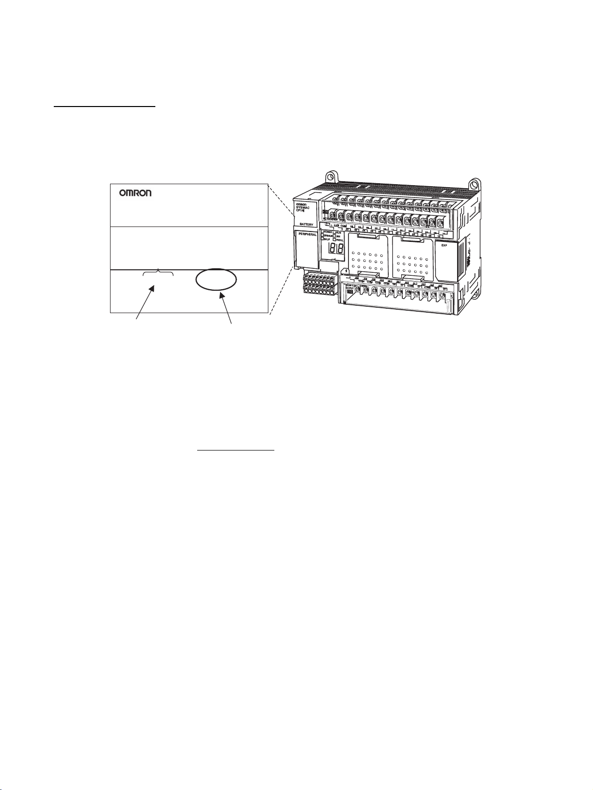
Unit Versions A “unit version” has been introduced to manage CPU Units in the CP Se ries
according to differences in functionality accompanying Unit upgrades.
Notation of Unit Versions
on Products
Product nameplate
CPU UNIT
Lot No. 28705 0000 Ver.1.0
OMRON Corporation MADE IN JAPAN
Lot No.
CP1H-XA40CDR-A
Confirming Unit Versions
with Support Software
The unit version is given to the right of the lot number on the nameplate of the
products for which unit versions are being managed, as shown below.
CP-series CPU Unit
Unit version (Example for Unit version 1.0)
CX-Programmer version 6.1 or highe r ca n be us ed t o c onfi rm the unit version
using one of the following two methods. (See note.)
• Using the PLC Information
• Using the Unit Manufacturing Information
Note CX-Programmer version 6.1 or lower cannot be used to conf irm un it versions
for CP-series CPU Units.
PLC Information
• If you know the device type and CP U type, select them in the Change
PLC Dialog Box, go online, and sel ect P LC - Edit - Information from the
menus.
• If you don't know the device type and CPU type but are connected directly
to the CPU Unit on a ser ial line, select PLC - Auto Online to go onlin e,
and then select PLC - Edit - Information from the menus.
In either case, the following PLC Information Dialog Box will be displayed.
vi
Page 6
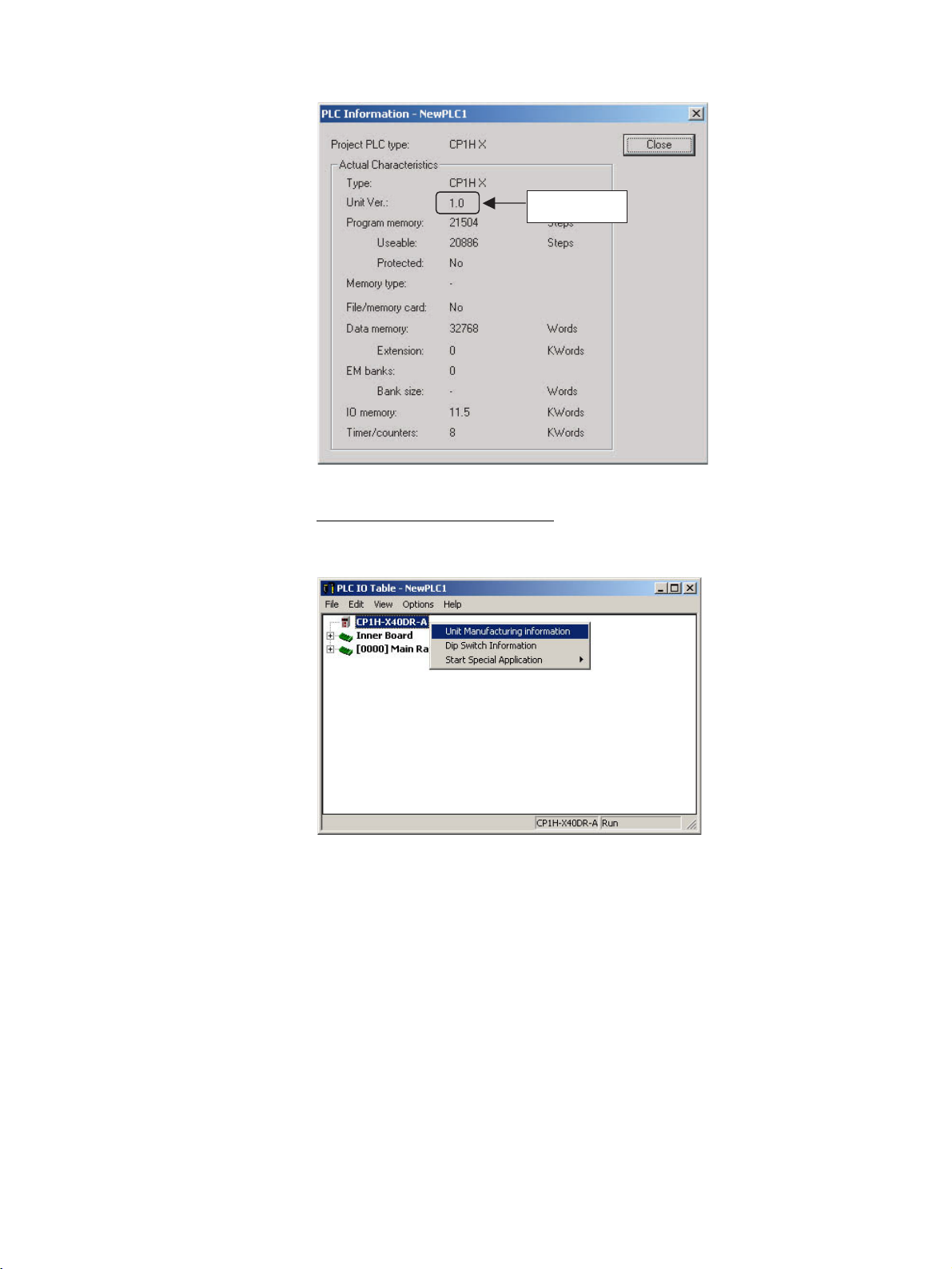
Unit version
Use the above display to confirm the unit version of the CPU Unit.
Unit Manufacturing Information
In the IO Table Window, right-click and sel ect Unit Manufacturing information - CPU Unit.
The following Unit Manufacturing information Dialog Box will be displayed.
vii
Page 7
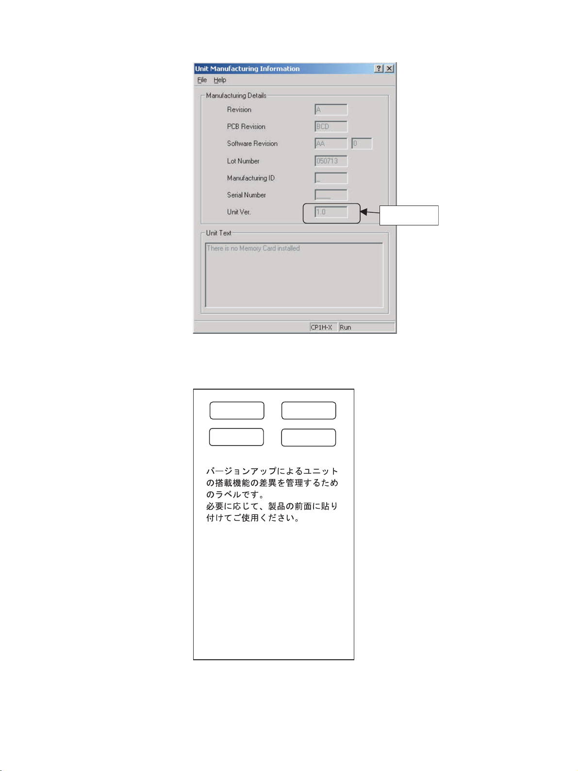
Unit version
Use the above display to confirm the uni t version of the CPU Unit connected
online.
Using the Unit Version
Labels
The following unit version labels are provided with the CPU Unit.
Ver.
Ver.
Ver.
1.0
Ver.
1.0
These Labels can be used
to manage differences
in the available
functions among the Units.
Place the appropriate label
on the front of the Unit to
show what Unit
version is actually being
used.
viii
These labels can be attached to the fron t of previous CPU Units to d ifferentiate between CPU Units of different unit versions.
Page 8

TABLE OF CONTENTS
PRECAUTIONS . . . . . . . . . . . . . . . . . . . . . . . . . . . . . . . . . . . xxi
1 Intended Audience. . . . . . . . . . . . . . . . . . . . . . . . . . . . . . . . . . . . . . . . . . . . . . . . . . . . . . . . . xxii
2 General Precautions. . . . . . . . . . . . . . . . . . . . . . . . . . . . . . . . . . . . . . . . . . . . . . . . . . . . . . . . xxii
3 Safety Precautions . . . . . . . . . . . . . . . . . . . . . . . . . . . . . . . . . . . . . . . . . . . . . . . . . . . . . . . . . xxii
4 Operating Environment Precautions . . . . . . . . . . . . . . . . . . . . . . . . . . . . . . . . . . . . . . . . . . . xxiv
5 Application Precautions. . . . . . . . . . . . . . . . . . . . . . . . . . . . . . . . . . . . . . . . . . . . . . . . . . . . .xxv
6 Conformance to EC Directives . . . . . . . . . . . . . . . . . . . . . . . . . . . . . . . . . . . . . . . . . . . . . . . xxviii
SECTION 1
Features and System Configuration . . . . . . . . . . . . . . . . . . . 1
1-1 Features and Main Functions. . . . . . . . . . . . . . . . . . . . . . . . . . . . . . . . . . . . . . . . . . . . . . . . . 2
1-2 System Configuration . . . . . . . . . . . . . . . . . . . . . . . . . . . . . . . . . . . . . . . . . . . . . . . . . . . . . . 15
1-3 Connecting Programming Devices . . . . . . . . . . . . . . . . . . . . . . . . . . . . . . . . . . . . . . . . . . . . 24
1-4 Function Charts . . . . . . . . . . . . . . . . . . . . . . . . . . . . . . . . . . . . . . . . . . . . . . . . . . . . . . . . . . . 35
1-5 Function Blocks. . . . . . . . . . . . . . . . . . . . . . . . . . . . . . . . . . . . . . . . . . . . . . . . . . . . . . . . . . . 38
SECTION 2
Nomenclature and Specifications . . . . . . . . . . . . . . . . . . . . . 41
2-1 Part Names and Functions . . . . . . . . . . . . . . . . . . . . . . . . . . . . . . . . . . . . . . . . . . . . . . . . . . .42
2-2 Specifications. . . . . . . . . . . . . . . . . . . . . . . . . . . . . . . . . . . . . . . . . . . . . . . . . . . . . . . . . . . . . 48
2-3 CP1H CPU Unit Operation . . . . . . . . . . . . . . . . . . . . . . . . . . . . . . . . . . . . . . . . . . . . . . . . . . 73
2-4 CPU Unit Operation . . . . . . . . . . . . . . . . . . . . . . . . . . . . . . . . . . . . . . . . . . . . . . . . . . . . . . . 81
2-5 CPU Unit Operating Modes. . . . . . . . . . . . . . . . . . . . . . . . . . . . . . . . . . . . . . . . . . . . . . . . . . 86
2-6 Power OFF Operation . . . . . . . . . . . . . . . . . . . . . . . . . . . . . . . . . . . . . . . . . . . . . . . . . . . . . . 88
2-7 Computing the Cycle Time . . . . . . . . . . . . . . . . . . . . . . . . . . . . . . . . . . . . . . . . . . . . . . . . . . 90
SECTION 3
Installation and Wiring . . . . . . . . . . . . . . . . . . . . . . . . . . . . . 103
3-1 Fail-safe Circuits . . . . . . . . . . . . . . . . . . . . . . . . . . . . . . . . . . . . . . . . . . . . . . . . . . . . . . . . . . 104
3-2 Installation Precautions . . . . . . . . . . . . . . . . . . . . . . . . . . . . . . . . . . . . . . . . . . . . . . . . . . . . . 105
3-3 Mounting . . . . . . . . . . . . . . . . . . . . . . . . . . . . . . . . . . . . . . . . . . . . . . . . . . . . . . . . . . . . . . . . 107
3-4 Wiring CP1H CPU Units. . . . . . . . . . . . . . . . . . . . . . . . . . . . . . . . . . . . . . . . . . . . . . . . . . . . 116
3-5 Wiring Methods . . . . . . . . . . . . . . . . . . . . . . . . . . . . . . . . . . . . . . . . . . . . . . . . . . . . . . . . . . . 124
3-6 CPM1A Expansion I/O Uni t Wiring . . . . . . . . . . . . . . . . . . . . . . . . . . . . . . . . . . . . . . . . . . . 133
ix
Page 9

TABLE OF CONTENTS
SECTION 4
I/O Memory Allocation . . . . . . . . . . . . . . . . . . . . . . . . . . . . . 139
4-1 Overview of I/O Memory Area . . . . . . . . . . . . . . . . . . . . . . . . . . . . . . . . . . . . . . . . . . . . . . . 140
4-2 I/O Area and I/O Allocations. . . . . . . . . . . . . . . . . . . . . . . . . . . . . . . . . . . . . . . . . . . . . . . . .148
4-3 Built-in Analog I/O Area (XA CPU Units Only) . . . . . . . . . . . . . . . . . . . . . . . . . . . . . . . . . 153
4-4 Data Link Area . . . . . . . . . . . . . . . . . . . . . . . . . . . . . . . . . . . . . . . . . . . . . . . . . . . . . . . . . . . 154
4-5 CPU Bus Unit Area. . . . . . . . . . . . . . . . . . . . . . . . . . . . . . . . . . . . . . . . . . . . . . . . . . . . . . . . 155
4-6 Special I/O Unit Area . . . . . . . . . . . . . . . . . . . . . . . . . . . . . . . . . . . . . . . . . . . . . . . . . . . . . . 156
4-7 Serial PLC Link Area . . . . . . . . . . . . . . . . . . . . . . . . . . . . . . . . . . . . . . . . . . . . . . . . . . . . . . 157
4-8 DeviceNet Area . . . . . . . . . . . . . . . . . . . . . . . . . . . . . . . . . . . . . . . . . . . . . . . . . . . . . . . . . . . 158
4-9 Internal I/O Area . . . . . . . . . . . . . . . . . . . . . . . . . . . . . . . . . . . . . . . . . . . . . . . . . . . . . . . . . . 159
4-10 Holding Area (H). . . . . . . . . . . . . . . . . . . . . . . . . . . . . . . . . . . . . . . . . . . . . . . . . . . . . . . . . . 159
4-11 Auxiliary Area (A). . . . . . . . . . . . . . . . . . . . . . . . . . . . . . . . . . . . . . . . . . . . . . . . . . . . . . . . . 160
4-12 TR (Temporary Relay) Area . . . . . . . . . . . . . . . . . . . . . . . . . . . . . . . . . . . . . . . . . . . . . . . . . 161
4-13 Timers and Counters . . . . . . . . . . . . . . . . . . . . . . . . . . . . . . . . . . . . . . . . . . . . . . . . . . . . . . . 162
4-14 Data Memory Area (D) . . . . . . . . . . . . . . . . . . . . . . . . . . . . . . . . . . . . . . . . . . . . . . . . . . . . . 164
4-15 Index Registers . . . . . . . . . . . . . . . . . . . . . . . . . . . . . . . . . . . . . . . . . . . . . . . . . . . . . . . . . . . 166
4-16 Data Registers . . . . . . . . . . . . . . . . . . . . . . . . . . . . . . . . . . . . . . . . . . . . . . . . . . . . . . . . . . . . 173
4-17 Task Flags . . . . . . . . . . . . . . . . . . . . . . . . . . . . . . . . . . . . . . . . . . . . . . . . . . . . . . . . . . . . . . . 175
4-18 Condition Flags . . . . . . . . . . . . . . . . . . . . . . . . . . . . . . . . . . . . . . . . . . . . . . . . . . . . . . . . . . . 175
4-19 Clock Pulses . . . . . . . . . . . . . . . . . . . . . . . . . . . . . . . . . . . . . . . . . . . . . . . . . . . . . . . . . . . . . 177
SECTION 5
Basic CP1H Functions . . . . . . . . . . . . . . . . . . . . . . . . . . . . . . 179
5-1 Interrupt Functions . . . . . . . . . . . . . . . . . . . . . . . . . . . . . . . . . . . . . . . . . . . . . . . . . . . . . . . . . 180
5-2 High-speed Counters. . . . . . . . . . . . . . . . . . . . . . . . . . . . . . . . . . . . . . . . . . . . . . . . . . . . . . . 204
5-3 Pulse Outputs. . . . . . . . . . . . . . . . . . . . . . . . . . . . . . . . . . . . . . . . . . . . . . . . . . . . . . . . . . . . . 224
5-4 Quick-response Inputs . . . . . . . . . . . . . . . . . . . . . . . . . . . . . . . . . . . . . . . . . . . . . . . . . . . . . . 315
5-5 Analog I/O (XA CPU Units). . . . . . . . . . . . . . . . . . . . . . . . . . . . . . . . . . . . . . . . . . . . . . . . . 318
SECTION 6
Advanced Functions . . . . . . . . . . . . . . . . . . . . . . . . . . . . . . . . 331
6-1 Serial Communications . . . . . . . . . . . . . . . . . . . . . . . . . . . . . . . . . . . . . . . . . . . . . . . . . . . . . 332
6-2 Analog Adjuster and External Analog Setting Input. . . . . . . . . . . . . . . . . . . . . . . . . . . . . . . 353
6-3 7-Segment LED Dis play . . . . . . . . . . . . . . . . . . . . . . . . . . . . . . . . . . . . . . . . . . . . . . . . . . . .355
6-4 Battery-free Operation. . . . . . . . . . . . . . . . . . . . . . . . . . . . . . . . . . . . . . . . . . . . . . . . . . . . . . 357
6-5 Memory Cassette Functions . . . . . . . . . . . . . . . . . . . . . . . . . . . . . . . . . . . . . . . . . . . . . . . . . 359
6-6 Program Protection . . . . . . . . . . . . . . . . . . . . . . . . . . . . . . . . . . . . . . . . . . . . . . . . . . . . . . . . 367
6-7 Failure Diagnosis Functions . . . . . . . . . . . . . . . . . . . . . . . . . . . . . . . . . . . . . . . . . . . . . . . . .374
6-8 Clock . . . . . . . . . . . . . . . . . . . . . . . . . . . . . . . . . . . . . . . . . . . . . . . . . . . . . . . . . . . . . . . . . . . 378
x
Page 10

TABLE OF CONTENTS
SECTION 7
Using CPM1A Expansion Units and Expansion I/O Units. 381
7-1 Connecting CPM1A Expansion Units and Expansion I/O Units . . . . . . . . . . . . . . . . . . . . . 382
7-2 Analog Input Units . . . . . . . . . . . . . . . . . . . . . . . . . . . . . . . . . . . . . . . . . . . . . . . . . . . . . . . . 383
7-3 Analog Output Units . . . . . . . . . . . . . . . . . . . . . . . . . . . . . . . . . . . . . . . . . . . . . . . . . . . . . . . 392
7-4 Analog I/O Units . . . . . . . . . . . . . . . . . . . . . . . . . . . . . . . . . . . . . . . . . . . . . . . . . . . . . . . . . . 400
7-5 Temperature Sensor Units . . . . . . . . . . . . . . . . . . . . . . . . . . . . . . . . . . . . . . . . . . . . . . . . . . .423
7-6 CompoBus/S I/O Link Units . . . . . . . . . . . . . . . . . . . . . . . . . . . . . . . . . . . . . . . . . . . . . . . . . 438
7-7 DeviceNet I/O Link Units . . . . . . . . . . . . . . . . . . . . . . . . . . . . . . . . . . . . . . . . . . . . . . . . . . .444
SECTION 8
Program Transfer, Trial Operation, and Debugging . . . . . 451
8-1 Program Transfer. . . . . . . . . . . . . . . . . . . . . . . . . . . . . . . . . . . . . . . . . . . . . . . . . . . . . . . . . . 452
8-2 Trial Operation and Debugging. . . . . . . . . . . . . . . . . . . . . . . . . . . . . . . . . . . . . . . . . . . . . . . 452
SECTION 9
Troubleshooting . . . . . . . . . . . . . . . . . . . . . . . . . . . . . . . . . . . 459
9-1 Error Classification and Confirmation. . . . . . . . . . . . . . . . . . . . . . . . . . . . . . . . . . . . . . . . . . 460
9-2 Troubleshooting. . . . . . . . . . . . . . . . . . . . . . . . . . . . . . . . . . . . . . . . . . . . . . . . . . . . . . . . . . . 465
9-3 Error Log. . . . . . . . . . . . . . . . . . . . . . . . . . . . . . . . . . . . . . . . . . . . . . . . . . . . . . . . . . . . . . . . 477
9-4 Troubleshooting Unit Errors . . . . . . . . . . . . . . . . . . . . . . . . . . . . . . . . . . . . . . . . . . . . . . . . .478
SECTION 10
Inspection and Maintenance . . . . . . . . . . . . . . . . . . . . . . . . . 481
10-1 Inspections. . . . . . . . . . . . . . . . . . . . . . . . . . . . . . . . . . . . . . . . . . . . . . . . . . . . . . . . . . . . . . . 482
10-2 Replacing User-serviceable Parts . . . . . . . . . . . . . . . . . . . . . . . . . . . . . . . . . . . . . . . . . . . . . 484
Appendices
A Standard Models . . . . . . . . . . . . . . . . . . . . . . . . . . . . . . . . . . . . . . . . . . . . . . . . . . . . . . . . . . 489
B Dimensions Diagrams . . . . . . . . . . . . . . . . . . . . . . . . . . . . . . . . . . . . . . . . . . . . . . . . . . . . . .497
C Auxiliary Area Allocations by Function . . . . . . . . . . . . . . . . . . . . . . . . . . . . . . . . . . . . . . . . 505
D Auxiliary Area Allocations by Address . . . . . . . . . . . . . . . . . . . . . . . . . . . . . . . . . . . . . . . . 525
E Memory Map . . . . . . . . . . . . . . . . . . . . . . . . . . . . . . . . . . . . . . . . . . . . . . . . . . . . . . . . . . . . 571
F Connections to Serial Communications Option Boards . . . . . . . . . . . . . . . . . . . . . . . . . . . . 573
G PLC Setup . . . . . . . . . . . . . . . . . . . . . . . . . . . . . . . . . . . . . . . . . . . . . . . . . . . . . . . . . . . . . . . 599
Index. . . . . . . . . . . . . . . . . . . . . . . . . . . . . . . . . . . . . . . . . . . . . 629
Revision History . . . . . . . . . . . . . . . . . . . . . . . . . . . . . . . . . . . 635
xi
Page 11

TABLE OF CONTENTS
xii
Page 12

About this Manual:
This manual descr ibes installation and operat ion of the CP-series Program mable Controllers (PLCs)
and includes the sections described below. The CP Series p rovid es advanced package-type PLCs
based on OMRON’s advanced control technologies and vast experience in automated control.
Please read this manual carefully and be sure you understand the information provided before
attempting to install or opera te a CP-series P LC. Be sure to read the precautions provided in the following section.
Definition of the CP Series
The CP Series is centered around the CP1H CPU Units and is designed with the same basic architecture as the CS and CJ Series. The Special I/O Uni ts and CPU Bus Unit s of the CJ Ser ies ca n thus be
used. CJ-series Basic I/O Units, however, cannot be used. Always use CPM1A Expansion Un its and
CPM1A Expansion I/O Units when expanding I/O capacity.
I/O words are allocated in the same way as the CPM1A/CPM2A PLCs, i.e., using fixed areas for inputs
and outputs.
CS Series
CS1-H CPU Units
CS1H-CPU@@H
CS1G-CPU@@H
CS1 CPU Units
CS1H-CPU@@ (-V1)
CS1G-CPU@@ (-V1)
CS1D CPU Units
CS1D CPU Units for
Duplex-CPU System
CS1D-CPU
CS1D CPU Units for
Single-CPU System
CS1D-CPU S
CS1D Process CPU Units
CS1D-CPU
CS-series Basic I/O Units
CS-series Special I/O Units
CS-series CPU Bus Units
CS-series Power Supply Units
Note: Products specifically for the CS1D
Series are required to use CS1D
CPU Units.
CS/CJ/CP Series
CJ Series
CJ1-H CPU Units
CJ1H-CPU@@H
CJ1G-CPU@@H
CJ1G -CPU@@P
(Loop CPU Unit)
CJ1M CPU Unit
CJ1M-CPU@@
@@H
@@
@@P
CJ1 CPU Unit
CJ1G-CPU@@
CJ-series Basic I/O Units
CJ-series Special I/O Units
CJ-series CPU Bus Units
CJ-series Power Supply Units
CPM1A Expansion I/O Units
CPM1A Expansion Units
CJ-series Special I/O Units
CJ-series CPU Bus Units
CP Series
CP1H CPU Units
CP1H-X@@@@-@
CP1H-XA@@@@-@
CP1H-Y@@@@-@
xiii
Page 13

Precautions provides general precautions for using the Programmable Controller and related devices.
Section 1 introduces the features of the CP1 H and describes its config uration. It also describes th e
Units that are available and connection methods for Programming Devices and other peripheral
devices.
Section 2 describes the names and functions of CP1H parts and provides CP1H specifications.
Section 3 describes how to install and wire the CP1H.
Section 4 describes the structure and functions of the I/O Memory Areas and Parameter Areas.
Section 5 describes the CP1H’s interrupt and high-speed counter functions.
Section 6 describes all of the advanced functions of the CP1H that can be used to achieve specific
application needs.
Section 7 describes how to use CPM1A Expansion Units and Expansion I/O Units
Section 8 describes the processes used to transfer the program to the CPU Unit and the functions that
can be used to test and debug the program.
Section 9 provides information on hardware and software errors that occur during CP1H operation
Section 10 provides inspection and maintenance information.
The Appendices provide product lists, dimensions, tables of Auxiliary Area allocations, and a memory
map.
xiv
Page 14

Related Manuals
The following manuals are used for the CP-series CPU Units. Refer to these manuals as required.
Cat. No. Model numbers Manual name Description
W450 CP1H-X40D@-@
CP1H-XA40D@-@
CP1H-Y20DT-D
W451 CP1H-X40D@-@
CP1H-XA40D@-@
CP1H-Y20DT-D
W342 CS1G/H-CPU@@H
CS1G/H-CPU@@-V1
CS1D-CPU@@H
CS1D-CPU@@S
CS1W-SCU21
CS1W-SCB21-V1/41-V1
CJ1G/H-CPU@@H
CJ1G-CPU@@P
CP1H-CPU@@
CJ1G-CPU@@
CJ1W-SCU21-V1/41-V1
W446 WS02-CXPC1-E-V70 SYSMAC CX-Pro-
W447 WS02-CXPC1-E-V70 SYSMAC CX-Pro-
W444 CXONE-AL@@C-E CX-One FA Inte-
W445 CXONE-AL@@C-E CX-Int egrator Opera-
W344 WS02-PSTC1-E CX-Protocol Opera-
SYSMAC CP Series
CP1H CPU Unit
Operation Manual
SYSMAC CP Series
CP1H CPU Unit Programming Manual
SYSMAC CS/CJseries Communica tions Commands Reference Manual
grammer
Ver. 7.0 Operation
Manual
grammer Ver. 7.0
Operation Manual
Function Blocks
grated Tool Package
Setup Manual
tion Manual
tion Manual
Provides the f o llo wing in f o rmation on th e CP Se ries:
•Overview, design, installation, maintenance, and
other basic specifications
•Features
• System confi guration
•Mounting and wiring
•I/O memory allocation
• Troubleshooting
Use this manual together with the CP1H Program-
mable Controllers Programming Manual (W451).
Provides the f o llo wing in f o rmation on th e CP Se ries:
•Programming instructions
• Programming methods
•Tasks
• File memory
•Functions
Use this manual together with the CP1H Program-
mable Controllers Operation Manual (W450).
Describes commands addressed to CS-series and
CJ-series CPU Units , incl uding C-mod e comm ands
and FINS commands.
Note This manual describes on commands
address to CPU Units regardless of the communications path. (CPU Unit serial por ts,
Serial Communications Unit/Board ports, and
Communications Unit ports can be used.)
Refer to the relevant operation manuals for
information on commands addresses to Special I/O Units and CPU Bus Units.
Provides inf ormation on instal ling a nd oper at ing the
CX-Programmer f o r al l fun ct ion s except for function
blocks.
Provides specifications and oper ating proc edures
for function blocks. Function blocks can be used
with CX-Programmer Ver. 6.1 or highe r and either a
CS1-H/CJ1-H CPU Unit with a uni t v ersi on of 3.0 or
a CP1H CPU Unit. Refer to W446 for operating procedures for functions other than function blocks.
Provides an overview of the CX-One FA Integrated
Tool and installation procedures.
Describes CX-Integrator operating procedures and
provides inf ormatio n on ne tw ork config ur ation (data
links, routing tables, Communications Units setup,
etc.
Provides operat ing proc edures f or crea ting pro tocol
macros (i.e., communications sequences) with the
CX-Protocol and other information on protocol macros.
The CX-Protocol is required to create prot oc ol ma cros for user-specific serial communications or to
customize the standard system protocols.
xv
Page 15

xvi
Page 16

Read and Understand this Manual
Please read and understand this manual before using the product. Please consult your OMRON
representative if you have any questions or comments.
Warranty and Limitations of Liability
WARRANTY
OMRON's exclusive warranty is that the products are free from defects in materials and workmanship for a
period of one year (or other period if specified) from date of sale by OMRON.
OMRON MAKES NO WARRANTY OR REPRESENTATION, EXPRESS OR IMPLIED, REGARDING NONINFRINGEMENT, MERCHANTABILITY, OR FITNESS FOR PARTICULAR PURPOSE OF THE
PRODUCTS. ANY BUYER OR USER ACKNOWLEDGES THAT THE BUYER OR USER ALONE HAS
DETERMINED THAT THE PRODUCTS WILL SUITABLY MEET THE REQUIREMENTS OF THEIR
INTENDED USE. OMRON DISCLAIMS ALL OTHER WARRANTIES, EXPRESS OR IMPLIED.
LIMITATIONS OF LIABILITY
OMRON SHALL NOT BE RESPONSIBLE FOR SPECIAL, INDIRECT, OR CONSEQUENTIAL DAMAGES,
LOSS OF PROFITS OR COMMERCIAL LOSS IN ANY WAY CONNECTED WITH THE PRODUCTS,
WHETHER SUCH CLAIM IS BASED ON CONTRACT, WARRANTY, NEGLIGENCE, OR STRICT
LIABILITY.
In no event shall the responsibility of OMRON for any act exceed the individual price of the product on which
liability is asserted.
IN NO EVENT SHALL OMRON BE RESPONSIBLE FOR WARRANTY, REPAIR, OR OTHER CLAIMS
REGARDING THE PRODUCTS UNLESS OMRON'S ANALYSIS CONFIRMS THAT THE PRODUCTS
WERE PROPERLY HANDLED, STORED, INSTALLED, AND MAINTAINED AND NOT SUBJECT TO
CONTAMINATION, ABUSE, MISUSE, OR INAPPROPRIATE MODIFICATION OR REPAIR.
xvii
Page 17

Application Considerations
SUITABILITY FOR USE
OMRON shall not be responsible for conformity with any standards, codes, or regulations that apply to the
combination of products in the customer's application or use of the products.
At the customer's request, OMRON will provide applicable third party certification documents identifying
ratings and limitations of use that apply to the products. This information by itself is not sufficient for a
complete determination of the suitability of the products in combination with the end product, machine,
system, or other application or use.
The following are some examples of applications for which particular attention must be given. This is not
intended to be an exhaustive list of all possible uses of the products, nor is it intended to imply that the uses
listed may be suitable for the products:
• Outdoor use, uses involving potential chemical contamination or electrical interference, or conditions or
uses not described in this manual.
• Nuclear energy control systems, combustion systems, railroad systems, aviation systems, medical
equipment, amusement machines, vehicles, safety equipment, and installations subject to separate
industry or government regulations.
• Systems, machines, and equipment that could present a risk to life or property.
Please know and observe all prohibitions of use applicable to the products.
NEVER USE THE PRODUCTS FOR AN APPLICATION INVOLVING SERIOUS RISK TO LIFE OR
PROPERTY WITHOUT ENSURING THAT THE SYSTEM AS A WHOLE HAS BEEN DESIGNED TO
ADDRESS THE RISKS, AND THA T THE OMRON PR ODUCTS ARE PROPERLY RATED AND INSTALLED
FOR THE INTENDED USE WITHIN THE OVERALL EQUIPMENT OR SYSTEM.
PROGRAMMABLE PRODUCTS
OMRON shall not be responsible for the user's programming of a programmable product, or any
consequence thereof.
xviii
Page 18

Disclaimers
CHANGE IN SPECIFICATIONS
Product specifications and accessories may be changed at any time based on improvements and other
reasons.
It is our practice to change model numbers when published ratings or features are changed, or when
significant construction changes are made. However, some specifications of the products may be changed
without any notice. When in doubt, special model numbers may be assigned to fix or establish key
specifications for your application on your request. Please consult with your OMRON representative at any
time to confirm actual specifications of purchased products.
DIMENSIONS AND WEIGHTS
Dimensions and weights are nominal and are not to be used for manufacturing purposes, even when
tolerances are shown.
PERFORMANCE DATA
Performance data given in this manual is provided as a guide for the user in determining suitability and does
not constitute a warranty. It may represent the result of OMRON's test conditions, and the users must
correlate it to actual application requirements. Actual performance is subject to the OMRON Warranty and
Limitations of Liability.
ERRORS AND OMISSIONS
The information in this manual has been carefully checked and is believed to be accurate; however, no
responsibility is assumed for clerical, typographical, or proofreading errors, or omissions.
xix
Page 19

xx
Page 20

PRECAUTIONS
This section provides general precautions for using the CP-series Programmable Controllers (PLCs) and related devices.
The information contained in this section is important for the safe and reliable application of Programmable
Controllers. You must read this s ection and understand t he information contained before attempting to se t up or
operate a PLC system.
1 Intended Audience . . . . . . . . . . . . . . . . . . . . . . . . . . . . . . . . . . . . . . . . . . . . . xxii
2 General Precautions . . . . . . . . . . . . . . . . . . . . . . . . . . . . . . . . . . . . . . . . . . . . xxii
3 Safety Precautions. . . . . . . . . . . . . . . . . . . . . . . . . . . . . . . . . . . . . . . . . . . . . . xxii
4 Operating Environment Precautions . . . . . . . . . . . . . . . . . . . . . . . . . . . . . . . . xxiv
5 Application Precautions . . . . . . . . . . . . . . . . . . . . . . . . . . . . . . . . . . . . . . . . . xxv
6 Conformance to EC Directives . . . . . . . . . . . . . . . . . . . . . . . . . . . . . . . . . . . . xxviii
6-1 Applicable Directives . . . . . . . . . . . . . . . . . . . . . . . . . . . . . . . . . . . . xxviii
6-2 Concepts . . . . . . . . . . . . . . . . . . . . . . . . . . . . . . . . . . . . . . . . . . . . . . xxviii
6-3 Conformance to EC Directives. . . . . . . . . . . . . . . . . . . . . . . . . . . . . xxviii
6-4 Relay Output Noise Reduction Methods . . . . . . . . . . . . . . . . . . . . . xxix
6-5 Conditions for Meeting EMC Directives
when Using CPM1A Relay Expansion I/O Units. . . . . . . . . . . . . . . xxx
xxi
Page 21

Intended Audience 1
1 Intended Audience
This manual is intended for the following personnel, who must also have
knowledge of electrical systems (an electrical engineer or the equivalent).
• Personnel in charge of installing FA systems.
• Personnel in charge of designing FA systems.
• Personnel in charge of managing FA systems and facilities.
2 General Precautions
The user must operate t he product according to t he performance specifications described in the operation manuals.
Before using the product under conditions which are not described in the
manual or applying the produ ct to nuclear control s ystems, railroad systems,
aviation systems, vehicles, combustion systems, me dical equipmen t, amusement machines, safety equipment, and oth er systems, machines, and equi pment that may have a serious influence on lives and property if used
improperly, consult your OMRON representative.
Make sure that the ratings and performan ce charact er is ti cs of the pr od uc t are
sufficient for the systems, machi nes, and equipment, and be sure to provide
the systems, machines, and equipment with double safety mechanisms.
This manual provides informat ion for programming and operat ing the Un it. B e
sure to read this manual before attempting to use the Unit and keep this manual close at hand for reference during operation.
!WARNING It is extremely impor tant that a PLC and al l PLC Units b e used for the spec i-
fied purpose and under the specified conditions, especially in applications that
can directly or indirectly affect human life. You must consult with your OMRON
representative before applying a PLC System to th e above-mentioned applications.
3 Safety Precautions
!WARNING Do not attempt to take any Unit apart while the power is being supplied. Doing
so may result in electric shock.
!WARNING Do not touch any of the te r minals o r ter minal blocks while the power is bein g
supplied. Doing so may result in electric shock.
!WARNING Do not attempt to disassemble, repair, or modify any Units. Any attempt to do
so may result in malfunction, fire, or electric shock.
!WARNING Provide safety measures in external circuits (i.e., not in the Programmable
Controller), includin g the following items, to ensure safety in the system if an
abnormality occurs due to malfunc tion of the PLC or anoth er external factor
affecting the PLC operation. Not doing so may result in serious accidents.
xxii
• Emergency stop cir cuits, inter lock circui ts, limit cir cuits, and sim ilar safety
measures must be provided in external control circuits.
Page 22

Safety Precautions 3
• The PLC will turn OFF all outputs when its self-diagnosis function detects
any error or when a severe failure alarm (FALS) instruction is executed.
As a counterme asure for such errors, external safety measures must be
provided to ensure safety in the system.
• The PLC or outputs may remain ON or OFF due to deposits on or burning
of the output relays, or destruc tio n of th e ou tpu t transis to rs. As a c ou ntermeasure for such problems, extern al safety measures must be provide d
to ensure safety in the system.
• When the 24-V DC output (service power supply to the PLC) is overloaded or shor t-circuited, the voltage may drop and result in the out puts
being turned OFF. As a countermeasure for such problems, external
safety measures must be provided to ensure safety in the system.
!WARNING Fail-safe measures must be taken by the customer to ensure safety in the
event of incorrect, missing, or abnormal signals caused by broken signal lines,
momentary power in terruptions, or other causes. Not doing so may result in
serious accidents.
!Caution Execute online edit only after confirming that no adverse effects will be
caused by extending the cycle time. Other wise, the input signals may not be
readable.
!Caution Confirm safety at the destination node before transferring a program to
another node or editing the I/O area. Doing either of thes e withou t confir m ing
safety may result in injury.
!Caution Tighten the screws on the terminal block of the AC power supply to the torque
specified in this manual. The loose s crews may result in burning o r malfunction.
!Caution Do not touch anywhere near the power supply parts or I/O terminals while the
power is ON, and immediately after tur ning OFF the power. The hot surface
may cause burn injury.
!Caution Pa y careful attention to the polarities (+/-) when wiring the DC power supply . A
wrong connection may cause malfunction of the system.
!Caution When connecting the PLC to a computer or other peripheral device, either
ground the 0 V side of the external power supply or do not ground the external
power supply at all. Otherwise the external power supply may be shorted
depending on the connection methods of the peripheral device. DO NOT
ground the 24 V sid e of the exter nal power suppl y, as shown in t he following
diagram.
Non-insulated DC power supply
24 V
Twisted-pair
cable
FG
0 V
0 V
CPU Unit
FG
FG
0 V
Peripheral device
FG
xxiii
Page 23

Operating Environment Precautions 4
!Caution After programming (or repr ogrammi ng) using the IOWR instruction, confir m
that correct operation is possible with the new ladder program and data before
starting actual operation. Any irregularities may cause the product to stop
operating, resulting in unexpected operation in machinery or equipment.
!Caution The CP1H CPU Units automatically back up the user program and parameter
data to flash memor y when these are written to the CPU Unit. I/O memory
(including the DM Area , counter present values and Completion Flags, an d
HR Area), however, is not written to flash memory. The DM Area, counter
present values and Completion Flags, and HR Area can be held during power
interruptions with a ba ttery. If there is a batter y error, the contents of these
areas may not be accurate af ter a power interruption. If the con tents of the
DM Area, counter present values and Completion Flags, and HR Area are
used to control external outputs, prevent inappropriate outputs from being
made whenever the Battery Error Flag (A402.04) is ON.
4 Operating Environment Precautions
!Caution Do not operate the control system in the following locations:
• Locations subject to direct sunlight.
• Locations subject to temperatures or humidity outside the range specified
in the specifications.
• Locations subject to condensation as the result of severe changes in temperature.
• Locations subject to corrosive or flammable gases.
• Locations subject to dust (especially iron dust) or salts.
• Locations subject to exposure to water, oil, or chemicals.
• Locations subject to shock or vibration.
!Caution Take appropriate and su fficient counterm easures when installing sys tems in
the following locations:
• Locations subject to static electricity or other forms of noise.
• Locations subject to strong electromagnetic fields.
• Locations subject to possible exposure to radioactivity.
• Locations close to power supplies.
!Caution The operating environment of th e PLC S ystem c an have a large effect on th e
longevity and reliability of the sy stem. Improper operating environme nts can
lead to malfunction, failure, and other unforeseeable problems with the PLC
System. Make sure that the operating environment is within the specified conditions at installati on and remains within the specifi ed conditions during the
life of the system.
xxiv
Page 24

Application Precautions 5
5 Application Precautions
Observe the following precautions when using the PLC System.
!WARNING Always heed these precautions. Failure to abide by the following precautions
could lead to serious or possibly fatal injury.
• Always connect to 100
to a ground of 100
• Always turn OFF the power su pply to the PLC before attempting a ny of
the following. Not turning OFF the power supply may result in malfunction
or electric shock.
• Mounting or dismounting Expansion Units or any other Units
• Connecting or removing the Memory Cassette or Option Board
• Setting DIP switches or rotary switches
• Connecting or wiring the cables
• Connecting or disconnecting the connectors
!Caution Failure to abide by the following precautions could lead to faulty operation of
the PLC or the system, or co uld dam age the PLC or PLC Uni ts. Always heed
these precautions.
• Install external breakers and take other safety measures against short-circuiting in external wiring. Insufficient safety measures agai nst short-circuiting may result in burning.
• Mount the Unit only after checking the connectors and terminal blocks
completely.
• Be sure that all the terminal screws and cable connector screws are tightened to the torque s pecified in the relevant manuals. Incorrect tig htening
torque may result in malfunction.
• Wire all connections correctly according to instructions in this manual.
• Always use the power supply voltage specified in the operati on manuals.
An incorrect voltage may result in malfunction or burning.
• Take appropriate m easures to ensure that the specified power with the
rated voltage and frequency is supplied. Be partic ularly car eful in places
where the power supply is unstable. An incorrect power supply may result
in malfunction.
• Leave the label attached to the Unit when wiring. Removing the label may
result in malfunction.
• Remove the label after the completion of wiring to ensure proper heat dissipation. Leaving the label attached may result in malfunction.
• Use crimp terminals for wiring. Do not connect bare stranded wires
directly to terminals. Connection of bare stranded wires may result in
burning.
• Do not apply voltages to the in put terminals in excess of the rated input
voltage. Excess voltages may result in burning.
• Do not apply voltages o r connect loads to the output ter minals in excess
of the maximum switching capac i ty. Excess voltage or loads may result in
burning.
Ω or less when installing the Units. Not connecting
Ω or less may result in electric shock.
xxv
Page 25

Application Precautions 5
• Be sure that the ter minal blocks, connectors, Option Boards, and other
items with locking devices are properly locked into place. Improper locking
may result in malfunction.
• Disconnect the functional ground terminal when performing withstand
voltage tests. Not disconnecting the functional ground terminal may result
in burning.
• Wire correctly and double-check all the wiring or the setting switches
before turning ON the power suppl y. Incorrect wir ing may result in burning.
• Check that the DIP switches and data memory (DM) are properly set
before starting operation .
• Check the user program for proper execution before actually running it o n
the Unit. Not checking the program may result in an unexpected operation.
• Resume operation only after transferring to the new CPU Unit and/or Special I/O Units the contents of the DM, HR, and CNT A reas required for
resuming operation. Not doing so may result in an unexpected operation.
• Confirm that no ad verse effect will occur in the system before attemptin g
any of the following. Not doing so may result in an unexpected operation.
• Changing the operating mode of the PLC ( includi ng the se tting of th e
startup operating mode).
• Force-setting/force-resetting any bit in memory.
• Changing the present value of any word or any set value in memory.
• Do not pull on the cables or bend the cables beyond their natural limit.
Doing either of these may break the cables.
• Do not place objects on top of the cables. Doing so may break the cables.
• When replacing p arts, be sure to confi rm that the rating of a new par t is
correct. Not doing so may result in malfunction or burning.
• Before touching the Unit, be su re to firs t to uc h a grounde d m etal li c obj ec t
in order to discharge a ny static buildup. Not doing so may result in malfunction or damage.
• Do not touch the Expansion I/ O Unit Conn ec tin g Cable while the power is
being supplied in order to prevent malfunction due to static electricity.
• Do not turn O FF the power supply to the Uni t while data is being tran sferred.
• When transporting or storing the product, cover the PCBs with electrically
conductive materials to prevent LSIs and ICs from being damaged by
static electricity, and also keep the product within the specified storage
temperature range.
• Do not touch the mounted par ts or the rear surface of PCBs because
PCBs have sharp edges such as electrical leads.
• Double-check the pin numbers when assembling an d wiring t he connectors.
• Wire correctly according to specified procedures.
• Do not connect pin 6 (+5V) on the RS-232C Opti on Board on the CPU
Unit to any external device other than the NT-AL001 or CJ1W-CIF11 Conversion Adapter. The external device and the CPU Unit may be damaged.
• Use the dedicated conne cting cables specified in this manual to connect
the Units. Using commerc ially avai lable RS-232C computer cables may
cause failures in external devices or the CPU Unit.
xxvi
Page 26

Application Precautions 5
• Check that data link tables an d parameters are p roperly set before star ting operation. Not doing so may result in un expe cted operation. Even if
the tables and parameters are properly set, confirm that no adverse
effects will occur in the system before running or stopping data links.
• Transfer a routing table to the CPU Unit only after confirming that no
adverse effects will be caused by restarting CPU Bus Units, which is automatically done to make the new tables effective.
• The user program and param eter a r ea data i n th e C PU Uni t i s backed up
in the built-in flash memory. The BKUP indicator will light on the fr ont of
the CPU Unit when the backup operation i s in progress. Do not tur n OFF
the power supply to the CPU Unit when the BKUP indicator is lit. The data
will not be backed up if power is turned OFF.
• Do not turn OFF the power supply to the PLC while the Memory Cassette
is being accessed. Doin g so may cor rupt the data in the Memory Cassette. The 7-segment LED will light to indicate writing progress while the
Memory Cassette is being accessed. Wait for the LED display to go out
before turning OFF the power supply to the PLC.
• Before replacing the batter y, supply power to the CPU Unit for at least 5
minutes and then complete battery repla cement within 5 minutes of tu rn
OFF the power supply. Memory data may be corrupted if this precaution is
not observed.
• Always use the following size wire when connecting I/O Units, Spec ia l I/O
Units, and CPU Bus Units: AWG22 to AWG18 (0.32 to 0.82 mm
• UL standards required that batteries be replaced only by experienced
technicians. Do not allow unqualified pe rsons to replace batteries. Also,
always follow the replacement procedure provided in the manual.
• Never short-circuit the positive and negative terminals of a battery or
charge, disassemble, heat, or incinerate the battery. Do not s ubject the
battery to str ong shocks or defor m the barr y by apply ing pressu re. Doing
any of these may result in leakage, ruptur e, heat gene ration, or ig nit ion of
the battery. Dispose of any battery that has been dropped on the f loor or
otherwise subjected to excessive shock. Batteries that have been subjected to shock may leak if they are used.
• Always construct external circuits so that the power to the PLC it turne d
ON before the power to the control system is turned ON. If the PLC power
supply is turned ON afte r the c ontrol power su pply, temporary errors may
result in control system signals bec ause the outpu t ter minals on DC Output Units and other U nits will mo mentar ily tur n ON when power is tur ned
ON to the PLC.
• Fail-safe measures must be taken by the customer to ensure safety in the
event that outputs from Output Units remain ON as a result of internal circuit failures, which can occur in relays, transistors, and other elements.
• If the I/O Hold Bit is turned ON, the outputs from the PLC will not be
turned OFF and will maintain their previous status when the PLC is
switched from RUN or MONITOR mode to PROGRAM mode. Make sure
that the external loads will not produce dangerous conditi ons when this
occurs. (When operation stops for a fatal error, including those produced
with the FALS(007) instruction, all outputs from Outpu t Unit will be turned
OFF and only the internal output status will be maintained.)
2
).
xxvii
Page 27

Conformance to EC Directives 6
• Dispose of the product and batteries according to local ordinances as
they apply.
Have qualified specialists properl y dispose o f used batter ies as ind ustrial
waste.
6 Conformance to EC Directives
6-1 Applicable Directives
•EMC Directives
• Low Voltage Directive
6-2 Concepts
EMC Directives
OMRON devices that comply with EC Directives also conform to the r elated
EMC standards so tha t they can be more e as ily built in to ot her d evices or th e
overall machine. The actual products have been checked for conformity to
EMC standards (see the following note). Whether the products conform to the
standards in the system used by the custo mer, however, must be che cked by
the customer.
EMC-related perfor ma nce o f th e O M RON devices that c omp ly wi th EC Di re ctives will vary depending on the configuration, wi ring, and oth er conditions of
the equipment or control panel on which the OMRON devices are installed .
The customer must, therefore, perform the fina l check to conf ir m th at devices
and the overall machine conform to EMC standards.
Note The applicable EMC (Electromagnetic Compatibility) standard is EN61131-2.
Low Voltage Directive
Always ensure that devices operating at voltage s of 50 to 1,00 0 V AC and 75
to 1,500 V DC meet the required safety standards for the PLC (EN61131-2).
6-3 Conformance to EC Directives
The CP1H PLCs comply with E C Directives. To ensure that the machine or
device in which the CP1H PLC is us ed complies with EC Direc tives, the PLC
must be installed as follows:
1,2,3... 1. The CP1H PLC must be installed within a control panel.
2. You must use reinforced insulation or double insulation for the DC power
supplies used for I/O Units and CPU Units requiring DC power. The output
holding time must be 10 ms minimum for the DC power supply connected
to the power supply terminals on Units requiring DC power.
3. CP1H PLCs complying with EC Directive s also conform to EN61131-2.
Radiated emission characteristics (10-m regulations) may vary depending
on the configuration of the control panel used, other devices connected to
the control panel, wiring, and other conditions. You must therefore confirm
that the overall machine or equipment complies with EC Directives.
xxviii
Page 28
Conformance to EC Directives 6
6-4 Relay Output Noise Reduction Methods
The CP1H PLCs conforms to the Commo n Emissi on Stand ards (EN61131- 2)
of the EMC Directives. However, noise generated by relay output switching
may not satisfy these Standards. In such a ca se, a noise filter must be connected to the load side o r other appropriate counter measures must be provided external to the PLC.
Countermeasures taken to satisfy the standards vary depending on the
devices on the load side, wiring, co nfi guration of mac hi nes, etc . Following are
examples of countermeasures for reducing the generated noise.
Countermeasures
Countermeasur es are not required if the f requency of load switching for the
whole system with the PLC included is less than 5 times per minute.
Countermeasures are required if the frequency of load switching for the whole
system with the PLC included is more than 5 times per minute.
Note Refer to EN61131-2 for more details.
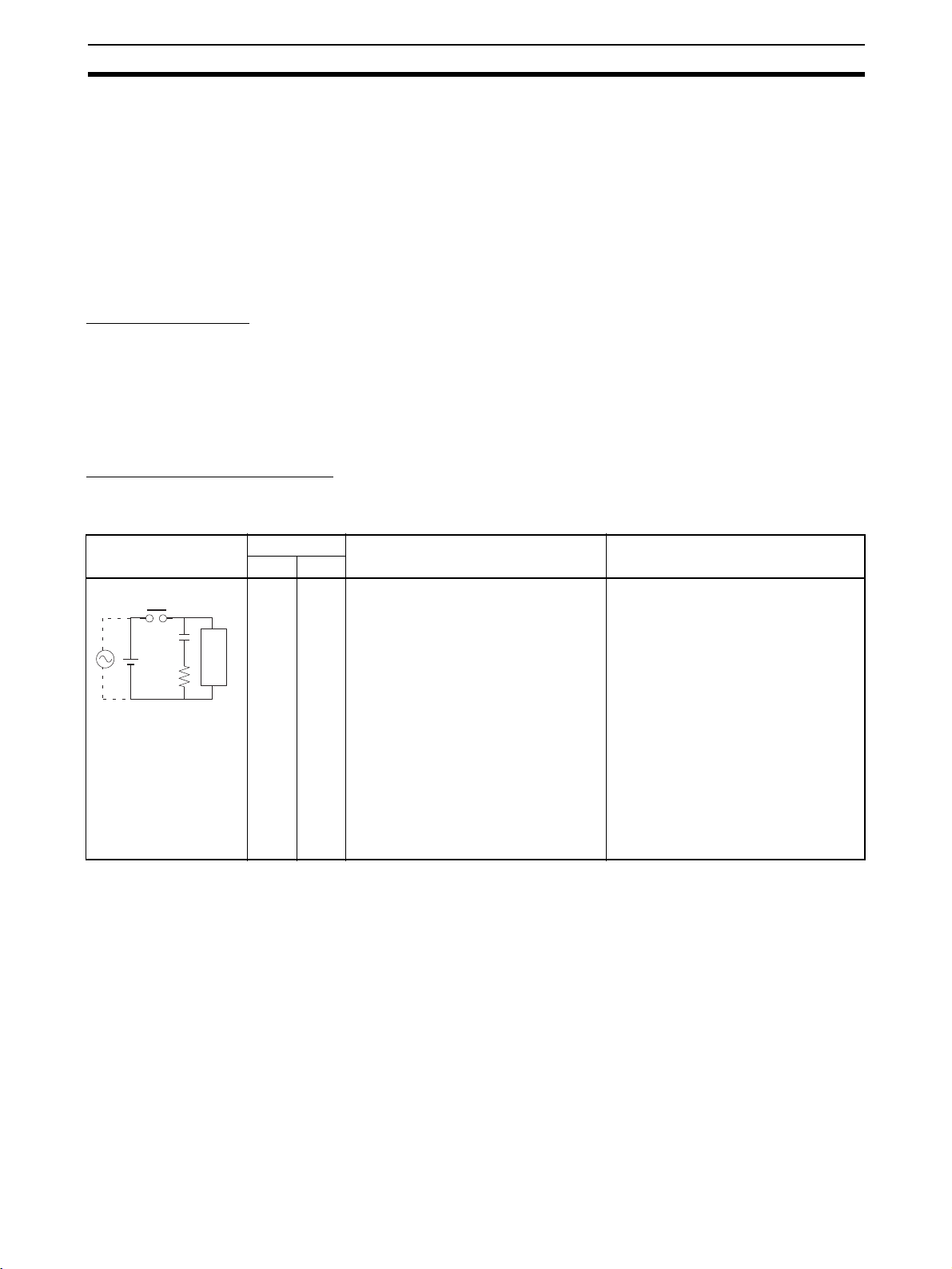
Countermeasure Examples
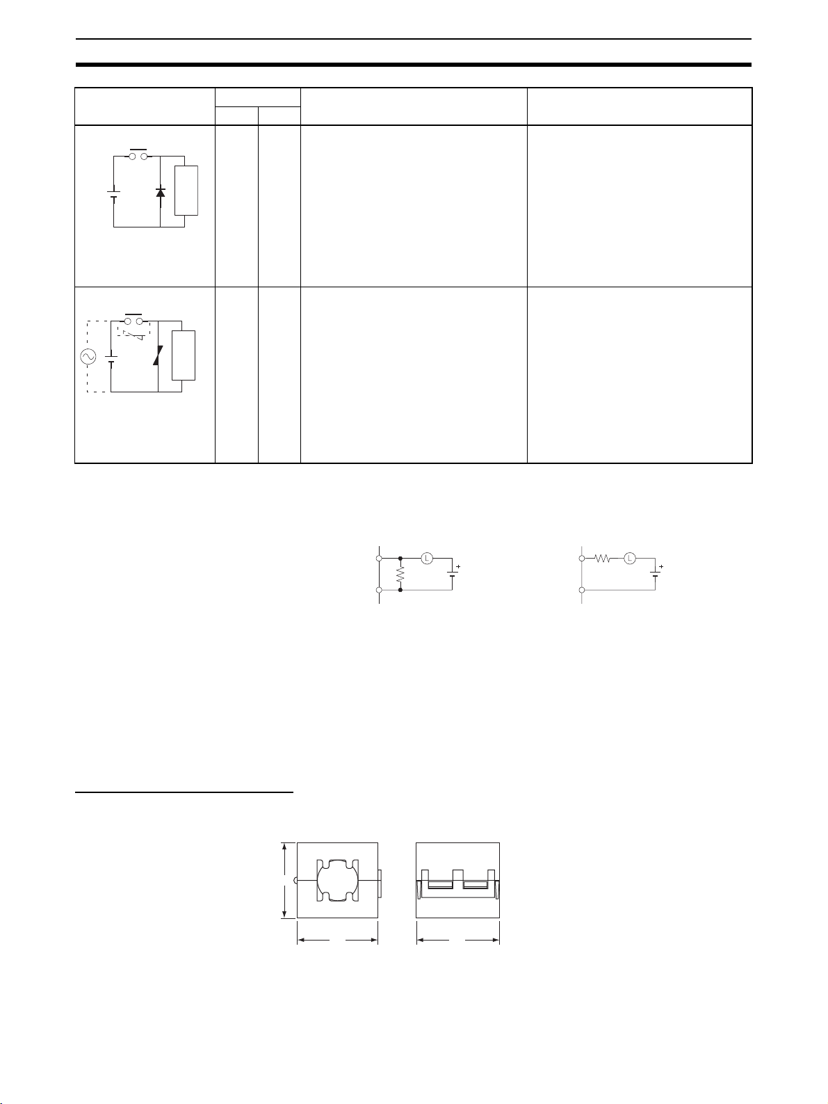
When switching an inductive load, co nne ct a n su r ge pr ot ec tor, diodes, etc., in
parallel with the load or contact as shown below.
Circuit Current Characteristic Required element
CR method
Powe r
supply
AC DC
Yes Yes If the load is a relay or soleno id, there is
C
R
Inductive
load
a time lag between the moment the circuit is opened and the moment the load
is reset.
If the supply voltage is 24 or 48 V , insert
the surge protector in parallel with the
load. If the supply voltage is 100 to
200 V, insert the surge protector
between the contacts.
The capacitance of the c apacitor must
be 1 to 0.5 µF per contact current of
1 A and resistance of the resistor must
be 0.5 to 1 Ω per contact v oltag e of 1V.
These values, however, vary with the
load and the characteristics of the
relay. Decide these values from experiments, and take into consideration that
the capacitance suppresses spark discharge when the contacts are separated and the resistance limits the
current that flows into the load when
the circuit is closed again.
The dielectric strength of the capacitor
must be 200 to 30 0 V. If the circ uit i s an
AC circuit, use a capacitor with no
polarity.
xxix
Page 29
Conformance to EC Directives 6
Circuit Current Characteristic Required element
AC DC
Diode method
Powe r
supply
Varistor method
Power
supply
No Yes The diode connected in parallel with
the load changes energy accumulated
by the coil into a current, which then
flows into the coil so tha t the current will
be converted into Joule heat by the
Inductive
load
resistance of the inductive load.
This time lag, betw een the m om ent the
circuit is opened and the moment the
load is reset, caused by this method is
longer than that caused by the CR
method.
Yes Yes The varistor method prevents the impo-
sition of high voltage between the contacts by using the constant voltage
characteristic of the varistor. There is
time lag between the moment the cir-
Inductive
load
cuit is opened and the moment the load
is reset.
If the supply voltage is 24 or 48 V , insert
the varistor in parallel with the load. If
the supply voltage is 100 to 200 V,
insert the varistor between the contacts.
The reversed dielectric strength value
of the diode must be at least 10 times
as large as the circuit voltage value.
The forward current of the diode must
be the same as or larger than the load
current.
The reversed dielectric strength value
of the diode may be two to three times
larger than the supply voltage if the
surge protector is applied to electronic
circuits with low circuit voltages.
---
When switching a load with a high inr ush current such as an incandescent
lamp, suppress the inrush current as shown below.
Countermeasure 1
OUT
R
COM
Providing a dark current of
approx. one-third of the rated
value through an incandescent
lamp
Countermeasure 2
R
OUT
COM
Providing a limiting resistor
6-5 Conditions for Meeting EMC Directives when Using CPM1A Relay
Expansion I/O Units
EN61131-2 immunity testing conditions when using the CPM1A-40EDR or
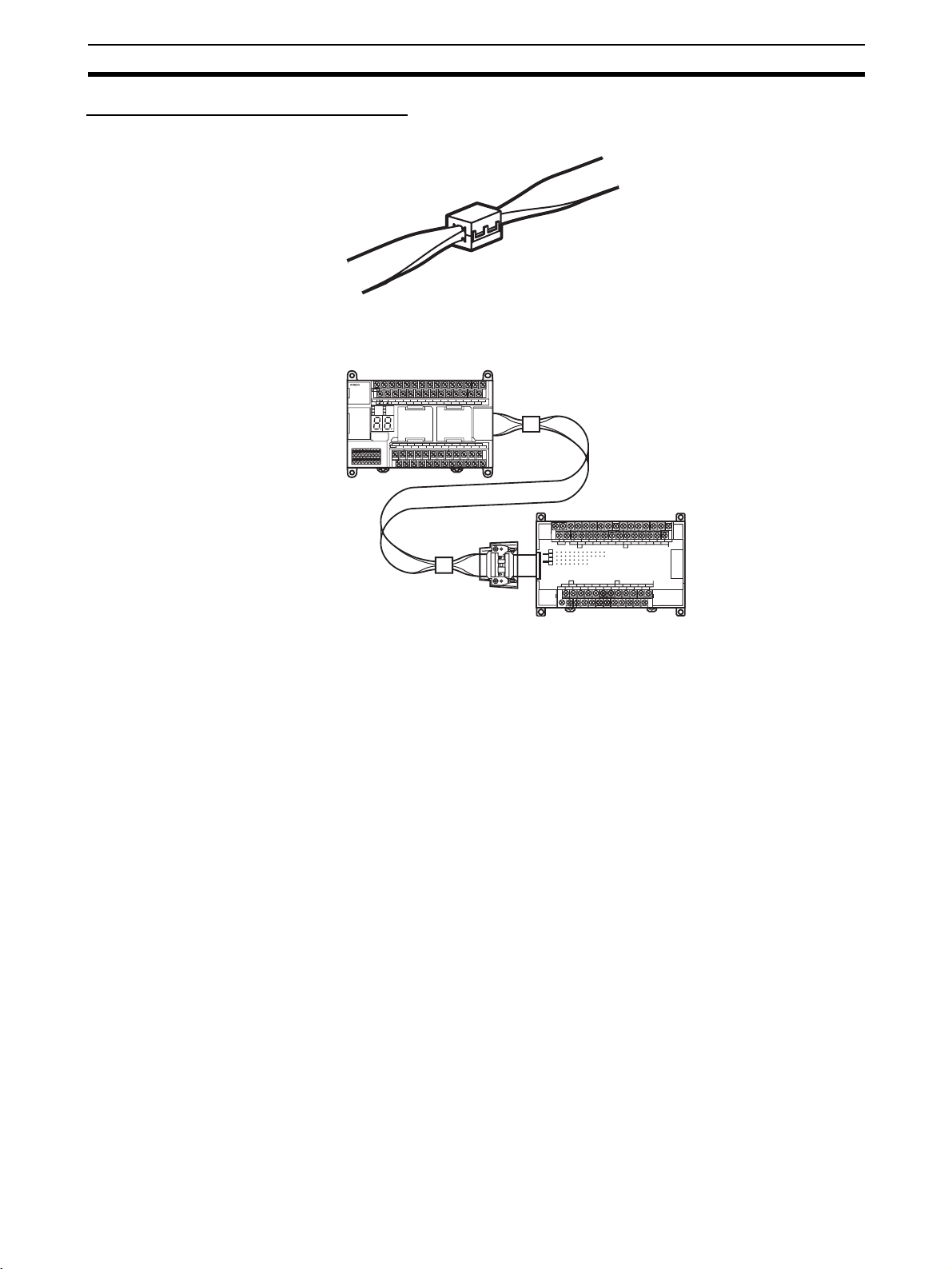
CPM1A-16ER with a CP1W-CN811 I/O Connecting Cable are given be low.
Recommended Ferrite Core
Ferrite Core (Data Line Filter) : 04 43-164151 manufactured by Nisshin Electric
Minimum impedance: 90 Ω at 25 MHz, 160 Ω at 100 MHz
30
xxx
32 33
Page 30
Conformance to EC Directives 6
Recommended Connection Method
1,2,3... 1. Cable Connection Method
2. Connection Method
As shown below, connect a ferrite core to each end of the CP1W-CN811
I/O Connecting Cable.
SYSMAC
IN
CP1H
AC100-240V
L1 L2/N COM 01 03 05 07 09 11 01 03 05 07 09 11
BATTERY
00 02 04 06 08 10 00 02 04 06 08 10
POWER
PERIPHERAL
ERR/ALM
BKUP
MEMORY
00 01 02 03 04 06 00 01 03 04 06
COM COM COM COM 05 07 COM 02 COM 05 07
100CH 101CH
OUT
EXP
1CH
NCNCNC
COM
01 03 05 07 09 11 01 03 05 07 09 11
NC
00 02 04 06 08 10
CH CH
CH
IN
CH
CH
0706050403020100
OUT
CH
0706050403020100
CH CH
NC
00 01 02 04 05 07 00 02 04 05 07
NC
COM COM COM COM COM COM03 06 01 03 06
111009080706050403020100
111009080706050403020100
00 02 04 06 08 10
40EDR
EXP
xxxi
Page 31

Conformance to EC Directives 6
xxxii
Page 32

SECTION 1
Features and System Configuration
This section introduces the features of the CP1H and describes its configuration. It also describes the Units that are available
and connection methods for the CX-Programmer and other peripheral devices.
1-1 Features and Main Functions . . . . . . . . . . . . . . . . . . . . . . . . . . . . . . . . . . . . . 2
1-1-1 CP1H Overview . . . . . . . . . . . . . . . . . . . . . . . . . . . . . . . . . . . . . . . . 2
1-1-2 Features. . . . . . . . . . . . . . . . . . . . . . . . . . . . . . . . . . . . . . . . . . . . . . . 6
1-2 System Configuration . . . . . . . . . . . . . . . . . . . . . . . . . . . . . . . . . . . . . . . . . . . 15
1-2-1 Basic System. . . . . . . . . . . . . . . . . . . . . . . . . . . . . . . . . . . . . . . . . . . 15
1-2-2 System Expansion. . . . . . . . . . . . . . . . . . . . . . . . . . . . . . . . . . . . . . . 17
1-2-3 System Expansion with CJ-series Units. . . . . . . . . . . . . . . . . . . . . . 20
1-2-4 Restrictions on System Configuration . . . . . . . . . . . . . . . . . . . . . . . 22
1-3 Connecting Programming Devices . . . . . . . . . . . . . . . . . . . . . . . . . . . . . . . . . 24
1-3-1 Connecting to a USB Port. . . . . . . . . . . . . . . . . . . . . . . . . . . . . . . . . 24
1-3-2 Connecting to a Serial Port. . . . . . . . . . . . . . . . . . . . . . . . . . . . . . . . 33
1-4 Function Charts . . . . . . . . . . . . . . . . . . . . . . . . . . . . . . . . . . . . . . . . . . . . . . . . 35
1-5 Function Blocks . . . . . . . . . . . . . . . . . . . . . . . . . . . . . . . . . . . . . . . . . . . . . . . 38
1-5-1 Overview of Function Blocks. . . . . . . . . . . . . . . . . . . . . . . . . . . . . . 38
1-5-2 Advantages of Function Blocks . . . . . . . . . . . . . . . . . . . . . . . . . . . . 38
1
Page 33

Features and Main Functions Section 1-1
1-1 Features and Main Functions
1-1-1 CP1H Overview
The SYSMAC CP1H is a n advanced high-speed, package-type Programmable Controller. While the CP1H employs the same architecture as the CS/CJ
Series and provides the same I/O capacity of 40 I/O points as the CPM2A, the
CP1H is approximately ten times faster.
There are three typ es of CP1H CPU Units to select from: a basi c CPU Unit
(X), a CPU Unit with built-in analog I/O terminals (XA), and a CPU Unit with
Dedicated Pulse I/O Terminals (Y).
Basic CPU Units: X The X CPU Units are the standard models in the CP1H Series.
24 built-in inputs (Functions
can be assigned.) (See note.)
Normal inputs (24)
Interrupt inputs (8)
Quick-response inputs (8)
16 built-in outputs (Functions
can be assigned.) (See note.)
Normal outputs (16)
High-speed counter
(4 axes)
100 kHz (single phase)
Unit Ver. 1.0 or Earlier Unit Ver. 1.1 or Later
2 pulse outputs
100 kHz
2 pulse outputs
30 kHz
4 pulse outputs
100 kHz
2 PWM outputs
2 PWM outputs
• The CPU Unit has 24 inputs and 16 outputs built in.
• High-speed counters and pulse outputs can be used on four axes with the
CPU Unit alone.
• The CP1H can be expanded to a maximum total of 320 I/O points by
using CPM1A Expansion I/O Units.
• Using CPM1A Expansion Units also allows extra functions (such as temperature sensor inputs) to be added.
• Installing an Option Board enables RS-232C and RS-422A/485 communications for Programmable Terminals, Bar Code Readers, Inverters, etc.
• Using CJ-seri es CPU B us Uni ts ena bles co mmunica tions with higher an d
lower level devices.
2
Page 34

Features and Main Functions Section 1-1
Note Settings in the PLC Setup dete rmine whether each input point is to be u sed
as a normal input, interrupt input, quick-response input, or high-speed
counter. The instruction used to control each output point determines whether
it is used as a normal output, pulse output, or PWM output.
CPU Units with Builtin Analog I/O
Terminals: XA
The XA CPU Unit adds analog I/O functionality to the X CPU Unit capabilities.
24 built-in inputs (Functions
can be assigned.) (See note.)
Normal inputs (24)
High-speed counter
(4 axes)
100 kHz (single phase)
Unit Ver. 1.0 and Earlier
2 pulse outputs
100 kHz
2 pulse outputs
30 kHz
2 PWM outputs
Unit Ver. 1.1 and Later
4 pulse outputs
100 kHz
2 PWM outputs
4 analog inputs
2 analog outputs
Interrupt inputs (8)
Quick-response inputs
(8)
16 built-in outputs (Functions
can be assigned.) (See note.)
Normal outputs (16)
• The CPU Unit has 24 inputs and 16 outputs built in.
• High-speed counters and pulse outputs can be used on four axes with the
CPU Unit alone.
• The CPU Unit has 4 analog voltage/curr ent inputs and 2 analog voltage/
current outputs built in.
• The CP1H can be expanded to a maximum total of 320 I/O points by
using CPM1A Expansion I/O Units.
• Using CPM1A Expansion Units also allows extra functions (such as temperature sensor inputs) to be added.
• Installing an Option Board enables RS-232C and RS-422A/485 communications for connecting to Programmable Term inals, Bar Code Readers,
Inverters, etc.
• Using CJ-seri es CPU B us Uni ts ena bles co mmunica tions with higher an d
lower level devices.
Note Settings in the PLC Setup dete rmine whether each input point is to be u sed
as a normal input, interrupt input, quick-response input, or high-speed
counter. The instruction used to control each output point determines whether
it is used as a normal output, pulse output, or PWM output.
3
Page 35

Features and Main Functions Section 1-1
CPU Unit with
Dedicated Pulse I/O
Terminals: Y
In place of the X CPU Units' more numerous built-in I/O points, the Y CPU
Unit provides dedicated pulse I/O terminals (1 MHz).
12 built-in inputs (Functions
Pulse inputs
2 high-speed counters
1 MHz (single phase)
Pulse outputs
2 pulse outputs
1 MHz
can be assigned.) (See note.)
Normal inputs (12)
Interrupt inputs (6)
Quick-response inputs
(6)
8 built-in outputs (Functions
can be assigned.) (See note.)
Normal outputs (8)
High-speed counter
(2 axes)
100 kHz (single phase)
2 pulse outputs
100 kHz
2 PWM outputs
• The CPU Unit has 12 inputs and 8 outputs built in.
• High-speed counters and pulse outputs can be used on four axes with the
CPU Unit alone.
The CPU Unit provides a h igh-speed pulse output of up to 1 MHz, and
can handle linear servos.
• The CP1H can be expanded to a maximum total of 300 I/O points by
using CPM1A Expansion I/O Units.
• Using CPM1A Expansion Units also allows extra functions (such as temperature sensor inputs) to be added.
• Installing an Option Board enables RS-232C and RS-422A/485 communications for connecting to Programmable Term inals, Bar Code Readers,
Inverters, etc.
• Using CJ-seri es CPU B us Uni ts ena bles co mmunica tions with higher an d
lower level devices.
Note Settings in the PLC Setup dete rmine whether each input point is to be u sed
as a normal input, interrupt input, quick-response input, or high-speed
counter. The instruction used to control each output point determines whether
it is used as a normal output, pulse output, or PWM output.
4
Page 36

Features and Main Functions Section 1-1
CP1H CPU Unit Models
Model X CPU Units XA CPU Units Y CPU Units
CP1H-X40DR-A
(relay outputs)
Power supply 100 to 240 VAC
50/60 Hz
Program capacity 20K steps
Max. number of I/O points
320 300
(See note.)
Normal I/O I/O points 40 20
Input points 24 12
Input specifica-
24 VDC
tions
Interrupt or
8 max. 6 max.
quick-response
inputs
Output points 16 8
Output specifica-
Relay output Transis tor out-
tions
Highspeed
High-speed
counter inputs
4 axes, 100 kHz (single phase)/50 kHz (differential phases) 2 axes, 1 MHz
counter
inputs
Dedicated high-
None 2 axes, 1 MHz
speed counter
input terminals
Pulse outputs
Built-in I/O terminal allocation
Dedicated pulse
Unit version 1.0 and earlier: 2 axes; 100 kHz, 2 axes, 30 kHz
Unit version 1.1 and later: 4 axes, 100 kHz
None 2 axes, 1 MHz
output terminals
Built-in analog I/O None Analog voltage/current inputs: 4
CP1H-X40DT-D
(transistor
outputs,
CP1H-XA40DR-
A (relay
outputs)
sinking)
CP1H-X40DT1-
D (transistor
outputs,
sourcing)
24 VDC 100 to 240 VAC
50/60 Hz
Relay output Transistor out-
put
Analog voltage/current outputs: 2
CP1H-XA40DT-
D (transistor
outputs,
sinking)
CP1H-
XA40DT1-D
CP1H-Y20DT-D
(transistor
outputs,
sinking)
(to be released
soon)
(transistor
outputs,
sourcing)
24 VDC 24 VDC
Transistor out-
put
put
(single phase)/
50 kHz (differential phases)
(single phase)/
500 kHz (differential phases)
2 axes, 100 kHz
None
Note When CPM1A Expansion I/O Units are used.
Interpreting CP1H CPU Unit Model Numbers
Class
X: Basic model
XA: Built-in analog I/O terminals
Y: Dedicated pulse I/O terminals
Number of built-in
normal I/O points
40: 40
20: 20
Input classification
D: DC inputs
CP1H-@@@@@@-@
Power supply
A: AC
D: DC
Output classification
R: Relay outputs
T: Transistor outputs (sinking)
T1: Transistor outputs (sourcing)
5
Page 37

Features and Main Functions Section 1-1
k
1-1-2 Features
This section describes the main features of the CP1H.
Basic CP1H Configuration
CP1H CPU Unit (Example: XA)
CX-One
Two-digit 7-segment LED display
Input terminal bloc
Output terminal block
USB cable
Peripheral
USB port
Analog adjuster
External analog
settings input
Built-in analog
inputs
Built-in analog
outputs
(XA models only)
USB port
ON
123
4
Memory Cassette
Battery (CJ1W-BAT01)
Two Option Board slots
Faster Processing
Speed (All Models)
Option Board
CP1W-ME05M
Memory Cassette
One RS-232C port
CP1W-CIF01 RS-232C
Option Board
One RS-422A/485 port
CP1W-CIF11 RS-422A/485
Option Board
• Top-class performance has been achieved in a micro PLC, with an
instruction processing speed equivalent to the CJ1M.
• Approximately 500 instructions are processed at high speed.
• Program creation and contro l are simplifi ed by using function blocks (FB)
and tasks.
6
Page 38

Features and Main Functions Section 1-1
Full Complement of
High-speed Counter
Functions (All
Models)
High-speed counter inp uts can be enabled by connecting rota ry encoders to
the built-in inputs. The ample number of high-speed counter inputs ma kes it
possible to control a multi-axis device with a single PLC.
• X and XA CPU Units
Four 100-kHz (single phase)/50-kHz (differential phases) high-speed
counter inputs are provided as a standard feature. (See note.)
24 built-in inputs
(Functions can be assigned.)
High-speed counter
(4 axes)
100 kHz (single phase)
Note Settings in the PLC Setup determine whether each input point is to
be used as a normal input, interrupt input, quick-response input, or
high-speed counter.
• Y CPU Units
Along with two 100-kHz ( single phase)/50-k Hz (differential phases) highspeed counter inputs, two 1-MHz (single phase)/500-kHz (differential
phases) dedicated high-speed counter terminals are provided.
Dedicated pulse
inputs
Two high-speed
counters
1 MHz (for single phase)
12 built-in inputs
(Functions can be assigned.)
High-speed counter
(2 axes)
100 kHz (single phase)
Note Settings in the PLC Setup determine whether each input point is to
be used as a normal input, interrupt input, quick-response input, or
high-speed counter.
7
Page 39

Features and Main Functions Section 1-1
Full Complement of Highspeed Counter Functions
(All Models)
Versatile Pulse
Control (All Models)
High-speed Processing for High-speed Counter Present Value (PV)
Target Values or Range Comparison Interrupts
An interrupt ta sk can be star te d when the count r eaches a s pecified value or
falls within a specified range.
High-speed Counter Input Frequency (Speed) Monitoring
The input pulse fr equency can be moni tored using the PRV instruc tion (one
point only).
High-speed Counter PV Holding/Refreshing
It is possible to toggle between holding and refreshing the high-speed counter
PV by turning ON and OFF the High-speed Counter Gate Flag from the ladder
program.
Positioning and speed control by a pulse-in put servo driver is enabled by outputting fixed duty ratio p ulse output signals fr om the CPU Unit's built-in o utputs.
Four axes (X,Y, Z, and
θ) can be controlled. A 1 -M Hz s pee d pu ls e rate i s als o
possible for Y CPU Units.
• X and XA CPU Units
Pulse outputs for 4 axes at 10 0 kHz maximum ar e provided as st andard
features. (See note.) (Unit version 1.0 or earlier: Pulse outputs for 2 axes
at 100 kHz maximum and 2 axes at 30 kHz maximum.)
16 built-in inputs
(Functions assigned.)
Unit Ver. 1.0 or Earlier
2 pulse outputs
100 kHz
2 pulse outputs
30 kHz
Unit Ver. 1.1 or Later
4 pulse outputs
100 kHz
Note The instruction used to control each output point determines
whether it is used as a normal output, pulse output, or PWM output.
8
Page 40

Features and Main Functions Section 1-1
• Y CPU Units
Along with pulse outputs for two axes at 100 kHz maximum, dedicated
pulse output ter minals for two axes at 1 MHz are provided as standard
features. (See note.)
High-speed, high-p recision positioning by linear ser vomotor, d irect drive
motor, etc., is enabled using 1-MHz pulses.
Full Complement of Pulse
Output Functions (All
Models)
Dedicated pulse
outputs
2 pulse outputs
1 MHz
8 built-in I/O points
(Functions assigned)
2 pulse outputs
100 kHz
Note The instruction used to control each output point determines
whether it is used as a normal output, pulse output, or PWM output.
Select CW/CCW Pulse Outputs or Pulse Plus Direction Outputs for the
Pulse Outputs
The pulse outputs ca n be selected to m atch the pulse in put specification s of
the motor driver.
Easy Positioning with Absolute Coordinate System Using Automatic
Direction Setting
For operations in an absolute coordinate system (i.e., when the origin is
established or when the PV is ch anged by the INI instruc tion), the CW/CCW
direction can be automatically set when PULSE OUTPUT instructions are
executed according to whether the specifie d numbe r of output pulses i s more
or less than the pulse output PV.
Triangular Control
If the amount of output puls es required for acce leration and deceleration (th e
target frequency times the time to reach the target frequency) exceeds the
preset target number of output pulses during positioning (when the ACC
instruction in independent mode or the PLS2 instruction is executed), the
acceleration and d eceleration will be s hor tened and trian gular control w ill be
executed instead of trapezoidal control. In other words, the trapezoida l pulse
output will be eliminated, with no period of constant speed.
Target Position Changes during Positioning (Multiple Start)
While positioning using a PUL SE OUTPU T (PLS2) ins tructio n is in progre ss,
the target position, targe t speed, accelerati on rate, and deceleration rate can
be changed by executing another PLS2 instruction.
Positioning Changes during Speed Control (Interrupt Feeding)
While speed control in continuous mode is in effect, it is possible to change to
positioning in independent mode by executing a PULSE OUTPUT (PLS2)
instruction . By this means, int errupt feedin g (moving a spe cified am ount) ca n
be executed under specified conditions.
9
Page 41

Features and Main Functions Section 1-1
T ar get Speed, Acceleration Rate, and Deceleration Rat e Changes during
Acceleration or Deceleration
When a PULSE OUTPU T instr uct ion with trapezoidal acc elerat ion and de celeration is executed (for speed control or positioning), the target speed and
acceleration and deceleration rates can be changed during acceleration or
deceleration.
Lighting and Power Control by Outputting Variable Duty Ratio Pulses
Operations, such as lighting and power con trol, can be handl ed by outputting
variable duty ratio pulse (PWM) output signals from the CPU Unit's built-in
outputs.
Origin Searches (All
Models)
Input Interrupts (All
Models)
Note For each input point, a selection in the PLC Setup dete rm ines whether it is to
Quick-response
Inputs (All Models)
Note For each inp ut, a PL C Setu p pa r ame ter det ermines whe the r i t is t o be used as
Origin Search and Origin Return Operations Using a Single Instruction
An accurate origi n s ear c h co mb ini ng all I/O si gnals (origin pr oximity input signal, origin input sign al, positioning compl eted signal, error counte r reset output, etc.) can be executed with a sin gl e ins truction. It is also pos s ible to move
directly to an established origin using an origin return operation.
In direct mode, an interrupt task can be started when a built-in input tur ns ON
or OFF. In counter m ode, the rising or falling edges of built-in inputs can be
counted, and an interrupt task started when the count reaches a specified
value. The maximum number of points i s 8 for X and XA CPU Unit s and 6 for
Y CPU Units. (See note.)
be used as a normal input, interrupt input, quick-response input, or highspeed counter. The interrupt input re sponse frequ ency in count er mode must
be 5 kHz or less total for all interrupts.
By using quick-response i nputs, built-in inputs up to a minimum input signal
width of 30
µs can be read regardless of the cycle time.
The maximum number of points is 8 for X and XA CPU Units and 6 for Y CPU
Units. (See note.)
a normal input, interrupt input, quick-response input, or high-speed counter.
Analog I/O Function
(XA CPU Units Only)
10
XA CPU Units have analog I/O functionality, with 4 analog voltage/current
inputs and 2 analog voltage/current outputs built in.
4 analog inputs
ON
123
4
0 to 5 V, 1 to 5 V,
0 to 10 V, −10 to 10 V
0 to 20 mA, 4 to 20 mA
Inverter, etc.
2 analog outputs
0 to 5 V, 1 to 5 V,
0 to 10 V, −10 to 10 V
0 to 20 mA, 4 to 20 mA
• A wide range of applications is possible at a resolution of 6,000 or 12,000.
• Application is also possible for process-control sensor input or Inverter
control without using Expansion I/O Units.
Page 42

Features and Main Functions Section 1-1
Analog Settings (All Models)
Changing Settings Using
Analog Adjustment
Changing Settings Using
External Analog Setti ng
Inputs
By adjusting the analog adjuster with a Phillips screwdriver, the value in the
Auxiliary Area can be changed to any value between 0 and 255. This makes it
easy to change s et values s uc h as t ime rs and counters without Programming
Devices.
Phillips screwdriver
Analog adjuster
Turning the control on the CP1H changes the
Ladder program
CNTX
A642
Example: The production quantity could be changed by
changing the counter set value from 100 to 150.
PV in A642 between 0000 and 0255 (00 and
FF hex).
(During the adjustment, the value in A642 is
displayed from 00 to FF on the 7-segment
display.)
External analo g values of 0 to 10 V (resolution: 256) are converted to digital
values and stored in a word in the AR Area. This enables applications that
require on-site adjustme nt of settings that do not d emand a par ticularly high
degree of accuracy, suc h as for example, a setting based on changes in outdoor temperatures or potentiometer inpu ts.
External analog setting
input connector
Potentiometer,
temperature sensor, etc.
0 to 10 V
Ladder program
TIMX
A643
Example: The production quantity could be changed by
changing the timer set value from 100 to 150.
When a voltage (0 to 10 V) is input
from a device such as a potentiometer
to the external analog setting input, the
PV in A643 is refreshed between 0000
and 0100 hex (0 to 256).
11
Page 43

Features and Main Functions Section 1-1
Connectability with Various Components (All Models)
USB Port for
Programming Devices
Expansion Capability for
Two Serial Ports (All
Models)
CX-One Suppor t Software, such as the CX-Programmer, connects from the
USB port on a computer to the CP1H built-in peripheral USB port via commercially available USB cable.
Personal computer
CX-One (ver. 1.1 or higher)
(e.g., CX-Programmer ver. 6.1 or higher)
USB port
IN
USB cable
Peripheral
USB port
L1 L2/N COM 01 03 05 07 09 11 01 03 05 07 09 11
00 02 04 06 08 10 00 02 04 06 08
POWER
ERR/ALM
BKUP
00 01 02 03 04 06 00 01 03 04 06
COM COM COM COM 05 07 COM 02 COM 05
100CH 101CH
OUT
10
EXP
07
1CH
A maximum of two Serial Co mmunications Boards each with one R S-232C
port or one RS-422A/485 por t c an be a dde d. W ith a tota l o f up to thr ee ports,
including the USB por t, this makes it possible to simultaneously connect a
computer, PT, CP1H, and/or various compo nents, such as an Inverter, Temperature Controller, or Smart Sensor.
NS-series PT, personal computer, bar code reader, etc.
RS-232C
CP1H
ON
123
4
CP1W-CIF01 RS-232C
Option Board
CP1W-CIF11 RS-422A/485
Option Board
RS-422A
Inverter, etc. (See note 1.)
CP1H (or CJ1M)
(See note 2.)
12
Page 44

Features and Main Functions Section 1-1
r
Note (1) The Modbus-RTU easy master (available for all models) makes it easy to
control Modbus Slaves (such as Inverters) with serial communications.
After the Modbus Slave address, function , a nd data have been preset in
a fixed memory ar ea ( DM), message s ca n b e sen t or re ceived in dependently of the program by turning software switches.
Communications can be executed independently of
the program by setting a Modbus-RTU command in
the DM and turning ON a software switch.
Modbus-RTU
Inverte
(2) By using the serial PLC Links (available for all models), a maximum of 10
words of data per CPU Unit can be shared independently of the program
among a maximum of nine CPU Units (CP1H -CP1H-CJ1M) using RS422A/485 Option Boards.
7-segment LED
Display (All Models)
SYSMAC
IN
CP1H
0CH 1CH
L1 L2/N COM
01 03 05 07 09 11 01 03 05 07 09 11
BATTERY
00 02 04 06 08 10 00 02 04 06 08
POWER
RUN
PERIPHERAL
ERR/ALM
INH
BKUP
PRPHL
MEMORY
OUT
Data sharing
COMM COMM
00 01 02 03 04 06 00 01 03 04 06
COM COM COM COM 05 07 COM 02 COM 05
100CH 101CH
10
CP1H CPU Unit
EXP
(Master)
07
SYSMAC
IN
CP1H
L1 L2/N COM 01 03 05 07 09 11 01 03 05 07 09 11
BATTERY
00 02 04 06 08 10 00 02 04 06 08
POWER
PERIPHERAL
ERR/ALM
BKUP
COMM
MEMORY
00 01 02 03 04 06 00 01 03 04 06
COM COM COM COM 05 07 COM 02 COM 05
100CH 101CH
OUT
RS-422A/485
CP1H CPU Unit
(Slave)
10
EXP
07
1CH
SYSMAC
IN
CP1H
L1 L2/N COM 01 03 05 07 09 11 01 03 05 07 09 11
BATTERY
00 02 04 06 08 10 00 02 04 06 08
POWER
PERIPHERAL
ERR/ALM
BKUP
COMM
MEMORY
00 01 02 03 04 06 00 01 03 04 06
COM COM COM COM 05 07 COM 02 COM 05
100CH 101CH
OUT
CP1H CPU Unit
(Slave)
10
EXP
07
1CH
CJ1M CPU Unit
(Slave)
8 CPU Units max.
A two-digit 7-segment LED display makes it easy to monitor PLC status.
This improves the human-machine interface for maintenance, making it easier
to detect troubles that may occur during machine operation.
2-digit 7-segment LED display
• Displays error codes and details for errors detected by the CPU Unit.
13
Page 45

Features and Main Functions Section 1-1
g
• Displays the progress of transfers between the CPU Unit and Memory
Cassette.
• Displays changes in values when using the analog control.
• Displays user-defined co des from special display instr uctions in the ladder program.
No-battery Operation
(All Models)
Memory Cassettes
(All Models)
Programs, the PLC Setup, and other data can be aut omatically saved to the
CPU Unit's built-in flash memor y. Moreover, DM Area data can be saved to
the flash memory and then used as initial data when the power is turned ON.
This allows programs and initi al values (such a s recip e se tup data ) in the D M
Area to be saved in the CPU Unit without the need to maintain a backup battery.
CP1H CPU Unit
SYSMAC
IN
CP1H
0CH 1CH
L1 L2/N COM
BATTERY
PERIPHERAL
Pro
01 03 05 07 09 11 01 03 05 07 09 11
00 02 04 06 08 10 00 02 04 06 08
POWER
RUN
ERR/ALM
INH
BKUP
PRPHL
Built-in flash
memory
MEMORY
00 01 02 03 04 06 00 01 03 04 06
COM COM COM COM 05 07 COM 02 COM 05
100CH 101CH
OUT
10
EXP
07
rams, DM initial values, etc.
Data saving capability
without a battery
Built-in flash memor y data, such as pro grams and DM initial-value data, can
be stored on a Memor y Cassette (opti onal) as backup data. In addit ion, programs and initial-value data can be easily c opied to another CPU Unit usin g
the Memory Cassette to recreate the same system.
CP1H CPU Unit Another CP1H CPU Unit
SYSMAC
IN
CP1H
0CH 1CH
L1 L2/N COM
BATTERY
Built-in flash
POWER
RUN
PERIPHERAL
ERR/ALM
INH
BKUP
PRPHL
memory
MEMORY
01 03 05 07 09 11 01 03 05 07 09 11
00 02 04 06 08 10 00 02 04 06 08
00 01 02 03 04 06 00 01 03 04 06
COM COM COM COM 05 07 COM 02 COM 05
100CH 101CH
OUT
10
EXP
07
Memory
Cassette
MEMORY
SYSMAC
IN
CP1H
0CH 1CH
L1 L2/N COM
01 03 05 07 09 11 01 03 05 07 09 11
BATTERY
00 02 04 06 08 10 00 02 04 06 08
POWER
RUN
PERIPHERAL
ERR/ALM
INH
BKUP
PRPHL
MEMORY
00 01 02 03 04 06 00 01 03 04 06
COM COM COM COM 05 07 COM 02 COM 05
100CH 101CH
OUT
Can be automatically
transferred at startup.
10
EXP
07
Programs, DM initial values, etc.
Security (All Models) A password registration function is provided for the CPU Unit to prevent unau-
thorized copy of ladder programs. If an attempt is ma de to read a ladder program from a CX-Programmer, access to the program is denied if the password
that is entered does not match the registered password. If incorrect passwords are entered for five consecutive attempts, the CPU Unit does not
accept any more passwords for two hours.
14
Page 46

System Configuration Section 1-2
Expansion Capability
for CJ-series Special
I/O Units and CPU
A maximum of two CJ-ser ies S pec ia l I/ O U nit s or CPU Bus Units ca n b e c onnected via a CJ Unit Ada pter. It is also possible to con nect to u pper l evel and
lower level networks, and to expand the system by using analog I/O.
Bus Units (All
Models)
SYSMAC
IN
CP1H
L1 L2/N COM 01 03 05 07 09 11 01 03 05 07 09 11
BATTERY
POWER
PERIPHERAL
ERR/ALM
BKUP
MEMORY
1-2 System Configuration
1-2-1 Basic System
SYSMAC
CP1H
BATTERY
PERIPHERAL
IN
0CH 1CH
L1 L2/N COM
POWER
RUN
ERR/ALM
INH
BKUP
PRPHL
CP1W-EXT01
CJ Unit Adapter
00 02 04 06 08 10 00 02 04 06 08
00 01 02 03 04 06 00 01 03 04 06
COM COM COM COM 05 07 COM 02 COM 05
100CH 101CH
OUT
10
EXP
07
1CH
Can be expanded by connecting two CJ-series
CPU Bus Units and/or Special I/O Units.
01 03 05 07 09 11 01 03 05 07 09 11
00 02 04 06 08 10 00 02 04 06 08
CJ1W-TER01 CJ-series End Cover
(Included with CJ Unit Adapter.)
DIN T rac k
10
EXP
MEMORY
00 01 02 03 04 06 00 01 03 04 06
COM COM COM COM 05 07 COM 02 COM 05
100CH 101CH
OUT
07
Maximum Number of Normal I/O Points
Type Description Power supply
voltage
X Basic CPU Units 100 to 240 VAC CP1H-X40DR-A 24 DC inputs 16 relay outputs 740 g max.
24 VDC CP1H-X40DT-D 16 transistor (sink-
XA CPU Units with
built-in analog I/O
terminals
Y CPU Unit with ded-
100 to 240 VAC CP1H-XA40DR-A 16 relay outputs 740 g max.
24 VDC CP1H-XA40DT-D 16 transistor (sink-
24 VDC CP1H-Y20DT-D 12 DC inputs 8 transistor (sinking)
icated pulse I/O
terminals
Model Normal built-in
inputs
Normal built-in
outputs
ing) outputs
CP1H-X40DT1-D 16 transistor (sourc-
ing) outputs
ing) outputs
CP1H-XA40DT1-D 16 transistor (sourc-
ing) outputs
outputs
Weight
590 g max.
590 g max.
590 g max.
590 g max.
560 g max.
15
Page 47

System Configuration Section 1-2
Optional Products
Item Model Specifications Weight
Memory
Cassette
CP1W-ME05M Can be used to store user programs in
flash memory, parameters, DM initial
values, comment memory, FB programs, and data in RAM.
10 g max.
Serial
Communications
Expansion
When serial communicati ons are re qui red for a CP1H CPU Unit, an RS-232 C
or RS-422A/485 Option Board can be added.
This enables connection by serial communications to NS-series PTs, Bar
Code Readers, components s uch as Inverters, and computers without USB
ports (such as when using the CX-Programmer).
NS-series PT, personal computer, bar code reader, etc.
CP1W-CIF01 RS-232C
Option Board
RS-232C
(Expansion)
CP1W-CIF11 RS-422A/485C
Option Board
RS-422A (Expansion)
Inverter, etc.
Option Boards for Ser ial Communications
Appearance Name Model Port Serial communications modes
COMM
COMM
RS-232C
Option Board
RS-422A/485
Option Board
CP1W-CIF01 One RS-232C port
(D-Sub, 9 pins,
female)
CP1W-CIF11 One RS-422A/485
port (terminal block
for ferrules)
Host Link, NT Link (1: N mode),
No-protocol, Serial PLC Link
Slave, Serial P LC Link Mas ter,
Serial Gateway (conversion to
CompoWay/F, conversion to Modbus-RTU), peripheral bus
16
Page 48

System Configuration Section 1-2
Unit Consumption
Currents
Unit Model Current consumption External power supply
5 V DC 24 V DC
CPU Unit CP1H-XA40DR-A 0.430 A 0.180 A 0.3 A max.
CP1H-XA40DT-D 0.510 A 0.120 A --CP1H-XA40DT1-D 0.510 A 0.150 A --CP1H-X40DR-A 0.420 A 0.070 A 0.3 A max.
CP1H-X40DT-D 0.500 A 0.010 A --CP1H-X40DT1-D 0.500 A 0.020 A --CP1H-Y20DT-D 0.55 A --- ---
Note (1) The current consumption of the following is included with the current con-
sumption of the CPU Unit: CP1W-ME05M Memory Cassette, CP1W-CIF1 or CP1W-CIF11 Option Board, and CP1W-EXT01 CJ Unit Adapter.
(2) CPU Units taking a DC power supply do not provide an external power
supply.
1-2-2 System Expansion
A maximum of seven CPM1A Expans ion Uni ts or E xp ans ion I/O Units can be
connected to a CP1H CPU Unit.
This allows for the expansion of various functi ons such as I/O poi nts or temperature sensor inputs.
CP1H CPU Unit
SYSMAC
IN
CP1H
L1 L2/N COM 01 03 05 07 09 11 01 03 05 07 09 11
BATTERY
00 02 04 06 08 10 00 02 04 06 08
POWER
PERIPHERAL
ERR/ALM
BKUP
MEMORY
00 01 02 03 04 06 00 01 03 04 06
COM COM COM COM 05 07 COM 02 COM 05
100CH 101CH
OUT
10
EXP
07
1CH
A maximum of 7 CPM1A-series Expansion
I/O Units or Expansion Units can be added.
When CP1W-CN811 I/O Connecting Cable is us ed, the cable length can be
extended by up to 80 cm, enabling installing the Units in two rows.
CP1W-CN811
I/O Connecting Cable
CP1H CPU Unit
SYSMAC
IN
CP1H
L1 L2/NCOM010305070911010305070911
BATTERY
00 02 04 06 08 10 00 02 04 06 08
POWER
PERIPHERAL
ERR/ALM
BKUP
MEMORY
00 01 02 03 04 06 00 01 03 04 06
COM COM COM COM 05 07 COM 02 COM 05
100CH 101CH
OUT
10
EXP
07
1CH
DIN T rac k
Up to seven Units can be added, and the maximum numbe r of I/O p oints per
Unit is 40, so the maximum total number of expansion I/O points is 280.
17
Page 49

System Configuration Section 1-2
Maximum Normal I/O Points
Type Power
X
(Basic CPU
Units)
XA
(CPU Units with
built-in analog
I/O terminals)
Y
(CPU Unit with
dedicated pulse
I/O terminals)
supply
voltage
100 to
240 V AC
24 VDC CP1H-X40DT-D 16 transistor out-
100 to
240 V AC
24 VDC CP1H-XA40DT-D 16 transistor out-
24 VDC CP1H-Y20DT-D 12 DC
Model Built-in
normal
Built-in normal
outputs
inputs
CP1H-X40DR-A 24 DC
16 relay outputs 7 280
inputs
puts (sinking)
CP1H-X40DT1-D 16 transistor out-
puts (sourcing)
CP1H-XA40DR-A 16 relay outputs
puts (sinking)
CP1H-XA40DT1-D 16 transistor out-
puts (sourcing)
8 transistor out-
inputs
puts (sinking)
Max.
number of
Expansion
I/O Units
Max.
number of
expansion
points
(7 Units ×
40 points)
Max. total
I/O points
320
300
CPM1A Expansion I/O Units
Appearance Model Normal
inputs
CPM1A-40EDR 24 VDC:
CPM1A-40EDT 16 transis tor outputs (sink-
24 inputs
CPM1A-40EDT1 16 transistor outputs (sourc-
Normal outputs Weight
16 relay outputs 380 g max.
320 g max.
ing)
ing)
COM 01 03 05 07 09 11
NC 00 02 04 06 08 10
CH
IN
CH
00 01 02 03
04 05 06 07
08 09 10 11
OUT
CH
00 01 02 03 04 05 06 07
CH
NC 00 01 02 04 05 07
NC COM COM COM 03 COM 06
01COM 03
00 02
IN
CH
00 01 02 03
08 09 10 11
04 06
COM 05 07
CPM1A-20EDR1 24 VDC:
CPM1A-20EDT 8 transistor outputs (sinking)
EXP
CPM1A-20EDT1 8 transistor outputs (sour c-
12 inputs
8 relay outputs 300 g max.
ing)
CPM1A-16ER None 16 relay outputs 280 g max.
CPM1A-8ED 24 VDC:
None 200 g max.
8 inputs
CPM1A-8ER None 8 relay outputs 250 g max.
EXP
CPM1A-8ET 8 transistor outputs (sinking)
CPM1A-8ET1 8 trans is tor out puts (sour c-
ing)
18
Page 50

System Configuration Section 1-2
CPM1A Expansion Units
Name and
appearance
Analog I/O Units CPM1A-MAD01 2 analog
COM 01 03 05 07 09 11
NC 00 02 04 06 08 10
CH
IN
CH
00 01 02 03
04 05 06 07
08 09 10 11
OUT
CH
00 01 02 03 04 05 06 07
CH
EXP
NC 00 01 02 04 05 07
NC COM COM COM 03 COM 06
Temperature
Sensor Units
COM 01 03 05 07 09 11
NC 00 02 04 06 08 10
CH
IN
CH
00 01 02 03
04 05 06 07
08 09 10 11
OUT
CH
00 01 02 03 04 05 06 07
CH
EXP
NC 00 01 02 04 05 07
NC COM COM COM 03 COM 06
Model Specifications Weight
inputs
1 analog
output
CPM1A-MAD11 2 analog
inputs
0 to 10 V/1 to 5 V/4
to 20 mA
0 to 10 V/−10 to
+10 V/4 to 20 mA
0 to 5 V/1 to 5 V/0 to
10 V/−10 to +10 V/0
Resolution: 256
Resolution: 6,000
to 20 mA/4 to 20 mA
1 analog
output
1 to 5/0 to 10 V/−10
to +10 V/0 to 20 mA/
4 to 20 mA
CPM1A-AD041 4 analog
inputs
0 to 5 V/1 to 5 V/0 to
10 V/−10 to +10 V/
Resolu-
tion: 6,000
0 to 20 mA/
4 to 20 mA
CPM1A-DA041 4 analog
outputs
1 to 5 V/0 to 10 V/
−10 to +10 V/
0 to 20 mA/
4 to 20 mA
CPM1A-TS001 2 inputs Thermocouple input
CPM1A-TS00 2 4 inputs
K, J
CPM1A-TS101 2 inputs Platinum resis tance thermometer
CPM1A-TS10 2 4 inputs
input
Pt100, JPt100
150 g max.
200 g max.
250 g max.
DeviceNet I/O
Link Unit
COM 01 03 05 07 09 11
NC 00 02 04 06 08 10
CH
IN
CH
00 01 02 03
04 05 06 07
08 09 10 11
OUT
CH
00 01 02 03 04 05 06 07
CH
EXP
NC 00 01 02 04 05 07
NC COM COM COM 03 COM 06
CompoBus/S
I/O Link Unit
COM 01 03 05 07 09 11
NC 00 02 04 06 08 10
CH
IN
CH
00 01 02 03
04 05 06 07
08 09 10 11
OUT
CH
00 01 02 03 04 05 06 07
CH
EXP
NC 00 01 02 04 05 07
NC COM COM COM 03 COM 06
CPM1A-DRT21 As a DeviceNet Slave, 32 inputs and 32 out-
puts are allocated.
CPM1A-SRT21 As a CompoBus/S slave, 8 inputs and 8 out-
puts are allocated.
200 g max.
200 g max.
19
Page 51

System Configuration Section 1-2
Number of Allocated Words and Current Consumption for Expansion Units and Expansion I/O Units
Unit Model Number of allocated
Expansion I/O Units 40 I/O points
24 inputs
16 outputs
20 I/O points
12 inputs
8 outputs
16 outputs CPM1A-16ER None 2 0.042 A 0.090 A
8 inputs CPM1A-8ED 1 No ne 0.018 A --8 outputs CPM1A-8ER None 1 0.026 A 0.044 A
Expansion
Units
Analog I/O Units A/D: 2 points
D/A: 1 point
Temperature
Sensor Units
Thermocouple
inputs
K/J
Platinum resistance inputs
Pt/JPt
CompoBus/S
I/O Link Unit
DeviceNet I/O
Link Unit
8 inputs
8 outputs
32 inputs
32 outputs
words
Input Output 5 VDC 24 VDC
CPM1A-40EDR 2 2 0.080 A 0.090 A
CPM1A-40EDT 0.160 A --CPM1A-40EDT1
CPM1A-20EDR1 1 1 0.103 A 0.044 A
CPM1A-20EDT 0.130 A --CPM1A-20EDT1
CPM1A-8ET 0.075 A --CPM1A-8ET1
CPM1A-MAD01 2 1 0.066 A 0.066 A
CPM1A-MAD11 0.083 A 0.110 A
CPM1A-TS001 2 None 0.040 A 0.059 A
CPM1A-TS002 4
CPM1A-TS101 2 0.054 A 0.073 A
CPM1A-TS102 4
CPM1A-SRT21 1 1 0.029 A ---
CPM1A-DRT21 2 2 0.048 A ---
Current
consumption (mA)
1-2-3 System Expansion with CJ-series Units
A maximum of two CJ-ser ies S pec ia l I/ O U nit s or CPU Bus Units ca n b e c onnected. In order to connect them, a CP1W-EXT01 CJ Unit Adapter and a
CJ1W-TER01 End Cover are required. These Units make it possible to add
serial communic ation functio ns, such as network communica tions or pr otocol
macros.
PFP-M
End Plates
DIN T rac k
SYSMAC
IN
CP1H
L1 L2/N COM 01 03 05 07 09 11 01 03 05 07 09 11
BATTERY
00 02 04 06 08 10 00 02 04 06 08
POWER
PERIPHERAL
ERR/ALM
BKUP
MEMORY
00 01 02 03 04 06 00 01 03 04 06
COM COM COM COM 05 07 COM 02 COM 05
100CH 101CH
OUT
CP1W-EXT01
CJ Unit Adapter
10
EXP
07
1CH
CJ-series
CPU Bus Units
Special I/O Units
CJ-series
CJ1W-TER01 End Cover
(Included with CJ Unit
Adapter.)
20
Page 52

System Configuration Section 1-2
Required Units
Name Model Description Weight
CJ Unit Adapter CP1W-EXT01 Mounting a CJ Unit Adapter to the right of the
CP1H CPU Unit makes it possible to connect up
to two CJ-series Special I/O Units or CPU Bus
Units.
Note The CJ Unit Adapter comes packaged
with one CJ1W-TER01 End Cover.
40 g max.
Main Connectable CJseries Units
Classification Unit name Model Current
CPU Bus
Units
Special I/O
Units
The main CPU Bus Units and Special I/O Units that can be connected are
listed in the following table.
consumption
(5 VDC)
Ethernet Units CJ1W-ETN11/21 0.38 A 100 g max.
Controller Link Unit CJ1W-CLK21-V1 0.35 A 110 g max.
Serial Communica-
tions Units
DeviceNet Unit CJ1W-DRM21 0.29 A 118 g max.
CompoBus/S Master Unit
Analog Input Units CJ1W-AD081/081-V1/041-V1 0.42 A 140 g max.
Analog Output Units CJ1W-DA041/021 0.12 A 150 g max.
Analog I/O Unit CJ1W-MAD42 0.58 A 150 g max.
Process Input Units CJ1W-PTS51/52 0.25 A 150 g max.
Temperature Control Units
Position Control
Units
High-speed Counter
Unit
ID Sensor Units CJ1W-V600C11 0.26 A (0.12 A
CJ1W-SCU21-V1 0.28 A 110 g max.
CJ1W-SCU41-V1 0.38 A
CJ1W-SRM21 0.15 A 66 g max.
CJ1W-DA08V 0.14 A
CJ1W-PTS 15/ 16 0.18 A
CJ1W-PDC15 0.18 A
CJ1W-TC@@@ 0.25 A 150 g max.
CJ1W-NC113/133/213/233 0.25 A 150 g max.
CJ1W-NC4 13/4 33 0.36 A
CJ1W-CT021 0.28 A 100 g max.
at 24 VDC)
CJ1W-V600C1 2 0.32 A (0.24 A
at 24 VDC)
Weight
100 g max.
130 g max.
Simultaneously
Connecting
Expansion I/O Units
and CJ-series Units
Note Only one I/O Connecting Cable can be used per System.
When Expansion Units or Ex pansion I/O Units ar e connec ted simultane ously
with CJ-series Sp ecial I/O Uni ts or CPU B us Units, they cannot be connected
in a straight line with the CP1H CPU Unit.
As shown in the diagram below, use a DIN Track to mount the CP1H CPU Unit
and CJ-series Units, and use CP1W-CN811 I/O Connecting Cable to connect
the Expansion Units or Expansion I/O Units.
21
Page 53

System Configuration Section 1-2
CJ Unit Adapter
CP1H
SYSMAC
IN
CP1H
L1 L2/N COM 01 03 05 07 09 11 01 03 05 07 09 11
BATTERY
00 02 04 06 08 10 00 02 04 06 08
POWER
PERIPHERAL
ERR/ALM
CP1W-CN811
I/O Connecting Cable
(0.8 m)
BKUP
MEMORY
00 01 02 03 04 06 00 01 03 04 06
COM COM COM COM 05 07 COM 02 COM 05
100CH 101CH
OUT
1-2-4 Restrictions on System Configuration
The following restrictions apply to the CPM1A Expansion Units, CPM1A
Expansion I/O Units, and CJ-series Units that can be connected to CP1H
CPU Units.
■ Number of Expansion Units and Expansion I/O Units Connected
A maximum of seven Units can be connected. If eight or more Units ar e connected, an I/O UNIT OVER error will occur and the PLC will not operate.
■ Number of Words Allocated
The total number of either input or output words allocated to Expansion Units
and Expansion I/O Units must be no more than 15. Even if no more than
seven Units are connected, an I/O UNIT OVER error will be generated if 16 or
more input or output words are allocated.
CJ-series Units
10
EXP
07
1CH
■ Current Consumption
The total combined current consumption of the CP1H CPU Unit, Expansion
Units, Expansion I/O Units, and CJ-series Units must be no more th an 2 A for
5 V and 1 A for 24 V and the total power consumption must be no more tha n
30 W. For CPU Units with AC power supply, the current consumption from
external 24-VDC power supply output must be included.
■ Number of CJ-series Units Connected
No more than two CJ-series Special I/O Units or CP U Bus Units can be connected to the CP1H v ia a CJ Unit Adapter. No CJ-serie s Basic I/O Units can
be connected.
Example: Calculating the Limit on the Number of Connected Units
In this example, because each CPM1A-TS002 Temperature Sensor Unit is
allocated four input words, no more than three of these Units can be connected. (Three Units
× four words = 12 words.) After these have been con-
nected, there remain una ll ocated thr ee inp ut wor ds and 15 output words. The
following table provides an example of Units that can be mounted in combination without exceeding these limits.
Combination Example
Number of Units CP1H-X40DR-A TS002 × 3 + TS001 × 1 + 20EDT × 1+ 8ER × 2 Total: 7 Units ≤ 7 Units
Input words --- 4 words
× 3 Units
= 12 words
Output words --- 0 words 0 words 1 word
2 words × 1 Unit
= 2 words
1 word × 1 Unit
= 1 word
× 1 Unit
= 1 word
0 words Total: 15 words ≤ 15 words
1 word × 2 Units
Total: 3 words ≤ 15 words
= 2 words
22
Page 54

System Configuration Section 1-2
)
Current
consumption
Powe r co nsumption
5 V 0.420 A 0.040 A × 3
= 0.120 A
24 V 0.070 A 0.059 A
× 3
= 0.177 A
× 0.762 A = 3.81 W
5 V
× 0.394 A = 9.46 W
24 V
■ Restrictions for the Ambient Temperature
Restrictions in the System Configuration
Configure the system wi thin the restr ictio ns for the output l oad curr ent, si multaneously ON inputs, and total power consumption.
Model Output load current Simultaneously ON inputs Total power
CP1H-X40DT-D
CP1H-X40DT1-D
CP1H-XA40DT-D
CP1H-XA40DT1-D
CP1H-Y20DT-D
CP1H-X40DR-A
CP1H-XA40DR-A
100%
67%
Ambient temperature (°C)
100%
75%
0.040 A × 1
= 0.040 A
0.059 A × 1
= 0.059 A
50 55
0.130 A × 1
= 0.130 A
0.026 A × 2
= 0.0520 A
0 A 0.044 A × 2
= 0.088 A
100%
Input voltage:
26.4 V
Ambient temperature (°C)
100%
67%
55
Input voltage: 24 V
Input voltage:
26.4 V
Total: 0.762 A ≤ 2 A
Total: 0.394 A ≤ 1 A
Total: 13.27 W
≤ 30 W
consumption
100%
Ambient temperature (°C)
100%
75%
55
55
Ambient temperature (°C)
47
55
47
Ambient temperature (°C
47 55
Ambient temperature (°C)
Power Supply Voltage Specifications for CPU Units with DC Power and
Transistor Outputs
When connecting CPM1A Expansion I/O Units with Relay Outputs to CPU
Units with DC Power and Transistor Outputs (CP1H-X40DT(1)-D, CP1HXA40DT(1)-D, and CP1H-Y40DT(1)-D), use a power supply voltage of
24 VDC
ambient temperature is greater than 45
±10% if connecting more than three Expansion I/O Units or if the
°C.
Mounting Restriction
When connecting CPM1 A Expansio n Units or E xpansio n I/O Units, provide a
space of approximately 10 mm between the CPU Unit and the first Expansion
Unit or Expansion I/O Unit.
CP1H CPU Unit
SYSMAC
IN
CP1H
AC100-240V
L1 L2/N COM 01 03 05 07 09 11 01 03 05 07 09 11
BATTERY
00 02 04 06 08 10 00 02 04 06 08
POWER
PERIPHERAL
ERR/ALM
BKUP
MEMORY
00 01 02 03 04 06 00 01 03 04 06
COM COM COM COM 05 07 COM 02 COM 05
100CH 101CH
DC24V0.3A
OUTPUT
OUT
NCNCNC
COM
01 03 05 07 09 11 01 03 05 07 09 11
NC
10
EXP
07
1CH
00 02 04 06 08 10
CH CH
CH
IN
CH
CH
OUT
CH
CH CH
NC
00 01 02 04 05 07 00 02 04 05 07
NC
COM COM COM COM COM COM03 06 01 03 06
0706050403020100
0706050403020100
10 mm
Expansion I/O Units or Expansion Units
NCNCNC
COM
111009080706050403020100
111009080706050403020100
00 02 04 06 08 10
40EDR
EXP
01 03 05 07 09 11 01 03 05 07 09 11
NC
00 02 04 06 08 10
CH CH
CH
IN
CH
CH
OUT
CH
CH CH
NC
00 01 02 04 05 07 00 02 04 05 07
NC
COM COM COM COM COM COM03 06 01 03 06
111009080706050403020100
111009080706050403020100
0706050403020100
0706050403020100
00 02 04 06 08 10
NCNCNC
COM
01 03 05 07 09 11 01 03 05 07 09 11
NC
00 02 04 06 08 10
00 02 04 06 08 10
CH CH
CH
IN
OUT
40EDR
EXP
111009080706050403020100
CH
111009080706050403020100
CH
0706050403020100
CH
0706050403020100
CH CH
NC
00 01 02 04 05 07 00 02 04 05 07
NC
COM COM COM COM COM COM03 06 01 03 06
40EDR
EXP
If sufficient space cannot be provided between the CPU Unit and the first
Expansion Unit or Expan sion I/O Unit, reduce the tempe ratures in the above
derating curves for the output load current, number of simultaneously ON
inputs, and total power consumption by 5
°C.
23
Page 55

Connecting Programming Devices Section 1-3
1-3 Connecting Programming Devices
“Programming Device” is a general term for a computer r u nni ng programm in g
and debugging software used with OMRON Programmable Controllers.
The CX-Programmer (Ver. 6.1 and later), which runs on Windows, can be
used with CP-series Programmable Controllers. (See note.)
Note A Programming Cons ol e can not be used with CP-series Program-
mable Controllers.
Devices can be connected to the USB port or to a serial port.
1-3-1 Connecting to a USB Port
Connect the computer r unning the CX-One Suppor t Software (e.g., the CXProgrammer) using commerci ally ava ilable USB cable to a standard peripheral USB port.
Personal computer
CX-One (CX-Programmer, etc.)
USB port
USB cable
The peripheral USB port (conforming to USB 1.1, B connector) is a dedicated
port for connecting Support Software, such as the CX-Programmer.
Items Required for USB Connection
Operating system Windows 98, Me, 2000, or XP
Support Software CX-Programmer Ver. 6.1 (CX-One Ver. 1.1)
USB driver Included with above Support Software.
USB cable USB 1.1(or 2.0) cable (A connector-B connector), 5 m max.
Peripheral
USB port
IN
L1 L2/N COM 01 03 05 07 09 11 01 03 05 07 09 11
00 02 04 06 08 10 00 02 04 06 08
POWER
ERR/ALM
BKUP
00 01 02 03 04 06 00 01 03 04 06
COM COM COM COM 05 07 COM 02 COM 05
100CH 101CH
OUT
1CH
10
EXP
07
24
Page 56

Connecting Programming Devices Section 1-3
USB Connection
Procedure
Installing the USB Driver The installation procedu re dep ends on the OS of the c omputer. The following
1,2,3... 1. If the following window appears, select the No, not this time Optio n and
The procedure for first conn ecting a computer to the CP 1H peripheral USB
port is described below.
It is assumed that the Support Software has already been installed in the
computer.
procedures are for Windows XP and Windows 2000.
Windows XP
Turn ON t he power sup ply to the C P1H , and connect USB c able between the
USB port of the computer and the peripheral USB port of the CP1H.
After the cable has been connected, the computer will automatically recognize
the device and the following message will be displayed.
then click the Next Button. This window is not always displayed.
25
Page 57

Connecting Programming Devices Section 1-3
2. The following window will be displayed. Select the Install from a list of specific location Option and then click the Next Button.
3. The following window will be displayed. Click the Browse Button for the Include this location in the search Field, specify C:\Program Files\
OMRON\CX-Server\USB\win2000_XP\Inf, and then click the Next Button.
The driver will be ins talled. (“C:\” indi cates the instal lation drive and may
be different on your computer.)
26
Page 58

Connecting Programming Devices Section 1-3
4. Ignore the following window if it is di splayed and click the Continue Anyway Button.
5. The following window will be displayed if the installation is comp let ed nor mally. Click the Finish Button.
Windows 2000
Turn ON t he power sup ply to the C P1H , and connect USB c able between the
USB port of the computer and the peripheral USB port of the CP1H.
After the cable has been connected, the computer will automatically recognize
the device and the following message will be displayed.
27
Page 59

Connecting Programming Devices Section 1-3
1,2,3... 1. The following message will be displayed. Click the Next Button.
2. The following window will be displayed.
28
Page 60

Connecting Programming Devices Section 1-3
3. Select the Search for a suitable driver for the device (recommended) Op-
tion and then click the Next Button. The following window will be displayed.
From the list in the window, select the Specify location Checkbox and then
click the Next Button.
4. Click the Browse Button, specify C:\Program Files\OMRON\CX-Server\USB\win2000_XP\In f, and then click the Next Button. (“C:\” indicates
the installation drive and may be different on your computer.)
29
Page 61

Connecting Programming Devices Section 1-3
5. A search will be m ade for the dr iver and the following wind ow will be displayed. Click the Next Button. The driver will be installed.
6. After the driver has been succ essfully in stalled, th e following window will
be displayed. Click the Finish Button.
30
Page 62

Connecting Programming Devices Section 1-3
Connection Setup Using the CX-Programmer
1,2,3... 1. Select CP1H as the device type in the Change PLC Dia log Box and con-
firm that USB is displayed in the Network Type Fiel d.
2. Click the OK Button to finish s etting the PL C model. Then c onnect to the
CP1H by executing the CX-Programmer's online connection command.
31
Page 63

Connecting Programming Devices Section 1-3
Checking after Insta lla ti on
1,2,3... 1. Display the Device Manager at the computer.
2. Click USB (Universal Serial Bus) Controller, and confirm that OMRON
SYSMAC PLC Device is displayed.
Re-installing the USB
Driver
Checking USB Driver Status
1,2,3... 1. Display the Device Manager on the computer.
If the USB driver installa tion fails for some reason or is ca ncelled in progre ss,
the USB driver must be reinstalled.
2. If USB Device is displayed for Other devices, it means that the USB driver
installation has failed.
32
Page 64

Connecting Programming Devices Section 1-3
Reinstalling the USB Driver
1,2,3... 1. Right-click USB Device and select Delete from the pop-up menu to delete
the driver.
2. Reconnect the USB cable. The USB Driver Installation Window will be displayed.
3. Reinstall the USB driver.
Restrictions when
Connecting by USB
In conformity with USB specifications, the following restrictions apply when
connecting a computer running Support Software.
• A USB connection is po ssible for only one CP1 H from a sin gle co mputer.
It is not possible to connect multiple CP1Hs simultaneously.
• Do not disconnect the USB cable while the Support Software is connected online. Before disconnecti ng the USB cable, be sure to plac e the
application in offline status. If the USB cable is disconnected while online,
the situations described below will occur as a result of OS error.
• Windows Me, 2000, or XP:
The Support Software cannot be returned to online status by simply reconnecting the USB cable. First return the Support Software to offline
status, and then reconnect th e USB cable. Then perform the online
connection procedure for the Support Software.
• Windows 98:
If the USB cable is disconnec ted while on line, an er ror mes sage may
be displayed on a blue screen. If that occurs, it will be necessary to reboot the computer.
1-3-2 Connecting to a Serial Port
Mounting a CP1W-CIF01 RS-232C Option Board in a CP1H Option Board
slot makes it possible to connect Support Soft war e with serial communications, just as with previous models.
Personal computer
CX-One (e.g., CX-Programmer)
D-Sub connector
(9-pin, female)
Recommended cable
XW2Z-200S-CV (2 m) or
XW2Z-500S-CV (5 m)
D-Sub connector
(9-pin, male)
SYSMAC
IN
CP1H
0CH 1CH
L1 L2/N COM
01 03 05 07 09 11 01 03 05 07 09 11
00 02 04 06 08 10 00 02 04 06 08
POWER
RUN
ERR/ALM
INH
BKUP
PRPHL
COMM COMM
MEMORY
00 01 02 03 04 06 00 01 03 04 06
COM COM COM COM 05 07 COM 02 COM 05
100CH 101CH
OUT
10
EXP
07
CP1W-CIF01
RS-232C Option Board
BATTERY
PERIPHERAL
Connect the CX-Programmer to the RS-232C port of the CP1W-CIF01 Option
Board by XW2Z-200S-CV/500S-CV RS-232C cable.
33
Page 65

Connecting Programming Devices Section 1-3
Connection Method Connect the Programming Device us ing the Connecting Cable that is appro-
priate for the serial communications mode of the computer and CPU Unit.
Computer Connecting Cable CP1H CPU Unit
Model Connector Model Length Connector Serial
communications
mode
IBM PC/A T or
compatible
D-Sub 9 pin,
male
XW2Z-200S-CV 2 m D-Sub 9 pin, female
XW2Z-500S-CV 5 m
(With a CP1W-CIF01 RS232C Option Board
mounted in Option Board
Slot 1 or 2.)
Peripheral bus or Host
Link (SYSWAY)
Serial Communications Mode
Serial
communications
mode
Peripheral bus
(toolbus)
Host Link
(SYSWAY)
This is the faster mode, so it is
generally used for CX-Programmer connections.
•Only 1: 1 connections are
possible.
•When a CP1H CPU Unit is
used, the baud rate is automatically detected by the Support Software.
A standard protocol for host
computers with either 1: 1 or 1:
N connections.
•Slower than the peripheral
bus mode.
•Allows modem or optical
adapter connections, or longdistance or 1: N connections
using RS-422A/485.
Features CPU Unit setting method
Turn ON pins SW4 (S erial Port
1) and SW5 (Serial Por t 2) on
the DIP switch on the front
panel of the CPU Unit. These
settings enable connection by
peripheral bus reg ardless of the
serial po rt settings in the PLC
Setup.
T urn OFF pi ns SW4 (Serial P ort
1) and SW5 (Serial Por t 2) on
the DIP switch on the front
panel of the CPU Unit.
The mode will then be determined by the serial port settings in the PLC Setup. The
default settings are for Host
Link with a baud rate of 9,600
bits/s, 1 start bit, data length of
7 bits, even parity, and 2 stop
bits.
34
Note When a Serial Communications Option Board is mounted in Option Board
Slot 1, it is called “Ser ial Port 1.” When mounted in Option Board Slot 2, it is
called “Serial Port 2.”
Page 66

Function Charts Section 1-4
1-4 Function Charts
X and XA CPU Units
Built-in I/O functions Built-in input functions
Selected in PLC Setup.
Built-in output functions
Selected by instructions.
Origin functions Origin search
Built-in analog I/O terminals
(XA models only)
Analog inputs
4 inputs
0 to 5 V, 1 to 5 V, 0 to 10 V, −10 to 10 V, 4 to 20 mA, 0 to 20 mA
Resolution: 1/6,000 or 1/12,000
Conversion time: 1 ms/input
Analog outputs
2 outputs
0 to 5 V, 1 to 5 V, 0 to 10 V, −10 to 10 V, 4 to 20 mA, 0 to 20 mA
Resolution: 1/6,000 or 1/12,000
Conversion time: 1 ms/output
Normal inputs
24 inputs
CIO 0, bits 00 to 11; CIO 1, bits 00 to 11
Immediate refreshing supported.
Interrupt inputs
8 inputs (Interrupt inputs 0 to 7)
CIO 0, bits 00 to 03
CIO 1, bits 00 to 03
High-speed counter inputs
4 inputs (High-speed Counter 0 to 3)
CIO 0, bits 08, 09, 03; CIO 0, bits 06, 07, 02
CIO 0, bits 04, 05, 01;
CIO 0, bits 10, 11; CIO 1, bit 00
• Differential phase input: 50 kHz
• Pulse plus direction input: 100 kHz
• Up, down input: 100 kHz
• Increment pulse input: 100 kHz
• Count stopping and starting (Gate function)
• Frequency monitoring (High-speed counter 0 only)
Interrupt inputs (Direct mode)
Interrupt task 140 to 147 started
when input turns ON or OFF.
Response time: 0.3 ms
Interrupt inputs (Counter mode)
Interrupt task 140 to 147 started by up or down
counter for input.
Response frequency: 5 kHz total for all interrupts
No interrupts
High-speed counter interrupts
• Target value comparison interrupts
• Range comparison interrupts
Quick-response inputs
8 inputs (Quick-response 0 to 7)
CIO 0, bits 00 to 03
CIO 1, bits 00 to 03
Minimum input signal width: 50 µs
Normal outputs
16 outputs
CIO 100, bits 00 to 07; CIO 101, bits 00 to 07
Immediate refreshing supported.
Pulse outputs
4 outputs (Pulse outputs 0 to 3)
CIO, 100, bits 00 to 07
Unit version 1.0 and earlier:
1 Hz to 100 kHz: 2 outputs
1 Hz to 30 kHz: 2 outputs
Unit version 1.1 and later:
1 Hz to 100 kHz: 4 outputs
CW/CCW pulse outputs or pulse plus direction outputs
(Pulse outputs 0 and 1 must use the same method.)
• Pulse outputs with no acceleration and deceleration
• Pulse outputs with trapezoidal acceleration and deceleration
Variable duty ratio pulse outputs
(PWM outputs)
2 outputs
CIO 101, bits 00 and 01
Variable duty ratio pulse outputs
Duty ratio: 0.0% to 100.0% (Unit: 0.1%)
Frequency: 0.1 to 6553.5 Hz
CIO 101, bits 02 to 05: Used as error counter reset output. (Operation
modes 1 and 2 only)
CIO 0 and CIO 1, bits 00 to 03: Used as origin search-related inputs.
• Origin inputs: CIO 0, bits 00, 02; CIO 1, bits 00, 02
• Origin proximity inputs: CIO 0, bits 01, 03; CIO 1, bits 01, 03
Origin return
Execute the ORG instruction to move from any position to the origin.
35
Page 67

Function Charts Section 1-4
Y CPU Units
Built-in I/O terminal
functions
Built-in input functions
Selected in PLC Setup.
Built-in output functions
Selected by instructions.
Normal inputs
12 inputs
CIO 0, bits 00, 01, 04, 05, 10, 11
CIO 1, bits 00 to 05
Immediate refreshing supported.
Interrupt inputs
6 inputs (Interrupt inputs 0 to 5)
CIO 0, bits 00, 01; CIO 1, bits
00 to 03
High-speed counter inputs
2 inputs (High-speed counters 2, 3)
Word 0, bits 04, 05, 01
CIO 0, bits 10, 11; CIO 1, bit 00
• Differential phase input: 50 kHz
• Pulse plus direction input: 100 kHz
• Up/down input: 100 kHz
• Increment pulse input: 100 kHz
• Count stopping and starting (gate
function)
Interrupt inputs (Direct mode)
Interrupt task 140 to 145 started
when input turns ON or OFF.
Response time: 0.3 ms
Interrupt inputs (Counter mode)
Interrupt task 140 to 145 started by up or
down counter for input.
Response frequency: 5 kHz total for all
interrupts
No interrupts
High-speed counter interrupts
• Target value comparison interrupts
• Range comparison interrupts
Quick-response inputs
6 inputs (Quick-response 0 to 5)
CIO 0, bits 00, 01; CIO 1, bits 00 to 03
Minimum input signal width: 50 µs
Normal outputs
16 outputs
CIO 100, bits 00 to 07; CIO 101, bits 00 to 07
Immediate refreshing supported.
Pulse outputs
2 outputs (Pulse outputs 2, 3)
CIO 100, bits 04 to 07
1 Hz to 100 kHz: 2 outputs
CW/CCW pulse outputs or pulse plus direction outputs
• Pulse outputs with no acceleration and deceleration
• Pulse outputs with trapezoidal acceleration and deceleration
Pulse I/O terminal
functions
Positioning functions
Variable duty ratio pulse outputs
(PWM outputs)
2 outputs
CIO 101, bits 00, 01
Variable duty ratio pulse outputs
Duty ratio: 0.0% to 100.0% (Unit: 0.1%)
Frequency: 0.1 to 6,553.5 Hz
Origin search
CIO 101, bits 00 to 03: Used as error counter reset output (operation modes 1 and 2 only).
CIO 0 and 1, bits 00 to 03: Used as origin search-related inputs.
Origin inputs: CIO 0, bits 02 to 03 (line driver); CIO 1, bits 02 to 03 (open collector); CIO 1 (bits 00 to 01)
•
• Origin proximity inputs: Word 0, bits 00/01; word 1, bits 04/05
Origin return
Execute the ORG instruction to move from any position to the origin.
High-speed counter
outputs
2 outputs (High-speed counters 0, 1)
CIO 0, bits 08, 09, 03; CIO 0, bits 06,
07, 02
CIO 0, bits 10, 11; CIO 1, bit 00
• Differential phase input: 500 kHz
• Pulse plus direction input: 1 MHz
• Up/down input: 1 MHz
• Increment pulse input: 1 MHz
• Count stopping and starting (Gate function)
No interrupts
High-speed counter interrupts
• Target value comparison interrupts
• Range comparison interrupts
Pulse outputs
2 outputs (pulse outputs 0, 1)
CIO 100, bits 00 to 03
1 Hz to 1 MHz: 2 outputs
CW/CCW pulse outputs or pulse plus direction outputs
• Pulse outputs with no acceleration and deceleration
• Pulse outputs with trapezoidal acceleration and deceleration
36
Page 68

Function Charts Section 1-4
Functions Common to All Models
Analog setting functions
7-segment LED display
• Error code when CPU Unit error occurs
• Any 7-segment display by special instruction
• Remaining capacity during Memory Cassette data transfer
• Analog control PV
No-battery operation
User memory, parameters (such as PLC Setup), DM initial
values, comment memory, etc., can be saved in the CPU
Unit's built-in flash memory.
Memory Cassette
Data saved in the CPU Unit's built-in flash memory can be saved to a
Memory Cassette (purchased separately) and transferred automatically
from the Memory Cassette when the power supply is turned ON.
Clock
Analog adjustment
1 input
• Set value: 0 to 255
External analog setting
input
1 input, 0 to 10 V
• Resolution: 256
Refer to Section 6.
Functions using
Option Boards
A maximum of two
Boards can be mounted.
Functions using
CPM1A Expansion
Units
Functions using CJseries Special I/O Units
and CPU Bus Units
Serial
communications
RS-232C Option Board: One RS-232C port
RS-422A/485 Option Board: One RS-422A/485 port
Host Link, NT Links (1: N), no-protocol, Serial PLC Link (See note 1.),
Serial Gateway (See note 2.), peripheral bus
Note 1. Two ports cannot be used simultaneously for Serial PLC Link communications.
Note 2. With Modbus-RTU easy master communications function.
Analog I/O functions
CPM1A-MAD11 Analog I/O Unit (Resolution: 1/6,000)
• Two analog inputs: 0 to 5 V, 1 to 5 V, 0 to 10 V, −10 to
+10 V, 0 to 20 mA, or 4 to 20 mA
• One analog output: 1 to 5 V, 0 to 10 V, −10 to +10 V,
0 to 20 mA, or 4 to 20 mA
Temperature sensor
input functions
Temperature Sensor Unit
• Thermocouple input: 2 or 4 inputs
K: −200 to 1300°C (−300 to 2,300°F)
0.0 to 500.0°C (0.0 to 900.0°F)
J: −100 to 850°C (−100 to 1,500°F)
0.0 to 400.0°C (0.0 to 750.0°F)
• Platinum resistance thermometer input: 2 or 4 inputs
Pt100: −200.0 to 650.0°C (−300.0 to 1,200.0°F)
JPt100: −200.0 to 650.0°C (−300.0 to 1,200.0°F)
CompoBus/S Slave
function
CompoBus/S I/O Link Unit
• Data exchanged with Master Unit: 8 inputs and 8 outputs
DeviceNet Slave function
DeviceNet I/O Link Unit
Data exchanged with DeviceNet Master: 32 inputs
and 32 outputs
Refer to Section 7.
37
Page 69

Function Blocks Section 1-5
1-5 Function Blocks
In the SYSMAC CP Series, fun ction blocks can be used in p rogramming just
as in the CS/CJ Series.
1-5-1 Overview of Function Blocks
A function block is a basic program element containing a standard processing
function that has been d efined in advance. Once the function block has been
defined, the user j ust has to in sert the function block in the program and set
the I/O in order to use the function.
As a standard processin g function , a functio n block is not created with actual
physical addresses, but local var ia bles. The use r se ts p aram eter s (addresses
or values) in those variables to use the function block. The addresses used for
the variables themselves are automati cally assigned by the sys tem (CX-Programmer) each time they are placed in the program.
In part icular, each function block is s aved by the CX-Programmer as an individual file that can be reused with programs for other PLCs. This makes it possible to create a library of standard processing functions.
Program 2
Standard program
section written
with variables
ccaa
bb
MOV
#0000
dd
Function block A
Define in advance.
Insert in program.
Program 1
Copy of function block A
Variable Variable Output
Input
Setting Setting
Copy of function block A
Variable Output
Save function
block as file.
Library
Function
block A
Reuse
To another PLC program
1-5-2 Advantages of Function Blocks
Function blocks allow complex programming units to be reused easily. Onc e
standard program sections have been created as function blocks and saved in
files, they can be reused just by placing a function block in a program and setting the parameters for the function block's I/O. Reusing standardized function
blocks reduces the time required for programming/debugging, reduces coding
errors, and makes programs easier to understand.
Structured
Programming
Structured pro grams created with function blocks have better design quality
and required less development time.
Copy of function block A
Input
Variable Variable Output
38
Page 70

Function Blocks Section 1-5
Easy-to-read “Block Box”
Design
Different Processes Easily
Created from a Single
Function Block
Reduced Coding Errors Coding mistakes can be reduced, because blocks that have already been
Data Protection The local var iables in th e functio n block cannot be acce ssed dir ectl y from th e
Improved Reusability
through Programming
with Variables
The I/O operands are disp layed a s local variable names in the program, so
the program is like a “black box” when entering or reading the program and no
extra time is wasted trying to understand the internal algorithm.
Many different processes can be created easily from a single function block by
using input variables for the parameters (such as timer SVs, control constants, speed settings, and travel distances) in the standard process.
debugged can be reused.
outside, so the data can be pro tected. (Data cann ot be changed uni ntentionally.)
The function block's I/O is entered as local variables, so the data addresses in
the function block do not have to be chan ged as they do when copying and
reusing a program section.
Creating Libraries Process es that are inde pendent and r eusable (such as pro cesses for individ-
ual steps, machiner y, equipmen t, or control systems) c an be saved as function block definitions and converted to library functions.
The function blocks are created with loca l variable names that are not tied to
physical addresses, so new programs can be developed easily just by reading
the definitions from the file and placing them in a new program.
Nesting Multiple
Languages
Mathematical expressions can be entered in structured text (ST) language.
Nesting function blocks is suppor ted for CX-Programmer Ver. 6.0 or higher.
For example, it is possible to express only special op erations i n ST lang uage
within a function block in a ladder diagram.
Function block (ladder language)
Call (Nesting)
Function block (ST language)
For details on using function blocks, refer to the CX-Programmer Ver. 7.0
Operation Manual: Function Blocks (Cat. No. W447).
39
Page 71

Function Blocks Section 1-5
40
Page 72

Nomenclature and Specifications
This section describes the names and functions of CP1H parts and provides CP1H specifications.
2-1 Part Names and Functions. . . . . . . . . . . . . . . . . . . . . . . . . . . . . . . . . . . . . . . . 42
2-1-1 CP1H CPU Units . . . . . . . . . . . . . . . . . . . . . . . . . . . . . . . . . . . . . . . 42
2-1-2 CP1W-CIF01 RS-232C Option Boards . . . . . . . . . . . . . . . . . . . . . . 46
2-1-3 CP1W-CIF11 RS-422A/485 Option Boards. . . . . . . . . . . . . . . . . . . 47
2-2 Specifications . . . . . . . . . . . . . . . . . . . . . . . . . . . . . . . . . . . . . . . . . . . . . . . . . 48
2-2-1 CP1H CPU Units . . . . . . . . . . . . . . . . . . . . . . . . . . . . . . . . . . . . . . . 48
2-2-2 I/O Memory Details . . . . . . . . . . . . . . . . . . . . . . . . . . . . . . . . . . . . . 52
2-2-3 I/O Specifications for XA and X CPU Units . . . . . . . . . . . . . . . . . . 53
2-2-4 Built-in Analog I/O Specifications (XA CPU Units Only) . . . . . . . 61
2-2-5 I/O Specifications for Y CPU Units . . . . . . . . . . . . . . . . . . . . . . . . . 63
2-2-6 CPM1A Expansion I/O Unit I/O Specifications. . . . . . . . . . . . . . . . 70
2-3 CP1H CPU Unit Operation. . . . . . . . . . . . . . . . . . . . . . . . . . . . . . . . . . . . . . . 73
2-3-1 Overview of CPU Unit Configuration . . . . . . . . . . . . . . . . . . . . . . . 73
2-3-2 Flash Memory Data Transfers . . . . . . . . . . . . . . . . . . . . . . . . . . . . . 77
2-3-3 Memory Cassette Data Transfers . . . . . . . . . . . . . . . . . . . . . . . . . . . 79
2-4 CPU Unit Operation . . . . . . . . . . . . . . . . . . . . . . . . . . . . . . . . . . . . . . . . . . . . 81
2-4-1 General Flow. . . . . . . . . . . . . . . . . . . . . . . . . . . . . . . . . . . . . . . . . . . 81
2-4-2 I/O Refreshing and Peripheral Servicing . . . . . . . . . . . . . . . . . . . . . 82
2-4-3 I/O Refresh Methods. . . . . . . . . . . . . . . . . . . . . . . . . . . . . . . . . . . . . 83
2-4-4 Initialization at Startup . . . . . . . . . . . . . . . . . . . . . . . . . . . . . . . . . . . 85
2-5 CPU Unit Operating Modes . . . . . . . . . . . . . . . . . . . . . . . . . . . . . . . . . . . . . . 86
2-5-1 Operating Modes . . . . . . . . . . . . . . . . . . . . . . . . . . . . . . . . . . . . . . . 86
2-5-2 Status and Operatio ns in Each Operating Mode. . . . . . . . . . . . . . . . 86
2-5-3 Operating Mode Changes and I/O Memory. . . . . . . . . . . . . . . . . . . 87
2-5-4 Startup Mode Setting . . . . . . . . . . . . . . . . . . . . . . . . . . . . . . . . . . . . 87
2-6 Power OFF Operation . . . . . . . . . . . . . . . . . . . . . . . . . . . . . . . . . . . . . . . . . . . 88
2-6-1 Overview. . . . . . . . . . . . . . . . . . . . . . . . . . . . . . . . . . . . . . . . . . . . . . 88
2-6-2 Instruction Execution for Power Interruptions . . . . . . . . . . . . . . . . . 89
2-7 Computing the Cycle Time . . . . . . . . . . . . . . . . . . . . . . . . . . . . . . . . . . . . . . . 90
2-7-1 CPU Unit Operation Flowchart . . . . . . . . . . . . . . . . . . . . . . . . . . . . 90
2-7-2 Cycle Time Overview. . . . . . . . . . . . . . . . . . . . . . . . . . . . . . . . . . . . 91
2-7-3 Functions Related to the Cycle Time . . . . . . . . . . . . . . . . . . . . . . . . 93
2-7-4 I/O Refresh Times for PLC Units. . . . . . . . . . . . . . . . . . . . . . . . . . . 94
2-7-5 Cycle Time Calculation Example. . . . . . . . . . . . . . . . . . . . . . . . . . . 95
2-7-6 Online Editing Cycle Time Extension . . . . . . . . . . . . . . . . . . . . . . . 96
2-7-7 I/O Response Time. . . . . . . . . . . . . . . . . . . . . . . . . . . . . . . . . . . . . . 97
2-7-8 Interrupt Response Times. . . . . . . . . . . . . . . . . . . . . . . . . . . . . . . . . 98
2-7-9 Serial PLC Link Response Performance . . . . . . . . . . . . . . . . . . . . . 100
2-7-10 Pulse Output S tart Time . . . . . . . . . . . . . . . . . . . . . . . . . . . . . . . . . . 100
2-7-11 Pulse Output Change Response Time. . . . . . . . . . . . . . . . . . . . . . . . 101
SECTION 2
41
Page 73

Part Names and Functions Section 2-1
2-1 Part Names and Functions
2-1-1 CP1H CPU Units
Front Back
(12) Option Board slots
(13) Input indicators
(1) Battery cover
(2) Operation indicators
(3) Peripheral USB port
(4) 7-segment display
(5) Analog adjuster
(6) External analog settings
input connector
(7) DIP switch
(8) Built-in analog I/O terminal
block and terminal block
base (See note 1.)
(9) Built-in analog input switch
(See note 1.)
(10) Memory
(11) Power supply, ground,
and input terminal block
IN
L1 L2/N COM 01 03 05 07 09 11 01 03 05 07 09 11
00 02 04 06 08 10 00 02 04 06 08
POWER
ERR/ALM
BKUP
ON
123
00 01 02 03 04 06 00 01 03 04 06
4
COM COM COM COM 05 07 COM 02 COM 05
100CH 101CH
OUT
(16) External 24-VDC
Cassette slot
(See note 2.)
and output terminal
block
10
EXP
07
1CH
(14) Expansion I/O
(15) Output indicators
Unit connector
(17) Connector for CJ Unit
Adapter
Note 1: XA CPU Units only.
Note 2: CPU Units with AC Power Supply only.
(1) Battery Cover
Covers the location where the battery is stored.
(2) Operation Indicators
Show CP1H operation status.
POWER
ERR/ALM
BKUP
POWER
(Green)
RUN
(Green)
ERR/ALM
(Red)
INH
(Yellow)
RUN
INH
PRPHL
Lit Power is ON.
Not lit Power is OFF.
Lit The CP1H is executing a program in either RUN or
MONITOR mode.
Not lit Operation is stopped in PROGRAM mode or due to
a fatal error.
Lit A fatal error (including FALS execution) or a hard-
ware error (WDT error) has occurred. CP1H operation will stop and all outputs will be turned OFF.
Flashing A non-fatal error h as oc cu rred (in cl udi ng FAL ex ec u-
tion). CP1H operation will continue.
Not lit Operation is normal.
Lit The Output OFF Bit (A500.15) has turned ON. All
outputs will be turned OFF.
Not lit Operation is normal.
42
Page 74

Part Names and Functions Section 2-1
BKUP
(Yellow)
PRPHL
(Yellow)
Lit A user program, parameters, or Data Memory are
being written or accessed in the built-in flash mem-
ory (backup memory).
The BKUP indicato r also ligh ts whil e user p rogr ams,
parameters, and Data Memory are being restored
when the PLC power supply is turned ON.
Note Do not turn OFF the PLC power supply while
this indicator is lit.
Not lit Other than the above.
Flashing Communications ( either sen ding or rece iving ) are in
progress through the peripheral USB port.
Not lit Other than the above.
(3) Peripheral USB Port
Used for connecting to a personal computer for programming and monitoring by the CX-Programmer.
(4) 7-segment Display
The 2-digit 7-segment display shows CP1H CPU Unit status, such as
error information and the PV during ana log adjus tme nt.
Also, various codes can be displayed from the l adder program. ( Refer to
6-3 7-Segment LED Display.)
(5) Analog Adjuster
By turning the ana log adjuster, it is possible to adjust the value of A642
within a range of 0 to 255. (Refer to 6-2 Analog A djuster and External
Analog Setting Input.)
(6) External Analog Setting Input Connector
By applying 0 to 10 V of external voltage, it is possible to adjust the value
of A643 within a rang e o f 0 to 25 6. T h is i npu t i s not i solate d. (R efer to 6-
2 Analog Adjuster and External Analog Setting Input.)
(7) DIP Switch
123456
ON
No. Setting Description Application Default
SW1 ON User memory write-
protected (See note.)
OFF User memory not
write-protected.
SW2 ON Data automatically
transferred from
Memory Cassette at
startup.
OFF Data not transferred.
SW3 --- Not used. --- OFF
SW4 ON Used for peripheral
bus.
OFF Acc ording to PLC
Setup.
Used to prevent programs from being inadvertently overwritten by a
Peripheral Device (CXProgrammer) onsite.
Used to enable programs, Data Memory, or
parameters saved on a
Memory Cassette to be
opened by the CPU Unit
at startup.
Used to enable a Serial
Communications Option
Board mounted in Option
Board Slot 1 to be used
by the peripheral bus.
OFF
OFF
OFF
43
Page 75

Part Names and Functions Section 2-1
No. Setting Description Application Default
SW5 ON Used for peripheral
OFF Acc ording to PLC
SW6 ON A395.12 ON Used to bring about a
OFF A395.12 OFF
bus.
Setup.
Note The following data will be write-protected if pin SW1 is turned ON:
• The entire user program (all tasks)
• All data in parameter areas (such as the PLC Setup)
When SW1 is turned ON, the user program and the data in the pa-
rameter areas will not be cleared even if the All Clear operation is
performed from a Peripheral Device (i.e., the CX-Programmer).
(8) Built-in Analog I/O Terminal Block and Terminal Block Base (XA CPU
Units Only)
There are four analog inputs and two analog outputs.
Mount the terminal block (included with the CPU Unit) to the terminal
block base. (Refer to 5-5 Analog I/O (XA CPU Units).)
(9) Built-in Analog Input Switch (XA CPU Units Only)
This DIP switch deter mines whet her each analo g input is to be used for
voltage input or current input.
ON
ON
Used to enable a Serial
Communications Option
Board mounted in Option
Board Slot 2 to be used
by the peripheral bus.
given condition without
using an Input Unit.
A395.12 is used in the
program by setting SW6
to ON or OFF.
OFF
OFF
1
2
3
OFF
No. Setting Description Default
SW1 ON Analog input 1: Current input OFF
OFF Analog input 1: Voltage input
SW2 ON Analog input 2: Current input
OFF Analog input 2: Voltage input
SW3 ON Analog input 3 Current input
OFF Analog input 3: Voltage input
SW4 ON Analog input 4: Current input
OFF Analog input 4: Voltage input
4
Note The built-in analog input switch is located on the PCB inside the case. To
make setting the switch easier, make the switch settings before mounting th e
terminal block to the base.
While setting this switch, be very careful not to damage the wiring on the PCB.
(10) Memory Cassette Slot
Used for mounting a CP1W-ME05M Memor y Cassette. When m ounting
a Memory Cassette, remove the dummy cassette.
Data, such as CP1H CPU Unit programs, parameters, and data memory,
can be transferred to the Memory Cassette to be saved.
44
Page 76

Part Names and Functions Section 2-1
(11) Power Supply, Ground, and Input Terminal Block
Power supply terminals
Ground terminals
Input terminals Used to connect input devices.
(12) Option Board Slots
The following Option Boards can be mounted in either slot 1 or slot 2.
• CP1W-CIF01 RS-232C Option Board
• CP1W-CIF11 RS-422A/485 Option Board
!Caution Always turn OFF the power supply to the PLC be fore mounting or removing
an Option Board.
(13) Input Indicators
The input indicators light when input terminal contacts turn ON.
(14) Expansion I/O Unit Connector
A maximum of seven CPM1A Expansion I/O Un its (40 I/O po ints, 20 I/O
points, 8 input points, 8 o r output po in ts) and E xpan sion U nits ( Anal og I/
O Units, Temperature Sensor Units, CompoBus/S I/O Link Units, or
DeviceNet I/O Link Units) can be connected. (For details on using
Expansion Units and Expansion I/O Units, refer to SECTION 7 Using
CPM1A Expansion Units and Expansion I/O Units.)
(15) Output Indicators
The output indicators light when output terminal contacts turn ON.
(16) External Power Supply and Output Terminal Block
External power
supply terminals
Output terminals Used for connecting output de vic es.
Used to provide a 100- to 240-VAC or 24-VDC power
supply.
Functional ground ( ):
Connect this ground to str engthen nois e immunity and to
prevent electric shock.
(AC power supply models only.)
Protective ground ( ):
To prevent electric shock, ground to 100 Ω or less.
XA and X CPU Units with A C po wer supply specifications
have external 24-VDC, 300-mA max., power supply terminals. They can be used as service power supplies for
input devices.
45
Page 77

Part Names and Functions Section 2-1
r
(17) Connector for CJ Unit Adapter
A maximum total of two CJ -series Special I/O Units or CPU Bus Units
can be connected by mounting a CP1W-EXT01 CJ Unit Ad apter to the
side of a CP1H CPU Unit. CJ-series Basic I/O Units, however, cannot be
connected.
SYSMAC
IN
CP1H
L1 L2/N COM 01 03 05 07 09 11 01 03 05 07 09 11
BATTERY
PERIPHERAL
00 02 04 06 08 10 00 02 04 06 08
POWER
ERR/ALM
BKUP
MEMORY
00 01 02 03 04 06 00 01 03 04 06
COM COM COM COM 05 07 COM 02 COM 05
100CH 101CH
OUT
1CH
A maximum of two CJ-series Special I/O
Units or CPU Bus Units can be connected
2-1-2 CP1W-CIF01 RS-232C Op tion Boards
RS-232C Option Boards can be moun ted to Opti on Board sl ots 1 or 2 on th e
CPU Unit.
When mounting an Option Board, first remove the slot cover. Grasp both of
the cover's up/down lock levers at the same time to unlock the cover, and then
pull the cover out.
Then to mount th e Option Board, check the alignment and fir mly press it in
until it snaps into place.
CP1W-EXT01
CJ Unit Adapter
10
EXP
07
CJ1W-TER01
CJ-series End Cover
(Included with CJ Unit Adapter)
DIN T rac k
!Caution Always turn OFF the power supply to the PLC be fore mounting or removing
an Option Board.
Front Back
(1) Communications Status Indicator
(3) CPU Unit Connecto
COMM
(2) RS-232 Connector
46
Page 78

Part Names and Functions Section 2-1
(2)
r
RS-232C Connector
5
1
9
6
Pin Abbr. Signal name Signal direction
1 FG Frame Ground --2 SD (TXD) Send Data Output
3 RD (RXD) Receive Data Input
4 RS (RTS) Request to Send Output
5 CS (CTS) Clear to Send Input
6 5V Power Supply --7 DR (DSR) Data Set Retry Input
8 ER (DTR) Equipment Ready Output
9 SG (0V) Signal Ground --Connector hood FG Frame Ground ---
2-1-3 CP1W-CIF11 RS-422A/485 Option Boards
RS-422A/485 Option Boards can be mounted to Option Board slots 1 or 2 on
the CPU Unit.
When mounting an Option Board, first remove the slot cover. Grasp both of
the cover's up/down lock levers at the same time to unlock the cover, and then
pull the cover out.
Then to mount th e Option Board, check the alignment and fir mly press it in
until it snaps into place.
!Caution Always turn OFF the power supply to the PLC be fore mounting or removing
RS-422A/485 Terminal Block
an Option Board.
Front Back
(1) Communications Status Indicator
COMM
RDA− RDB+ SDA− SDB+ FG
RS-422A/485 Connector
Tighten the terminal block screws to
a torque of 0.28 N·m (2.5 Lb In.).
RDA−
RDB+
SDA−
FG
SDB+
(3) CPU Unit Connecto
(4) DIP Switch for
Operation Settings
47
Page 79

Specifications Section 2-2
DIP Switch for Operation Settings
O
N
12345
Pin Settings
1 ON ON (both ends) Terminating resistance selection
2 ON 2- wire 2-wire or 4-wire selection (See
3 ON 2- wire 2-wire or 4-wire selection (See
4 --- --- Not used.
5 ON RS control enabled RS control selection f or RD (Se e
6 ON RS control enabled RS control sele cti on for SD (See
6
OFF OFF
OFF 4-wire
OFF 4-wire
OFF RS control disabled (Data
always received.)
OFF RS control disabled (Data
always sent.)
note 1.)
note 1.)
note 2.)
note 3.)
Note (1) Set both pins 2 and 3 to either ON (2-wire) or OFF (4-wire).
(2) To disable the echo-back function, set pin 5 to ON (RS control enabled).
(3) When connecting to a device on the N side in a 1: N connection with the
4-wire method, set pin 6 to ON (RS control enabled).
Also, when connecting by the 2-wire method, set pin 6 to ON (RS control
enabled).
2-2 Specifications
2-2-1 CP1H CPU Units
General Specifications
Powe r suppl y
classification
Model numbers •XA CPU Units
Power supply 100 to 240 VAC
Operating voltage
range
Power consumption 100 VA max. 50 W max.
Inrush current
(See note.)
External power supply
CP1H-XA40DR-A
• X CPU Units
CP1H-X40DR-A
50/60 Hz
85 to 264 VAC 20.4 to 26.4 VDC
100 to 120 VAC inputs:
20 A max.(for cold start at room temper ature.)
8 ms max.
200 to 240 VAC inputs:
40 A max.(for cold start at room temper ature.)
8 ms max.
300 mA at 24 VDC None
AC power supply DC power supply
• XA CPU Units
CP1H-XA40DT-D
CP1H-XA40DT1-D
• X CPU Units
CP1H-X40DT-D
CP1H-X40DT1-D
24 VDC
(with 4 or more Expansion Units and Expansion
I/O Units: 21.6 to 26.4 VDC)
30 A max.(for cold star t at room temperature.)
20 ms max.
• Y CPU Units
CP1H-Y20DT-D
48
Page 80

Specifications Section 2-2
Powe r suppl y
classification
Model numbers •XA CPU Units
CP1H-XA40DR-A
• X CPU Units
CP1H-X40DR-A
Insulatio n resistance 20 MΩ min. (at 500 VDC) between the external
AC terminals and GR terminals
Dielectric strength 2,300 VAC 50/60 Hz for 1 min between the
Noise resistance Conforms to IEC 61000-4-4 2 kV (power supply line)
Vibration resistanc e
Shock resistance
Ambient operating
temperature
Ambient humidity 10% to 90% (with no condensation)
Atmosphere No corrosive gas.
Ambient storage
temperature
Termi nal screw size M3
Power interrupt time 10 ms min. 2 ms min.
Weight 740 g max. 590 g max. 560 g max.
external AC and GR terminals, leakage current:
5 mA max.
10 to 57 Hz, 0.075-m m am pli tude, 57 to 150 Hz, acceleration: 9 .8 m /s
80 minutes each (time coefficient of 8 minutes × coefficient factor of 10 = total time of 80 minutes)
147 m/s
0 to 55°C
−20 to 75°C (excl udi ng bat tery)
AC power supply DC power supply
• XA CPU Units
CP1H-XA40DT-D
CP1H-XA40DT1-D
• X CPU Units
CP1H-X40DT-D
CP1H-X40DT1-D
No insulation between primary and secondary
DC power supplies.
No insulation between primary and secondary
DC power supplies.
2
three times each in X, Y, and Z directions
• Y CPU Units
CP1H-Y20DT-D
2
in X, Y, and Z directi ons for
Note The above values are for a cold start at room tempera ture for an AC power
supply, and for a cold start for a DC power supply.
• A thermistor (w ith low-tem peratur e c urr ent s up pr essi on ch a racteristics) is
used in the inr ush current contro l circuitry for the AC power supply. The
thermistor will not be sufficiently cooled if the ambient temperature is high
or if a hot start is perfor med when the power supply has been OFF for
only a short time, so in those cases the inrush current values may be
higher (as much as two times higher) than those shown above.
Always allow for this when selecting fu ses and breakers for external circuits.
• A capacitor delay circui t is used in the inr ush current co ntrol circuitr y for
the DC power supply. T he capacitor will not be char ged if a hot start is
performed when the power supply has been OFF for only a short time, so
in those cases the inr ush current values may be higher (as much as two
times higher) than those shown above.
Characteristics
Type X CPU Units XA CPU Units Y CPU Units
Model CP1H-X40DR-A
CP1H-X40DT-D
CP1H-X40DT1-D
Program capacity 20 Ksteps
Control method Stored program method
I/O control method Cyclic scan with immediate refreshing
Program language Ladder diagram
CP1H-XA40DR-A
CP1H-XA40DT-D
CP1H-XA40DT1-D
CP1H-Y20DT-D
49
Page 81

Specifications Section 2-2
Type X CPU Units XA CPU Units Y CPU Units
Model CP1H-X40DR-A
Function blocks Maximum number of function block definitions: 128
Instruction length 1 to 7 steps per instruction
Instructions Approx. 500 (function codes: 3 digits)
Instruction execution time Basic instructions: 0.10 µs min.
Common processing tim e 0.7 ms
Number of connectable Expansion
Units and Expansion I/O Units
Max. number of I/O points 320 (40 built in + 40 per Expansion Unit/
Number of connectable CJ-series
Units
Built-in
input terminals (Functions can be
assigned.)
Special
high-speed
counter terminals
Normal I/O 40 terminals
Interrupt
inputs
Quick-response
inputs
High-speed counters 4 inputs (24 VDC)
High-speed counters None 2 inputs (Line-driver inputs)
Direct
mode
Counter
mode
CP1H-X40DT-D
CP1H-X40DT1-D
Maximum number of inst ances : 256
Languages usable in function block definitions: Ladder diagrams, structured text
(ST)
Special instructions: 0.15 µs min.
7 Units (C PM1A Series)
(There are restrictions on the Un its that c an be used in comb inatio n, how e ve r , ba sed
on the total number of I/O words and the total current consumption.)
Expansion I/O Unit × 7 Units)
2 Units
(CPU Bus Units or Special I/O Units only. Basic I/O Units cannot be used. A CP1WEXT01CJ Unit Adapter is required.)
(24 inputs and 16 outputs)
8 inputs (Shared by the external interrupt
inputs (counter mode) and the quickresponse inputs.)
Rising or falling edge
Response time: 0.3 ms
8 inputs, response frequency: 5 kHz
total, 16 bits
Incrementing counter or decrementing
counter
8 points (Min. input pulse width: 50 µs
max.)
•Single phase (pulse plus direction, up/
down, increment), 100 kHz
•Differential phases (4×), 50 kHz
Va lue ra nge: 32 bi ts , Linear m ode or ring
mode
Interrupts: Target value comparison or
range comparison
CP1H-XA40DR-A
CP1H-XA40DT-D
CP1H-XA40DT1-D
CP1H-Y20DT-D
300 (20 built in + 40 per Expansion Unit/
Expansion I/O Unit × 7 Units)
20 (12 inputs and 8 outputs)
Note Aside from the above, 2 1-MHz
high-speed counter inputs and 2
1-MHz pulse outputs can be
added as special pulse I/O terminals.
6 inputs (Shared by the e xternal inte rrupt
inputs (counter mode) and the quickresponse inputs.)
Rising or falling edge
Response time: 0.3 ms
6 inputs, response frequency: 5 kHz
total, 16 bits
Incrementing counter or decrementing
counter
6 points (Min. input pulse width: 50 µs
max.)
2 inputs (24 VDC)
•Single phase (pulse plus direction, up/
down, increment), 100 kHz
•Differential phases (4×), 50 kHz
Va lue ra nge: 32 bi ts , Linear m ode or ring
mode
Interrupts: Target value comparison or
range comparison
•Single phase (pulse plus direction, up/
down, increment), 1 MHz
•Differential phases (4×), 500 kHz
Value range: 32 bits, linear mode or ri ng
mode
Interrupts: Target value comparison or
range comparison
Note High-speed counter terminals are
line-driver inputs, so they cannot
be used as normal inputs.
50
Page 82

Specifications Section 2-2
Type X CPU Units XA CPU Units Y CPU Units
Model CP1H-X40DR-A
Pulse outputs
(Transistor
output models only)
Special
pulse output terminals
Built-in analog I/O terminals None 4 analog inputs and
Analog settings
Serial port Peripheral USB port Supported. (1-port USB connector, type B): Special for a Peripheral Device such as
7-segment display 2-digit 7-segment LED display (red)
Number of tasks 288 (32 cycle execution tasks and 256 interrupt tasks)
Pulse outputs Unit version 1.0 and earlier:
PWM outputs 2 outputs, 0.1 to 6,553.5 Hz
Pulse outputs None 2 outputs, 1 Hz to 1 M Hz (CCW/CW or
Analog adjuster 1 (Setting range: 0 to 255)
External analog set-
ting input
RS-232C port, RS422A/485 port
CP1H-X40DT-D
CP1H-X40DT1-D
2 outputs, 1 Hz to 100 kHz
2 outputs, 1 Hz to 30 kHz
Unit version 1.1 and later:
4 outputs, 1 Hz to 100 kHz
(CCW/CW or pulse plus direction)
Trapezoidal or S-curve acceleration and
deceleration (Duty ratio: 50% fixed)
Duty ratio: 0.0% to 100.0% variable (Unit: 0.1%) (Accuracy: ±5% at 1 kHz)
1 input (Resolution: 1/256, Input range: 0 to 10 V)
the CX-Programmer. (Set the network classification to USB in the Peripheral
Device's PLC model setting.)
•Serial communications standard: U SB 1.1
Ports not provided as standard equipment. (2 ports max.)
The following Option Boards can be mounted:
•CP1W-CIF01: One RS-232C port
• C P1W-CIF11: One RS-422A/485 po rt
Applicable communications modes (same for all of the above ports): Host Link, NT
Link (1: N mode), No-protocol, Serial PLC Lin k Slav e, Seri al PLC Link Master, Serial
Gateway (conversion to CompoWay/F, conversion to Modbus-RTU), peripheral bus
(See note 2.)
•At startup: The Unit version is displayed.
• When a CPU Uni t error occurs: The error code and error details are displayed in
order (fatal error, non-fatal error).
•When a special instruction is executed: The DISPLAY 7-SEGMENT LED WORD
DATA (SCH) instruction displays the upper or lower byte of specified word data,
and the 7-SEGMENT LED CONTROL (SCTRL) instruction controls the ON/OFF
status of each segment.
•While data is being transferred between a Memory Cassette and the CPU, the
remaining amount to be transferred is displayed as a percentage.
• When the analog adjuster is adjust ed, the value is displayed from 00 to FF.
Scheduled interrupt tasks: 1 (interrupt task 2, fixed)
Input interrupt tasks: 8 (interrupt tasks 140 to 147, fixed)
Note Y CPU Units have 6 input interrupt tasks. (Interrupt tasks 140 to 145 can be
used.)
(High-speed counter interrupts and interrupt tasks specified by external interrupts can also be executed.)
CP1H-XA40DR-A
CP1H-XA40DT-D
CP1H-XA40DT1-D
2 analog outputs
(See note 1.)
CP1H-Y20DT-D
2 outputs, 1 Hz to 100 kHz
Trapezoidal or S-curve acceleration and
deceleration (Duty ratio: 50% fixed)
pulse plus direction, line-driver outputs)
Trapezoidal or S-curve acceleration and
deceleration (Duty ratio: 50% fixed)
Note Special pul se output terminal s are
line-driver outputs, so they cannot
be used as normal outputs.
None
51
Page 83

Specifications Section 2-2
Type X CPU Units XA CPU Units Y CPU Units
Model CP1H-X40DR-A
Maximum subroutine number 256
Maximum jump number 256
Scheduled interrupts 1
Clock function Su ppo rted.
Memory
Backup
Memory Cassette function A CP1W-ME05M Memory Cassette (512K words, optional) can be mounted. It can
Built-in flash memory User p r og r am s and pa ra me ters (s uc h a s th e PL C Setu p) a re a uto ma tic all y saved to
Battery backup The HR Area, DM Area, and counter values (flags, PV) are backed up by a battery.
CP1H-X40DT-D
CP1H-X40DT1-D
Accuracy (monthly deviation): −4.5 min to −0.5 min (ambient te mperature: 55°C),
the flash memory. It is also possible to save and read data memory initial data.
The data is automatically transferred to RAM when the power supply is turned ON.
(Data memory initial data, however, may or may not be transferred, depending on
the selection in the PLC Setup.
Battery model: CJ1W-BAT01 (Built into the CP1H CPU Unit.)
Maximum battery service life: 5 years
Guaranteed (ambient temperature: 55°C): 13,000 hours (approx. 1.5 years)
Effective value (ambient temperature: 25°C): 43,000 hours (approx. 5 years)
be used to back up the following data on the CPU Unit's RAM and to transfer the
data at startup.
•Data saved on Memory Cassette: User programs, parameters (such as the PLC
Setup), DM Area, data memory initial data, comment memory (CX-Programmer
conversion tables, comments, program indices), and FB program memory.
•Writing to Memory Cassette: By operations from the CX-Programmer.
•Reading from Memory Cassette: At startup, or by operations from the CX-Pro-
grammer.
CP1H-XA40DR-A
CP1H-XA40DT-D
CP1H-XA40DT1-D
−2.0 min to +2.0 min (ambient tempe ratu re: 25°C),
−2.5 min to +1.5 min (ambient temperature: 0°C)
CP1H-Y20DT-D
Note (1) For detailed specifications, refer to 5-5 Analog I/O (XA CPU Units).
(2) Can be used as Modbus-RTU easy master function.
2-2-2 I/O Memory Details
Type X CPU Units XA CPU Units Y CPU Units
Model CP1H-X40DR-A
CP1H-X40DT-D
CP1H-X40DT1-D
I/O Areas Input bits 272 bits (17 words): CIO 0.00 to CIO 16.15
Output bits 272 bits (17 words): CIO 100.00 to CIO 116.15
Built-in Analog Input
Area
Built-in Analog Out-
put Area
Data Link Area 3,200 bits (200 words): CIO 1000.00 to CIO 1119.15 (words CIO 1000 to CIO 1119)
CJ-series CPU Bus
Unit area
CJ-series Special
I/O Unit Area
Serial PLC Link Area 1,440 bits (90 words): CIO 3100.00 to CIO 3189.15 (words CIO 3100 to CIO 3189)
DeviceNet Area 9,600 bits (600 words): CIO 3200.00 to CIO 3799.15 (words CIO 3200 to CIO 3799)
Work bits 4,800 bits (300 words): CIO 1200.00 to CIO 1499.15 (words CIO 1200 to CIO 1499)
Work bits 8,192 bits (512 words): W000.00 to W511.15 (words W0 to W511)
--- CIO 200 to CIO 203 ---
--- CIO 210 to CIO 211 ---
6,400 bits (400 words): CIO 1500.00 to CIO 1899.15 (words CIO 1500 to CIO 1899)
15,360 bits (960 words): CIO 2000.00 to CIO 2959.15 (words CIO 2000 to CIO 2959)
37,504 bits (2,344 words): CIO 3800.00 to CIO 6143.15 (words CIO 3800 to CIO 6143)
CP1H-XA40DR-A
CP1H-XA40DT-D
CP1H-XA40DT1-D
CP1H-Y20DT-D
52
Page 84

Specifications Section 2-2
p
Type X CPU Units XA CPU Units Y CPU Units
Model CP1H-X40DR-A
CP1H-X40DT-D
CP1H-X40DT1-D
TR Area 16 bits: TR0 to TR15
HR Area 8,192 bits (512 words): H0.00 to H511.15 (words H0 to H511)
AR Area Read-only (Write-prohibited)
7,168 bits (448 words): A0.00 to A447.15 (words A0 to A447)
Read/Write
8,192 bits (512 words): A448.00 to A959.15 (words A448 to A959)
Timers 4,096 bits: T0 to T4095
Counters 4,096 bits: C0 to C4095
DM Area 32 Kwords: D0 to D32767
Note Initial data can be transferred to the CPU Unit's built-in flas h memory using the
data memory initial data transfer function. A setting in the PLC Setup can be
used so that the data in flash memory is transferred to RAM at startup.
DM Area words for CJ-series Special I/O Units:
D20000 to D29599 (100 words × 96 Units)
DM Area words for CJ-series CPU Bus Units:
D30000 to D31599 (100 words × 16 Units)
DM fixed allocation words for Modbus-RTU Easy Master
D32200 to D32249 for Serial Port 1, D32300 to D32349 for Serial Port 2
Data Register Area 16 registers (16 bits): DR0 to DR15
Index Register Area 16 registers (16 bits): IR0 to IR15
Task Flag Area 32 flags (32 bits): TK0000 to TK0031
Trace Memory 4,000 words (500 samples for the trace data maximum of 31 bits and 6 words.)
CP1H-XA40DR-A
CP1H-XA40DT-D
CP1H-XA40DT1-D
CP1H-Y20DT-D
2-2-3 I/O Specifications for XA and X CPU Units
Relationship between Built-in Inputs and Terminal Blo ck Arrangement
Terminal Block Arrangement
Upper Terminal Block (Example: AC Power Supply Models)
L1 L2/N COM 01 03 05 07 09 11 01 03 05 07 09 11
00 02 04 06 08 10 00 02 04 06 08 10
Inputs (CIO 0) Outputs (CIO 1)
Normal in
ut terminals
53
Page 85

Specifications Section 2-2
Setting Input Functions in
the PLC Setup
Input
terminal
block
Word Bit Normal inputs Interrupt inputs
CIO 0 00 Normal input 0 Interrupt input 0 Quick-response
01 Normal input 1 Interrupt input 1 Quick-response
02 Normal input 2 Interrupt input 2 Quick-response
03 Normal input 3 Interrupt input 3 Quick-response
04 Normal input 4 --- --- High-speed counter 2
05 Normal input 5 --- --- High-speed counter 2
06 Normal input 6 --- --- High-speed counter 1
07 Normal input 7 --- --- High-speed counter 1
08 Normal input 8 --- --- High-speed counter 0
09 Normal input 9 --- --- High-speed counter 0
10 Normal input 10 --- --- High-speed counter 3
11 Normal input 11 --- --- High-speed counter 3
CIO 1 00 Normal input 12 Interrupt input 4 Quick-response
01 Normal input 13 Interrupt input 5 Quick-response
02 Normal input 14 Interrupt input 6 Quick-response
03 Normal input 15 Interrupt input 7 Quick-response
04 Normal input 16 --- --- --- --05 Normal input 17 --- --- --- --06 Normal input 18 --- --- --- --07 Normal input 19 --- --- --- --08 Normal input 20 --- --- --- --09 Normal input 21 --- --- --- --10 Normal input 22 --- --- --- --11 Normal input 23 --- --- --- ---
Functions for the normal input termin als in the built-in inputs c an be individu-
ally allocated by making selections in the PLC Setup.
Input operation High-speed counter
Quick-
(See note.)
response
inputs
input 0
input 1
input 2
input 3
input 4
input 5
input 6
input 7
Origin search function
operation
High-speed counters 0
to 3 set to be used.
--- Pulse 0: Origin input sig-
High-speed counter 2
(phase-Z/reset)
High-speed counter 1
(phase-Z/reset)
High-speed counter 0
(phase-Z/reset)
(phase-A, increment, or
count input)
(phase-B, decrement, or
direction input)
(phase-A, increment, or
count input)
(phase-B, decrement, or
direction input)
(phase-A, increment, or
count input)
(phase-B, decrement, or
direction input)
(phase-A, increment, or
count input)
(phase-B, decrement, or
direction input)
High-speed counter 3
(phase-Z/reset)
--- Pulse output 2: Origin
--- Pulse output 3: Origin
--- Pulse output 3: Origin
Origin search function
for pulse outputs 0 to 3
set to be used.
nal
Pulse 0: Origin p r oximity
input signal
Pulse output 1: Origin
input signal
Pulse output 1: Origin
proximity input signal
---
---
---
---
---
---
---
---
Pulse output 2: Origin
input signal
proximity input signal
input signal
proximity input signal
54
Note Set using the MSKS instruction in direct mode or counter mode.
Page 86

Specifications Section 2-2
Input Specifications
Normal Inputs
Item Specification
CIO 0.04 to CIO 0.11 CIO 0.00 to CIO 0.03 and
CIO 1.00 to CIO 1.03
Input voltage
24 VDC
+10%
/
−15%
Applicable inputs 2-wire sensors
Input impedance 3.0 kΩ 3.0 kΩ 4.7 kΩ
Input current 7.5 mA typical 7.5 mA typical 5 mA typical
ON voltage 17.0 VDC min. 17.0 VDC min. 14.4 VDC min.
OFF voltage/current 1 mA max. at 5.0 VDC max. 1 mA max. at 5.0 VDC max. 1 mA max. at 5.0 VDC max.
ON delay 2.5 µs max. 50 µs max. 1 ms max.
OFF delay 2.5 µs max. 50 µs max. 1 ms max.
Circuit configuration
Input bits: CIO 0.04 to CIO 0.11
CIO 1.04 to CIO 1.11
COM
IN
3.0 kΩ
IN
1000 pF
4.3 kΩ
Input LED
Internal
circuits
Input bits: CIO 0.00 to CIO 0.03, CIO 1.00 to CIO 1.03
COM
IN
3.0 kΩ
IN
1000 pF
910 Ω
Input LED
Internal
circuits
Input bits: CIO 1.04 to CIO 1.11
COM
IN
4.7 kΩ
IN
Input LED
Internal
750 Ω
circuits
Inputs CIO 0.00 to CIO 0.11 and CIO 1.00 to CIO 1.11 can be u sed not only
as normal in puts but also as high- spee d coun ter, interrupt, or quick-resp onse
inputs.
55
Page 87

Specifications Section 2-2
Simultaneously ON Inputs-Ambient Temperature Characteristic
High-speed Counter Inputs
No. of simultaneously
ON inputs
24
Input voltage:
26.4 V DC
16
Differential
phase mode
CIO 0.04,
CIO 0.06,
A-phase pulse
input
CIO 0.08,
CIO 0.10
CIO 0.05,
CIO 0.07,
B-phase pulse
input
CIO 0.09,
CIO 0.11
CIO 0.01,
CIO 0.02,
Z-phase pulse input or hardware reset input (Can be used as ordinary
inputs when high-speed counter is not being used.)
CIO 0.03,
CIO 1.00
Max. count
50 kHz (4×)100 kHz
frequency
Input voltage:
24 V DC
47
55
Ambient temperature (°C)
Pulse plus
direction input
Up/down input
mode
mode
Pulse input Increment pulse
input
Direction input Decrement
pulse input
Increment
mode
Increment pulse
input
Normal input
Input Bits for High-speed Counters
Phase A Phase B Phase Z
High-speed counter 0 CIO 0.08 CIO 0.09 CIO 0.03
High-speed counter 1 CIO 0.06 CIO 0.07 CIO 0.02
High-speed counter 2 CIO 0.04 CIO 0.05 CIO 0.01
High-speed counter 3 CIO 0.10 CIO 0.11 CIO 1.00
Input Bits Phase A: CIO 0.04, CIO 0.06, CIO 0.08, CIO 0.10
Phase B: CIO 0.05, CIO 0.07, CIO 0.09, CIO 0.11
Pulse plus direction input mode, Increment mode
Up/down input mode Differential phase mode
10.0 µs min.
ON
OFF
2.5 µs
min.
2.5 µs
min.
90%
50%
10%
ON
OFF
ON
OFF
Input bits: CIO 0.00 to CIO 0.03 and CIO 1.00 to CIO 1.03
ON
OFF
50 µs
min.
50 µs
min.
90%
10%
20.0 µs min.
T1T2T3T
T1, T2, T3, T4: 2.5 µs min.
4
90%
50%
10%
90%
50%
10%
56
Page 88

Specifications Section 2-2
Interrupt Inputs and
Quick-response Inputs
Input bits CIO 0.00 to CIO 0.03 and CIO 1.00 to CIO 1.03 can be used not
only as normal input s but also as interrupt or quick-response inputs depe nding on the settings in the PLC Setup.
Input bit Interrupt inputs Quick-response inputs
CIO 0.00 Interrupt input 0 Quick-response input 0
CIO 0.01 Interrupt input 1 Quick-response input 1
CIO 0.02 Interrupt input 2 Quick-response input 2
CIO 0.03 Interrupt input 3 Quick-response input 3
CIO 1.00 Interrupt input 4 Quick-response input 4
CIO 1.01 Interrupt input 5 Quick-response input 5
CIO 1.02 Interrupt input 6 Quick-response input 6
CIO 1.03 Interrupt input 7 Quick-response input 7
The ON/OFF response t ime is 8 ms for norma l inputs, but it can be change d
in the PLC Setup to 0, 0.5, 1, 2, 4, 8, 16, or 32 ms.
Relationship between Built-in Outputs and Terminal Block Arrangement
Terminal Block Arrangement
Lower Terminal Block (Example: Transistor Outputs)
NC 00 01 02 03 04 06 00 01 03 04 06
NC COM COM COM COM 05 07 COM 02 COM 05 07
Setting Functions Using
Instructions and PLC
Setup
Input
terminal
block
Word Bit Normal
CIO
100
00 Normal output 0 Pulse output 0
01 Normal output 1 Pulse output 0
02 Normal output 2 Pulse output 1
03 Normal output 3 Pulse output 1
04 Normal output 4 Pulse output 2
05 Normal output 5 Pulse output 2
06 Normal output 6 Pulse output 3
07 Normal output 7 Pulse output 3
When the
instructions to
the right are
not executed
outputs
CIO 100 CIO 101
Normal output terminals
Pulses can be outpu t from the norma l output ter minals in the built-in out puts
by exe cuting pulse output instr uctions. To use the ORIG IN SEARCH (ORG)
instruction, all of the pulse output settings in the PLC Setup must be set.
When a pulse output instruction
(SPED, ACC, PLS2, or ORG) is
CW/CCW Pulse plus
(CW)
(CCW)
(CW)
(CCW)
(CW)
(CCW)
(CW)
(CCW)
executed
Fixed duty ratio pulse output Variable duty ratio
direction
Pulse output 0
(pulse)
Pulse output 1
(pulse)
Pulse output 0
(direction)
Pulse output 1
(direction)
Pulse output 2
(pulse)
Pulse output 2
(direction)
Pulse output 3
(pulse)
Pulse output 3
(direction)
When the origin search
function is set to be used in
the PLC Setup, and an
origin search is executed by
the ORG instruction
+ When the origin search
function is used
--- ---
--- ---
--- ---
--- ---
--- ---
--- ---
--- ---
--- ---
When the PWM
instruction is
executed
pulse output
PWM output
57
Page 89

Specifications Section 2-2
Input
terminal
block
When the
instructions to
the right are
not executed
Word Bit Normal
outputs
CIO
101
00 Normal output 8 --- --- --- PWM output 0
01 Normal output 9 --- --- --- PWM output 1
02 Normal output 10--- --- Origin searc h 0 (Error counter
03 Normal output 11--- --- Origin searc h 1 (Error counter
04 Normal output 12--- --- Origin searc h 2 (Error counter
05 Normal output 13--- --- Origin searc h 3 (Error counter
06 Normal output 14--- --- --- ---
07 Normal output 15--- --- --- ---
Output Specifications
When a pulse output instruction
(SPED, ACC, PLS2, or ORG) is
executed
Fixed duty ratio pulse output Variable duty ratio
CW/CCW Pulse plus
direction
When the origin search
function is set to be used in
the PLC Setup, and an
origin search is executed by
the ORG instruction
+ When the origin search
function is used
reset output)
reset output)
reset output)
reset output)
When the PWM
instruction is
executed
pulse output
PWM output
---
---
---
---
Relay Outputs
Item Specification
Max. switching capacity 2 A, 250 VAC (cosφ = 1)
2 A, 24 VDC (4 A/common)
Min. switching capacity 10 mA, 5 VDC
Service life
of relay
Electrical Resistive
load
Inductive
100,000 operations (24 VDC)
48,000 operations (250 VAC, coφs = 0.4)
load
Mechanical 20,000,000 operations
ON delay 15 ms max.
OFF delay 15 ms max.
Circuit configuration
Output LED
Internal
circuits
OUT
OUT
COM
Maximum
250 VAC: 2 A
24 VDC: 2 A
Under the worst conditions, the service life of output contacts is as shown
above. The service life of relays is as s hown in the follow ing diagram as a
guideline.
58
Page 90

Specifications Section 2-2
500
300
200
100
)
4
50
30
20
Life (× 10
10
5
125 VA C cosφ = 0.4
3
2
0.1 0.2 0.3 0.5 0.7 1 2 3 5 10
Common terminal
current (A)
125 VA C resistive load
30 VDC/250 VA C resistive load
30 VDC τ = 7 ms
250 VA C cosφ = 0.4
Contact current (A)
4
3
0
0
Ambient temperature (°C)
47
55
Transistor Outputs (Sinking or Sourcing)
Normal Outputs
Item Specification
CIO 100.00 to CIO 100.07 CIO 101.00 and
CIO 101.01
Max. switching capac-
4.5 to 30 VDC, 300 mA/output, 0.9 A/common, 3.6 A/Unit (See notes 2 and 3.)
ity
Min. switching capacity 4.5 to 30 VDC, 1 mA
Leakage current 0.1 mA max.
Residual voltag e 0.6 V max. 1.5 V max.
ON delay 0.1 ms max.
OFF delay 0.1 ms max. 1 ms max.
CIO 101.02 to
CIO 101.07
59
Page 91

Specifications Section 2-2
Item Specification
CIO 100.00 to CIO 100.07 CIO 101.00 and
Fuse 1 fuse/output (See note 1.)
Circuit configuration •Normal outputs CIO 100.00 to CIO 100.07
(Sinking Outputs)
OUT
L
OUT
L
COM (−)
24 VDC/
4.5 to
30 VDC
Internal
circuits
Internal
circuits
•Normal outputs CIO 100.00 to CIO 100.07
(Sourcing Outputs)
COM (+)
Internal
circuits
Internal
circuits
OUT
OUT
L
L
24 VDC/
4.5 to
30 VDC
CIO 101.01
•Normal outputs CIO 101.00, CIO 101.01 and
CIO 101.02 to CIO 101.07
(Sinking Outputs)
Internal
circuits
•Normal outputs CIO 101.00, CIO 101.01 and
CIO 101.02 to CIO 101.07
(Sourcing Outputs)
Internal
circuits
CIO 101.02 to
CIO 101.07
OUT
L
OUT
L
24 VDC/4.5
to 30 VDC
COM (−)
COM (+)
24 VDC/4.5
L
L
to 30 VDC
OUT
OUT
Note (1) The fuse cannot be replaced by the user.
(2) Also do not exceed 0.9 A for the total for CIO 100.00 to CIO 100.03.
(3) If the ambient temperature is maint ained below 50
mon can be used.
Common terminal
current (A)
!Caution Do not connect a load to an output terminal or apply a voltage in excess of the
maximum switching capacity.
Pulse Outputs (CIO 100.00 to CIO 100.07)
Max. switching capacity 30 mA/4.75 to 26.4 VDC
Min. switching capacity 7 mA/4.75 to 26.4 VDC
Max. output frequency 100 kHz
Output waveform
0.9
0.6
0
0
Ambient temperature (°C)
5550
Item Specification
ON
90%
°C, up to 0.9 A/com-
60
10%
OFF
4 µs min.2 µs min.
Page 92

Specifications Section 2-2
Note (1) The load for the above values is assumed to be the resistance load, and
does not take into account the impedance for the connecting cable to the
load.
(2) Due to distortions in pulse waveforms resulting from connecting cable im-
pedance, the pulse wid ths in actual operation m ay be smaller than the
values shown above.
PWM Outputs (CIO 101.00 and CIO 101.01)
Item Specification
Max. switching capacity 30 mA/4.75 to 26.4 VDC
Max. output frequency 1 kHz
PWM output accuracy For ON duty +5%, −0%/1 kHz output.
Output waveform
OFF
ON
t
ON
T
ON duty =
t
ON
T
× 100%
2-2-4 Built-in Analog I/O Specifications (XA CPU Units Only)
Analog I/O Terminal Block Arrangement
12345678
A/D
910111213141516
D/A
Pin Function Pin Function
1IN1+ 9OUT V1+
2IN1− 10 OUT I1+
3 IN2+ 11 OUT 1−
4IN2− 12 OUT V2+
5 I N3+ 13 OUT I2+
6IN3− 14 OUT 2−
7 IN4+ 15 IN AG*
8IN4− 16 IN AG*
Note Do not connect the shield.
61
Page 93

Specifications Section 2-2
Analog I/O Specifications
Model CP1H-XA40DR-A
Item Voltage I/O (See note 1.) Current I/O (See note 1.)
Analog
Input Section
Analog Output Section
Conversion time 1 ms/point (See note 3.)
Isolation method Photocoupler isolation between analog I/O terminals and internal circuits. No isolation
Number of
inputs
Input signal
range
Max. rated input ±15 V ±30 mA
External input
impedance
Resolution 1/6000 or 1/12000 (full scale) (See note 2.)
Overall accu-
racy
A/D convers ion
data
Averaging func-
tion
Open-circuit
detection function
Number of outputs
Output signal
range
Allowable external output load
resistance
External output
impedance
Resolution 1/6000 or 1/12000 (full scale) (See note 2.)
Overall accu-
racy
D/A convers ion
data
4 inputs (4 words allocated)
0 to 5 V, 1 to 5 V, 0 to 10 V, or −10 to 10 V 0 to 20 mA or 4 to 20 mA
1 MΩ min. Approx. 250 Ω
25°C: ±0.3% full scale/0 to 5 5 °C: ±0.6% full
scale
Full scale for −10 to 10 V: F448 (E890) to 0BB8 (1770) hex
Full scale for other ranges: 0000 to 1770 (2EE0) hex
Supported (Set for individual inputs in the PLC Setup.)
Supported (Value when disconnected: 8000 hex)
2 outputs (2 words allocated)
0 to 5 V, 1 to 5 V, 0 to 10 V, or −10 to 10 V 0 to 20 mA or 4 to 20 mA
1 kΩ min. 600 Ω max.
0.5 Ω max. ---
25°C: ±0.4% full scale/0 to 55°C: ±0.8% full scale
Full scale for −10 to 10 V: F448 (E890) to 0BB8 (1770) hex
Full scale for other ranges: 0000 to 1770 (2EE0) hex
between analog I/O signals.
CP1H-XA40DT-D
CP1H-XA40DT1-D
25°C: ±0.4% full sc al e/0 to 55°C: ±0.8% full
scale
62
Note (1) The built-in analog input switch is used for toggling between voltage input
and current input. (The default setting at the time of shipping is for voltage
input.)
(2) Switching between 1/6,000 and 1/12,000 resolutio n is done in the PL C
Setup. The same resolution setting is used for all I/O words. It is not possible to set them individually .
(3) The total conversion time i s the total of the conversion times for all the
points that are used. It would b e 6 ms for 4 analog inputs and 2 analog
outputs.
Page 94

Specifications Section 2-2
2-2-5 I/O Specifications for Y CPU Units
Relationship between Built-in Inputs and Terminal Blo ck Arrangement
Terminal Block Arrangement
Upper T erminal Block
24-VDC input terminals
Setting Input Functions in
the PLC Setup
++ −
NC
A0+ B0+ Z0+ A1+ B1+ Z1+
A0− B0− Z0− A1− B1− Z1−
Special high-speed counter terminals CIO 0 CIO 1
Functions for the normal input termin als in the built-in inputs c an be individually allocated by making selections in the PLC Setup.
COM 01 05 11 01 03 05
Note High-speed counter terminals are line -river inputs, so they cannot be used as
normal inputs.
Input terminal
block
Word Terminal/
Bit
--- A0 --- --- --- High-speed counter 0
--- B0 --- --- --- High-speed counter 0
--- Z0 --- --- --- High-speed counter 0
--- A1 --- --- --- High-speed counter 1
--- B1 --- --- --- High-speed counter 1
--- Z1 --- --- --- High-speed counter 1
CIO 0 00 Normal input 0Interrupt
01 Normal input 1Interrupt
04 Normal input 2--- --- High-speed counter 2
05 Normal input 3--- --- High-speed counter 2
10 Normal input 4--- --- High-speed counter 3
11 Normal input 5--- --- High-speed counter 3
Normal
Input operation setting High-speed counter
inputs
Interrupt
inputs
(See note.)
input 0
input 1
Quick-
response
inputs
Quick-response
input 0
Quick-response
input 1
operation setting
High-speed counters 0 to 3
set to be used.
(phase-A, increment, or
count input) fixed
(phase-B, decrem ent, or
direction input) fixed
(phase-Z/reset) fixed
(phase-A, increment, or
count input) fixed
(phase-B, decrem ent, or
direction input) fixed
(phase-Z/reset) fixed
--- Pulse 2 or igin proxim-
High-speed counter 2
(phase-Z/reset)
(phase-A, increment, or
count input)
(phase-B, decrem ent, or
direction input)
(phase-A, increment, or
count input)
(phase-B, decrem ent, or
direction input)
00 04 10 00 02 04
Normal input terminals
Origin search
function
Origin search
function for pulse
outputs 0 and 1 set
to be used.
---
---
Pulse 0 origin input
signal (line driver)
---
---
Pulse 1 origin input
signal (line driver)
ity input signal
---
---
---
---
Pulse 3 or igin proximity input signal
63
Page 95

Specifications Section 2-2
Input terminal
block
Word Terminal/
Normal
Bit
CIO 1 00 Normal input 6Interrupt
01 Normal input 7Interrupt
02 Normal input 8Interrupt
03 Normal input 9Interrupt
Input operation setting High-speed counter
operation setting
inputs
Interrupt
inputs
(See note.)
input 2
input 3
input 4
input 5
Quick-
response
inputs
Quick-response
input 2
Quick-response
input 3
Quick-response
input 4
Quick-response
input 5
High-speed counters 0 to 3
set to be used.
High-speed counter 3
(phase-Z/reset)
--- Pulse 2 origin input
--- Pulse 1 origin input
--- Pulse 0 origin input
04 Normal input 10--- --- --- Pulse 1 origin proxim-
05 Normal input 11--- --- --- Pulse 0 origin proxim-
Note Set using the MSKS instruction in direct mode or counter mode.
Input Specifications
Special High-speed Counter Inputs
Item High-speed counter inputs, phase A and
phase B
Input voltage RS-422A line-driver , AM26LS31 or equivalent (See note.)
Applicable inputs Line-driver inputs
Input current 10 mA typical 13 mA typical
Circuit configuration
+
−
680 Ω
330 Ω
180 pF
330 Ω
Internal
circuits
High-speed counter inputs, phase Z
560 Ω
180 Ω
6800 pF
180 Ω
+
−
Origin search
function
Origin search
function for pulse
outputs 0 and 1 set
to be used.
Pulse 3 origin input
signal
signal
signal (open collector)
signal (open collector)
ity input signal
ity input signal
Internal
circuits
ON/OFF delay • 1-MHz 50% duty ratio pulses, in phase-A or
phase-B pulse plus directi on in put m ode, increment mode, or up/down mode
1 µs min.
0.5 µs min.
0.5 µs min.
ON
OFF
•Differential phase mode
2 µs min.
Phase A
Phase B
ON
OFF
ON
OFF
T1 T2
T1, T2, T3, T4: 0.5 µs min.
T3 T4
Note The power supply at the line-driver must 5 V
64
•Phase Z
90 µs min.
ON
OFF
±5% max.
Page 96

Specifications Section 2-2
Normal Inputs
Item Specification
CIO 0.04,
CIO 0.05,
CIO 0.10, and
CIO 0.11
Input voltage
24 VDC
+10%
/
−15%
Applicable inputs 2-wire sensors
Input impedance 3.0 kΩ 3.0 kΩ 4.7 kΩ
Input current 7.5 mA typical 7.5 mA typical 5 mA typical
ON voltage 17.0 VDC min. 17.0 VDC min. 14.4 VDC min.
OFF voltage/current 5.0 VDC max.,
1mA max.
ON delay 2.5 µs max. 50 µs max. 1 ms max.
OFF delay 2.5 µs max . 50 µs max. 1 ms max.
Circuit configuration
Input bits: CIO 0.04, CIO 0.05, CIO 0.10, CIO 0.11
CIO 0.00,
CIO 0.01, and
CIO 1.00 to
CIO 1.03
5.0 VDC max.,
1mA max.
CIO 1.04 and
CIO 1.05
5.0 VDC max.,
1mA max.
IN
3.0 kΩ
IN
COM
Input bits: CIO 0.00, CIO 0.01, CIO 1.00 to CIO 1.03
IN
3.0 kΩ
IN
COM
Input bits: CIO 1.04, CIO 1.05
IN
4.7 kΩ
IN
COM
.4.3 kΩ
1000 pF
910 Ω
750 Ω
Input LED
1000 pF
Internal
circuits
Input LED
Internal
circuits
Input LED
Internal
circuits
High-speed Counter Inputs
A0+/A0−
A1+/A1−
B0+/B0−
B1+/B1−
Z0+/Z0−
Z1+/Z1−
Differential
input mode
Pulse plus
direction
Up/down
input mode
Increment
mode
input mode
A-phase pulse
input
B-phase pulse
input
Pulse input Increment
pulse input
Direction input Decrement
pulse input
Increment
pulse input
Normal input
Z-phase pulse input or hardware reset input (Can be used as ordinary inputs when high-speed counter is not being used.)
65
Page 97

Specifications Section 2-2
Differential
input mode
Pulse plus
direction
Up/down
input mode
Increment
mode
input mode
Max. count fre-
500 kHz (4×)1 MHz
quency
0.04, 0.10 A-phase pulse
input
0.05, 0.11 B-phase pulse
input
Pulse input Increment
pulse input
Direction input Decrement
pulse input
Increment
pulse input
Normal input
0.01, 1.00 Z-phase pulse input or hardware reset input (Can be used as ordi-
nary inputs when high-speed counter is not being used.)
Max. count fre-
50 kHz (4×) 100 kHz
quency
Inputs and Terminal Numbers for High-speed Counters
Phase A Phase B Phase Z
High-speed counter 0 A0+/A0− B0+/B0− Z0+/Z0−
High-speed counter 1 A1+/A1− B1+/B1− Z0+/Z0−
High-speed counter 2 CIO 0.04 CIO 0.05 CIO 0.01
High-speed counter 3 CIO 0.10 CIO 0.11 CIO 1.00
Input terminals: A0+/A0−/A1+A1− (Phas e A)
B0+/B0
−/B1+/B1− (Phase B)
Pulse plus direction input mode
Increment mode
Interrupt Inputs and
Quick-response Inputs
Up/down input mode Differential phase mode
10.0 µs min.
ON
OFF
2.5 µs
min.
2.5 µs
min.
90%
50%
10%
Phase A
Phase B
Input terminals/bits: Z0+/Z1+/CIO 0.01/CIO 1.00
ON
OFF
50 µs
min.
50 µs
min.
90%
10%
ON
OFF
ON
OFF
20.0 µs min.
T1T2T3T
T1, T2, T3, T4: 2.5 µs min.
90%
50%
10%
90%
50%
4
10%
The following inputs can be used not onl y as norm al inputs but also as inter rupt or quick-response inputs depending on the settings in the PLC Setup.
Input bit Interrupt inputs Quick-response inputs
CIO 0.00 Interrupt input 0 Quick-response input 0
CIO 0.01 Interrupt input 1 Quick-response input 1
CIO 1.00 Interrupt input 2 Quick-response input 2
CIO 1.01 Interrupt input 3 Quick-response input 3
CIO 1.02 Interrupt input 4 Quick-response input 4
CIO 1.03 Interrupt input 5 Quick-response input 5
The ON/OFF response t ime is 8 ms for norma l inputs, but it can be change d
in the PLC Setup to 0, 0.5, 1, 2, 4, 8, 16, or 32 ms.
66
Page 98

Specifications Section 2-2
p
Relationship between Built-in Outputs and Terminal Block Arrangement
Terminal Block Arrangement
Lower Terminal Block
Setting Output Functions
by Instructions and PLC
Setup
NC CW0+
NC CW0−
Pulses can be outpu t from the norma l output ter minals in the built-in out puts
by executing pulse output instructions.
To use the ORIGIN SEAR CH (ORG) instruction, all of th e pulse output set-
CCW0+
CCW0−
Special pulse output terminals 24-VDC input
tings in the PLC Setup must be set.
Note Special pulse output terminals are line-driver outputs, so they cannot be used
as normal outputs.
Address When the
instructions
to the right
are not
executed
Terminal Word Bit Normal
output
CW0 00 Disabled Pulse output 0
CCW0 01 Disabled Pulse output 0
CW1 02 Disabled Pulse output 1
CCW1 03 Disabled Pulse output 1
CIO
04 CIO 100.04 Pulse output 2
100
05 CIO 100.05 Pulse output 2
06 CIO 100.06 Pulse output 3
07 CIO 100.07 Pulse output 3
CIO
00 CIO 101.00 --- --- Origin search 2 (Error
101
01 CIO 101.01 --- --- Origin search 3 (Error
02 CIO 101.02 --- --- Origin search 0 (Error
03 CIO 101.03 --- --- Origin search 1 (Error
When a pulse output instruction
(SPED, ACC, PLS2, or ORG) is
CW/CCW Pulse plus
(CW) fixed
(CCW) fixed
(CW) fixed
(CCW) fixed
(CW)
(CCW)
(CW)
(CCW)
CW1+
CW1−
executed
CCW1+
NC NC 04 05 07 00 02
CCW1−
+ −
terminals
COM COM06 01 03
CIO 100 CIO 101
Normal out
When the origin sear ch
function is set to be
used in the PLC Setup,
ut terminals
When the PWM
instruction is
executed
and an origin sear ch is
executed by the ORG
instruction
Fixed duty ratio pulse output Variable duty
ratio pulse
output
direction
Pulse output 0
When the origin sear ch
function is used
--- ---
PWM output
(pulse) fixed
Pulse output 1
--- ---
(pulse) fixed
Pulse output 0
--- ---
(direction) fixed
Pulse output 1
--- ---
(direction) fixed
Pulse output 2
--- ---
(pulse)
Pulse output 2
--- ---
(direction)
Pulse output 3
--- ---
(pulse)
Pulse output 3
--- ---
(direction)
PWM output 0
counter reset output)
PWM output 1
counter reset output)
---
counter reset output)
---
counter reset output)
67
Page 99

Specifications Section 2-2
Output Specifications
Special Pulse Outputs
Item Specification
Special pulse outputs Line-driver output, AM26LS31 or equivalent
Max. output cu rrent 20 mA
Max. output frequency 1 MHz
Circuit configuration
CWn+
CWn−
Internal circuits
CCWn+
CCWn−
!Caution Connect a load of 20 mA or less to the output load. Connecting a load
exceeding 20 mA may cause the Unit to malfunction.
Normal Outputs
Item Specification
CIO 100.04 to CIO 100.07 CIO 101.00 and
CIO 101.01
Max. switching
4.5 to 30 VDC, 300 mA/output, 0.9 A/common, 1.8 A/Unit (See note 2.)
capacity
Min. switching
4.5 to 30 VDC, 1 mA
capacity
Leakage current 0.1 mA max.
Residual voltag e 0.6 V max. 1.5 V max.
ON delay 0.1 ms max.
OFF delay 0.1 ms max. 1 ms max.
Fuse 1 fuse/output (See note 1.)
Circuit configura-
tion
•Normal outputs CIO 100.04 to CIO 100.07
(Sinking Outputs)
•Normal outputs CIO 101.00 to CIO 101.03
(Sinking Outputs)
CIO 101.02 and
CIO 101.03
68
OUT
L
OUT
Internal
circuits
Internal
circuits
COM (−)
L
24 VDC/4.5
to 30 VDC
Internal
circuits
Note (1) The fuse cannot be replaced by user.
OUT
OUT
COM (−)
L
L
24 VDC/4.5
to 30 VDC
Page 100

Specifications Section 2-2
(2) If the ambient temperature is maint ained below 50°C, up to 0.9 A/com-
mon can be used.
Common terminal
current (A)
0.9
0.6
!Caution Do not connect a load to an output terminal or apply a voltage in excess of the
maximum switching capacity.
Pulse Outputs (CIO 100.04 to CIO 100.07)
Max. switching capacity 30 mA/4.75 to 26.4 VDC
Min. switching capacity 7 mA/4.75 to 26.4 VDC
Max. output frequency 100 kHz
Output waveform
Note (1) The load for the above values is assumed to be the resistance load, and
does not take into account the impedance for the connecting cable to the
load.
(2) Due to distortions in pulse waveforms resulting from connecting cable im-
pedance, the pulse wid ths in actual operation m ay be smaller than the
values shown above.
0
0
Ambient temperature (°C)
5550
Item Specification
ON
90%
10%
OFF
4 µs min.2 µs min.
PWM Outputs (CIO 101.00 and CIO 101.01)
Item Specification
Max. switching capacity 30 mA/4.75 to 26.4 VDC
Max. output frequency 1 kHz
PWM output accuracy For ON duty +5%, −0%/1 kHz output.
Output waveform
OFF
ON
t
ON
T
ON duty =
t
ON
T
× 100%
69
 Loading...