

Page 1

Cat. No. W483-E1-03
SYSMAC CP Series
CP1E-E@@D@-@
CP1E-N@@D@-@
CP1E-NA@@D@-@
CP1E CPU Unit
INSTRUCTIONS
REFERENCE MANUAL
Page 2

OMRON, 2009
All rights reserved. No part of this publication may be reproduced, stored in a retrieval system, or transmitted, in any form, or
by any means, mechanical, electronic, photocopying, recording, or otherwise, without the prior written permission of
OMRON.
No patent liability is assumed with respect to the use of the information contained herein. Moreover, because OMRON is constantly striving to improve its high-quality products, the information contained in this manual is subject to change without
notice. Every precaution has been taken in the preparation of this manual. Nevertheless, OMRON assumes no responsibility
for errors or omissions. Neither is any liability assumed for damages resulting from the use of the information contained in
this publication.
Page 3

SYSMAC CP Series
CP1E-E@@D@-@
CP1E-N@@D@-@
CP1E-NA@@D@-@
CP1E CPU Unit
Instructions Reference Manual
Revised December 2009
Page 4

Introduction
Thank you for purchasing a SYSMAC CP-series CP1E Programmable Controller.
This manual contains information required to use the CP1E. Read this manual completely and be sure
you understand the contents before attempting to use the CP1E.
Intended Audience
This manual is intended for the following personnel, who must also have knowledge of electrical systems (an electrical engineer or the equivalent).
• Personnel in charge of installing FA systems
• Personnel in charge of designing FA systems
• Personnel in charge of managing FA systems and facilities
Applicable Products
CP-series CP1E CPU Units
• Basic Models CP1E-ED-
A basic model of CPU Unit that support basic control applications using instructions such as
basic, movement, arithmetic, and comparison instructions.
• Application Models CP1E-N/NAD-
An application model of CPU Unit that supports connections to Programmable Terminals, inverters, and servo drives.
The CP Series is centered around the CP1H, CP1L, and CP1E CPU Units and is designed with the
same basic architecture as the CS and CJ Series.
Always use CP-series Expansion Units and CP-series Expansion I/O Units when expanding I/O
capacity. I/O words are allocated in the same way as for the CPM1A/CPM2A PLCs, i.e., using fixed
areas for inputs and outputs.
CP1E CPU Unit Instructions Reference Manual(W483)
1
Page 5

CP1E CPU Unit Manuals
Information on the CP1E CPU Units is provided in the following manuals.
Refer to the appropriate manual for the information that is required.
This
Manual
Mounting and
1
Setting Hardware
2
Wiring
Connecting
3
Online to the PLC
4
Software Setup
CP1E CPU Unit Hardware
User’s Manual(Cat. No. W479)
· Names and specifications of the parts of all Units
· Basic system configuration for each CPU Unit
· Connection methods for Expansion I/O Units
and Expansion Units
· Wiring methods for the power supply
· Wiring methods between external I/O devices
and Expansion I/O Units or Expansion Units
Connecting Cables for CX-Programmer
Support Software
CP1E CPU Unit Software
User’s Manual(Cat. No. W480)
Procedures for connecting the
CX-Programmer Support Software
Software setting methods for the CPU
Units (PLC Setup)
CP1E CPU Unit Instructions
Reference Manual(Cat. No. W483)
5
Creating the Program
· Program types and basic information
· CPU Unit operation
· Internal memory
· Built-in CPU functions
· Settings
Checking and
6
Debugging Operation
· Checking I/O wiring, setting the Auxiliary Area
settings, and performing trial operation
· Monitoring and debugging with the
Maintenance and
7
Troubleshooting
Error codes and remedies if a problem occurs
2
CX-Programmer
CP1E CPU Unit Instructions Reference Manual(W483)
Detailed information on
programming instructions
Page 6

Manual Configuration
The CP1E CPU manuals are organized in the sections listed in the following tables. Refer to the appropriate section in the manuals as required.
CP1E CPU Unit Instructions Reference Manual (Cat. No. W483)
(This Manual)
Section Contents
Section 1 Summary of Instructions This section provides a summary of instructions used with a CP1E CPU
Section 2 Instruction This section describes the functions, operands and sample programs of
Section 3 Instruction Execution
Times and Number of Steps
Section 4 Monitoring and
Computing the Cycle Time
Appendices The appendices provide a list of instructions by Mnemonic and ASCII
Unit.
the instructions that are supported by a CP1E CPU Unit.
This section provides the execution times for all instructions used with a
CP1E CPU Unit.
This section describes how to monitor and calculate the cycle time of a
CP1E CPU Unit that can be used in the programs.
code table for the CP1E CPU Unit.
CP1E CPU Unit Software User’s Manual (Cat. No. W480)
Section Contents
Section 1 Overview This section gives an overview of the CP1E, describes its application
procedures.
Section 2 CPU Unit Memory This section describes the types of internal memory in a CP1E CPU
Unit and the data that is stored.
Section 3 CPU Unit Operation This section describes the operation of a CP1E CPU Unit.
Section 4 Programming Concepts This section provides basic information on designing ladder programs
for a CP1E CPU Unit.
Section 5 I/O Memory This section describes the types of I/O memory areas in a CP1E CPU
Unit and the details.
Section 6 I/O Allocation This section describes I/O allocation used to exchange data between
the CP1E CPU Unit and other units.
Section 7 PLC Setup This section describes the PLC Setup, which are used to perform basic
settings for a CP1E CPU Unit.
Section 8 Overview and Allocation
of Built-in Functions
Section 9 Quick-response Inputs This section describes the quick-response inputs that can be used to
Section 10 Interrupts This section describes the interrupts that can be used with CP1E PLCs,
Section 11 High-speed Counters This section describes the high-speed counter inputs, high-speed
Section 12 Pulse Outputs This section describes positioning functions such as trapezoidal control,
Section 13 PWM Outputs This section describes the variable-duty-factor pulse (PWM) outputs.
Section 14 Serial Communications This section describes communications with Programmable Terminals
This section lists the built-in functions and describes the overall application flow and the allocation of the functions.
read signals that are shorter than the cycle time.
including input interrupts and scheduled interrupts.
counter interrupts, and the frequency measurement function.
jogging, and origin searches.
(PTs) without using communications programming, no-protocol communications with general components, and connections with a ModbusRTU Easy Master, Serial PLC Link, and host computer.
CP1E CPU Unit Instructions Reference Manual(W483)
3
Page 7

Section Contents
Section 15 Analog I/O Function This section describes the built-in analog function for NA-type CPU
Units.
Section 16 Built-in Functions This section describes PID temperature control, clock functions, DM
backup functions, security functions.
Section 17 Operating the Programming Device
Appendices The appendices provide lists of programming instructions, the Auxiliary
This section describes basic functions of the CX-Programmer, such as
using the CX-Programmer to write ladder programs to control the CP1E
CPU Unit, to transfer the programs to the CP1E CPU Unit, and to debug
the programs.
Area, cycle time response performance, PLC performance at power
interruptions.
CP1E CPU Unit Hardware User’s Manual (Cat. No. W479)
Section Contents
Section 1 Overview and Specifications
Section 2 Basic System Configuration and Devices
Section 3 Part Names and Functions This section describes the part names and functions of the CPU Unit,
Section 4 Programming Device This section describes the features of the CX-Programmer used for pro-
Section 5 Installation and Wiring This section describes how to install and wire CP1E Units.
Section 6 Troubleshooting This section describes how to troubleshoot problems that may occur
Section 7 Maintenance and Inspection
Section 8 Using Expansion Units
and Expansion I/O Units
Appendices The appendices provide information on dimensions, wiring diagrams,
This section gives an overview of the CP1E, describes its features, and
provides its specifications.
This section describes the basic system configuration and unit models
of the CP1E.
Expansion I/O Units, and Expansion Units in a CP1E PLC .
gramming and debugging PLCs, as well as how to connect the PLC with
the Programming Device by USB.
with a CP1E PLC, including the error indications provided by the CP1E
Units.
This section describes periodic inspections, the service life of the Battery, and how to replace the Battery.
This section describes application methods for Expansion Units.
and wiring serial communications for the CP1E.
4
CP1E CPU Unit Instructions Reference Manual(W483)
Page 8
Manual Structure
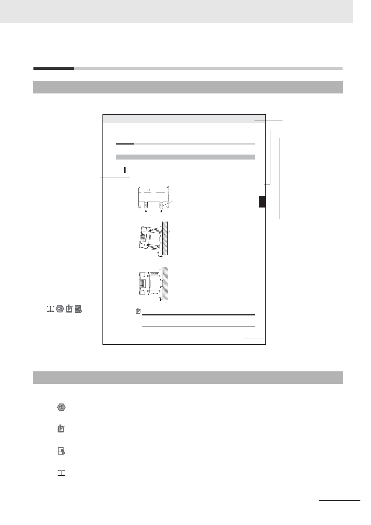
Page Structure and Icons
The following page structure and icons are used in this manual.
Level 2 heading
Level 3 heading
Step in a procedure
Indicates a step in a
procedure.
Special Information
(See below.)
Icons are used to indicate
precautions and
additional information.
5-2 Installation
5-2-1 Installation Location
DIN Track Installation
1
Use a screwdriver to pull down the DIN Track mounting pins from the back of the Units to release
them, and mount the Units to the DIN Track.
Fit the back of the Units onto the DIN Track by catching the top of the Units on the Track and then
2
pressing in at the bottom of the Units, as shown below.
Press in all of the DIN Track mounting pins to securely lock the Units in place.
3
DIN Track mounting pins
5 Installation and wiring
Level 1 heading
Level 2 heading
Level 3 heading
Gives the current
headings.
5-2 Installation
DIN Track mounting pins
Release
DIN Track
5
5-2-1 Installation Location
Page tab
Gives the number
of the section.
Manual name
This illustration is provided only as a sample and may not literally appear in this manual.
Special Information
Special information in this manual is classified as follows:
Precautions for Safe Use
Precautions on what to do and what not to do to ensure using the product safely.
Precautions for Correct Use
Precautions on what to do and what not to do to ensure proper operation and performance.
Additional Information
Additional information to increase understanding or make operation easier.
References to the location of more detailed or related information.
Precautions for Correct Use
Tighten terminal block screws and cable screws to the following torques.
M4: 1.2 N·m
M3: 0.5 N·m
CP1E CPU Unit Hardware User’s Manual(W479)
5 - 3
CP1E CPU Unit Instructions Reference Manual(W483)
5
Page 9

Terminology and Notation
Ter m Description
E-type CPU Unit A basic model of CPU Unit that support basic control applications using instructions such
as basic, movement, arithmetic, and comparison instructions.
Basic models of CPU Units are called “E-type CPU Units” in this manual.
N-type CPU Unit An application model of CPU Unit that supports connections to Programmable Terminals,
inverters, and servo drives.
Application models of CPU Units are called “N-type CPU Units” in this manual.
NA-type CPU Unit An application model of CPU Unit that supports built-in analog and connections to Pro-
grammable Terminals, inverters, and servo drives.
Application models of CPU Units with built-in analog are called “NA-type CPU Units” in
this manual.
CX-Programmer A programming device that applies for programming and debugging PLCs.
The CX-Programmer includes the Micro PLC Edition CX-Programmer (CX-One Lite), the
CX-Programmer (CX-One) and the CX-Programmer for CP1E.
This manual describes the unique applications and functions of the Micro PLC Edition
CX-Programmer version 9.03 or higher CX-Programmer for CP1E.
“CX-Programmer” refers to the Micro PLC Edition CX-Programmer version 9.03 or higher
CX-Programmer for CP1E in this manual.
Note E20/30/40 and N20/30/40 CPU Units are supported by CX-Programmer version 8.2
or higher. E10/14, N14/60 and NA20 CPU Units are supported by CX-Programmer
version 9.03 or higher.
6
CP1E CPU Unit Instructions Reference Manual(W483)
Page 10

Sections in this Manual
1
2
1
2
3
4
A
Summary of Instructions
Instructions
Instruction Execution Times and Number
of Steps
Monitoring and Computing the Cycle Time
Appendices
3
4
A
CP1E CPU Unit Instructions Reference Manual(W483)
7
Page 11

CONTENTS
Introduction ...............................................................................................................1
CP1E CPU Unit Manuals ...........................................................................................2
Manual Structure .......................................................................................................5
Safety Precautions .................................................................................................. 15
Precautions for Safe Use ........................................................................................18
Regulations and Standards....................................................................................19
Related Manuals ...................................................................................................... 20
Section 1 Summary of Instructions .............................................. 1-1
1-1 Summary of Instructions ........................................................................................................ 1-2
Section 2 Instructions .................................................................... 2-1
Notation and Layout of Instruction Descriptions ......................................................................... 2-2
Sequence Input Instructions .......................................................................................................... 2-5
LD/LD NOT ................................................................................................................................................ 2-7
AND/AND NOT .......................................................................................................................................... 2-9
OR/OR NOT .............................................................................................................................................2-11
AND LD/OR LD ........................................................................................................................................ 2-13
NOT .......................................................................................................................................................... 2-16
UP/DOWN ................................................................................................................................................ 2-17
Sequence Output Instructions ..................................................................................................... 2-18
OUT/OUT NOT ........................................................................................................................................ 2-18
TR ............................................................................................................................................................ 2-20
KEEP ....................................................................................................................................................... 2-21
DIFU ......................................................................................................................................................... 2-25
DIFD ......................................................................................................................................................... 2-27
SET/RSET ............................................................................................................................................... 2-29
SETA/RSTA .............................................................................................................................................. 2-31
SETB/RSTB .............................................................................................................................................2-33
Sequence Control Instructions..................................................................................................... 2-35
END ......................................................................................................................................................... 2-38
NOP ......................................................................................................................................................... 2-39
IL/ILC ....................................................................................................................................................... 2-40
MILH/MILR/MILC ..................................................................................................................................... 2-44
JMP/CJP/JME .......................................................................................................................................... 2-53
FOR/NEXT ............................................................................................................................................... 2-56
BREAK ..................................................................................................................................................... 2-59
Timer and Counter Instructions ................................................................................................... 2-60
TIM/TIMX ................................................................................................................................................. 2-66
TIMH/TIMHX ............................................................................................................................................ 2-69
TMHH/TMHHX ......................................................................................................................................... 2-72
TTIM/TTIMX .............................................................................................................................................2-74
TIML/TIMLX .............................................................................................................................................2-77
CNT/CNTX ............................................................................................................................................... 2-80
8
CP1E CPU Unit Instructions Reference Manual(W483)
Page 12

CNTR/CNTRX ......................................................................................................................................... 2-83
CNR/CNRX .............................................................................................................................................. 2-86
Comparison Instructions .............................................................................................................. 2-88
=, <>, <, <=, >, >= .................................................................................................................................... 2-88
=DT, <>DT, <DT, <=DT, >DT, >=DT ......................................................................................................... 2-91
CMP/CMPL .............................................................................................................................................. 2-95
CPS/CPSL ............................................................................................................................................... 2-98
TCMP .................................................................................................................................................... 2-101
BCMP .................................................................................................................................................... 2-103
ZCP/ZCPL ............................................................................................................................................. 2-105
Data Movement Instructions....................................................................................................... 2-108
MOV/MOVL/MVN ................................................................................................................................... 2-108
MOVB .................................................................................................................................................... 2-111
MOVD .................................................................................................................................................... 2-113
XFRB ..................................................................................................................................................... 2-115
XFER ..................................................................................................................................................... 2-117
BSET ..................................................................................................................................................... 2-119
XCHG .................................................................................................................................................... 2-121
DIST ...................................................................................................................................................... 2-123
COLL ..................................................................................................................................................... 2-125
Data Shift Instructions ................................................................................................................ 2-127
SFT ........................................................................................................................................................ 2-127
SFTR ..................................................................................................................................................... 2-129
WSFT .................................................................................................................................................... 2-131
ASL ........................................................................................................................................................ 2-133
ASR ....................................................................................................................................................... 2-134
ROL ....................................................................................................................................................... 2-135
ROR ....................................................................................................................................................... 2-137
SLD/SRD ............................................................................................................................................... 2-139
NASL/NSLL ........................................................................................................................................... 2-141
NASR/NSRL .......................................................................................................................................... 2-144
Increment/Decrement Instructions ............................................................................................ 2-147
++/++L ................................................................................................................................................... 2-147
--/--L ...................................................................................................................................................... 2-150
++B/++BL .............................................................................................................................................. 2-153
--B/--BL ................................................................................................................................................. 2-156
Symbol Math Instructions........................................................................................................... 2-158
+/+L ....................................................................................................................................................... 2-158
+C/+CL .................................................................................................................................................. 2-160
+B/+BL ................................................................................................................................................... 2-162
+BC/+BCL ............................................................................................................................................. 2-164
–/–L ........................................................................................................................................................ 2-166
–C/–CL .................................................................................................................................................. 2-170
–B/–BL ................................................................................................................................................... 2-172
–BC/–BCL .............................................................................................................................................. 2-175
*/*L ......................................................................................................................................................... 2-177
*B/*BL .................................................................................................................................................... 2-179
/, /L ......................................................................................................................................................... 2-181
/B, /BL .................................................................................................................................................... 2-183
Conversion Instructions.............................................................................................................. 2-185
BIN/BINL ................................................................................................................................................ 2-185
BCD/BCDL ............................................................................................................................................ 2-187
NEG ....................................................................................................................................................... 2-189
MLPX ..................................................................................................................................................... 2-191
DMPX .................................................................................................................................................... 2-196
ASC ....................................................................................................................................................... 2-201
HEX ....................................................................................................................................................... 2-205
Logic Instructions........................................................................................................................ 2-210
ANDW/ANDL ......................................................................................................................................... 2-210
ORW/ORWL .......................................................................................................................................... 2-212
CP1E CPU Unit Instructions Reference Manual(W483)
9
Page 13

XORW/XORL .........................................................................................................................................2-214
COM/COML ...........................................................................................................................................2-216
Special Math Instructions ........................................................................................................... 2-218
APR ........................................................................................................................................................2-218
BCNT .....................................................................................................................................................2-227
Floating-point Math Instructions ................................................................................................ 2-229
FIX/FIXL .................................................................................................................................................2-233
FLT/FLTL ................................................................................................................................................2-235
+F, –F, *F, /F ........................................................................................................................................... 2-237
=F, <>F, <F, <=F, >F, >=F ........................................................................................................................2-241
FSTR ......................................................................................................................................................2-244
FVAL ......................................................................................................................................................2-249
Table Data Processing Instructions ........................................................................................... 2-253
SWAP .....................................................................................................................................................2-253
FCS ........................................................................................................................................................2-255
Data Control Instructions............................................................................................................ 2-257
PIDAT .....................................................................................................................................................2-257
TPO ........................................................................................................................................................2-269
SCL ........................................................................................................................................................2-276
SCL2 ......................................................................................................................................................2-280
SCL3 ......................................................................................................................................................2-284
AVG ........................................................................................................................................................2-287
Subroutines Instructions ............................................................................................................ 2-290
SBS ........................................................................................................................................................2-290
SBN/RET ...............................................................................................................................................2-295
Interrupt Control Instructions..................................................................................................... 2-298
MSKS .....................................................................................................................................................2-300
CLI .........................................................................................................................................................2-303
DI ...........................................................................................................................................................2-306
EI ............................................................................................................................................................2-307
High-speed Counter/Pulse Output Instructions........................................................................ 2-308
INI ..........................................................................................................................................................2-308
PRV ........................................................................................................................................................2-311
CTBL ......................................................................................................................................................2-315
SPED .....................................................................................................................................................2-319
PULS ......................................................................................................................................................2-323
PLS2 ......................................................................................................................................................2-325
ACC ....................................................................................................................................................... 2-331
ORG .......................................................................................................................................................2-336
PWM ......................................................................................................................................................2-339
Step Instructions ......................................................................................................................... 2-341
SNXT/STEP ...........................................................................................................................................2-342
Basic I/O Unit Instructions.......................................................................................................... 2-352
IORF ......................................................................................................................................................2-352
SDEC .....................................................................................................................................................2-354
DSW .......................................................................................................................................................2-357
MTR .......................................................................................................................................................2-361
7SEG .....................................................................................................................................................2-365
Serial Communication Instructions ........................................................................................... 2-369
TXD ........................................................................................................................................................2-369
RXD .......................................................................................................................................................2-374
Clock Instructions........................................................................................................................ 2-380
CADD/CSUB ..........................................................................................................................................2-380
DATE ......................................................................................................................................................2-385
Failure Diagnosis Instructions ................................................................................................... 2-387
FAL .........................................................................................................................................................2-387
FALS ......................................................................................................................................................2-393
10
CP1E CPU Unit Instructions Reference Manual(W483)
Page 14

Other Instructions........................................................................................................................ 2-398
STC/CLC ............................................................................................................................................... 2-398
WDT ...................................................................................................................................................... 2-399
Section 3 Instruction Execution Times and Number of Steps ... 3-1
3-1 CP1E CPU Unit Instruction Execution Times and Number of Steps .................................. 3-2
Section 4 Monitoring and Computing the Cycle Time................. 4-1
4-1 Monitoring the Cycle Time...................................................................................................... 4-2
4-1-1 Monitoring the Cycle Time.......................................................................................................... 4-2
4-2 Computing the Cycle Time .....................................................................................................4-3
4-2-1 CPU Unit Operation Flowchart ................................................................................................... 4-3
4-2-2 Cycle Time Overview.................................................................................................................. 4-4
4-2-3 I/O Refresh Times for PLC Units ................................................................................................ 4-5
4-2-4 Cycle Time Calculation Example ................................................................................................ 4-6
4-2-5 Increase in Cycle Time for Online Editing................................................................................... 4-6
Section A Appendices ....................................................................A-1
Alphabetical List of Instructions by Mnemonic .............................................................................A-2
Revision History ....................................................................................... Revision-1
CP1E CPU Unit Instructions Reference Manual(W483)
11
Page 15

Read and Understand this Manual
Please read and understand this manual before using the product. Please consult your OMRON representative
if you have any questions or comments.
Warranty and Limitations of Liability
WARRANTY
OMRON’s exclusive warranty is that the products are free from defects in materials and workmanship for a
period of one year (or other period if specified) from date of sale by OMRON.
OMRON MAKES NO WARRANTY OR REPRESENTATION, EXPRESS OR IMPLIED, REGARDING NONINFRINGEMENT, MERCHANTABILITY, OR FITNESS FOR PARTICULAR PURPOSE OF THE
PRODUCTS. ANY BUYER OR USER ACKNOWLEDGES THAT THE BUYER OR USER ALONE HAS
DETERMINED THAT THE PRODUCTS WILL SUITABLY MEET THE REQUIREMENTS OF THEIR
INTENDED USE. OMRON DISCLAIMS ALL OTHER WARRANTIES, EXPRESS OR IMPLIED.
LIMITATIONS OF LIABILITY
OMRON SHALL NOT BE RESPONSIBLE FOR SPECIAL, INDIRECT, OR CONSEQUENTIAL DAMAGES,
LOSS OF PROFITS OR COMMERCIAL LOSS IN ANY WAY CONNECTED WITH THE PRODUCTS,
WHETHER SUCH CLAIM IS BASED ON CONTRACT, WARRANTY, NEGLIGENCE, OR STRICT
LIABILITY.
In no event shall the responsibility of OMRON for any act exceed the individual price of the product on which
liability is asserted.
IN NO EVENT SHALL OMRON BE RESPONSIBLE FOR WARRANTY, REPAIR, OR OTHER CLAIMS
REGARDING THE PRODUCTS UNLESS OMRON’S ANALYSIS CONFIRMS THAT THE PRODUCTS
WERE PROPERLY HANDLED, STORED, INSTALLED, AND MAINTAINED AND NOT SUBJECT TO
CONTAMINATION, ABUSE, MISUSE, OR INAPPROPRIATE MODIFICATION OR REPAIR.
12
CP1E CPU Unit Instructions Reference Manual(W483)
Page 16

Application Considerations
SUITABILITY FOR USE
OMRON shall not be responsible for conformity with any standards, codes, or regulations that apply to the
combination of products in the customer’s application or use of the products.
At the customer’s request, OMRON will provide applicable third party certification documents identifying
ratings and limitations of use that apply to the products. This information by itself is not sufficient for a
complete determination of the suitability of the products in combination with the end product, machine,
system, or other application or use.
The following are some examples of applications for which particular attention must be given. This is not
intended to be an exhaustive list of all possible uses of the products, nor is it intended to imply that the uses
listed may be suitable for the products:
• Outdoor use, uses involving potential chemical contamination or electrical interference, or conditions or
uses not described in this manual.
• Nuclear energy control systems, combustion systems, railroad systems, aviation systems, medical
equipment, amusement machines, vehicles, safety equipment, and installations subject to separate
industry or government regulations.
• Systems, machines, and equipment that could present a risk to life or property.
Please know and observe all prohibitions of use applicable to the products.
NEVER USE THE PRODUCTS FOR AN APPLICATION INVOLVING SERIOUS RISK TO LIFE OR
PROPERTY WITHOUT ENSURING THAT THE SYSTEM AS A WHOLE HAS BEEN DESIGNED TO
ADDRESS THE RISKS, AND THAT THE OMRON PRODUCTS ARE PROPERLY RATED AND INSTALLED
FOR THE INTENDED USE WITHIN THE OVERALL EQUIPMENT OR SYSTEM.
PROGRAMMABLE PRODUCTS
OMRON shall not be responsible for the user’s programming of a programmable product, or any
consequence thereof.
CP1E CPU Unit Instructions Reference Manual(W483)
13
Page 17

Disclaimers
CHANGE IN SPECIFICATIONS
Product specifications and accessories may be changed at any time based on improvements and other
reasons.
It is our practice to change model numbers when published ratings or features are changed, or when
significant construction changes are made. However, some specifications of the products may be changed
without any notice. When in doubt, special model numbers may be assigned to fix or establish key
specifications for your application on your request. Please consult with your OMRON representative at any
time to confirm actual specifications of purchased products.
DIMENSIONS AND WEIGHTS
Dimensions and weights are nominal and are not to be used for manufacturing purposes, even when
tolerances are shown.
PERFORMANCE DATA
Performance data given in this manual is provided as a guide for the user in determining suitability and does
not constitute a warranty. It may represent the result of OMRON’s test conditions, and the users must
correlate it to actual application requirements. Actual performance is subject to the OMRON Warranty and
Limitations of Liability.
ERRORS AND OMISSIONS
The information in this manual has been carefully checked and is believed to be accurate; however, no
responsibility is assumed for clerical, typographical, or proofreading errors, or omissions.
14
CP1E CPU Unit Instructions Reference Manual(W483)
Page 18
Safety Precautions
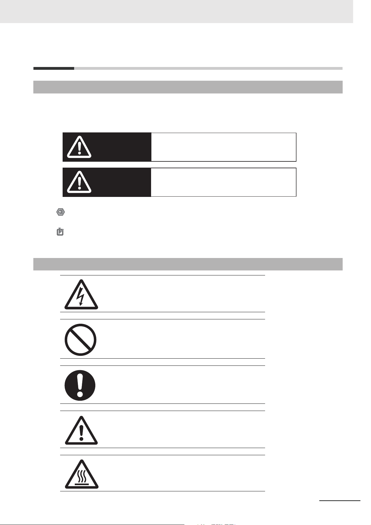
Definition of Precautionary Information
The following notation is used in this manual to provide precautions required to ensure safe usage of a
CP-series PLC. The safety precautions that are provided are extremely important to safety. Always read
and heed the information provided in all safety precautions.
Indicates an imminently hazardous situation which,
WARNING
Caution
Precautions for Safe Use
Indicates precautions on what to do and what not to do to ensure using the product safely.
Precautions for Correct Use
Indicates precautions on what to do and what not to do to ensure proper operation
and performance.
if not avoided, will result in death or serious injury.
Additionally, there may be severe property damage.
Indicates a potentially hazardous situation which,
if not avoided, may result in minor or moderate
injury, or property damage.
Symbols
The triangle symbol indicates precautions (including
warnings). The specific operation is shown in the triangle
and explained in text. This example indicates a precaution for electric shock.
The circle and slash symbol indicates operations that you
must not do. The specific operation is shown in the circle
and explained in text.
The filled circle symbol indicates operations that you
must do. The specific operation is shown in the circle and
explained in text. This example shows a general precaution for something that you must do.
The triangle symbol indicates precautions (including
warnings). The specific operation is shown in the triangle
and explained in text. This example indicates a general
precaution.
The triangle symbol indicates precautions (including
warnings). The specific operation is shown in the triangle
and explained in text. This example indicates a precaution for hot surfaces.
CP1E CPU Unit Instructions Reference Manual(W483)
15
Page 19

CautionCaution
Be sure to sufficiently confirm the safety at the destination when you transfer
the program or I/O memory or perform procedures to change the I/O memory.
Devices connected to PLC outputs may incorrectly operate regardless of the operating mode of the CPU Unit.
With an E-type CPU Unit or with an N/NA-type CPU Unit without a Battery, the contents of the DM Area (D) *, Holding Area (H), the Counter Present Values (C), the status of Counter Completion Flags (C), and the status of bits in the Auxiliary Area (A)
related to clock functions may be unstable when the power supply is turned ON.
*This does not apply to areas backed up to EEPROM using the DM backup function.
If the DM backup function is being used, be sure to use one of the following methods
for initialization.
1. Clearing All Areas to All Zeros
Select the Clear Held Memory (HR/DM/CNT) to Zero Check Box in the Startup
Data Read Area in the PLC Setup.
2. Clearing Specific Areas to All Zeros or Initializing to Specific Values
Make the settings from a ladder program.
If the data is not initialized, the unit or device may operate unexpectedly because of
unstable data.
Execute online edit only after confirming that no adverse effects will be caused
by extending the cycle time.
Otherwise, the input signals may not be readable.
The DM Area (D), Holding Area (H), Counter Completion Flags (C), and Counter
Present Values (C) will be held by the Battery if a Battery is mounted in a CP1EN/NAD- CPU Unit. When the battery voltage is low, however, I/O memory
areas that are held (including the DM, Holding, and Counter Areas) will be unstable.
The unit or device may operate unexpectedly because of unstable data.
Use the Battery Error Flag or other measures to stop outputs if external outputs are performed from a ladder program based on the contents of the DM
Area or other I/O memory areas.
Sufficiently check safety if I/O bit status or present values are monitored in the
Ladder Section Pane or present values are monitored in the Watch Pane.
If bits are set, reset, force-set, or force-reset by inadvertently pressing a shortcut key,
devices connected to PLC outputs may operate incorrectly regardless of the operating mode.
16
CP1E CPU Unit Instructions Reference Manual(W483)
Page 20

Caution
Program so that the memory area of the start address is not exceeded when
using a word address or symbol for the offset.
For example, write the program so that processing is executed only when the indirect
specification does not cause the final address to exceed the memory area by using
an input comparison instruction or other instruction.
If an indirect specification causes the address to exceed the area of the start address,
the system will access data in other area, and unexpected operation may occur.
Set the temperature range according to the type of temperature sensor connected to the Unit.
Temperature data will not be converted correctly if the temperature range does not
match the sensor.
Do not set the temperature range to any values other than those for which temperature ranges are given in the following table.
An incorrect setting may cause operating errors.
CP1E CPU Unit Instructions Reference Manual(W483)
17
Page 21

Precautions for Safe Use
Observe the following precautions when using a CP-series PLC.
Handling
• To initialize the DM Area, back up the initial contents for the DM Area to backup memory using
one of the following methods.
• Set the number of words of the DM Area to be backed up starting with D0 in the Number of
CH of DM for backup Box in the Startup Data Read Area.
• Include programming to back up specified words in the DM Area to built-in EEPROM by turning ON A751.15 (DM Backup Save Start Bit).
• Check the ladder program for proper execution before actually running it on the Unit. Not checking
the program may result in an unexpected operation.
• The ladder program and parameter area data in the CP1E CPU Units are backed up in the built-in
EEPROM backup memory. The BKUP indicator will light on the front of the CPU Unit when the
backup operation is in progress. Do not turn OFF the power supply to the CPU Unit when the
BKUP indicator is lit. The data will not be backed up if power is turned OFF and a memory error
will occur the next time the power supply is turned ON.
• With a CP1E CPU Unit, data memory can be backed up to the built-in EEPROM backup memory.
The BKUP indicator will light on the front of the CPU Unit when backup is in progress. Do not turn
OFF the power supply to the CPU Unit when the BKUP indicator is lit. If the power is turned OFF
during a backup, the data will not be backed up and will not be transferred to the DM Area in RAM
the next time the power supply is turned ON.
• Before replacing the battery, supply power to the CPU Unit for at least 30 minutes and then complete battery replacement within 5 minutes. Memory data may be corrupted if this precaution is
not observed.
• The equipment may operate unexpectedly if inappropriate parameters are set. Even if the appropriate parameters are set, confirm that equipment will not be adversely affected before transferring the parameters to the CPU Unit.
• Before starting operation, confirm that the contents of the DM Area is correct.
• After replacing the CPU Unit, make sure that the required data for the DM Area, Holding Area, and
other memory areas has been transferred to the new CPU Unit before restarting operation.
• Do not attempt to disassemble, repair, or modify any Units. Any attempt to do so may result in malfunction, fire, or electric shock.
• Confirm that no adverse effect will occur in the system before attempting any of the following. Not
doing so may result in an unexpected operation.
• Changing the operating mode of the PLC (including the setting of the startup operating mode).
• Force-setting/force-resetting any bit in memory.
• Changing the present value of any word or any set value in memory.
18
External Circuits
• Always configure the external circuits to turn ON power to the PLC before turning ON power to the
control system. If the PLC power supply is turned ON after the control power supply, temporary
errors may result in control system signals because the output terminals on DC Output Units and
other Units will momentarily turn ON when power is turned ON to the PLC.
• Fail-safe measures must be taken by the customer to ensure safety in the event that outputs from
output terminals remain ON as a result of internal circuit failures, which can occur in relays, transistors, and other elements.
• If the I/O Hold Bit is turned ON, the outputs from the PLC will not be turned OFF and will maintain
their previous status when the PLC is switched from RUN or MONITOR mode to PROGRAM mode.
Make sure that the external loads will not produce dangerous conditions when this occurs. (When
operation stops for a fatal error, including those produced with the FALS instruction, all outputs from
PLC will be turned OFF and only the internal output status in the CPU Unit will be maintained.)
CP1E CPU Unit Instructions Reference Manual(W483)
Page 22

Regulations and Standards
Trademarks
SYSMAC is a registered trademark for Programmable Controllers made by OMRON Corporation.
CX-One is a registered trademark for Programming Software made by OMRON Corporation.
Windows is a registered trademark of Microsoft Corporation.
Other system names and product names in this document are the trademarks or registered trademarks
of their respective companies.
CP1E CPU Unit Instructions Reference Manual(W483)
19
Page 23

Related Manuals
The following manuals are related to the CP1E. Use them together with this manual.
Manual name Cat. No. Model numbers Application Contents
SYSMAC CP Series
CP1E CPU Unit Instructions Reference Manual
(this manual)
SYSMAC CP Series
CP1E CPU Unit Software User’s Manual
SYSMAC CP Series
CP1E CPU Unit Hardware User’s Manual
CS/CJ/CP/NSJ Series
Communications Commands Reference Manual
SYSMAC CP Series
CP1L/CP1E CPU Unit
Introduction Manual
W483 CP1E-ED-
W480 CP1E-ED-
W479 CP1E-ED-
W342 CS1G/H-CPUH
W461
CP1E-ND-
CP1E-NAD-
CP1E-ND-
CP1E-NAD-
CP1E-ND-
CP1E-NAD-
CS1G/H-CPU-V1
CS1D-CPUH
CS1D-CPUS
CS1W-SCU
1W-SCB-V1
CS
CJ1G/H-CPUH
CJ1G-CPUP
CJ1M-CPU
CJ1G-CPU
CJ1W-SCU-V1
CP1L-L10D-
CP1L-L14D-
CP1L-L20D-
CP1L-M30D-
CP1L-M40D-
CP1L-M60D-
CP1E-ED-
CP1E-ND-
CP1E-NAD-
-V1
To learn programming instructions in
detail
To learn the software
specifications of the
CP1E PLCs
Use this manual together with the CP1E CPU Unit Hardware User’s
Manual (Cat. No. W479) and Instructions Reference Manual (Cat. No.
W483).
To learn the hardware specifications
of the CP1E PLCs
Use this manual together with the CP1E CPU Unit Software User’s
Manual (Cat. No. W480) and Instructions Reference Manual (Cat. No.
W483).
To learn communications commands for
CS/CJ/CP/NSJseries Controllers in
detail
Note This manual describes commands addressed to CPU Units. It
does not cover commands addressed to other Units or ports (e.g.,
serial communications ports on CPU Units, communications ports
on Serial Communications Units/Boards, and other Communications Units).
To learn the basic
setup methods of the
CP1L/CP1E PLCs
Describes each programming instruction in
detail.
When programming, use this manual together
with the CP1E CPU Unit Software User’s Manual (Cat. No. W480).
Describes the following information for CP1E
PLCs.
• CPU Unit operation
• Internal memory
• Programming
• Settings
• CPU Unit built-in functions
• Interrupts
• High-speed counter inputs
• Pulse outputs
• Serial communications
• Other functions
Describes the following information for CP1E
PLCs.
• Overview and features
• Basic system configuration
• Part names and functions
• Installation and settings
• Troubleshooting
Describes
1) C-mode commands and
2) FINS commands in detail.
Read this manual for details on C-mode and
FINS commands addressed to CPU Units.
Describes the following information for
CP1L/CP1E PLCs.
• Basic configuration and component names
• Mounting and wiring
• Programming, data transfer, and debugging
using the CX-Programmer
• Application program examples
20
CP1E CPU Unit Instructions Reference Manual(W483)
Page 24

Page 25

Summary of Instructions
This section provides a summary of instructions used with a CP1E CPU Unit.
1-1 Summary of Instructions . . . . . . . . . . . . . . . . . . . . . . . . . . . . . . . . . . . . . . . . 1-2
1
CP1E CPU Unit Instructions Reference Manual(W483)
1-1
Page 26

1 Summary of Instructions
1-1 Summary of Instructions
There are 200 types of instructions can be used by CP1E.
The following table lists the instructions by function. Refer to the reference pages for the
detail of each instruction.
Instrucion
Typ e
Sequence
Input Instructions
Instruction Mnemonic
LOAD LD
@LD
%LD
!LD
!@LD
!%LD
LOAD NOT LD NOT
@LD NOT
%LD NOT
!LD NOT
!@LD NOT
!%LD NOT
AND AND
@AND
%AND
!AND
!@AND
!%AND
AND NOT AND NOT
@AND NOT
%AND NOT
!AND NOT
!@AND NOT
!%AND NOT
OR OR
@OR
%OR
!OR
!@OR
!%OR
OR NOT OR NOT
@OR NOT
%OR NOT
!OR NOT
!@OR NOT
!%OR NOT
AND LOAD AND LD
OR LOAD OR LD
NOT NOT 520 Reverses the execution condition. 2-16
CONDITION ON UP 521 UP(521) turns ON the execution condition for one cycle when the execution
CONDITION OFF DOWN 522 DOWN(522) turns ON the execution condition for one cycle when the execution
FUN
No.
-
Indicates a logical start and creates an ON/OFF execution condition based on
the ON/OFF status of the specified operand bit.
-
-
-
-
-
-
Indicates a logical start and creates an ON/OFF execution condition based on
the reverse of the ON/OFF status of the specified operand bit.
-
-
-
-
-
-
Takes a logical AND of the status of the specified operand bit and the current
execution condition.
-
-
-
-
-
-
Reverses the status of the specified operand bit and takes a logical AND with
the current execution condition.
-
-
-
-
-
-
Takes a logical OR of the ON/OFF status of the specified operand bit and the
current execution condition.
-
-
-
-
-
-
Reverses the status of the specified bit and takes a logical OR with the current
execution condition.
-
-
-
-
-
-
Takes a logical AND between logic blocks. 2-13
-
Takes a logical OR between logic blocks. 2-13
condition goes from OFF to ON.
condition goes from ON to OFF.
Function Page
2-7
2-7
2-9
2-9
2-11
2-11
2-17
2-17
1-2
CP1E CPU Unit Instructions Reference Manual(W483)
Page 27

1 Summary of Instructions
1-1 Summary of Instructions
Instrucion
Type
Sequence
Output
Instructions
Instruction Mnemonic
OUTPUT OUT
!OUT
OUTPUT NOT OUT NOT
!OUT NOT
TR Bits TR
KEEP KEEP 011 Operates as a latching relay. 2-21
!KEEP
DIFFERENTIATEUPDIFU 013 DIFU(013) turns the designated bit ON for one cycle when the execution condi-
!DIFU
DIFFERENTIATE
DOWN
SET SET
RESET RSET
MULTIPLE BIT SET SETA 530 SETA(530) turns ON the specified number of consecutive bits. 2-31
MULTIPLE BIT
RESET
SINGLE BIT SET SETB 532 SETB(532) turns ON the specified bit in the specified word when the execution
SINGLE BIT RESET RSTB 533 RSTB(533) turns OFF the specified bit in the specified word when the execu-
DIFD 014 DIFD(014) turns the designated bit ON for one cycle when the execution condi-
!DIFD
@SET
%SET
!SET
!@SET
!%SET
@RSET
%RSET
!RSET
!@RSET
!%RSET
@SETA
RSTA 531 RSTA(531) turns OFF the specified number of consecutive bits. 2-31
@RSTA
@SETB
!SETB
!@SETB
@RSTB
!RSTB
!@RSTB
FUN
No.
-
Outputs the result (execution condition) of the logical processing to the specified bit.
-
-
Reverses the result (execution condition) of the logical processing, and outputs
it to the specified bit.
-
-
TR bits are used to temporarily retain the ON/OFF status of execution conditions in a program when programming in mnemonic code.
tion goes from OFF to ON (rising edge).
tion goes from ON to OFF (falling edge).
-
SET turns the operand bit ON when the execution condition is ON. 2-29
-
-
-
-
-
-
RSET turns the operand bit OFF when the execution condition is ON. 2-29
-
-
-
-
-
condition is ON.
Unlike the SET instruction, SETB(532) can be used to set a bit in a DM word.
tion condition is ON.
Unlike the RSET instruction, RSTB(533) can be used to reset a bit in a DM
word.
Function Page
2-18
2-18
2-20
2-25
2-27
2-33
2-33
1
CP1E CPU Unit Instructions Reference Manual(W483)
1-3
Page 28

1 Summary of Instructions
Instrucion
Typ e
Sequence
Control
Instructions
Timer and
Counter
Instructions
Instruction Mnemonic
END END 001 Indicates the end of a program. 2-38
NO OPERATION NOP 000 This instruction has no function. (No processing is performed for NOP(000).) 2-39
INTERLOCK IL 002 Interlocks all outputs between IL(002) and ILC(003) when the execution condi-
INTERLOCK
CLEAR
MULTI-INTERLOCK
DIFFERENTIATION
HOLD
MULTI-INTERLOCK
DIFFERENTIATION
RELEASE
MULTI-INTERLOCK
CLEAR
JUMP JMP 004 When the execution condition for JMP(004) is OFF, program execution jumps
JUMP END JME 005 Indicates the end of a jump initiated by JMP(004) or CJP(510). 2-53
CONDITIONAL
JUMP
FOR LOOP FOR 512 The instructions between FOR(512) and NEXT(513) are repeated a specified
NEXT LOOP NEXT 513 The instructions between FOR(512) and NEXT(513) are repeated a specified
BREAK LOOP BREAK 514 Programmed in a FOR-NEXT loop to cancel the execution of the loop for a
HUNDRED-MS
TIMER
TEN-MS TIMER TIMH 015 TIMH(015)/TIMHX(551) operates a decrementing timer with units of 10-ms. 2-69
ONE-MS TIMER TMHH 540 TMHH(540)/TMHHX(552) operates a decrementing timer with units of 1-ms. 2-72
ACCUMULATIVE
TIMER
LONG TIMER TIML 542 TIML(542)/TIMLX(553) operates a decrementing timer with units of 0.1-s. 2-77
COUNTER CNT
REVERSIBLE
COUNTER
RESET TIMER/
COUNTER
ILC 003 All outputs between IL(002) and ILC(003) are interlocked when the execution
MILH 517 When the execution condition for MILH(517) is OFF, the outputs for all instruc-
MILR 518 When the execution condition for MILR(518) is OFF, the outputs for all instruc-
MILC 519 Clears an interlock started by an MILH(517) or MILR(518) with the same inter-
CJP 510 The operation of CJP(510) is the basically the opposite of JMP(004). When the
TIM
TIMX 550
TIMHX 551
TMHHX 552
TTIM 087 TTIM(087)/TTIMX(555) operates an incrementing timer with units of 0.1-s. 2-74
TTIMX 555
TIMLX 553
CNTX 546
CNTR 012 CNTR(012)/CNTRX(548) operates a reversible counter. 2-83
CNTRX 548
CNR/
@CNR
CNRX/
@CNRX
FUN
No.
tion for IL(002) is OFF.
condition for IL(002) is OFF.
tions between that MILH(517) instruction and the next MILC(519) instruction
are interlocked.
tions between that MILR(518) instruction and the next MILC(519) instruction
are interlocked.
lock number.
directly to the first JME(005) in the program with the same jump number.
execution condition for CJP(510) is ON, program execution jumps directly to the
first JME(005) in the program with the same jump number.
number of times.
number of times.
given execution condition. The remaining instructions in the loop are processed
as NOP(000) instructions.
-
TIM/TIMX(550) operates a decrementing timer with units of 0.1-s. 2-66
-
CNT/CNTX(546) operates a decrementing counter. 2-80
545 CNR(545)/CNRX(547) resets the timers or counters within the specified range
of timer or counter numbers.
547
Function Page
2-40
2-40
2-44
2-44
2-44
2-53
2-53
2-56
2-56
2-59
2-86
1-4
CP1E CPU Unit Instructions Reference Manual(W483)
Page 29

1 Summary of Instructions
1-1 Summary of Instructions
Instrucion
Type
Comparison
Instructions
Data Movement Instructions
Instruction Mnemonic
Symbol Comparison = , <> , < , <= ,
Time Comparison LD, AND,
UNSIGNED
COMPARE
DOUBLE
UNSIGNED
COMPARE
SIGNED BINARY
COMPARE
DOUBLE SIGNED
BINARY COMPARE
TABLE COMPARE TCMP 085 Compares the source data to the contents of 16 words and turns ON the corre-
UNSIGNED BLOCK
COMPARE
AREA RANGE
COMPARE
DOUBLE AREA
RANGE COMPARE
MOVE MOV 021 Transfers a word of data to the specified word. 2-108
DOUBLE MOVE MOVL/
MOVE NOT MVN/
MOVE BIT MOVB/
MOVE DIGIT MOVD/
MULTIPLE BIT
TRANSFER
BLOCK TRANSFER XFER/
BLOCK SET BSET/
DATA EXCHANGE XCHG/
SINGLE WORD
DISTRIBUTE
DATA COLLECT COLL/
> , >=
OR+=DT
LD, AND,
OR+<>DT
LD, AND,
OR+<DT
LD, AND,
OR+<=DT
LD, AND,
OR+>DT
LD, AND,
OR+>=DT
CMP 020 Compares two unsigned binary values (constants and/or the contents of speci-
!CMP
CMPL 060 Compares two double unsigned binary values (constants and/or the contents of
CPS 114 Compares two signed binary values (constants and/or the contents of specified
!CPS
CPSL 115 Compares two double signed binary values (constants and/or the contents of
@TCMP
BCMP 068 Compares the source data to 16 ranges (defined by 16 lower limits and 16
@BCMP
ZCP 088 Compares the 16-bit unsigned binary value in CD (word contents or constant)
ZCPL 116 Compares the 32-bit unsigned binary value in CD and CD+1 (word contents or
@MOV
!MOV
!@MOV
@MOVL
@MVN
@MOVB
@MOVD
XFRB/
@XFRB
@XFER
@BSET
@XCHG
DIST/
@DIST
@COLL
FUN
No.
300
Symbol comparison instructions compare two values and create an ON execu-
∼
tion condition when the comparison condition is true.
328
341 Time comparison instructions compare two BCD time values and create an ON
execution condition when the comparison condition is true.
342
343
344
345
346
fied words) and outputs the result to the Arithmetic Flags in the Auxiliary Area.
specified words) and outputs the result to the Arithmetic Flags in the Auxiliary
Area.
words) and outputs the result to the Arithmetic Flags in the Auxiliary Area.
specified words) and outputs the result to the Arithmetic Flags in the Auxiliary
Area.
sponding bit in the result word when the contents are equal.
upper limits) and turns ON the corresponding bit in the result word when the
source data is within the range.
to the range defined by LL and UL and outputs the results to the Arithmetic
Flags in the Auxiliary Area.
constant) to the range defined by LL and UL and outputs the results to the
Arithmetic Flags in the Auxiliary Area.
498 Transfers two words of data to the specified words. 2-108
022 Transfers the complement of a word of data to the specified word. 2-108
082 Transfers the specified bit. 2-111
083 Transfers the specified digit or digits. (Each digit is made up of 4 bits.) 2-113
Transfers the specified number of consecutive bits. 2-115
062
070 Transfers the specified number of consecutive words. 2-117
071 Copies the same word to a range of consecutive words. 2-119
073 Exchanges the contents of the two specified words. 2-121
080 Transfers the source word to a destination word calculated by adding an offset
value to the base address.
081 Transfers the source word (calculated by adding an offset value to the base
address) to the destination word.
Function Page
2-88
2-91
2-95
2-95
2-98
2-98
2-101
2-103
2-105
2-105
2-123
2-125
1
CP1E CPU Unit Instructions Reference Manual(W483)
1-5
Page 30

1 Summary of Instructions
Instrucion
Typ e
Data Shift
Instructions
Increment/
Decrement
Instructions
Instruction Mnemonic
SHIFT REGISTER SFT 010 Operates a shift register. 2-127
REVERSIBLE
SHIFT REGISTER
WORD SHIFT WSFT/
ARITHMETIC
SHIFT LEFT
ARITHMETIC
SHIFT RIGHT
ROTATE LEFT ROL/
ROTATE RIGHT ROR/
ONE DIGIT SHIFT
LEFT
ONE DIGIT SHIFT
RIGHT
SHIFT N-BITS LEFT NASL/
DOUBLE SHIFT
N-BITS LEFT
SHIFT N-BITS
RIGHT
DOUBLE SHIFT
N-BITS RIGHT
INCREMENT
BINARY
DOUBLE INCREMENT BINARY
DECREMENT
BINARY
DOUBLE DECREMENT BINARY
INCREMENT BCD ++B/
DOUBLE INCREMENT BCD
DECREMENT BCD
DOUBLE DECREMENT BCD
SFTR/
@SFTR
@WSFT
ASL/
@ASL
ASR/
@ASR
@ROL
@ROR
SLD/
@SLD
SRD/
@SRD
@NASL
NSLL/
@NSLL
NASR/
@NASR
NSRL/
@NSRL
++/
@++
++L/
@++L
--
/
@
--
--
L/
@
--
L
@++B
++BL/
@++BL
--
B/
@
--
B
--
BL/
@
--
BL
FUN
No.
084 Creates a shift register that shifts data to either the right or the left. 2-129
016 Shifts data between St and E in word units. 2-131
025
Shifts the contents of Wd one bit to the left.
026 Shifts the contents of Wd one bit to the right. 2-134
027 Shifts all Wd bits one bit to the left including the Carry Flag (CY). 2-135
028 Shifts all Wd bits one bit to the right including the Carry Flag (CY). 2-137
074 Shifts data by one digit (4 bits) to the left. 2-139
075 Shifts data by one digit (4 bits) to the right. 2-139
580 Shifts the specified 16 bits of word data to the left by the specified number of
bits.
582 Shifts the specified 32 bits of word data to the left by the specified number of
bits.
581 Shifts the specified 16 bits of word data to the right by the specified number of
bits.
583 Shifts the specified 32 bits of word data to the right by the specified number of
bits.
590 Increments the 4-digit hexadecimal content of the specified word by 1. 2-147
591 Increments the 8-digit hexadecimal content of the specified words by 1. 2-147
592 Decrements the 4-digit hexadecimal content of the specified word by 1. 2-150
593 Decrements the 8-digit hexadecimal content of the specified words by 1. 2-150
594 Increments the 4-digit BCD content of the specified word by 1. 2-153
595 Increments the 8-digit BCD content of the specified words by 1. 2-153
596 Decrements the 4-digit BCD content of the specified word by 1. 2-156
597 Decrements the 8-digit BCD content of the specified words by 1. 2-156
Function Page
2-133
2-141
2-141
2-144
2-144
1-6
CP1E CPU Unit Instructions Reference Manual(W483)
Page 31

1 Summary of Instructions
1-1 Summary of Instructions
Instrucion
Type
Symbol Math
Instructions
Instruction Mnemonic
SIGNED BINARY
ADD WITHOUT
CARRY
DOUBLE SIGNED
BINARY ADD
WITHOUT CARRY
SIGNED BINARY
ADD WITH CARRY
DOUBLE SIGNED
BINARY ADD WITH
CARRY
BCD ADD
WITHOUT CARRY
DOUBLE BCD ADD
WITHOUT CARRY
BCD ADD WITH
CARRY
DOUBLE BCD ADD
WITH CARRY
SIGNED BINARY
SUBTRACT
WITHOUT CARRY
DOUBLE SIGNED
BINARY
SUBTRACT WITHOUT CARRY
SIGNED BINARY
SUBTRACT WITH
CARRY
DOUBLE SIGNED
BINARY WITH
CARRY
BCD SUBTRACT
WITHOUT CARRY
DOUBLE BCD
SUBTRACT
WITHOUT CARRY
BCD SUBTRACT
WITH CARRY
DOUBLE BCD
SUBTRACT
WITH CARRY
SIGNED BINARY
MULTIPLY
DOUBLE SIGNED
BINARY MULTIPLY
BCD MULTIPLY ∗B/
DOUBLE BCD
MULTIPLY
SIGNED BINARY
DIVIDE
DOUBLE SIGNED
BINARY DIVIDE
BCD DIVIDE /B
DOUBLE BCD
DIVIDE
+/
@+
+L/
@+L
+C/
@+C
+CL/
@+CL
+B/
@+B
+BL/
@+BL
+BC/
@+BC
+BCL/
@+BCL
@
@
@
@
@
@
@
@
∗/
@∗
∗L/
@∗L
@∗B
∗BL/
@∗BL
/
@/
/L
@/L
@/B
/BL
@/BL
/
-
L/
-
L
C/
-
C
CL/
-
CL
B/
-
B
BL/
-
BL
BC/
-
BC
BCL/
-
BCL
FUN
No.
400 Adds 4-digit (single-word) hexadecimal data and/or constants. 2-158
401 Adds 8-digit (double-word) hexadecimal data and/or constants. 2-158
402 Adds 4-digit (single-word) hexadecimal data and/or constants with the Carry
Flag (CY).
403 Adds 8-digit (double-word) hexadecimal data and/or constants with the Carry
Flag (CY).
404 Adds 4-digit (single-word) BCD data and/or constants. 2-162
405 Adds 8-digit (double-word) BCD data and/or constants. 2-162
406 Adds 4-digit (single-word) BCD data and/or constants with the Carry Flag (CY). 2-164
407 Adds 8-digit (double-word) BCD data and/or constants with the Carry Flag (CY). 2-164
410 Subtracts 4-digit (single-word) hexadecimal data and/or constants. 2-166
411 Subtracts 8-digit (double-word) hexadecimal data and/or constants. 2-166
412 Subtracts 4-digit (single-word) hexadecimal data and/or constants with the
Carry Flag (CY).
413 Subtracts 8-digit (double-word) hexadecimal data and/or constants with the
Carry Flag (CY).
414 Subtracts 4-digit (single-word) BCD data and/or constants. 2-172
415 Subtracts 8-digit (double-word) BCD data and/or constants. 2-172
416 Subtracts 4-digit (single-word) BCD data and/or constants with the Carry Flag
(CY).
417 Subtracts 8-digit (double-word) BCD data and/or constants with the Carry Flag
(CY).
420 Multiplies 4-digit signed hexadecimal data and/or constants. 2-177
421 Multiplies 8-digit signed hexadecimal data and/or constants. 2-177
424 Multiplies 4-digit (single-word) BCD data and/or constants. 2-179
425 Multiplies 8-digit (double-word) BCD data and/or constants. 2-179
430 Divides 4-digit (single-word) signed hexadecimal data and/or constants. 2-181
431 Divides 8-digit (double-word) signed hexadecimal data and/or constants. 2-181
434 Divides 4-digit (single-word) BCD data and/or constants. 2-183
435 Divides 8-digit (double-word) BCD data and/or constants. 2-183
Function Page
2-160
2-160
2-170
2-170
2-175
2-175
1
CP1E CPU Unit Instructions Reference Manual(W483)
1-7
Page 32

1 Summary of Instructions
Instrucion
Typ e
Conversion
Instructions
Logic Instructions
Special Math
Instructions
Instruction Mnemonic
BCD TO BINARY BIN/
DOUBLE BCD TO
DOUBLE BINARY
BINARY TO BCD BCD/
DOUBLE BINARY
TO DOUBLE BCD
2’S COMPLEMENT NEG/
DATA DECODER MLPX/
DATA ENCOD ER DM PX/
ASCII CONVERT ASC/
ASCII TO HEX HEX/
LOGICAL AND ANDW/
DOUBLE LOGICAL
AND
LOGICAL OR ORW/
DOUBLE LOGICAL ORORWL/
EXCLUSIVE OR XORW/
DOUBLE EXCLUSIVE OR
COMPLEMENT COM/
DOUBLE
COMPLEMENT
ARITHMETIC PROCESS
BIT COUNTER BCNT/
@BIN
BINL/
@BINL
@BCD
BCDL/
@BCDL
@NEG
@MLPX
@DMPX
@ASC
@HEX
@ANDW
ANDL/
@ANDL
@ORW
@ORWL
@XORW
XORL/
@XORL
@COM
COML/
@COML
APR/
@APR
@BCNT
FUN
No.
023 Converts BCD data to binary data. 2-185
058 Converts 8-digit BCD data to 8-digit hexadecimal (32-bit binary) data. 2-185
024 Converts a word of binary data to a word of BCD data. 2-187
059 Converts 8-digit hexadecimal (32-bit binary) data to 8-digit BCD data. 2-187
160 Calculates the 2' complement of a word of hexadecimal data. 2-189
076 Reads the numerical value in the specified digit (or byte) in the source word,
turns ON the corresponding bit in the result word (or 16-word range), and turns
OFF all other bits in the result word (or 16-word range).
077 FInds the location of the first or last ON bit within the source word (or 16-word
range), and writes that value to the specified digit (or byte) in the result word.
086 Converts 4-bit hexadecimal digits in the source word into their 8-bit ASCII
equivalents.
162 Converts up to 4 bytes of ASCII data in the source word to their hexadecimal
equivalents and writes these digits in the specified destination word.
034 Takes the logical AND of corresponding bits in single words of word data and/or
constants.
610 Takes the logical AND of corresponding bits in double words of word data
and/or constants.
035 Takes the logical OR of corresponding bits in single words of word data and/or
constants.
611 Takes the logical OR of corresponding bits in double words of word data and/or
constants.
036 Takes the logical exclusive OR of corresponding bits in single words of word
data and/or constants.
612 Takes the logical exclusive OR of corresponding bits in double words of word
data and/or constants.
029 Turns OFF all ON bits and turns ON all OFF bits in Wd. 2-216
614 Turns OFF all ON bits and turns ON all OFF bits in Wd and Wd+1. 2-216
069 Calculates the sine, cosine, or a linear extrapolation of the source data. 2-218
067 Counts the total number of ON bits in the specified word(s). 2-227
Function Page
2-191
2-196
2-201
2-205
2-210
2-210
2-212
2-212
2-214
2-214
1-8
CP1E CPU Unit Instructions Reference Manual(W483)
Page 33

1 Summary of Instructions
1-1 Summary of Instructions
Instrucion
Type
Floating-point
Math Instructions
Tabl e D at a
Processing
Instructions
Data Control
Instructions
Subroutine
Instructions
Interrupt
Control
Instructions
Instruction Mnemonic
FLOATING TO
16-BIT
FLOATING TO
32-BIT
16-BIT TO
FLOATING
32-BIT TO
FLOATING
FLOATINGPOINT
ADD
FLOATINGPOINT
SUBTRACT
FLOATINGPOINT MULTIPLY
FLOATINGPOINT DIVIDE
FLOATING
SYMBOL
COMPARISON
FLOATINGPOINT TO ASCII
ASCII TO
FLOATING-POINT
SWAP BYTES SWAP/
FRAME
CHECKSUM
PID CONTROL
WITH AUTOTUNING
TIME-PROPORTIONAL OUTPUT
SCALING SCL/
SCALING 2 SCL2/
SCALING 3 SCL3/
AVERAGE AVG 195 Calculates the average value of an input word for the specified number of
SUBROUTINE
CALL
SUBROUTINE
ENTRY
SUBROUTINE
RETURNI
SET INTERRUPT
MASK
CLEAR
INTERRUPT
DISABLE
INTERRUPTS
ENABLE
INTERRUPTS
FIX/
@FIX
FIXL/
@FIXL
FLT/
@FLT
FLTL/
@FLTL
+F/
@+F
-
F/
@
-
F
∗F/
@∗F
/F
@/F
=F 329 Compares the specified single-precision data (32 bits) or constants and creates
<>F 330 2-241
<F 331 2-241
<=F 332 2-241
>F 333 2-241
>=F 334 2-241
FSTR/
@FSTR
FVAL/
@FVAL
@SWAP
FCS/
@FCS
PIDAT 191 Executes PID control according to the specified parameters. The PID constants
TPO 685 Inputs the duty ratio or manipulated variable from the specified word, converts
@SCL
@SCL2
@SCL3
SBS/
@SBS
SBN 092 Indicates the beginning of the subroutine program with the specified subroutine
RET 093 Indicates the end of a subroutine program. 2-295
MSKS/
@MSKS
CLI/
@CLI
DI/
@DI
EI 694 Enables execution of all interrupt tasks that were disabled with DI(693). 2-307
FUN
No.
450 Converts a 32-bit floating-point value to 16-bit signed binary data and places
the result in the specified result word.
451 Converts a 32-bit floating-point value to 32-bit signed binary data and places
the result in the specified result words.
452 Converts a 16-bit signed binary value to 32-bit floating-point data and places
the result in the specified result words.
453 Converts a 32-bit signed binary value to 32-bit floating-point data and places
the result in the specified result words.
454 Adds two 32-bit floating-point numbers and places the result in the specified
result words.
455 Subtracts one 32-bit floating-point number from another and places the result in
the specified result words.
456 Multiplies two 32-bit floating-point numbers and places the result in the speci-
fied result words.
457 Divides one 32-bit floating-point number by another and places the result in the
specified result words.
an ON execution condition if the comparison result is true. Three kinds of symbols can be used with the floating-point symbol comparison instructions: LD
(Load), AND, and OR.
448 Converts the specified single-precision floating-point data (32-bit decimal- point
or exponential format) to text string data (ASCII) and outputs the result to the
destination word.
449 Converts the specified text string (ASCII) representation of single-precision
floating-point data (decimal-point or exponential format) to 32-bit single-precision floating-point data and outputs the result to the destination words.
637 Switches the leftmost and rightmost bytes in all of the words in the range. 2-253
180 Calculates the ASCII FCS value for the specified range. 2-255
can be auto-tuned with PIDAT(191).
the duty ratio to a time-proportional output based on the specified parameters,
and outputs the result from the specified output.
194 Converts unsigned binary data into unsigned BCD data according to the speci-
fied linear function.
486 Converts signed binary data into signed BCD data according to the specified
linear function. An offset can be input in defining the linear function.
487 Converts signed BCD data into signed binary data according to the specified
linear function. An offset can be input in defining the linear function.
cycles.
091 Calls the subroutine with the specified subroutine number and executes that
rogram.
p
number.
690 Sets up interrupt processing for I/O interrupts or scheduled interrupts. 2-300
691 Clears or retains recorded interrupt inputs for I/O interrupts or sets the time to
the first scheduled interrupt for scheduled interrupts.
693 Disables execution of all interrupt tasks except the power OFF interrupt. 2-306
Function Page
2-233
2-233
2-235
2-235
2-237
2-237
2-237
2-237
2-241
2-244
2-249
2-257
2-269
2-276
2-280
2-284
2-287
2-290
2-295
2-303
1
CP1E CPU Unit Instructions Reference Manual(W483)
1-9
Page 34

1 Summary of Instructions
Instrucion
Typ e
High-speed
Counter and
Pulse Output
Instructions
Step
Instructions
Basic I/O Unit
Instructions
Serial Communications
Instructions
Clock
Instructions
Failure
Diagnosis
Instructions
Instruction Mnemonic
MODE CONTROL INI/
HIGH-SPEED
COUNTER PV
READ
COMPARISON
TABLE LOAD
SPEED OUTPUT SPED/
SET PULSES PULS/
PULSE OUTPUT PLS2/
ACCELERATION
CONTROL
ORIGIN SEARCH ORG/
PULSE WITH
VARIABLE DUTY
FAC TOR
STEP START SNXT 009 SNXT(009) is used in the following three ways:
STEP DEFINE STEP 008 STEP(008) functions in following 2 ways, depending on its position and whether
I/O REFRESH IORF/
7-SEGMENT
DECODER
DIGITAL SWITCH
INPUT
MATRIX INPUT MTR 213 Inputs up to 64 signals from an 8 ⋅ 8 matrix connected to an Input Unit and
7-SEGMENT DISPLAY OUTPUT
TRANSMIT TXD/
RECEIVE RXD/
CALENDAR ADD CADD/
CALENDAR
SUBTRACT
CLOCK
ADJUSTMENT
FAILURE ALARM FAL/
SEVERE FAILURE
ALARM
@INI
PRV/
@PRV
CTBL/
@CTBL
@SPED
@PULS
@PLS2
ACC/
@ACC
@ORG
PWM/
@PWM
@IORF
SDEC/
@SDEC
DSW 210 Reads the value set on an external digital switch (or thumbwheel switch) con-
7SEG 214 Converts the source data (either 4-digit or 8-digit BCD) to 7-segment display
@TXD
@RXD
@CADD
CSUB/
@CSUB
DATE/
@DATE
@FAL
FALS 007 Generates user-defined fatal errors. 2-393
FUN
No.
880 INI(880) is used to start and stop target value comparison, to change the
present value (PV) of a high-speed counter, to change the PV of an interrupt
input (counter mode), to change the PV of a pulse output, or to stop pulse output.
881 PRV(881) is used to read the present value (PV) of a highspeed counter, pulse
output, or interrupt input (counter mode).
882 CTBL(882) is used to perform target value or range comparisons for the
present value (PV) of a high-speed counter.
885 SPED(885) is used to specify the frequency and perform pulse output without
acceleration or deceleration.
886 PULS(886) is used to set the number of pulses for pulse output. 2-323
887 PLS2(887) is used to set the pulse frequency and acceleration/deceleration
rates, and to perform pulse output with acceleration/deceleration (with different
acceleration/deceleration rates). Only positioning is possible.
888 ACC(888) is used to set the pulse frequency and acceleration/deceleration
rates, and to perform pulse output with acceleration/deceleration (with the
same acceleration/deceleration rate). Both positioning and speed control are
possible.
889 ORG(889) is used to perform origin searches and returns. 2-336
891 PWM(891) is used to output pulses with a variable duty factor. 2-339
(1)To start step programming execution.
(2)To proceed to the next step control bit.
(3)To end step programming execution.
or not a control bit has been specified.
(1)Starts a specific step.
(2)Ends the step programming area (i.e., step execution).
097 Refreshes the specified I/O words. 2-352
078 Converts the hexadecimal contents of the designated digit(s) into 8-bit, 7-seg-
ment display code and places it into the upper or lower 8-bits of the specified
destination words.
nected to an Input Unit or Output Unit and stores the 4-digit or 8-digit BCD data
in the specified words.
Output Unit (using 8 input points and 8 output points) and stores that 64-bit data
in the 4 destination words.
data, and outputs that data to the specified output word.
236 Outputs the specified number of bytes of data from the RS-232C port built into
the CPU Unit or the serial port of a Serial Communications Board (version 1.2
or later).
235 Reads the specified number of bytes of data from the RS-232C port built into
the CPU Unit or the serial port of a Serial Communications Board (version 1.2
r later).
o
730 Adds time to the calendar data in the specified words. 2-380
731 Subtracts time from the calendar data in the specified words. 2-380
735 Changes the internal clock setting to the setting in the specified source words. 2-385
006 Generates or clears user-defined non-fatal errors. 2-387
Function Page
2-308
2-311
2-315
2-319
2-325
2-331
2-342
2-342
2-354
2-357
2-361
2-365
2-369
2-374
1-10
CP1E CPU Unit Instructions Reference Manual(W483)
Page 35

1 Summary of Instructions
1-1 Summary of Instructions
Instrucion
Type
Other
Instructions
Instruction Mnemonic
SET CARRY STC/
CLEAR CARRY CLC/
EXTEND MAXIMUM
CYCLE TIME
@STC
@CLC
WDT/
@WDT
FUN
No.
040 Sets the Carry Flag (CY). 2-398
041 Turns OFF the Carry Flag (CY). 2-398
094 Extends the maximum cycle time, but only for the cycle in which this instruction
is executed.
Function Page
2-399
1
CP1E CPU Unit Instructions Reference Manual(W483)
1-11
Page 36

1 Summary of Instructions
1-12
CP1E CPU Unit Instructions Reference Manual(W483)
Page 37

Instructions
This section describes the functions, operands and sample programs of the instructions that are supported by a CP1E CPU Unit.
Notation and Layout of Instruction Descriptions . . . . . . . . . . . . . . . . . . . . 2-2
Sequence Input Instructions . . . . . . . . . . . . . . . . . . . . . . . . . . . . . . . . . . . . . 2-5
Sequence Output Instructions . . . . . . . . . . . . . . . . . . . . . . . . . . . . . . . . . . 2-18
Sequence Control Instructions . . . . . . . . . . . . . . . . . . . . . . . . . . . . . . . . . . 2-35
Timer and Counter Instructions . . . . . . . . . . . . . . . . . . . . . . . . . . . . . . . . . 2-60
Comparison Instructions . . . . . . . . . . . . . . . . . . . . . . . . . . . . . . . . . . . . . . . 2-88
Data Movement Instructions . . . . . . . . . . . . . . . . . . . . . . . . . . . . . . . . . . . 2-108
Data Shift Instructions . . . . . . . . . . . . . . . . . . . . . . . . . . . . . . . . . . . . . . . . 2-127
Increment/Decrement Instructions . . . . . . . . . . . . . . . . . . . . . . . . . . . . . . 2-147
Symbol Math Instructions . . . . . . . . . . . . . . . . . . . . . . . . . . . . . . . . . . . . . 2-158
Conversion Instructions . . . . . . . . . . . . . . . . . . . . . . . . . . . . . . . . . . . . . . 2-185
2
Logic Instructions . . . . . . . . . . . . . . . . . . . . . . . . . . . . . . . . . . . . . . . . . . . 2-210
Special Math Instructions . . . . . . . . . . . . . . . . . . . . . . . . . . . . . . . . . . . . . 2-218
Floating-point Math Instructions . . . . . . . . . . . . . . . . . . . . . . . . . . . . . . . 2-229
Table Data Processing Instructions . . . . . . . . . . . . . . . . . . . . . . . . . . . . . 2-253
Data Control Instructions . . . . . . . . . . . . . . . . . . . . . . . . . . . . . . . . . . . . . 2-257
Subroutines Instructions . . . . . . . . . . . . . . . . . . . . . . . . . . . . . . . . . . . . . . 2-290
Interrupt Control Instructions . . . . . . . . . . . . . . . . . . . . . . . . . . . . . . . . . . 2-298
High-speed Counter/Pulse Output Instructions . . . . . . . . . . . . . . . . . . . 2-308
Step Instructions . . . . . . . . . . . . . . . . . . . . . . . . . . . . . . . . . . . . . . . . . . . . 2-341
Basic I/O Unit Instructions . . . . . . . . . . . . . . . . . . . . . . . . . . . . . . . . . . . . 2-352
Serial Communication Instructions . . . . . . . . . . . . . . . . . . . . . . . . . . . . . 2-369
Clock Instructions . . . . . . . . . . . . . . . . . . . . . . . . . . . . . . . . . . . . . . . . . . . 2-380
Failure Diagnosis Instructions . . . . . . . . . . . . . . . . . . . . . . . . . . . . . . . . . 2-387
Other Instructions . . . . . . . . . . . . . . . . . . . . . . . . . . . . . . . . . . . . . . . . . . . 2-398
CP1E CPU Unit Instructions Reference Manual(W483)
2-1
Page 38

2 Instructions
repeatedly as long a
A
Notation and Layout of Instruction Descriptions
Instructions are described in groups by function. Refer to Appendix A List of Instructions by Function
Code for a list of instructions by mnemonic that lists the page number in this section for each instruction.
The description of each instruction is organized as described in the following table.
Item Contents
Instruction Indicates the name of the instruction. Example: MOVE BIT
Mnemonic Indicates the mnemonic.
Example: MOVB(082)
Variations Differentiation
@ Instruction that differentiates when the execution condition turns ON.
% Instruction that differentiates when the execution condition turns OFF.
Immediate refreshing
! Refreshes data in the I/O area specified by the operands or the Special I/O Unit words when
the instruction is executed.
execution condition
a
JMP
N
Function code Indicates the function code.
Function The basic purpose of the instruction is described after the section heading.
Symbol The ladder symbol used to represent the instruction on the CX-Programmer is shown, as in the exam-
ple for the MOVE BIT instruction given below. The name of each operand is also provided with the ladder symbol.
MOVB
S
S: Source word or data
C: Control word
C
D: Destination word
D
Applicable Program Areas The program areas in which the instruction can be used are specified. “OK” indicates the areas in
which the instruction can be used.
Area Step program areas Subroutines Interrupt tasks
Usage OK OK OK
Operands Indicates a description of the operand, the data type, and the size.
Where necessary, the meaning of words and bits used in specific operands, such as control words, is
given.
15 8 07
C
mn
Source bit: 00 to 0F
Destination bit: 00 to 0F
(0 to 15 decimal)
(0 to 15 decimal)
Operand Specifications The memory areas addresses that can be used each operand are listed in a table like the following
one. The letters used in the column headings on the above are the same as those used in the ladder
symbol. “---” is used to indicate when an area cannot be specific for an operand.
Area
CIO WR HR AR T C DM @DM *DM
S
D ---
Word addresses
OK OK OK OK OK OK OK OK OK
Indirect DM
addresses
Con-
stants
OK
CF
--- ---C
bits
bits
---
TR
Pulse
2-2
CP1E CPU Unit Instructions Reference Manual(W483)
Page 39

2 Instructions
Item Contents
Flags The flags table indicates the status of the condition flags immediately after execution of the instruction.
Any flags that are not listed are not affected by the instruction. “OFF” indicates that a flag is turned
OFF immediately after execution of the instruction regardless of the results of executing the instruction.
Error Flag ER OFF
Equal Flag = • ON if the data being transferred (D) is 0.
Negative Flag N • ON if the leftmost bit of the data being transferred (D) is 1.
Function Indicates the function of the instruction.
Hint Indicates a supplemental explanation of other than the main function.
Precautions Indicates important points when using an instruction.
Sample program An example of using the instruction with specific operands is provided to further explain the function of
the instruction.
Name Label Operation
• OFF in all other cases.
• OFF in all other cases.
Constants
Constants input for operands are given as listed below.
Operand Descriptions and Operand Specifications
• Operands Specifying Bit Strings (Normally Input as Hexadecimal):
Only the hexadecimal form is given for operands specifying bit strings, e.g., only “#0000 to #FFFF” is
specified as the S operand for the MOV(021) instruction. On the CX-Programmer, however, bit strings
can be input in decimal form by using the & prefix.
• Operands Specifying Numeric Values (Normally Input as Decimal, Including Jump Numbers):
Both the decimal and hexadecimal forms are given for operands specifying numeric values, e.g.,
“#0000 to #FFFF” and “&0 to &65535” are given for the N operand for the XFER(070) instruction.
• Operands Indicating Control Numbers (Except for Jump Numbers):
The decimal form is given for control numbers, e.g., “0 to 1023” is given for the N operand for the
SBS(091) instruction.
Instruction Descriptions
Notation and Layout of
2
Examples
In the examples, constants are given using the CX-Programmer notation, e.g., operands specifying
numeric values are given in decimal for with an & prefix, as shown in the following example.
The input methods for constants for the Programming Devices are given in the following table.
Operands specifying bit strings (normally input as hexadecimal)
Operands specifying numeric values (normally input as decimal)
Operands specifying control numbers (except for jump numbers)
Note When operands are input on the CX-Programmer, the input ranges will be displayed along with the appropri-
XFER
&10
D100
D200
Operand CX-Programmer
Input as decimal with an & prefix or input as hexadecimal
with an # prefix. (See note.)
Input as decimal with an # prefix. (See note.)
ate prefixes.
CP1E CPU Unit Instructions Reference Manual(W483)
2-3
Page 40

2 Instructions
Condition Flags
With the CX-Programmer, the condition flags are registered in advance as global symbols with “P_” in
front of the symbol name.
Error Flag P_ER
Access Error Flag P_AER
Carry Flag P_CY
Greater Than Flag P_GT
Equals Flag P_EQ
Less Than Flag P_LT
Negative Flag P_N
Overflow Flag P_OF
Underflow Flag P_UF
Greater Than or Equals Flag P_GE
Not Equal Flag P_NE
Less Than or Equals Flag P_LE
Always ON Flag P_On
Always OFF Flag P_Off
Flag CX-Programmer label
Symbol Instructions
Some of the C/CV-series PLC instructions have been changed to different instructions with the same
functionality for the CP1E-series PLCs.
Instruction group C/CV Series CP1E Series
Comparison EQU AND=
Data Movement MOVQ MOV
Increment/Decrement INC ++B
Symbol Math ADB +C
Interrupt Control INT MSKS / CLIDI / EI
INCL ++BL
INCB ++
INBL ++L
DEC --B
DECL --BL
DECB -DCBL --L
ADBL +CL
ADD +BC
ADDL +BCL
SBB -C
SBBL -CL
SUB -BC
SUBL -BCL
MBS *
MBSL *L
MUL *B
MULL *BL
DBS /
DBSL /L
DIV /B
DIVL /BL
2-4
CP1E CPU Unit Instructions Reference Manual(W483)
Page 41

2 Instructions
Sequence Input Instructions
Differentiated and Immediate Refreshing Instructions
• The LOAD, AND, and OR instructions have differentiated and immediate refreshing variations in addi-
tion to their ordinary forms, and there are also two combinations available.
• The LOAD NOT, AND NOT, OR NOT, OUT, and OUT NOT instructions have immediate refreshing
variations in addition to their ordinary forms.
• The I/O timing for data handled by instructions differs for ordinary and differentiated instructions,
immediate refreshing instructions, and immediate refreshing differentiated instructions.
• Ordinary and differentiated instructions are executed using data input by previous I/O refresh processing, and the results are output with the next I/O processing. Here “I/O refreshing” means the data
exchanged between the CPU’s internal memory and the I/O Unit.
• In addition to the above I/O refreshing, an immediate refresh instruction exchanges data with the I/O
Unit for those words that are accessed by the instruction. An immediate refresh instruction refreshes
eight bits simultaneously (leftmost or rightmost eight bits) in addition to the specified bit.
Immediate refresh instructions (i.e., instructions with !) cannot be used for I/O on CP Expansion
Units or CP Expansion I/O Units. Use IORF(097) for I/O on CP Expansion Units or CP Expansion I/O
.
Units
Instruction variation Mnemonic Function I/O refresh
Ordinary LD, AND, OR, LD NOT,
AND NOT, OR NOT
OUT, OUT NOT After the instruction is executed, the
Differentiated up @LD, @AND, @OR The instruction is executed once when
Differentiated down %LD, %AND, %OR The instruction is executed once when
Immediate refresh !LD, !AND, !OR, !LD NOT,
!AND NOT, !OR NOT
!OUT, !OUT NOT After the instruction is executed, the data
Differentiated up /
immediate refresh
Differentiated down /
immediate refresh
!@LD, !@AND, !@OR The input data for the specified bit is
!%LD, !%AND, !%OR The input data for the specified bit is
The ON/OFF status of the specified bit is
taken by the CPU with cyclic refreshing,
and it is reflected in the next instruction
execution.
ON/OFF status of the specified bit is output with the next cyclic refreshing.
the specified bit turns from OFF to ON
and the ON state is held for one cycle.
the specified bit turns from ON to OFF
and the ON state is held for one cycle.
The input data for the specified bit is
taken by the CPU and the instruction is
executed.
for the specified bit is output.
refreshed by the CPU, and the instruction is executed once when the bit turns
from OFF to ON and the ON state is held
for one cycle.
refreshed by the CPU, and the instruction is executed once when the bit turns
from ON to OFF and the ON state is held
for one cycle.
Cyclic refreshing
Before instruction execution
After instruction execution
Before instruction execution
Sequence Input Instructions
2
CP1E CPU Unit Instructions Reference Manual(W483)
2-5
Page 42

2 Instructions
Operation Timing for I/O Instructions
The following chart shows the differences in the timing of instruction operations for a program configured from LD and OUT.
A
Input
B1
A
↑
A
↓
A
!
A
!↑
A
!↓
A
!
A
↑
A
↓
A
!
A
!↑
A
!↓
A
B1
B2
B3
B4
B5
B6
B7
B8
B9
B10
B11
B12
!
!
!
!
!
!
B2
B3
B4
B5
B6
B7
B8
B9
B10
B11
B12
CPU
processing
received
Input
received
Input
received
Input
received
Input
received
Input
received
Input
received
Input
received
Input
received
Input
received
Input received
Input
received
uction execution
I/O refreshingInstr
2-6
CP1E CPU Unit Instructions Reference Manual(W483)
Page 43

2 Instructions
LD/LD NOT
Instruction Mnemonic Variations
LOAD LD
LOAD NOT LD NOT
Bus bar Starting point of block
Symbol
@LD, %LD, !LD,
!@LD, !%LD
@LD NOT, %LD
NOT, ! LD NOT,
!@LD NOT, !%LD
NOT
LD LD NOT
Applicable Program Areas
Area Step program areas Subroutines Interrupt tasks
Usage OK OK OK
Function
code
---
---
Function
Indicates a logical start and creates an ON/OFF
execution condition based on the ON/OFF status
of the specified operand bit.
Indicates a logical start and creates an ON/OFF
execution condition based on the reverse of the
ON/OFF status of the specified operand bit.
Bus bar Starting point of block
Sequence Input Instructions
2
LD/LD NOT
Operands
Operand Description Data type Size
--- --- BOOL ---
Operand Specifications
Area
LD
LD NOT ---
CIO WR HR AR T C DM @DM *DM
OK OK OK OK OK OK
Word addresses Indirect DM addresses
---
--- --- --- OK OK
Constants CF Pulse bits TR bits
Flags
There are no flags affected by this instruction.
Function
LD
LD is used for the first normally open bit from the bus bar or for the first normally open bit of a logic
block. If there is no immediate refreshing specification, the specified bit in I/O memory is read. If there is
an immediate refreshing specification, the status of the CPU Unit’s built-in input terminal is read and
used.
LD NOT
OK
LD NOT is used for the first normally closed bit from the bus bar, or for the first normally closed bit of a
logic block. If there is no immediate refreshing specification, the specified bit in I/O memory is read and
reversed. If there is an immediate refreshing specification, the status of the CPU Unit’s built-in input terminal is read, reversed, and used.
CP1E CPU Unit Instructions Reference Manual(W483)
2-7
Page 44

2 Instructions
Hint
• LD/LD NOT is used in the following circumstances as an instruction for indicating a logical start.
1. When directly connecting to the bus bar.
2. When logic blocks are connected by AND LD or OR LD, i.e., at the beginning of a logic block.
The AND LOAD and OR LOAD instructions are used to connect in series or in parallel logic blocks
beginning with LD or LD NOT.
• At least one LOAD or LOAD NOT instruction is required for the execution condition when outputrelated instructions cannot be connected directly to the bus bar. If there is no LOAD or LOAD NOT
instruction, a programming error will occur with the program check by the Peripheral Device.
• When logic blocks are connected by AND LOAD or OR LOAD instructions, the total number of AND
LOAD/OR LOAD instructions must match the total number of LOAD/LOAD NOT instructions minus1.
If they do not match, a programming error will occur. For details, refer to AND LOAD: AND LD and
OR LOAD: OR LD.
Precautions
• Differentiate up (@) or differentiate down (%) can be specified for LD. If differentiate up (@) is speci-
fied, the execution condition is turned ON for one cycle only after the status of the operand bit goes
from OFF to ON. If differentiate down (%) is specified, the execution condition is turned ON for one
cycle only after the status of the operand bit goes from ON to OFF.
• Immediate refreshing (!) can be specified for LD/LD NOT. An immediate refresh instruction updates
the status of the built-in input bit just before the instruction is executed from the CPU Unit.
• For LD, it is possible to combine immediate refreshing and up or down differentiation (!@ or !%). If
either of these is specified, the input is refreshed from the Basic Input Unit just before the instruction
is executed and the execution condition is turned ON for one cycle only after the status goes from
OFF to ON, or from ON to OFF.
Sample program
LD LD
0.00
0.04
0.01
0.02
0.05
LD NOT
LD
0.03
100.00
i
Instruction Operand
LD 0.00
LD 0.01
LD 0.02
AND 0.03
OR LD --
AND LD --
LD NOT 0.04
AND 0.05
OR LD --
OUT 100.00
OR LD
AND LD
OR LD
2-8
CP1E CPU Unit Instructions Reference Manual(W483)
Page 45

2 Instructions
AND/AND NOT
Instruction Mnemonic Variations
AND AND
AND NOT AND NOT
Symbol
@AND, %AND,
!AND, !@AND,
!%AND
@AND NOT,
%AND NOT,
!AND NOT,
!@AND NOT,
!%AND NOT
AND AND NOT
Applicable Program Areas
Area Step program areas Subroutines Interrupt tasks
Usage OK OK OK
Operands
Operand Description Data type Size
--- --- BOOL ---
Function
code
---
---
Function
Takes a logical AND of the status of the specified
operand bit and the current execution condition.
Reverses the status of the specified operand bit
and takes a logical AND with the current execution
condition.
Sequence Input Instructions
2
AND/AND NOT
Operand Specifications
Area
AND
AND NOT
CIO WR HR AR T C DM @DM *DM
OK OK OK OK OK OK --- --- --- --- OK OK ---
Word addresses Indirect DM addresses
Flags
There are no flags affected by this instruction.
Function
AND
AND is used for a normally open bit connected in series. AND cannot be directly connected to the bus
bar, and cannot be used at the beginning of a logic block. If there is no immediate refreshing specification, the specified bit in I/O memory is read. If there is an immediate refreshing specification, the status
of the CPU Unit’s built-in input terminal is read.
AND NOT
AND NOT is used for a normally closed bit connected in series. AND NOT cannot be directly connected
to the bus bar, and cannot be used at the beginning of a logic block. If there is no immediate refreshing
specification, the specified bit in I/O memory is read. If there is an immediate refreshing specification,
the status the CPU Unit’s built-in input terminals is read.
Constants CF Pulse bits TR bits
CP1E CPU Unit Instructions Reference Manual(W483)
2-9
Page 46

2 Instructions
Precautions
• Differentiate up (@) or differentiate down (%) can be specified for AND. If differentiate up (@) is spec-
ified, the execution condition is turned ON for one cycle only after the status of the operand bit goes
from OFF to ON. If differentiate down (%) is specified, the execution condition is turned ON for one
cycle only after the status of the operand bit goes from ON to OFF.
• Immediate refreshing (!) can be specified for AND/AND NOT. An immediate refresh instruction
updates the status of the built-in input bit just before the instruction is executed from the CPU Unit.
• For AND, it is possible to combine immediate refreshing and up or down differentiation (!@ or !%). If
either of these is specified, the input is refreshed from the Basic Input Unit just before the instruction
is executed and the execution condition is turned ON for one cycle only after the status goes from
OFF to ON, or from ON to OFF.
Sample program
i
AND
0.010.00
0.04
0.030.02
0.05
AND
AND NOT
100.00
Instruction Operand
LD 0.00
AND 0.01
LD 0.02
AND 0.03
LD 0.04
AND NOT 0.05
OR LD --
AND LD --
OUT 100.00
2-10
CP1E CPU Unit Instructions Reference Manual(W483)
Page 47

2 Instructions
OR/OR NOT
Instruction Mnemonic Variations
OR OR
OR NOT OR NOT
Bus bar
Symbol
@OR, %OR,
!OR, !@OR,
!%OR
@OR NOT, %OR
NOT, !OR NOT,
!@OR NOT,
!%OR NOT
OR OR NOT
Applicable Program Areas
Area Step program areas Subroutines Interrupt tasks
Usage OK OK OK
Function
code
---
---
Function
Takes a logical OR of the ON/OFF status of the
specified operand bit and the current execution
condition.
Reverses the status of the specified bit and takes
a logical OR with the current execution condition.
Bus bar
Sequence Input Instructions
2
OR/OR NOT
Operands
Operand Description Data type Size
--- --- BOOL ---
Operand Specifications
Area
OR
OR NOT
CIO WR HR AR T C DM @DM *DM
OK OK OK OK OK OK --- --- --- --- OK OK ---
Word addresses Indirect DM addresses
Constants CF Pulse bits TR bits
Flags
There are no flags affected by this instruction.
Function
OR
OR is used for a normally open bit connected in parallel. A normally open bit is configured to form a logical OR with a logic block beginning with a LOAD or LOAD NOT instruction (connected to the bus bar or
at the beginning of the logic block). If there is no immediate refreshing specification, the specified bit in
I/O memory is read. If there is an immediate refreshing specification, the status of the CPU Unit’s builtin input terminal is read.
OR NOT
OR NOT is used for a normally closed bit connected in parallel. A normally closed bit is configured to
form a logical OR with a logic block beginning with a LOAD or LOAD NOT instruction (connected to the
bus bar or at the beginning of the logic block). If there is no immediate refreshing specification, the
specified bit in I/O memory is read. If there is an immediate refreshing specification, the status of the
CPU Unit’s built-in input terminal is read.
CP1E CPU Unit Instructions Reference Manual(W483)
2-11
Page 48

2 Instructions
Precautions
• Differentiate up (@) or differentiate down (%) can be specified for OR. If differentiate up (@) is speci-
fied, the execution condition is turned ON for one cycle only after the status of the operand bit goes
from OFF to ON. If differentiate down (%) is specified, the execution condition is turned ON for one
cycle only after the status of the operand bit goes from ON to OFF.
• Immediate refreshing (!) can be specified for OR/OR NOT. An immediate refresh instruction updates
the status of the built-in input bit just before the instruction is executed from the CPU Unit.
• For OR, it is possible to combine immediate refreshing and up or down differentiation (!@ or !%). If
either of these is specified, the input is refreshed from the Basic Input Unit just before the instruction
is executed and the execution condition is turned ON for one cycle only after the status of the operand bit goes from OFF to ON, or from ON to OFF.
Sample program
0.00
0.03 0.07
0.01 0.02 0.04 0.05
OR OR NOT
i
0.06
100.00
Instruction Operand
LD 0.00
AND 0.01
AND 0.02
OR 0.03
AND 0.04
LD 0.05
AND 0.06
OR NOT 0.07
AND LD --
OUT 100.00
2-12
CP1E CPU Unit Instructions Reference Manual(W483)
Page 49

2 Instructions
AND LD/OR LD
Instruction Mnemonic Variations
AND LOAD AND LD --- --- Takes a logical AND between logic blocks.
OR LOAD OR LD --- --- Takes a logical OR between logic blocks.
AND LD OR LD
Symbol
Logic block Logic block
Applicable Program Areas
Area Step program areas Subroutines Interrupt tasks
Usage OK OK OK
Flags
There are no flags affected by this instruction.
Function
code
Function
Logic block
Logic block
Sequence Input Instructions
2
AND LD/OR LD
Function
AND LD
AND LD connects in series the logic block just
before this instruction with another logic block.
The logic block consists of all the instructions
from a LOAD or LOAD NOT instruction until
just before the next LOAD or LOAD NOT
instruction on the same rungs.
OR LD
OR LD connects in parallel the logic block just
before this instruction with another logic block.
The logic block consists of all the instructions
from a LOAD or LOAD NOT instruction until
just before the next LOAD or LOAD NOT
instruction on the same rungs.
Hint
AND LD
• Three or more logic blocks can be connected in series using this instruction to first connect two of the
logic blocks and then to connect the next and subsequent ones in order. It is also possible to continue
placing this instruction after three or more logic blocks and connect them together in series.
LD
to
LD
to
AND LD
LD
to
LD
to
OR LD
Logic block A
lock B
Logic b
Serial connection between logic block A and
logic block B.
lock A
Logic b
Logic block B
Parallel connection between logic block A and
logic block B.
OR LD
• Three or more logic blocks can be connected in parallel using this instruction to first connect two of
the logic blocks and then to connect the next and subsequent ones in order. It is also possible to continue placing this instruction after three or more logic blocks and connect them together in parallel.
CP1E CPU Unit Instructions Reference Manual(W483)
2-13
Page 50

2 Instructions
Precautions
When a logic block is connected by AND LOAD or OR LOAD instructions, the total number of AND
LOAD/OR LOAD instructions must match the total number of LOAD/LOAD NOT instructions minus 1. If
they do not match, a programming error will occur.
AND LD
In the following diagram, the two logic blocks are indicated by dotted lines. Studying this example shows
that an ON execution condition will be produced when either of the execution conditions in the left logic
block is ON (i.e., when either CIO 0.00 or CIO 0.01 is ON) and either of the execution conditions in the
right logic block is ON (i.e., when either CIO 0.02 is ON or CIO 0.03 is OFF).
0.00 0.02
i
100.00
Coding
Instruction Operand
0.030.01
LD 0.00
OR 0.01
LD 0.02
OR NOT 0.03
AND LD ---
OUT 100.00
Second LD: Used for first bit of next block connected in series to previous block.
OR LD
The following diagram requires an OR LOAD instruction between the top logic block and the bottom
logic block. An ON execution condition would be produced either when CIO 0.00 is ON and CIO 0.01 is
OFF or when CIO 0.02 and CIO 0.03 are both ON. The operation of and mnemonic code for the OR
LOAD instruction is exactly the same as those for a AND LOAD instruction except that the current execution condition is ORed with the last unused execution condition.
0.00 0.01
0.030.02
100.01
Coding
i
Instruction Operand
LD 0.00
AND NOT 0.01
LD 0.02
AND 0.03
OR LD ---
OUT 100.01
Second LD: Used for first bit of next block connected in series to previous block.
2-14
CP1E CPU Unit Instructions Reference Manual(W483)
Page 51

2 Instructions
Sample program
AND LD
0.00 0.02
0.03
• The AND LOAD instruction can be used repeatedly. In programming method (2) above, however, the
number of AND LOAD instructions becomes one less than the number of LOAD and LOAD NOT
instructions before that.
• In method (2), make sure that the total number of LOAD and LOAD NOT instructions before AND
LOAD is not more than eight.
• To use nine or more, program using method (1).
• If there are nine or more with method (2), then a program error will occur during the program check by
the Peripheral Device.
0.04
0.050.01
100.00
Coding Example (1) Coding Example (2)
i
Instruction Operand
LD 0.00
OR NOT 0.01
LD NOT 0.02
OR 0.03
AND LD ---
LD 0.04
OR 0.05
AND LD ---
.
.
OUT 100.00
.
.
Instruction Operand
LD 0.00
OR NOT 0.01
LD NOT 0.02
OR 0.03
LD 0.04
OR 0.05
.
.
AND LD ---
AND LD ---
.
.
OUT 100.00
.
.
.
.
Sequence Input Instructions
2
AND LD/OR LD
OR LD
• The OR LOAD instruction can be used repeatedly. In programming method (2) above, however, the
• In method (2), make sure that the total number of LOAD and LOAD NOT instructions before OR
• To use nine or more, program using method (1).
• If there are nine or more with method (2), then a program error will occur during the program check by
i
Instruction Operand
.
.
Instruction Operand
LD 0.00
AND NOT 0.01
LD NOT 0.02
AND NOT 0.03
LD 0.04
AND 0.05
.
.
OR LD ---
OR LD ---
.
.
OUT 100.01
.
.
.
.
0.00 0.01
0.030.02
0.050.04
100.01
Coding Example (1) Coding Example (2)
LD 0.00
AND NOT 0.01
LD NOT 0.02
AND NOT 0.03
OR LD ---
LD 0.04
AND 0.05
OR LD ---
.
.
OUT 100.01
number of OR LOAD instructions becomes one less than the number of LOAD and LOAD NOT
instructions before that.
LOAD is not more than eight.
the Peripheral Device.
CP1E CPU Unit Instructions Reference Manual(W483)
2-15
Page 52

2 Instructions
NOT
Instruction Mnemonic Variations
NOT NOT --- 520 Reverses the execution condition.
Symbol
Function
code
NOT
NOT(520)
Function
Applicable Program Areas
Area Step program areas Subroutines Interrupt tasks
Usage OK OK OK
Flags
There are no flags affected by NOT(520).
Function
NOT(520) is placed between an execution condition and another instruction to invert the execution condition.
Precautions
NOT(520) is an intermediate instruction, i.e., it cannot be used as a right-hand instruction. Be sure to
program a right-hand instruction after NOT(520).
Sample program
0.00 0.01
0.02
NOT(520)
100.00
i
NOT(520) reverses the execution condition
in the following example.
0.00
1
1
1
0
1
0
0
0
0.01
1
1
0
1
0
1
0
0
0.02
1
0
1
1
0
0
1
0
100.00
0
0
1
0
1
1
1
1
2-16
CP1E CPU Unit Instructions Reference Manual(W483)
Page 53

2 Instructions
UP/DOWN
Instruction Mnemonic Variations
CONDITION ON UP --- 521
CONDITION OFF DOWN --- 522
UP DOWN
Symbol
UP(521)
Applicable Program Areas
Area Step program areas Subroutines Interrupt tasks
Usage OK OK OK
Flags
There are no flags affected by UP(521) and DOWN(522).
Function
code
Function
UP(521) turns ON the execution condition for the
next instruction for one cycle when the execution
condition it receives goes from OFF to ON.
DOWN(522) turns ON the execution condition for
the next instruction for one cycle when the execution condition it receives goes from ON to OFF.
DOWN(522)
Sequence Input Instructions
2
UP/DOWN
Function
UP
UP(521) is placed between an execution condition and another instruction to turn the execution condition into an up-differentiated condition. UP(521) causes the connecting instruction to be executed just
once when the execution condition goes from OFF to ON.
DOWN
DOWN(522) is placed between an execution condition and another instruction to turn the execution
condition into a down-differentiated condition. DOWN(522) causes the connecting instruction to be executed just once when the execution condition goes from ON to OFF.
Precautions
• The operation of UP(521) and DOWN(522) depends on the execution condition for the instruction as
well as the execution condition for the program section when it is programmed in an interlocked program section, a jumped program section, or a subroutine.
• The operation of UP(521) and DOWN(522) will not be consistent if the same subroutine is executed
more than once in the same cycle.
• An subroutine will not be executed while the input condition for the subroutine is OFF. Caution is thus
required when using UP(521) and DOWN(522) in a function block definition. For details, refer to information on SBS(091).
Sample program
UP
0.00 100.01
UP
i
When CIO 0.00 goes from OFF to ON, CIO
100.01 is turned ON for just one cycle.
0.00
CP1E CPU Unit Instructions Reference Manual(W483)
100.01
Cycle
time
2-17
Page 54

2 Instructions
Sequence Output Instructions
OUT/OUT NOT
Instruction Mnemonic Variations
OUTPUT OUT !OUT ---
OUTPUT NOT OUT NOT !OUT NOT ---
OUT OUT NOT
Symbol
Function
code
Function
Outputs the result (execution condition) of the
logical processing to the specified bit.
Reverses the result (execution condition) of the
logical processing, and outputs it to the specified
bit.
Applicable Program Areas
Area Step program areas Subroutines Interrupt tasks
Usage OK OK OK
Operands
Operand Description Data type Size
--- --- BOOL ---
Operand Specifications
Area
OUT
OUT NOT
CIO WR HR AR T C DM @DM *DM
OK OK OK OK --- ---
Word addresses Indirect DM addresses
Flags
There are no flags affected by this instruction.
Function
OUT
If there is no immediate refreshing specification, the status of the execution condition (power flow) is
written to the specified bit in I/O memory. If there is an immediate refreshing specification, the status of
the execution condition (power flow) is also written to the CPU Unit’s built-in output terminal in addition
to the output bit in I/O memory.
OUT NOT
If there is no immediate refreshing specification, the status of the execution condition (power flow) is
reversed and written to a specified bit in I/O memory. If there is an immediate refreshing specification,
the status of the execution condition (power flow) is reversed and also written to the CPU Unit’s built-in
output terminal in addition to the output bit in I/O memory.
OK
Constants CF Pulse bits TR bits
--- --- --- --- --- OK
2-18
CP1E CPU Unit Instructions Reference Manual(W483)
Page 55

2 Instructions
Hint
• Immediate refreshing (!) can be specified for OUT and OUT NOT. An immediate refresh instruction
updates the status of the built-in output terminal just after the instruction is executed for the CPU Unit,
at the same time as it writes the status of the execution condition (power flow) to the specified output
bit in I/O memory.
• Difference between SET/RSET and OUT
For OUT, the operand bit is turned ON when the input condition turns ON and is turned OFF when
the input condition turns OFF. For SET and RSET, the operand bit turns ON or OFF, respectively,
when the input condition turns ON and the operand bit does not change when the input condition
turns OFF.
Sample program
0.00
Instruction Operand
LD 0.00
OUT 100.00
OUT NOT 100.01
100.00
100.01
Sequence Output Instructions
2
OUT/OUT NOT
CP1E CPU Unit Instructions Reference Manual(W483)
2-19
Page 56

2 Instructions
TR
Instruction Mnemonic Variations
TR Bits TR --- ---
Function
code
Function
TR bits are used to temporarily retain the ON/OFF status of execution conditions in a program when
programming in mnemonic code. They are not used when programming directly in ladder program form
because the processing is automatically executed by the Peripheral Device. The following diagram
shows a simple application using two TR bits.
Coding
0.00 0.01 0.02
TR0 TR1
0.03
0.04
0.05
100.00
100.01
100.02
100.03
TR bits are used to temporarily retain the ON/OFF
status of execution conditions in a program when
programming in mnemonic code.
Instruction Operands
LD 0.00
OUT
AND 0.01
OUT TR1
AND 0.02
OUT 100.00
LD TR1
AND 0.03
OUT 100.01
LD TR0
AND 0.04
OUT 100.02
LD TR0
AND NOT
OUT 100.03
Relay Address
TR0
100.00
TR0 to TR15Temporary Relay
Function
Using TR0 to TR15
• TR0 to TR15 are used only with LOAD and
OUTPUT instructions.
• There are no restrictions on the order in
which the bit addresses are used.
• Sometimes it is possible to simplify a program by rewriting it so that TR bits are not
required. The following diagram shows one
case in which a TR bit is unnecessary and
one in which a TR bit is required.
In instruction block (1), the ON/OFF status at
point A is the same as for output CIO 100.00,
so AND 0.01 and OUT 100.01 can be coded
without requiring a TR bit. In instruction block
(2), the status of the branching point and that
of output CIO 100.02 are not necessarily the
same, so a TR bit must be used. In this case,
the number of steps in the program could be
reduced by using instruction block (1) in place
of instruction block (2).
0.00
0.02 0.03
A
0.01
TR0
100.00
100.01
100.02
100.03
(1)
(2)
2-20
CP1E CPU Unit Instructions Reference Manual(W483)
Page 57

2 Instructions
KEEP
Instruction Mnemonic Variations
KEEP KEEP !KEEP 011 Operates like a latching relay.
Symbol
Applicable Program Areas
Area Step program areas Subroutines Interrupt tasks
Usage OK OK OK
Operands
Operand Description Data type Size
R Bit BOOL ---
Operand Specifications
Area
R OK OK OK OK --- --- --- --- --- --- --- --- OK
CIO WR HR AR T C DM @DM *DM
Word addresses Indirect DM addresses
Function
S(SET)
R(RESET)
code
KEEP
KEEP(011)
R
Function
R: Bit
Constants CF Pulse bits TR bits
Sequence Output Instructions
2
KEEP
Flags
No flags are affected by KEEP(011).
Function
When S turns ON, the designated bit will go
ON and stay ON until reset, regardless of
whether S stays ON or goes OFF. When R
turns ON, the designated bit will go OFF. The
relationship between execution conditions and
KEEP(011) bit status is shown below on the
right.
Set
Reset
B
S execution condition
R execution condition
Status of C
KEEP
C
ON
OFF
ON
OFF
ON
OFF
=
A
C
CA
B
CP1E CPU Unit Instructions Reference Manual(W483)
2-21
Page 58

2 Instructions
Hint
• KEEP(011) has an immediate refreshing variation (!KEEP(011)). When a CPU Unit built-in output bit
has been specified for R in a !KEEP(011) instruction, any changes to R will be refreshed when
!KEEP(011) is executed and reflected immediately in the output bit.
• KEEP(011) operates like the self-maintaining bit, but a self-maintaining bit programmed with
KEEP(011) requires one less instruction.
0.02
5.00
0.02
0.03
0.03
100.00
KEEP
100.00
Self-maintaining bits programmed with KEEP(011) will maintain status even in an interlock program
section, unlike the self-maintaining bit programmed without KEEP(011).
IL
A
B
KEEP
C
C
ILC
IL
CAB
ILC
Output bit C will maintain its
previous status in an interlock.
Output bit C will be turned
OFF in an interlock.
• KEEP(011) can be used to create flip-flops as shown below.
A
↑
A
↑
A
B
B
KEEP
B
B
2-22
CP1E CPU Unit Instructions Reference Manual(W483)
Page 59

2 Instructions
• If a holding bit is used for R, the bit status will be retained even during a power interruption.
KEEP(011) can thus be used to program bits that will maintain status after restarting the PLC following a power interruption. An example of this that can be used to produce a warning display following
a system shutdown for an emergency situation is shown below.
0.02
0.03
0.04
0.05
H0.00
• The status of I/O Area bits can be retained in the event of a power interruption by turning ON the IOM
Hold Bit and setting IOM Hold Bit Hold in the PLC Setup. In this case, I/O Area bits used in
KEEP(011) will maintain status after restarting the PLC following a power interruption, just like holding bits. Be sure to restart the PLC after changing the PLC Setup; otherwise the new settings will not
be used.
Precautions
Indicates
emergency
situation
Reset input
KEEP
H0.00
100.00
Activates
warning
display
Sequence Output Instructions
2
KEEP
• If S and R are ON simultaneously, the reset
input takes precedence.
• The set input (S) cannot be received while
R is ON.
• Never use an input bit in a normally closed
condition on the reset (R) for KEEP(011)
when the input device uses an AC power
supply. The delay in shutting down the
PLC’s DC power supply (relative to the AC
power supply to the input device) can cause
the operand bit of KEEP(011) to be reset.
This situation is shown on the right.
Input Unit
A
Set
Reset
Status of C
Set
Reset
Status of C
ON
OFF
ON
OFF
ON
OFF
ON
OFF
ON
OFF
ON
OFF
A
NEVER
S
KEEP
R
CP1E CPU Unit Instructions Reference Manual(W483)
2-23
Page 60

2 Instructions
Sample program
0.00
0.01
0.02 0.03
0.04
0.05
Coding
Instruction Operand
LD 0.00
LD 0.01
KEEP (011) 100.00
LD 0.02
AND NOT 0.03
LD 0.04
OR 0.05
KEEP (011) 100.01
KEEP
100.00
KEEP
100.01
When CIO 0.00 goes ON in the left example, CIO 100.00
is turned ON. CIO 100.00 remains ON until CIO 0.01
goes ON.
When CIO 0.02 goes ON and CIO 0.03 goes OFF in the
left example, CIO 100.01 is turned ON. CIO 100.01
remains ON until CIO 0.04 or CIO 0.05 goes ON.
Note KEEP(011) is input in different orders on in ladder and mnemonic form. In ladder form, input the set input,
KEEP(011), and then the reset input. In mnemonic form, input the set input, the reset input, and then
KEEP(011).
2-24
CP1E CPU Unit Instructions Reference Manual(W483)
Page 61

2 Instructions
DIFU
Instruction Mnemonic Variations
DIFFERENTIATE UP DIFU !DIFU 013
Symbol
Applicable Program Areas
Area Step program areas Subroutines Interrupt tasks
Usage OK OK OK
Operands
Operand Description Data type Size
R Bit BOOL ---
Operand Specifications
Area
R OK OK OK OK --- --- --- --- --- --- --- --- ---
CIO WR HR AR T C DM @DM *DM
Word addresses Indirect DM addresses
Function
code
DIFU
DIFU(013)
Function
DIFU(013) turns the designated bit ON for one
cycle when the execution condition goes from
OFF to ON (rising edge).
R
R: Bit
Constants CF Pulse bits TR bits
Sequence Output Instructions
2
DIFU
Flags
No flags are affected by DIFU(013).
Function
When the execution condition goes from OFF
to ON, DIFU(013) turns R ON. When
DIFU(013) is reached in the next cycle, R is
turned OFF.
Hint
• UP(521) can be used to execute an instruction for just one cycle when the execution condition goes
from OFF → ON.
• DIFU(013) has immediate refreshing variation (!DIFU(013)). When a CPU Unit built-in output bit has
been specified for R in this instruction, any changes to R will be refreshed when the instruction is executed and reflected immediately in the output bit.
Execution condition
Status of R
1 cycle
CP1E CPU Unit Instructions Reference Manual(W483)
2-25
Page 62

2 Instructions
Precautions
• The operation of DIFU(013) depends on the execution condition for the instruction itself as well as the
execution condition for the program section when it is programmed in an interlocked program section,
a jumped program section, or a subroutine.
• An subroutine will not be executed while the input condition for the subroutine is OFF. Caution is thus
required when using DIFU(013) in a function block definition. For details, refer to information on
SBS(091).
• The operation of DIFU(013) will not be consistent if the same subroutine is executed more than once
in the same cycle.
Sample program
When CIO 0.00 goes from ON to OFF in the following example, CIO 100.00 is turned ON for one cycle.
i
0.00
DIFU
100.00
0.00
100.00
1 cycle 1 cycle
2-26
CP1E CPU Unit Instructions Reference Manual(W483)
Page 63

2 Instructions
DIFD
Instruction Mnemonic Variations
DIFFERENTIATE DOWN DIFD !DIFD 014
Symbol
Applicable Program Areas
Area Step program areas Subroutines Interrupt tasks
Usage OK OK OK
Operands
Operand Description Data type Size
RBit BOOL ---
Function
code
DIFD
DIFD(014)
Function
DIFD(014) turns the designated bit ON for one
cycle when the execution condition goes from ON
to OFF (falling edge).
R
R: Bit
Sequence Output Instructions
2
DIFD
Operand Specifications
Area
B OK OK OK OK --- --- --- --- --- --- --- --- ---
CIO WR HR AR T C DM @DM *DM
Word addresses Indirect DM addresses
Constants CF Pulse bits TR bits
Flags
No flags are affected by DIFD(014).
Function
When the execution condition goes from ON
to OFF, DIFD(014) turns R ON. When
Execution condition
DIFD(014) is reached in the next cycle, R is
turned OFF.
Status of R
1 cycle
Hint
• DOWN(522) can be used to execute an instruction for just one cycle when the execution condi-
tion goes from ON → OFF.
• The operation of DIFD(014) depends on the execution condition for the instruction itself as well
as the execution condition for the program section when it is programmed in an interlocked program section, a jumped program section, or a subroutine.
• DIFD(014) has immediate refreshing variation (!DIFD(014)). When a CPU Unit built-in output bit
has been specified for R in this instruction, any changes to R will be refreshed when the instruction is executed and reflected immediately in the output bit.
CP1E CPU Unit Instructions Reference Manual(W483)
2-27
Page 64

2 Instructions
Precautions
• The operation of DIFD(014) will not be consistent if the same function block instance is executed
more than once in the same cycle.
• An subroutine will not be executed while the input condition for the subroutine is OFF. Caution is thus
required when using DIFD(014) in a function block definition. For details, refer to information on
SBS(091).
Sample program
When CIO 0.00 goes from ON to OFF in the following example, CIO 100.00 is turned ON for one cycle.
i
0.00
DIFD
100.00
0.00
100.00
1 cycle 1 cycle
2-28
CP1E CPU Unit Instructions Reference Manual(W483)
Page 65

2 Instructions
SET/RSET
Instruction Mnemonic Variations
SET SET
RESET RSET
Symbol
@SET, %SET, !SET,
!@SET, !%SET
@RSET, %RSET,
!RSET, !@RSET,
!%RSET
SET RSET
SET
R
R: Bit
Applicable Program Areas
Area Step program areas Subroutines Interrupt tasks
Usage OK OK OK
Function
code
---
---
Function
SET turns the operand bit ON when the execution
condition is ON. After this, the specified contact
will remain ON regardless of ON/OFF of the input
condition.
RSET turns the operand bit OFF when the
execution condition is ON. After this, the specified
contact will remain OFF regardless of ON/OFF of
the input condition.
RSET
R
Sequence Output Instructions
2
SET/RSET
R: Bit
Operands
Operand Description Data type Size
RBit BOOL ---
Operand Specifications
Area
R OK OK OK OK --- --- --- --- --- --- --- --- ---
CIO WR HR AR T C DM @DM *DM
Word addresses Indirect DM addresses
Constants CF Pulse bits TR bits
Flags
No flags are affected by SET and RSET.
Function
SET
SET turns the operand bit ON when the execution condition is ON, and does not affect the status of the operand bit when the execution condition is OFF. Use
RSET to turn OFF a bit that has been turned ON with
SET.
RSET
Execution condition
of SET
Status of R
ON
OFF
ON
OFF
RSET turns the operand bit OFF when the execution
condition is ON, and does not affect the status of the
operand bit when the execution condition is OFF. Use
SET to turn ON a bit that has been turned OFF with
RSET.
CP1E CPU Unit Instructions Reference Manual(W483)
Execution condition
of RSET
Status of R
ON
OFF
ON
OFF
2-29
Page 66

2 Instructions
Hint
• Differences between OUT/OUT NOT and SET/RSET
The operation of SET differs from that of OUT because the OUT instruction turns the operand bit
OFF when its execution condition is OFF. Likewise, RSET differs from OUT NOT because OUT NOT
turns the operand bit ON when its execution condition is OFF. For OUT, the operand bit is turned ON
when the input condition turns ON and is turned OFF when the input condition turns OFF. For SET
and RSET, the operand bit turns ON or OFF, respectively, when the input condition turns ON and the
operand bit does not change when the input condition turns OFF.
0.00
0.01
0.02
• The set and reset inputs for a KEEP(011) instruction must be programmed with the instruction, but
the SET and RSET instructions can be programmed completely independently. Furthermore, the
same bit may be used as the operand in any number of SET or RSET instructions.
• SET and RSET have immediate refreshing variations (!SET and !RSET). When a CPU Unit built-in
output bit has been specified for R in one of these instructions, any changes to R will be refreshed
when the instruction is executed and reflected immediately in the output bit.
If external output is specified for R by !SET (or !RSET), R will be OUT-refreshed as soon as it turns
ON (or OFF) (when the instruction is executed). R, which turned ON (or OFF), will remain ON (or
OFF) as normal until a RSET instruction (or SET instruction) is executed.
Precautions
• SET and RSET cannot be used to set and reset timers and counters. When SET or RSET is pro-
grammed between IL(002) and ILC(003) or JMP(004) and JME(005), the status of the specified bit
will not be changed if the program section is interlocked or jumped.
100.00
SET
100.00
RSET
100.00
CIO 100.00 is turned ON/OFF
when CIO 0.00 goes ON/OFF.
CIO 100.00 is turned ON when
CIO 0.01 goes ON; it remains ON
until CIO 0.02 goes ON.
2-30
CP1E CPU Unit Instructions Reference Manual(W483)
Page 67

2 Instructions
SETA/RSTA
Instruction Mnemonic Variations
MULTIPLE BIT SET SETA @SETA 530
MULTIPLE BIT RESET RSTA @RSTA 531
SETA RSTA
SETA(530)
Symbol
D
N1
N2
D: Beginning word
N1: Beginning bit
N2: Number of bits
Applicable Program Areas
Area Step program areas Subroutines Interrupt tasks
Usage OK OK OK
Operands
Operand Description Data type Size
D Beginning Word UINT Variable
N1 Beginning Bit UINT 1
N2 Number of Bits UINT 1
Function
code
Function
SETA(530) turns ON the specified number of
consecutive bits.
RSTA(531) turns OFF the specified number of
consecutive bits.
RSTA(531)
D
N1
N2
D: Beginning word
N1: Beginning bit
N2: Number of bits
Sequence Output Instructions
2
SETA/RSTA
Operand Specifications
Area
D
N1,N2 OK
CIO WR HR AR T C DM @DM *DM
OK OK OK OK OK OK OK OK OK
Word addresses Indirect DM addresses
Constants CF Pulse bits TR bits
---
--- --- ---
Flags
Operand Description Data type
Error Flag P_ER • ON if N1 is not within the specified range of 0000 to 000F (&0 to &15).
• OFF in all other cases.
Function
SETA
SETA(530) turns ON N2 bits, beginning
from bit N1 of D, and continuing to the left
(more-significant bits). All other bits are
left unchanged. (No changes will be
made if N2 is set to 0.)
Bits turned ON by SETA(530) can be
turned OFF by any other instructions, not
just RSTA(531).
15 0
D
111
111
D+1
D+2
N1
N2 bits are set to 1 (ON).
1
CP1E CPU Unit Instructions Reference Manual(W483)
2-31
Page 68

2 Instructions
RSTA
RSTA(531) turns OFF N2 bits, beginning
from bit N1 of D, and continuing to the left
(more-significant bits). All other bits are
left unchanged. (No changes will be
made if N2 is set to 0.)
Bits turned OFF by RSTA(531) can be
turned ON by any other instructions, not
just SETA(530).
Hint
SETA
• SETA(530) can be used to turn ON bits in data areas that are normally accessed by words only, such
as the DM areas.
RSTA
• RSTA(531) can be used to turn OFF bits in data areas that are normally accessed by words only,
such as the DM areas.
Sample program
SETA
When CIO 0.00 is turned ON in the following example, the 20 bits (0014 hexadecimal) beginning
with bit 5 of CIO 100 are turned ON.
N1
15 0
000
D
000
D+1
D+2
0
N2 bits are
reset to 0 (OFF).
RSTA
0.00
N1
N2
SETA
D
100
&5
&20
15 1112 478350
D: 100
1
101
1111111111
N1: Bit 5
N2: 20 bits
111111111
When CIO 0.00 is turned ON in the following example, the 20 bits (0014 hexadecimal) beginning
with bit 3 of CIO 100 are turned OFF.
0.00
N1
N2
RSTA
100
D
&3
&20
15 1112 47830
D: 100
0
101
000000000000
N1: Bit 3
N2: 20 bits
0000000
2-32
CP1E CPU Unit Instructions Reference Manual(W483)
Page 69

2 Instructions
SETB/RSTB
Instruction Mnemonic Variations
SINGLE BIT SET SETB
SINGLE BIT RESET RSTB
Symbol
@SETB, !SETB,
!@SETB
@RSTB, !RSTB,
!@RSTB
SETB RSTB
SETB(532)
D
N
D: Word address
N: Bit number
Applicable Program Areas
Area Step program areas Subroutines Interrupt tasks
Usage OK OK OK
Operands
Operand Description Data type Size
D Word address UINT 1
N Bit number UINT 1
Function
code
532 SETB(532) turns ON the specified bit.
533 RSTB(533) turns OFF the specified bit.
Function
RSTB(533)
D
N
D: Word address
N: Bit number
Sequence Output Instructions
2
SETB/RSTB
Operand Specifications
Area
D
N OK
CIO WR HR AR T C DM @DM *DM
OK OK OK OK OK OK OK OK OK
Word addresses Indirect DM addresses
Constants CF Pulse bits TR bits
---
--- --- ---
Flags
Operand Description Data type
Error Flag P_ER • ON if N is not within the specified range of 0000 to 000F (&0 to &15).
• OFF in all other cases.
Function
SETB
SETB(532) turns ON bit N of word D
when the execution condition is ON. The
status of the bit is not affected when the
execution condition is OFF.
15
Execution condition
Bit N of word D
This bit is turned OFF.
ON
OFF
ON
OFF
CP1E CPU Unit Instructions Reference Manual(W483)
2-33
Page 70

2 Instructions
RSTB
RSTB(533) turns OFF bit N of word D
when the execution condition is ON. The
status of the bit is not affected when the
execution condition is OFF. (Use
SETB(532) to turn ON the bit.)
Hint
• Differences between SET/RSET and SETB(532)/RSTB(533)
The instructions operate in the same way when the specified bit is in the CIO, W, H, or A Area.
The SETB(532) and RSTB(533) instructions can control bits in the DM Areas, unlike SET and RSET.
• The set and reset inputs for a KEEP(011) instruction must be programmed with the instruction, but
the SETB(532) and RSTB(533) instructions can be programmed completely independently. Furthermore, the same bit may be used as the operand in any number of SETB(532) and RSTB(533)
instructions.
Precautions
• Bits turned ON by SETB(532) can be turned OFF by any other instruction, not just RSTB(533).
Bits turned OFF by RSTB(533) can be turned ON by any other instruction, not just SETB(532).
• SETB(532) and RSTB(533) cannot set/reset timers and counters.
• When SETB(532) or RSTB(533) is programmed between IL(002) and ILC(003) or JMP(004) and
JME(005), the status of the specified bit will not be changed if the program section is interlocked or
jumped, i.e., when the interlock condition or jump condition is OFF.
• SETB(532) and RSTB(533) have immediate refreshing variations (!SETB(532) and !RSTB(533)).
When a CPU Unit built-in output bit has been specified in one of these instructions, any changes to
the specified bit will be refreshed when the instruction is executed and reflected immediately in the
output bit.
• When a CPU Unit built-in output is specified for bit address N of word D by !SETB (or !RSTB instruction), bit address N of word D which turned ON (or OFF) will be OUT-refreshed at that point (when the
instruction is executed). Bit address N of word D which was turned ON (or OFF) remains ON (or
OFF) as normal until an RSTB instruction (or SETB instruction) is executed.
15
Execution condition
Bit N of word D
This bit is turned OFF.
ON
OFF
ON
OFF
Sample program
0.00
0.01
2-34
SETB
D0
&2
RSTB
D0
&2
Bit 02 of D0 is turned ON when CIO 0.00 is ON.
Bit 02 of D0 is turned OFF when CIO 0.01 is ON.
CP1E CPU Unit Instructions Reference Manual(W483)
Page 71

2 Instructions
Sequence Control Instructions
Overview of Interlock Instructions
Interlock Instructions
The following instruction combinations can be used to interlock outputs in a program section.
• INTERLOCK and INTERLOCK CLEAR (IL(002) and IL(003))
• MULTI-INTERLOCK DIFFERENTIATION HOLD and MULTI-INTERLOCK CLEAR (MILH(517)
and MILC(519))*
Note MILH(517) holds the status of the Differentiation Flag, so differentiated instructions that were interlocked are
executed after the interlock is cleared.
• MULTI-INTERLOCK DIFFERENTIATION RELEASE and MULTI-INTERLOCK CLEAR (MILR(518)
and MILC(519))*
Note MILR(518) does not hold the status of the Differentiation Flag, so differentiated instructions that were inter-
locked are not executed after the interlock is cleared.
Sequence Control Instructions
2
Differences between Interlocks and Multiple Interlocks
Regular interlocks (IL(002) and IL(003)) cannot be nested, but multiple interlocks (MILH(517),
MILR(518), and MILC(519)) can be nested. Ladder programming can be simplified by nesting multiple
interlocks, as shown in the following diagram.
Interlocks with MILH and MILC Interlocks with IL and ILC
a
MILH
0
A1
b
MILH
1
A2
c
MILH
2
A3
MILC
2
a
a
a
A1
ILC
b
A2
ILC
bc
A3
ILC
IL
IL
IL
MILC
1
MILC
0
CP1E CPU Unit Instructions Reference Manual(W483)
2-35
Page 72

2 Instructions
Differences between MILH(517) and MILR(518)
Differentiated instructions (DIFU, DIFD, or instructions with a @ or % prefix) operate differently in interlocks created with MILH(517) and MILR(518).
The operation of differentiated instructions in an interlock created with MILH(517) is identical to the
operation in an interlock created with IL(002).
For details, refer to MULTI-INTERLOCK DIFFERENTIATION HOLD, MULTI-INTERLOCK DIFFEREN-
TIATION RELEASE, and MULTI-INTERLOCK CLEAR: MILH(517), MILR(518), and MILC(519).
Precautions
Do not combine interlocks created with different interlock instructions (IL-ILC, MILH-MILC, and MILRMILC). The interlocks may not operate properly if different interlock methods are used together. For
details on combining instructions, refer to MULTI-INTERLOCK DIFFERENTIATION HOLD, MULTI-
INTERLOCK DIFFERENTIATION RELEASE, and MULTI-INTERLOCK CLEAR: MILH(517),
MILR(518), and MILC(519).
For example, an MILH(517) instruction cannot be inserted between IL(002) and IL(003).
IL
MILH(517) is in an interlocked area
MILH
ILC
Note The different interlocks (IL-ILC, MILH-MILC, and MILR-MILC) can be used together as long as the inter-
locked program sections do not overlap.
between IL(002) and ILC.(003).
For example, all three interlock methods can be used without overlapping, as shown in the following
diagram.
IL
ILC
MILH
Different interlock methods can be
MILC
used as long as the interlocked
areas do not overlap.
2-36
MILR
MILC
CP1E CPU Unit Instructions Reference Manual(W483)
Page 73

2 Instructions
Differences between Interlocks and Jumps
The following table shows the differences between interlocks (created with IL(002)/ILC(003),
MILH(517)/MILC(519), or MILR(518)/MILC(519)) and jumps created with JMP(004)/JME(005).
Treatment in IL(002)/ILC(003),
Item
Instruction execution Except OUT, OUT NOT, and timer
Output status in instructions Except for outputs in OUT, OUT NOT,
Bits in OUT, OUT NOT OFF All outputs retain their previous status.
Status of timer instructions
(except (TTIM(087), TTIMX(555),
MTIM(543), and MTIMX(554))
MILH(517)/MILC (519), or
MILR(518)/MILC (519)
No instructions are executed.
instructions, all instructions are not
executed.
All outputs retain their previous status.
and timer instructions, all outputs
retain their previous status.
Reset Operating timers (TIM, TIMX(550),
TIMH(015), TIMHX(551), TMHH(540),
TMHHX(552) only) continue timing
because the PVs are updated even
when the timer instruction is not being
executed.
Treatment in
JMP(004)/JME(005)
Sequence Control Instructions
2
CP1E CPU Unit Instructions Reference Manual(W483)
2-37
Page 74

2 Instructions
END
Instruction Mnemonic Variations
END END --- 001 Indicates the end of a program.
Symbol
Function
code
END
END(001)
Function
Applicable Program Areas
Area Step program areas Subroutines Interrupt tasks
Usage Not allowed Not allowed OK
Flags
There are no flags affected by this instruction.
Function
END(001) completes the execution of a program for that cycle. No instructions written after END(001)
will be executed.
Precautions
• Always place END(001) at the end of each program. A programming error will occur if there is not an
END(001) instruction in the program.
2-38
CP1E CPU Unit Instructions Reference Manual(W483)
Page 75

NOP
2 Instructions
Sequence Control Instructions
Instruction Mnemonic Variations
NO OPERATION NOP --- 000 This instruction has no function.
Symbol
(There is no ladder symbol associated with NOP(000).)
Function
code
NOP
Function
Applicable Program Areas
Area Step program areas Subroutines Interrupt tasks
Usage OK OK OK
Flags
No flags are affected by NOP(000).
Function
• No processing is performed for NOP(000), but this instruction can be used to set aside lines in the
program where instructions will be inserted later.
• NOP(000) can only be used with mnemonic displays, not with ladder programs.
Hint
• When the instructions are inserted later, there will be no change in program addresses.
2
NOP
CP1E CPU Unit Instructions Reference Manual(W483)
2-39
Page 76

2 Instructions
IL/ILC
Instruction Mnemonic Variations
INTERLOCK IL --- 002
INTERLOCK CLEAR ILC --- 003 Indicates the end of the interlock range.
IL ILC
Symbol
IL(002)
Function
code
Function
Interlocks all outputs between IL(002) and
ILC(003) when the execution condition for IL(002)
is OFF.
ILC(003)
Applicable Program Areas
Area Step program areas Subroutines Interrupt tasks
Usage Not allowed OK OK
Flags
There are no flags affected by this instruction.
Function
When the execution condition for IL(002) is OFF, the outputs for all instructions between IL(002) and
ILC(003) are interlocked. When the execution condition for IL(002) is ON, the instructions between
IL(002) and ILC(003) are executed normally.
The following table shows the treatment of various outputs in an interlocked section between IL(002)
and ILC(003).
Instruction Treatment
Bits specified in OUT, OUT NOT OFF
TIM, TIMX(550), TIMH(015), TIMHX(551), TMHH(540),
TMHHX(552), TIML(542), and TIMXL(553)
Bits/words specified in all other instructions (See note.) Retain previous status.
Completion Flag OFF (reset)
PV Time set value (reset)
Note Bits and words in all other instructions including TTIM(087), TTIMX(555), SET, RSET, CNT, CNTX(546),
CNTR(012), CNTRX(548), SFT, and KEEP(011) retain their previous status.
Execution
condition
Interlocked section
of the program
Execution
condition ON
IL
ILC
Execution
condition OFF
Normal Outputs
execution interlocked.
2-40
CP1E CPU Unit Instructions Reference Manual(W483)
Page 77

2 Instructions
Hint
• If there are bits which you want to remain
ON in an interlocked program section, set
these bits to ON with SET just before
IL(002).
• It is often more efficient to switch a program
section with IL(002) and ILC(003). When
several processes are controlled with the
same execution condition, it takes fewer
program steps to put these processes
between IL(002) and ILC(003).
Precautions
• The cycle time is not shortened when a section of the program is interlocked because the interlocked
instructions are executed internally.
• In general, IL(002) and ILC(003) are used in pairs, although it is possible to use more than one
IL(002) with a single ILC(003) as shown in the following diagram. If IL(002) and ILC(003) are not
paired, an error message will appear when the program check is performed but the program will be
executed properly.
a
b
Sequence Control Instructions
IL
A
A
IL
2
IL/ILC
IL
A
IL
Execution
condition
Program section
a b A B
OFF ON Interlocked Interlocked
OFF OFF Interlocked Interlocked
ON OFF Not interlocked Interlocked
ON ON Not interlocked Not interlocked
B
ILC
• IL(002) and ILC(003) cannot be nested, as in the following diagram. (Use MILH(517)/MILR(518) and
MILC(519) when it is necessary to nest interlocks.)
IL
A
IL
B
ILC
B
CP1E CPU Unit Instructions Reference Manual(W483)
ILC
2-41
Page 78

2 Instructions
Operation of Differentiated Instructions
If there is a differentiated instruction (DIFU, DIFD, or instruction prefixed by @ or %) between IL(002)
and ILC(003) instructions, that instruction will be executed when the interlock is cleared if the differentiation condition of the instruction is satisfied by means of a change in the input condition between starting and clearing of the interlock.
Example:
When a DIFFERENTIATE UP (DIFU(013)) instruction is used and the input condition is OFF when the
interlock starts and ON when the interlock is cleared, the DIFFERENTIATE UP (DIFU(013)) instruction
will be executed when the interlock is cleared.
0.00
1. When 0.00 is OFF (interlock starts), input condition 0.01 of DIFU is OFF.
2. Input condition 0.01 of DIFU goes from OFF to ON while 0.00 is OFF (interlock in effect),
3. When 0.00 goes from OFF to ON (interlock cleared), the DIFU instruction is executed if input condition 0.01 of DIFU is ON.
0.01
IL
DIFU
10.00
ILC
i
Reference:
An IL(002) instruction operates in the same way as an MILH(517) instruction in relation to differentiated
instruction operation.
Timing Chart
Not interlocked
1 cycle
0.00
0.01
10.00
Not interlocked Interlocked
ON
OFF
ON
OFF
ON
OFF
OFF
ON Differentiation condition is satisfied
The DIFU(013) instruction is executed.
2-42
CP1E CPU Unit Instructions Reference Manual(W483)
Page 79

2 Instructions
Sample program
When CIO 0.00 is OFF in the right
example, all outputs between IL(002)
and ILC(003) are interlocked. When
CIO 0.00 is ON in the right example,
the instructions between IL(002) and
ILC(003) are executed normally.
0.00
0.01
0.02
IL
2.00
H0
TIM
SET
0.03
CNT
0.00 ON
Normal
execution
0.00 OFF
OFF
OFF
Reset
Retained
Retained
Outputs
interlocked
Sequence Control Instructions
2
IL/ILC
ILC
CP1E CPU Unit Instructions Reference Manual(W483)
2-43
Page 80

2 Instructions
MILH/MILR/MILC
Instruction Mnemonic Variations
MULTI-INTERLOCK DIFFERENTIATION HOLD
MULTI-INTERLOCK DIFFERENTIATION RELEASE
MULTI-INTERLOCK CLEAR MILC --- 519
Symbol
MILH --- 517
MILR --- 518
MILH MILR MILC
MILH(517)
N
D
N: Interlock Number
D: Interlock Status Bit
Function
code
Interlocks all outputs between MILH(517) and
MILC(519) when the execution condition for
MILH(517) is OFF.
Interlocks all outputs between MILR(518) and
MILC(519) when the execution condition for
MILR(518) is OFF.
Indicates the end of a multi-interlock range by
means of an MILH or MILR instruction with the
same interlock number.
MILR(518)
N
D
N: Interlock Number
D: Interlock Status Bit
Function
Applicable Program Areas
Area Step program areas Subroutines Interrupt tasks
Usage Not allowed OK OK
MILC(519)
N
N: Interlock Number
Operands
Operand Description Data type Size
N Interlock number -- 1
D Interlock status bit BOOL --
N: Interlock Number
The interlock number must be between 0 and 15. Match the interlock number of the MILH(517) (or
MILR(518)) instruction with the same number in the corresponding MILC(519) instruction.
The interlock numbers can be used in any order.
D: Interlock Status Bit
• ON when the program section is not interlocked.
• OFF when the program section is interlocked.
When the interlock is engaged, the Interlock Status Bit can be force-set to release the interlock. Conversely, when the interlock is not engaged, the Interlock Status Bit can be force-reset to engage the
interlock.
Operand Specifications
Area
N --- --- --- ---
D OKOKOKOK ---
CIO WR HR AR T C DM @DM *DM
Word addresses Indirect DM addresses
--- --- --- --- ---
Constants CF Pulse bits TR bits
OK
--- --- ---
Flags
Name Label Operation
Error Flag P_ER OFF
2-44
CP1E CPU Unit Instructions Reference Manual(W483)
Page 81

2 Instructions
Function
When the execution condition for MILH(517) (or MILR(518)) with interlock number N is OFF, the outputs
for all instructions between that MILH(517)/MILR(518) instruction and the next MILC(519) with interlock
number N are interlocked.
When the execution condition for MILH(517) (or MILR(518)) with interlock number N is ON, the instructions between that MILH(517)/MILR(518) instruction and the next MILC(519) with interlock number N
are executed normally.
Interlock Status
The following table shows the treatment of various outputs in an interlocked section between
MILH(517)/MILR(518) instruction and the next MILC(519).
Bits specified in OUT, OUT NOT OFF
TIM, TIMX(550), TIMH(015),
TIMHX(551), TMHH(540),
TMHHX(552), TIML(542), and
TIMXL(553)
Bits/words specified in all other instructions (See note.) Retain previous status.
Note Bits and words in all other instructions including TTIM(087), TTIMX(555), SET, RSET, CNT, CNTX(546),
CNTR(012), CNTRX(548), SFT, and KEEP(011) retain their previous status.
The MILH(517)/MILR(518) instruction turns
OFF the Interlock Status Bit (operand D)
when the interlock is in engaged and turns ON
the bit when the interlock is not engaged.
Consequently, the Interlock Status Bit can be
monitored to check whether or not the interlock for a given interlock number is engaged.
Instruction Treatment
Completion Flag OFF (reset)
PV Time set value (reset)
Input condition ON
(Normal operation)
MILH
Input condition
Interlocked program
section
n
d
Normal
operation
Interlock
Status Bit
(d) ON
Sequence Control Instructions
2
MILH/MILR/MILC
Input condition OFF
Outputs interlocked.
(Outputs OFF, timers
reset, etc.)
Interlock Status Bit (d)
OFF
Nesting
Interlocks are nested when an interlocked program section (MILH(517)/MILR(518) and MILC(519) combination) is placed within another interlocked program section (MILH(517)/MILR(518) and MILC(519)
combination). Interlocks can be nested up to 16 levels.
Nesting can be used for the following kinds of applications.
Example 1
Interlocking the entire program with one condition and interlocking a part of the program
with another condition (1 nesting level)
MILC
n
Global interlock
(Emergency stop)
A1 (Peripheral processing)
Partial interlock
(Conveyor RUN)
A2 (Conveyor operation)
CP1E CPU Unit Instructions Reference Manual(W483)
2-45
Page 82

2 Instructions
• A1 and A2 are interlocked when the
Emergency Stop Button is ON.
• A2 is interlocked when Conveyor
RUN is OFF.
Example 2
Interlocking the entire program with
one condition and interlocking two
overlapping parts of the program with
other conditions (2 nesting levels)
Global interlock
(Emergency stop)
A1 (Peripheral processing)
Partial interlock
(Conveyor RUN)
A2 (Conveyor operation)
MILH
0
MILH
1
MILC
1
MILC
0
A1 (Peripheral processing)
A2 (Conveyor operation)
When the Emergency Stop is ON (input
condition OFF), both A1 and A2 are
interlocked.
When the Emergency Stop is OFF (input
condition ON), A1 is executed normally and
A2 is controlled by the Conveyor RUN
switch as described below.
When the Conveyor RUN switch is OFF
(input condition OFF), A2 is interlocked.
When the Conveyor RUN switch is ON
(input condition ON), A2 is executed
normally.
Global interlock
(Emergency stop)
Partial interlock
(Conveyor RUN)
Partial interlock
(Arm RUN)
A3 (Arm operation)
• A1, A2, and A3 are interlocked
when the Emergency Stop Button is
ON.
• A2 and A3 are interlocked when
Conveyor RUN is OFF.
• A3 is interlocked when Arm RUN is
OFF.
Global interlock
(Emergency stop)
A1 (Peripheral processing)
Partial interlock
(Conveyor RUN)
A2 (Conveyor operation)
Partial interlock
(Arm RUN)
A3 (Arm operation)
MILH
0
MILH
1
MILH
2
MILC
2
MILC
1
When the Emergency Stop is ON (input condition
OFF), A1, A2, and A3 are interlocked.
When the Emergency Stop is OFF (input
condition ON), A1 is executed normally and A2
and A3 are controlled by the Conveyor RUN and
Arm RUN switches as described below.
When the Conveyor RUN switch is OFF (input
condition OFF), both A2 and A3 are interlocked.
When the Conveyor RUN switch is ON (input
condition ON), A2 is executed normally and A3 is
controlled by the Arm RUN switch as described
below.
When the Arm RUN switch is OFF (input
condition OFF), A3 is interlocked.
When the Arm RUN switch is ON (input
condition ON), A3 is executed normally.
2-46
MILC
0
CP1E CPU Unit Instructions Reference Manual(W483)
Page 83

2 Instructions
Differences between MILH(517) and MILR(518)
Differentiated instructions (DIFU, DIFD, or instructions with a @ or % prefix) operate differently in interlocks created with MILH(517) and MILR(518).
When a program section is interlocked with MILR(518), a differentiated instruction will not be executed
when the interlock is cleared even if the differentiation condition was activated during the interlock
(comparing the status of the execution condition when the interlock started to its status when the interlock was cleared).
When a program section is interlocked with MILH(517), a differentiated instruction will be executed
when the interlock is cleared if the differentiation condition was activated during the interlock (comparing the status of the execution condition when the interlock started to its status when the interlock was
cleared).
Instruction Operation of Differentiated Instructions
MILH(517)
MULTI-INTERLOCK DIFFERENTIATION HOLD
MILR(518)
MULTI-INTERLOCK DIFFERENTIATION RELEASE
A differentiated instruction (DIFU, DIFD, or instruction with a @ or % prefix) will
be executed after the interlock is cleared if the differentiation condition of the
instruction was established while the instruction was interlocked. (The status of
the execution condition when the interlock started is compared to its status when
the interlock was cleared.)
A differentiated instruction (DIFU, DIFD, or instruction with a @ or % prefix) will
not be executed after the interlock is cleared even if the differentiation condition
of the instruction was established while the instruction was interlocked.
Operation of Differentiated Instructions in an MILH(517) Interlock
If there is a differentiated instruction (DIFU, DIFD, or instruction with a @ or % prefix) between
MILH(517) and the corresponding MILC(519), that instruction will be executed after the interlock is
cleared if the differentiation condition of the instruction was established.
In the same way, a differentiated instruction will be executed if its execution condition is established at
the same time that the interlock is started or cleared.
Many other conditions in the program may cause the differentiation condition to be reset even if it was
established during the interlock. In this case, the differentiation instruction will not be executed when the
interlock is cleared.
Example
When a DIFFERENTIATE UP (DIFU(013)) instruction is being used and the input condition is OFF
when the interlock starts and ON when the interlock is cleared, DIFU(013) will be executed when the
interlock is cleared. (Differentiated instructions operate the same in the MILH(517) interlock as they
would in an IL(002) interlock.)
Sequence Control Instructions
2
MILH/MILR/MILC
0.00
1. When CIO 0.00 is OFF (interlock starts), the DIFU,s CIO 0.01 input condition is OFF.
2. The DIFU,s CIO 0.01 input condition goes from OFF to ON while CIO 0.00 is OFF (DIFU interlocked),
3. When CIO 0.00 goes from OFF to ON (interlock cleared), DIFU is executed if CIO 0.01 is still ON.
0.01
MILH
0
DIFU
W0.0
MILC
0
CP1E CPU Unit Instructions Reference Manual(W483)
Timing chart
Not interlocked Interlocked Not interlocked
ON
0.00
OFF
Status (OFF) at
start of interlock
ON
0.01
OFF
ON
W0.0
OFF
OFF
MILH(517) interlock
ON
Differentiation condition established
Status (ON) when
interlock is cleared
DIFU(013) is executed.
1 cycle
2-47
Page 84

2 Instructions
Operation of Differentiated Instructions in an MILR(518) Interlock
If there is a differentiated instruction (DIFU, DIFD, or instruction with a @ or % prefix) between
MILR(518) and the corresponding MILC(519), that instruction will not be executed after the interlock is
cleared even if the differentiation condition of the instruction was established.
In the same way, a differentiated instruction will not be executed if its execution condition is established
at the same time that the interlock is started or cleared.
Example
When a DIFFERENTIATE UP (DIFU(013)) instruction is being used and the input condition is OFF
when the interlock starts and ON when the interlock is cleared, DIFU(013) will not be executed when
the interlock is cleared.
Timing chart
0.00
1. When CIO 0.00 is OFF (interlock starts), the DIFU,s CIO 0.01 input condition is OFF.
2. The DIFU,s CIO 0.01 input condition goes from OFF to ON while CIO 0.00 is OFF (DIFU interlocked),
3. When CIO 0.00 goes from OFF to ON (interlock cleared), DIFU is not executed even though CIO 0.01 is still ON.
0.01
MILR
0
DIFU
W0.0
MILC
0
0.00
0.01
W0.0
Not interlocked Interlocked Not interlocked
ON
OFF
ON
OFF
ON
OFF
OFF
MILR(518) interlock
ON
DIFU(013) is not executed.
Controlling Interlock Status from a Programming Device
An interlock can be engaged or released manually by force-resetting or force-setting the Interlock Status Bit (specified with operand D of MILH(517) and MILR(518)) from a Programming Device. The forced
status of the Interlock Status Bit has priority and overrides the interlock status calculated by program
execution.
Force-set: Releases the interlock. Force-reset: Engages the interlock.
OFF
Program section
controlled by interlock
MILH
100.00
MILC
n
CIO 100.00 is OFF when the interlock is engaged.
If CIO 100.00 is force-set (ON), the interlock is released.
n
ON
Program section
controlled by interlock
MILH
n
100.00
MILC
n
CIO 100.00 is ON when the interlock is not engaged.
If CIO 100.00 is force-reset (OFF), the interlock is engaged.
2-48
CP1E CPU Unit Instructions Reference Manual(W483)
Page 85

2 Instructions
Hint
• The cycle time is not shortened when a section of the program is interlocked by MILH(517) or
MILR(518) because the interlocked instructions are executed internally.
• When nesting interlocks, assign interlock numbers so that the nested program section does not
exceed the outer program section.
a
MILH
0
A1
b
MILH
1
A2
MILC
0
A3
The nested program section
MILC
1
must not go beyond the outer
program section.
Execution
condition
Program section
a b A1 A2 A3
OFF ON Interlocked Interlocked Interlocked
OFF
ON OFF Not interlocked Interlocked Interlocked
ON Not interlocked Not interlocked Not interlocked
Sequence Control Instructions
2
MILH/MILR/MILC
• Other instructions can be input between
the MILC(519) instructions, as shown in
the following diagram.
• If there is an ILC(003) instruction between
an MILH(517) and MILC(519) pair, the program section between MILH(517) and
ILC(003) will be interlocked.
a
b
a
MILH
0
100.00
A1
MILH
1
100.01
A2
MILC
1
A3
MILC
0
MILH
0
A1
ILC
A2
MILC
0
Other instructions can be inserted
between two MILC(519) instructions. In
this case, sections A1 and A3 operate
together. (They are interlocked when “a”
is OFF, regardless of the ON/OFF status
of “b”.)
When input condition “a” is OFF, only
program section A1 is interlocked.
If there is an ILC(003) instruction,
the interlock is cleared at that point.
The MILC(519) instruction is ignored.
CP1E CPU Unit Instructions Reference Manual(W483)
2-49
Page 86

2 Instructions
• If there is an ILC(003) instruction between
an MILR(518) and MILC(519) pair, the
a
When input condition “a” is OFF, program
MILR
sections A1 and A2 are interlocked.
0
ILC(003) instruction will be ignored and the
full program section between MILR(518)
and MILC(519) will be interlocked.
• If there is another MILH(517) or MILR(518)
instruction with the same interlock number
between an MILH(517) and MILC(519)
A1
The ILC(003) instruction is ignored.
ILC
A2
MILC
0
a
When input condition
MILH
program sections A1 and A2 are both
0
interlocked, even if input condition
is ON.
“a”
is OFF,
“b”
pair and the first MILH(517) instruction’s
interlock is engaged, the second
MILH(517)/MILR(518) will not operate.
• If there is another MILH(517) or MILR(518)
instruction with the same interlock number
between an MILH(517) and MILC(519)
pair and the first MILH(517) instruction’s
interlock is not engaged, the second
MILH(517)/MILR(518) will operate normally.
Note The MILR(518) interlocks operate in the same way if there is another MILH(517) or MILR(518) instruction
with the same interlock number between an MILR(518) and MILC(519) pair.
• If there is an MILC(519) instruction with a
different interlock number between an
MILH(517)/MILR(518) and MILC(519) pair,
A1
b
a
MILH
When input condition “a” is ON and “b”
is OFF, only program section A2 is
0
interlocked.
A2
MILC
0
MILH
When input condition “a” is OFF, program
sections A1 and A2 are both interlocked.
0
that MILC(519) instruction will be ignored.
A1
MILC
This MILC(519) instruction is ignored.
1
• If there is an MILH(517) instruction
between an IL(002) and ILC(003) pair and
the IL(002) interlock is engaged, the
MILH(517) instruction has no effect. In this
case, the program section between IL(002)
and ILC(003) will be interlocked.
If the IL(002) interlock is not engaged and
the MILH(517) instruction’s execution condition (b in this case) is OFF, the program
section between MILH(517) and ILC(003)
will be interlocked.
• If there is an MILC(519) instruction
between an IL(002) and ILC(003) pair, that
MILC(519) instruction will be ignored and
the entire program section between
IL(002) and ILC(003) will be interlocked.
A2
MILC
0
a
b
a
IL
When input condition “a” is OFF, program
sections A1 and A2 are both interlocked.
A1
If the program section is not interlocked
MILH
by IL(002) and “b” is OFF, program
0
section A2 is interlocked.
A2
ILC
IL
When input condition “a” is OFF, program
sections A1 and A2 are both interlocked.
A1
MILC
A2
The MILC(519) instruction is ignored.
0
ILC
2-50
CP1E CPU Unit Instructions Reference Manual(W483)
Page 87

2 Instructions
• Program operation can be switched more efficiently by using interlocks with MILH(517) or MILR(518).
Instead of switching processing with compound conditions, insert an MILH(517) or MILR(518)
instruction before each process and an MILC(519) instruction after each process.
a
b
A1
A2
a
b
MILH
0
A1
MILH
1
A2
MILC
1
MILC
0
• Unlike the IL(002) interlocks, MILH(517) and MILR(518) interlocks can be nested, so the operation of
similar programs will be different if MILH(517) or MILR(518) is used instead of ILC(002).
• Program with MILH(517)/MILC(519) Interlocks
a
b
MILH
0
100.00
Execution
condition
Program section
a b A1 A2 A3
A1
MILH
1
100.01
A2
OFF ON Interlocked Interlocked Not interlocked
OFF
ON OFF Not interlocked Interlocked Not interlocked
ON ON Not interlocked Not interlocked Not interlocked
Sequence Control Instructions
2
MILH/MILR/MILC
MILC
1
A3
MILC
0
• Program with IL(002)/ILC(003) Interlocks
a
b
IL
A1
Execution
condition
Program section
a b A1 A2 A3
OFF ON Interlocked Interlocked Not interlocked
IL
A2
ON OFF Not interlocked Interlocked
OFF
ON ON Not interlocked Not interlocked
ILC
A3
ILC
This program section is not
controlled by the interlock.
This ILC(003)
instruction is ignored
so ...
(Not controlled
by the
IL(002)/ILC(003)
interlock.)
• If there are bits which you want to remain ON in a program section interlocked by MILH(517) or
MILR(518), set these bits to ON with SET just before the MILH(517) or MILR(518) instruction.
CP1E CPU Unit Instructions Reference Manual(W483)
2-51
Page 88

2 Instructions
Sample program
When W0.00 and W0.01 are both ON, the instructions between MILH(517) with interlock number 0 and
MILC(519) with interlock number 0 are executed normally.
When W0.00 is OFF, the instructions between MILH(517) with interlock number 0 and MILC(519) with
interlock number 0 are interlocked.
When W0.00 is ON and W0.01 are OFF, the instructions between MILH(517) with interlock number 1
and MILC(519) with interlock number 1 are interlocked. The other instructions are executed normally.
W0.00
0.01
MILH
100.00
2.00
i
W0.00 and W0.01
both ON
0
W0.00 OFF
OFF
W0.00 ON and W0.01
OFF
Executed
normally.
W0.01
0.02
MILH
1
100.01
H0
SET
0.03
MILC
1
CNT
1
#0010
MILC
0
Executed
normally.
OFF
Held
Held
Outputs
interlocked.
Executed
normally.
Outputs
interlocked.
2-52
CP1E CPU Unit Instructions Reference Manual(W483)
Page 89

JMP/CJP/JME
2 Instructions
Sequence Control Instructions
Instruction Mnemonic Variations
JUMP JMP --- 004
CONDITIONAL JUMP CJP --- 510
JUMP END JME --- 005
JMP JME
JMP(004)
N:Jump number
N: Jump number
Symbol
N
CJP
CJP(510)
N
Function
code
Function
When the execution condition for JMP(004) is
OFF, program execution jumps directly to the first
JME(005) in the program with the same jump
number.
When the execution condition for CJP(510) is ON,
program execution jumps directly to the first
JME(005) in the program with the same jump
number.
Indicates the end position of a jump by JMP or
CJP instruction.
JME(005)
N
Applicable Program Areas
Area Step program areas Subroutines Interrupt tasks
Usage Not allowed OK OK
2
JMP/CJP/JME
N: Jump number
Operands
Operand Description Data type Size
N Jump number UINT 1
N: Jump Number
The jump number must be 0000 to 007F (&0 to &127 decimal).
Operand Specifications
Area
JMP/CJP N OK OK OK OK OK OK OK OK OK
JME N --- --- --- --- --- --- --- --- ---
CIO WR HR AR T C DM @DM *DM
Word addresses Indirect DM addresses
Constants CF Pulse bits TR bits
OK --- --- ---
Flags
JMP/CJP
Name Label Operation
Error Flag P_ER • ON if N is not within the specified range of 0000 to 007F.
• ON if there is a JMP(004) in the program without a JME(005) with the same jump number.
• OFF in all other cases.
JME
There are no flags affected by this instruction.
CP1E CPU Unit Instructions Reference Manual(W483)
2-53
Page 90

2 Instructions
Function
JMP
When the execution condition for JMP(004) is
ON, no jump is made and the program is executed consecutively as written.
When the execution condition for JMP(004) is
OFF, program execution jumps directly to the
first JME(005) in the program with the same
jump number. The instructions between
JMP(004) and JME(005) are not executed, so
the status of outputs between JMP(004) and
JME(005) is maintained. In block programs, the
instructions between JMP(004) and JME(005)
are skipped regardless of the status of the execution condition.
CJP
When the execution condition for CJP(510) is OFF, no
jump is made and the program is executed consecutively as written.
When the execution condition for CJP(510) is ON, program execution jumps
directly to the first JME(005)
in the program with the
same jump number.
Execution
condition OFF
CJP
N
Instructions
executed
JME
N
JMP
N
Instructions
executed
JME
N
Execution
condition ON
Execution condition
ON OFF
Instructions
jumped
Instructions in this section are not executed
and output status is maintained. The
instruction execution time for these
instructions is eliminated.
Instructions
jumped
Instructions in this
section are not executed
and output status is
maintained. The
instruction execution time
for these instructions is
eliminated.
Hint
• Because all of instructions between JMP(004)/CJP(510) and JME(005) are skipped when the execu-
tion condition for JMP(004) is OFF, the cycle time is reduced by the total execution time of the
skipped instructions. In contrast, processing time equivalent to NOP(000) processing is required for
instructions between JMP0(515) and JME0(516), so the cycle time is not reduced as much with those
jump instructions.
• The following table compares the various jump instructions.
Item
Execution condition for jump OFF ON
Number allowed 128
Instruction processing when
Not executed.
jumped
Instruction execution time when
None
jumped
Status of outputs (bits and words)
Bits and words maintain their previous status.
when jumped
Status of operating timers when
Operating timers continue timing.
jumped
Processing in block programs Always jump. Jump when ON.
JMP(004)
JME(005)
Precautions
• All of the outputs (bits and words) in jumped instructions retain their previous status. Operating timers
(TIM, TIMX(550), TIMH(015), TIMHX(551), TMHH(540) and TMHHX(552)) continue timing because
the PVs are updated even when the timer instruction is not being executed.
CJP(510)
JME(005)
2-54
CP1E CPU Unit Instructions Reference Manual(W483)
Page 91

2 Instructions
• When there are two or more JME(005) instructions with the same jump number, only the
instruction with the lower address will be valid.
The JME(005) with the higher program
address will be ignored.
• CJP(510) jumps to the first JME(005) when the
execution condition is ON and JMP(004) jumps
to the first JME(005) when the execution condition is OFF.
• When JME(005) precedes JMP(004)/CJP(510) in the program, the instructions between JME(005)
and JMP(004)/CJP(510) will be executed repeatedly as long as the execution condition for
JMP(004)/CJP(510) is OFF. A Cycle Time Too Long error will occur if the execution condition is not
turned ON or END(001) is not executed within the maximum cycle time.
• The operation of DIFU(013), DIFD(014), and differentiated instructions is not dependent solely on the
status of the execution condition when they are programmed between JMP(004)/CJP(510) and
JME(005). When DIFU(013), DIFD(014), or a differentiated instruction is executed in an jumped section immediately after the execution condition for the JMP(004)/CJP(510) has gone ON, the execution
condition for the DIFU(013), DIFD(014), or differentiated instruction will be compared to the execution
condition that existed before the jump became effective (i.e., before the execution condition for
JMP(004) went OFF).
Sample program
When CIO 0.00 is OFF in the right example,
the instructions between JMP(004) and
JME(005) are not executed and the outputs
maintain their previous status.
When CIO 0.00 is ON in the right example,
the instructions between JMP(004) and
JME(005) are executed normally.
a
0.00
JME
N
A
JMP
N
Program section A is executed
repeatedly as long as
execution condition a is OFF.
Sequence Control Instructions
2
JMP/CJP/JME
JMP
&1
&1
CIO 0.00
ON
CIO 0.00
OFF
TIM
SET
CNT
JME
&1
Normal
execution
Instructions
not executed.
(Outputs
remain
unchanged.)
CP1E CPU Unit Instructions Reference Manual(W483)
2-55
Page 92

2 Instructions
FOR/NEXT
Instruction Mnemonic Variations
---
Symbol
FOR --- 512
NEXT --- 513
FOR NEXT
FOR(512)
N
N: Number of loops
Function
code
Function
The instructions between FOR(512) and
NEXT(513) are repeated a specified number of
times.
NEXT(513)
Applicable Program Areas
Area Step program areas Subroutines Interrupt tasks
Usage --- OK OK
Operands
Operand Description Data type Size
N Number of loops UINT 1
N: Number of loops
The number of loops must be 0000 to FFFF (0 to 65,535 decimal).
Operand Specifications
Area
N OKOKOKOKOKOKOK OK OK OK --- --- ---
CIO WR HR AR T C DM @DM *DM
Word addresses Indirect DM addresses
Constants CF Pulse bits TR bits
Flags
Name Label Operation
Error Flag P_ER • ON if more than 15 loops are nested.
• OFF in all other cases.
Equals Flag P_EQ OFF
Negative Flag P_N OFF
Function
The instructions between FOR(512) and NEXT(513)
are executed N times and then program execution continues with the instruction after NEXT(513). The
BREAK(514) instruction can be used to cancel the
loop.
If N is set to 0, the instructions between FOR(512) and
NEXT(513) are processed as NOP(000) instructions.
Loops can be used to process tables of data with a
minimum amount of programming.
Repeated program section
FOR
N
NEXT
Repeated N times
2-56
CP1E CPU Unit Instructions Reference Manual(W483)
Page 93

2 Instructions
Hint
There are two ways to repeat a program section until a given execution condition is input.
• FOR-NEXT Loop with BREAK
Start a FOR-NEXT loop with a maximum of N repetitions. Program BREAK(514) within the loop with
the desired execution condition. The loop will end before N repetitions if the execution condition is
input.
• JME(005)-JMP(004) Loop
Program a loop with JME(005) before JMP(004). The instructions between JME(005) and JMP(004)
will be executed repeatedly as long as the execution condition for JMP(004) is OFF. (A Cycle Time
Too Long error will occur if the execution condition is not turned ON or END(001) is not executed
within the maximum cycle time.)
Precautions
• Program FOR(512) and NEXT(513) in the same task. Execution will not be repeated if these instruc-
tions are not in the same task.
• If a loop repeats in one cycle and a differentiated instruction is used in the FOR-NEXT loop, that
instruction will be executed only once.It is not executed the number of loops.
• UP(521),DOWN(522)
• DIFU(013),DIFD(014)
• Differentiated up instruction(Differentiation variation:@)
• Differentiated down instruction(Differentiation variation:%)
• FOR-NEXT loops can be nested up to 15 levels.
Sequence Control Instructions
2
FOR/NEXT
FOR
&3
A
FOR
&2
B
NEXT
C
NEXT
In the example above, program sections A, B, and C are executed as follows:
A → B → B → C, A → B → B → C, and A → B → B → C
• Use BREAK(514) to escape from a FOR-NEXT loop. Several BREAK(514) instructions (the number
of levels nested) are required to escape from nested loops.
• The remaining instructions in the loop after BREAK(514) are processed as NOP(000) instructions.
CP1E CPU Unit Instructions Reference Manual(W483)
2-57
Page 94

2 Instructions
FOR
&3
&3
a
BREAK
NEXT
• A jump instruction such as JMP(004) may be executed within a FOR-NEXT loop, but do not jump
beyond the FOR-NEXT loop.
• The following instructions cannot be used within FOR-NEXT loops:
• STEP DEFINE and STEP START: STEP(008)/SNXT(009)
Sample program
FOR
&3
Repeated 3 times.
Escapes from loop
when condition a
is ON.
Remaining
instructions are
processed as
NOP(000).
In the left example, the looped program section transfers
the content of D100 to the address indicated in D200
and then increments the content of D200 by 1.
FOR
&3
FOR
&2
Breaks FOR-NEXT loop 2.
21
BREAK
NEXT
Breaks FOR-NEXT loop 1.
BREAK
NEXT
MOV
D100
@D200
++
D200
NEXT
D100
D200
#0000
#0000
MOV
D0
D1
D2
2-58
CP1E CPU Unit Instructions Reference Manual(W483)
Page 95

BREAK
2 Instructions
Sequence Control Instructions
Instruction Mnemonic Variations
BREAK LOOP BREAK --- 514
Symbol
Function
code
BREAK
BREAK(514)
Function
Programmed in a FOR-NEXT loop to cancel the
execution of the loop for a given execution condition. The remaining instructions in the loop are
processed as NOP(000) instructions.
Applicable Program Areas
Area Step program areas Subroutines Interrupt tasks
Usage --- OK OK
Flags
Name Label Operation
Error Flag P_ER OFF
Equals Flag P_EQ OFF
Negative Flag P_N OFF
Function
Program BREAK(514) between FOR(512) and
NEXT(513) to cancel the FOR-NEXT loop
when BREAK(514) is executed. When
BREAK(514) is executed, the rest of the
instructions up to NEXT(513) are processed as
NOP(000).
FOR
BREAK
a
NEXT
N repetitions
N
2
BREAK
Condition a ON
Repetitions
forced to
end.
Processed as
NOP(000).
Precautions
• A BREAK(514) instruction cancels only one loop, so several BREAK(514) instructions (the number of
levels nested) are required to escape from nested loops.
• BREAK(514) can be used only in a FOR-NEXT loop.
CP1E CPU Unit Instructions Reference Manual(W483)
2-59
Page 96

2 Instructions
Timer and Counter Instructions
Refresh Methods for Timer/Counter PV
Overview
There are two PV refresh methods for instructions related to timer/counters, “BCD” and “BINARY”.
Method Description Setting range Set value
BCD Sets the timer set value in BCD. 0~9.999 #0000~9999
Binary Sets the timer set value in BINARY. 0~65.535 &0~65535 or #0000~FFFF
The PLC Setup for all of the timer/counter-related instructions. The refresh method is valid also when
setting an SV indirectly (i.e., using the contents of memory word). (That is, the contents of the
addressed word is taken as either BCD or binary data according to the refresh method that is set.)
Applicable Instructions
Classification Instruction
Timer/counter
instructions
HUNDRED-MS TIMER TIM TIMX(550)
TEN-MS TIMER TIMH(015) TIMHX(551)
BCD Binary
Mnemonic
ONE-MS TIMER TMHH(540) TMHHX(552)
ACCUMULATIVE TIMER TTIM(087) TTIMX(555)
LONG TIMER TIML(542) TIMLX(553)
COUNTER CNT CNTX(546)
REVERSIBLE COUNTER CNTR(012) CNTRX(548)
RESET TIMER/COUNTER CNR(545) CNRX(547)
Setting method for PV refresh
BCD and binary PV refreshing can both be used in the same project. The setting of the PV refresh
method in the PLC Setup will be ignored.
Basic Timer Specifications
Item
Timing method Decrementing Decrementing Decrementing Incrementing Decrementing
Timing units 100 ms 10 ms 1 ms 100 ms 100 ms
Maximum SV
Outputs/instruction 11111
Timer numbers Used Used Used Used Not used
Completion Flag refreshing
Timer PV refreshing
(See note)
Value after
reset
Completion
Flags
PVs SV SV SV 0 SV
TIM/TIMX
(550)
TIM: 999.9 s
TIMX: 6,553.5 s
When the instruction
is executed
When the instruction
is executed
OFF OFF OFF OFF OFF
TIMH(015)/
TIMHX(551)
TIMH: 99.99 s
TIMHX: 655.35 s
When the instruction is
executed
When the instruction is
executed
TMHH(540)/
TMHHX(552)
TMHH: 9.999 s
TMHHX: 65.535 s
When the instruction is
executed
When the instruction is
executed
TTIM(087)/
TTIMX(555)
TTIM: 999.9 s
TTIMX: 6,553.5 s
When the instruction is
executed
When the instruction is
executed
TIML(542)/
TIMLX(553)
TIML:115 days
TIMLX: 49,710 days
When the instruction is
executed
When the instruction is
executed
2-60
CP1E CPU Unit Instructions Reference Manual(W483)
Page 97

2 Instructions
Operating Mode
Item
Operating mode change
Power interrupt/reset
Execution of CNR(545)/CNRX(547)
Operation in jumped program section (JMP(004)-JME(005))
Operation in interlocked program
section (IL(002)-ILC(003))
Forced set
Forced reset
Completion Flag ON ---
PVs Set to 0. ---
Completion
Flags
PVs Reset to SV. Set to 0. ---
TIM/TIMX
(550)
PV = 0
Completion Flag = OFF
PV = 0
Completion Flag = OFF
Binary: PV = FFFF, Completion Flag = OFF
BCD: PV = FFFF or 9999, Completion Flag = OFF
Operating timers continue timing. Timer status is maintained.
PV = SV
Completion Flag = OFF
OFF ---
TIMH(015)/
TIMHX(551)
TMHH(540)/
TMHHX(552)
TTIM(087)/
TTIMX(555)
Timer status maintained.
TIML(542)/
TIMLX(553)
---
---
Not applicable
PV = SV
Completion Flag =
OFF
Timer and Counter Instructions
2
CP1E CPU Unit Instructions Reference Manual(W483)
2-61
Page 98

2 Instructions
Example Timer and Counter Applications
Example 1: Long-term Timers
The following program examples show three ways to create long-term timers with standard TIM and
CNT instructions.
1) Two TIM Instructions
In this example, two TIM instructions are combined to make a 30-minute timer.
0.00
TIM
0001
#9000
T0001
TIM
0002
#9000
T0002
100.00
(900 seconds)
(900 seconds)
Instruction Operands
LD
TM
LD
TM
LD
OUT
0.00
1
#9000
T0001
2
#9000
T000
100.00
2) TIM and CNT Instructions
In this example, a TIM instruction and a CNT instruction are combined to make a 500-second timer.
TIM 0001 generates a pulse every 5 s and CNT 0002 counts these pulses. The set value for this combination is the timer interval × counter SV. In this case, the timer SV would be 5 s × 100 = 500 s. With this
combination, the long-term timer’s PV is actually the PV of a counter, which is maintained through
power interruptions.
100.00
0.01
0.00 100.00 C0002
Count upStart
T0001
C0002
CNT
0002
#0100
TIM
0001
#0050
100.00
100.01
(100 times)
(5 seconds)
LD
LD
CNT
LD
AND NOT
AND NOT
TIM
LD
OUT
LD
OUT
OperandsInstruction
100.00
0.01
2
#0100
0.00
100.00
C0002
1
#0050
T0001
100.00
C0002
100.01
3) Clock Pulse and CNT Instruction
In this example, a CNT instruction counts the pulses from the 1-s clock pulse to make a 700-second
timer.
If the First Cycle Flag (A200.11) is ORed with the counter’s reset input (CIO 0.01), the counter’s PV will
be reset to the SV (0700) when program execution begins rather than resuming the count from the previous PV.
0.00
0.01
A200.11
C0001
P_1s (1-s clock)
CNT
0001
#0700
100.02
Instruction
LD
AND
LD NOT
CNT
Operands
0.00
1s
0.01
1
#0700
C0001
100.02
2-62
CP1E CPU Unit Instructions Reference Manual(W483)
Page 99

2 Instructions
Example 2: Two-stage Counter
When an SV higher than 9999 is required, two counters can be combined as shown in the following
example. In this case, two CNT instructions are combined to make a BCD counter with an SV of
20,000.
0.00 0.01
0.02
C0001
C0002
C0001
0.02
C0002
CNT
0001
#0100
CNT
0002
#0200
100.03
(100 times)
(200 times)
Instruction
LD
AND
LD NOT
Operands
0.00
0.01
0.02
C0001OR
C0002OR
1CNT
#0100
C0001LD
0.02LD NOT
2CNT
#0200
C0002LD
100.03OUT
Example 3: ON/OFF Delay
In this example two TIM timers are combined with KEEP(011) to make an ON delay and an OFF delay.
CIO 5.00 will be turned ON 5.0 seconds after CIO 0.00 goes ON and it will be turned OFF 3.0 seconds
after CIO 0.00 goes OFF.
Timer and Counter Instructions
2
T0001
T0002
0.00
100.05
0.00
5.00 0.00
5.0 s 3.0 s
TIM
0001
#0050
TIM
0002
#0030
KEEP
100.05
Instruction
LD 0.00
TIM 1
LD 5.00
LD NOT 0.00
TIM 2
LD
LD T0002
KEEP(011) 100.05
Operands
#0050
#0030
T0001
CP1E CPU Unit Instructions Reference Manual(W483)
2-63
Page 100

2 Instructions
Example 4: One-shot Bit
A TIM timer can be combined with OUT or OUT NOT to control how long a particular bit is ON or OFF.
In this example, CIO 2.04 will be ON for 1.5 seconds (the SV of T0001) after CIO 0.00 goes ON.
TIM
0001
#0015
100.00
100.04
1.5 s
10.00
(1.5seconds)
Instruction
TIM
LD
OUT
LD
AND NOT
OUT
Operands
0.00LD
10.00LD
100.00AND NOT
--OR LD
10.00OUT
10.00LD
1
#0015
T0001
100.00
10.00
100.00
100.04
0.00
10.00
10.00
T0001
10.00
100.00
100.00
0.00
100.04
1.5 s
Example 5: Flicker Bit
1) Two TIM Instructions
Two TIM timers can be combined to make a bit turn ON and OFF at regular intervals while the execution
condition is ON. In this example, CIO 2.05 will be OFF for 1.0 second and then ON for 1.5 seconds as
long as CIO 0.00 is ON.
0.00
100.05
0.00
2.05
T0001
T0002
1.5 s1.0 s 1.5 s
1.0 s
TIM
0001
#0010
TIM
0002
#0015
100.05
(1 second)
(1.5 seconds)
Instruction
LD
AND LD
TIM
LD
TIM
LD
OUT
Operands
0.00
T0002
1
#0010
2.05
2
#0015
T0001
100.05
2-64
CP1E CPU Unit Instructions Reference Manual(W483)
 Loading...