

Page 1

Cat. No. W480-E1-04
SYSMAC CP Series
CP1E-E@@D@-@
CP1E-N@@D@-@
CP1E-NA@@D@-@
CP1E CPU Unit Software
USER’S MANUAL
Page 2

Page 3

© OMRON, 2009
All rights reserved. No part of this publication may be reproduced, stored in a retrieval system, or transmitted, in any form, or
by any means, mechanical, electronic, photocopying, recording, or otherwise, without the prior written permission of
OMRON.
No patent liability is assumed with respect to the use of the information contained herein. Moreover, because OMRON is constantly striving to improve its high-quality products, the information contained in this manual is subject to change without
notice. Every precaution has been taken in the preparation of this manual. Nevertheless, OMRON assumes no responsibility
for errors or omissions. Neither is any liability assumed for damages resulting from the use of the information contained in
this publication.
Page 4

SYSMAC CP Series
CP1E-E@@D@-@
CP1E-N@@D@-@
CP1E-NA@@D@-@
CP1E CPU Unit Software
User’s Manual
Revised June 2010
Page 5

Introduction
Thank you for purchasing a SYSMAC CP-series CP1E Programmable Controller.
This manual contains information required to use the CP1E. Read this manual completely and be sure
you understand the contents before attempting to use the CP1E.
Intended Audience
This manual is intended for the following personnel, who must also have knowledge of electrical systems (an electrical engineer or the equivalent).
• Personnel in charge of installing FA systems
• Personnel in charge of designing FA systems
• Personnel in charge of managing FA systems and facilities
Applicable Products
CP-series CP1E CPU Units
• Basic Models CP1E-ED-
A basic model of CPU Unit that support basic control applications using instructions such as
basic, movement, arithmetic, and comparison instructions.
• Application Models CP1E-N/NAD-
An application model of CPU Unit that supports connections to Programmable Terminals, inverters, and servo drives.
The CP Series is centered around the CP1H, CP1L, and CP1E CPU Units and is designed with the
same basic architecture as the CS and CJ Series.
Always use CP-series Expansion Units and CP-series Expansion I/O Units when expanding I/O
capacity. I/O words are allocated in the same way as for the CPM1A/CPM2A PLCs, i.e., using fixed
areas for inputs and outputs.
CP1E CPU Unit Software User’s Manual(W480)
1
Page 6

CP1E CPU Unit Manuals
Information on the CP1E CPU Units is provided in the following manuals.
Refer to the appropriate manual for the information that is required.
This Manual
Mounting and
1
Setting Hardware
2
Wiring
Connecting
3
Online to the PLC
4
Software Setup
CP1E CPU Unit Hardware
User’s Manual(Cat. No. W479)
· Names and specifications of the parts of all Units
· Basic system configuration for each CPU Unit
· Connection methods for Expansion I/O Units
and Expansion Units
· Wiring methods for the power supply
· Wiring methods between external I/O devices
and Expansion I/O Units or Expansion Units
Connecting Cables for CX-Programmer
Support Software
CP1E CPU Unit Software
User’s Manual(Cat. No. W480)
Procedures for connecting the
CX-Programmer Support Software
Software setting methods for the CPU
Units (PLC Setup)
CP1E CPU Unit Instructions
Reference Manual(Cat. No. W483)
5
Creating the Program
Checking and
6
Debugging Operation
Maintenance and
7
Troubleshooting
2
Error codes and remedies if a problem occurs
· Program types and basic information
· CPU Unit operation
· Internal memory
· Built-in CPU functions
· Settings
· Checking I/O wiring, setting the Auxiliary Area
settings, and performing trial operation
· Monitoring and debugging with the
CX-Programmer
CP1E CPU Unit Software User’s Manual(W480)
Detailed information on
programming instructions
Page 7

Manual Configuration
The CP1E CPU manuals are organized in the sections listed in the following tables. Refer to the appropriate section in the manuals as required.
CP1E CPU Unit Software User’s Manual (Cat. No. W480)
(This Manual)
Section Contents
Section 1 Overview This section gives an overview of the CP1E, describes its application
Section 2 CPU Unit Memory This section describes the types of internal memory in a CP1E CPU
Section 3 CPU Unit Operation This section describes the operation of a CP1E CPU Unit.
Section 4 Programming Concepts This section provides basic information on designing ladder programs
Section 5 I/O Memory This section describes the types of I/O memory areas in a CP1E CPU
Section 6 I/O Allocation This section describes I/O allocation used to exchange data between
Section 7 PLC Setup This section describes the PLC Setup, which are used to perform basic
Section 8 Overview and Allocation
of Built-in Functions
Section 9 Quick-response Inputs This section describes the quick-response inputs that can be used to
Section 10 Interrupts This section describes the interrupts that can be used with CP1E PLCs,
Section 11 High-speed Counters This section describes the high-speed counter inputs, high-speed
Section 12 Pulse Outputs This section describes positioning functions such as trapezoidal control,
Section 13 PWM Outputs This section describes the variable-duty-factor pulse (PWM) outputs.
Section 14 Serial Communications This section describes communications with Programmable Terminals
Section 15 Analog I/O Function This section describes the built-in analog function for NA-type CPU
Section 16 Built-in Functions This section describes PID temperature control, clock functions, DM
Section 17 Ethernet Option Board This section gives an overview of the Ethernet Option Board, describes
Section 18 Operating the Programming Device
Appendices The appendices provide lists of programming instructions, the Auxiliary
procedures.
Unit and the data that is stored.
for a CP1E CPU Unit.
Unit and the details.
the CP1E CPU Unit and other units.
settings for a CP1E CPU Unit.
This section lists the built-in functions and describes the overall application flow and the allocation of the functions.
read signals that are shorter than the cycle time.
including input interrupts and scheduled interrupts.
counter interrupts, and the frequency measurement function.
jogging, and origin searches.
(PTs) without using communications programming, no-protocol communications with general components, and connections with a ModbusRTU Easy Master, Serial PLC Link, and host computer.
Units.
backup functions, security functions.
its setting methods, I/O memory allocations, troubleshooting, how to
connect the CX-Programmer, and how to install an Ethernet network.
This section describes basic functions of the CX-Programmer, such as
using the CX-Programmer to write ladder programs to control the CP1E
CPU Unit, to transfer the programs to the CP1E CPU Unit, and to debug
the programs.
Area, cycle time response performance, PLC performance at power
interruptions.
CP1E CPU Unit Software User’s Manual(W480)
3
Page 8

CP1E CPU Unit Hardware User’s Manual (Cat. No. W479)
Section Contents
Section 1 Overview and Specifications
Section 2 Basic System Configuration and Devices
Section 3 Part Names and Functions This section describes the part names and functions of the CPU Unit,
Section 4 Programming Device This section describes the features of the CX-Programmer used for pro-
Section 5 Installation and Wiring This section describes how to install and wire CP1E Units.
Section 6 Troubleshooting This section describes how to troubleshoot problems that may occur
Section 7 Maintenance and Inspection
Section 8 Using Expansion Units
and Expansion I/O Units
Appendices The appendices provide information on dimensions, wiring diagrams,
This section gives an overview of the CP1E, describes its features, and
provides its specifications.
This section describes the basic system configuration and unit models
of the CP1E.
Expansion I/O Units, and Expansion Units in a CP1E PLC .
gramming and debugging PLCs, as well as how to connect the PLC with
the Programming Device by USB.
with a CP1E PLC, including the error indications provided by the CP1E
Units.
This section describes periodic inspections, the service life of the Battery, and how to replace the Battery.
This section describes application methods for Expansion Units.
and wiring serial communications for the CP1E.
CP1E CPU Unit Instructions Reference Manual (Cat. No. W483)
Section Contents
Section 1 Summary of Instructions This section provides a summary of instructions used with a CP1E CPU
Unit.
Section 2 Instruction This section describes the functions, operands and sample programs of
the instructions that are supported by a CP1E CPU Unit.
Section 3 Instruction Execution
Times and Number of Steps
Section 4 Monitoring and
Computing the Cycle Time
Appendices The appendices provide a list of instructions by Mnemonic and ASCII
This section provides the execution times for all instructions used with a
CP1E CPU Unit.
This section describes how to monitor and calculate the cycle time of a
CP1E CPU Unit that can be used in the programs.
code table for the CP1E CPU Unit.
4
CP1E CPU Unit Software User’s Manual(W480)
Page 9
Manual Structure
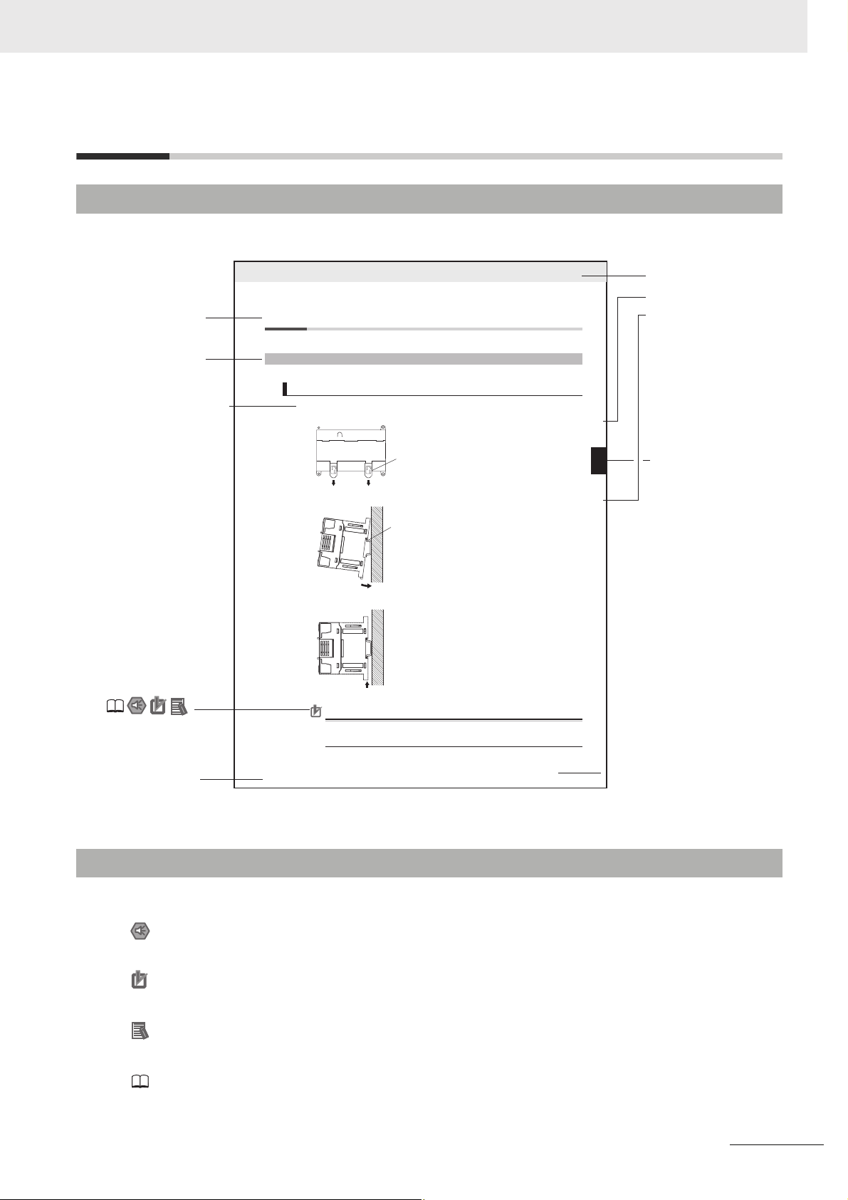
Page Structure and Icons
The following page structure and icons are used in this manual.
Level 2 heading
Level 3 heading
Step in a procedure
Indicates a step in a
procedure.
Special Information
(See below.)
Icons are used to indicate
precautions and
additional information.
5-2 Installation
5-2-1 Installation Location
DIN Track Installation
1
Use a screwdriver to pull down the DIN Track mounting pins from the back of the Units to release
them, and mount the Units to the DIN Track.
Fit the back of the Units onto the DIN Track by catching the top of the Units on the Track and then
2
pressing in at the bottom of the Units, as shown below.
Press in all of the DIN Track mounting pins to securely lock the Units in place.
3
DIN Track mounting pins
5 Installation and wiring
Level 1 heading
Level 2 heading
Level 3 heading
Gives the current
headings.
5-2 Installation
DIN Track mounting pins
Release
DIN Track
5
5-2-1 Installation Location
Page tab
Gives the number
of the section.
Manual name
This illustration is provided only as a sample and may not literally appear in this manual.
Special Information
Special information in this manual is classified as follows:
Precautions for Safe Use
Precautions on what to do and what not to do to ensure using the product safely.
Precautions for Correct Use
Precautions on what to do and what not to do to ensure proper operation and performance.
Additional Information
Additional information to increase understanding or make operation easier.
References to the location of more detailed or related information.
Precautions for Correct Use
Tighten terminal block screws and cable screws to the following torques.
M4: 1.2 N·m
M3: 0.5 N·m
CP1E CPU Unit Hardware User’s Manual(W479)
5 - 3
CP1E CPU Unit Software User’s Manual(W480)
5
Page 10

Terminology and Notation
Ter m Description
E-type CPU Unit A basic model of CPU Unit that support basic control applications using instructions such
as basic, movement, arithmetic, and comparison instructions.
Basic models of CPU Units are called “E-type CPU Units” in this manual.
N-type CPU Unit An application model of CPU Unit that supports connections to Programmable Terminals,
inverters, and servo drives.
Application models of CPU Units are called “N-type CPU Units” in this manual.
NA-type CPU Unit An application model of CPU Unit that supports built-in analog and connections to Pro-
grammable Terminals, inverters, and servo drives.
Application models of CPU Units with built-in analog are called “NA-type CPU Units” in
this manual.
CX-Programmer A programming device that applies for programming and debugging PLCs.
The CX-Programmer includes the Micro PLC Edition CX-Programmer (CX-One Lite), the
CX-Programmer (CX-One) and the CX-Programmer for CP1E.
This manual describes the unique applications and functions of the Micro PLC Edition
CX-Programmer version 9.03 or higher/CX-Programmer for CP1E.
“CX-Programmer” refers to the Micro PLC Edition CX-Programmer version 9.03 or higher/
CX-Programmer for CP1E in this manual.
Note E20/30/40 and N20/30/40 CPU Units are supported by CX-Programmer version 8.2
or higher. E10/14, N14/60 and NA20 CPU Units are supported by CX-Programmer
version 9.03 or higher.
6
CP1E CPU Unit Software User’s Manual(W480)
Page 11

Sections in this Manual
111
Overview
1 11
2 12
High-speed Counters
3 13
2
3
4
5
6
7
Internal Memory
in the CPU Unit
CPU Unit Operation
Understanding
Programming
I/O Memory
I/O Allocation
PLC Setup
12
13
14
15
16
17
Pulse Outputs
PWM Outputs
Serial
Communications
Analog I/O Function
Other Functions
Ethernet
Option Board
4
5
6
7
8
9
10
14
15
16
17
18
APP
Overview of Built-in
8
9
10
CP1E CPU Unit Software User’s Manual(W480)
Functions and
Allocations
Quick-response
Inputs
Interrupts
18
A
Programming
Device Operations
Appendices
7
Page 12

CONTENTS
Introduction ...............................................................................................................1
CP1E CPU Unit Manuals...........................................................................................2
Manual Structure.......................................................................................................5
Safety Precautions..................................................................................................18
Precautions for Safe Use ........................................................................................21
Regulations and Standards....................................................................................23
Related Manuals......................................................................................................24
Section 1 Overview
1-1 CP1E Overview ........................................................................................................................ 1-2
1-1-1 Overview of Features .................................................................................................................. 1-2
1-2 Basic Operating Procedure ....................................................................................................1-3
Section 2 Internal Memory in the CPU Unit
2-1 Internal Memory in the CPU Unit............................................................................................ 2-2
2-1-1 CPU Unit Memory Backup Structure .......................................................................................... 2-2
2-1-2 Memory Areas and Stored Data ................................................................................................. 2-3
2-1-3 Transferring Data from a Programming Device........................................................................... 2-4
2-1-4 Backup ........................................................................................................................................2-4
Section 3 CPU Unit Operation
3-1 CPU Unit Operation ................................................................................................................. 3-2
3-1-1 Overview of CPU Unit Operation ................................................................................................3-2
3-1-2 CPU Unit Operating Modes.........................................................................................................3-3
3-2 Backing Up Memory ................................................................................................................ 3-5
3-2-1 CPU Unit Memory Configuration................................................................................................. 3-5
3-2-2 Backing Up Ladder Programs and PLC Setup............................................................................3-6
3-2-3 I/O Memory Backup ....................................................................................................................3-6
3-2-4 Initializing I/O Memory at Startup................................................................................................ 3-8
Section 4 Understanding Programming
4-1 Programming ........................................................................................................................... 4-2
4-1-1 User Programs............................................................................................................................4-2
4-1-2 Program Capacity ....................................................................................................................... 4-3
4-1-3 Basics of Programming...............................................................................................................4-3
4-2 Tasks, Sections, and Symbols ............................................................................................... 4-6
4-2-1 Overview of Tasks.......................................................................................................................4-6
4-2-2 Overview of Sections ..................................................................................................................4-6
4-2-3 Overview of Symbols ..................................................................................................................4-6
8
CP1E CPU Unit Software User’s Manual(W480)
Page 13

4-3 Programming Instructions...................................................................................................... 4-8
4-3-1 Basic Understanding of Instructions ........................................................................................... 4-8
4-3-2 Operands ....................................................................................................................................4-9
4-3-3 Instruction Variations................................................................................................................. 4-10
4-3-4 Execution Conditions ................................................................................................................4-10
4-3-5 Specifying Data in Operands ....................................................................................................4-12
4-3-6 Data Formats ............................................................................................................................ 4-13
4-3-7 I/O Refresh Timing....................................................................................................................4-15
4-4 Constants ............................................................................................................................... 4-16
4-5 Specifying Offsets for Addresses ........................................................................................ 4-19
4-5-1 Overview ................................................................................................................................... 4-19
4-5-2 Application Examples for Address Offsets ................................................................................ 4-21
4-6 Ladder Programming Precautions...................................................................................... 4-22
4-6-1 Special Program Sections.........................................................................................................4-22
Section 5 I/O Memory
5-1 Overview of I/O Memory Areas............................................................................................... 5-2
5-1-1 I/O Memory Areas.......................................................................................................................5-2
5-1-2 I/O Memory Area Address Notation............................................................................................5-5
5-1-3 I/O Memory Areas.......................................................................................................................5-6
5-2 I/O Bits ...................................................................................................................................... 5-7
5-3 Work Area (W) .......................................................................................................................... 5-8
5-4 Holding Area (H) ...................................................................................................................... 5-9
5-5 Data Memory Area (D) ........................................................................................................... 5-11
5-6 Timer Area (T) ........................................................................................................................ 5-13
5-7 Counter Area (C) .................................................................................................................... 5-15
5-8 Auxiliary Area (A)................................................................................................................... 5-17
5-9 Condition Flags...................................................................................................................... 5-19
5-10 Clock Pulses .......................................................................................................................... 5-21
Section 6 I/O Allocation
6-1 Allocation of Input Bits and Output Bits ............................................................................... 6-2
6-1-1 I/O Allocation...............................................................................................................................6-2
6-1-2 I/O Allocation Concepts...............................................................................................................6-3
6-1-3 Allocations on the CPU Unit........................................................................................................6-3
6-1-4 Allocations to Expansion Units and Expansion I/O Units............................................................6-4
Section 7 PLC Setup
7-1 Overview of the PLC Setup..................................................................................................... 7-2
7-2 PLC Setup Settings ................................................................................................................. 7-3
7-2-1 Startup and CPU Unit Settings ...................................................................................................7-3
7-2-2 Timing and Interrupt Settings......................................................................................................7-3
7-2-3 Input Constant Settings...............................................................................................................7-4
7-2-4 Built-in RS-232C Port..................................................................................................................7-5
7-2-5 Serial Option Port........................................................................................................................7-8
7-2-6 Built-in Inputs ............................................................................................................................7-11
7-2-7 Pulse Output 0 Settings ............................................................................................................ 7-13
7-2-8 Pulse Output 1 Settings ............................................................................................................ 7-14
7-2-9 Built-in AD/DA: Built-in Analog I/O Settings ..............................................................................7-16
CP1E CPU Unit Software User’s Manual(W480)
9
Page 14

Section 8 Overview of Built-in Functions and Allocations
8-1 Built-in Functions .................................................................................................................... 8-2
8-2 Overall Procedure for Using CP1E Built-in Functions ......................................................... 8-3
8-3 Terminal Allocations for Built-in Functions ................... ... ........ ... .... ....8-4
8-3-1 Specifying the Functions to Use.................................................................................................. 8-4
8-3-2 Selecting Functions in the PLC Setup......................................................................................... 8-4
8-3-3 Allocating Built-in Input Terminals ...............................................................................................8-6
8-3-4 Allocating Built-in Output Temrinals ............................................................................................8-8
Section 9 Quick-response Inputs
9-1 Quick-response Inputs............................................................................................................ 9-2
9-1-1 Overview .....................................................................................................................................9-2
9-1-2 Flow of Operation........................................................................................................................ 9-3
Section 10 Interrupts
10-1 Interrupts................................................................................................................................ 10-2
10-1-1 Overview ...................................................................................................................................10-2
10-2 Input Interrupts ...................................................................................................................... 10-3
10-2-1 Overview ...................................................................................................................................10-3
10-2-2 Flow of Operation......................................................................................................................10-4
10-2-3 Application Example..................................................................................................................10-7
10-3 Scheduled Interrupts........................................................................................................... 10-10
10-3-1 Overview .................................................................................................................................10-10
10-3-2 Flow of Operation....................................................................................................................10-11
10-4 Precautions for Using Interrupts........................................................................................ 10-13
10-4-1 Interrupt Task Priority and Order of Execution ........................................................................ 10-13
10-4-2 Related Auxiliary Area Words and Bits...................................................................................10-13
10-4-3 Duplicate Processing in each Task .........................................................................................10-13
Section 11 High-speed Counters
11-1 Overview................................................................................................................................. 11-2
11-1-1 Overview ...................................................................................................................................11-2
11-1-2 Flow of Operation......................................................................................................................11-3
11-1-3 Specifications............................................................................................................................ 11-7
11-2 High-speed Counter Inputs...................................................................................................11-8
11-2-1 Pulse Input Methods Settings ...................................................................................................11-8
11-2-2 Counting Ranges Settings ......................................................................................................11-10
11-2-3 Reset Methods........................................................................................................................11-11
11-2-4 Reading the Present Value .....................................................................................................11-12
11-2-5 Frequency Measurement ........................................................................................................11-13
11-3 High-speed Counter Interrupts........................................................................................... 11-14
11-3-1 Overview .................................................................................................................................11-14
11-3-2 Present Value Comparison .....................................................................................................11-17
11-3-3 High-speed Counter Interrupt Instruction................................................................................11-21
11-4 Related Auxiliary Area Bits and Words ............................................................................. 11-26
11-5 Application Example .......................................................................................................... 11-27
10
CP1E CPU Unit Software User’s Manual(W480)
Page 15

Section 12 Pulse Outputs
12-1 Overview................................................................................................................................. 12-2
12-1-1 Overview................................................................................................................................... 12-2
12-1-2 Flow of Operation ..................................................................................................................... 12-3
12-1-3 Specifications.......................................................................................................................... 12-10
12-2 Positioning Control ............................................................................................................. 12-11
12-2-1 Positioning Control Configuration ........................................................................................... 12-11
12-2-2 Relative Positioning and Absolute Positioning ........................................................................ 12-11
12-2-3 Application Example............................................................................................................... 12-13
12-3 Jogging................................................................................................................................. 12-15
12-3-1 High-speed Jogging................................................................................................................ 12-15
12-3-2 Low-speed Jogging................................................................................................................. 12-15
12-3-3 Application Example............................................................................................................... 12-15
12-4 Defining Origin Position...................................................................................................... 12-18
12-4-1 Origin Searches...................................................................................................................... 12-18
12-4-2 Flow of Operation ................................................................................................................... 12-19
12-4-3 Settings in PLC Setup............................................................................................................. 12-19
12-4-4 Origin Search Instructions ...................................................................................................... 12-22
12-4-5 Origin Search Operations....................................................................................................... 12-23
12-4-6 Origin Return .......................................................................................................................... 12-30
12-4-7 Changing the Present Value of the Pulse Output................................................................... 12-31
12-5 Reading the Pulse Output Present Value .......................................................................... 12-32
12-6 Related Auxiliary Area Flags .............................................................................................. 12-33
12-7 Application Examples ......................................................................................................... 12-34
12-7-1 Vertically Conveying PCBs (Multiple Progressive Positioning) ............................................... 12-34
12-7-2 Feeding Wrapping Material: Interrupt Feeding ....................................................................... 12-39
12-8 Precautions when Using Pulse Outputs ........................................................................... 12-42
12-9 Pulse Output Pattern........................................................................................................... 12-47
12-9-1 Speed Control (Continuous Mode) ......................................................................................... 12-47
12-9-2 Positioning Control (Independent Mode) ................................................................................ 12-49
Section 13 PWM Outputs
13-1 PWM Outputs (Variable-duty-factor Pulse Outputs)........................................................... 13-2
13-1-1 Flow of Operation ..................................................................................................................... 13-3
13-1-2 Ladder Program Example......................................................................................................... 13-3
Section 14 Serial Communications
14-1 Serial Communications......................................................................................................... 14-2
14-1-1 Types of CPU Units and Serial Ports ........................................................................................ 14-2
14-1-2 Overview of Serial Communications.........................................................................................14-3
14-2 Program-free Communications with Programmable Terminals ........................................ 14-5
14-2-1 Overview................................................................................................................................... 14-5
14-2-2 Flow of Connection................................................................................................................... 14-6
14-2-3 PLC Setup and PT System Settings......................................................................................... 14-6
14-3 No-protocol Communications with General Components................................................. 14-8
14-3-1 Overview................................................................................................................................... 14-8
14-3-2 Flow of Operation ..................................................................................................................... 14-9
14-3-3 PLC Setup ................................................................................................................................ 14-9
14-3-4 Related Auxiliary Area Bits and Words................................................................................... 14-10
14-4 Modbus-RTU Easy Master Function .................................................................................. 14-11
14-4-1 Overview................................................................................................................................. 14-11
14-4-2 Flow of Operation ................................................................................................................... 14-11
CP1E CPU Unit Software User’s Manual(W480)
11
Page 16

14-4-3 Setting and Word Allocation....................................................................................................14-12
14-4-4 Programming Examples..........................................................................................................14-14
14-5 Serial PLC Links .................................................................................................................. 14-20
14-5-1 Overview .................................................................................................................................14-20
14-5-2 Flow of Operation....................................................................................................................14-21
14-5-3 PLC Setup...............................................................................................................................14-21
14-5-4 Operating Specifications .........................................................................................................14-23
14-5-5 Example Application................................................................................................................14-28
14-6 Connecting the Host Computer (Not Including Support Software) ................................ 14-30
14-6-1 Overview .................................................................................................................................14-30
14-6-2 Flow of Operation....................................................................................................................14-30
14-6-3 Command/response Format and List of Commands ..............................................................14-31
Section 15 Analog I/O Function
15-1 Overview................................................................................................................................. 15-2
15-1-1 Flow of Operation......................................................................................................................15-2
15-1-2 Analog I/O Specifications..........................................................................................................15-6
15-2 Analog Input and Output Signal Ranges............................................................................. 15-7
15-2-1 Analog Input Signal Ranges......................................................................................................15-7
15-2-2 Analog Output Signal Ranges...................................................................................................15-9
15-2-3 Special functions..................................................................................................................... 15-11
15-3 I/O Allocation and Related Auxiliary Area Flags............................................................... 15-12
15-3-1 I/O Allocation...........................................................................................................................15-12
15-3-2 Related Auxiliary Area Flags...................................................................................................15-12
Section 16 Other Functions
16-1 PID Temperature Control ...................................................................................................... 16-2
16-1-1 Overview ...................................................................................................................................16-2
16-1-2 Flow of Operation......................................................................................................................16-3
16-1-3 Application Example..................................................................................................................16-4
16-2 Clock ....................................................................................................................................... 16-7
16-3 DM Backup Function ............................................................................................................. 16-8
16-3-1 Backing Up and Restoring DM Area Data.................................................................................16-8
16-3-2 Procedure................................................................................................................................16-10
16-4 Security Functions .............................................................................................................. 16-12
16-4-1 Ladder Program Read Protection ...........................................................................................16-12
Section 17 Ethernet Option Board
17-1 Features and Specifications.................................................................................................17-2
17-1-1 Ethernet Option Board Function Guide.....................................................................................17-2
17-1-2 Features.................................................................................................................................... 17-3
17-1-3 Specifications............................................................................................................................ 17-5
17-1-4 Software Configuration..............................................................................................................17-5
17-1-5 FINS Communications..............................................................................................................17-6
17-1-6 Differences in version of the Ethernet Option Board................................................................. 17-8
17-2 Startup Procedure ................................................................................................................. 17-9
17-2-1 Startup Procedure.....................................................................................................................17-9
17-3 Settings ................................................................................................................................ 17-11
17-3-1 Ethernet Option Board Setup..................................................................................................17-11
17-3-2 Transferring Data from the CPU Unit ......................................................................................17-12
17-3-3 Default Settings.......................................................................................................................17-13
12
CP1E CPU Unit Software User’s Manual(W480)
Page 17

17-3-4 Web Browser Setting Function ............................................................................................... 17-15
17-4 Memory Allocations ............................................................................................................ 17-25
17-4-1 DM Area Allocation................................................................................................................. 17-25
17-4-2 CIO Area Allocation................................................................................................................ 17-30
17-5 Trouble Shooting ................................................................................................................. 17-32
17-5-1 Error Log................................................................................................................................. 17-32
17-5-2 Error Codes ............................................................................................................................ 17-33
17-5-3 Error Status............................................................................................................................. 17-35
17-6 Connection Method with the CX-Programmer.................................................................. 17-36
17-7 Network Installation............................................................................................................. 17-39
17-7-1 Devices Required for Constructing a Network........................................................................ 17-39
17-7-2 Network Installation ................................................................................................................ 17-39
17-8 Comparison with Previous Models .................................................................................... 17-41
Section 18 Programming Device Operations
18-1 Programming Devices Usable with the CP1E ..................................................................... 18-2
18-2 Overview of CX-Programmer................................................................................................ 18-3
18-2-1 CX-Programmer........................................................................................................................ 18-3
18-2-2 CX-Programmer Flow from Startup to Operation ..................................................................... 18-3
18-2-3 Help .......................................................................................................................................... 18-6
18-3 Creating a Ladder Program .................................................................................................. 18-7
18-3-1 Inputting a Ladder Program...................................................................................................... 18-7
18-3-2 Saving and Reading Ladder Programs................................................................................... 18-14
18-3-3 Editing Ladder Programs ........................................................................................................ 18-15
18-4 Connecting Online to the CP1E and Transferring the Program ...................................... 18-18
18-4-1 Connecting Online.................................................................................................................. 18-18
18-4-2 Changing Operating Modes.................................................................................................... 18-19
18-4-3 Transferring a Ladder Program and the PLC Setup................................................................ 18-20
18-4-4 Starting Operation .................................................................................................................. 18-21
18-5 Online Monitoring and Debugging..................................................................................... 18-23
18-5-1 Monitoring Status.................................................................................................................... 18-23
18-5-2 Force-set/Reset Bits............................................................................................................... 18-25
18-5-3 Online Editing ......................................................................................................................... 18-26
Section A Appendices
A-1 Instruction Functions..............................................................................................................A-2
A-1-1 Sequence Input Instructions.......................................................................................................A-2
A-1-2 Sequence Output Instructions ....................................................................................................A-3
A-1-3 Sequence Control Instructions ...................................................................................................A-5
A-1-4 Timer and Counter Instructions .................................................................................................. A-7
A-1-5 Comparison Instructions...........................................................................................................A-10
A-1-6 Data Movement Instructions .....................................................................................................A-12
A-1-7 Data Shift Instructions ..............................................................................................................A-15
A-1-8 Increment/Decrement Instructions............................................................................................ A-17
A-1-9 Symbol Math Instructions .........................................................................................................A-18
A-1-10 Conversion Instructions ............................................................................................................A-22
A-1-11 Logic Instructions...................................................................................................................... A-26
A-1-12 Special Math Instructions .........................................................................................................A-27
A-1-13 Floating-point Math Instructions ...............................................................................................A-27
A-1-14 Table Data Processing Instructions ..........................................................................................A-30
A-1-15 Data Control Instructions.......................................................................................................... A-31
A-1-16 Subroutine Instructions.............................................................................................................A-35
A-1-17 Interrupt Control Instructions ....................................................................................................A-36
A-1-18 High-speed Counter/Pulse Output Instructions ........................................................................A-37
CP1E CPU Unit Software User’s Manual(W480)
13
Page 18

A-1-19 Step Instructions .......................................................................................................................A-44
A-1-20 Basic I/O Unit Instructions.........................................................................................................A-45
A-1-21 Serial Communications Instructions..........................................................................................A-49
A-1-22 Clock Instructions......................................................................................................................A-50
A-1-23 Failure Diagnosis Instructions ...................................................................................................A-51
A-1-24 Other Instructions......................................................................................................................A-51
A-2 Auxiliary Area Allocations by Address................................................................................A-52
A-2-1 Read-only Words ......................................................................................................................A-52
A-2-2 Read/Write Words.....................................................................................................................A-70
A-3 Response Performance.........................................................................................................A-80
A-3-1 I/O Response Time...................................................................................................................A-80
A-3-2 Interrupt Response Time ..........................................................................................................A-82
A-3-3 Serial PLC Link Response Performance...................................................................................A-83
A-3-4 Pulse Output Start Time............................................................................................................A-84
A-3-5 Pulse Output Change Response Time......................................................................................A-84
A-4 PLC Operation for Power Interruptions ...............................................................................A-85
Index ..................................................................................................................................Index-1
Revision History ................................................................................Revision-1
14
CP1E CPU Unit Software User’s Manual(W480)
Page 19

Read and Understand this Manual
Please read and understand this manual before using the product. Please consult your OMRON representative
if you have any questions or comments.
Warranty and Limitations of Liability
WARRANTY
OMRON’s exclusive warranty is that the products are free from defects in materials and workmanship for a
period of one year (or other period if specified) from date of sale by OMRON.
OMRON MAKES NO WARRANTY OR REPRESENTATION, EXPRESS OR IMPLIED, REGARDING NONINFRINGEMENT, MERCHANTABILITY, OR FITNESS FOR PARTICULAR PURPOSE OF THE
PRODUCTS. ANY BUYER OR USER ACKNOWLEDGES THAT THE BUYER OR USER ALONE HAS
DETERMINED THAT THE PRODUCTS WILL SUITABLY MEET THE REQUIREMENTS OF THEIR
INTENDED USE. OMRON DISCLAIMS ALL OTHER WARRANTIES, EXPRESS OR IMPLIED.
LIMITATIONS OF LIABILITY
OMRON SHALL NOT BE RESPONSIBLE FOR SPECIAL, INDIRECT, OR CONSEQUENTIAL DAMAGES,
LOSS OF PROFITS OR COMMERCIAL LOSS IN ANY WAY CONNECTED WITH THE PRODUCTS,
WHETHER SUCH CLAIM IS BASED ON CONTRACT, WARRANTY, NEGLIGENCE, OR STRICT
LIABILITY.
In no event shall the responsibility of OMRON for any act exceed the individual price of the product on which
liability is asserted.
IN NO EVENT SHALL OMRON BE RESPONSIBLE FOR WARRANTY, REPAIR, OR OTHER CLAIMS
REGARDING THE PRODUCTS UNLESS OMRON’S ANALYSIS CONFIRMS THAT THE PRODUCTS
WERE PROPERLY HANDLED, STORED, INSTALLED, AND MAINTAINED AND NOT SUBJECT TO
CONTAMINATION, ABUSE, MISUSE, OR INAPPROPRIATE MODIFICATION OR REPAIR.
CP1E CPU Unit Software User’s Manual(W480)
15
Page 20

Application Considerations
SUITABILITY FOR USE
OMRON shall not be responsible for conformity with any standards, codes, or regulations that apply to the
combination of products in the customer’s application or use of the products.
At the customer’s request, OMRON will provide applicable third party certification documents identifying
ratings and limitations of use that apply to the products. This information by itself is not sufficient for a
complete determination of the suitability of the products in combination with the end product, machine,
system, or other application or use.
The following are some examples of applications for which particular attention must be given. This is not
intended to be an exhaustive list of all possible uses of the products, nor is it intended to imply that the uses
listed may be suitable for the products:
• Outdoor use, uses involving potential chemical contamination or electrical interference, or conditions or
uses not described in this manual.
• Nuclear energy control systems, combustion systems, railroad systems, aviation systems, medical
equipment, amusement machines, vehicles, safety equipment, and installations subject to separate
industry or government regulations.
• Systems, machines, and equipment that could present a risk to life or property.
Please know and observe all prohibitions of use applicable to the products.
NEVER USE THE PRODUCTS FOR AN APPLICATION INVOLVING SERIOUS RISK TO LIFE OR
PROPERTY WITHOUT ENSURING THAT THE SYSTEM AS A WHOLE HAS BEEN DESIGNED TO
ADDRESS THE RISKS, AND THAT THE OMRON PRODUCTS ARE PROPERLY RATED AND INSTALLED
FOR THE INTENDED USE WITHIN THE OVERALL EQUIPMENT OR SYSTEM.
PROGRAMMABLE PRODUCTS
OMRON shall not be responsible for the user’s programming of a programmable product, or any
consequence thereof.
16
CP1E CPU Unit Software User’s Manual(W480)
Page 21

Disclaimers
CHANGE IN SPECIFICATIONS
Product specifications and accessories may be changed at any time based on improvements and other
reasons.
It is our practice to change model numbers when published ratings or features are changed, or when
significant construction changes are made. However, some specifications of the products may be changed
without any notice. When in doubt, special model numbers may be assigned to fix or establish key
specifications for your application on your request. Please consult with your OMRON representative at any
time to confirm actual specifications of purchased products.
DIMENSIONS AND WEIGHTS
Dimensions and weights are nominal and are not to be used for manufacturing purposes, even when
tolerances are shown.
PERFORMANCE DATA
Performance data given in this manual is provided as a guide for the user in determining suitability and does
not constitute a warranty. It may represent the result of OMRON’s test conditions, and the users must
correlate it to actual application requirements. Actual performance is subject to the OMRON Warranty and
Limitations of Liability.
ERRORS AND OMISSIONS
The information in this manual has been carefully checked and is believed to be accurate; however, no
responsibility is assumed for clerical, typographical, or proofreading errors, or omissions.
CP1E CPU Unit Software User’s Manual(W480)
17
Page 22
Safety Precautions
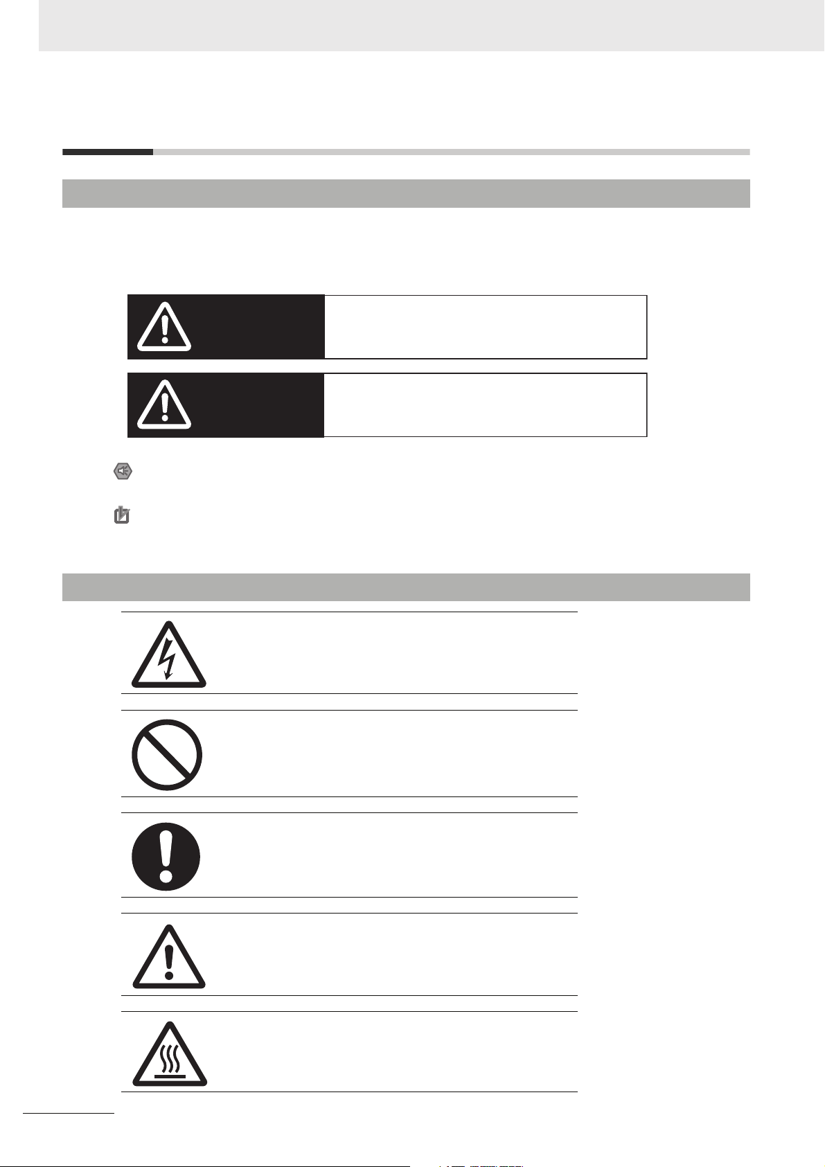
Definition of Precautionary Information
The following notation is used in this manual to provide precautions required to ensure safe usage of a
CP-series PLC. The safety precautions that are provided are extremely important to safety. Always read
and heed the information provided in all safety precautions.
Indicates an imminently hazardous situation which,
WARNING
Caution
if not avoided, will result in death or serious injury.
Additionally, there may be severe property damage.
Indicates a potentially hazardous situation which,
if not avoided, may result in minor or moderate
injury, or property damage.
Precautions for Safe Use
Indicates precautions on what to do and what not to do to ensure using the product safely.
Precautions for Correct Use
Indicates precautions on what to do and what not to do to ensure proper operation
and performance.
Symbols
The triangle symbol indicates precautions (including
warnings). The specific operation is shown in the triangle
and explained in text. This example indicates a precaution for electric shock.
The circle and slash symbol indicates operations that you
must not do. The specific operation is shown in the circle
and explained in text.
The filled circle symbol indicates operations that you
must do. The specific operation is shown in the circle and
explained in text. This example shows a general precaution for something that you must do.
18
The triangle symbol indicates precautions (including
warnings). The specific operation is shown in the triangle
and explained in text. This example indicates a general
precaution.
The triangle symbol indicates precautions (including
warnings). The specific operation is shown in the triangle
and explained in text. This example indicates a precaution for hot surfaces.
CP1E CPU Unit Software User’s Manual(W480)
Page 23
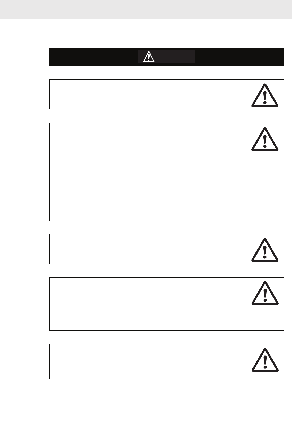
CautionCaution
Be sure to sufficiently confirm the safety at the destination when you transfer
the program or I/O memory or perform procedures to change the I/O memory.
Devices connected to PLC outputs may incorrectly operate regardless of the operating mode of the CPU Unit.
With an E-type CPU Unit or with an N/NA-type CPU Unit without a Battery, the contents of the DM Area (D) *, Holding Area (H), the Counter Present Values (C), the status of Counter Completion Flags (C), and the status of bits in the Auxiliary Area (A)
related to clock functions may be unstable when the power supply is turned ON.
*This does not apply to areas backed up to EEPROM using the DM backup function.
If the DM backup function is being used, be sure to use one of the following methods
for initialization.
1. Clearing All Areas to All Zeros
Select the Clear Held Memory (HR/DM/CNT) to Zero Check Box in the Startup
Data Read Area in the PLC Setup.
2. Clearing Specific Areas to All Zeros or Initializing to Specific Values
Make the settings from a ladder program.
If the data is not initialized, the unit or device may operate unexpectedly because of
unstable data.
Execute online edit only after confirming that no adverse effects will be caused
by extending the cycle time.
Otherwise, the input signals may not be readable.
The DM Area (D), Holding Area (H), Counter Completion Flags (C), and Counter
Present Values (C) will be held by the Battery if a Battery is mounted in a CP1EN/NAD- CPU Unit. When the battery voltage is low, however, I/O memory
areas that are held (including the DM, Holding, and Counter Areas) will be unstable.
The unit or device may operate unexpectedly because of unstable data.
Use the Battery Error Flag or other measures to stop outputs if external outputs are performed from a ladder program based on the contents of the DM
Area or other I/O memory areas.
Sufficiently check safety if I/O bit status or present values are monitored in the
Ladder Section Pane or present values are monitored in the Watch Pane.
If bits are set, reset, force-set, or force-reset by inadvertently pressing a shortcut key,
devices connected to PLC outputs may operate incorrectly regardless of the operating mode.
CP1E CPU Unit Software User’s Manual(W480)
19
Page 24
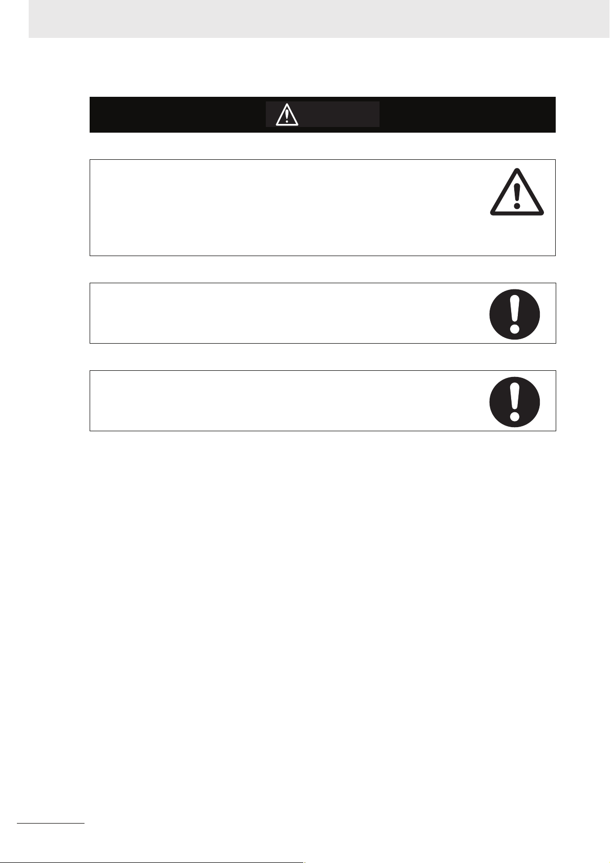
Caution
Program so that the memory area of the start address is not exceeded when
using a word address or symbol for the offset.
For example, write the program so that processing is executed only when the indirect
specification does not cause the final address to exceed the memory area by using
an input comparison instruction or other instruction.
If an indirect specification causes the address to exceed the area of the start address,
the system will access data in other area, and unexpected operation may occur.
Set the temperature range according to the type of temperature sensor connected to the Unit.
Temperature data will not be converted correctly if the temperature range does not
match the sensor.
Do not set the temperature range to any values other than those for which temperature ranges are given in the following table.
An incorrect setting may cause operating errors.
20
CP1E CPU Unit Software User’s Manual(W480)
Page 25

Precautions for Safe Use
Observe the following precautions when using a CP-series PLC.
Handling
• To initialize the DM Area, back up the initial contents for the DM Area to backup memory using
one of the following methods.
• Set the number of words of the DM Area to be backed up starting with D0 in the Number of CH
of DM for backup Box in the Startup Data Read Area.
• Include programming to back up specified words in the DM Area to built-in EEPROM by turning
ON A751.15 (DM Backup Save Start Bit).
• Check the ladder program for proper execution before actually running it on the Unit. Not checking
the program may result in an unexpected operation.
• The ladder program and parameter area data in the CP1E CPU Units are backed up in the built-in
EEPROM backup memory. The BKUP indicator will light on the front of the CPU Unit when the
backup operation is in progress. Do not turn OFF the power supply to the CPU Unit when the
BKUP indicator is lit. The data will not be backed up if power is turned OFF and a memory error
will occur the next time the power supply is turned ON.
• With a CP1E CPU Unit, data memory can be backed up to the built-in EEPROM backup memory.
The BKUP indicator will light on the front of the CPU Unit when backup is in progress. Do not turn
OFF the power supply to the CPU Unit when the BKUP indicator is lit. If the power is turned OFF
during a backup, the data will not be backed up and will not be transferred to the DM Area in RAM
the next time the power supply is turned ON.
• Before replacing the battery, supply power to the CPU Unit for at least 30 minutes and then complete battery replacement within 5 minutes. Memory data may be corrupted if this precaution is
not observed.
• The equipment may operate unexpectedly if inappropriate parameters are set. Even if the appropriate parameters are set, confirm that equipment will not be adversely affected before transferring the parameters to the CPU Unit.
• Before starting operation, confirm that the contents of the DM Area is correct.
• After replacing the CPU Unit, make sure that the required data for the DM Area, Holding Area, and
other memory areas has been transferred to the new CPU Unit before restarting operation.
• Do not attempt to disassemble, repair, or modify any Units. Any attempt to do so may result in malfunction, fire, or electric shock.
• Confirm that no adverse effect will occur in the system before attempting any of the following. Not
doing so may result in an unexpected operation.
• Changing the operating mode of the PLC (including the setting of the startup operating mode).
• Force-setting/force-resetting any bit in memory.
• Changing the present value of any word or any set value in memory.
External Circuits
• Always configure the external circuits to turn ON power to the PLC before turning ON power to the
control system. If the PLC power supply is turned ON after the control power supply, temporary
errors may result in control system signals because the output terminals on DC Output Units and
other Units will momentarily turn ON when power is turned ON to the PLC.
• Fail-safe measures must be taken by the customer to ensure safety in the event that outputs from
output terminals remain ON as a result of internal circuit failures, which can occur in relays, transistors, and other elements.
CP1E CPU Unit Software User’s Manual(W480)
21
Page 26

• If the I/O Hold Bit is turned ON, the outputs from the PLC will not be turned OFF and will maintain
their previous status when the PLC is switched from RUN or MONITOR mode to PROGRAM
mode. Make sure that the external loads will not produce dangerous conditions when this occurs.
(When operation stops for a fatal error, including those produced with the FALS instruction, all outputs from PLC will be turned OFF and only the internal output status in the CPU Unit will be maintained.)
22
CP1E CPU Unit Software User’s Manual(W480)
Page 27

Regulations and Standards
Trademarks
SYSMAC is a registered trademark for Programmable Controllers made by OMRON Corporation.
CX-One is a registered trademark for Programming Software made by OMRON Corporation.
Windows is a registered trademark of Microsoft Corporation.
Other system names and product names in this document are the trademarks or registered trademarks
of their respective companies.
CP1E CPU Unit Software User’s Manual(W480)
23
Page 28

Related Manuals
The following manuals are related to the CP1E. Use them together with this manual.
Manual name Cat. No. Model numbers Application Contents
SYSMAC CP Series
CP1E CPU Unit Software User’s Manual
(this manual)
SYSMAC CP Series
CP1E CPU Unit Hardware User’s Manual
SYSMAC CP Series
CP1E CPU Unit Instructions Reference Manual
CS/CJ/CP/NSJ Series
Communications Commands Reference Manual
SYSMAC CP Series
CP1L/CP1E CPU Unit
Introduction M anual
W480 CP1E-ED-
W479 CP1E-ED-
W483 CP1E-ED-
W342 CS1G/H-CPUH
W461 CP1L-L10D-
CP1E-ND-
CP1E-NAD-
CP1E-ND-
CP1E-NAD-
CP1E-ND-
CP1E-NAD-
CS1G/H-CPU-V1
CS1D-CPUH
CS1D-CPUS
CS1W-SCU-V1
CS1W-SCB-V1
CJ1G/H-CPUH
CJ1G-CPUP
CJ1M-CPU
CJ1G-CPU
CJ1W-SCU-V1
CP1L-L14D-
CP1L-L20D-
CP1L-M30D-
CP1L-M40D-
CP1L-M60D-
CP1E-ED-
CP1E-ND-
CP1E-NAD-
To learn the software
specifications of the
CP1E PLCs
Use this manual together with the CP1E CPU Unit Hardware User’s
Manual (Cat. No. W479) and Instructions Reference Manual (Cat. No.
W483).
To learn the hardware specifications
of the CP1E PLCs
Use this manual together with the CP1E CPU Unit Software User’s
Manual (Cat. No. W480) and Instructions Reference Manual (Cat. No.
W483).
To learn programming instructions in
detail
To learn communications commands for
CS/CJ/CP/NSJseries Controllers in
detail
Note This manual describes commands addressed to CPU Units. It
does not cover commands addressed to other Units or por ts (e.g.,
serial communications ports on CPU Units, communications ports
on Serial Communications Units/Boards, and other Communications Units).
To learn the basic
setup methods of the
CP1L/CP1E PLCs
Describes the following information for CP1E
PLCs.
• CPU Unit operation
• Internal memory
• Programming
• Settings
• CPU Unit built-in functions
• Interrupts
• High-speed counter inputs
• Pulse outputs
• Serial communications
• Analog I/O function
• Other functions
Describes the following information for CP1E
PLCs.
• Overview and features
• Basic system configuration
• Part names and functions
• Installation and settings
• Troubleshooting
Describes each programming instruction in
detail.
When programming, use this manual together
with the CP1E CPU Unit Software User’s Manual (Cat. No. W480).
Describes
1) C-mode commands and
2) FINS commands in detail.
R
ead this manual for details on C-mode and
FINS commands addressed to CPU Units.
Describes the following information for
CP1L/CP1E PLCs.
• Basic configuration and component names
• Mounting and wiring
• Programming, data transfer, and debugging
using the CX-Programmer
• Application program examples
24
CP1E CPU Unit Software User’s Manual(W480)
Page 29

Overview
This section gives an overview of the CP1E and describes its procedures.
1-1 CP1E Overview . . . . . . . . . . . . . . . . . . . . . . . . . . . . . . . . . . . . . . . . . . . . . . . . 1-2
1-2 Basic Operating Procedure . . . . . . . . . . . . . . . . . . . . . . . . . . . . . . . . . . . . . . 1-3
1
1
1-1-1 Overview of Features . . . . . . . . . . . . . . . . . . . . . . . . . . . . . . . . . . . . . . . . . . . . 1-2
CP1E CPU Unit Software User’s Manual(W480)
1-1
Page 30
1 Overview
1-1 CP1E Overview
1-1-1 Overview of Features
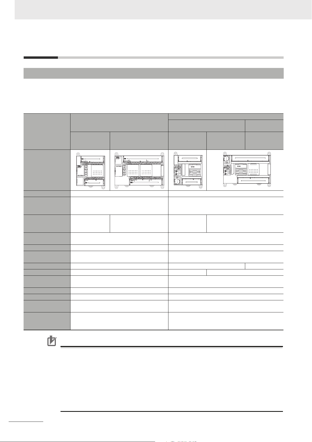
The SYSMAC CP1E Programmable Controller is a package-type PLC made by OMRON that i
designed for easy application. The CP1E includes E-type CPU Units (basic models) for standard control
operations using basic, movement, arithmetic, and comparison instructions, and N/NA-type CPU Units
(application models) that supports connections to Programmable Terminals, Inverters, and Servo Drives.
Basic Models
(E-type CPU Units)
CPU with 10, 14
or 20 I/O Points
Appearance
Program capacity 2K steps 8K steps
DM Area capacity 2K words
Of these 1,500 words can be written to the
built-in EEPROM.
Mounting Expansion I/O Units and
Expansion Units
Model with transistor outputs
Pulse outputs Not supported. Supported (Model with transistor outputs only)
Built-in serial communications port
Built-in analog Not available. Not available. Available
Option Board Not supported. Not supported. Supported (for one port)
Connection port for
Programming Device
Clock Not provided. Provided
Using a Battery Cannot be used. Can be used (sold separately).
Backup time of
built-in capacitor
Battery-free operation
Not possible. 3 Units maximum Not possible. 3 Units maximum
Available (CPU Unit with 10 I/O points only) Available
Not provided. RS-232C port provided
USB port USB port
50 hours at 25°C 40 hours at 25°C
Always battery-free operation.
Only data in the built-in EEPROM will be retained
if power is interrupted for longer than 50 hours.
CPU Unit with 30 or 40
I/O Points
CPU with 14 or
20 I/O Points
8K words
Of these 7,000 words can be written to the built-in
EEPROM.
Battery-free operation if no battery is attached. Only
data in the built-in EEPROM will be retained if power is
interrupted for longer than 40 hours.
CP1E Application Models
N-type CPU Units
CPU Unit with
30, 40 or 60 I/O
Points
NA-type CPU
Units
CPU Unit with
20 I/O Points
s
1-2
Precautions for Correct UsePrecautions for Correct Use
For CP1E CPU Units, the following I/O memory area will be unstable after a power interruption.
• DM Area (D) (excluding words backed up to the EEPROM using the DM function)
• Holding Area (H)
• Counter Present Values and Completion Flags (C)
• Auxiliary Area related to clock functions(A)
Mount the CP1W-BAT01 Battery (sold separately) to an N/NA-type CPU Unit if data in the above
areas need to be retained after a power interruption. A Battery cannot be mounted to an E-type
CPU Unit.
CP1E CPU Unit Software User’s Manual(W480)
Page 31

1-2 Basic Operating Procedure
In general, use the following procedure.
1. Setting Devices and Hardware
Connect the CPU Unit, Expansion I/O Units, and Expansion Units.
Set the DIP switches on the Option Board and Expansion Units as required.
Refer to Section 3 Part Names and Functions and Section 5 Installation and Wiring in the CP1E CPU Unit
Hardware User’s Manual (Cat. No. W479).
2. Wiring
Wire the power supply, I/O, and communications.
Refer to Section 5 Installation and Wiring in the CP1E CPU Unit Hardware User’s Manual (Cat. No. W479).
3. Connecting Online to the PLC
Connect the personal computer online to the PLC.
Refer to Section 4 Programming Device in the CP1E CPU Unit Hardware User’s Manual (Cat. No. W479).
1 Overview
1-2 Basic Operating Procedure
1
4. I/O Allocations
Allocations for built-in I/O on the CPU Unit are predetermined and memory is allocated automatically
to Expansion I/O Units and Expansion Units, so the user does not have to do anything.
Refer to Section 6 I/O Allocation in the CP1E CPU Unit Software User’s Manual (Cat. No. W480).
5. Software Setup
Make the PLC software settings.
With a CP1E CPU Unit, all you have to do is set the PLC Setup.
When using an E-type CPU Unit or when using an N/NA-type CPU Unit without a Battery, be sure to
consider selecting the Clear retained memory area (HR/DM/CNT) Check Box in the Startup Data
Read Area in the PLC Settings.
Refer to 3-2-4 Initializing I/O Memory at Startup, Section 7 PLC Setup in the CP1E CPU Unit Software
User’s Manual (Cat. No. W480).
6. Writing the Programs
Write the programs using the CX-Programmer.
Refer to Section 4 Programming Concepts in the CP1E CPU Unit Software User’s Manual (Cat. No. W480).
7. Checking Operation
Check the I/O wiring and the Auxiliary Area settings, and perform trial operation.
The CX-Programmer can be used for monitoring and debugging.
Refer to Section 8 Overview and Allocation of Built-in Functions.
8. Basic Program Operation
Set the operating mode to RUN mode to start operation.
CP1E CPU Unit Software User’s Manual(W480)
1-3
Page 32

1 Overview
1-4
CP1E CPU Unit Software User’s Manual(W480)
Page 33

2
Internal Memory in the CPU Unit
This section describes the types of internal memory in a CP1E CPU Unit and the data
that is stored.
2-1 Internal Memory in the CPU Unit . . . . . . . . . . . . . . . . . . . . . . . . . . . . . . . . . . 2-2
2-1-1 CPU Unit Memory Backup Structure . . . . . . . . . . . . . . . . . . . . . . . . . . . . . . . . 2-2
2-1-2 Memory Areas and Stored Data . . . . . . . . . . . . . . . . . . . . . . . . . . . . . . . . . . . . 2-3
2-1-3 Transferring Data from a Programming Device. . . . . . . . . . . . . . . . . . . . . . . . . 2-4
2-1-4 Backup . . . . . . . . . . . . . . . . . . . . . . . . . . . . . . . . . . . . . . . . . . . . . . . . . . . . . . . 2-4
2
CP1E CPU Unit Software User’s Manual(W480)
2-1
Page 34

2 Internal Memory in the CPU Unit
2-1 Internal Memory in the CPU Unit
2-1-1 CPU Unit Memory Backup Structure
The internal memory in the CPU Unit consists of built-in RAM and built-in EEPROM. The built-in RAM is
used as execution memory and the built-in EEPROM is used as backup memory.
CPU Unit
Built-in EEPROM Built-in RAM
Backup memory
User Program Area
(Backup)
PLC Setup PLC Setup
DM Area DM Area
Data is retained even if the power
supply is interrupted for longer
than the backup time of the built-in
capacitor.
Built-in RAM
Execution Memory
Automatic backup
Read at startup
Automatic backup
Read at startup
Backup using bit in Auxiliary Area
DM Area data read at startup
If a CP1W-BAT01 Battery (sold
separately) is mounted to an N/NA-type
CPU Unit, which is normally backed up
by a built-in capacitor, data will be
backed up by the battery.
User Program Area
I/O Memory Areas
Area where data is backed up
even if the power supply is
interrupted for longer than the
back-up time of the built-in
capacitor. *
Area where data is cleared if
the power supply is
interrupted for longer than the
back-up time of the built-in
capacitor. *
* E-type CPU Units: 50 hours at 25,
N/NA-type CPU Units: 40 hours at 25
2-2
The built-in RAM is the execution memory for the CPU Unit.
The user programs, PLC Setup, and I/O memory are stored in the built-in RAM.
The data is unstable when the power is interrupted.
If a CP1W-BAT01 Battery (sold separately) is mounted to an N/NA-type CPU Unit, the data is backed
up by the Battery.
The user programs and parameters are backed up to the built-in EEPROM, so they are not lost.
Built-in EEPROM
The built-in EEPROM is the backup memory for user programs, PLC Setup, and Data Memory backed
up using control bits in the Auxiliary Area.
Data is retained even if the power supply is interrupted. Only the Data Memory Area words that have
been backed up using the Auxiliary Area control bits are backed up (Refer to 16-3 DM Backup Func-
tion). All data in all other words and areas is not backed up.
CP1E CPU Unit Software User’s Manual(W480)
Page 35

2 Internal Memory in the CPU Unit
CautionCaution
With an E-type CPU Unit or with an N/NA-type CPU Unit without a Battery, the contents of the DM Area (D) *, Holding Area (H), the Counter Present Values (C), the status of Counter Completion Flags (C), and the status of bits in the Auxiliary Area (A)
related to clock functions may be unstable when the power supply is turned ON.
*This does not apply to areas backed up to EEPROM using the DM backup function.
If the DM backup function is being used, be sure to use one of the following methods
for initialization.
1. Clearing All Areas to All Zeros
Select the Clear retained memory area (HR/DM/CNT) to Zero Check Box in
the Startup Data Read Area in the PLC Setup.
2. Clearing Specific Areas to All Zeros or Initializing to Specific Values
Make the settings from a ladder program.
If the data is not initialized, the unit or device may operate unexpectedly because of
unstable data.
2-1 Internal Memory in the CPU Unit
2
2-1-2 Memory Areas and Stored Data
2-1-2 Memory Areas and Stored Data
The following table lists the CPU Unit memory areas and the data stored in each area.
Memory area and stored data Details
User Program Area
User Program The User Program Area stores the object code for executing
the user program that was created using the CX-Programmer.
Symbol Table The symbol table contains symbols created using the CX-Pro-
grammer (symbol names, addresses, and I/O comments).
Comments Comments are created using the CX-Programmer and include
annotations and row comments.
Program Index The program index provides information on program sections
created using the CX-Programmer, as well as program comments.
Parameter Area Stored Stored
Setting PLC Setup Various initial settings are made in the PLC Setup using soft-
ware switches.
Refer to Section 7 PLC Setup.
I/O Memory Areas The I/O Memory Areas are used for reading and writing from
the user programs.It is partitioned into the following regions
according to purpose.
• Regions where data is cleared when power to the CPU Unit
is reset, and regions where data is retained.
• Regions where data are exchanged with other Units, and
regions that are used internally.
DM Area words backed up to backup memory (built-in
EEPROM) using control bits in the Auxiliary Area.
Built-in
RAM
Stored Stored
Stored Not stored
Stored Stored
Built-in
EEPROM
CP1E CPU Unit Software User’s Manual(W480)
2-3
Page 36

2 Internal Memory in the CPU Unit
2-1-3 Transferring Data from a Programming Device
Data that has been created using the CX-Programmer is transferred to the internal memory in the CPU
Unit as shown in the following diagram.
CX-Programmer
User-created Programs
User programs
Symbol Table
Comments and
program index
PLC Setup
PLC Memory
CIO Area, Work Area, Holding
Area, Timer Area, Counter
Area, DM Area, and Auxiliary
Area
CPU Unit
User Program Area
User programs
Symbol Table
Comments and
program index
Parameter Area
PLC Setup
I/O Memory Areas
· The CX-Programmer can be
used to set status in each I/O
memory area and to write data
to the I/O memory areas.
2-1-4 Backup
The CPU Unit will access the backup memory in the following process.
• The program or PLC Setup are transferred from the CX-Programmer.
• The program is changed during online editing.
• DM backup is operated by the Auxiliary Area.
During these processes, BKUP LED will light, indicating that the CX-Programmer is being backed up.
There are the following limitations during backup.
• The operation mode cannot be switched from PROGRAM mode to MONITOR/RUN mode.
• If the power is interrupted when the program or PLC Setup are being backed up, memory error may
occur the next time power is turned ON.
• If the power is interrupted when the DM area is being backed up, the reading of backed up DM area
will fail the next time power is turned ON.
2-4
CP1E CPU Unit Software User’s Manual(W480)
Page 37

CPU Unit Operation
This section describes the operation of the CP1E CPU Unit. Make sure that you understand the contents of this section completely before writing ladder programs.
3-1 CPU Unit Operation. . . . . . . . . . . . . . . . . . . . . . . . . . . . . . . . . . . . . . . . . . . . . 3-2
3-1-1 Overview of CPU Unit Operation . . . . . . . . . . . . . . . . . . . . . . . . . . . . . . . . . . . 3-2
3-1-2 CPU Unit Operating Modes . . . . . . . . . . . . . . . . . . . . . . . . . . . . . . . . . . . . . . . 3-3
3-2 Backing Up Memory . . . . . . . . . . . . . . . . . . . . . . . . . . . . . . . . . . . . . . . . . . . . 3-5
3-2-1 CPU Unit Memory Configuration . . . . . . . . . . . . . . . . . . . . . . . . . . . . . . . . . . . 3-5
3-2-2 Backing Up Ladder Programs and PLC Setup . . . . . . . . . . . . . . . . . . . . . . . . . 3-6
3-2-3 I/O Memory Backup . . . . . . . . . . . . . . . . . . . . . . . . . . . . . . . . . . . . . . . . . . . . . 3-6
3-2-4 Initializing I/O Memory at Startup . . . . . . . . . . . . . . . . . . . . . . . . . . . . . . . . . . . 3-8
3
3
CP1E CPU Unit Software User’s Manual(W480)
3-1
Page 38

3 CPU Unit Operation
3-1 CPU Unit Operation
This section gives an overview of the CPU Unit operation, describes the operating modes, and explains
how the Unit operates when there is a power interruption.
3-1-1 Overview of CPU Unit Operation
The CPU Unit reads and writes data to the internal I/O memory areas while executing user ladder programs by executing the instructions in order one at a time from the start to the end.
CPU Unit Internal Memory
Overhead processing
(self-diagnosis)
I/O memory
00000000
00000000
11011000
00111010
10101001
CPU Unit
processing
cycle
Program execution
Access
Change in status
after all instructions
have been executed
01010100
01101010
11001010
10111011
10001101
Exchange
Inputs
Outputs
I/O refreshing
Peripheral servicing
Refreshes external devices at this timing
Overhead Processing (Self-diagnosis)
Self-diagnosis, such as an I/O bus check, is performed.
Ladder Program Execution
Instructions are executed from the beginning of the program and I/O memory is refreshed.
I/O Refresh
Data to and from external devices, such as sensors and switches, directly connected to the built-in I/O
terminals and expansion I/O terminals, is exchanged with data in the I/O memory of the PLC. This process of data exchange is called the I/O refresh.
Peripheral Servicing
3-2
Peripheral servicing is used to communicate with devices connected to the communications port or for
exchanging data with the CX-Programmer.
Cycle Time
The cycle time is the time between one I/O refresh and the next. The cycle time can be determined
beforehand for SYSMAC PLCs.
CP1E CPU Unit Software User’s Manual(W480)
Page 39

3 CPU Unit Operation
Additional Information
The average cycle time during operation will be displayed in the status bar on the bottom right of
the Ladder Program Window on the CX-Programmer.
I/O Memory
These are the PLC memory areas that are accessed by the ladder programs. SYSMAC PLCs refer to
these areas as the I/O memory. It can be accessed by specifying instruction operands. There are words
in the I/O memory area where data is cleared and words where data is retained when recovering from a
power interruption. There are also words that can be set to be cleared or retained. Refer to Section 5
I/O Memory.
3-1 CPU Unit Operation
3-1-2 CPU Unit Operating Modes
Overview of Operating Modes
CPU Units have the following three operating modes.
PROGRAM mode: The programs are not executed in PROGRAM mode.This mode is used for the initial
settings in PLC Setup, transferring ladder programs, checking ladder programs, and
making prepartions for executing ladder programs such as force-setting/resetting bits.
MONITOR mode: In this mode, it is possible to perform online editing, force-set/reset bits, and change
I/O memory present values while the ladder programs are being executed. Adjustments during trial operation are also made in this mode.
RUN mode: This is the mode in which the ladder program is executed. Some operations are dis-
abled during this mode. It is the startup mode at initial value when the CPU Unit is
turned ON.
Changing the Operating Mode
The operating mode can be changed from the CX-Programmer.
3
3-1-2 CPU Unit Operating Modes
Changing the Startup Mode
The default operating mode when the CPU Unit is turned ON is RUN mode.
To change the startup mode to PROGRAM or MONITOR mode, set the desired mode in Startup
Setting in PLC Setup from the CX-Programmer.
CP1E CPU Unit Software User’s Manual(W480)
3-3
Page 40

3 CPU Unit Operation
Changing the Operating Mode after Startup
Use one of the following procedures.
• Select PROGRAM, MONITOR, or RUN from the Startup Mode Menu.
• Right-click the PLC in the project tree, and then select PROGRAM, MONITOR, or RUN from the
Startup Mode Menu.
Operating Modes and Operation
The following table lists status and operations for each mode.
Operating mode PROGRAM MONITOR RUN
Ladder program execution Stopped Executed Executed
I/O refresh Executed Executed Executed
External I/O status OFF after changing to
I/O memory Non-retained memory Cleared Controlled by
Retained memory Retained
CX-Programmer operations
I/O memory monitoring Yes Yes Yes
Ladder program monitoring Yes Yes Yes
Ladder program transfer
Checking programs Yes No No
Setting the PLC Setup Yes No No
Changing ladder programs Yes Yes No
Forced-set/reset operations Yes Yes No
Changing timer/counter SV Yes Yes No
Changing timer/counter PV Yes Yes No
Change I/O memory PV Yes Yes No
Controlled by
PROGRAM mode but
can be turned ON from
the CX-Programmer
afterward.
From CPU Unit Yes Yes Yes
To CPU Unit Yes No No
the ladder pro-
grams.
the ladder pro-
grams.
Controlled by
the ladder programs.
Controlled by
the ladder programs.
3-4
The Retaining of I/O Memory When Changing the Operating Mode
Non-retained areas Retained areas
• I/O bits
• Serial PLC Link Words
Mode changes
RUN or MONITOR to
PROGRAM
PROGRAM to RUN or
MONITOR
RUN to MONITOR or
MONITOR to RUN
* The data is cleared when the IOM Hold Bit is OFF. The outputs from the Output Units will be turned OFF when a
fatal error is occurred, regardless of the status of the IOM Hold Bit, and the status of the output bits in CPU Unit’s
I/O memory is retained.
• Work bits
• Timer PV/Completion Flags
• Data Registers
(Auxiliary Area bits/words are retained or
not retained depending on the address.)
Cleared
Cleared
Retained
*
*
*
Refer to Section 5 I/O Memory for details on the I/O memory.
• Holding Area
• DM Area
• Counter PV and Completion Flags
(Auxiliary Area bits/words are
retained or not retained depending
on the address.)
Retained
Retained
Retained
CP1E CPU Unit Software User’s Manual(W480)
Page 41

3-2 Backing Up Memory
This section describes backing up the CP1E CPU Unit memory areas.
3 CPU Unit Operation
3-2-1 CPU Unit Memory Configuration
Data backup to the CP1E CPU Unit’s built-in RAM memory describes as below.
Ladder programs and PLC Setup
Automatically backed up to the built-in EEPROM whenever changed.
DM Area in the I/O memory
Data in specified words of the DM Area can be backed up to the built-in EEPROM by using bits in
the Auxiliary Area. Other words are not backed up.
Other areas in the I/O memory (including Holding Area data, Counter PVs,
and Counter Completion Flags)
Not backed up to the built-in EEPROM.
Built-in EEPROM
backup memory
Ladder programs
Changing program
CP1E CPU Unit
3-2 Backing Up Memory
3
3-2-1 CPU Unit Memory Configuration
Built-in RAM
Ladder programs
Parameter Area
PLC Setup
Part of DM Area
PLC power turned ON
PLC Setup changed
PLC power turned ON
Operation using control
bits in Auxiliary Area
PLC power turned ON
Parameter Area
PLC Setup
I/O Memory Areas
· I/O Area
· Work Area
· Holding Area
· Auxiliary Area
· Timer/Counter
Areas
· DM Area
CP1E CPU Unit Software User’s Manual(W480)
3-5
Page 42

3 CPU Unit Operation
3-2-2 Backing Up Ladder Programs and PLC Setup
Ladder programs and the PLC Setup are automatically backed up to and restored from the built-in
EEPROM backup memory.
Backing Up Memory
Ladder programs and PLC Setup are backed up to the built-in EEPROM backup memory by transferring them from the CX-Programmer or writing them using online editing.
Restoring Memory
Ladder programs and PLC Setup are automatically transferred from the built-in EEPROM backup
memory to the RAM memory when power is turned ON again or at startup.
Precautions for Safe Use
The BKUP indicator on the front of the CPU Unit turns ON when data is being written to the builtin EEPROM backup memory. Never turn OFF the power supply to the CPU Unit when the BKUP
indicator is lit.
3-2-3 I/O Memory Backup
I/O memory is backed up to the built-in EEPROM backup memory only when a bit in the Auxiliary Area
is turned ON to back up specified words in the DM Area.
Area
CIO Area Not backed up. Cleared to all zeros.
Work Area (W)
Timer Area (T)
Holding Area (H) Unstable when the power
Counter Area (C)
Auxiliary Area (A) Initialized (For N/NA-type
DM Area
(D)
Number of words starting from D0 set in the
Number of CH of DM for
backup Box in the Startup Data Read Area in
the PLC Settings.
Ranges not given
above.
Backup to built-in
EEPROM backup
memory
The specified number of
words starting from D0 is
backed up by turning ON
A751.15 (DM Backup
Save Start Bit).
Not backed up. Unstable when the power
N/NA-type CPU Unit with
no Battery mounted or
E-type CPU Unit
supply is OFF for longer
than the I/O memory
backup time.
CPU Units, status of bits
related to clock functions
is unstable when the
power supply is OFF for
longer than the I/O mem-
ory backup time.
The specified number of words starting from D0 is
restored from the built-in EEPROM backup memory if
the Restore D0- from backup memory Check Box is
selected in the Startup Data Read Area in the PLC Settings.
supply is OFF for longer
than the I/O memory
backup time.
Status at startup
*
*
)
N/NA-type CPU Unit with
Battery mounted
The values immediately
before power interruption
are retained.
Initialized (For N/NA-type
CPU Units, status of bits
related to clock functions
are retained at their status immediately before
power interruption.)
The values immediately
before power interruption
are retained.
3-6
* The values will be cleared to all zeros at startup if the Clear retained memory area (HR/DM/CNT) Check Box is
selected in the PLC Settings.
CP1E CPU Unit Software User’s Manual(W480)
Page 43

3 CPU Unit Operation
I/O Memory Backup Time
The built-in capacitor’s backup time for I/O memory during a power interruption is listed below for E-type
CPU Units and N/NA-type CPU Units.
E-type CPU Units: 50 hours at 25°C
N/NA-type CPU Units (without a battery): 40 hours at 25°C
CP1E E-type CPU Unit
50 hours
40 hours
CP1E N/NA-type CPU Unit
without a battery
25 hours
20 hours
Backup time for I/O memory
9 hours
7 hours
3-2 Backing Up Memory
3
3-2-3 I/O Memory Backup
25˚C 40˚C 60˚C
Ambient temperature
The following areas are unstable when power is interrupted for longer than the I/O memory backup
times given above.
• DM Area (D) (excluding words backed up to the EEPROM using the DM backup function)
• Holding Area (H)
• Counter PVs and Completion Flags (C)
• Auxiliary Area related to clock function (A)
Additional Information
Words in the Auxiliary Area related to clock function are unstable. Others are cleared to default
values.
Power interruption time CPU Unit
Words Name
A100 to A199 Error Log Area Retained Unstable Supported
A300 Error Log Pointer Supported
A351 to A354 Clock Area Not supported.
A510 to A511 Startup Time Not supported.
A512 to A513 Power Interruption Time Not supported.
A514 Number of Power Interruptions Supported
A515 to A517 Operation Start Time Not supported.
A518 to A520 Operation End Time Not supported.
A720 to A749 Power ON Clock Data 1 to 10 Not supported.
Less than I/O
memory backup
time
Longer than I/O
memory backup
time
E-type CPU
Unit
N/NA-type
CPU Unit
Supported
Precautions for Correct UsePrecautions for Correct Use
Use an N/NA-type CPU Unit with a Battery mounted if it is necessary to retain the contents of the
DM Area (D) and Holding Area (A), the Counter Present Values (C), the status of Counter Completion Flags (C), and the status of bits in the Auxiliary Area (A) related to clock functions when
the power supply is turned ON after the power has been OFF for a period of time. These contents and status cannot be retained with an E-type CPU Unit.
CP1E CPU Unit Software User’s Manual(W480)
3-7
Page 44

3 CPU Unit Operation
3-2-4 Initializing I/O Memory at Startup
For E-type or N/NA-type (without a battery) CPU Units, the held areas in I/O memory (i.e., Holding
Area, Counter Present Values, Counter Completion Flags, and DM Area) may be unstable when the
power supply is turned ON. Therefore, use one of the following ways to clear these areas.
Clearing All Held Areas to Zero at Startup
Select the Clear retained memory area (HR/DM/CNT) Check Box in the PLC Settings.
Note If the Restore D0- from backup memory Check Box is selected, only the specified words in the DM Area will
be restored from the built-in EEPROM backup memory when the power supply is turned ON.
Initializing Specific Held Areas at Startup
Write the following type of ladder programming.
Example
P_First_Cycle
First Cycle Flag
(A200.11)
BSET
#0000
D100
D2047
BSET
#0000
H10
D49
CNR
C0
C255
D100 to D2047 are cleared
to Zero
H10 to H49 are cleared
to Zero
C0 to C255 are cleared
to Zero
3-8
CP1E CPU Unit Software User’s Manual(W480)
Page 45

4
Understanding Programming
This section provides basic information on ladder programming for CP1E CPU Units.
4-1 Programming . . . . . . . . . . . . . . . . . . . . . . . . . . . . . . . . . . . . . . . . . . . . . . . . . . 4-2
4-1-1 User Programs . . . . . . . . . . . . . . . . . . . . . . . . . . . . . . . . . . . . . . . . . . . . . . . . . 4-2
4-1-2 Program Capacity . . . . . . . . . . . . . . . . . . . . . . . . . . . . . . . . . . . . . . . . . . . . . . . 4-3
4-1-3 Basics of Programming. . . . . . . . . . . . . . . . . . . . . . . . . . . . . . . . . . . . . . . . . . . 4-3
4-2 Tasks, Sections, and Symbols. . . . . . . . . . . . . . . . . . . . . . . . . . . . . . . . . . . . 4-6
4-2-1 Overview of Tasks. . . . . . . . . . . . . . . . . . . . . . . . . . . . . . . . . . . . . . . . . . . . . . . 4-6
4-2-2 Overview of Sections . . . . . . . . . . . . . . . . . . . . . . . . . . . . . . . . . . . . . . . . . . . . 4-6
4-2-3 Overview of Symbols . . . . . . . . . . . . . . . . . . . . . . . . . . . . . . . . . . . . . . . . . . . . 4-6
4
4-3 Programming Instructions . . . . . . . . . . . . . . . . . . . . . . . . . . . . . . . . . . . . . . . 4-8
4-3-1 Basic Understanding of Instructions. . . . . . . . . . . . . . . . . . . . . . . . . . . . . . . . . 4-8
4-3-2 Operands . . . . . . . . . . . . . . . . . . . . . . . . . . . . . . . . . . . . . . . . . . . . . . . . . . . . . 4-9
4-3-3 Instruction Variations . . . . . . . . . . . . . . . . . . . . . . . . . . . . . . . . . . . . . . . . . . . 4-10
4-3-4 Execution Conditions . . . . . . . . . . . . . . . . . . . . . . . . . . . . . . . . . . . . . . . . . . . 4-10
4-3-5 Specifying Data in Operands . . . . . . . . . . . . . . . . . . . . . . . . . . . . . . . . . . . . . 4-12
4-3-6 Data Formats . . . . . . . . . . . . . . . . . . . . . . . . . . . . . . . . . . . . . . . . . . . . . . . . . 4-13
4-3-7 I/O Refresh Timing . . . . . . . . . . . . . . . . . . . . . . . . . . . . . . . . . . . . . . . . . . . . . 4-15
4-4 Constants. . . . . . . . . . . . . . . . . . . . . . . . . . . . . . . . . . . . . . . . . . . . . . . . . . . . 4-16
4-5 Specifying Offsets for Addresses . . . . . . . . . . . . . . . . . . . . . . . . . . . . . . . . 4-19
4-5-1 Overview. . . . . . . . . . . . . . . . . . . . . . . . . . . . . . . . . . . . . . . . . . . . . . . . . . . . . 4-19
4-5-2 Application Examples for Address Offsets . . . . . . . . . . . . . . . . . . . . . . . . . . . 4-21
4-6 Ladder Programming Precautions . . . . . . . . . . . . . . . . . . . . . . . . . . . . . . . 4-22
4-6-1 Special Program Sections . . . . . . . . . . . . . . . . . . . . . . . . . . . . . . . . . . . . . . . 4-22
CP1E CPU Unit Software User’s Manual(W480)
4-1
Page 46

4 Understanding Programming
4-1 Programming
4-1-1 User Programs
Structure of User Programs
User programs are created by using the CX-Programmer.
The user programs consist of the following parts.
• Programs
A program consists of more than one instruction and ends with an END instruction.
• Tasks (Smallest Executable Unit)
A program is assigned to an interrupt task to execute it. (In the CX-Programmer, the interrupt task
number is specified in the program properties.)
Tasks include cyclic tasks (executed with normal cyclic processing), interrupt tasks (executed when
interrupt conditions have been completed) and scheduled interrupt tasks (executed at specified intervals).
The CP1E can use only one cyclic task.
• Sections
When creating and displaying programs with the CX-Programmer, the one program can be divided
into any number of parts.
Each part is called a section.
Sections are created mainly to make programs easier to understand.
• Subroutines
You can create subroutines within a program.
User Program Data
The user programs are saved in a project file (.CXP) for the CX-Programmer along with other parameters, such as the symbol table, PLC Setup data, and I/O memory data.
Programming Languages
Programs can be written using only ladder programs.
4-2
CP1E CPU Unit Software User’s Manual(W480)
Page 47

4-1-2 Program Capacity
The maximum program capacities of the CP1E CPU Units for all ladder programs (including symbol
table and comments) are given in the following table.
The total number of steps must not exceed the maximum program capacity.
Unit type Model numbers Program capacity
E-type CPU Unit CP1E-E- 2K steps
N/NA-type CPU Unit CP1E-N/NA- 8K steps
4 Understanding Programming
It is possible to check the program size by selecting Program - Memory View in the CX-Programmer.
The size of a ladder instruction depends on the specific instruction and operands that are used.
4-1-3 Basics of Programming
This section describes the basics of programming for the CP1E.
Basic Concepts of Ladder Programming
Instructions are executed in the order that they are stored in memory (i.e., in the order of the mnemonic
code). Be sure you understand the concepts of ladder programming, and write the programs in the
proper order.
Basic Points in Creating Ladder Programs
Order of Ladder Program Execution
When the ladder diagram is executed by the CPU Unit, the execution condition (i.e., power flow)
flows from left to right and top to bottom.
The flow is different from that for circuits that consist of hard-wired control relays.
For example, when the diagram in figure A is executed by the CPU Unit, power flows as though the
diodes in brackets were inserted so that output R2 is not controlled by input condition D.
The actual order of execution is indicated on the right with mnemonics.
To achieve operation without these imaginary diodes, the diagram must be rewritten. Also, the power
flow in figure B cannot be programmed directly and must be rewritten.
4-1 Programming
4
4-1-2 Program Capacity
Figure A (Good example)
Signal flow
A
()
CD
()
E
()
Figure B (Bad example)
A
C E
CP1E CPU Unit Software User’s Manual(W480)
B
E
B
R1
R2
R1
R2
Order of execution (mnemonics)
LD A
LD C
OUT TR0
AND D
OR LD
AND B
OUT R1
LD TR0
AND E
OUT R2
4-3
Page 48

4 Understanding Programming
Number of Times Bits Can be Used and Connection Method
• There is no limit to the number of I/O bits, work bits, timers, and other input bits that can be used.
Program structure should be kept as clear and simple as possible to make the programs easier to
understand and maintain even if it means using more input bits.
• There is no limit to the number of input conditions that can be connected in series or in parallel on
the rungs.
• Two or more OUT instructions can be connected in parallel.
0.00 0.05
TIM
0000
#100
102.00
• Output bits can also be used in input conditions.
102.00
102.00
Ladder Programming Restrictions
• A rung error will occur if a ladder program is not connected to both bus bars.
The ladder program must be connected to both bus bars so that the execution condition will flow
from the left bus bar to the right bus bar.
If the rungs are not connected to both bus bars, a rung error will occur during the program check
on the CX-Programmer and program transfer will be impossible.
• A rung error will occur if the instruction shown below is made to directly connect to the bus bar
without an input condition.
OUT instructions, timers, counters, and other output instructions cannot be connected directly to
the left bus bar.
If one of these instructions is connected directly to the left bus bar, a rung error will occur and program transfer will be impossible.
4-4
MOV
CP1E CPU Unit Software User’s Manual(W480)
Page 49

4 Understanding Programming
• A location error will occur if an instruction is not connected directly to the right bus bar.
An input condition cannot be inserted after an OUT instruction or other output instruction. The
input condition must be inserted before an OUT instruction or other output instruction. If it is
inserted after an output instruction, then a location error will occur during the program check in the
CX-Programmer.
0.00 0.03 0.04
0.01
102.01
102.01
• A warning will occur if the same output bit is used more than once in an OUT instruction.
One output bit can be used in one instruction only. Instructions in a ladder program are executed
in order from the top rung in each cycle. The result of an OUT instruction in a lower rung will be
eventually saved in the output bit. The results of any previous instructions controlling the same bit
will be overwritten and not output.
Output bit CIO 100.00
Output bit CIO 100.00
4-1 Programming
4
4-1-3 Basics of Programming
CP1E CPU Unit Software User’s Manual(W480)
4-5
Page 50

4 Understanding Programming
4-2 Tasks, Sections, and Symbols
4-2-1 Overview of Tasks
There are basically two types of tasks.
Task settings must be made to use interrupt tasks with a CP1E CPU Unit.
Applicable
Task t ype Description
Cyclic task Executed once per cycle Ladder diagram Only one for the CP1E.
Interrupt tasks Executed when a specific
condition occurs. The process
being executed is interrupted.
programming
language
(Normally, the user does not have to consider this.)
Ladder diagram An interrupt task is placed into READY
status when the interrupt condition
occurs. A condition can be set for the following interrupt tasks.
• Scheduled interrupt tasks
• I/O interrupt tasks
Execution condition
4-2-2 Overview of Sections
With the CX-Programmer, programs can be created and displayed in functional units called sections.
Any program in a task can be divided into sections.
Sections improve program legibility and simplifies editing.
4-2-3 Overview of Symbols
Symbols
I/O memory area addresses or constants can be specified by using character strings registered as symbols.
The symbols are registered in the symbol table of the CX-Programmer.
Programming with symbols enables programming with names without being aware of the addresses.
The symbol table is saved in the CX-Programmer project file (.CXP) along with other parameters, such
as the user programs.
Symbol Types
There are two types of symbols that can be used in programs.
4-6
Global Symbols
Global symbols can be accessed from all ladder programs in the PLC.
Local Symbols
Local symbols can be accessed from only one task. They are assigned to individual tasks.
CP1E CPU Unit Software User’s Manual(W480)
Page 51

4 Understanding Programming
Addresses are allocated to symbols using one of the following methods.
• User Specified allocation
• Automatic allocation using the CX-Programmer
The area of memory used for automatic allocations is set by selecting Memory Allocation - Automatic Address Allocation from the PLC Menu in the CX-Programmer.
Types of sym-
bols
Global
symbols
Project tree in the
CX-Programmer
PLC tree Not
using symbols from a
possible.
Access
network
Scope
Access
from other
tasks
Possible. Possible. Supported
Access
from the
local task
Address and I/O
comment (with-
out a symbol
name)
4-2 Tasks, Sections, and Symbols
Local
symbols
Program tree Not
possible.
Possible. Not supported
Note “Global” and “local” indicate only the applicable scope of the symbol.
They have nothing to do with the applicable scope of memory addresses.
Therefore, a warning but not an error will occur in the following cases, and it will be possible to
transfer the user program.
• The same addresses is used for two different local symbols.
• The same addresses is used for a global symbol and a local symbol.
Additional Information
In programs in the CX-Programmer, global symbols and local symbols can be identified by the
following character colors and symbol icons.
Classification Display color Example (default color)
Global symbols Black (default)
Local symbols Blue (default)
Start
3.00
Error
4
4-2-3 Overview of Symbols
Select Tools - Options, and select Local Symbols or Global Symbols in Appearance to change
the color.
CP1E CPU Unit Software User’s Manual(W480)
W0.00
4-7
Page 52

4 Understanding Programming
4-3 Programming Instructions
4-3-1 Basic Understanding of Instructions
Structure of Instructions
Programs consist of instructions. The conceptual structure of the inputs to and outputs from an instruction is shown in the following diagram.
Power flow (P.F., execution condition)
Instruction condition
Instruction
Power flow (P.F., execution condition)
Instruction condition
*
1
*
2
Flags
Operands
(sources)
I/O memory
Operands
(destinations)
Flag
*1: Input instructions only.
*2: Not output for all instructions.
Power Flow
The power flow is the execution condition that is used to control the execution and instructions when
programs are executing normally. In a ladder program, power flow represents the status of the execution condition.
Input Instructions
• Load instructions indicate a logical start and outputs the execution condition.
Outputs the execution
condition.
• Intermediate instructions input the power flow as an execution condition and output the power flow
to an intermediate or output instruction.
Outputs the execution
condition.
4-8
=
D0
#1215
Output Instructions
Output instructions execute all functions, using the power flow as an execution condition.
LD power flow
Input block
Output block
Power flow for
output instruction
CP1E CPU Unit Software User’s Manual(W480)
Page 53

4-3-2 Operands
Operands specify preset instruction parameters that are used to specify I/O memory area contents or
constants. Operands are given in boxes in the ladder programs.
Addresses and constants are entered for the operands to enable executing the instructions.
Operands are classified as source, destination, or number operands.
Example:
4 Understanding Programming
4-3 Programming Instructions
MOV
&0
D0
Source operand
S (source)
D (destination)
Operand type
Specifies the address of
the data to be read or a
constant.
SBS
2
Operand
N (number)
symbol
S Source oper-
and
Description
Source operand other than control
data (C)
C Control data Compound data in a source operand
that has different meanings depending on bit status.
Destination
operand
(results)
Number Specifies a particular
Specifies the address
where data will be written.
number used in the
instruction, such as a
D −
N With numbers, it is not possible to specify an address
for indirect specification (except for jump instruction
numbers).
subroutine number.
Operands are also called the first operand, second operand, and so on, starting from the top of the
instruction.
MOV
#0
D0
First operand
Second operand
4
4-3-2 Operands
CP1E CPU Unit Software User’s Manual(W480)
4-9
Page 54

4 Understanding Programming
4-3-3 Instruction Variations
The following variations are available for instructions to differentiate executing conditions and to refresh
data when the instruction is executed (immediate refreshing).
Var iati on Symbol Description
No variation used. − These instructions are executed once every cycle while
Differentiation
variations
Immediate refreshing ! Data in the built-in I/O area specified by the operands is
Example:
!
MOV
@
ON @ These instructions are executed only once when the exe-
OFF % These instructions are executed only once when the exe-
Instruction (mnemonic)
Differentiation variation
Immediate refresh variation
the execution condition is satisfied.
cution condition turns ON.
cution condition turns OFF.
refreshed when the instruction is executed.
4-3-4 Execution Conditions
The following two types of basic and special instructions can be used.
• Non-differentiated instructions: Executed every cycle
• Differentiated instructions: Executed only once
Non-differentiated Instructions
Output Instructions (Instructions That Require Input Conditions)
These instructions are executed once every cycle while the execution condition is satisfied (ON or
OFF).
Non-differentiated
Output instructions
executed every cycle
Input Instructions (Logical Starts and Intermediate Instructions)
These instructions read bit status, make comparisons, test bits, or perform other types of processing
every cycle. If the results are ON, the input condition is output (i.e., the execution condition is turned
ON).
Example:
MOV
4-10
Input instruction executed every cycle
Example:
CP1E CPU Unit Software User’s Manual(W480)
Page 55

4 Understanding Programming
Input-differentiated Instructions
Upwardly Differentiated Instructions (Instructions Preceded by @)
• Output Instructions
The instruction is executed only during the cycle in which the execution condition changes from
OFF to ON.
The instruction is not executed in the following cycle.
4-3 Programming Instructions
@ Upwardly
differentiated
instruction
Example:
1.02
@MOV
Executes the MOV instruction once
when CIO 1.02 turns ON.
• Input Instructions (Logical Starts and Intermediate Instructions)
The instruction reads bit status, makes comparisons, tests bits, or performs other types of processing every cycle and will output an ON execution condition (power flow) when the result
changes from OFF to ON.
The execution condition will turn OFF the next cycle.
Upwardly differentiated instruction
Example:
1.03
ON execution condition created for one
cycle when CIO 1.03 turns ON.
Downwardly Differentiated Instructions (Instruction Preceded by %)
• Output Instructions
The instruction is executed only during the cycle in which the execution condition changes from
ON to OFF.
The instruction is not executed in the following cycle.
4
4-3-4 Execution Conditions
% Downwardly
differentiated
instruction
Example:
1.02
%SET
Executes the SET instruction once
when CIO 1.02 turns OFF.
• Input Instructions (Logical Starts and Intermediate Instructions)
The instruction reads bit status, makes comparisons, tests bits, or performs other types of processing every cycle and will output an ON execution condition (power flow) when the result
changes from ON to OFF.
The execution condition will turn OFF the next cycle.
Downwardly differentiated instruction
Example:
1.03
ON execution condition created for one cycle
when CIO 1.03 turns ON.
CP1E CPU Unit Software User’s Manual(W480)
4-11
Page 56

4 Understanding Programming
4-3-5 Specifying Data in Operands
Specifying Addresses
Operand Description Example
Specifying
bit
addresses
Specifying
word
addresses
Specifying
offsets for bit
addresses
The word address and bit number are specified directly to specify a bit.
.
Bit number
(00 to 15)
Word address
The word address is specified directly to
specify a 16-bit word.
Word address
In brackets, specify the number of bits to offset the specified starting bit address.
.
Offset Constant
0 to 15 or word
Starting bit address
address in I/O memory
.02
1
Bit number 02
Word address CIO 1
3
Word address CIO 3
D200
Word address D200
10.00[2]
Number of bits to offset the address
→Specify 10.02
Starting bit address
10.00 [W0]
Number of bits to offset the address
When W0 = &2→
Starting bit address
A symbol can also be specified for the starting bit address. Only Holding, Work, and DM
Area addresses can be used regardless of
whether a physical address or symbol is
used.
A constant or word address in I/O memory
can be used for the offset. If a word address
is specified, the contents of the word is used
as the offset.
Specifying
offsets for
word
addresses
In brackets, specify the number of words to
offset the specified starting bit address.
[]
Offset Constant of 0 or
higher or word address in
I/O memory
Starting word address
D0[2]
Number of words to offset the address
→Specify D2
Starting word address
D0 [W0]
Number of bits to offset the address
When W0 = &2→
Starting word address
A symbol can also be specified for the starting word address. Only Holding, Work, and
DM Area addresses can be used regardless
of whether a physical address or symbol is
used.
A constant or word address in I/O memory
can be used for the offset. If a word address
is specified, the contents of the word is used
as the offset.
Specify
Specify
Application
examples
1.02
MOV 3 D200
10.00[2]
10.02
MOV 3 D0[200]
D2
4-12
CP1E CPU Unit Software User’s Manual(W480)
Page 57

4 Understanding Programming
Operand Description Example
Specifying
indirect DM
addresses in
Binary Mode
An offset from the beginning of the DM Area
is specified. The contents of the address will
be treated as binary data (E-type CPU Unit
0000 to 2047, N/NA-type CPU Unit 0000 to
8191) to specify the word address in DM
Area.
Add the @ symbol at the front to specify an
@D300
&256 decimal
(#0100 hexadecimal)
Specify D00256
Contents
Application
examples
MOV #0001 @D300
indirect address in Binary Mode.
Add @
Specifying
indirect DM
Addresses
in BCD
Mode
An offset from the beginning of the DM Area
is specified. The contents of the address will
be treated as BCD data (E-type CPU Unit
0000 to 2047, N/NA-type CPU Unit 0000 to
8191) to specify the word address in the DM
Area.
* D200
#0100
Specify D100
MOV #0001 *D200
Contents
Add an asterisk (*) at the front to specify an
indirect address in BCD Mode.
Add *
Note For Timer Completion Flags and Counter Completion Flags, there is no distinction between word addresses and bit
addresses.
4-3 Programming Instructions
4
4-3-6 Data Formats
4-3-6 Data Formats
The following table shows the data formats that the CP1E CPU Units can handle.
Typ e Data format
Unsigned
binary
Signed
binary
Binary→
Hexadecimal→
Decimal→
Binary: →
Hexadecimal: →
Decimal: →
2
32768
-
The data is treated as 16-bit signed binary data using the leftmost bit as the
sign bit. The value is expressed in 4-digit hexadecimal.
Positive numbers: If the leftmost bit is OFF, it indicates a non-negative value.
For 4-digit hexadecimal, the value will be 0000 to 7FFF hex.
Negative numbers: If the leftmost bit is ON, it indicates a negative value. For 4digit hexadecimal, the value be 8000 to FFFF hex. It will be expressed as the
2’s complement of the absolute value of the negative value (decimal).
131211109876543210
15 14
15
14
13
12
11
2
2
3
2
16384
15 14
15
2
3
2
32768
Sign bit:
1:Negative, 0:Non-negative
2
2
1
2
2
16384
0
2
2
8192
4096
13 12 11 10 9 8 7 6 5 4 3 2 1 0
14
13
2
2
2
1
2
2
2
8192
4096
10
2
2
3
2
2
2
2048
1024
12
11
10
2
2
0
3
2
2
2
2048
1024
512
2
2
9
1
2
2
512
Decimal
equivalent
&0 to
&65535
8
7
6
5
4
3
2
1
0
2
2
1
0
2
2
2
1
256
2
2
2
2
2
2
0
3
2
2
2
128
1
2
2
2
64
32
16
2
0
3
2
2
2
8
4
Negative:
-1 to
9
8
7
6
5
4
3
2
2
2
2
2
2
1
0
3
128
2
2
2
2
64
32
2
256
2
1
0
3
2
2
16
8
1
2
2
2
2
1
2
2
2
4
2
1
- 32768
0
0
Positive:
0 to 32767
4-digit
hexadeci-
mal
#0000 to
#FFFF
Negative:
#8000 to
#FFFF
Positive:
#0000 to
#7FFF
CP1E CPU Unit Software User’s Manual(W480)
4-13
Page 58

4 Understanding Programming
Typ e Data format
BCD (binary
coded decimal)
Single-precision floating-
15 14
BCD →
2322212
Decimal →
3031 29 23 2122 20 19 2 1 0
13 12 11 10 9 8 7 6 5 4 3 2 1 0
0
32221202322212023222120
2
0 to 9 0 to 9 0 to 9 0 to 9
point decimal
Sign of
mantissa
Value = (-1)
· Sign bit (bit 31): 1: Negative, 0: Positive
· Mantissa: The 23 bits from bit 00 to bit 22 contain the mantissa, i.e., the portion
below the decimal point in 1. .....,in binary.
· The 8 bits from bit 23 to bit 30 contain the exponent. The exponent
is expressed in binary as the n in 2
Exponent Mantissa
Binary
sign
×1.[Mantissa] × 2
Exponent
Indicates this value.
n
. The actual value is 2
n-127
Decimal
equivalent
4-digit
hexadeci-
mal
#0 to #9999 #0000 to
#9999
* −
.
This format conforms to the IEEE 754 standard for single-precision floatingpoint data. It is used only with instructions that convert or calculate floatingpoint data.
• Input using operands in the CX-Programmer as signed decimal or 32-bit
hexadecimal with the # symbol.
• When inputting operands in the I/O Memory Edit/Monitor Window of the CXProgrammer as signed decimal values with seven digits or less, the value will
be automatically converted to scientific notation (mantissa× 10
Exponent
) for
setting and monitoring. Inputs must be made using scientific notation for values with eight or more digits.
Example: When -1234.00 is input, it will become -1.234000e+003 in scientific
notation. For the mantissa×10
Exponent
, the value before the e is the man-
tissa and the value after the e is the signed exponent.
* Data range for single-precision floating-point decimal: -3.402823 × 1038 ≤ Val ue ≤ -1.175494 × 10
-38
10
≤ Val ue ≤ 3.402823 × 10
38
-38
, 0, +1.175494 ×
4-14
CP1E CPU Unit Software User’s Manual(W480)
Page 59

4-3-7 I/O Refresh Timing
The following methods are used to refresh external I/O.
• Cyclic refreshing
• Immediate refreshing (instructions with the ! variation and IORF)
4 Understanding Programming
Cyclic Refreshing
I/O is all refreshed after ladder programs are executed.
Start
LD1.01
OUT2.09
END
I/O refresh
CIO 0001
CIO 0002
Cyclic refreshing
(batch)
15 0
15 0
All actual I/O data
16-bit increments
Execute an instruction with the immediate refresh variation or an IORF instruction to perform I/O
refreshing while ladder programming is being executed.
Immediate Refresh
The method of specifying immediate refreshing depends on whether the object to be refreshed is builtin I/O or an Expansion Unit.
• To specify immediate refreshing for the CPU Unit’s built-in I/O, specify the immediate refresh variation
(!) of the instruction.
• To specify immediate refreshing for Expansion I/O or an Expansion Unit, use the IORF instruction.
4-3 Programming Instructions
4
4-3-7 I/O Refresh Timing
Instructions with Refresh Variation (!)
Add an exclamation mark (!) in front of the instruction to specify immediate refreshing.
I/O will be refreshed as shown below when an instruction is executing if a real I/O bit in the CPU
Unit’s built-in I/O is specified as an operand.
• Bit Operands: I/O refreshing for the bit will be performed.
• Word Operands: I/O refreshing for the 16 specified bits will be performed.
• Input or Source Operands: Inputs are refreshed immediately before the instruction is executed.
• Output or Destination Operands: Outputs are refreshed immediately after the instruction is executed.
IORF(097) Instruction
An I/O refresh (IORF) instruction is supported as a special instruction to refresh actual I/O data in
the specified word range. By using this instruction, it is possible to refresh all data or data in a specified range of actual I/O in CP-series Expansion I/O and Expansion Unit during the cycle.
IORF instruction can also refresh actual I/O data in an NA-type CPU Unit at CIO 90, CIO 91 and CIO 190.
Precautions for Correct UsePrecautions for Correct Use
It is not possible to use the immediate refresh variation (!) for the actual I/O of Expansion I/O or
an Expansion Unit. Use the IORF instruction.
CP1E CPU Unit Software User’s Manual(W480)
4-15
Page 60

4 Understanding Programming
4-4 Constants
Overview
Constants are numeric values expressed in 16 or 32 bits and can be specified as instruction operands.
The following types of constants are supported.
• Bit Strings or Numeric Values (Integers)
Decimal values (with & symbol), hexadecimal values (with # symbol), BCD values (with # symbol), or
signed decimal values (with + or - symbol)
• Operands Specifying Numbers
Decimal Notation (No Symbol)
• Floating Point (Real Number) Notation
Signed decimal notation (with + or - symbol and decimal point)
Notation and Ranges
Using Operands for Bit Strings or Numeric Values (Integers)
Unsigned Binary
Data type Decimal values Hexadecimal values
Notation With & symbol With # symbol
#
&
10
Decimal value
(integer)
Decimal symbol
Application
example
Precautions for
correct use
Range 16 bits &0 to 65535 #0000 to #FFFF
32 bits &0 to 4294967295 #00000000 to #FFFFFFFF
MOV &10 D0
Stores 10 decimal (#000A hex) in D0.
• An error will occur and the left bus bar
will be displayed in red if a hexadecimal
value including A to F is input with &
from the CX-Programmer.
• The input will be treated as an address
in the CIO Area and the contents of that
address will be specified if a decimal
value without & is input from the CXProgrammer.
000A
Hexadecimal value
using 0 to F
Hexadecimal symbol
MOV #000A D0
Stores #000A hex (&10 decimal) in D0.
• An error will occur and the left bus bar will be
displayed in red if a hexadecimal value
including A to F is input without # from the
CX-Programmer.
• The input will be treated as an address in the
CIO Area and the contents of that address
will be specified if a decimal value without #
is input from the CX-Programmer.
4-16
CP1E CPU Unit Software User’s Manual(W480)
Page 61

4 Understanding Programming
Signed Binary
Data type Decimal values Hexadecimal values
Notation Signed + or - With # symbol
# FFF6
Hexadecimal value
using 0 to F
Hexadecimal symbol
MOV # FFF6 D0
Stores #FFF6 hex (10 decimal) in D0.
• An error will occur and the left bus bar will be
displayed in red if a hexadecimal value
including A to F is input without # from the
CX-Programmer.
• The input will be treated as an address in the
Application
example
Precautions for
correct use
-
10
Decimal value
(integer)
+ or - sign
MOV -10 D0
Stores 10 decimal (#FFF6 hex) in D0.
The input will be treated as an address in
the CIO Area and the contents of that
address will be specified if a decimal
value without + or - is input from the CXProgrammer.
CIO Area and the contents of that address
will be specified if a decimal value without #
is input from the CX-Programmer.
Range 16 bits Negative: -32768 to -1 Negative: #8000 to #FFFF
Positive: 0 to +32767 Positive: #0000 to #7FFF
32 bits Negative: -2147483648 to -1 Negative: #80000000 to #FFFFFFFF
Positive: 0 to +2147483647 Positive: #00000000 to #7FFFFFFF
Unsigned BCD
Data type Decimal values BCD values
Notation None
# 0010
Decimal value using
0 to 9
BCD symbol
4-4 Constants
4
Application
example
+B #0010 D0 D1
Adds #0010 and the contents of D0 as BCD data
and stores the result in D1.
Precautions for
correct use
The input will be treated as an address in the CIO
Area and the contents of that address will be
specified if a decimal value without # is input from
the CX-Programmer.
Range 16 bits None #0000 to #9999
32 bits #0000 0000 to #99999999
CP1E CPU Unit Software User’s Manual(W480)
4 - 17
Page 62

4 Understanding Programming
y
g
Using Operands to Specify Numbers
Data type Decimal values Hexadecimal values or BCD values
Notation No symbol (value only) Not possible.
10
Number onl
Application
example
Precautions for
correct use
SBS 0
Jumps to subroutine 0.
An error will occur and the left bus bar
will be displayed in red if a decimal
value is input with & from the CX-Programmer.
Using Floating-point (Real Number) Notation for Operands
Data type Decimal values Hexadecimal values
Notation With + or - With # symbol
(for single-precision data)
# 3DCCCCCD
Hexadecimal value
using 0 to F
Hexadecimal symbol
FIX #3DCCCCCD D0
Converts floating point #3DCCCCCD (+0.10 decimal) into 16-bit signed binary data and stores the
integer portion in D0.
The input will be treated as an address in the CIO
Area, an error will occur, and the left bus bar will be
displayed in red if a hexadecimal value including A
to F is input without # from the CX-Programmer.
Application
example
Precautions for
correct use
+
0.10
Decimal value
(real number)
+ or - si
n
FIX +0.10 D0
Converts floating point +0.10 into 16bit signed binary data and stores the
integer portion in D0.
The input will be treated as an address
in the CIO Area, an error will occur,
and the left bus bar will be displayed in
red if a decimal value with a decimal
point is input without + from the CXProgrammer.
Additional Information
• Zero suppression can be used when inputting any data type.
For example, “&2” and “&02”, “#000F” and “#F” are treated as the same.
• “BIN” indicates binary data.
• BCD data is binary coded decimal.
4-18
CP1E CPU Unit Software User’s Manual(W480)
Page 63

4 Understanding Programming
4-5 Specifying Offsets for Addresses
4-5-1 Overview
When an address is specified for an instruction operand, it is possible to change the specified address
by specifying in brackets an offset for the specified address.
0.00[W0]
MOV
When the start address
is CIO 0.00 and W0 is
&2, 2 is added,
resulting in CIO 0.02.
10.00[4]
An offset of 4 is added
to the start address of
CIO 10.00, resulting in
CIO 10.04.
Examples of
Specifying Bit
Address Offsets
MOV
When the start
address is D100 and
W1 is &3, 3 is added,
resulting in D103.
An offset of 12 is
added to the start
address of D100,
resulting in D112.
Examples of
Specifying Word
Address Offsets
4-5 Specifying Offsets for Addresses
4
Bit Addresses
The bit address is offset by the amount specified by n (number of bits) from A (start bit address).
[n]
A
Offset
Starting bit address
Number of bits to offset: +n
Bit 15 14 13 12 11 10 9 8 7 6 5 4 3 2 1 0
Word
Starting bit address A
Start Bit Address
It is possible to specify the start bit address with a bit address or with a symbol (except the NUMBER
data type cannot be used).
Offsetting is possible for all addresses except the DM Areas.
When specifying symbols, make the symbol table setting as the array variation. The number of
arrays will be the maximum number of offset + 1 bit at least.
The I/O comment for the start bit address is displayed.
Offset
4-5-1 Overview
The offset can be specified as a decimal constant, word address (but CIO Area addresses cannot
be specified), or a one-word symbol (i.e., symbols with the following data types: INT, UINT, WORD,
CHANNEL).
Words in the Auxiliary Area (A) can only be specified as a decimal constant.
If a word address is specified, the contents of the specified word is used as the offset.
If the offset exceeds bit 15 in the specified word, offsetting will continue from bit 00 in the next word.
If the offset is specified indirectly, make sure that the final bit address does not exceed the upper
limit of the memory area by using input comparison or other instruction.
CP1E CPU Unit Software User’s Manual(W480)
4-19
Page 64

4 Understanding Programming
Examples:
10.0 [2]
10.00 [W0]
10.02
Offset (decimal value)
Start bit address
(bit address in I/O memory)
10.02
Offset when W0 = &2
(word address in I/O memory)
Start bit address
(bit address in I/O memory)
Word Addresses
The word address is offset by the amount specified by n (number of offset words) from A (start word
address).
a [2]
a [b]
10.02
Offset (decimal value)
Start bit address; symbol a = 10.0
(bit symbol named a)
10.02
Offset; symbol b = &2
Start bit address; symbol a = 10.0
[n]
A
Start word address
Offset
A
+n
Bit 15 14 13 12 11 10 9 8 7 6 5 0
Word
4321
Start Word Address
It is possible to specify the start word address with a word address or with a symbol (except the
NUMBER data type cannot be used).
Offsetting is possible only for addresses in the Holding, Word, and DM Areas.
The I/O comment for the start bit address is displayed.
When specifying symbols, make the symbol table setting as the array variation. The number of
arrays will be the maximum number of offset + 1 word at least.
Offset
The offset can be specified as a decimal constant, word address (but CIO Area addresses cannot
be specified), or one-word symbol (i.e., symbols with the following data types: INT, UINT, WORD,
CHANNEL).
If a word address or symbol is specified, the contents of the specified word is used as the offset.
If the offset exceeds bit 15 in the specified word, offsetting will continue from bit 00 in the next word.
If the offset is specified indirectly, make sure that the final bit address does not exceed the upper
limit of the memory area by using input comparison or other instruction.
Examples:
4-20
D0[2]
D2
Offset (decimal value)
Start word address
(word address in I/O memory)
D0
[W0]
D2
Offset; W0 = &2
(word address in I/O memory)
Start bit address
(bit address in I/O memory)
a [2]
a [b]
D2
Offset (decimal value)
Start word address;
symbol a (one-word symbol) = D0
D2
Offset;
symbol b(one-word symbol) = &2
Start word address;
symbol a (one-word symbol) = D0
CP1E CPU Unit Software User’s Manual(W480)
Page 65

4 Understanding Programming
Caution
Program so that the memory area of the start address is not exceeded when using a
word address or symbol for the offset.
For example, write the program so that processing is executed only when the indirect
specification does not cause the final address to exceed the memory area by using
an input comparison instruction or other instruction.
If an indirect specification causes the address to exceed the area of the start address,
the system will access data in other area, and unexpected operation may occur.
4-5-2 Application Examples for Address Offsets
It is possible to dynamically specify the offset by specifying a word address in I/O memory for the offset
in the brackets. The contents of the specified word address will be used as the offset.
For example, execution can be performed by increasing the address by incrementing the value in the
brackets and using only one instruction.
Ladder Program Example
In this example, two areas of consecutive data are used: D0 to D99 and D100 to D199.
4-5 Specifying Offsets for Addresses
4
4-5-2 Application Examples for Address Offsets
The contents of corresponding words are added starting from the specified starting point, W0, to the
end of the areas and the sums are output to D200 to D299 starting from the specified offset from
D200.
For example, if W0 is 30, the corresponding words from D30 to D99 and D130 to D199 are added,
and the sums are output to D230 to D299.
Set the value of W0 to the offset word (W1) using the MOV instruction.
Use the operand of the addition instruction to specify and execute D0[W1] +
D100[W1] = D200[W1].
Increment W1 to increase the offset.
Repeat this process
100 times.
Each process is performed with an input comparison instruction (<) as the execution condition so
that W1 does not exceed &100 to make sure that the upper limit of the indirect addressing range is
not exceeded.
Execution condition
a
When execution condition a (upwardly
differentiated) turns ON, the value of W0 is
set to W1.
Starts FOR loop
If execution condition a is ON and the
value of W1 is less than &100, the data
from the start position until D99 and
the data until D199 are added, and the
sum for each is output until D299.
While execution condition a is ON, W0 is
incremented.
Returns to FOR
Execution condition
a
<
W1
&100
MOV
W0
W1
FOR
&100
+
D0[W1]
D100[W1]
D200[W1]
++
W1
NEXT
CP1E CPU Unit Software User’s Manual(W480)
4-21
Page 66

4 Understanding Programming
4-6 Ladder Programming Precautions
4-6-1 Special Program Sections
For CP1E CPU Units, programs have special program sections that will control instruction conditions.
The following special program sections are available.
Program sections Instructions
Subroutine sections SBS, SBN, and RET instruc-
tions
IL-ILC sections IL and ILC instructions During IL The output bits are turned
Step ladder sections STEP instructions
FOR-NEXT sections FOR and NEXT instructions Break in progress. Looping
Instruction
conditions
Subroutine program
is executed.
Status
The subroutine program
section between SBN and
RET instructions is executed.
OFF and timers are reset.
Other instructions will not be
executed and previous status will be maintained.
Instruction Combinations
The following table shows which of the special instructions can be used inside other program sections.
Subroutine
sections
Subroutine sections No No No No No
IL-ILC sections Ye s N o N o N o Ye s
MILH and MILR-MILC sections Ye s N o Y e s N o Ye s
Step ladder sections No Yes Yes No No
FOR-NEXT sections Yes Yes Yes No Yes
IL-ILC
sections
MILH and
MILR-MILC
sections
Step ladder
sections
FOR-NEXT
sections
Subroutines
Place all the subroutines together just after all of the main program and before the END instruction.
A subroutine cannot be placed in a step ladder, block program, or FOR-NEXT section.
If instructions other than those in a subroutine are placed after a subroutine (SBN to RET), those
instructions will not be executed.
Program
4-22
Subroutines
CP1E CPU Unit Software User’s Manual(W480)
Page 67

4 Understanding Programming
Instructions not Supported in Subroutines
The following instructions cannot be used in a subroutine.
Classification
by function
Step Ladder
Instructions
Mnemonic Instruction
STEP STEP DEFINE
SNXT STEP NEXT
Instructions not Supported in Step Ladder Program Sections
The following instructions cannot be used in step ladder program sections.
Classification
by function
Sequence Control Instructions
Subroutines SBN and RET SUBROUTINE ENTRY and SUBROUTINE RETURN
FOR, NEXT, and BREAK FOR, NEXT, and BREAK LOOP
END END
IL and ILC INTERLOCK and INTERLOCK CLEAR
JMP and JME JUMP and JUMP END
CJP CONDITIONAL JUMP and CONDITIONAL JUMP NOT
Mnemonic Instruction
4-6 Ladder Programming Precautions
4
4-6-1 Special Program Sections
Note A step ladder program section can be used in an interlock section (between IL and ILC).
The step ladder section will be completely reset when the interlock condition is ON.
CP1E CPU Unit Software User’s Manual(W480)
4-23
Page 68

4 Understanding Programming
4-24
CP1E CPU Unit Software User’s Manual(W480)
Page 69

I/O Memory
This section describes the types of I/O memory areas in a CP1E CPU Unit and the
details.
Be sure you understand the information in the section before attempting to write ladder
diagrams.
Refer to the CP1E CPU Unit Instructions Reference Manual (Cat. No. W483) for
detailed information on programming instructions.
5-1 Overview of I/O Memory Areas . . . . . . . . . . . . . . . . . . . . . . . . . . . . . . . . . . . 5-2
5-1-1 I/O Memory Areas . . . . . . . . . . . . . . . . . . . . . . . . . . . . . . . . . . . . . . . . . . . . . . 5-2
5-1-2 I/O Memory Area Address Notation . . . . . . . . . . . . . . . . . . . . . . . . . . . . . . . . . 5-5
5-1-3 I/O Memory Areas . . . . . . . . . . . . . . . . . . . . . . . . . . . . . . . . . . . . . . . . . . . . . . 5-6
5
5
5-2 I/O Bits . . . . . . . . . . . . . . . . . . . . . . . . . . . . . . . . . . . . . . . . . . . . . . . . . . . . . . . 5-7
5-3 Work Area (W) . . . . . . . . . . . . . . . . . . . . . . . . . . . . . . . . . . . . . . . . . . . . . . . . . 5-8
5-4 Holding Area (H) . . . . . . . . . . . . . . . . . . . . . . . . . . . . . . . . . . . . . . . . . . . . . . . 5-9
5-5 Data Memory Area (D) . . . . . . . . . . . . . . . . . . . . . . . . . . . . . . . . . . . . . . . . . 5-11
5-6 Timer Area (T) . . . . . . . . . . . . . . . . . . . . . . . . . . . . . . . . . . . . . . . . . . . . . . . . 5-13
5-7 Counter Area (C) . . . . . . . . . . . . . . . . . . . . . . . . . . . . . . . . . . . . . . . . . . . . . 5-15
5-8 Auxiliary Area (A) . . . . . . . . . . . . . . . . . . . . . . . . . . . . . . . . . . . . . . . . . . . . . 5-17
5-9 Condition Flags . . . . . . . . . . . . . . . . . . . . . . . . . . . . . . . . . . . . . . . . . . . . . . 5-19
5-10 Clock Pulses . . . . . . . . . . . . . . . . . . . . . . . . . . . . . . . . . . . . . . . . . . . . . . . . . 5-21
CP1E CPU Unit Software User’s Manual(W480)
5-1
Page 70

5 I/O Memory
5-1 Overview of I/O Memory Areas
This section describes the I/O memory areas in a CP1E CPU Unit.
5-1-1 I/O Memory Areas
Data can be read and written to I/O memory from the ladder programs. I/O memory consists of an area
for I/O with external devices, user areas, and system areas.
System Areas
Input bits (starting from CIO 0)
Work Area (W)
Holding Area (H)
Output bits (starting from CIO 100)
User Areas
DM Area (D)
Timer Area (T)
Counter Area (C)
Auxiliary Area
(A)
Condition Flags
Clock Pulses
CIO Area (CIO 0 to CIO 289)
In the CIO Area, input bit addresses range from CIO 0 to CIO 99, output bit addresses range from CIO
100 to CIO 199 and addresses for serial PLC links range from CIO 200 to CIO 289.
For NA-type CPU Units, built-in analog input terminals are CIO 90 and CIO 91, built-in analog output
terminal is CIO 190.
5-2
The bits and words in the CIO Area are allocated to built-in I/O terminals on the CP1E CPU Unit and to
the Expansion Units and Expansion I/O Units.
Input words and output bits that are not allocated may be used as work bits in programming.
Refer to 5-2 I/O Bits
CP1E CPU Unit Software User’s Manual(W480)
Page 71

5 I/O Memory
User Areas
These areas can be used freely by the user.
Work Area (W)
The Word Area is part of the internal memory of the CPU Unit. It is used in programming. Unlike the
input bits and output bits in the CIO Area, I/O to and from external devices is not refreshed for this
area.
Use this area for work words and bits before using any words in the CIO Area. These words should
be used first in programming because they will not be assigned to new functions in future versions of
CP1E CPU Units.
Refer to 5-3 Work Area (W)
Holding Area (H)
The Holding Area is part of the internal memory of the CPU Unit. It is used in programming. Unlike
the input bits and output bits in the CIO Area, I/O to and from external devices is not refreshed for
this area.
These words retain their content when the PLC is turned ON or the operating mode is switched
between PROGRAM mode and RUN or MONITOR mode.
5-1 Overview of I/O Memory Areas
This data is unstable if power is reset when the battery is not mounted.
Refer to 5-4 Holding Area (H)
Data Memory Area (D)
This data area is used for general data storage and manipulation and is accessible only by word (16
bits).
These words retain their content when the PLC is turned ON or the operating mode is switched
between PROGRAM mode and RUN or MONITOR mode.
Specified words can be retained in the built-in EEPROM backup memory using Auxiliary Area bits.
This data is unstable if power is reset when the battery is not mounted.
Refer to 5-5 Data Memory Area (D)
Timer Area (T)
There are two parts to the Timer Area: the Timer Completion Flags and the timer Present Values
(PVs).
Up to 256 timers with timer numbers T0 to T255 can be used.
• Timer Completion Flags
Each Timer Completion Flag is accessed as one bit using the timer number.
A Completion Flag is turned ON when the set time of the timer elapses.
• Timer PVs
5
5-1-1 I/O Memory Areas
Each timer PV is accessed as one word (16 bits) using the timer number.
The PV increases or decreases as the timer operates.
Refer to 5-6 Timer Area (T)
CP1E CPU Unit Software User’s Manual(W480)
5-3
Page 72

5 I/O Memory
Counter Area (C)
There are two parts to the Counter Area: the Counter Completion Flags and the Counter Present
Values (PVs).
Up to 256 counters with counter numbers C0 to C255 can be used.
These words retain their content when the PLC is turned ON or the operating mode is switched
between PROGRAM mode and RUN or MONITOR mode.
This data is unstable if power is reset, when the battery is not mounted.
• Counter Completion Flags
Each Counter Completion Flag is accessed as one bit using the counter number.
A Completion Flag is turned ON when the set value of the counter is reached.
• Counter PVs
Each counter PV is accessed as one word (16 bits) using the timer number.
The PVs count up or down as the counter operates.
Refer to 5-7 Counter Area (C)
System Areas
System Areas contain bits and words with preassigned functions.
Auxiliary Area (A)
The words and bits in this area have preassigned functions.
Refer to A-2 Auxiliary Area Allocations by Address
Condition Flags
The Condition Flags include the flags that indicate the results of instruction execution, as well as the
Always ON and Always OFF Flags.
The Condition Flags are specified with global symbols rather than with addresses. For example: P_on
Clock Pulses
The Clock Pulses are turned ON and OFF by the CPU Unit’s internal timer.
The Clock Pulses are specified with global symbols rather than with addresses. For example: P_0_02
5-4
CP1E CPU Unit Software User’s Manual(W480)
Page 73

5-1-2 I/O Memory Area Address Notation
An I/O memory can be addressed using word addresses or bit addresses. The word addresses and bit
addresses are given in decimal format.
Word Addresses
Specifies a16-bit word.
W 1 0 0
5 I/O Memory
5-1 Overview of I/O Memory Areas
I/O memory area
designator
Examples: D, A, W
The word number within
the area given in decimal
Bit Addresses
A bit addresses specifies one of the 16 bits in a word.
The word number and bit number are separated with a period.
W100 0 2
I/O memory
area designator
On the CX-Programmer, addresses in the CIO Area (including addresses for Serial PLC Links) are
given with no I/O memory area designator. “CIO” is used as the I/O memory area designator in this
manual for clarity.
Inputs begin from CIO 0
Outputs begin from CIO 100
Word number Period Bit number
0
.
Period
.
0 3
Bit number
(00 to 15)
(00 to 15)
IN
CIO 0
C1
357 911
0246810
5
5-1-2 I/O Memory Area Address Notation
CP1E CPU Unit Software User’s Manual(W480)
5-5
Page 74

5 I/O Memory
5-1-3 I/O Memory Areas
Name No. of bits Word addresses Remarks Reference
CIO Area Input Bits 1,600 bits
Output Bits 1,600 bits
Serial PLC
Link Words
Work Area (W) 1,600 bits
Holding Area (H) 800 bits (50 words) H0 to H49 The data is unstable if
Data Memory
Area (D)
Timer Area (T) Present values 256 T0 to T255 − Refer to 5-6 Timer Area
Counter Area (C) Present values 256 C0 to C255 The data is unstable if
Auxiliary Area
(A)
E-type CPU
Unit
N/NA-type
CPU Unit
Timer Completion Flags
Counter Completion Flags
Read only 7,168 bits
Read-write 4,896 bits
(100 words)
(100 words)
1,440 bits
(90 words)
(100 words)
2K words D0 to D2047 Data in specified words of
8K words D0 to D8191 Data in specified words of
256
256 −
(448 words)
(306 words)
CIO 0 to CIO 99 − Refer to 5-2 I/O Bits.
CIO 100 to CIO 199 −
CIO 200 to CIO 289 − Refer to Section 14 Serial
W0 to W99 − Refer to 5-3 Work Area
power is interrupted, when
the battery is not mounted.
the DM Area can be
retained in the built-in
EEPROM in the backup
memory by using a bit in
the Auxiliary Area. Applicable words: D0 to D1499
(One word can be specified at a time.)
the DM Area can be
retained in the built-in
EEPROM in the backup
memory by using a bit in
the Auxiliary Area.Applicable words: D0 to D6999
(One word can be specified at a time.)
power is interrupted, when
the battery is not mounted.
A0 to A447 The data is unstable if
A448 to A753
power is interrupted, when
the battery is not mounted.
Communications.
(W).
Refer to 5-4 Holding Area
(H).
Refer to 5-5 Data Memory
Area (D).
(T).
Refer to 5-7 Counter Area
(C).
Refer to A-2 Auxiliary Area
Allocations by Address.
5-6
CP1E CPU Unit Software User’s Manual(W480)
Page 75

5-2 I/O Bits
Overview
These words are allocated to built-in I/O terminals of CP1E CPU Units, built-in analog I/O terminals of
CP1E NA-type CPU Units and CP-series Expansion Units and Expansion I/O Units.
Notation
0 . 02
Bit number: 02
5 I/O Memory
Word number: 0
I/O memory area designator:
None on CX-Programmer,
“CIO” in documentation
Range
Input bits: CIO 0.00 to CIO 99.15 (100 words)
Output bits: CIO 100.00 to CIO 199.15 (100 words)
Applications
Built-in inputs can be used as basic inputs, interrupt inputs, quick-response inputs or high-speed
counters.
Built-in outputs can only be used as basic outputs.
Refer to Section 8 Overview of Built-in Functions and Allocations for details.
Details
• Bits in the CIO Area can be force-set and force-reset.
• The contents of the CIO Area will be cleared in the following cases:
• When the operating mode is changed between PROGRAM or MONITOR mode and RUN mode
• When the PLC power is reset
• When the CIO Area is cleared from the CX-Programmer
• When PLC operation is stopped due to a fatal error other than an FALS error occurs. (The con-
tents of the CIO Area will be retained when FALS is executed.)
5-2 I/O Bits
5
Additional Information
Words that are not allocated to the built-in I/O terminals of the CPU Units, built-in analog I/O terminals of CP1E NA-type CPU Units and the Expansion Units and Expansion I/O Units can only
be used in programming. It is the same as the Work Area.
CP1E CPU Unit Software User’s Manual(W480)
5-7
Page 76

5 I/O Memory
5-3 Work Area (W)
Overview
The Work Area is part of the internal memory of the CPU Unit. It is used in programming. Unlike the
input bits and output bits in the CIO Area, I/O to and from external devices is not refreshed for this area.
Notation
W 20 . 02
Bit number: 02
Word number: 20
I/O memory area designator: W
Range
The Work Area contains 100 words with addresses ranging from W0 to W99.
Applications
It is sometimes necessary to use the same set of input conditions many times in the same program. In
this case a work bit can be used to store the final condition to simplify programming work and program
design.
W10.0
W10.0
W10.0
Storing a Condition in a Work Bit
NO bit
NC bit
Details
• Bits in the Work Area can be force-set and force-reset.
• The contents of the Work Area will be cleared in the following cases:
• When the operating mode is changed between PROGRAM or MONITOR mode and RUN mode
• When the PLC power is reset
• When the Work Area is cleared from the CX-Programmer
• When PLC operation is stopped due to a fatal error other than an FALS error occurs. (The con-
tents of the Work Area will be retained when FALS is executed.)
5-8
CP1E CPU Unit Software User’s Manual(W480)
Page 77

5-4 Holding Area (H)
Overview
The Holding Area is part of the internal memory of the CPU Unit. It is used in programming. Unlike the
input bits and output bits in the CIO Area, I/O to and from external devices is not refreshed for this area.
These words retain their content when the PLC is turned ON or the operating mode is switched
between PROGRAM mode and RUN or MONITOR mode.
Precautions for Safe Use
With an E-type CPU Unit or with an N/NA-type CPU Unit without a Battery, the contents of the
DM Area (D) *, Holding Area (H), the Counter Present Values (C), the status of Counter Completion Flags (C), and the status of bits in the Auxiliary Area (A) related to clock functions may be
unstable when the power supply is turned ON.
* This does not apply to areas backed up to EEPROM using the DM backup function.
5 I/O Memory
5-4 Holding Area (H)
If the DM backup function is being used, be sure to refer to 3-2-4 Initializing I/O Memory at Startup for details.
Notation
H 20 . 02
Bit number: 02
Word number: 20
I/O memory area designator: H
Range
The Holding area contains 50 words with addresses ranging from H0 to H49.
Applications
The Holding Area is used when you want to resume operation after a power interruption using the same
status as before the power interruption.
5
CP1E CPU Unit Software User’s Manual(W480)
5-9
Page 78

5 I/O Memory
Details
• Bits in the Holding Area can be force-set and force-reset.
• When a self-maintaining bit is programmed with a Holding Area bit, the self-maintaining bit will not be
cleared even when the power is reset.
• If a Holding Area bit is not used for the self-maintaining bit, the bit will be turned OFF and the selfmaintaining bit will be cleared when the power is reset.
• If a Holding Area bit is used but not programmed as a self-maintaining bit, the bit will be turned OFF
by execution condition A when the power is reset.
H0.00
A
H0.00
H0.00
Precautions for Correct UsePrecautions for Correct Use
• When a Holding Area bit is used in a KEEP instruction, never use a normally closed condition
for the reset input.
When the power supply goes OFF or is temporarily interrupted, the input will go OFF before
the PLCs internal power supply and the Holding Area bit will be reset.
B
Set
A
Reset
B
Set
A
Reset
KEEP
H1.00
KEEP
H1.00
Bad
OK
A
~
Input Unit
A
~
Input Unit
5-10
CP1E CPU Unit Software User’s Manual(W480)
Page 79

5-5 Data Memory Area (D)
Overview
This data area is used for general data storage and manipulation and is accessible only by word (16
bits).
These words retain their contents when the PLC is turned ON or the operating mode is switched
between PROGRAM mode and RUN or MONITOR mode.
Some words in the DM Area can be saved to the built-in EEPROM backup memory using Auxiliary Area
bits. These words are specifically referred to as the backed up words in the DM Area.
Precautions for Safe Use
With an E-type CPU Unit or with an N/NA-type CPU Unit without a Battery, the contents of the
DM Area (D) *, Holding Area (H), the Counter Present Values (C), the status of Counter Completion Flags (C), and the status of bits in the Auxiliary Area (A) related to clock functions may be
unstable when the power supply is turned ON.
* This does not apply to areas backed up to EEPROM using the DM backup function.
5 I/O Memory
5-5 Data Memory Area (D)
If the DM backup function is being used, be sure to refer to 3-2-4 Initializing I/O Memory at Startup for details.
Notation
D 200
Word number: 200
I/O memory area designator: D
Range
• E-type CPU Units have DM Area addresses ranging from D0 to D2047.
Of these, D0 to D1499 can be backed up in backup memory (built-in EEPROM).
• N/NA-type CPU Units have DM Area addresses ranging from D0 to D8191.
Of these, D0 to D6999 can be backed up in backup memory (built-in EEPROM).
[ E-type CPU Unit ] [ N/NA-type CPU Unit ]
to
D1499
D1500
to
D2047
· All CPU Units Regardless
of I/O Capacity
D0
Words that can be
backed up to backup
memory
D0
to
D1199
D1200
to
D1299
D1300
to
D6999
D7000
to
D8191
· N14/20 CPU Unit
Words that can be backed
up to backup memory
DM Fixed Allocation Words
for the Modbus-RTU Easy
Master (for Built-in RS232C Port)
D1199
D1200
D1299
D1300
D1399
D1400
D6999
D7000
D8191
D0
to
to
to
to
to
· N30/40/60 or NA20 CPU Unit
Words that can be backed
up to backup memory
DM Fixed Allocation Words
for the Modbus-RTU Easy
Master (for Built-in RS-232C
Por t)
DM Fixed Allocation Words
for the Modbus-RTU Easy
Master (for Serial Option
Por t)
5
CP1E CPU Unit Software User’s Manual(W480)
5-11
Page 80

5 I/O Memory
Applications
The DM Area is for storing numeric data. It can be used for data exchange with Programmable Terminals, serial communications devices, such as Inverters, and Analog I/O Units or Temperature I/O Units.
Details
Bits in the DM Area cannot be addressed individually.
Backing Up to the Built-in EEPROM Backup Memory
• The number of words set in the PLC Setup can be saved to the built-in EEPROM backup memory
during operation by turning ON the DM Backup Start bit (A751.15).
• Specify in the PLC Setup whether to read the data in the DM Area words to the RAM as the initial
values when the power supply is turned ON.
Refer to 16-3 DM Backup Function for how to use DM Area words and bits.
DM Fixed Allocation Words for the Modbus-RTU Easy Master
The following DM area words are used as command and response storage areas with the ModbusRTU Easy Master function. These words are used for other applications if the Modbus-RTU Easy
Master function is not served.
Refer to 14-4 Modbus-RTU Easy Master Function for how to use the DM Area words and bits.
Indirect Addressing of the DM Area
Indirect addressing can be used in the DM Area.
There are two modes that can be used.
Binary-mode Addressing (@D)
If a “@” symbol is input before a DM Area address, the contents of that DM Area word is treated as
a hexadecimal (binary) address and the instruction will operate on the DM Area word at that
address.
The entire DM Area can be indirectly addressed with hexadecimal values 0000 to 1FFF.
Example:
@D0
0100 D256
Address actually used.
BCD-mode Addressing (*D)
If a * symbol is input before a DM Area address, the content of that DM Area word is treated as a
BCD address and the instruction will operate on the DM Area word at that address.
5-12
Only part of the DM Area (D0 to D8192) can be indirectly addressed with BCD values 0 to 8192.
Example:
*D0
0100 D100
Address actually used.
CP1E CPU Unit Software User’s Manual(W480)
Page 81

5-6 Timer Area (T)
Overview
The Timer Area contains Timer Completion Flags (1 bit each) and timer PVs (16 bits each). The Completion Flag is turned ON when a decrementing timer PV reaches 0 (counting out) or an incrementing/decrementing timer PV reaches the set value or 0.
Notation
T
002
5 I/O Memory
Time number: 002
I/O memory area designator: T
Range
Timer numbers range from T0 to T255.
Details
Types of Timers
The following table shows which instructions are used to refresh timer PVs in BCD and binary mode.
Timer instruction BCD mode Binary mode
HUNDRED-MS TIMER TIM TIMX
TEN-MS TIMER TIMH TIMHX
ONE-MS TIMER TMHH TMHHX
ACCUMULATIVE TIMER TTIM TTIMX
Timer numbers 0 to 255 are used by all timers listed above.
5-6 Timer Area (T)
5
Timer Example: Timer Number 0 and a Timer Set Value of 1 s
· BCD mode
TIM
000
#10
· Binary mode
TIMX
000
or &10
#A
CP1E CPU Unit Software User’s Manual(W480)
Timer Completion Flag
Timer Completion Flag
T000
T000
5-13
Page 82

5 I/O Memory
Timer PV Refresh Method
Timer num-
bers
T0 to T255 The timer PV is refreshed when the instruction is executed. This can cause a delay depending
on the cycle time.
• When the cycle time is longer than 100 ms, delay is generated by the TIM/TIMX instruction.
• When the cycle time is longer than 10 ms, delay is generated by the TIMH/TIMHX instruction.
• When the cycle time is longer than 1 ms, delay is generated by the TMHH/TMHHX instruction.
Timer PV refresh method
Precautions for Correct UsePrecautions for Correct Use
It is not recommended to use the same timers number in two timer instructions because the timers will not operate correctly if they are operating simultaneously.
Do not use the same timer number for more than one instruction.
If two or more timer instructions use the same timer number, an error will be generated during
the program check.
Resetting or Maintaining Timers
• Timer Completion Flags can be force-set and force-reset.
• Timer PVs cannot be force-set or force-reset, although the PVs can be refreshed indirectly by
force-setting/resetting the Completion Flag.
• There are no restrictions in the order of using timer numbers or in the number of N.C. or N.O. conditions that can be programmed.
• Timer PVs can be read as word data and used in programming.
• The following table shows when timers will be reset or maintained.
Instruction
When the operating mode is
changed between PROGRAM or
MONITOR mode and RUN mode
When the PLC power is reset
CNR/CNRX instructions
(timer/counter reset)
Jumps (JMP-JME)
Interlocks (IL-ILC) with OFF interlock conditions
*2
TIM/TIMX TIMH/TIMHX
HUNDRED-MS
TIMER
PV=0
Flag=OFF
*1
PV=0
Flag=OFF
PV= 9999/FFFF
Flag=OFF
Retained
Reset (PV = SV, Timer Completion Flag = OFF) Retained
TEN-MS TIMER ONE-MS TIMER
TMHH/
TMHHX
TTIM/
TTIMX
ACCUMULA
TIVE TIMER
5-14
*1 If the IOM Hold Bit (A500.12) is ON, the PV and Completion Flag will be retained when a fatal error occurs
(including execution of FALS instructions) or the operating mode is changed from PROGRAM mode to
RUN or MONITOR mode or vice-versa. (The PV and Completion Flag will be cleared when power is
cycled.)
*2 Since the TIML/TIMLX instructions do not use timer numbers, they are reset under different conditions.
The PV for a TIML/TIMLX instruction is reset to the SV.
Refer to the descriptions of these instructions for details.
CP1E CPU Unit Software User’s Manual(W480)
Page 83

5-7 Counter Area (C)
Overview
The Counter Area contains Completion Flags (1 bit each) and counter PVs (16 bits each). A Completion Flag is turned ON when the counter PV reaches the set value (counting out).
Precautions for Safe Use
With an E-type CPU Unit or with an N/NA-type CPU Unit without a Battery, the contents of the
DM Area (D) *, Holding Area (H), the Counter Present Values (C), the status of Counter Completion Flags (C), and the status of bits in the Auxiliary Area (A) related to clock functions may be
unstable when the power supply is turned ON.
* This does not apply to areas backed up to EEPROM using the DM backup function.
If the DM backup function is being used, be sure to refer to 3-2-4 Initializing I/O Memory at Star-
tup for details.
5 I/O Memory
5-7 Counter Area (C)
Notation
5
C 002
Counter number: 002
I/O memory area designator: C
Range
Counter numbers range from C0 to C255.
.
Details
Types of Counters
The following table shows which instructions are used to refresh counter PVs in BCD and binary
mode.
Counter instruction BCD mode Binary mode
COUNTER CNT CNTX
REVERSIBLE COUNTER CNTR CNTRX
Counter numbers 0 to 255 are used by all counters given above.
The refresh method for counter PVs can be set from the CX-Programmer to either BCD or binary.
Built-in high-speed counters 0 to 5 do not use counter numbers.
CP1E CPU Unit Software User’s Manual(W480)
5-15
Page 84

5 I/O Memory
Precautions for Correct UsePrecautions for Correct Use
It is not recommended to use the same counter number in two counter instructions because the
counters will not operate correctly if they are counting simultaneously.
If two or more counter instructions use the same counter number, an error will be generated during the program check.
Counter Example: Counter Number 0 with a Counter Set Value of 10
· BCD mode
· Binary mode
CNT
000
#10
Counter Completion Flag
C000
CNTX
000
&10
or #A
Counter Completion Flag
C000
Resetting or Maintaining Counter PVs
• Counter Completion Flags can be force-set and force-reset.
• Counter PVs cannot be force-set or force-reset, although the PVs can be refreshed indirectly by
force-setting/resetting the Counter Completion Flag.
• There are no restrictions in the order of using counter numbers or in the number of N.C. or N.O.
conditions that can be programmed.
• Counter PVs can be read as word data and used in programming.
• The following table shows when counters PVs are reset or maintained.
Instruction
PV and Counter Completion Flag when counter
is reset
When the operating mode is changed between
PROGRAM or MONITOR mode and RUN mode
When the PLC power is reset Retained (Unstable when the battery is not mounted)
Reset Input Reset
CNR/CNRX instructions Reset
Interlocks (IL-ILC) with OFF interlock conditions Retained
CNT/CNTX CNTR/CNTRX
COUNTER REVERSIBLE COUNTER
PV=0
Counter Completion Flag = OFF
Retained
5-16
CP1E CPU Unit Software User’s Manual(W480)
Page 85

5-8 Auxiliary Area (A)
Overview
The words and bits in this area have preassigned functions.
Refer to A-2 Auxiliary Area Allocations by Address for details.
Precautions for Safe Use
• With an E-type CPU Unit or with an N/NA-type CPU Unit without a Battery, the contents of the
DM Area (D) *, Holding Area (H), the Counter Present Values (C), the status of Counter Completion Flags (C), and the status of bits in the Auxiliary Area (A) related to clock functions may
be unstable when the power supply is turned ON.
* This does not apply to areas backed up to EEPROM using the DM backup function.
If the DM backup function is being used, be sure to refer to 3-2-4 Initializing I/O Memory at
Startup for details.
• Words in the Auxiliary Area related to clock function are unstable.
Bit/word Name
A100 to A199 Error Log Area Retained Unstable Supported Supported
A300 Error Log Pointer Suppor ted
A351 to A354 Calendar/Clock Area Not provided.
A510 to A511 Startup Time Not provided.
A512 to A513 Power Interruption Time Not provided.
A514 Number of Power Interruptions Supported
A515 to A517 Operation Start Time Not provided.
A518 to A520 Operation End Time Not provided.
A720 to A749 Power ON Clock Data 1 to 10 Not provided.
5 I/O Memory
Power interruption time CPU Unit
Within I/O
memory
backup time
Longer than
I/O memory
backup time
E-type CPU
Unit
N/NA-type
CPU Unit
5-8 Auxiliary Area (A)
5
Notation
A 20. 02
Bit number: 02
Word number: 20
I/O memory area designator: A
Range
The Auxiliary Area contains 754 words with addresses ranging from A0 to A753.
CP1E CPU Unit Software User’s Manual(W480)
5-17
Page 86

5 I/O Memory
Applications
Applications of the bits and words in the Auxiliary Area are predefined. Ladder programs can be simplified and controllability can be improved by effectively using the bits and words in this area.
Details
• Some words or bits are set automatically by the system and others are set and manipulated by the
user.
The Auxiliary Area includes error flags set by self-diagnosis, initial settings, control bits, and status
data.
• Words and bits in this area can be read and written from the program or the CX-Programmer.
• The Auxiliary Area contains words that are read-only (A0 to A447) and words that can be read and
written (A448 to A753).
• Even the read/write bits in the Auxiliary Area cannot be force-set and force-reset continuously.
Auxiliary Area Words and Bits in the CX-Programmer’s System-defined
Symbols
The following table gives the Auxiliary Area bits and words pre-registered in the CX-Programmer’s
global symbol table as system-defined symbols.
Refer to A-2 Auxiliary Area Allocations by Address for details.
Word/Bit Name Name in CX-Programmer
A200.11 First Cycle Flag P_First_Cycle
A200.12 Step Flag P_Step
A200.15 First Cycle Task Flag P_First_Cycle_Task
A262 Maximum Cycle Time P_Max_Cycle_Time
A264 Present Cycle Time P_Cycle_Time_Value
A401.08 Cycle Time Too Long Flag P_Cycle_Time_Error
A402.04 Battery Error Flag P_Low_Battery
A500.15 Output OFF Bit P_Output_Off_Bit
5-18
CP1E CPU Unit Software User’s Manual(W480)
Page 87

5-9 Condition Flags
Overview
These flags include the flags that indicate the results of instruction execution, as well as the Always ON
and Always OFF Flags. These bits are specified with symbols rather than addresses.
The CX-Programmer treats condition flags as system-defined symbols (global symbols) beginning with P_.
Notation
5 I/O Memory
P_ ER
Condition flag name: ER
I/O memory area designator:
P_ (indicates a system symbol name)
Details
The Condition Flags are read-only; they cannot be written from instructions or from the CX-Programmer.
The Condition Flags cannot be force-set and force-reset.
Types of Condition Flags
Refer to 4-6 Ladder Programming Precautions for details.
Name
Always ON Flag P_On Always ON.
Always OFF Flag P_Off Always OFF.
Error Flag P_ER Turned ON when the operand data in an instruction is incorrect (an
Access Error Flag P_AER Turned ON when an Illegal Access Error occurs. The Illegal Access
Carry Flag P_CY Turned ON when there is a carry in the result of an arithmetic opera-
Greater Than Flag P_GT Turned ON when the first operand of a Comparison Instruction is
Equals Flag P_EQ Turned ON when the two operands of a Comparison Instruction are
Name in CX-
Programmer
Function
instruction processing error) to indicate that an instruction ended
because of an error.
When the PLC Setup is set to stop operation for an instruction error
(Instruction Error Operation), program execution will be stopped and
the Instruction Processing Error Flag (A295.08) will be turned ON
when the Error Flag is turned ON.
Error indicates that an instruction attempted to access an area of
memory that should not be accessed.
When the PLC Setup is set to stop operation for an instruction error
(Instruction Error Operation), program execution will be stopped and
the Instruction Processing Error Flag (A4295.10) will be turned ON
when the Access Error Flag is turned ON.
tion or a 1 is shifted to the Carry Flag by a Data Shift instruction.
The Carry Flag is part of the result of some Data Shift and Symbol
Math instructions.
greater than the second or a value exceeds a specified range.
equal or the result of a calculation is 0.
5-9 Condition Flags
5
CP1E CPU Unit Software User’s Manual(W480)
5-19
Page 88

5 I/O Memory
Name
Name in CXProgrammer
Function
Less Than Flag P_LT Turned ON when the first operand of a Comparison Instruction is less
than the second or a value is below a specified range.
Negative Flag P_N Turned ON when the most significant bit of a result is ON.
Overflow Flag P_OF Turned ON when the result of calculation overflows the capacity of the
result word(s).
Underflow Flag P_UF Turned ON when the result of calculation underflows the capacity of
the result word(s).
Greater Than or
Equals Flag
P_GE Turned ON when the first operand of a Comparison Instruction is
greater than or equal to the second.
Not Equal Flag P_NE Turned ON when the two operands of a Comparison Instruction are
not equal.
Less than or Equals
Flag
P_LE Turned ON when the first operand of a Comparison Instruction is less
than or equal to the second.
Using the Condition Flags
The Condition Flags are shared by all of the instructions. Their status may change after each
instruction execution in a single cycle.
Therefore, be sure to use Condition Flags on a branched output with the same execution condition
immediately after an instruction to reflect the results of instruction execution.
Example: Using Instruction A Execution Results
Condition Flag
Example:
=
Instruction A
The result from instruction A
is reflected in the Equals Flag
Instruction B
Instruction
LD
Instruction A
AND
Instruction B
Operand
=
Precautions for Correct UsePrecautions for Correct Use
The Condition Flags are shared by all of the instructions. This means that program operation can
be changed from its expected course by interruption of a single task. Be sure to consider the
effects of interrupts when writing ladder programs to prevent unexpected operation.
5-20
CP1E CPU Unit Software User’s Manual(W480)
Page 89

5-10 Clock Pulses
Overview
The Clock Pulses are turned ON and OFF by the CPU Unit’s internal timer. These bits are specified
with symbols rather than addresses.
The CX-Programmer treats condition flags as system-defined symbols (global symbols) beginning with P_.
Notation
5 I/O Memory
P_ 0_02s
Clock pulse name: 0_02s
I/O memory area designator:
P_ (indicates a system symbol name)
Details
The Clock Pulses are read-only; they cannot be written from instructions or from the CX-Programmer.
Clock Pulses
Name
0.02-s Clock Pulse P_0_02s ON for 0.01 s
0.1-s clock pulse P_0_1s ON for 0.05 s
Name in CXProgrammer
Description
0.01s
OFF for 0.01 s
0.01s
0.05s
OFF for 0.05 s
0.05s
5-10 Clock Pulses
5
0.2-s clock pulse P_0_2s ON for 0.1 s
1-s clock pulse P_1s ON for 0.5 s
1-min clock pulse P_1min ON for 30 s
CP1E CPU Unit Software User’s Manual(W480)
30s
0.5s
0.1s
0.5s
30s
0.1s
OFF for 0.1 s
OFF for 0.5 s
OFF for 30 s
5-21
Page 90

5 I/O Memory
Using the Clock Pulses
The following example turns a bit ON and OFF at 0.5-s intervals.
P_1s
100.00
Instruction
LD P_1s
OUT 100.00
Operand
100.00
0.5s 0.5s
5-22
CP1E CPU Unit Software User’s Manual(W480)
Page 91

I/O Allocation
This section describes I/O allocation used to exchange data between the CP1E CPU
Unit and other units.
Be sure you understand the information in the section before attempting to write ladder
diagrams.
6-1 Allocation of Input Bits and Output Bits . . . . . . . . . . . . . . . . . . . . . . . . . . . 6-2
6-1-1 I/O Allocation . . . . . . . . . . . . . . . . . . . . . . . . . . . . . . . . . . . . . . . . . . . . . . . . . . 6-2
6-1-2 I/O Allocation Concepts . . . . . . . . . . . . . . . . . . . . . . . . . . . . . . . . . . . . . . . . . . 6-3
6-1-3 Allocations on the CPU Unit . . . . . . . . . . . . . . . . . . . . . . . . . . . . . . . . . . . . . . 6-3
6-1-4 Allocations to Expansion Units and Expansion I/O Units . . . . . . . . . . . . . . . . . 6-4
6
6
CP1E CPU Unit Software User’s Manual(W480)
6-1
Page 92

6 I/O Allocation
6-1 Allocation of Input Bits and Output
Bits
This section describes the allocation of input bits and output bits.
6-1-1 I/O Allocation
OMRON calls allocating I/O bits in memory “I/O allocation.”
The I/O on Expansion I/O Units are allocated I/O bits in the words following the allocated words to the
built-in I/O on the CPU Units.
Allocated 12 bits
Allocated 12 bits
in the next word
Inputs
Outputs
Bit 03 in CIO 0
Inputs
00 to 11
CPU Unit
100CH (CIO 100)
00 to 07
Allocated 8 bits
C 1 3 5 7 9 11
0 2 4 6 8 10
Bit 05 in CIO 1
0CH (CIO 0)
00 to 11
1CH (CIO 1)0CH (CIO 0)
Expansion I/O Unit
101CH (CIO 101)
00 to 07
Allocated 8 bits in
the next word
1CH (CIO 1)
C 1 3 5 7 9 11
0 2 4 6 8 10
6-2
Outputs
CPU Unit
0 1 2 4 5 7
C C C 3 c 6
100CH (CIO 100)
Bit 03 in CIO 100
Expansion I/O Unit
0 1 2 4 5 7
C C C 3
101CH
(CIO 101)
c
CP1E CPU Unit Software User’s Manual(W480)
6
Bit 02 in CIO 101
Page 93

6-1-2 I/O Allocation Concepts
The CPU Unit automatically allocates I/O bits to the Expansion I/O Units and Expansion Units, if connected when the power supply is turned ON.
It is not necessary to specify I/O bits allocation.
6-1-3 Allocations on the CPU Unit
6 I/O Allocation
Input bits are allocated from CIO 0 and output bits are allocated from CIO 100
The first word from which input bits are allocated is CIO 0. The first word from which output bits are allocated is CIO 100. These cannot be changed.
Words Allocated by the System and the Number of Connected Units
The starting words for inputs and outputs are predetermined for a CP1E CPU Unit. Input bits in CIO 0,
or CIO 0 and CIO 1, and output bits in CIO 100, or CIO 100 and CIO 101, are automatically allocated to
the built-in I/O on the CPU Unit.
The words from which bits are allocated by the system and the number of Expansion I/O Units and
Expansion Units that can be connected are given in the following table.
Allocated words Number of Expansion
CPU Unit
E10/14/20 or
CIO 0 CIO 100 0 Unit
Input Bits Output Bits
N14/20 CPU Unit
E30/40 or N30/40
CIO 0 and CIO 1 CIO 100 and CIO 101 3 Units
CPU Unit
N60 CPU Unit CIO 0, CIO 1 and CIO 2 CIO 100, CIO 101 and CIO 102 3 Units
NA20 CPU Unit CIO 0, CIO 90 and CIO 91 CIO 100 and CIO 190 3 Units
Units and Expansion I/O
Units connected
Application Example: CPU Unit with 40 I/O Points
CPU Unit with 40 I/O Points
Input Bits
Output Bits
CIO 0 (CIO 0.00 to CIO 0.11)
CIO 1 (CIO 1.00 to CIO 1.11)
24 inputs
16 outputs
CIO 100 (CIO 100.00 to CIO 100.07)
CIO 101 (CIO 101.00 to CIO 101.07)
6-1 Allocation of Input Bits and Output Bits
6
6-1-2 I/O Allocation Concepts
15 14 13 1112 09 08 07 06 05 04 02 01 00
Input Bits
Output Bits
CIO 0
CIO 1
CIO 100
CIO 101
Cannot be used
For a CPU Unit with 40 I/O points, a total of 24 input bits are allocated to the input terminal block. The
bits that are allocated are input bits CIO 0.00 to CIO 0.11 (i.e., bits 00 to 11 in CIO 0) and input bits CIO
1.00 to CIO 1.11 (i.e., bits 00 to 11 in CIO 1).
In addition, a total of 16 output bits are allocated to the output terminal block. The bits that are allocated
are output bits CIO 100.00 to CIO 100.07 (i.e., bits 00 to 07 in CIO 0) and output bits CIO 101.00 to CIO
101.07 (i.e., bits 00 to 07 in CIO 1).
CP1E CPU Unit Software User’s Manual(W480)
Cannot be used
0310
Input bits: 24
Output bits: 16
6-3
Page 94

6 I/O Allocation
6-1-4 Allocations to Expansion Units and Expansion I/O Units
Expansion Units and Expansion I/O Units connected to the CPU Unit are automatically allocated input
bits and output bits in words following those allocated to the CPU Unit.
For example, if a CPU Unit with 40 I/O points is used, CIO 0 and CIO 1 are allocated for inputs and CIO
100 and CIO 101 are allocated for outputs. Thus, words from CIO 2 onward for inputs and words from
CIO 102 onward for outputs are automatically allocated to the Expansion I/O Units and Expansion Units
in the order that the Units are connected.
Allocations to Expansion I/O Units
There are Expansion I/O Units for expanding inputs, for expanding outputs, and for expanding both
input and outputs.
I/O bits starting from bit 00 in the next word after the word allocated to the previous Expansion Unit,
Expansion I/O Unit, or CPU Unit are automatically allocated. This word is indicated as “CIO m” for input
words and as “CIO n” for output words.
Input bits Output bits
Model
8-point Input Unit CP1W-8ED 8 1 CIO m, bits 00 to 07 − None None
8-point
Output Unit
16-point
Output Unit
20-point
I/O Units
32-point
Output Unit
40-point
I/O Unit
Relay outputs CP1W-8ER − None None 8 1 CIO n, bits 00
Sinking transistor
outputs
Sourcing transistor outputs
Relay outputs CP1W-16ER − None None 16 2 CIO n, bits 00
Sinking transistor
outputs
Sourcing transistor outputs
Relay outputs CP1W-20EDR1 12 1 CIO m, bits 00 to 11 8 1 CIO n, bits 00
Sinking transistor
outputs
Sourcing transistor outputs
Relay outputs CP1W-32ER − None None 32 4 CIO n, bits 00
Sinking transistor
outputs
Sourcing transistor outputs
Relay outputs CP1W-40EDR 24 2 CIO m, bits 00 to 11
Sinking transistor
outputs
Sourcing transistor outputs
CP1W-8ET
CP1W-8ET1
CP1W-16ET
CP1W-16ET1
CP1W-20EDT
CP1W-20EDT1
CP1W-32ET
CP1W-32ET1
CP1W-40EDT
CP1W-40EDT1
No. of
bits
No. of
words
Addresses
CIO m+1, bits 00 to
11
No. of
No. of
bits
words
16 2 CIO n, bits 00
Addresses
to 07
to 07
CIO n+1, bits
00 to 07
to 07
to 07
CIO n+1, bits
00 to 07
CIO n+2, bits
00 to 07
CIO n+3, bits
00 to 07
to 07
CIO n+1, bits
00 to 07
6-4
CP1E CPU Unit Software User’s Manual(W480)
Page 95

6 I/O Allocation
I/O Bits Allocation with Expansion I/O Units Connected
Allocation Example: Expansion I/O Unit with 40 I/O Points (CP1W-40ED)
Twenty-four input bits in two words are allocated (bits 00 to 11 in CIO m and bits 00 to 11 CIO m+1).
Sixteen output bits in two words are allocated in two words (bits 00 to 07 in CIO n and bits 00 to 07
in CIO n+1).
0310
Input bits
Output bits
bit
CIO m
CIO m+1
CIO n
CIO n+1
15 14 13 1112 09 08 07 06 05 04 02 01 00
Cannot be used
Cannot be used
Two input words (24 bits) and two output words (16 bits) are allocated to a 40-point I/O Unit.
Allocation Example: Expansion Input Units and Expansion Output Units
If Expansion Input Units or Expansion Output Units are connected, the input or output word not used
by an Expansion I/O Unit is allocated to the next Unit that requires it.
Input bits
Output bits
Input bits
CPU Unit with 30 I/O Points
CIO 0.00 to CIO 0.11
CIO 1.00 to CIO 1.05
18 inputs
12 outputs
CIO 100.00 to CIO 100.07
CIO 101.00 to CIO 101.03
15 14 13 1112 09 08 07 06 05 04 02 01 000310
bit
CIO 0
CIO 1
CIO 2
CIO 3
Cannot be used
1st Unit:
8-point Expansion
Input Unit
CIO 2.00 to CIO 2.07
8 inputs
No outputs
2nd Unit:
16-point Expansion
Output Unit
No inputs
16 outputs
CIO 102.00 to CIO 102.07
CIO 103.00 to CIO 103.07
CPU Unit with 30 I/O Points
8-point Expansion Input Unit
20-point Expansion I/O Unit
3rd Unit:
20-point Expansion
I/O Unit
CIO 3.00 to CIO 3.11
12 inputs
8 outputs
CIO 104.00 to CIO 104.07
6-1 Allocation of Input Bits and Output Bits
6
6-1-4 Allocations to Expansion Units and Expansion I/O Units
Output bits
CIO 100
CIO 101
CIO 102
CIO 103
CIO 104
Cannot be used
16-point Expansion Output Unit
20-point Expansion I/O Unit
CPU Unit with
30 I/O Points
CP1E CPU Unit Software User’s Manual(W480)
6-5
Page 96

6 I/O Allocation
Allocations for Expansion Units
I/O Word Allocations to Expansion Units
m: Indicates the next input word after the input word allocated to the Expansion Unit, Expansion I/O
Unit, or CPU Unit connected to the left of the current Unit.
n: Indicates the next output word after the output word allocated to the Expansion Unit, Expansion
I/O Unit, or CPU Unit connected to the left of the current Unit.
Analog I/O Unit CP1W-MAD11 2 words CIO m and
Analog Input Unit CP1W-AD041 4 words CIO m to m+3 None −
Analog Output Unit CP1W-DA021 None − 2 words CIO n to CIO n+1
Temperature Sensor Units CP1W-TS001 2 words CIO m and
CompoBus/S I/O Link Unit CP1W-SRT21 1 word CIO m 1 word CIO n
Name
Model
number
No. of words Addresses No. of words Addresses
Input words Output words
1 word CIO n
m+1
CP1W-DA041 None − 4 words CIO n to CIO n+3
None −
m+1
CP1W-TS002 4 words CIO m to m+3 None −
CP1W-TS101 2 words CIO m and
None −
m+1
CP1W-TS102 4 words CIO m to m+3 None −
I/O Word Allocations to Expansion Units
Allocation Example: CPU Unit with 40 I/O Points + Temperature Senser Unit
(TS002) + Analog Output Unit (DA041) + Expansion I/O Unit with 40 I/O points
3rd Unit:
Expansion I/O Unit with 40
I/O Points
CIO 6.00 to CIO 6.11
CIO 7.00 to CIO 7.11
24 inputs
16 outputs
CIO 106.00 to CIO 106.07
CIO 107.00 to CIO 107.07
04
CPU Unit with 40 I/O Points
02 01 000310
Input bits
Output bits
Input bits
Output bits
CPU Unit with 40 I/O Points
CIO 0.00 to CIO 0.11
CIO 1.00 to CIO 1.11
24 inputs
16 outputs
CIO 100.00 to CIO 100.07
CIO 101.00 to CIO 101.07
15 14 13 1112 09 08 07 06 05
bit
CIO 0
CIO 1
CIO 2
CIO 3
CIO 4
CIO 5
CIO 6
CIO 7
CIO 100
CIO 101
CIO 102
CIO 103
CIO 104
CIO 105
CIO 106
CIO 107
Cannot be used
Cannot be used
1st Unit:
CP1W-TS002
Temperature Sensor Unit
CIO 2 to CIO 5
TS002
None
Temperature Sensor Unit
Cannot be used
Cannot be used
2nd Unit:
CP1W-DA041
Analog Output Unit
None
DA041
CIO 102 to CIO 105
CPU Unit with 40 I/O Points
Expansion I/O Unit with 40 I/O Points
Analog Output Unit
Expansion I/O Unit with 40 I/O Points
6-6
CP1E CPU Unit Software User’s Manual(W480)
Page 97

PLC Setup
This section describes the parameters in the PLC Setup, which are used to make basic
settings for the CP1E CPU Unit.
7-1 Overview of the PLC Setup . . . . . . . . . . . . . . . . . . . . . . . . . . . . . . . . . . . . . . 7-2
7-2 PLC Setup Settings . . . . . . . . . . . . . . . . . . . . . . . . . . . . . . . . . . . . . . . . . . . . 7-3
7-2-1 Startup and CPU Unit Settings . . . . . . . . . . . . . . . . . . . . . . . . . . . . . . . . . . . . 7-3
7-2-2 Timing and Interrupt Settings . . . . . . . . . . . . . . . . . . . . . . . . . . . . . . . . . . . . . 7-3
7-2-3 Input Constant Settings . . . . . . . . . . . . . . . . . . . . . . . . . . . . . . . . . . . . . . . . . . 7-4
7-2-4 Built-in RS-232C Port . . . . . . . . . . . . . . . . . . . . . . . . . . . . . . . . . . . . . . . . . . . 7-5
7-2-5 Serial Option Port . . . . . . . . . . . . . . . . . . . . . . . . . . . . . . . . . . . . . . . . . . . . . . 7-8
7-2-6 Built-in Inputs . . . . . . . . . . . . . . . . . . . . . . . . . . . . . . . . . . . . . . . . . . . . . . . . . 7-11
7-2-7 Pulse Output 0 Settings . . . . . . . . . . . . . . . . . . . . . . . . . . . . . . . . . . . . . . . . . 7-13
7-2-8 Pulse Output 1 Settings . . . . . . . . . . . . . . . . . . . . . . . . . . . . . . . . . . . . . . . . . 7-14
7-2-9 Built-in AD/DA: Built-in Analog I/O Settings . . . . . . . . . . . . . . . . . . . . . . . . . . 7-16
7
7
CP1E CPU Unit Software User’s Manual(W480)
7-1
Page 98

7 PLC Setup
7-1 Overview of the PLC Setup
The PLC Setup contains basic CPU Unit software parameter settings that the user can change to customize PLC operation.
These settings can be changed from a CX-Programmer. Change the PLC Setup in the following case.
There is no need to reset, if the default (initial) settings are correct.
The setting from the CX-Programmer are saved to the built-in EEPROM backup memory.
Application Parameter
Reading the DM area words saved to the backup memory when
power is turned ON.
Changing the Startup Mode to PROGRAM or MONITOR mode
when debugging.
Detection of low-battery errors is not required when using battery-free operation.
Finding instruction errors when debugging. Stop CPU on Instruction Error
A minimum cycle time setting to create a consistent I/O refresh
cycle.
Setting a watch cycle time. Watch Cycle Time
Recording user-defined errors for FAL in the error log is not
required.
Startup Data Read
Startup Mode
Detect Low Battery
Minimum Cycle Time
FAL Error Log Registration
Related Auxiliary Area Flags
Name Word Description Read/write
PLC Setup Error
Flag (Non-fatal error)
A402.10 ON when there is a setting error in the PLC Setup. Read only
Setting Methods for the PLC Setup
Set using the CX-Programmer
CX-Programmer
CP1E CPU Unit
PLC Setup
PLC Setup
7-2
CP1E CPU Unit Software User’s Manual(W480)
Page 99

7-2 PLC Setup Settings
7-2-1 Startup and CPU Unit Settings
Startup Data Read Setting
7 PLC Setup
Name Default Possible settings
1 Clear Held Memory (HR/DM/CNT) to Zero Do not clear. Do not clear. When power is turned ON
Clear.
2 Read D0- from backup memory Do not read. Do not read. When power is turned ON
Read.
3 Number of CH of DM for backup 0 E-type CPU Unit: 0 to 1,499 When power is turned ON
N/NA-type CPU Unit: 0 to 6,999
When setting is read by
CPU Unit
Startup Mode Setting
Name Default Possible settings
1 Startup Mode Setting Run: RUN mode Program: PROGRAM mode When power is turned ON
Monitor: MONITOR mode
Run: RUN mode
When setting is read by
CPU Unit
Execute Process Settings
Name Default Possible settings
1 Stop CPU on Instruction Error Do not stop. Do not stop. At start of operation
Stop.
2 Don’t register FAL to error log Register. Register. When power is turned ON
Do not register.
3 Do not detect Low Battery
(N/NA-type CPU Unit only)
Do not detect. Do not detect. Every cycle
Detect.
When setting is read by
CPU Unit
7-2 PLC Setup Settings
7
7-2-1 Startup and CPU Unit Settings
7-2-2 Timing and Interrupt Settings
Timing and Interrupt Settings
Name Default Possible settings
1 Watch Cycle Time 1 s Other than initial setting (any) At start of operation
2 Constant Cycle Time No setting (variable) Setting At start of operation
CP1E CPU Unit Software User’s Manual(W480)
When setting is read by
CPU Unit
1ms
:
1,000 ms
1ms
:
1,000 ms
7-3
Page 100

7 PLC Setup
7-2-3 Input Constant Settings
Input Constants
Name Default Possible settings
1 0CH: CIO 0 8 ms No filter (0 ms) When power is turned ON
1 ms
2 ms
4 ms
8 ms
16 ms
32 ms
2 1CH: CIO 1 Same as above. Same as above. Same as above.
3 2CH: CIO 2
4 3CH: CIO 3
5 4CH: CIO 4
6 5CH: CIO 5
7 6CH: CIO 6
8 7CH: CIO 7
9 8CH: CIO 8
10 9CH: CIO 9
11 10CH: CIO 10
12 11CH: CIO 11
13 12CH: CIO 12
14 13CH: CIO 13
15 14CH: CIO 14
16 15CH: CIO 15
17 16CH: CIO 16
18 17CH: CIO 17
When setting is read by
CPU Unit
Note The input constants of CP1W-40EDR/EDT/EDT1 are always 16ms regardless of the settings.
7-4
CP1E CPU Unit Software User’s Manual(W480)
 Loading...