

Page 1

CK3M-series
Programmable Multi-Axis Controller
Hardware
User's Manual
CK3M-CPU1£1
CK3W
CK3W-AX1313£/-AX1414£/-AX1515£/-AX2323£
CK3W-MD71£0
CK3W-AD£100
CK3W-EXM01/-EXS02
-PD048
Programmable Multi-Axis Controller
O036-E1-02
Page 2

NOTE
• All rights reserved. No part of this publication may be reproduced, stored in a retrieval system, or
transmitted, in any form, or by any means, mechanical, electronic, photocopying, recording, or oth-
erwise, without the prior written permission of OMRON.
• No patent liability is assumed with respect to the use of the information contained herein.
Moreover
tion contained in this manual is subject to change without notice.
, because OMRON is constantly striving to improve its high-quality products, the informa-
• Every precaution has been taken in the preparation of this manual. Nevertheless, OMRON as-
sumes no responsibility for errors or omissions.
Neither is any liability assumed for damages resulting from the use of the information contained in
this publication.
Trademarks
• Microsoft, Windows, Excel, and V
crosoft Corporation in the United States and other countries.
• EtherCAT
GmbH, Germany.
Other company names and product names in this document are the trademarks or registered trade-
marks of their respective companies.
®
is registered trademark and patented technology, licensed by Beckhoff Automation
isual Basic are either registered trademarks or trademarks of Mi-
Copyrights
• Microsoft product screen shots reprinted with permission from Microsoft Corporation.
• This product incorporates certain third party software. The license and copyright information associ-
ated with this software is available at
http://www.fa.omron.co.jp/nj_info_e/.
Page 3

Introduction
Thank you for purchasing a CK3M-series Programmable Multi-Axis Controller (may be called Motion
Controller hereinafter).
This manual contains information that is necessary to use the CK3M-series Programmable Multi-Axis
Controller. Please read this manual and make sure you understand the functionality and performance
of the product before you attempt to use it in a control system.
Keep this manual in a safe place where it will be available for reference during operation.
Intended Audience
This manual is intended for the following personnel, who must also have knowledge of electrical systems (electrical engineers or the equivalent).
• Personnel in charge of introducing FA systems.
• Personnel in charge of designing FA systems.
• Personnel in charge of installing and maintaining FA systems.
• Personnel in charge of managing FA systems and facilities.
Introduction
Applicable Products
This manual covers the following products.
• CK3M-series Programmable Multi-Axis Controller
CK3M-CPU1£1
CK3W-PD048
CK3W-AX1313£/-AX1414£/-AX1515£/-AX2323£
CK3W-MD71£0
CK3W-AD£100
CK3W-EXM01/-EXS02
CK3M-series Programmable Multi-Axis Controller User's Manual Hardware (O036)
1
Page 4
4-9
4
Installation and Wiring
NJ-series CPU Unit Hardware User’s Manual (W500)
s
t
i
n
U
gnitn
u
oM
3-4
4
s
t
ne
no
p
m
o
C
rel
l
o
r
t
n
oC
g
n
i
tc
e
n
noC
1
-
3-
4
4-3 Mounting Units
The Units that make up an NJ-series Controller can be connected simply by pressing the Units together
and locking the sliders by moving them toward the back of the Units. The End Cover is connected in the
same way to the Unit on the far right side of the Controller.
1 Join the Units so that the connectors fit exactly.
2 The yellow sliders at the top and bottom of each Unit lock the Units together. Move the sliders
toward the back of the Units as shown below until they click into place.
Precautions for Correct UsePrecautions for Correct Use
4-3-1 Connecting Controller Components
Connector
Hook
Hook holes
Slider
Lock
Release
Move the sliders toward the back
until they lock into place.
Level 1 heading
Level 2 heading
Level 3 heading
Level 2 heading
A step in a procedure
Manual name
Special information
Level 3 heading
Page tab
Gives the current
headings.
Indicates a procedure.
Icons indicate
precautions, additional
information, or reference
information.
Gives the number
of the main section.
The sliders on the tops and bottoms of the Power Supply Unit, CPU
Unit, I/O Units, Special I/O
Units, and CPU Bus Units must be completely locked (until they click into place) after connecting
the adjacent Unit connectors.
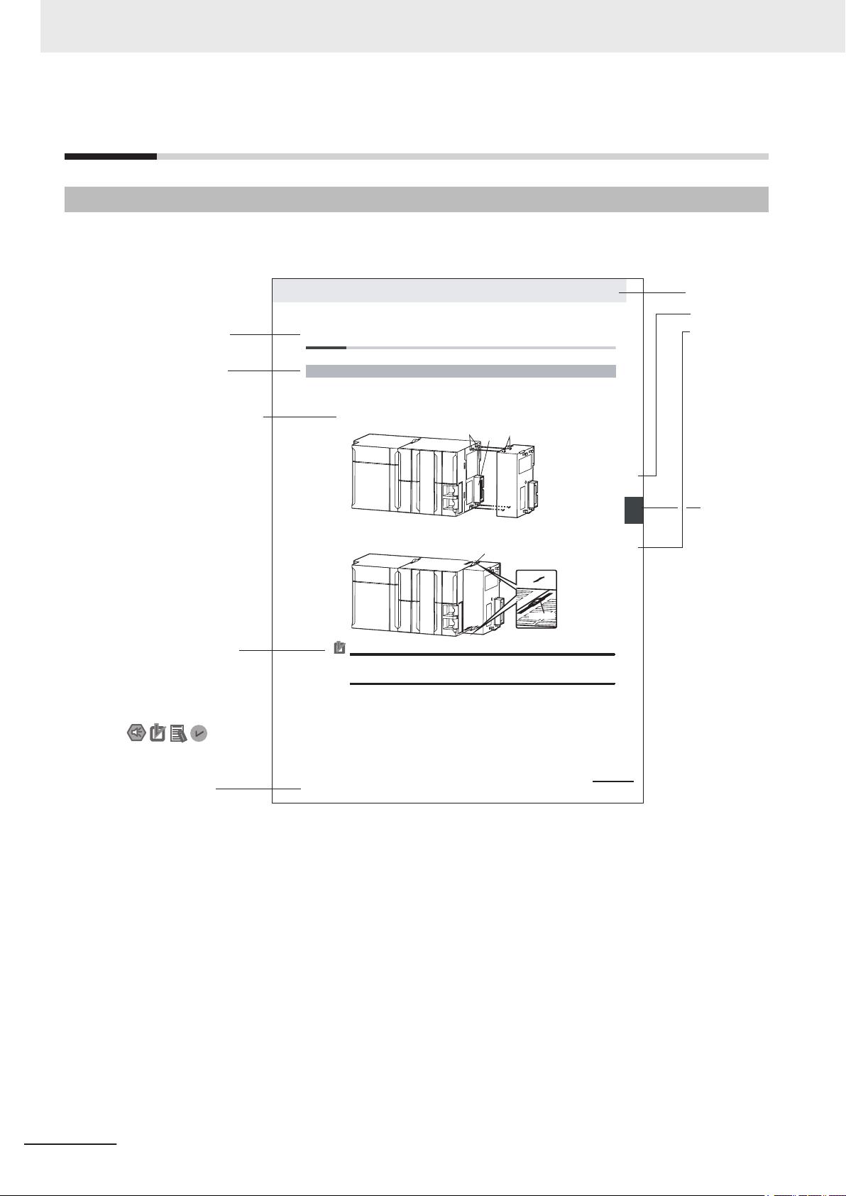
Manual Structure
Manual Structure
Page Structure
The following page structure is used in this manual.
Note This illustration is provided only as a sample. It may not literally appear in this manual.
2
CK3M-series Programmable Multi-Axis Controller User's Manual Hardware (O036)
Page 5

Special Information
Special information in this manual is classified as follows:
Precautions for Safe Use
Precautions on what to do and what not to do to ensure safe usage of the product.
Precautions for Correct Use
Precautions on what to do and what not to do to ensure correct operation and performance.
Additional Information
Additional information to read as required.
This information is provided to increase understanding and make operation easier
Manual Structure
.
CK3M-series Programmable Multi-Axis Controller User's Manual Hardware (O036)
3
Page 6

Manual Structure
4
CK3M-series Programmable Multi-Axis Controller User's Manual Hardware (O036)
Page 7

Sections in this Manual
1
2
3
4
5
1
2
3
4
5
A
Introduction to Motion Controllers
System Configuration
Configuration Units
Installation
W
iring
A
6
7
Appendices
6
7
Troubleshooting
Inspection and Maintenance
I
I
Index
Sections in this Manual
CK3M-series Programmable Multi-Axis Controller User's Manual Hardware (O036)
5
Page 8

CONTENTS
CONTENTS
Introduction .............................................................................................................. 1
Intended Audience
Applicable Products ......................................................................................................................................... 1
Manual Structure...................................................................................................... 2
Page Structure.................................................................................................................................................2
Special Information .......................................................................................................................................... 3
Sections in this Manual ........................................................................................... 5
Terms and Conditions Agreement........................................................................ 10
Warranty, Limitations of Liability ....................................................................................................................10
Application Considerations ............................................................................................................................11
Disclaimers ....................................................................................................................................................11
Safety Precautions................................................................................................. 13
Definition of Precautionary Information.......................................................................................................... 13
Symbols ......................................................................................................................................................... 13
WARNING......................................................................................................................................................14
Cautions.........................................................................................................................................................16
...........................................................................................................................................1
Precautions for Safe Use ...................................................................................... 17
Precautions for Correct Use ................................................................................. 22
Regulations and Standards .................................................................................. 24
Conformance to EU Directives ......................................................................................................................24
Condition for Compliance with EU Directives ................................................................................................25
Conformance to UL and CSA Standards.......................................................................................................25
Conformance to KC Certification ...................................................................................................................25
Versions.................................................................................................................. 26
Checking Versions.........................................................................................................................................26
Related Manuals..................................................................................................... 27
Terminology............................................................................................................ 28
Revision History..................................................................................................... 29
Section 1 Introduction to Motion Controllers
1-1 Features and System Configuration ....................................................................................1-2
1-1-1
1-1-2 Introduction to the System Configurations ..................................................................................1-2
1-1-3 Support Software ........................................................................................................................1-4
1-2 CK3M-series Operating Procedure ......................................................................................1-5
Motion Controller Features..........................................................................................................1-2
Section 2 System Configuration
2-1 Basic Configuration...............................................................................................................2-2
6
CK3M-series Programmable Multi-Axis Controller User's Manual Hardware (O036)
Page 9

2-1-1 CK3W Unit Configuration ............................................................................................................2-2
2-1-2
EtherCAT Network Configuration................................................................................................2-3
2-2 Connecting to the Power PMAC IDE .................................................................................... 2-5
2-3 Ethernet Network Configuration...........................................................................................2-6
Section 3 Configuration Units
3-1 CPU Unit .................................................................................................................................3-3
3-1-1
3-1-2 Part Names and Functions..........................................................................................................3-5
3-1-3 Operation Status Indicators.........................................................................................................3-6
3-1-4 Watchdog Output Terminal Block................................................................................................3-7
3-1-5 USB Memory Device...................................................................................................................3-8
3-2 Power Supply Unit ...............................................................................................................3-10
3-2-1 Models and Specifications ........................................................................................................3-10
3-2-2 Part Names and Functions........................................................................................................ 3-11
3-3 Axis Interface Unit ...............................................................................................................3-12
3-3-1 Models and Specifications ........................................................................................................3-12
3-3-2 Part Names and Functions........................................................................................................3-14
3-3-3 Operation Status Indicators.......................................................................................................3-15
3-3-4 Address Switch Setting .............................................................................................................3-16
3-3-5 Encoder Connector Specifications ............................................................................................3-16
3-3-6 Encoder Loss Detection ............................................................................................................3-21
3-3-7 Pulse Input Timing Specifications for Digital Quadrature Encoder............................................3-22
3-3-8 Input Specifications for Sinusoidal Encoder..............................................................................3-24
3-3-9 OutFlag Function.......................................................................................................................3-26
3-3-10 Amplifier Connector Specifications ...........................................................................................3-27
3-3-11 DA Output Method ....................................................................................................................3-30
3-3-12 DirectPWM Output Method .......................................................................................................3-31
3-3-13 Flag Connection Terminal Block Specifications ........................................................................3-32
3-3-14 General Digital I/O Connection Terminal Block Specifications..................................................3-36
3-4 Digital I/O Unit ......................................................................................................................3-43
3-4-1 Models and Specifications ........................................................................................................3-43
3-4-2 Part Names and Functions........................................................................................................3-47
3-4-3 Operation Indicators..................................................................................................................3-48
3-4-4 Address Switch Setting .............................................................................................................3-48
3-4-5 Terminal Arrangement...............................................................................................................3-49
3-4-6 I/O Data.....................................................................................................................................3-50
3-5 Analog Input Unit ................................................................................................................. 3-52
3-5-1 Models and Specifications ........................................................................................................3-52
3-5-2 Part Names and Functions........................................................................................................3-53
3-5-3 Operation Indicators..................................................................................................................3-54
3-5-4 Address Switch Setting .............................................................................................................3-54
3-5-5 Terminal Arrangement...............................................................................................................3-55
3-5-6 Analog Input Data .....................................................................................................................3-56
3-5-7 Input Filter .................................................................................................................................3-57
3-6 Expansion Master Unit and Expansion Slave Unit ...........................................................3-59
3-6-1 Models and Specifications ........................................................................................................3-59
3-6-2 Part Names and Functions........................................................................................................3-60
3-6-3 Operation Indicators..................................................................................................................3-60
3-6-4 System Configuration................................................................................................................3-60
Models and Specifications ..........................................................................................................3-3
CONTENTS
Section 4 Installation
4-1 Processing at Power ON and Power OFF............................................................................4-2
4-1-1
4-1-2 Power OFF Operation .................................................................................................................4-2
CK3M-series Programmable Multi-Axis Controller User's Manual Hardware (O036)
Power ON Operation...................................................................................................................4-2
7
Page 10

CONTENTS
4-2 Fail-safe Circuits .................................................................................................................... 4-4
4-3
Mounting Units.......................................................................................................................4-5
4-3-1 Installation in a Control Panel .....................................................................................................4-5
4-3-2 Connecting Adjacent Units..........................................................................................................4-9
4-3-3 Mounting to DIN Track ..............................................................................................................4-10
4-3-4 DIN Track and Accessories.......................................................................................................4-12
4-3-5 Assembled Appearance and Dimensions .................................................................................4-13
4-4 Control Panel Installation....................................................................................................4-17
4-4-1 Temperature ..............................................................................................................................4-17
4-4-2 Humidity ....................................................................................................................................4-18
4-4-3 Vibration and Shock ..................................................................................................................4-19
4-4-4 Atmosphere...............................................................................................................................4-19
4-4-5 Electrical Environment ..............................................................................................................4-19
4-4-6 Grounding .................................................................................................................................4-24
Section 5 Wiring
5-1 Power Supply Wiring ............................................................................................................. 5-2
5-1-1
5-1-2 Power Supply Used.....................................................................................................................5-2
5-1-3 Applicable Wires .........................................................................................................................5-2
5-1-4 Grounding ...................................................................................................................................5-3
5-1-5 Required Tools ............................................................................................................................5-4
5-1-6 Connecting Ferrules....................................................................................................................5-4
5-1-7 Connecting Twisted Wires/Solid Wires .......................................................................................5-4
5-1-8 Removing Wires..........................................................................................................................5-5
5-2 CPU Unit Wiring .....................................................................................................................5-7
5-2-1 Laying the EtherCAT Network .....................................................................................................5-7
5-2-2 Laying the Ethernet Network.....................................................................................................5-12
5-2-3 Watchdog Timer Output Wiring .................................................................................................5-15
5-2-4 USB Memory Device Connection..............................................................................................5-17
5-3 Axis Interface Unit Wiring ...................................................................................................5-18
5-3-1 Encoder Connector Wiring ........................................................................................................5-18
5-3-2 Amplifier Connector Wiring .......................................................................................................5-24
5-3-3 Flag Terminal Block/General I/O Terminal Block Wiring............................................................5-26
5-4 Digital I/O Unit Wiring .......................................................................................................... 5-33
5-4-1 Wiring the Terminals..................................................................................................................5-33
5-4-2 Precautions When Connecting a Two-wire DC Sensor.............................................................5-36
5-4-3 Precautions When Connecting to Digital Output.......................................................................5-38
5-5 Analog Input Unit Wiring.....................................................................................................5-40
5-5-1 Wiring the Terminals..................................................................................................................5-40
5-6 Expansion Master Unit and Expansion Slave Unit Wiring ............................................... 5-44
Power Supply Unit CK3W-PD048 ...............................................................................................5-2
Section 6 Troubleshooting
6-1 Types of Errors.......................................................................................................................6-2
6-2
Using the Indicators to Check Errors ..................................................................................6-3
6-2-1 Indicator Types............................................................................................................................6-3
6-2-2 Procedure for Identifying Errors ..................................................................................................6-3
6-3 Troubleshooting for Errors ................................................................................................... 6-5
6-3-1 Fatal Errors in the CPU Unit........................................................................................................6-5
6-3-2 Non-fatal errors in the CPU Unit .................................................................................................6-6
6-3-3 Initialization of CPU Unit Using USB Memory.............................................................................6-8
6-4 Sys.Status Register ...............................................................................................................6-9
6-4-1 Sys.Status Register List ..............................................................................................................6-9
6-4-2 Details of Flags ...........................................................................................................................6-9
8
CK3M-series Programmable Multi-Axis Controller User's Manual Hardware (O036)
Page 11

Section 7 Inspection and Maintenance
7-1 Cleaning and Maintenance....................................................................................................7-2
7-1-1
7-1-2 Periodic Inspections ....................................................................................................................7-2
7-2 Maintenance Procedures ......................................................................................................7-4
7-2-1 Unit Replacement Precautions....................................................................................................7-4
7-2-2 Backup ........................................................................................................................................7-4
7-2-3 Unit Replacement........................................................................................................................7-4
Cleaning ......................................................................................................................................7-2
Appendices
A-1 General Specifications ......................................................................................................... A-2
A-2
Dimensions............................................................................................................................ A-3
A-2-1 CPU Unit .................................................................................................................................... A-3
A-2-2 Power Supply Unit...................................................................................................................... A-4
A-2-3 Axis Interface Unit ...................................................................................................................... A-4
A-2-4 CK3W-MD and CK3W-AD Units ................................................................................................ A-5
A-2-5 Expansion Master Unit and Expansion Slave Unit..................................................................... A-6
A-2-6 End Cover .................................................................................................................................. A-7
A-3 Restrictions on Using the NX-series EtherCAT Coupler Unit........................................... A-8
A-4 OMRON Servo Drive Connection Example......................................................................... A-9
A-5 Version Information ............................................................................................................ A-10
A-6 How to Read the Lot Number............................................................................................. A-11
CONTENTS
Index
CK3M-series Programmable Multi-Axis Controller User's Manual Hardware (O036)
9
Page 12

Terms and Conditions Agreement
Terms and Conditions Agreement
Warranty, Limitations of Liability
Warranties
Exclusive Warranty
Omron’s exclusive warranty is that the Products will be free from defects in materials and workmanship for a period of twelve months from the date of sale by Omron (or such other period expressed in writing by Omron). Omron disclaims all other warranties, express or implied.
Limitations
OMRON MAKES NO WARRANTY OR REPRESENTATION, EXPRESS OR IMPLIED, ABOUT
NON-INFRINGEMENT, MERCHANTABILITY OR FITNESS FOR A PARTICULAR PURPOSE OF
THE PRODUCTS. BUYER ACKNOWLEDGES THAT IT ALONE HAS DETERMINED THAT THE
PRODUCTS WILL SUITABLY MEET THE REQUIREMENTS OF THEIR INTENDED USE.
Omron further disclaims all warranties and responsibility of any type for claims or expenses based
on infringement by the Products or otherwise of any intellectual property right.
Buyer Remedy
Omron’s sole obligation hereunder shall be, at Omron’s election, to (i) replace (in the form originally
shipped with Buyer responsible for labor charges for removal or replacement thereof) the non-complying Product, (ii) repair the non-complying Product, or (iii) repay or credit Buyer an amount equal
to the purchase price of the non-complying Product; provided that in no event shall Omron be responsible for warranty, repair, indemnity or any other claims or expenses regarding the Products
unless Omron’s analysis confirms that the Products were properly handled, stored, installed and
maintained and not subject to contamination, abuse, misuse or inappropriate modification. Return
of any Products by Buyer must be approved in writing by Omron before shipment. Omron Companies shall not be liable for the suitability or unsuitability or the results from the use of Products in
combination with any electrical or electronic components, circuits, system assemblies or any other
materials or substances or environments. Any advice, recommendations or information given orally
or in writing, are not to be construed as an amendment or addition to the above warranty.
10
See http://www.omron.com/global/ or contact your Omron representative for published information.
Limitation on Liability; Etc
OMRON COMPANIES SHALL NOT BE LIABLE FOR SPECIAL, INDIRECT, INCIDENTAL, OR CONSEQUENTIAL DAMAGES, LOSS OF PROFITS OR PRODUCTION OR COMMERCIAL LOSS IN ANY
CK3M-series Programmable Multi-Axis Controller User's Manual Hardware (O036)
Page 13

WAY CONNECTED WITH THE PRODUCTS, WHETHER SUCH CLAIM IS BASED IN CONTRACT,
W
ARRANTY, NEGLIGENCE OR STRICT LIABILITY.
Further, in no event shall liability of Omron Companies exceed the individual price of the Product on
which liability is asserted.
Application Considerations
Suitability of Use
Omron Companies shall not be responsible for conformity with any standards, codes or regulations
which apply to the combination of the Product in the Buyer
er’s request, Omron will provide applicable third party certification documents identifying ratings and
limitations of use which apply to the Product. This information by itself is not sufficient for a complete
determination of the suitability of the Product in combination with the end product, machine, system, or
other application or use. Buyer shall be solely responsible for determining appropriateness of the particular Product with respect to Buyer’s application, product or system. Buyer shall take application responsibility in all cases.
Terms and Conditions Agreement
’s application or use of the Product. At Buy-
NEVER USE THE PRODUCT FOR AN APPLICATION INVOLVING SERIOUS RISK TO LIFE OR
PROPERTY OR IN LARGE QUANTITIES WITHOUT ENSURING THAT THE SYSTEM AS A WHOLE
HAS BEEN DESIGNED TO ADDRESS THE RISKS, AND THAT THE OMRON PRODUCT(S) IS
PROPERLY RATED AND INSTALLED FOR THE INTENDED USE WITHIN THE OVERALL EQUIPMENT OR SYSTEM.
Programmable Products
Omron Companies shall not be responsible for the user’s programming of a programmable Product, or
any consequence thereof.
Disclaimers
Performance Data
Data presented in Omron Company websites, catalogs and other materials is provided as a guide for
the user in determining suitability and does not constitute a warranty
Omron’s test conditions, and the user must correlate it to actual application requirements. Actual performance is subject to the Omron’s Warranty and Limitations of Liability.
. It may represent the result of
Change in Specifications
Product specifications and accessories may be changed at any time based on improvements and other reasons. It is our practice to change part numbers when published ratings or features are changed,
or when significant construction changes are made. However
CK3M-series Programmable Multi-Axis Controller User's Manual Hardware (O036)
, some specifications of the Product may
11
Page 14

Terms and Conditions Agreement
be changed without any notice. When in doubt, special part numbers may be assigned to fix or establish key specifications for your application. Please consult with your Omron’
time to confirm actual specifications of purchased Product.
Errors and Omissions
Information presented by Omron Companies has been checked and is believed to be accurate; however
, no responsibility is assumed for clerical, typographical or proofreading errors or omissions.
s representative at any
12
CK3M-series Programmable Multi-Axis Controller User's Manual Hardware (O036)
Page 15
Safety Precautions
Indicates a potentially hazardous situation which, if
not avoided, could result in death or serious injury.
Additionally, there may be severe property
damage.
Indicates a potentially hazardous situation which, if
not avoided, may result in minor or moderate
injury, or property damage.
WARNING
C
aution
Definition of Precautionary Information
The following notation is used in this manual to provide precautions required to ensure safe usage of
the CK3M-series Programmable Multi-Axis Controller.
The safety precautions that are provided are extremely important for safety. Always read and heed the
information provided in all safety precautions.
The following notation is used.
Safety Precautions
Symbols
The circle and slash symbol indicates operations that you must not do.
The specific operation is shown in the
This example indicates that disassembly is prohibited.
The triangle symbol indicates precautions (including warnings).
The specific operation is shown in the
This example indicates a precaution for electric shock.
The triangle symbol indicates precautions (including warnings).
The specific operation is shown in the
This example indicates a general precaution.
The filled circle symbol indicates operations that you must do.
The specific operation is shown in the
This example shows a general precaution for something that you must do.
circle and explained in text.
triangle and explained in text.
triangle and explained in text.
circle and explained in text.
CK3M-series Programmable Multi-Axis Controller User's Manual Hardware (O036)
13
Page 16
WARNING
Internal
power
supply
circuit
(Non-isolat-
ed)
Power Supply Unit
Cable
External device
External power supply
Power supply
connection
terminal block
Non-isolated DC
power supply
CK3W Unit
+
-
Safety Precautions
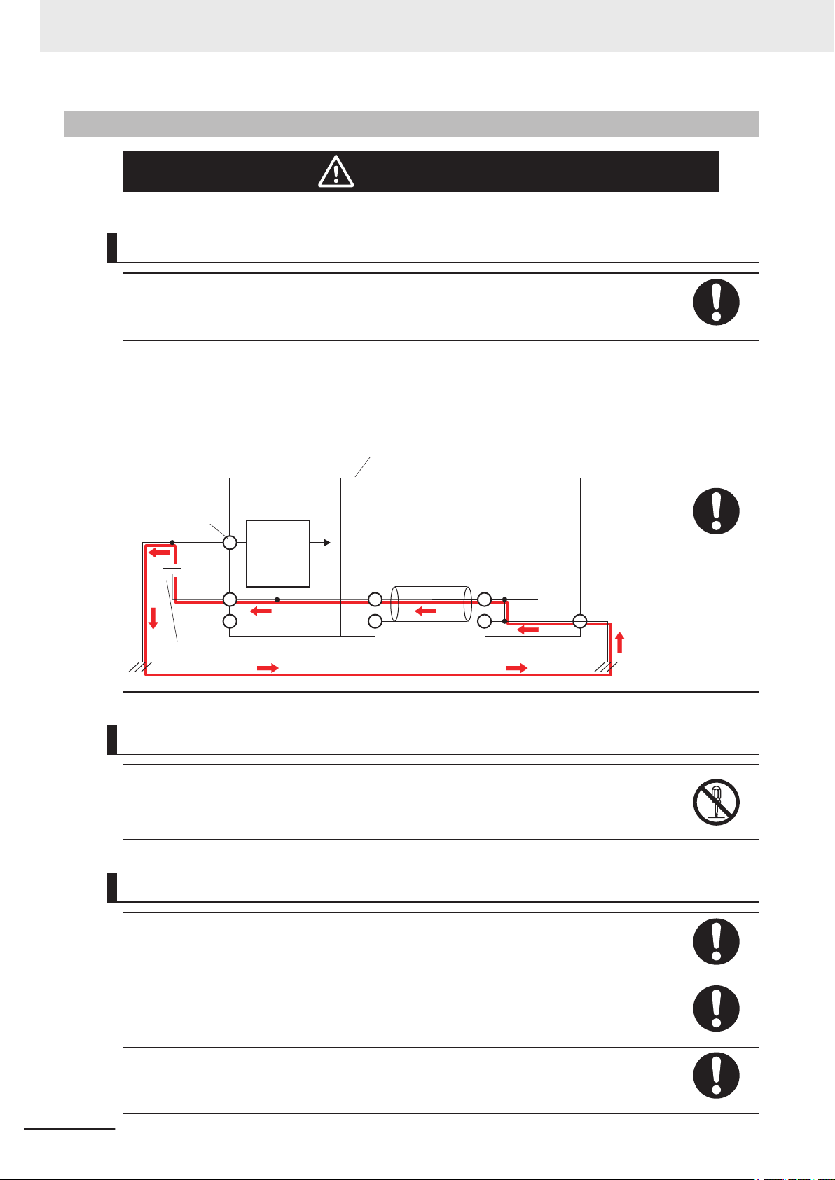
WARNING
Wiring
Connect this Controller correctly to the servo amplifier, encoder, and limit sensors according to the instructions in this manual. Not doing so may cause the motor to run
away
, resulting in serious accidents.
For the Power Supply Unit or any other power supply connected to peripheral devices,
connect the 0-V side to ground, or do not ground them at all.
Depending on how devices connected to the non-insulated circuit are grounded, the
power supply may be short-circuited.
Never ground the 24-V side of the power supply
, as shown in the following figure.
14
During Power Supply
Do not attempt to take any Unit apart.
In particular
, high-voltage parts are present in the Power Supply Unit while power is
supplied or immediately after power is turned OFF. Touching any of these parts may
result in electric shock. There are sharp parts inside the Unit that may cause injury.
Fail-safe Measures
Provide safety measures in external circuits to ensure safety in the system if an abnormality occurs due to malfunction of the products or due to other external factors af
ing operation. Not doing so may result in serious accidents due to incorrect operation.
Emergency stop circuits, interlock circuits, limit circuits, and similar safety measures
must be provided in external control circuits.
You must take fail-safe measures to ensure safety in the event of incorrect, missing, or
abnormal signals caused by broken signal lines, momentary power interruptions, or
other causes.
CK3M-series Programmable Multi-Axis Controller User's Manual Hardware (O036)
fect-
Page 17

Safety Precautions
The UPS used enables normal operation to continue for a certain period of time if a
momentary power interruption occurs. This means that the CK3M-series Controller
may receive incorrect signals from external devices that are also af
interruption. Accordingly, take suitable actions, such as establishing external fail-safe
measures and interlock conditions, to monitor the power supply voltage of the external
device as required.
Unintended outputs may occur if an error occurs in internal data of the Controller. As a
countermeasure for these problems, external safety measures must be provided to ensure safe operation of the system.
The Controller will turn OFF all outputs of output units in the following cases and the
slaves will operate according to the settings in the slaves.
•
If a power supply error occurs
• If the connected power supply is faulty
• If a CPU Unit error (watchdog timer error) or CPU Unit reset occurs
• If a major fault level Controller error occurs
• While the Controller is on standby until RUN mode is entered after the power is
turned ON
• If a system initialization error occurs
External safety measures must be provided to ensure safe operation of the system in
such cases.
The outputs may remain ON or OFF due to welding or burning of the output relays or
destruction of the output transistors. As a countermeasure for these problems, external
safety measures must be provided to ensure safe operation of the system.
fected by the power
To ensure safe use of the Controller, correctly make the limit settings for the position,
speed, acceleration, jerk, current, and following error
tection.
For devices that move in a vertical direction, use a motor brake to prevent them from
falling down when the servo control is stopped.
, as well as the encoder loss de-
Downloading
Always confirm safety at the destination before you transfer a user program, configuration data, or setup data from the Power PMAC IDE.
The devices or machines may perform unexpected operation regardless of the operating mode of the Controller
After you transfer the user program, the Controller is restarted and communications
with the EtherCA
cording to the slave specifications.
The time that communications are cut off depends on the EtherCAT network configuration.
Before you transfer the user program, confirm that the system will not be adversely affected.
T slaves are cut off. During that period, the slave outputs behave ac-
.
Test Run
Before you start a Test Run, make sure that the operation parameters are set correctly.
CK3M-series Programmable Multi-Axis Controller User's Manual Hardware (O036)
15
Page 18

Caution
Safety Precautions
Actual Operation
Check the user program, servo algorithm, data, and parameter settings for proper execution before you use them for actual operation.
Cautions
Design
To control the motor safely and correctly, the servo algorithm design and gain setting
work must be performed by engineers who understand control theories and the specifications of this product.
Test Run
When you perform a test run, take fail-safe measures and run the motor at a sufficiently low speed to ensure safety
.
Downloading
Before you download a project written in C language, execute the re-initialization command ($$$***).
If you download a validated program to a different product, check the operation of the
program again on the product because it may have dif
ferent settings.
16
CK3M-series Programmable Multi-Axis Controller User's Manual Hardware (O036)
Page 19

Precautions for Safe Use
Transporting
• Do not drop any Unit or subject it to abnormal vibration or shock. Doing so may result in Unit malfunction or burning.
Mounting
• Be sure that the terminal blocks, connectors, and other items with locking devices are correctly
locked into place before use.
• When connecting the Power Supply Unit, CPU Unit, and CK3W Unit, connect the Units together,
then slide the sliders on the top and bottom until they click into place, and lock securely.
• Always mount an end cover for use. Note that if an end cover is not mounted, the Unit may not function satisfactorily.
• The number of CK3W Units connected to the CPU Unit must be within the specified range.
Precautions for Safe Use
Installation
• Always connect to a ground of 100 Ω or less when installing the Units.
• For DIN Track installation, correctly follow the instructions in this manual.
Wiring
• Follow the instructions in this manual to correctly perform terminal block and connector wiring and
insertion.
Double-check all wiring and connector insertion before turning ON the power supply.
• If the external power supply to a digital output or a slave has polarity, connect it with the correct polarity.
If the polarity is reversed, current may flow in the reverse direction and damage the connected devices regardless of the operation of the Controller.
• Before you connect a computer to the Controller, disconnect the power supply plug of the computer
from the AC outlet.
Also, if the computer has an FG terminal, connect it such that the FG terminal has the same electrical potential as the FG on the product.
A difference in electrical potential between the computer and the Controller may cause a failure or
malfunction.
• Do not pull on the cables or bend the cables beyond their natural limit.
• Do not place heavy objects on top of the cables or other wiring lines. Doing so may break the cables.
• Always use power supply wires with sufficient wire diameters to prevent voltage drop and burning.
Make sure that the current capacity of the wire is sufficient. Otherwise, excessive heat may be generated.
CK3M-series Programmable Multi-Axis Controller User's Manual Hardware (O036)
17
Page 20

Precautions for Safe Use
When cross-wiring terminals, the total current for all the terminals will flow in the wire. When wiring
cross-overs, make sure that the current capacity of each of the wires is not exceeded.
•
Do not allow wire clippings, shavings, or other foreign material to enter the Controller. Otherwise,
Controller burning, failure, or malfunctions may occur.
Cover the Controller or take other suitable countermeasures, in particular when carrying out wiring
work.
• To ensure safe use of the functions of the CK3W Units, observe the following points when wiring to
avoid the effects of the noise.
a) Use twisted-pair shielded wire for the encoder connection lines, amplifier connection lines, and
analog input lines.
b) Wire the encoder connection lines, amplifier connection lines, and analog input lines separately
from the AC power lines, motor power lines, and other power lines, and do not insert into the
same duct.
c) If there are noise effects from power supply lines when using the same power supply to power
an electrical welder or an electric discharge machine, or there is a high-frequency source nearby,
insert a noise filter into the power supply input section.
Power Supply Design
• In the system, only use a power supply within the rated supply capacity range specified in this manual.
•
Install external breakers and take other safety measures against short-circuiting and overcurrents in
external wiring.
• Do not apply voltages to the Input Units in excess of the rated input voltage.
• Do not apply voltages or connect loads to the Output Units in excess of the maximum switching capacity.
Turning ON the Power Supply
• It takes approximately several tens of seconds to enter RUN mode after the power supply is turned
ON. During that time, outputs will be OFF or the values will be as according to settings in the Unit or
slaves. Also, external communications will not be able to be performed. Implement fail-safe circuits
so that external devices do not operate incorrectly
• Surge current occurs when the power supply is turned ON. When selecting fuses or breakers for
external circuits, consider the above precaution and allow sufficient margin in shut-off performance.
Refer to this user's manual for surge current specifications.
• Configure the external circuits so that the power supply to the digital output turns ON only after the
power supply to the Controller has turned ON.
If the power supply to the Controller is turned ON after the digital output power supply, the digital
output may suddenly malfunction when the power supply is turned ON to the Controller.
.
18
Actual Operation
• Build a program such that the Sys.Status flag is constantly monitored and safe operations are taken
if any errors occur
.
CK3M-series Programmable Multi-Axis Controller User's Manual Hardware (O036)
Page 21

Precautions for Safe Use
Turning OFF the Power Supply
• Do not turn OFF the power supply or remove the USB memory device while the Controller is accessing the USB memory device. Data may become corrupted, and the Controller will not operate
correctly if it uses corrupted data.
•
Always turn OFF the power supply before you attempt any of the following.
a) Mounting or removing the Units
b) Assembling the Units
c) Setting rotary switches
d) Connecting cables or wiring the system
e) Connecting or disconnecting the terminal blocks or connectors
• Do not disconnect the cable or turn OFF the power supply to the product when downloading data or
programs from the Support Software. You may be unable to download the correct data, which could
result in malfunctions.
• Do not turn OFF the power supply when performing write processes to the built-in flash memory.
Data may be corrupted, which could result in malfunctions.
Operation
Confirm that no adverse effects will occur in the system before you attempt any of the following.
•
Changing the operating mode of the Controller (including changing operation mode setting when
power is turned ON)
• Changing the user program or settings
• Changing set values or present values
EtherCAT Communications
• Make sure that the communications distance, number of nodes connected, and method of connection for EtherCA
Do not connect EtherCAT communication to EtherNet/IP, a standard in-house LAN, or other networks. An overload may cause the network to fail or malfunction.
• If the Fail-soft Operation Setting parameter is set to Stop, process data communications will stop
for all the slaves when an EtherCAT communications error is detected in a slave. This means that if
a Servo Drive is connected, the Servo turns OFF for all the axes. At that time, the Servo Drive will
operate according to the Servo Drive specifications. Make sure that the fail-soft operation setting results in safe operation when a device error occurs.
• If noise occurs or an EtherCAT slave is disconnected from the network, any current communications
frames may be lost. If frames are lost, slave I/O data is not communicated, and unintended operation may occur. The slave outputs will behave according to the slave specifications. For details, refer
to the manual for the slave.
• When an EtherCAT slave is disconnected or disabled, communications will stop and control of the
outputs will be lost not only for the disconnected slave, but for all slaves connected after it. Confirm
that the system will not be adversely affected before you disconnect or disable a slave.
• You cannot use standard Ethernet hubs or repeater hubs with EtherCAT communications. If you use
one of these, a major fault level error or other error may occur.
T are within specifications.
CK3M-series Programmable Multi-Axis Controller User's Manual Hardware (O036)
19
Page 22

Precautions for Safe Use
• EtherCAT communications are not always established immediately after the power supply is turned
ON. Use the system-defined variables and the EtherCA
program to confirm that I/O data communications are established before attempting control operations.
• If you need to disconnect the cable from an EtherCAT slave during operation, first reset the EtherCAT and EtherCAT slaves that are connected after it to the Init state, then disconnect the EtherCAT
slave.
• For EtherCAT and EtherNet, use the connection methods and cables that are specified in this manual. Otherwise, communications may be faulty.
• Make sure that all of the slaves to be restored are participating in the network before you reset the
EtherCAT Master Function Module. If any slave is not participating in the network when any of these
errors is reset, the EtherCAT Master Function Module may access a slave with a different node address than the specified node address, or the error may not be reset correctly.
• There is a time lag between the moment when this Controller sends a command value to the EtherCAT type Servo Drive and the moment when it receives the feedback value. Perform servo control
taking this time lag into consideration.
T Coupler Unit device variables in the user
Motion Control
• The motor is stopped if communications are interrupted between the Power PMAC IDE and the
Controller during a T
tem will not be adversely affected before you perform a Test Run.
• EtherCAT communications are not always established immediately after the power supply is turned
ON. Use the system-defined variables in the user program to confirm that communications are established before attempting control operations.
• When you create a servo algorithm, take fail-safe measures in the user program which includes the
servo algorithm.
est Run. Connect the communications cable securely and confirm that the sys-
Unit Replacement
• Make sure that the required data, including the user program, configurations, settings, and variables, is transferred to the Controller that was replaced and to externally connected devices before
restarting operation.
Upgrading the Power PMAC IDE
20
• After you upgrade a project file created with an older version of the Power PMAC IDE for use with a
newer version of Power PMAC IDE, perform a test run before use to check that the project file was
upgraded correctly
.
Maintenance
• Do not attempt to disassemble, repair, or modify the Controller. Doing so may result in a malfunction
or fire.
CK3M-series Programmable Multi-Axis Controller User's Manual Hardware (O036)
Page 23

Precautions for Safe Use
• Do not use corrosive chemicals to clean the Controller. Doing so may result in a failure or malfunction of the Controller
• Dispose of the product according to local ordinances as they apply.
.
CK3M-series Programmable Multi-Axis Controller User's Manual Hardware (O036)
21
Page 24

Precautions for Correct Use
Precautions for Correct Use
Storage and Installation
• Follow the instructions in this manual to correctly perform installation.
• Do not operate or store the Controller in the following locations. Doing so may result in burning, in
operation stopping, or in malfunction.
a) Locations subject to direct sunlight
b) Locations subject to temperatures or humidity outside the range specified in the specifications
c) Locations subject to condensation as the result of severe changes in temperature
d) Locations subject to corrosive or flammable gases
e) Locations subject to dust (especially iron dust) or salts
f) Locations subject to exposure to water, oil, or chemicals
g) Locations subject to shock or vibration
• Take appropriate and sufficient countermeasures when installing the Controller in the following locations.
a) Locations subject to strong, high-frequency noise
b) Locations subject to static electricity or other forms of noise
c) Locations subject to strong electromagnetic fields
d) Locations subject to possible exposure to radioactivity
e) Locations close to power lines
• Before touching a Unit, be sure to first touch a grounded metallic object in order to discharge any
static build-up.
• Install the Controller away from sources of heat and ensure proper ventilation. Not doing so may result in malfunction, in operation stopping, or in burning.
Wiring
• Use the rated power supply voltage for the products.
Task Settings
• If a Task Period Exceeded error occurs, shorten the programs to fit in the task period or increase the
setting of the task period.
During Operation
• Do not disconnect the communications cable while the system is running. Doing so may result in a
failure or malfunction of the system.
Motion Control
• Do not download motion control settings during a Test Run.
22
CK3M-series Programmable Multi-Axis Controller User's Manual Hardware (O036)
Page 25

Precautions for Correct Use
EtherCAT Communications
• Set the Servo Drives to stop operation if an error occurs in EtherCAT communications between the
Controller and a Servo Drive.
•
Always use the specified EtherCAT slave cables. If you use any other cable, the EtherCAT master
or the EtherCAT slaves may detect an error and one of the following may occur.
a) Continuous refreshing of process data communications will not be possible.
b) Continuous refreshing of process data communications will not end during the set cycle
USB Devices
• Always use USB memory devices that comply with the USB standards.
CK3M-series Programmable Multi-Axis Controller User's Manual Hardware (O036)
23
Page 26

Regulations and Standards
Regulations and Standards
Conformance to EU Directives
Applicable Directives
• EMC Directives
Concepts
EMC Directives
OMRON devices that comply with EU Directives also conform to the related EMC standards so that
they can be more easily built into other devices or the overall machine. The actual products have
been checked for conformity to EMC standards.*1
Whether the products conform to the standards in the system used by the customer, however, must
be checked by the customer. EMC-related performance of the OMRON devices that comply with
EU Directives will vary depending on the configuration, wiring, and other conditions of the equipment or control panel on which the OMRON devices are installed. The customer must, therefore,
perform the final check to confirm that devices and the overall machine conform to EMC standards.
*1. Applicable EMC (Electromagnetic Compatibility) standards are as follows: EMS (Electromagnetic Suscept-
ibility): EN61326 EMI (Electromagnetic Interference): EN61326 (Radiated emission: 10-m regulations).
Conformance to EU Directives
The CK3M-series Units comply with EU Directives. To ensure that the machine or device in which
the CK3M-series Units are used complies with EU Directives, the following precautions must be observed.
• The CK3M-series Units must be installed within a control panel.
• You must use double or reinforced insulation power supply for the DC power supplies that are
connected as the Unit power supplies for the CK3M-series Units.
We recommend that you use the OMRON S8VK-S series DC Power Supplies. EMC standard
compliance was confirmed for the recommended Power Supplies.
• The CK3M-series Units that comply with EU Directives also conform to the Common Emission
Standard (EN61326). Radiated emission characteristics (10-m regulations) may vary depending
on the configuration of the control panel used, other devices connected to the control panel, wiring, and other conditions.
You must therefore confirm that the overall machine or equipment in which the CK3M-series
Units are used complies with EU Directives.
• This is a Class A product (for industrial environments). In a residential environment, it may cause
radio interference. If radio interference occurs, the user may be required to take appropriate
measures.
24
CK3M-series Programmable Multi-Axis Controller User's Manual Hardware (O036)
Page 27
Condition for Compliance with EU Directives
The immunity test condition for the CK3M-series Analog Input Units is as shown below.
Unit type Overall accuracy
Analog Input Unit +6%/-6%
To connect an Analog Input Unit, use 2-core twisted-pair shielded wire. Note that compliance was confirmed with the shielded wire grounded at both ends.
Conformance to UL and CSA Standards
The CK3M-series Units comply with UL and CSA standards.
For how to make your machine or device compliant with these standards, refer to the INSTRUCTION
SHEET
The INSTRUCTION SHEET provides usage conditions to make it compliant with the standards.
included with the product.
Regulations and Standards
Conformance to KC Certification
When you use this product in South Korea, observe the following precautions.
This product meets the electromagnetic compatibility requirements for business use. There is a risk of
radio interference when this product is used in home.
CK3M-series Programmable Multi-Axis Controller User's Manual Hardware (O036)
25
Page 28
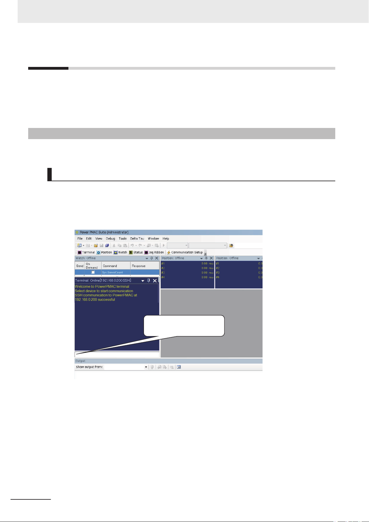
Enter “vers”
Versions
Versions
PMAC firmware revisions are used to manage the motion control firmware in CK3M-series CPU Units.
The PMAC firmware revision is updated each time there is a change in motion control firmware. Even
when two CPU Units have the same model number, they will have functional or performance differences if they have different PMAC firmware revisions.
Checking Versions
You can check the PMAC firmware revision in Power PMAC IDE.
Checking with Power PMAC IDE
1 Connect the CK3M-series CPU Unit and Power PMAC IDE online.
2 Input vers to the terminal window
.
26
The firmware revision is displayed on the command line.
CK3M-series Programmable Multi-Axis Controller User's Manual Hardware (O036)
Page 29

Related Manuals
The following manuals are related. Use these manuals for reference. Contact your OMRON representative for information on how to procure these manuals.
Manual name Cat. No. Application Description
CK3M-series Programmable Multi-Axis Controller
Hardware User
Power PMAC User’s Manual
Power PMAC Software Reference Manual
Power PMAC IDE User
Manual
Power PMAC-NC-16 Quick
Start Manual
Power PMAC-NC16 .ini
Configuration Manual
Power PMAC-NC16 Software User Manual
Power PMAC-NC16 Mill GCode Manual
’s Manual
O036 Learning the basic
O014 Learning the features
O015 Learning how to pro-
O016 Learning how to oper-
O017 Briefly understanding
O018 Configuring an appli-
O019 Learning about usage
O020 Creating programs for
specifications of the
CK3M-series Programmable Multi-Axis
Controller, including
introductory information, design, installation, and maintenance.
Mainly hardware information is provided.
and usage examples
of the
CK3M-series
Programmable MultiAxis Controller.
gram a CK3M-series
Programmable MultiAxis Controller
ate Power PMAC IDE,
the integrated development environment
of the Controller.
the basic usage of
Power PMAC-NC16.
cation for CNC devices by using Power
PMAC-NC16.
and features of Power
PMAC-NC16, Support
Software required to
use the Controller for
CNC devices.
CNC devices by using
Power PMAC-NC16.
.
Related Manuals
An introduction to the entire CK3M-series system
is provided along with the following information.
• Features and system configuration
• Introduction
• Part names and functions
• General specifications
• Installation and wiring
• Maintenance and inspection
The following information is provided on the
CK3M-series Programmable Multi-Axis Controller.
• Basic functions
• Setup examples
• Programming examples
The following information is provided on the
CK3M-series Programmable Multi-Axis Controller.
• Details of commands
• Details of data structure
Describes the operating procedures of Power
PMAC IDE, and examples of how to start the system.
Describes the Quick setup procedure to run Power
PMAC-NC16 on a desktop PC by showing some
examples.
Describes how to set up PowerPmacNC.ini, the
setup data file to be loaded when Power PMACNC16 starts.
The following information is provided on Power
PMAC-NC16.
• How to use the software
• Features included in the software
• Features that can be customized
Describes the basic G-code set that can be used
for Power PMAC-NC16, and relevant instructions.
CK3M-series Programmable Multi-Axis Controller User's Manual Hardware (O036)
27
Page 30

Terminology
Terminology
Term Description
PMAC The acronym for Programmable Multi-Axis Controller.
Motion control Motion control can achieve intended operation by providing a target value to the axis to be con-
trolled, or by controlling state transitions.
Axis A functional unit within the Motion Control Function Module. An axis is assigned to the drive
mechanism in an external Servo Drive, etc.
NC The acronym for Computerized Numerical Control.
A method to numerically control machining processes in production by using computers. CNC has
been further automatized over conventional numerical control machine tools (NC machine tools).
G-code A type of language used to create NC programs.
CPU Central Processing Unit. Hardware that executes instructions from computer programs.
MODBUS/TCP A protocol used for the Modbus communications on TCP/IP.
EtherCAT The acronym for Ethernet for Control Automation Technology.
EtherCA
ENI file ENI is the acronym for EtherCAT Network Information.
The ENI file contains the network configuration information related to EtherCA
ESI file ESI is the acronym for EtherCAT Slave Information.
The ESI file contains information unique to the EtherCA
PMAC3 Style
DSPGate3 IC
Gate3 index IC index for PMAC3 Style DSPGate3 IC.
DirectPWM A Servo Drive interface unique to Delta Tau Data Systems, Inc.
FilteredPWM Method for creating analog output by smoothing the PWM pulse.
TrueDAC Method for creating analog output using a DA converter.
Serial encoder An encoder that uses communications to perform data transfer.
Digital quadrature encoder
Sinusoidal encoder A type of encoder that outputs SIN/COS waveforms at 1 Vpp.
Encoder loss detection function
Hall sensor A sensor that detects the rotor position of the motor by detecting the magnetic field.
Motion control IC developed by the U.S. company Delta Tau Data Systems, Inc.
Gate3 index is set with the DIP switch of the Unit.
If index is i, the CPU Unit accesses the CK3W Unit with Gate3[i] data structure.
A type of encoder that outputs pulse signals.
Function that detects if encoder is not connected.
T is the real-time Ethernet protocol standards.
T slaves.
T slaves in XML format.
28
CK3M-series Programmable Multi-Axis Controller User's Manual Hardware (O036)
Page 31

Revision History
O036-E1-02
Revi
sion code
A manual revision code appears as a suffix to the catalog number on the front and back covers of the
manual.
Revision History
Revision
code
01 July 2018 Original production
02 July 2019
Date Revised content
• Made changes accompanying the addition of CK3W
MD71£0/-AD£100/-EXM01/-EXS02 Units.
• Corrected mistakes.
-AX1313£/-AX2323£/-
CK3M-series Programmable Multi-Axis Controller User's Manual Hardware (O036)
29
Page 32

Revision History
30
CK3M-series Programmable Multi-Axis Controller User's Manual Hardware (O036)
Page 33

1
Introduction to Motion Controllers
This section describes the features, system configuration, and operating procedure of
a CK3M-series Programmable Multi-Axis Controller
1-1 Features and System Configuration ............................................................ 1-2
1-1-1 Motion Controller Features ............................................................................. 1-2
1-1-2 Introduction to the System Configurations...................................................... 1-2
1-1-3 Support Software ............................................................................................ 1-4
1-2 CK3M-series Operating Procedure............................................................... 1-5
.
1
CK3M-series Programmable Multi-Axis Controller User's Manual Hardware (O036)
1-1
Page 34

1 Introduction to Motion Controllers
1-1
1-1-1
Features and System Configuration
This section describes the features and basic system configuration of the CK3M-series Programmable
Multi-Axis Controller and Support Software.
Motion Controller Features
Fast Multi-Axis Control
The Motion Controller uses the Programmable Multi Axis Controller, developed by Delta Tau Data Systems, Inc. (hereinafter referred to as “Delta Tau”), a manufacturer specializing in motion controllers.
This enables control of a maximum of 16 axes of an analog input type or DirectPWM type Servo Drive
(when using four CK3W-AX£££££ Units and an Expansion Rack) at high speeds using the Axis
Interface Unit.
Constructing Systems with Greater Flexibility
Programs for the Motion Controller can be written in G-code, C language, or Programmable Multi-Axis
Controller specific language. This function design flexibility allows you to create functions that are optimized for your equipment.
arious EtherCAT-compatible products such as image sensors and I/O as well as motion controls can
V
be connected, allowing you to construct original systems to suit the equipment.
1-1-2
Compactness
The Controller is compact and has less wiring due to the use of the EtherCAT network, which helps to
downsize devices.
Introduction to the System Configurations
The Motion Controller supports the following system configurations.
The basic configurations include the CK3W Unit configuration, EtherCA
net network configuration, and Support Software.
T network configuration, Ether-
Basic Configuration
• CK3W Unit Configuration
Up to four CK3W Units (or up to two CK3W
Unit type Model
Axis Interface Unit
Digital I/O Unit
Analog Input Unit
CK3W-AX1313£/-AX1414£/-AX1515£/-AX2323£
CK3W-MD71£0
CK3W-AD£100
-AX Units) can be connected to the CPU Unit.
1-2
In addition to the CPU Rack, an Expansion Rack can be used to install additional CK3W Units.
CK3M-series Programmable Multi-Axis Controller User's Manual Hardware (O036)
Page 35

1 Introduction to Motion Controllers
You can add up to four CK3W Units (or up to two CK3W-AX Units) with the Expansion Rack.
1-1 Features and System Config-
By connecting an analog input type or DirectPWM type Servo Drive to a
CK3W-AX Unit, high-speed
axis control is enabled.
One CK3W-AX Unit controls up to four axes.
With the Expansion Rack, one CK3M-series CPU Unit can connect up to four CK3W-AX Units and
control a maximum of 16 axes in total.
A digital quadrature encoder, serial encoder, or sinusoidal encoder may be connected to the CK3WAX Units as encoder input for feedback. The CK3W-AX Units have general digital I/O with 16-point
input and 16-point output.
• EtherCAT Network Configuration
By using the EtherCAT master communications port on the CPU Unit, EtherCAT slaves such as servo drives, inverters, machine vision systems, digital and analog I/O, and other general-purpose
slaves can be connected.
The CPU Unit also supports connections with EtherCAT Slave Terminals. The EtherCAT Slave Terminal helps you to save space and construct flexible systems using a broad range of types of NX
Units.
However, when OMRON NX-series EtherCAT Coupler Units are used for the EtherCAT Slave Terminal, there are restrictions on the models and unit versions of EtherCAT Coupler Units that can be
connected.
Refer to A-3 Restrictions on Using the NX-series EtherCAT Coupler Unit on page A-8 for details.
uration
1
1-1-2 Introduction to the System Configurations
• Ethernet Network Configuration
The Ethernet communications port on the CPU Unit supports the Modbus-TCP protocol. It can be
connected to devices such as PLCs and programmable terminals that support the Modbus-TCP protocol.
• Support Software
Connect a computer with the Support Software installed to the Motion Controller via the Ethernet
network.
Refer to 1-1-3 Support Software on page 1-4 for details of the Support Software.
CK3M-series Programmable Multi-Axis Controller User's Manual Hardware (O036)
1-3
Page 36

Encoder (Digital quadrature encoder, serial encoder)
Servo drive (analog input type)
or Stepper motor
EtherCAT network
Support Software
PLC
Industrial
Ethernet
switch
Programmable
terminal
Ethernet
Networks
Modbus-TCP
Slave
terminal
Servo
drive/
Encoder
input
slaves
General-
purpose
slaves
1 Introduction to Motion Controllers
1-1-3
Support Software
The following table shows the Support Software used to configure, monitor, program, and debug the
Motion Controller
Configuration software Application How to Procure
Power PMAC IDE
Power
PMAC-NC16
*1. Refer to A-5 V
*2. Contact your OMRON representative for information on how to procure.
.
*1
Power
PMAC-NC16
SDK
Power
PMAC-NC16
Runtime
ersion Information on page A-10 for the supported Power PMAC IDE versions.
This computer software is used to configure
the Motion Controller
and debug the programs.
This computer software is used to control
working machines and other CNC machines
with the Motion Controller
to customize HMI screens. The product contains extension source codes for customization.
This computer software is used to control
working machines and other CNC machines
with the Motion Controller
when you do not customize HMI screens.
, create user programs,
. Use this software
. Use this software
This is free software.
*2
This is non-free software.
This is non-free software.
*2
*2
1-4
CK3M-series Programmable Multi-Axis Controller User's Manual Hardware (O036)
Page 37

1 Introduction to Motion Controllers
1-2 CK3M-series Operating Pro-
1-2
CK3M-series Operating Procedure
This section describes the procedure to construct a motion control system by using the CK3M-series
Programmable Multi-Axis Controller.
No. Step Description Reference
1 Preparation for
work
Check for specification compatibility
Check compatibility with specifications of
each Unit.
• General specifications
A-1 General Specifications on
A-2
page
• Mounting direction
2 Mounting and
wiring of the
tion Controller
3 Settings and wir-
ing of the Ether-
T slave hard-
CA
ware
Mo-
*1
Selection of peripheral devices
Preparation of
Support Software
Mounting Mount the Motion Controller.
Address switch
setting
Wiring Perform Motion Controller wiring. Section 5 Wiring on page
Node address
settings
Mounting Mount EtherCAT slaves. Refer to the manual for the
Wiring Wire EtherCAT slaves.
Select peripheral devices to be used with
the Motion Controller.
Procure and install the Support Software
required for the system.
• Connecting adjacent Units
• Mounting to DIN Track
Set the address switches for the CK3W
Units.
Use the hardware switches on all of the
EtherCAT slaves in the network to set the
node addresses.
• Wiring of the unit power supply
1-1-3 Support Software on page
4
1-
4-3 Mounting Units on page
4-5
3-3-4 Address Switch Setting on
page 3-16
5-1
Refer to the manual for the
EtherCAT slave.
EtherCA
Refer to the manual for the
EtherCA
T slave.
T slave.
• I/O wiring
4
EtherCAT communications wiring
5 Turn ON the power supply to Ether-
T slaves.
CA
6 Construction of
the EtherCA
network
*1
Installation of ESI
T
files
EtherCAT slave
settings
Activation of the
EtherCA
*1
T network
Perform wiring for the EtherCAT communications cables.
Turn on the power to the devices configuring the system.
Install the ESI files of EtherCAT slaves to
be connected.
Configure the EtherCAT communications
settings. Then, create an ENI file used to
download the configured settings to the
Motion Controller
Use Power PMAC IDE to download the
ENI file to the Motion Controller.
Make sure that the ENI file has been correctly downloaded, and then activate the
EtherCAT network.
.
5-2-1 Laying the EtherCAT Network on page 5-7
Refer to Power PMAC IDE User
Manual (Cat. No. O016) for de-
tails.
For information on the ESI file,
refer to the manual for the
EtherCAT slave.
Refer to Power PMAC IDE User
Manual (Cat. No. O016) for details.
Refer to Power PMAC IDE User
Manual (Cat. No. O016) for details.
cedure
1
CK3M-series Programmable Multi-Axis Controller User's Manual Hardware (O036)
1-5
Page 38

1 Introduction to Motion Controllers
No. Step Description Reference
7 Preparation for
setting the Motion Controller
8 Settings of the
Motion Controller operation
9 Transferring project data and check-
ing the operation
*1. Perform settings for the CK3M-CPU111/CPU121 only.
Creation of a new
project
Initialization of the
Controller
Motor settings Use Power PMAC IDE to set the motor
Programming Create user programs on Power PMAC
Connect the computer with the Support
Software installed to the
ler, and then start Power PMAC IDE and
create a new project.
Use Power PMAC IDE to initialize the Motion Controller
operations for the
IDE.
Transfer the created project data and
check that operations work as expected.
Motion Control-
.
Motion Controller.
Refer to Power PMAC IDE User
Manual (Cat. No. O016) for details.
Refer to Power PMAC IDE User
Manual (Cat. No. O016) for details.
Refer to Power PMAC IDE User
Manual (Cat. No. O016) for details.
Refer to Power PMAC User
Manual (Cat. No. O014) and
Power PMAC Software
Reference Manual (Cat. No.
O015) for details.
Refer to Power PMAC IDE User
Manual (Cat. No. O016) for de-
tails.
's
1-6
CK3M-series Programmable Multi-Axis Controller User's Manual Hardware (O036)
Page 39

2
2
System Configuration
This section describes the basic system configuration used for CK3M-series Motion
Controller
2-1 Basic Configuration .......................................................................................2-2
2-2 Connecting to the Power PMAC IDE ............................................................2-5
2-3 Ethernet Network Configuration................................................................... 2-6
s.
2-1-1 CK3W Unit Configuration................................................................................ 2-2
2-1-2 EtherCAT Network Configuration.................................................................... 2-3
CK3M-series Programmable Multi-Axis Controller User's Manual Hardware (O036)
2-1
Page 40

2 System Configuration
2-1
Basic Configuration
A Motion Controller supports the following two types of configurations.
• Basic Configuration
The basic configurations include the CPU Unit and the Configuration Units that are controlled directly by the CPU Unit. There are two basic configurations.
a) CK3W Unit Configuration
b) EtherCAT network configuration
• Other Network Configuration
This is the configuration of the system that is connected to the CPU Unit’s built-in EtherNet/IP port.
Basic System Configurations
CK3W Unit Configuration
The CPU Rack is configured with CK3W Units.
In addition to the CPU Rack, an Expansion Rack can be used to install additional CK3W Units.
Motion control is enabled by connecting a DirectPWM type Servo Drive, an analog input type Servo
Drive, or a stepper motor to the Axis Interface Unit.
2-1-1
EtherCAT Network Configuration
With a CK3M-series CPU Unit, you can use an EtherCAT network.
Motion control is enabled by connecting an EtherCAT type Servo Drive to the CPU Unit.
CK3W Unit Configuration
The following shows the configuration of CK3W Units.
CPU Rack
The CK3W Unit configuration in the CPU Rack consists of a Power Supply Unit, CPU Unit, CK3W-AX
Unit, CK3W-MD Unit, CK3W-AD Unit, and End Cover.
Up to four CK3W Units (or up to two CK3W-AX Units) can be connected to the CPU Unit.
Expansion Rack
One Expansion Rack can be connected per CPU Unit.
To connect an Expansion Rack, use the Expansion Master Unit (CK3W-EXM01) and Expansion Slave
Unit (CK3W-EXS02).
Up to four CK3W Units (or up to two CK3W-AX Units) can be installed to the Expansion Rack.
Connect the Expansion Master Unit (CK3W-EXM01) adjacent to the right side of the CPU Unit. Connect the Expansion Slave Unit (CK3W-EXS02) adjacent to the right side of the Power Supply Unit.
Unless the Expansion Master Unit (CK3W-EXM01) is connected adjacent to the right side of the CPU
Unit, the Sys.Status register CK3WConfigErr becomes “5”.
2-2
CK3M-series Programmable Multi-Axis Controller User's Manual Hardware (O036)
Page 41

E or F
Power supply
E or F
D
D
I
G
G
H
CB
A
A
2 System Configuration
Letter Configuration Remarks
A Power Supply Unit Input the 24 V power source. Always wire the CPU Rack and Expansion Rack
to the same power supply.
B CK3M-series CPU Unit This is the Unit at the center of the motion control, which executes the motion
program.
C CK3W-EXM01 Expansion Master Unit. Connect this Unit adjacent to the right side of the CPU
Unit in the Expansion Rack.
D CK3W-AX Unit Axis Interface Unit. For axis control, connect this to a Servo Drive and encod-
.
er
E CK3W-MD Unit Digital I/O Unit. You can add 16 digital inputs and 16 digital outputs.
F CK3W-AD Unit Analog Input Unit. You can add 4 or 8 voltage inputs.
G End Cover Must be connected to the right end of the CPU Rack and Expansion Rack.
The CPU Unit and the Expansion Slave Unit are each provided with one End
.
Cover
H CK3W-EXS02 Expansion Slave Unit. Use this in the Expansion Rack. Connect this Unit adja-
cent to the right side of the Power Supply Unit.
I Expansion cable Use this cable to connect the Expansion Master Unit and the Expansion Slave
Unit. The cable length is 30 cm. Be sure to use the CK3W
cable.
-CAX003A (30 cm)
2-1 Basic Configuration
2
2-1-2 EtherCAT Network Configuration
2-1-2
EtherCAT Network Configuration
The EtherCAT network configuration consists of a Power Supply Unit, CPU Unit, End Cover, and
T slaves.
EtherCA
Use the built-in EtherCAT port on the CK3M-series CPU Unit to connect EtherCAT slaves.
CK3M-series Programmable Multi-Axis Controller User's Manual Hardware (O036)
2-3
Page 42

Slave terminal
EtherCA
T slaves
Servo drive/
Encoder input slaves
General-
purpose
slaves
2 System Configuration
EtherCAT is synchronized with the servo cycle of the CK3M-series CPU Unit. This enables acquisition
of the I/O data of slave terminals that are synchronized with the servo cycle.
Precautions for Correct Use
Before you connect a slave from another manufacturer, refer to the relevant manual and be
sure to check its operation.
EtherCA
T setup software that is provided by other manufacturers cannot be connected to
CK3M-series CPU Units.
2-4
CK3M-series Programmable Multi-Axis Controller User's Manual Hardware (O036)
Page 43

Power PMAC IDE
CK3M-series
Ethernet
Ethernet
Built-in EtherNet/IP port
Power Supply Unit
CPU Unit
Ethernet switch
2 System Configuration
2-2 Connecting to the Power PMAC IDE
2-2
Connecting to the Power PMAC IDE
Connect the CK3M-series CPU Unit and the Power PMAC IDE through Ethernet.
2
CK3M-series Programmable Multi-Axis Controller User's Manual Hardware (O036)
2-5
Page 44

HMI
NJ-series
CK3M-series
Ethernet
Ethernet
Built-in EtherNet/IP port
Power Supply Unit
CPU Unit
Ethernet switch
2 System Configuration
2-3
Ethernet Network Configuration
The Ethernet communications port on the CK3M-series CPU Unit supports the Modbus-TCP protocol.
It can be connected to devices such as PLCs and programmable terminals that support the ModbusTCP protocol.
2-6
CK3M-series Programmable Multi-Axis Controller User's Manual Hardware (O036)
Page 45

Configuration Units
3
3
This section describes configuration devices in the CK3M-series Motion Controller
configuration.
3-1
CPU Unit.......................................................................................................... 3-3
3-1-1 Models and Specifications .............................................................................. 3-3
3-1-2 Part Names and Functions ............................................................................. 3-5
3-1-3 Operation Status Indicators ............................................................................ 3-6
3-1-4 Watchdog Output Terminal Block.................................................................... 3-7
3-1-5 USB Memory Device ...................................................................................... 3-8
3-2 Power Supply Unit........................................................................................ 3-10
3-2-1 Models and Specifications ............................................................................ 3-10
3-2-2 Part Names and Functions ............................................................................3-11
3-3 Axis Interface Unit........................................................................................ 3-12
3-3-1 Models and Specifications ............................................................................ 3-12
3-3-2 Part Names and Functions ........................................................................... 3-14
3-3-3 Operation Status Indicators .......................................................................... 3-15
3-3-4 Address Switch Setting................................................................................. 3-16
3-3-5 Encoder Connector Specifications................................................................ 3-16
3-3-6 Encoder Loss Detection................................................................................ 3-21
3-3-7 Pulse Input Timing Specifications for Digital Quadrature Encoder ............... 3-22
3-3-8 Input Specifications for Sinusoidal Encoder ................................................. 3-24
3-3-9 OutFlag Function .......................................................................................... 3-26
3-3-10 Amplifier Connector Specifications ............................................................... 3-27
3-3-11 DA Output Method ........................................................................................ 3-30
3-3-12 DirectPWM Output Method........................................................................... 3-31
3-3-13 Flag Connection Terminal Block Specifications ............................................ 3-32
3-3-14 General Digital I/O Connection Terminal Block Specifications ..................... 3-36
3-4 Digital I/O Unit............................................................................................... 3-43
3-4-1 Models and Specifications ............................................................................ 3-43
3-4-2 Part Names and Functions ........................................................................... 3-47
3-4-3 Operation Indicators ..................................................................................... 3-48
3-4-4 Address Switch Setting................................................................................. 3-48
3-4-5 Terminal Arrangement .................................................................................. 3-49
3-4-6 I/O Data ........................................................................................................ 3-50
3-5 Analog Input Unit .........................................................................................3-52
3-5-1 Models and Specifications ............................................................................ 3-52
3-5-2 Part Names and Functions ........................................................................... 3-53
3-5-3 Operation Indicators ..................................................................................... 3-54
3-5-4 Address Switch Setting................................................................................. 3-54
3-5-5 Terminal Arrangement .................................................................................. 3-55
CK3M-series Programmable Multi-Axis Controller User's Manual Hardware (O036)
3-1
Page 46

3 Configuration Units
3-5-6 Analog Input Data ......................................................................................... 3-56
3-5-7 Input Filter..................................................................................................... 3-57
3-6 Expansion Master Unit and Expansion Slave Unit ................................... 3-59
3-6-1 Models and Specifications ............................................................................ 3-59
3-6-2 Part Names and Functions ........................................................................... 3-60
3-6-3 Operation Indicators ..................................................................................... 3-60
3-6-4 System Configuration ................................................................................... 3-60
3-2
CK3M-series Programmable Multi-Axis Controller User's Manual Hardware (O036)
Page 47

3 Configuration Units
3-1
3-1-1
CPU Unit
This section describes the models and major specifications of the CK3M-series CPU Units.
Models and Specifications
Models and Outline of Specifications
The models and outline of specifications are given below.
Maximum number of con-
Unit type Model Memory capacity EtherCAT port
CPU Unit CK3M-CPU101 RAM: 1 GB
Built-In Flash Memory: 1 GB
CK3M-CPU111 RAM: 1 GB
Built-In Flash Memory: 1 GB
CK3M-CPU121 RAM: 1 GB
Built-In Flash Memory: 1 GB
None ---
EtherCAT: 1 port (DC
sync)
EtherCAT: 1 port (DC
sync)
trolled axes at EtherCA
port
4 axes
8 axes
3-1 CPU Unit
T
3
3-1-1 Models and Specifications
Performance Specifications
The performance specifications are shown below.
Item CK3M-CPU101 CK3M-CPU111 CK3M-CPU121
Memory
Number of connectable CK3W Units
(when using Expansion Rack)
External connection terminals
Maximum number of control-
CK3W-AX Unit
Motion control
EtherCAT
led axes
Control method
Maximum number of controlled axes
Control method
Main memory: 1 GB
Built-In Flash Memory: 1 GB
8 Units max.
Or 4 CK3W
No EtherCAT For EtherCAT communications
For Ethernet communications
RJ45 × 1 (Shield supported)
USB port
For external memory connection, USB 2.0 host × 1
ype A
T
16 axes (when using four CK3W-AX Units)
Speed and torque control using analog output
Stepper motor control using pulse output
Commutation control using DirectPWM output
None 4 axes 8 axes
-AX Units max.
RJ45 × 1 (Shield supported)
Issuing control commands using
EtherCA
T
CK3M-series Programmable Multi-Axis Controller User's Manual Hardware (O036)
3-3
Page 48

3 Configuration Units
EtherCAT communications
specifications
Ethernet communications
specifications
USB port
Current consumption
Dimensions (height × depth × width) 90(H)/80(D)/63.2(W)
Weight (including End Cover) 220 g max. 230 g max.
Item CK3M-CPU101 CK3M-CPU111 CK3M-CPU121
Communications protocol None EtherCAT protocol
Baud rate 100 Mbps
Physical layer 100BASE-TX (IEEE 802.3)
Topology Line, daisy chain, and branching
Twisted-pair cable of category 5 or
Transmission media
Transmission distance
Maximum number of slaves 32
Range of node addresses that
can be set
Baud rate 100 Mbps
Physical layer 100BASE-TX (IEEE 802.3)
Frame length 1,514 bytes max.
Media access method CSMA/CD
Modulation Baseband
Topology Star
Transmission media
Maximum transmission distance
between Ethernet switch and
node
Maximum number of cascade
connections
Physical layer
Transmission distance 3 m max.
Twisted-pair cable of category 5, 5e, or higher (shielded cable)
100 m
There are no restrictions if an Ethernet switch is used.
USB 2.0 compliant, type A connector. Output voltage:
, 0.5 A max.
5 V
CK3M-CPU101: 5 VDC 7.2 W max.
CK3M-CPU1
(including End Cover)
higher (double-shielded cable with
aluminum tape and braiding)
Distance between nodes: 100 m or
less
1 to 32
11/CPU121: 5 VDC 7.8 W max.
3-4
CK3M-series Programmable Multi-Axis Controller User's Manual Hardware (O036)
Page 49

(A)
(B)
(J)
(I)
(H)
(G)
(C)
(D)
(E)
(F)
(K)
(L)
3 Configuration Units
3-1-2
Part Names and Functions
3-1 CPU Unit
3
3-1-2 Part Names and Functions
Letter Name Function
A Slider Holds the Units together.
B CPU Unit operation indicators Shows the operation status of the CPU Unit using multiple in-
C EtherCAT communications connector Connects to an EtherCAT network communications cable.
CK3M-series Programmable Multi-Axis Controller User's Manual Hardware (O036)
dicators.
3-5
Page 50

3 Configuration Units
Letter Name Function
D EtherCAT communications port opera-
tion indicators
E Unit connector Connector that connects to the Unit.
F Ethernet communications port opera-
tion indicators
G Ethernet communications connector Connects to an Ethernet network communications cable.
H Watchdog output terminal block Normally in ON state, and switches to OFF when watchdog is
I USB 2.0 connector USB 2.0 interface connector.
J USB connector for maintenance Do not use.
K USB connector for maintenance Do not use.
L DIN Track mounting hook Used to mount the Unit to a DIN Track.
Shows the operation status of EtherCAT.
Shows the operation status of Ethernet.
activated.
Connects the USB memory
.
3-1-3
Operation Status Indicators
CPU Unit Operation Status Indicators
The CPU Unit is equipped with indicators to show the current operations status.
3-6
CPU Unit Status Indicators
The operating statuses corresponding to the colors and statuses of the indicators are shown below.
Indicator name Color Status Description
PWR Green Lit. Power is supplied to the Unit.
Not lit. Power is not supplied to the Unit.
CK3M-series Programmable Multi-Axis Controller User's Manual Hardware (O036)
Page 51

Terminal block
3 Configuration Units
Indicator name Color Status Description
RDY Green Lit. Power is supplied to the Unit, and the Unit is in operation-
ready status.
Not lit. Power is not supplied to the Unit, or initial processing is in
progress.
ERR Red Lit. Watchdog error or another hardware error
Not lit. The Unit is operating normally.
ECAT LINK Orange Lit. The EtherCAT link is established.
Not lit. The EtherCAT link is not established.
ECAT ACT Yellow Lit. The EtherCAT link is established.
Flashing Data communications are in progress after the EtherCAT link
is established.
Flashes every time data is sent or received.
Not lit. The EtherCAT link is not established.
Ethernet LINK Orange Lit. The Ethernet link is established.
Not lit. The Ethernet link is not established.
Ethernet ACT Yellow Lit. The Ethernet link is established.
Flashing Data communications are in progress after the Ethernet link
is established.
Flashes every time data is sent or received.
Not lit. The Ethernet link is not established.
3-1 CPU Unit
3
3-1-4 Watchdog Output Terminal Block
3-1-4
Watchdog Output Terminal Block
The Watchdog Output Terminal Block is described below.
Terminal Arrangement
Abbreviation Signal name
+ WDTOUT+
- WDTOUT-
Output Status
In normal operation, it is ON, and at other times it is OFF.
Status Output
When unit power is OFF OFF
CK3M-series Programmable Multi-Axis Controller User's Manual Hardware (O036)
3-7
Page 52

WDTOUT+
W
DTOUT-
Internal
circuit
WDTOUT+
2
4 VDC
WDTOUT-
Load
WDTOUT+
2
4 VDC
WDTOUT-
Load
3 Configuration Units
During normal operation ON
When hardware watchdog error occurs OFF
When software watchdog error occurs OFF
Output Specifications
Rated voltage 24 VDC
Operating load voltage range 20.4 to 26.4 VDC
Maximum load current 0.1 A
Leakage current 0.1 mA max.
Residual voltage 1.5 V max.
ON/OFF response time 10 ms max./10 ms max.
Isolation method Photocoupler isolation
Status Output
Item Specification
Circuit configuration
Terminal connection diagram
NPN type
PNP type
3-1-5
3-8
USB Memory Device
You can use a USB memory device for the following applications.
Saving relevant data
•
• Initializing the CPU Unit
The following shows details of the recommended USB memory devices.
OMRON is not responsible for the operation of any other USB memory devices.
CK3M-series Programmable Multi-Axis Controller User's Manual Hardware (O036)
Page 53

Recommended USB memories Description
FZ-MEM2G OMRON USB memory device (2 GB)
FZ-MEM8G OMRON USB memory device (8 GB)
3 Configuration Units
3-1 CPU Unit
3
3-1-5 USB Memory Device
CK3M-series Programmable Multi-Axis Controller User's Manual Hardware (O036)
3-9
Page 54

Noise
f
ilter
circuit
DC-DC
Converter
(Not isolated)
24 VDC input +
24 VDC input -
+5 VDC output
+24 VDC output
0 V
3 Configuration Units
3-2
3-2-1
Power Supply Unit
This section describes the model and major specifications of the Power Supply Unit.
Models and Specifications
Models and Outline of Specifications
The models and outline of specifications are given below.
Unit type Model Specification
Power Supply Unit CK3W-PD048 Rated output voltage: 5 VDC/24 VDC
Maximum output power: 5 VDC 23 W
Specifications
The specifications are shown below.
Item Specification
Power supply voltage 24 VDC
Allowable power supply voltage
range
Power consumption 101.7 W max.
Rated output voltage 5 VDC/24 VDC
Maximum output power
Isolation method Not isolated
*1
20.4 to 26.4 VDC
5 VDC 23 W
24 VDC 66 W
, 24 VDC 66 W
3-10
Circuit configuration
Weight 130 g max.
Dimensions (height × depth × width) 90(H)/80(D)/45(W)
*1. Internal components in the Power Supply Unit may deteriorate or be damaged if the Power Supply Unit is
used for an extended period of time exceeding the power supply output capacity or used when the outputs
are shorted.
Recommended Power Supplies
Use a SELV power supply that meets the following conditions.
Has overcurrent protection.
•
CK3M-series Programmable Multi-Axis Controller User's Manual Hardware (O036)
Page 55

• Has double or reinforced insulation between the input and output.
(B)
(C)
(D)
(A)
Recommended Power Supplies: S8VK-S series (manufactured by OMRON)
3 Configuration Units
3-2-2
Part Names and Functions
Letter Name Function
A Power supply connection terminal
block
B Power supply status indicator Lights when 5 V is output from the Power Supply Unit.
C CPU Unit connector Connector that connects to the CPU Unit.
D DIN Track mounting hook Used to mount the Unit to a DIN Track.
Connects the power supply.
3-2 Power Supply Unit
3
3-2-2 Part Names and Functions
CK3M-series Programmable Multi-Axis Controller User's Manual Hardware (O036)
3-11
Page 56

3 Configuration Units
3-3
3-3-1
Axis Interface Unit
This section describes the models and major specifications of the Axis Interface Units.
Models and Specifications
Models and Outline of Specifications
The models and outline of specifications are given below.
Unit type Model Amplifier interface Encoder interface
Axis Interface
Unit
CK3W-AX1313N DirectPWM output Digital quadrature en-
CK3W-AX1414N DA output (FilteredPWM)
CK3W-AX1515N DA output (TrueDAC)
CK3W-AX2323N DirectPWM output Sinusoidal encoder/
CK3W-AX1313P DirectPWM output Digital quadrature en-
CK3W-AX1414P DA output (FilteredPWM)
CK3W-AX1515P DA output (TrueDAC)
CK3W-AX2323P DirectPWM output Sinusoidal encoder/
coder/Serial encoder
Serial encoder
coder/Serial encoder
Serial encoder
FLAG input,
general digi-
tal input/
output type
NPN type
PNP type
Axis Interface Unit Specifications
The main specifications for axis interface are given below.
CK3W-AX1414£/-AX1515£
Item
Address setting range 0 to F
Number of channels 4 channels/Unit
Encoder power supply output
Digital
quadrature
encoder input
Serial encoder input
Digital Hall sensor 4 points/channel (U, V, W, T)
OUTFlagB output 1 point/channel
Input form Line receiver input
Maximum response frequency
Supported
protocol
AX1414N AX1414P AX1515N AX1515P
5 VDC 500 mA/channel or less
However
Phases A, B, and C: 10 MHz
Contact your OMRON representative for information on the support protocols.
, the total output current of each Unit is 1 A or less.
Specification (CK3W-)
3-12
CK3M-series Programmable Multi-Axis Controller User's Manual Hardware (O036)
Page 57

3 Configuration Units
Item
Analog output
Pulse output Output form Line driver output
Amp enable output 1 point/channel
Fault input 1 point/channel
Flags Digital input 4 points/channel (HOME, PLIM, NLIM, USER)
General digital I/O
Power consumption 5 VDC: 4.5 W max.
Dimensions (height × depth
× width)
Weight 520 g max.
Method FilteredPWM type TrueDAC type
Number of
points
Output range Between DACA+/DACB+ and DACA-/DACB-: -20 to 20 V
Output meth-odPulse output + directional output, or phase difference output
Maximum
output frequency
Digital output 1 point/channel (EQU)
Number of
points
Internal common
AX1414N AX1414P AX1515N AX1515P
1 point/channel 2 points/channel
Between DACA+/DACB+ and AGND: -10 to 10 V
10 MHz
16 inputs, 16 outputs
NPN PNP NPN PNP
24 VDC: 10.8 W max.
90(H)/80(D)/130(W)
Specification (CK3W-)
5 VDC: 4.5 W max.
24 VDC: 12.5 W max.
3-3 Axis Interface Unit
3
3-3-1 Models and Specifications
CK3W-AX1313£/-AX2323£
Item
Address setting range 0 to F
Number of channels 4 channels/Unit
Encoder power supply output
Digital quadrature encoder input
Serial encoder input
Sinusoidal
encoder input
Digital Hall sensor 4 points/channel (U, V, W, T)
DirectPWM output Amplifier interface unique to Delta Tau
Amp enable output 1 point/channel (built into DirectPWM)
Fault input 1 point/channel (built into DirectPWM)
Flags Digital input 4 points/channel (HOME, PLIM, NLIM, USER)
Input form Line receiver input ---
Maximum response frequency
Supported
protocol
Input signal --- 1-Vpp SIN/COS signal
Maximum input frequency
Digital output 1 point/channel (EQU)
AX1313N AX1313P AX2323N AX2323P
5 VDC 500 mA/channel or less
However
Phases A, B, and C: 10 MHz
Contact your OMRON representative for information on the support protocols.
, the total output current of each Unit is 1 A or less.
Specification (CK3W-)
2 MHz
CK3M-series Programmable Multi-Axis Controller User's Manual Hardware (O036)
3-13
Page 58

(F)
(G)
(H)(I)
(J)
(K)
(A) (B) (C) (D) (E)
IN
0
1 2 3 4 5 6 7
8 9 10 11 12 13 14 15
0 1 2 3 4 5 6 7
8 9 10 11 12 13 14 15
OUT
3 Configuration Units
3-3-2
Specification (CK3W-)
General digital I/O
Item
Number of
points
Internal com-
AX1313N AX1313P AX2323N AX2323P
16 inputs, 16 outputs
NPN PNP NPN PNP
mon
Power consumption 5 VDC: 3.4 W max.
24 VDC: 12.5 W max.
Dimensions (height × depth
90(H)/80(D)/130(W)
5 VDC: 3.0 W max.
24 VDC: 13.1 W max.
× width)
Weight 480 g max. 490 g max.
Part Names and Functions
CK3W-AX1414£/-AX1515£
Letter Name Function
A Slider Holds the Units together.
B Power supply status indicator Shows the power supply status.
C Amp enable status indicator Shows the Amp enable status.
D Encoder connector Connects the encoder.
E General digital input/output status indicator Shows the general digital input/output status.
F General digital I/O connection terminal block Connects the general digital input/output.
G Unit connector Connector that connects to the Unit.
H Amplifier connector Connects the amplifier.
I DIN Track mounting hook Used to mount the Unit to a DIN Track.
J Flag connection terminal block Connects the HOME/PLIM/NLIM/USER inputs and EQU
K Address switch Sets the Gate3 Index.
3-14
output.
CK3M-series Programmable Multi-Axis Controller User's Manual Hardware (O036)
Page 59

CK3W-AX1313£/-AX2323£
(E)
IN
0 1 2 3 4 5 6 7
8 9 10 11 12 13 14 15
0 1 2 3 4 5 6 7
8 9 10 11 12 13 14 15
OUT
(A)
(K)
(J)
(I) (H)
(B) (C) (D)
(G)
(F)
3 Configuration Units
3-3 Axis Interface Unit
3
3-3-3 Operation Status Indicators
Letter Name Function
A Slider Holds the Units together.
B Power supply status indicator Shows the power supply status.
C Amp enable status indicator Shows the Amp enable status.
D Encoder connector Connects the encoder.
E General digital input/output status indicator Shows the general digital input/output status.
F General digital I/O connection terminal block Connects the general digital input/output.
G Unit connector Connector that connects to the Unit.
H Amplifier connector Connects the amplifier.
I DIN Track mounting hook Used to mount the Unit to a DIN Track.
J Flag connection terminal block Connects the HOME/PLIM/NLIM/USER inputs and EQU
K Address switch Sets the Gate3 Index.
3-3-3
Operation Status Indicators
The LED indicators show the unit operating status of the Axis Interface Unit.
The operating statuses corresponding to the colors and statuses of the indicators are shown below
Indicator name Color Status Description
PWR Green Lit. Power is supplied.
AMP ENAB0 to 3 Yellow Lit. Command values output to Servo Drive.
IN 0 to 15 Yellow Lit. The input contact is ON.
OUT 0 to 15 Yellow Lit. The output contact is ON.
output.
Not lit. Power is not being supplied.
Not lit. Command values not output to Servo Drive.
Not lit. The input contact is OFF.
Not lit. The output contact is OFF.
.
CK3M-series Programmable Multi-Axis Controller User's Manual Hardware (O036)
3-15
Page 60

3 Configuration Units
3-3-4
Address Switch Setting
This Unit is equipped with a PMAC3 style DSPGate3 IC.
Refer to the Power PMAC User
The address switch settings are used to set the Gate3 Index.
The setting range is from 0 to F. (Factory setting: 0)
Address switch setting
0 0
1 1
2 2
3 3
4 4
5 5
6 6
7 7
8 8
9 9
A 10
B 11
C 12
D 13
E 14
F 15
’s Manual (Cat. No. O014) for the PMAC3 style DSPGate3 IC.
Power PMAC
“Gate3” Index
3-3-5
3-16
For example, if the address switch setting is 0, the Gate3 Index becomes 0.
In this case, this Unit is accessed with a Gate3[0] data structure.
Make sure that the address switch settings of Units do not overlap.
If they overlap, the Sys.Status register CK3WConfigErr becomes 7.
Refer to 6-4 Sys.Status Register on page 6-9 for Sys.Status.
One CK3W Unit in the system supplies servo clock and phase clock signals to all the other Units.
The supply-source CK3W Unit must be installed to the CPU Rack.
Connect the Unit with the smallest address value to the CPU Rack because, by default, it is the supply
source of clock signals.
You may specify the Unit with a desired address as the clock supply source by setting the register.
If the Unit that serves as the clock supply source is connected to the Expansion Rack, an error occurs
because the CPU Unit cannot recognize clock signals.
If this error occurs, the Sys.Status register Sys.NoClocks becomes 1.
Encoder Connector Specifications
The electrical specifications for the encoder connector are as follows.
CK3M-series Programmable Multi-Axis Controller User's Manual Hardware (O036)
Page 61

Encoder A+
Encoder A-
Internal
circuit
For encoder loss detection
For encoder loss detection
120
Ω
120
Ω
120
Ω
+5 V
+5 V
0 V
0 V
+5 V
0 V
Encoder B+
Encoder B-
Encoder C+
Encoder C-
Connector shell
FG
Encoder
Encoder A+
Encoder A-
Encoder B+
Encoder B-
Encoder C+
Encoder CEncoder power supply
(+5 VDC)
Encoder power supply
(GND)
Connector shell
+5 V
0V
+
-
+
-
+
-
3 Configuration Units
For the connector arrangement of the encoder connector, refer to 5-3-1
Encoder Connector Wiring on
page 5-18.
Isolation method Not isolated (between internal circuit and encoder circuit)
Encoder
power supply output
Digital quadrature encoder input
*1
Rated output voltage 5 VDC
Output voltage range 4.9 to 5.25 VDC (5 VDC +5%/-2%)
Maximum output current 500 mA/channel or less
However
Input form Line receiver input (differential or single-ended input)
Counting unit Pulse
Input voltage Differential input: EIA standard RS-422A line driver levels
Single-ended input *2: ON voltage 3.0 V or more, OFF voltage 1.0 V or less
Maximum input voltage Differential input: EIA standard RS-422A line driver levels
Single-ended input: -0.3 to 6.0 VDC
Maximum response frequency Phases A, B, and C: 10 MHz
Encoder loss detection Differential input: Detectable
With single-ended input: Detection disabled
Circuit configuration
, the total output current of each Unit is 1 A or less.
3-3 Axis Interface Unit
3
3-3-5 Encoder Connector Specifications
CK3M-series Programmable Multi-Axis Controller User's Manual Hardware (O036)
Terminal connection diagram With differential input
3-17
Page 62

Encoder
Encoder A+
Encoder AEncoder B-
Encoder C-
Encoder B+
Encoder C+
(+5 VDC)
Encoder power supply
Encoder power supply
(GND)
Connector shell
+5 V
0 V
Serial
encoder
CLK+
Serial
encoder
CLK-
Serial
encoder
DAT+
Serial
encoder
DAT-
Connect
or shell
Hall sensor T
Hall sensor V
Hall
sensor W
Hall
sensor U
Internal
circuit
+5 V
+5 V
120
Ω
0V
0 V
FG
3 Configuration Units
With single-ended input
3-18
Serial encoder input
With single-ended input, use twisted-pair wire to improve
noise resistance, and pair the respective signals of encoder
A+, B+, C+ with GND.
Supported protocol Contact your OMRON representative for information on the
support protocols.
Clock output EIA standard RS-422A line driver levels
Data I/O EIA standard RS-485 line driver/receiver level
Circuit configuration
CK3M-series Programmable Multi-Axis Controller User's Manual Hardware (O036)
Page 63

120 Ω
SIN+
+
-
SIN-
120 Ω
COS+
+5 V
+
-
COS-
120 Ω
3.3 kΩ
330 Ω
3.3 kΩ
2.2 kΩ
INDEX+
INDEX-
Connector shell
Internal
circuit
F
G
0 V
Connector shell
Encoder Power Supply (GND)
Encoder Power Supply (+5 V)
Encoder
INDEX-
INDEX+
COS-
COS+
SIN-
SIN+
+5 V
INDEX
COS-
COS+
SIN-
SIN+
0 V
+
-
+
-
+
-
3 Configuration Units
Sinusoidal
encoder in-
*3
put
Input form Line receiver input + AD conversion
Number of inputs 2 points/channel (SIN signal, COS signal)
Maximum rated input voltage 0 to Encoder Power Supply (+5 V)
Encoder Power Supply as GND reference
Allowable differential input
0.6 to 1.35 Vpp
voltage range
Allowable input voltage range 0 to 4.0 V
Encoder Power Supply as GND reference
Maximum input frequency 2 MHz
AD converter resolution 16 bits
Maximum cable length 20 m
Circuit configuration
3-3 Axis Interface Unit
3
3-3-5 Encoder Connector Specifications
Terminal connection diagram To reduce the effects of the noise, we recommend that you
use a double-shielded cable and connect the inner shields
to the Encoder Power Supply (GND) pin and the outer
shield to the connector shell.
CK3M-series Programmable Multi-Axis Controller User's Manual Hardware (O036)
Digital Hall
sensor
ON Voltage 3.0 VDC min.
*4
OFF Voltage 0.9 VDC max.
Maximum input rating -0.3 to 6.0 VDC
3-19
Page 64

Serial encoder CLK+
Se
rial encoder CLKSerial encoder DAT+
Serial encoder DAT-
FG
Hall sensor U
Hall sensor V
Hall sensor W
Hall sensor T
Connector shell
Internal
circuit
U
+5 V
0 V
F
G
V
W
Hall sensor
Hall sensor U
Hall sensor V
Hall sensor W
Hall sensor T
*5
Encoder Power Supply (+5 VDC)
Encoder Power Supply (GND)
Connector shell
+5 V
OutFlagB
GND
0 V
Internal
circuit
3 Configuration Units
Circuit configuration
OutFlagB
output speci-
fications
*6
Terminal connection diagram
Output signal 1 point/channel
Rated output voltage 5 VDC
Maximum load current whenON5 mA
Residual voltage when ON 0.4 V max.
Isolation method Not isolated from internal circuit
Circuit configuration
3-20
CK3M-series Programmable Multi-Axis Controller User's Manual Hardware (O036)
Page 65

Connector shell
O
utFlagB
GND
L
H
L
H
L
H
H
L
H
L
En
coder A+/B+
Encoder A-/B-
3 Configuration Units
Connection diagram
For the GND, use an encoder power source (GND).
*1.
This function is available with the CK3W-AX1313£/-AX1414£/-AX1515£ Units.
*2. With single-ended input, only a voltage output type encoder can be connected. Open collector type encod-
ers cannot be connected.
*3.
This function is available with the CK3W-AX2323£ Units.
*4. A Hall sensor is a sensor that detects the rotor position of the motor by detecting the magnetic field. This is
normally used to check the position when the power is turned ON.
*5. HALL T is not normally used, however, it can be used as a general 5V digital input.
*6.
This output function is available with the CK3W-AX1414£/1515£ Units.
3-3 Axis Interface Unit
3
3-3-6 Encoder Loss Detection
3-3-6
Encoder Loss Detection
Encoder Loss Detection in Digital Quadrature Encoder
Encoder loss detection is a function for detecting the encoder detachment. It can detect the encoder
loss, and stop the motor
In the differential input for the digital quadrature encoder, when a correct signal arrives in encoder A
+/A-, encoder B+/B-, if the signal level is H in one side, the signal level of the other side is always L.
You can detect the encoder loss by setting a circuit so that both signals turn H or L when the encoder
is not connected.
.
CK3M-series Programmable Multi-Axis Controller User's Manual Hardware (O036)
Encoder A+/B+ Encoder A-/B- Encoder loss detection
H L Normal
L H Normal
H H Detects loss
L L Detects loss
If loss is detected, the value of Gate3[i].Chan[j].LossStatus becomes 1.
Motor[x].EncLossCount
coder loss is not detected.
However, the minimum value of Motor[x].EncLossCount is 0, and it will never become a negative val-
adds 1 to the count when encoder loss is detected, and subtracts 1 when en-
ue.
3-21
Page 66

3 Configuration Units
You can set the motor to stop if Motor[x].EncLossCount exceeds the value set in the
Motor[x].EncLossLimit. However
Therefore, when you use the function to stop the motor at encoder loss, take the possibility of misdetection during pulse input into consideration, and set the Motor[x].EncLossLimit register to 40 or
more.
Precautions for Correct Use
If the digital quadrature encoder is used with single-ended input, you cannot use encoder loss
detection since the encoder loss may be detected even if the encoder is connected correctly
Encoder Loss Detection in Sinusoidal Encoder
Normally, the sum of SIN squared and COS squared is always a constant value.
The sinusoidal encoder detects encoder loss by checking the sum of SIN squared and COS squared.
If loss is detected, the value of Gate3[i].Chan[j].SosError becomes 1.
, in a pulse input state, mis-detection of encoder loss may occur.
.
3-3-7
Pulse Input Timing Specifications for Digital Quadrature Encoder
There are two types of input methods, differential input and single-ended input, for the digital quadrature encoder
The respective pulse input timing specifications are given below.
.
3-22
CK3M-series Programmable Multi-Axis Controller User's Manual Hardware (O036)
Page 67

With Differential Input
C
B
ON
Voltage
Voltage
Voltage
Voltage
OFF
ON
ON
A/B(+)
A/B(-)
OFF
OFF
Encoder input (Phases A & B)
Input pulse duty = 50%
Voltage
Terminal
Input
Terminal
Input
Terminal
Input
E
D
ON
A A
F F
FF
Voltage
OFF
ON
ON
A(+)
A (-)
OFF
OFF
Voltage
G
ON
OFF
ON
ON
C(+)
C(-)
OFF
OFF
Encoder input (Phase C)
Relationship between Phase A and Phase B for Phase Differential Pulse Inputs
Phase A
Phase B
E
D
ON
OFF
ON
ON
B (+)
B(-)
OFF
OFF
Voltage
A A
A
A A
A
3 Configuration Units
3-3 Axis Interface Unit
3
3-3-7 Pulse Input Timing Specifications for Digital Quadrature Encoder
< 2.5 ns > 50 ns > 100 ns > 50 ns > 100 ns > 25 ns > 50 ns
(With Gate3[i].EncClockDiv = 0 : 100MHz
A B C D E F G
Timing conditions (with 10 MHz input)
setting)
CK3M-series Programmable Multi-Axis Controller User's Manual Hardware (O036)
3-23
Page 68

C
G
B
Phase A/
Phase B
ON
OFF
ON
OFF
OFF
Voltage
OFF
Voltage
ON
ON
Vol-
tage
Voltage
Encoder input (Phases A & B)
Input pulse duty = 50%
Encoder input (Phase C)
Terminal
Input
Terminal
Input
Phase C
Terminal
Input
D
E
ON
A A
AA
FFFF
Voltage
OFF
Voltage
OFF
Voltage
Relationship between Phase A and Phase B for Phase Differential Pulse Inputs
Phase A
Phase B
E
D
ON
A A
A A
Voltage
3 Configuration Units
Single-Ended Input
3-3-8
3-24
A B C D E F G
< 2.5 ns > 50 ns > 100 ns > 50 ns > 100 ns > 25 ns > 50 ns
(With Gate3[i].EncClockDiv = 0: 100MHz setting)
Input Specifications for Sinusoidal Encoder
This section describes the input specifications for the sinusoidal encoder.
Input Waveform
For the sinusoidal encoder, input a sinusoidal differential signal with an amplitude of 1 Vpp between
SIN+ and SIN-.
With GND as the reference voltage, the SIN+ waveform has an amplitude of 0.5 Vpp with the center
line at approximately 2.5 V
, whereas the waveform is inverted for SIN-.
Timing conditions (with 10 MHz input)
CK3M-series Programmable Multi-Axis Controller User's Manual Hardware (O036)
Page 69

SIN+
(SIN+) - (SIN-)
4.0 V
Allowable input voltage range:
0 to 4.0 V (GND reference)
Allowable differential input voltage range:
0.6 to 1.35 Vpp
0.5 Vpp
Typical: 1 Vpp
0 V
0 V
Approx. 2.5 V
SIN-
4.0 V
Allowable input voltage range:
0 to 4.0 V (GND reference)
0.5 Vpp
0 V
Approx. 2.5 V
Differential
signal
SIN+
A
B
SIN-
RS422
receiver
x4 pulse counter
Arithmetic
-logic
section
Integer section
Decimal
section
RS422
receiver
COS+
COS-
AD
converter
AD
converter
3 Configuration Units
3-3 Axis Interface Unit
3
Between COS+ and COS-, input a waveform with a phase shift of +90° or -90° from the sinusoidal
wave.
Make sure that the SIN and COS dif
ferential signals are within the range of 0.6 to 1.35 V. Also, make
sure that the SIN+, SIN-, COS+, and COS- signals are within the range of 0 to 4.0 V relative to the
GND reference.
The encoder may not convert the input signal correctly if it is out of the specified range.
Data Processing
SIN and COS signals are input to both the RS-422 receivers and the AD converters. The RS-422 receivers count the number of pulses with the x4 pulse counter and capture data at the timing of the
servo clock.
The AD converters obtain analog data at the timing of the servo clock and perform an arctangent operation to determine the sinusoidal phase for the obtained analog data.
By combining these two types of data, it is possible to generate high-accuracy position data.
3-3-8 Input Specifications for Sinusoidal Encoder
CK3M-series Programmable Multi-Axis Controller User's Manual Hardware (O036)
3-25
Page 70

3 Configuration Units
To read values from the sinusoidal encoder correctly, the following register settings are required.
These register settings are the default.
Gate3[i].EncClockDiv = 3
Gate3[i].AdcEncClockDiv = 3
Gate3[i].AdcEncCtrl = $3FFFC000
Gate3[i].AdcEncDelay = 0
Gate3[i].AdcEncHeaderBits = 0
Gate3[i].AdcEncStrobe = $3FFFC0
Gate3[i].AdcEncUtoS = 0
3-3-9
OutFlag Function
The OutFlagB to D functions can be used to perform settings for the encoder.
The details for the functions are described below
.
OutFlagB Function
This function can be used with the CK3W-AX1414£/1515£ Unit.
Applications
Use this function as a signal to connect with the SEN signal that is necessary to acquire the absolute encoder value when connecting with the OMRON G5-series Servo Drives with General-purpose Pulse T
Details on the Function
You can switch the output transistor state of the 15-pin of the encoder connector by manipulating
the Gate3[i].Chan[j].OutFlagB register.
Register value Output transistor status
0 (Default) OFF
1 ON
rain or Analog Inputs.
3-26
OutFlagC Function
Applications
Use this function when a servo clock signal must be output externally for synchronization with other
devices.
Details on the Function
You can switch the serial encoder CLK+/- signal to the servo clock signal by manipulating the
Gate3[i].Chan[j].OutFlagC register
Register value Signal level
0 (Default) Serial encoder CLK+/- signal
1 Servo clock +/- signal
.
CK3M-series Programmable Multi-Axis Controller User's Manual Hardware (O036)
Page 71

3 Configuration Units
OutFlagD Function
Applications
When connecting with the OMRON G5-series Servo Drives with General-purpose Pulse Train or
Analog Inputs, the encoder A+/- terminal and the serial encoder DA
and used to enable obtaining the absolute encoder value sent from the Servo Drive.
Use this function to disable the terminating resistance of the serial encoder DAT+/- terminal, because the terminating resistances of the short-circuited encoder A+/- terminal and the serial encoder DAT +/- terminal overlap.
Details on the Function
You can enable or disable the terminating resistance of the serial encoder DAT+/- terminal as
shown in the table below by setting the Gate3[i].Chan[j].OutFlagD register and the
Gate3[i].Chan[j].SerialEncEna register, which is for switching between enabling and disabling the
serial encoder.
T+/- terminal are short circuited
3-3 Axis Interface Unit
3
3-3-10 Amplifier Connector Specifications
3-3-10
Gate3[i].Chan[j].OutFlagD Gate3[i].Chan[j].SerialEncEna Terminating resistance
0 (Default) 0 (Default) Disabled
1 Enabled
1 0 Disabled
1 Disabled
Amplifier Connector Specifications
This section describes the connector arrangement and electrical specifications for the amplifier con-
.
nector
For the connector arrangement of the amplifier connector, refer to 5-3-2 Amplifier Connector Wiring on
page 5-24.
Analog output
(FilteredPWM
type)
Number of outputs
Output method Between DACA+ and DACA-: Differential output
Output range
Allowable load
resistance
Resolution Refer to 3-3-1
Isolation method Isolation by Digital Isolator (between analog output and internal cir-
1 point/channel
Between DACA+ and AGND: Single-ended output
Between DACA+ and DACA-: -20 to 20V
Between DACA+ and AGND: -10 to 10V
5 kΩ min.
1 DA Output Method on page 3-30.
cuit)
*1
CK3M-series Programmable Multi-Axis Controller User's Manual Hardware (O036)
3-27
Page 72

-
+
AMP
FG
Pulse - voltage
Conversion
circuit
Inter-
nal
circuit
Isolation
circuit
Analog
output A+
Analog
output A-
Analog
GND
Connector
shell
Inter-
nal
circuit
DA
Converter
DA
Converter
Iso-
la
tion
cir-
cuit
Analog
output A+
Analog
output B+
Analog
output B-
Analog
GND
Connector
shell
Analog
output A-
+
+
AMP
AMP
FG
3 Configuration Units
Circuit configuration
Analog output
rueDAC type)
(T
Number of outputs
Output method Between DACA+/DACB+ and DACA-/DACB-: Differential output
Output range
Allowable load
resistance
Resolution 1/65535 (full scale)
Isolation method Isolation by Digital Isolator (between analog output and internal cir-
Circuit configuration
2 points/channel
Between DACA+/DACB+ and AGND: Single-ended output
Between DACA+/DACB+ and DACA-/DACB-: -20 to 20 V
Between DACA+/DACB+ and AGND: -10 to 10V
5 kΩ min.
cuit)
*1
3-28
DirectPWM output
Pulse output
Communications
method
Connectable amplifier
Output form Line driver output
Input form Line driver input
Isolation method Not isolated from internal circuit
Cables For connection with an amplifier, be sure to use the following cables.
*2
Output signal Output: 2 points/channel
Pulse output
method
Pulse output
form
Controller-Servo Drive interface unique to Delta Tau
Contact your OMRON representative.
• CK3W
-CAAD009A (0.9 m)
• CK3W-CAAD018A (1.8 m)
• CK3W-CAAD036A (3.6 m)
Pulse output + directional output, or phase difference output
Line driver output
CK3M-series Programmable Multi-Axis Controller User's Manual Hardware (O036)
Page 73

Output voltage EIA standard RS-422A line driver levels
Internal
ci
rcuit
Pulse output +
Directional output +
Directional output -
Connector shell
FG
0 V
GND
Pulse output -
Servo Drive
Pulse output +
Pulse output -
Directional output +
Directional output -
Connector shell
Servo Drive
Pulse output +
Pulse output -
Directional output +
Directional output -
Connector shell
Maximum output
frequency
Cable length 10 m max.
Isolation method Not isolated from internal circuit
Circuit configuration
10 MHz
3 Configuration Units
3-3 Axis Interface Unit
3
3-3-10 Amplifier Connector Specifications
Amp enable out-
*2
put
Terminal connection diagram
Number of outputs
Output method Relay output (N.O. + N.C.)
Maximum switching capacity
Minimum switching capacity
Relay service life 100,000 operations
ON/OFF response time
Isolation method Isolation by Relay (between amp enable output and internal circuit)
Connection with a Servo Drive with line receiver input
Connection with a Servo Drive with 5-VDC photocoupler input
1 point/channel
24 VDC/0.5 A
5 VDC, 1 mA
10 ms max./10 ms max.
*3
CK3M-series Programmable Multi-Axis Controller User's Manual Hardware (O036)
3-29
Page 74

Internal
ci
rcuit
Amp enable NO
Amp enable common
Amp enable NC
Fault input +
Internal
circuit
Fault input -
Current
control circuit
3 Configuration Units
Circuit configuration
Fault input
*1. In DACA-, the reversed voltage of the DACA+ is output. In other words, when DACA+ = +10 V, then DACA-
*2.
*3.
*2
= -10 V
. In this case, between DACA+ and DACA-, a 20 V potential difference is generated. The same applies to DACB+/DACB-.
Available with the CK3W-AX1414£/1515£ Units.
For connection with a Servo Drive with 5-VDC photocoupler input, only CK3W-AX1414£/-AX1515£ Units
whose date of production is July 1, 2019 or later (Lot number 01719K and later) are available.
Refer to A-6 How to Read the Lot Number on page
Number of inputs 1 point/channel
Rated input voltage
Maximum input
voltage
Input current 7 mA typical (24 VDC)
ON voltage/ON
current
OFF current 0.1 mA max.
ON/OFF response time
Isolation method Isolation by Photocoupler (between fault input and internal circuit)
Circuit configuration
5 to 24 VDC
26.4 VDC
3 VDC min./1 mA min.
20 μs min./400 μs max.
A-11 for the lot number.
3-3-11
3-30
DA Output Method
The following two methods are available for DA output.
FilteredPWM
•
• TrueDAC
This section describes each of the methods.
FilteredPWM
This is a method for creating analog output by smoothing the PWM pulse.
The relationship between the set value and output voltage is shown below
Set value
-16384 -20 V -10 V
Voltage between analog output +
and analog output -
CK3M-series Programmable Multi-Axis Controller User's Manual Hardware (O036)
Voltage between analog output +
.
and analog GND
Page 75

f
PWM
f
PWM
PwmFreqMult
f
IntPhase
f
IntPhase
PwmFreqMult+1
2
=
: PWM frequency
: Value set at Gate3[i].Chan[j].PwmFreqMult (Setting range: 0 to 7)
: Internal phase clock frequency (Set at Gate3[i].PhaseFreq)
3 Configuration Units
Set value
0 0 V 0 V
16383 +20 V +10 V
Voltage between analog output +
and analog output -
Voltage between analog output +
and analog GND
PWM frequency is determined by the formula below.
In addition, while the setting is between -16384 and 16383, the actual effective resolution can be calculated as follows.
300000÷f
PWM
(kHz)
Since this is a method for smoothing out the PWM pulse, the higher the PWM frequency, the smaller
the ripple, but the resolution also declines. To adequately reduce the ripple, set the PWM frequency to
30 kHz or more.
If the PWM frequency is set to 30 kHz, from the above formula, the full-scale effective resolution is a
10000 resolution.
3-3 Axis Interface Unit
3
3-3-12 DirectPWM Output Method
3-3-12
TrueDAC
This is a method for creating analog output using a DA converter.
The relationship between the set value and output voltage is shown below
Set value
-32768 -20 V -10 V
0 0 V 0 V
32767 +20 V +10 V
Voltage between analog output +
and analog output -
.
Voltage between analog output +
and analog GND
In TrueDAC, the setting range and effective resolution are the same.
DirectPWM Output Method
DirectPWM is a Servo Drive interface unique to Delta Tau, and only DirectPWM-compatible Servo
Drives can be connected to this interface.
Contact your OMRON representative for information on DirectPWM-compatible Servo Drives.
DirectPWM allows the Motion Controller
monitor the actual motor current.
Because the Motion Controller directly sends motor current commands and monitors the motor current, high-speed precision motion control is enabled.
to directly send motor current commands to Servo Drives and
To use the DirectPWM output, the following settings are required.
These register settings are the default.
Gate3[i].AdcAmpClockDiv = 5
CK3M-series Programmable Multi-Axis Controller User's Manual Hardware (O036)
3-31
Page 76

1
13
14
26
3 Configuration Units
Gate3[i].AdcAmpStrobe = $FFFFFC
Gate3[i].AdcAmpDelay = 0
Gate3[i].AdcAmpHeaderBits = 2
3-3-13
Additionally
, set the phase clock frequency and the PWM frequency for each channel to 40 KHz or
less.
Flag Connection Terminal Block Specifications
This section describes the terminal arrangement and electrical specifications of the flag connection
terminal block.
Terminal Arrangement
NPN Type
No. Signal No. Signal (4ch type)
1 EQU0 14 EQU2
2 EQU1 15 EQU3
3 COM_EQU 16 COM_EQU
4 HOME0 17 HOME2
5 PLIM0 18 PLIM2
6 NLIM0 19 NLIM2
7 USER0 20 USER2
8 V_FLAG0 21 V_FLAG2
9 HOME1 22 HOME3
10 PLIM1 23 PLIM3
11 NLIM1 24 NLIM3
12 USER1 25 USER3
13 V_FLAG1 26 V_FLAG3
Signal Signal name
EQUn Position comparison output Output
COM_EQU Position comparison output (Common) Common
3-32
CK3M-series Programmable Multi-Axis Controller User's Manual Hardware (O036)
Page 77

Signal Signal name
1
13
14
26
HOMEn Zero Position Detection Flag Input
PLIMn Positive Limit Flag Input
NLIMn Negative Limit Flag Input
USERn General-purpose Flag Input
V_FLAGn Flag (Common) Common
PNP Type
3 Configuration Units
3-3 Axis Interface Unit
3
3-3-13 Flag Connection Terminal Block Specifications
No. Signal No. Signal (4ch type)
1 EQU0 14 EQU2
2 EQU1 15 EQU3
3 COM_EQU 16 COM_EQU
4 HOME0 17 HOME2
5 PLIM0 18 PLIM2
6 NLIM0 19 NLIM2
7 USER0 20 USER2
8 G_FLAG0 21 G_FLAG2
9 HOME1 22 HOME3
10 PLIM1 23 PLIM3
11 NLIM1 24 NLIM3
12 USER1 25 USER3
13 G_FLAG1 26 G_FLAG3
Signal Signal name
EQUn Position comparison output Output
COM_EQU Position comparison output (Common) Common
HOMEn Zero Position Detection Flag Input
PLIMn Positive Limit Flag Input
NLIMn Negative Limit Flag Input
USERn General-purpose Flag Input
G_FLAGn Flag (Common) Common
CK3M-series Programmable Multi-Axis Controller User's Manual Hardware (O036)
3-33
Page 78

HOME 0 to 3
PLIM 0 to 3
NLIM 0 to 3
USER 0 to 3
V_FLAG 0 to 3
Current control
circuit
Current control
circuit
Current control
circuit
Current control
circuit
Internal
circuit
HOME 0 to 3
PLIM 0 to 3
NLIM 0 to 3
USER 0 to 3
G_FLAG 0 to 3
Current
control circuit
Current
control circuit
Current
control circuit
Current
control circuit
Internal
circuit
3 Configuration Units
Electrical Specifications of Flag Connection Terminal Block
This section describes the electrical specifications for the flag connection terminal block.
Digital Input
Specifications
Input signal HOME, PLIM, NLIM, USER/Channel
Rated input voltage 5 to 24 VDC
Maximum input voltage 26.4 VDC
Input current HOME, PLIM, NLIM: 7.0 mA typical (24 VDC)
USER: 9.3 mA typical (24 VDC)
ON voltage/ON current 3 VDC min. / 1 mA min.
OFF voltage/OFF current*11.0 VDC max. / 0.1 mA max.
ON/OFF response time HOME, PLIM, NLIM: 20 μs max./400 μs max.
USER: 20 μs max./20 μs max.
Isolation method Isolation by Photocoupler (between input and internal cir-
cuit)
Circuit configuration NPN type
3-34
CK3M-series Programmable Multi-Axis Controller User's Manual Hardware (O036)
PNP type
Page 79

Connection diagram NPN type
V_FLAG 0 to 3
HOME 0 to 3
PLIM 0 to 3
NLIM 0 to 3
USER 0 to 3
5 to 24 VDC
HOME 0 to 3
PLIM 0 to 3
NLIM 0 to 3
USER 0 to 3
G_FLAG 0 to 3
5 to 24 VDC
Internal
ci
rcuit
330
Ω
EQUn
COM_EQU
0 V
+5 V
3 Configuration Units
3-3 Axis Interface Unit
3
3-3-13 Flag Connection Terminal Block Specifications
Digital Output
Specifications
PNP type
Output signal EQU/Channel
Rated output voltage 5 VDC
Maximum load current
when ON
Residual voltage when ON 0.4 V max.
Isolation method Internal circuits and not isolated
Circuit configuration
35 mA
CK3M-series Programmable Multi-Axis Controller User's Manual Hardware (O036)
3-35
Page 80

FG
EQ
Un
COM_EQU
1
18
19
38
3 Configuration Units
3-3-14
Connection diagram
*1. Since the OFF current is small, connection to the two-wire sensor may not be successful. Refer to Precau-
tions When Connecting a T
*2. For high-speed output, we recommend the use of shielded wiring.
wo-wire DC Sensor on page 5-29 for information on using the two-wire sensor.
*2
General Digital I/O Connection Terminal Block Specifications
This section describes the terminal arrangement and electrical specifications of the general digital I/O
connection terminal block.
Terminal Arrangement
NPN Type
3-36
CK3M-series Programmable Multi-Axis Controller User's Manual Hardware (O036)
Page 81

No. Signal No. Signal
1
18
19
38
1 IN00 19 IN08
2 IN01 20 IN09
3 IN02 21 IN10
4 IN03 22 IN11
5 IN04 23 IN12
6 IN05 24 IN13
7 IN06 25 IN14
8 IN07 26 IN15
9 V1 27 V1
10 OUT00 28 OUT08
11 OUT01 29 OUT09
12 OUT02 30 OUT10
13 OUT03 31 OUT11
14 OUT04 32 OUT12
15 OUT05 33 OUT13
16 OUT06 34 OUT14
17 OUT07 35 OUT15
18 V2 36 G2
3 Configuration Units
3-3 Axis Interface Unit
3
3-3-14 General Digital I/O Connection Terminal Block Specifications
PNP Type
CK3M-series Programmable Multi-Axis Controller User's Manual Hardware (O036)
3-37
Page 82

3 Configuration Units
No. Signal No. Signal
1 IN00 19 IN08
2 IN01 20 IN09
3 IN02 21 IN10
4 IN03 22 IN11
5 IN04 23 IN12
6 IN05 24 IN13
7 IN06 25 IN14
8 IN07 26 IN15
9 G1 27 G1
10 OUT00 28 OUT08
11 OUT01 29 OUT09
12 OUT02 30 OUT10
13 OUT03 31 OUT11
14 OUT04 32 OUT12
15 OUT05 33 OUT13
16 OUT06 34 OUT14
17 OUT07 35 OUT15
18 V2 36 G2
Electrical Specifications of General Digital I/O Connection Terminal
Block
General digital
input (NPN/PNP)
Number of inputs 16 points
Rated input voltage 24 VDC
Maximum input voltage 26.4 VDC
Input current 3.9 mA typical (24 VDC)
ON voltage/ON current 15 VDC min./3 mA min.
OFF voltage/OFF current 5 VDC max./1 mA max.
ON/OFF response time 20 μs max./400 μs max.
Isolation method Isolation by Photocoupler (between input and internal cir-
cuit)
3-38
CK3M-series Programmable Multi-Axis Controller User's Manual Hardware (O036)
Page 83

Circuit configuration NPN type
IN00
IN01
IN15
V1
V1
Current
control circuit
Current
control circuit
Current
control circuit
Internal
circuit
IN00
IN15
G1
G1
Current
control circuit
Current
control circuit
Current
control circuit
Internal
circuit
IN01
3 Configuration Units
3-3 Axis Interface Unit
3
3-3-14 General Digital I/O Connection Terminal Block Specifications
PNP type
CK3M-series Programmable Multi-Axis Controller User's Manual Hardware (O036)
3-39
Page 84

24 VDC
V1
I
N00
IN01
IN15
24 VDC
I
N00
IN01
IN15
G1
3 Configuration Units
Connection diagram NPN type
General digital
output (NPN)
PNP type
Internal common NPN
Rated voltage 12 to 24 VDC
Current consumption 40 mA max.
Operating load voltage
range
Maximum load current 0.5 A/point, 2 A/Unit
Maximum inrush current 4.0 A/point, 10 ms max.
Leakage current 0.1 mA max.
Residual voltage 1.0 V max.
ON/OFF response time 0.1 ms max./0.8 ms max.
Isolation method Isolation by Photocoupler (between output and internal cir-
Load short-circuit prevention
10.2 to 26.4 VDC
cuit)
Not provided
3-40
CK3M-series Programmable Multi-Axis Controller User's Manual Hardware (O036)
Page 85

Circuit configuration
Internal
ci
rcuit
V2
G2
OUT00
OUT01
OUT15
12 to 24 VDC
V2
OUT
00
OUT01
OUT15
G2
L
L
L
3 Configuration Units
3-3 Axis Interface Unit
General digital
output (PNP)
Connection diagram NPN type
Internal common PNP
Rated voltage 12 to 24 VDC
Current consumption 80 mA max.
Operating load voltage
range
Maximum load current 0.5 A/point, 2 A/Unit
Maximum inrush current 4.0 A/point, 10 ms max.
Leakage current 0.1 mA max.
Current voltage 1.0 V max.
ON/OFF response time 0.1 ms max./0.8 ms max.
Isolation method Isolation by Photocoupler (between output and internal cir-
Load short-circuit prevention
10.2 to 26.4 VDC
cuit)
Provided
3
3-3-14 General Digital I/O Connection Terminal Block Specifications
CK3M-series Programmable Multi-Axis Controller User's Manual Hardware (O036)
3-41
Page 86

Internal
circuit
V2
G2
OUT00
OUT01
OUT15
Short-circuit
protection
Short-circuit
protection
Short-circuit
protection
12 to 24 VDC
V2
OUT
00
OUT01
OUT15
G2
L
L
L
3 Configuration Units
Circuit configuration
Connection diagram PNP type
3-42
CK3M-series Programmable Multi-Axis Controller User's Manual Hardware (O036)
Page 87

IN00
IN01
IN15
V1
V1
Current
control circuit
Current
control circuit
Current
control circuit
Internal
circuit
3 Configuration Units
3-4
3-4-1
Digital I/O Unit
This section describes the Digital I/O Unit.
Models and Specifications
Models and Outline of Specifications
The models and outline of specifications are given below.
Unit type Model Number of inputs Number of outputs I/O type
Digital I/O Unit CK3W-MD7110 16 points 16 points NPN
CK3W-MD7120 16 points 16 points PNP
Specifications
Digital input
(NPN/PNP)
Number of inputs 16 points
Rated input voltage 24 VDC
Maximum input voltage 26.4 VDC
Input current 3.9 mA typical (24 VDC)
ON voltage/ON current 15 VDC min./3 mA min.
OFF voltage/OFF current 5 VDC max./1 mA max.
ON/OFF response time 20 μs max./400 μs max.
Isolation method Isolation by Photocoupler (between input and internal cir-
cuit)
Circuit configuration NPN type
3-4 Digital I/O Unit
3
3-4-1 Models and Specifications
CK3M-series Programmable Multi-Axis Controller User's Manual Hardware (O036)
3-43
Page 88

IN00
IN15
G1
G1
Current
control circuit
Current
control circuit
Current
control circuit
Internal
circuit
IN01
24 VDC
V1
I
N00
IN01
IN15
3 Configuration Units
PNP type
Connection diagram NPN type
3-44
CK3M-series Programmable Multi-Axis Controller User's Manual Hardware (O036)
Page 89

PNP type
24 VDC
I
N00
IN01
IN15
G1
Internal
ci
rcuit
V2
G2
OUT00
OUT01
OUT15
3 Configuration Units
3-4 Digital I/O Unit
3
Digital output
(NPN)
Internal common NPN
Rated voltage 12 to 24 VDC
Current consumption 40 mA max.
Operating load voltage
range
Maximum load current 0.5 A/point, 2 A/Unit
Maximum inrush current 4.0 A/point, 10 ms max.
Leakage current 0.1 mA max.
Residual voltage 1.0 V max.
ON/OFF response time 0.1 ms max./0.8 ms max.
Isolation method Isolation by Photocoupler (between output and internal cir-
Load short-circuit prevention
Circuit configuration
10.2 to 26.4 VDC
cuit)
Not provided
3-4-1 Models and Specifications
CK3M-series Programmable Multi-Axis Controller User's Manual Hardware (O036)
3-45
Page 90

12 to 24 VDC
V2
OUT
00
OUT01
OUT15
G2
L
L
L
Internal
circuit
V2
G2
OUT00
OUT01
OUT15
Short-circuit
protection
Short-circuit
protection
Short-circuit
protection
3 Configuration Units
Connection diagram
Digital output
(PNP)
Internal common PNP
Rated voltage 12 to 24 VDC
Current consumption 80 mA max.
Operating load voltage
range
Maximum load current 0.5 A/point, 2 A/Unit
Maximum inrush current 4.0 A/point, 10 ms max.
Leakage current 0.1 mA max.
Residual voltage 1.0 V max.
ON/OFF response time 0.1 ms max./0.8 ms max.
Isolation method Isolation by Photocoupler (between output and internal cir-
Load short-circuit prevention
Circuit configuration
10.2 to 26.4 VDC
cuit)
Provided
3-46
CK3M-series Programmable Multi-Axis Controller User's Manual Hardware (O036)
Page 91

Connection diagram
12 to 24 VDC
V2
OUT
00
OUT01
OUT15
G2
L
L
L
(A)
(C)
(G)
(B)
(D)
(E)
(F)
3 Configuration Units
3-4 Digital I/O Unit
3
3-4-2
Power consumption 5 V: 1.0 W max.
Dimensions (height × depth × width) 90(H)/80(D)/31.6(W)
Weight 150 g max.
Part Names and Functions
3-4-2 Part Names and Functions
CK3M-series Programmable Multi-Axis Controller User's Manual Hardware (O036)
Letter Name Function
A Slider Holds the Units together.
B Power supply status indicator Shows the power supply status.
C Digital input/output status indicator Shows the digital input/output status.
D Terminal block Connects the digital input/output.
E Unit connector Connector that connects to the Unit.
F DIN Track mounting hook Used to mount the Unit to a DIN Track.
G Address switch Sets the Gate3 Index.
3-47
Page 92

3 Configuration Units
3-4-3
3-4-4
Operation Indicators
The LED indicators show the unit operating status of the Digital I/O Unit.
The operating statuses corresponding to the colors and statuses of the indicators are shown below
Indicator name Color Status Description
PWR Green ON Power is supplied.
OFF Power is not being supplied.
IN 0 to 15 Yellow ON The input contact is ON.
OFF The input contact is OFF.
OUT 0 to 15 Yellow ON The output contact is ON.
OFF The output contact is OFF.
Address Switch Setting
This Unit is equipped with a PMAC3 style DSPGate3 IC.
Refer to the Power PMAC User
The address switch settings are used to set the Gate3 Index.
The setting range is from 0 to F. (Factory setting: 0)
’s Manual (Cat. No. O014) for the PMAC3 style DSPGate3 IC.
.
Address switch setting
0 0
1 1
2 2
3 3
4 4
5 5
6 6
7 7
8 8
9 9
A 10
B 11
C 12
D 13
E 14
F 15
Power PMAC
“Gate3” Index
For example, if the address switch setting is 0, the Gate3 Index becomes 0.
In this case, this Unit is accessed with a Gate3[0] data structure.
Make sure that the address switch settings of Units do not overlap.
If they overlap, the Sys.Status register CK3WConfigErr becomes 7.
Refer to 6-4 Sys.Status Register on page
6-9 for Sys.Status.
3-48
CK3M-series Programmable Multi-Axis Controller User's Manual Hardware (O036)
Page 93

1
18
19
38
3 Configuration Units
One CK3W Unit in the system supplies servo clock and phase clock signals to all the other Units.
The supply-source CK3W Unit must be installed to the CPU Rack.
Connect the Unit with the smallest address value to the CPU Rack because, by default, it is the supply
source of clock signals.
Y
ou may specify the Unit with a desired address as the clock supply source by setting the register.
If the Unit that serves as the clock supply source is connected to the Expansion Rack, an error occurs
because the CPU Unit cannot recognize clock signals.
If this error occurs, the Sys.Status register Sys.NoClocks becomes 1.
3-4 Digital I/O Unit
3-4-5
Terminal Arrangement
This section describes the terminal arrangement of the digital I/O connection terminal block.
3
CK3W-MD7110
No. Signal No. Signal
1 IN00 19 IN08
2 IN01 20 IN09
3 IN02 21 IN10
4 IN03 22 IN11
5 IN04 23 IN12
6 IN05 24 IN13
7 IN06 25 IN14
8 IN07 26 IN15
9 V1 27 V1
10 OUT00 28 OUT08
11 OUT01 29 OUT09
12 OUT02 30 OUT10
13 OUT03 31 OUT11
14 OUT04 32 OUT12
15 OUT05 33 OUT13
16 OUT06 34 OUT14
17 OUT07 35 OUT15
18 V2 36 G2
3-4-5 Terminal Arrangement
CK3M-series Programmable Multi-Axis Controller User's Manual Hardware (O036)
3-49
Page 94

1
18
19
38
3 Configuration Units
CK3W-MD7120
No. Signal No. Signal
1 IN00 19 IN08
2 IN01 20 IN09
3 IN02 21 IN10
4 IN03 22 IN11
5 IN04 23 IN12
6 IN05 24 IN13
7 IN06 25 IN14
8 IN07 26 IN15
9 G1 27 G1
10 OUT00 28 OUT08
11 OUT01 29 OUT09
12 OUT02 30 OUT10
13 OUT03 31 OUT11
14 OUT04 32 OUT12
15 OUT05 33 OUT13
16 OUT06 34 OUT14
17 OUT07 35 OUT15
18 V2 36 G2
3-4-6
I/O Data
The CPU Unit can access I/O data via the Gate3[i].GpioData[0] register
.
Input data is stored in each bit of the register as shown below.
Input Register
3-50
IN0 Gate3[i].GpioData[0].0
IN1 Gate3[i].GpioData[0].1
IN2 Gate3[i].GpioData[0].2
IN3 Gate3[i].GpioData[0].3
IN4 Gate3[i].GpioData[0].4
IN5 Gate3[i].GpioData[0].5
IN6 Gate3[i].GpioData[0].6
CK3M-series Programmable Multi-Axis Controller User's Manual Hardware (O036)
Page 95

Input Register
IN7 Gate3[i].GpioData[0].7
IN8 Gate3[i].GpioData[0].8
IN9 Gate3[i].GpioData[0].9
IN10 Gate3[i].GpioData[0].10
IN11 Gate3[i].GpioData[0].11
IN12 Gate3[i].GpioData[0].12
IN13 Gate3[i].GpioData[0].13
IN14 Gate3[i].GpioData[0].14
IN15 Gate3[i].GpioData[0].15
Output data is stored in each bit of the register as shown below.
Output Register
OUT0 Gate3[i].GpioData[0].16
OUT1 Gate3[i].GpioData[0].17
OUT2 Gate3[i].GpioData[0].18
OUT3 Gate3[i].GpioData[0].19
OUT4 Gate3[i].GpioData[0].20
OUT5 Gate3[i].GpioData[0].21
OUT6 Gate3[i].GpioData[0].22
OUT7 Gate3[i].GpioData[0].23
OUT8 Gate3[i].GpioData[0].24
OUT9 Gate3[i].GpioData[0].25
OUT10 Gate3[i].GpioData[0].26
OUT11 Gate3[i].GpioData[0].27
OUT12 Gate3[i].GpioData[0].28
OUT13 Gate3[i].GpioData[0].29
OUT14 Gate3[i].GpioData[0].30
OUT15 Gate3[i].GpioData[0].31
3 Configuration Units
3-4 Digital I/O Unit
3
3-4-6 I/O Data
To capture the I/O data correctly, the following register settings are required.
These register settings are the default.
Gate3[i].GpioDir[0] = $FFFF0000
Gate3[i].GpioPol[0] = $00000000
Gate3[i].GpioCtrl[0] = $00000000
CK3M-series Programmable Multi-Axis Controller User's Manual Hardware (O036)
3-51
Page 96

510 KΩ 510 KΩ
AMP
AGND
*
1
AGND
*1
Input 0- to 7-
Input 0+ to 7+
Internal
circuit
FG FG
Input 0- to 7-
Input 0+ to 7+
3 Configuration Units
3-5
3-5-1
Analog Input Unit
This section describes the Analog Input Unit.
Models and Specifications
Models and Outline of Specifications
The models and outline of specifications are given below.
Unit type Model Number of inputs Input range
Analog Input Unit CK3W-AD2100 4 points -10 to 10 V
CK3W-AD3100 8 points -10 to 10 V
Specifications
Analog input
Input method
Input range -10 to 10 V
Absolute maximum rating ±12 V (GND reference)
Input impedance 1 MΩ min.
Resolution 1/65116 (full scale)
Accuracy (25°C) ±1.0%FS
Effect of temperature ±0.018%FS/°C
Isolation method Between input and internal circuit: Power supply = Trans-
Circuit configuration
Differential or single-ended input
, Signal = Digital isolator (Not isolated between in-
former
puts)
*1
3-52
Terminal connection diagram
CK3M-series Programmable Multi-Axis Controller User's Manual Hardware (O036)
AGND: Analog circuit GND
For differential input
Page 97

FG FG
Input 0- to 7-
AGND
Input 0+ to 7+
(A)
(F)
(B)
(C)
(D)
(E)
3 Configuration Units
For single-ended input
• If any of Input 0- to Input 7- is single ended input, apply a
short-circuit between the input and AGND.
• Use a shielded cable and ground at both ends of the ca-
ble.
Power consumption CK3W-AD3100: 5 V 0.9 W max., 24 V 2.0 W max.
CK3W
-AD2100: 5 V 0.9 W max., 24 V 1.4 W max.
Dimensions (height × depth × width) 90(H)/80(D)/31.6(W)
Weight CK3W-AD3100: 140 g max.
-AD2100: 120 g max.
CK3W
*1. Differential input and single-ended input can be mixed in a Unit.
3-5 Analog Input Unit
3
3-5-2 Part Names and Functions
3-5-2
Part Names and Functions
Letter Name Function
A Slider Holds the Units together.
B Power supply status indicator Shows the power supply status.
C Terminal block Connects the analog input.
D Unit connector Connector that connects to the Unit.
E DIN Track mounting hook Used to mount the Unit to a DIN Track.
F Address switch Sets the Gate3 Index.
CK3M-series Programmable Multi-Axis Controller User's Manual Hardware (O036)
3-53
Page 98

3 Configuration Units
3-5-3
3-5-4
Operation Indicators
The LED indicator shows the unit operating status of the Analog Input Unit.
The operating statuses corresponding to the colors and statuses of the indicators are shown below
Indicator name Color Status Description
PWR Green ON Power is supplied.
OFF Power is not being supplied.
Address Switch Setting
This Unit is equipped with a PMAC3 style DSPGate3 IC.
Refer to the Power PMAC User
The address switch settings are used to set the Gate3 Index.
The setting range is from 0 to F. (Factory setting: 0)
’s Manual (Cat. No. O014) for the PMAC3 style DSPGate3 IC.
.
Address switch setting
0 0
1 1
2 2
3 3
4 4
5 5
6 6
7 7
8 8
9 9
A 10
B 11
C 12
D 13
E 14
F 15
Power PMAC
“Gate3” Index
For example, if the address switch setting is 0, the Gate3 Index becomes 0.
In this case, this Unit is accessed with a Gate3[0] data structure.
Make sure that the address switch settings of Units do not overlap.
If they overlap, the Sys.Status register CK3WConfigErr becomes 7.
Refer to 6-4 Sys.Status Register on page
6-9 for Sys.Status.
3-54
One CK3W Unit in the system supplies servo clock and phase clock signals to all the other Units.
The supply-source CK3W Unit must be installed to the CPU Rack.
CK3M-series Programmable Multi-Axis Controller User's Manual Hardware (O036)
Page 99

1
1
0
11
20
1
1
0
11
20
3 Configuration Units
Connect the Unit with the smallest address value to the CPU Rack because, by default, it is the supply
source of clock signals.
Y
ou may specify the Unit with a desired address as the clock supply source by setting the register.
If the Unit that serves as the clock supply source is connected to the Expansion Rack, an error occurs
because the CPU Unit cannot recognize clock signals.
If this error occurs, the Sys.Status register Sys.NoClocks becomes 1.
3-5 Analog Input Unit
3-5-5
Terminal Arrangement
This section describes the terminal arrangement of the analog input connection terminal block.
CK3W-AD2100
3
3-5-5 Terminal Arrangement
No. Signal No. Signal
1 AIN0+ 11 AIN0-
2 AIN1+ 12 AIN1-
3 AIN2+ 13 AIN2-
4 AIN3+ 14 AIN3-
5 AGND 15 AGND
6 NC 16 NC
7 NC 17 NC
8 NC 18 NC
9 NC 19 NC
10 AGND 20 AGND
CK3W-AD3100
CK3M-series Programmable Multi-Axis Controller User's Manual Hardware (O036)
3-55
Page 100

-10 V-10.064 V
1
0 V10.064 V
0000 (0)
7FFF (32,768)
7F2E (32,558)
80D2 (-32,558)
Converted data
Hexadecimal (Decimal)
8000 (-32,768)
0 V
Voltage
3 Configuration Units
No. Signal No. Signal
1 AIN0+ 11 AIN0-
2 AIN1+ 12 AIN1-
3 AIN2+ 13 AIN2-
4 AIN3+ 14 AIN3-
5 AGND 15 AGND
6 AIN4+ 16 AIN4-
7 AIN5+ 17 AIN5-
8 AIN6+ 18 AIN6-
9 AIN7+ 19 AIN7-
10 AGND 20 AGND
3-5-6
Analog Input Data
This section describes the correspondence between input analog signals and analog input data.
The graph shows that a voltage between -10 to 10 V is converted to data between 80D2 and 7F2E
hex (-32,558 to 32,558).
When a negative voltage is input, it is expressed as the two’
Analog input data is stored in the upper 16 bits of the following register.
o use a register value, divide it by 216 by using the program.
T
s complement (hexadecimal).
3-56
Input Register Bit position
AIN0 Gate3[i].Chan[0].ADCAmp[0] [31:16]
AIN1 Gate3[i].Chan[0].ADCAmp[1] [31:16]
AIN2 Gate3[i].Chan[0].ADCAmp[2] [31:16]
AIN3 Gate3[i].Chan[0].ADCAmp[3] [31:16]
AIN4 Gate3[i].Chan[1].ADCAmp[0] [31:16]
AIN5 Gate3[i].Chan[1].ADCAmp[1] [31:16]
AIN6 Gate3[i].Chan[1].ADCAmp[2] [31:16]
AIN7 Gate3[i].Chan[1].ADCAmp[3] [31:16]
The following table shows the conversion timing of analog input.
AIN0, AIN1, AIN4, AIN5 At the rising edge of the phase clock
AIN2, AIN3, AIN6, AIN7 At the falling edge of the phase clock
Input Conversion timing
CK3M-series Programmable Multi-Axis Controller User's Manual Hardware (O036)
 Loading...