

Page 1

CK3E-series
Programmable Multi-Axis Controller
Hardware
User’s Manual
CK3E-110
Programmable Multi-Axis Controller
I610-E1-01
Page 2

NOTE
All rights reserved. No part of this publication may be reproduced, stored in a retrieval system, or transmitted, in
any form, or by any means, mechanical, electronic, photocopying, recording, or otherwise, without the prior
written permission of OMRON.
No patent liability is assumed with respect to the use of the information contained herein. Moreover, because
OMRON is constantly striving to improve its high-quality products, the information contained in this manual is
subject to change without notice. Every precaution has been taken in the preparation of this manual. Nevertheless, OMRON assumes no responsibility for errors or omissions. Neither is any liability assumed for damages
resulting from the use of the information contained in this publication.
Trademarks
• Sysmac and SYSMAC are trademarks or registered trademarks of OMRON Corporation in Japan and other
countries for OMRON factory automation products.
• Microsoft, Windows, Windows Vista, Excel, and Visual Basic are either registered trademarks or trademarks of
Microsoft Corporation in the United States and other countries.
• EtherCAT® is registered trademark and patented technology, licensed by Beckhoff Automation GmbH, Germany.
• ODVA, CIP, CompoNet, DeviceNet, and EtherNet/IP are trademarks of ODVA.
• The SD and SDHC logos are trademarks of SD-3C, LLC.
Other company names and product names in this document are the trademarks or registered trademarks of their
respective companies.
Copyrights
Microsoft product screen shots reprinted with permission from Microsoft Corporation.
Page 3

Introduction
Thank you for purchasing a CK3E-series Programmable Multi-Axis Controller.
This manual contains information that is necessary to use the CK3E-series Programmable Multi-Axis
Controller. Please read this manual and make sure you understand the functionality and performance
of the CK3E-series Programmable Multi-Axis Controller before you attempt to use it in a control system.
Keep this manual in a safe place where it will be available for reference during operation.
Intended Audience
This manual is intended for the following personnel, who must also have knowledge of electrical systems (ie: be of the rank of electrical engineer or equivalent).
• Personnel in charge of introducing FA devices.
• Personnel in charge of designing FA systems.
• Personnel in charge of installing and maintaining FA devices.
• Personnel in charge of managing FA facilities.
Introduction
Applicable Products
This manual covers the following products.
• CK3E-series Programmable Multi-Axis Controller
Model CK3E-
CK3E-series Programmable Multi-Axis Controller Hardware User’s Manual (I610)
1
Page 4
Manual Structure
Manual Structure
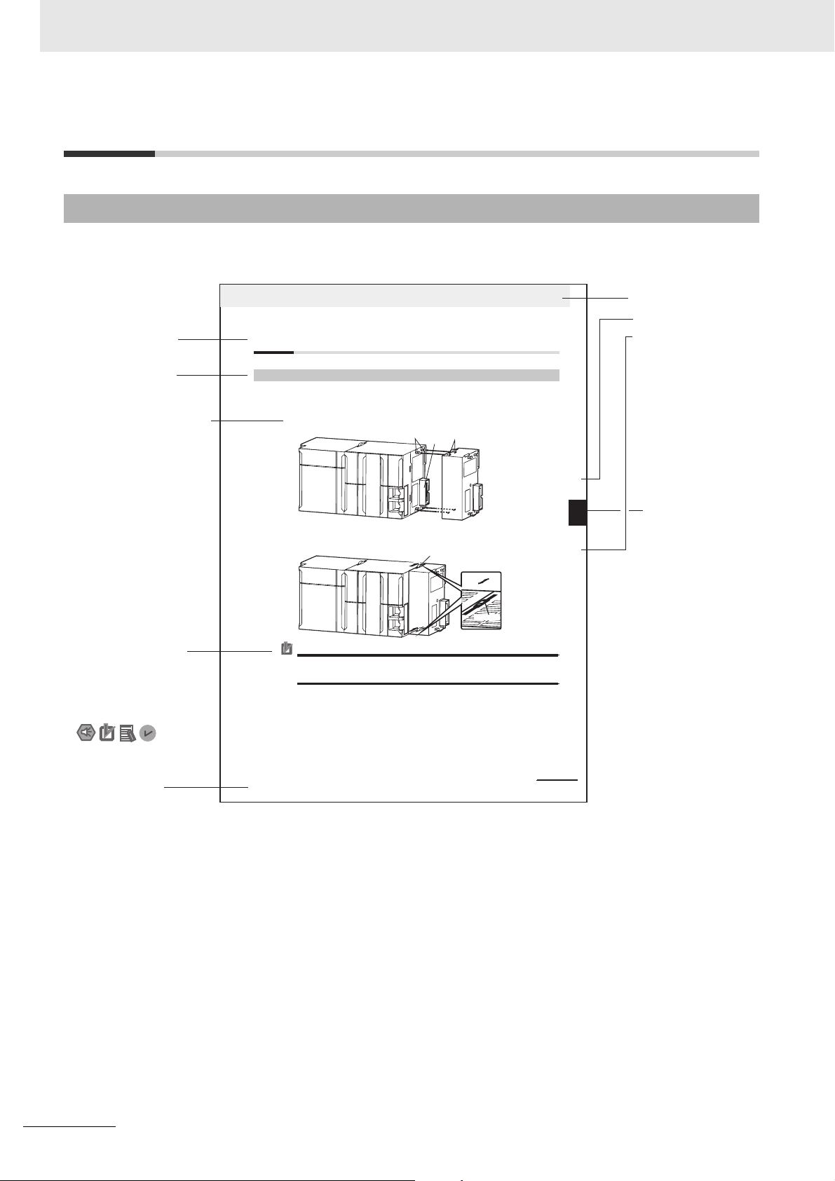
Page Structure and Icons
The following page structure and icons are used in this manual.
Level 2 heading
Level 3 heading
A step in a procedure
Indicates a procedure.
Special information
Icons indicate
precautions, additional
information, or reference
information.
4 Installation and Wiring
4-3 Mounting Units
4-3-1 Connecting Controller Components
The Units that make up an NJ-series Controller can be connected simply by pressing the Units together
and locki ng the slide rs by moving the m toward the back of the U nits. The End Cover is connect ed in the
same way to the Unit on the far right side of the Controller.
1 Join the Units so that the connectors fit exactly.
2 The yellow sliders at the top and bottom of each Unit lock the Units together. Move the sliders
toward the back of the Units as shown below until they click into place.
Precautions for Correct UsePrecautions for Correct Use
The sliders on the tops and bottoms of the Power Supply Unit, CPU Unit, I/O Units, Special I/O
Units, and CPU Bus Units must be completely locked (until they click into place) after connecting
the adjacent Unit connectors.
Hook
Connector
Move the sliders toward the back
until they lock into place.
Hook holes
Release
Lock
Slider
Level 1 heading
Level 2 heading
Level 3 heading
Gives the current
headings.
stinU gnitnuoM 3-4
4
stnenopmoC rellortnoC gnitcennoC 1-3-4
Page tab
Gives the number
of the main section.
Manual name
Note This illustration is provided as a sample only. It may not literally appear in this manual.
2
NJ-series CPU Unit Hardware User’s Manual (W500)
CK3E-series Programmable Multi-Axis Controller Hardware User’s Manual (I610)
4-9
Page 5

Special Information
Special information in this manual is classified as follows:
Precautions for Safe Use
Precautions on what to do and what not to do to ensure safe usage of the product.
Precautions for Correct Use
Precautions on what to do and what not to do to ensure correct operation and performance.
Additional Information
Additional information to read as required.
This information is provided to increase understanding or make operation easier.
Manual Structure
Note References are provided to more detailed or related information.
CK3E-series Programmable Multi-Axis Controller Hardware User’s Manual (I610)
3
Page 6

CONTENTS
CONTENTS
Introduction ..............................................................................................................1
Intended Audience....................................................................................................................................... 1
Applicable Products ..................................................................................................................................... 1
Manual Structure ......................................................................................................2
Page Structure and Icons ............................................................................................................................ 2
Special Information ...................................................................................................................................... 3
CONTENTS................................................................................................................4
Terms and Conditions Agreement..........................................................................7
Warranty, Limitations of Liability .................................................................................................................. 7
Application Considerations .......................................................................................................................... 8
Disclaimers .................................................................................................................................................. 8
Safety Precautions...................................................................................................9
Definition of Precautionary Information........................................................................................................ 9
Symbols....................................................................................................................................................... 9
WARNING ................................................................................................................................................. 10
Precautions for Safe Use.......................................................................................12
Precautions for Correct Use..................................................................................15
Regulations and Standards ...................................................................................17
Conformance to EU Directives .................................................................................................................. 17
Software Licenses and Copyrights ............................................................................................................ 17
Related Manuals .....................................................................................................18
Terms and Acronyms.............................................................................................19
Revision History .....................................................................................................20
Sections in this Manual .........................................................................................21
Section 1 Features and System Configuration
1-1 Features.................................................................................................................................. 1-2
1-2 Introduction to the System Configurations ........................................................................ 1-3
1-3 Support Software................................................................................................................... 1-5
1-4 Application Procedure .......................................................................................................... 1-6
Section 2 Specifications
2-1 Programmable Multi-Axis Controller ................................................................................... 2-2
2-1-1 Model ..........................................................................................................................................2-2
2-1-2 General Specifications ................................................................................................................2-3
2-1-3 Features and Performance Specifications ..................................................................................2-4
2-2 Specifications of Peripherals ............................................................................................... 2-5
2-2-1 USB Memory Device...................................................................................................................2-5
2-2-2 Power Supply.............................................................................................................................. 2-5
4
CK3E-series Programmable Multi-Axis Controller Hardware User’s Manual (I610)
Page 7

Section 3 Part Names and Functions
3-1 Part Names............................................................................................................................. 3-2
3-2 Operation Indicators ............................................................................................................. 3-3
3-3 ID Information Indication Label............................................................................................ 3-4
Section 4 Mounting and Wiring
4-1 Mounting the Programmable Multi-Axis Controller ........................................................... 4-2
4-1-1 Mounting the Programmable Multi-Axis Controller..................................................................... 4-2
4-1-2 Mounting Direction in Control Panels ......................................................................................... 4-3
4-1-3 Mounting Method in Control Panels............................................................................................ 4-3
4-2 Power Supply Wiring............................................................................................................. 4-4
4-2-1 Power Supply Connector Specifications..................................................................................... 4-4
4-2-2 Wiring the Power Supply Connector........................................................................................... 4-4
4-3 Laying the EtherCAT Network .............................................................................................. 4-7
4-3-1 Supported Network Topologies................................................................................................... 4-7
4-3-2 Installation Precautions............................................................................................................... 4-8
4-3-3 Installing EtherCAT Communications Cables ............................................................................. 4-9
4-4 Laying the Ethernet Network.............................................................................................. 4-12
4-4-1 Installation Precautions............................................................................................................. 4-12
4-4-2 Installing Ethernet Networks..................................................................................................... 4-13
4-5 USB Memory Device Connection ....................................................................................... 4-16
CONTENTS
4-6 Grounding ............................................................................................................................ 4-17
4-6-1 Considerations for Earthing Methods ....................................................................................... 4-17
4-6-2 Earthing Methods...................................................................................................................... 4-18
Section 5 Error Processing
5-1 Classification of Errors ......................................................................................................... 5-2
5-2 Using the Indicators to Check Errors .................................................................................. 5-3
5-2-1 Indicator Types ........................................................................................................................... 5-3
5-2-2 Procedure for Determining Errors............................................................................................... 5-4
5-3 Corrective Actions for Errors ............................................................................................... 5-5
5-3-1 Fatal Errors in the Programmable Multi-Axis Controller ............................................................. 5-5
5-3-2 Non-fatal Errors in the Programmable Multi-Axis Controller....................................................... 5-6
Section 6 Inspection and Maintenance
6-1 Cleaning and Maintenance ................................................................................................... 6-2
6-1-1 Cleaning...................................................................................................................................... 6-2
6-1-2 Periodic Inspections.................................................................................................................... 6-2
6-2 Maintenance Procedures ...................................................................................................... 6-4
6-2-1 Unit Replacement Precautions ................................................................................................... 6-4
6-2-2 Backup........................................................................................................................................ 6-4
6-2-3 Unit Replacement....................................................................................................................... 6-4
CK3E-series Programmable Multi-Axis Controller Hardware User’s Manual (I610)
5
Page 8

CONTENTS
Appendices
A-1 Dimension Diagram ...............................................................................................................A-2
A-2 Restrictions on Using the OMRON NX-Series EtherCAT Coupler Unit ............................A-3
Index
6
CK3E-series Programmable Multi-Axis Controller Hardware User’s Manual (I610)
Page 9

Terms and Conditions Agreement
Terms and Conditions Agreement
Warranty, Limitations of Liability
Warranties
z Exclusive Warranty
Omron’s exclusive warranty is that the Products will be free from defects in materials and workmanship for a period of twelve months from the date of sale by Omron (or such other period expressed in
writing by Omron). Omron disclaims all other warranties, express or implied.
z Limitations
OMRON MAKES NO WARRANTY OR REPRESENTATION, EXPRESS OR IMPLIED, ABOUT
NON-INFRINGEMENT, MERCHANTABILITY OR FITNESS FOR A PARTICULAR PURPOSE OF
THE PRODUCTS. BUYER ACKNOWLEDGES THAT IT ALONE HAS DETERMINED THAT THE
PRODUCTS WILL SUITABLY MEET THE REQUIREMENTS OF THEIR INTENDED USE.
Omron further disclaims all warranties and responsibility of any type for claims or expenses based
on infringement by the Products or otherwise of any intellectual property right.
z Buyer Remedy
Omron’s sole obligation hereunder shall be, at Omron’s election, to (i) replace (in the form originally
shipped with Buyer responsible for labor charges for removal or replacement thereof) the non-complying Product, (ii) repair the non-complying Product, or (iii) repay or credit Buyer an amount equal
to the purchase price of the non-complying Product; provided that in no event shall Omron be
responsible for warranty, repair, indemnity or any other claims or expenses regarding the Products
unless Omron’s analysis confirms that the Products were properly handled, stored, installed and
maintained and not subject to contamination, abuse, misuse or inappropriate modification. Return of
any Products by Buyer must be approved in writing by Omron before shipment. Omron Companies
shall not be liable for the suitability or unsuitability or the results from the use of Products in combination with any electrical or electronic components, circuits, system assemblies or any other materials or substances or environments. Any advice, recommendations or information given orally or in
writing, are not to be construed as an amendment or addition to the above warranty.
See http://www.omron.com/global/ or contact your Omron representative for published information.
Limitation on Liability; Etc
OMRON COMPANIES SHALL NOT BE LIABLE FOR SPECIAL, INDIRECT, INCIDENTAL, OR CONSEQUENTIAL DAMAGES, LOSS OF PROFITS OR PRODUCTION OR COMMERCIAL LOSS IN ANY
WAY CONNECTED WITH THE PRODUCTS, WHETHER SUCH CLAIM IS BASED IN CONTRACT,
WARRANTY, NEGLIGENCE OR STRICT LIABILITY.
Further, in no event shall liability of Omron Companies exceed the individual price of the Product on
which liability is asserted.
CK3E-series Programmable Multi-Axis Controller Hardware User’s Manual (I610)
7
Page 10

Terms and Conditions Agreement
Application Considerations
Suitability of Use
Omron Companies shall not be responsible for conformity with any standards, codes or regulations
which apply to the combination of the Product in the Buyer’s application or use of the Product. At
Buyer’s request, Omron will provide applicable third party certification documents identifying ratings
and limitations of use which apply to the Product. This information by itself is not sufficient for a complete determination of the suitability of the Product in combination with the end product, machine, system, or other application or use. Buyer shall be solely responsible for determining appropriateness of
the particular Product with respect to Buyer’s application, product or system. Buyer shall take application responsibility in all cases.
NEVER USE THE PRODUCT FOR AN APPLICATION INVOLVING SERIOUS RISK TO LIFE OR
PROPERTY WITHOUT ENSURING THAT THE SYSTEM AS A WHOLE HAS BEEN DESIGNED TO
ADDRESS THE RISKS, AND THAT THE OMRON PRODUCT(S) IS PROPERLY RATED AND
INSTALLED FOR THE INTENDED USE WITHIN THE OVERALL EQUIPMENT OR SYSTEM.
Programmable Products
Omron Companies shall not be responsible for the user’s programming of a programmable Product, or
any consequence thereof.
Disclaimers
Performance Data
Data presented in Omron Company websites, catalogs and other materials is provided as a guide for
the user in determining suitability and does not constitute a warranty. It may represent the result of
Omron’s test conditions, and the user must correlate it to actual application requirements. Actual performance is subject to the Omron’s Warranty and Limitations of Liability.
Change in Specifications
Product specifications and accessories may be changed at any time based on improvements and other
reasons. It is our practice to change part numbers when published ratings or features are changed, or
when significant construction changes are made. However, some specifications of the Product may be
changed without any notice. When in doubt, special part numbers may be assigned to fix or establish
key specifications for your application. Please consult with your Omron’s representative at any time to
confirm actual specifications of purchased Product.
Errors and Omissions
Information presented by Omron Companies has been checked and is believed to be accurate; however, no responsibility is assumed for clerical, typographical or proofreading errors or omissions.
8
CK3E-series Programmable Multi-Axis Controller Hardware User’s Manual (I610)
Page 11
Safety Precautions
Definition of Precautionary Information
The following notation is used in this manual to provide precautions required to ensure safe usage of
the CK3E-series Programmable Multi-Axis Controller.
The safety precautions that are provided are extremely important to help ensure safety. Always read
and heed the information provided in all safety precautions.
The following notation is used.
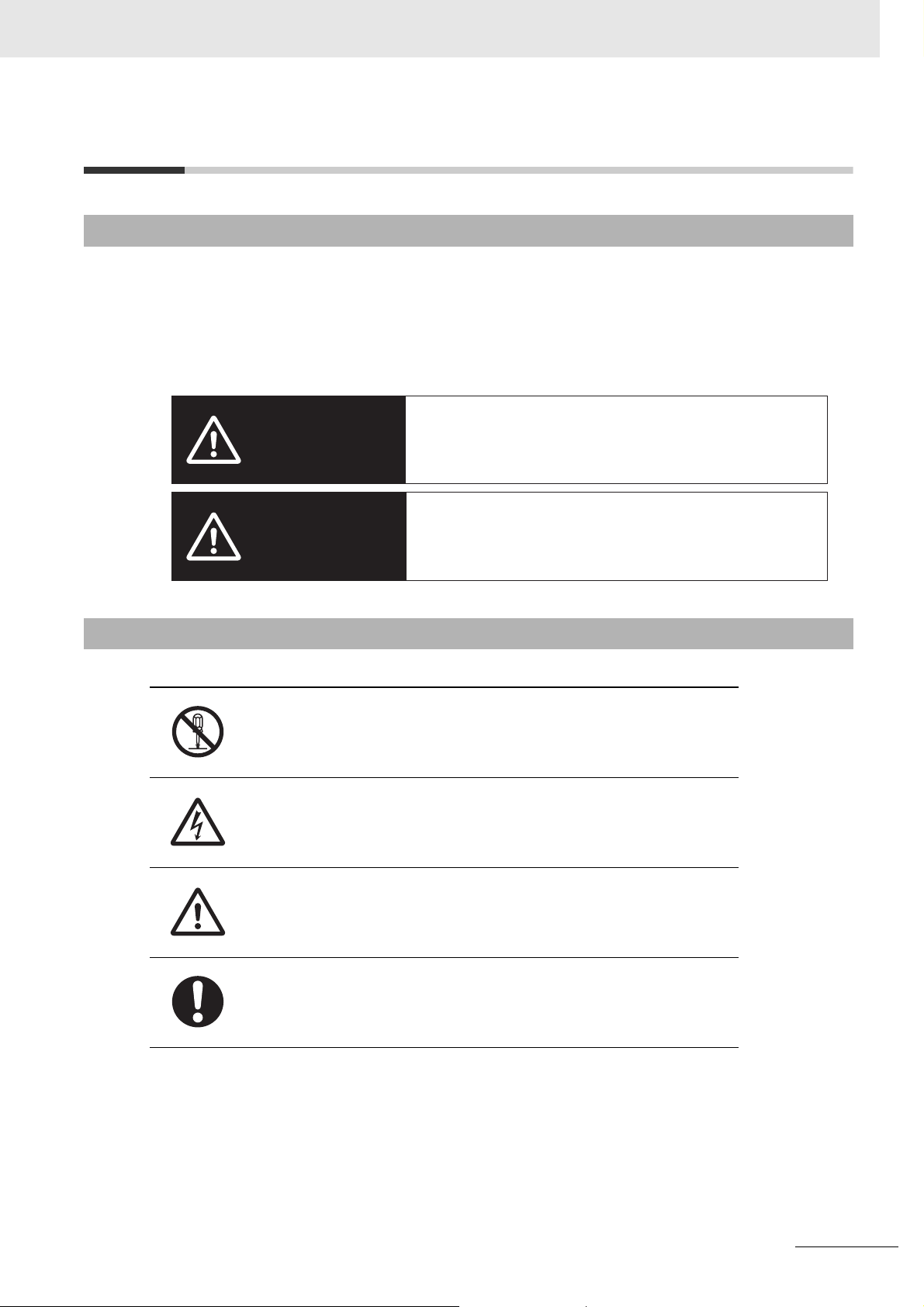
Indicates a potentially hazardous situation which, if not avoided,
WARNING
could result in death or serious injury. Additionally, there may be
severe property damage.
Safety Precautions
Symbols
Indicates a potentially hazardous situation which, if not avoided,
may result in minor or moderate injury, or property damage.
Caution
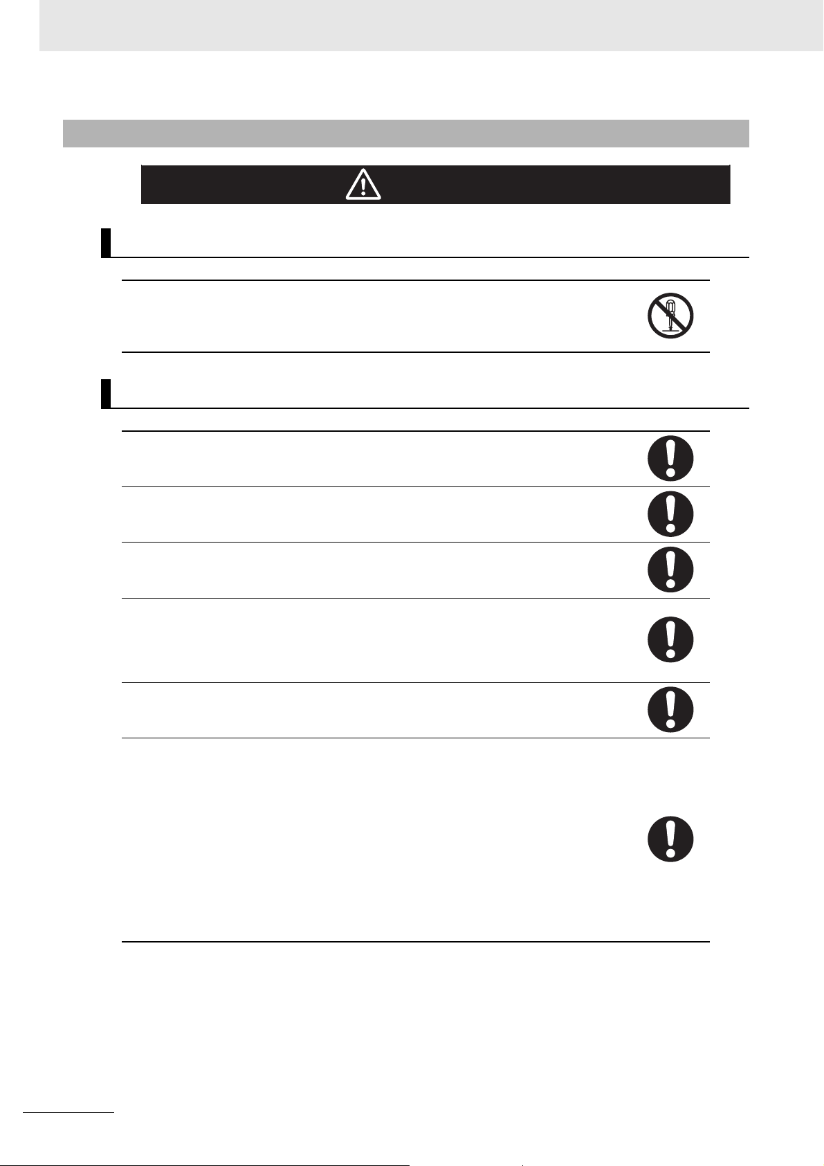
The circle and slash symbol indicates operations that you must not do.
The specific operation is shown in the circle and explained in text.
This example indicates that disassembling is prohibited.
The triangle symbol indicates precautions (including warnings).
The specific operation is shown in the triangle and explained in text.
This example indicates a precaution against electric shock.
The triangle symbol indicates precautions (including warnings).
The specific operation is shown in the triangle and explained in text.
This example indicates a general precaution.
The filled circle symbol indicates operations that you must do.
The specific operation is shown in the circle and explained in text.
This example shows a general precaution for an action you must carry out.
CK3E-series Programmable Multi-Axis Controller Hardware User’s Manual (I610)
9
Page 12
Safety Precautions
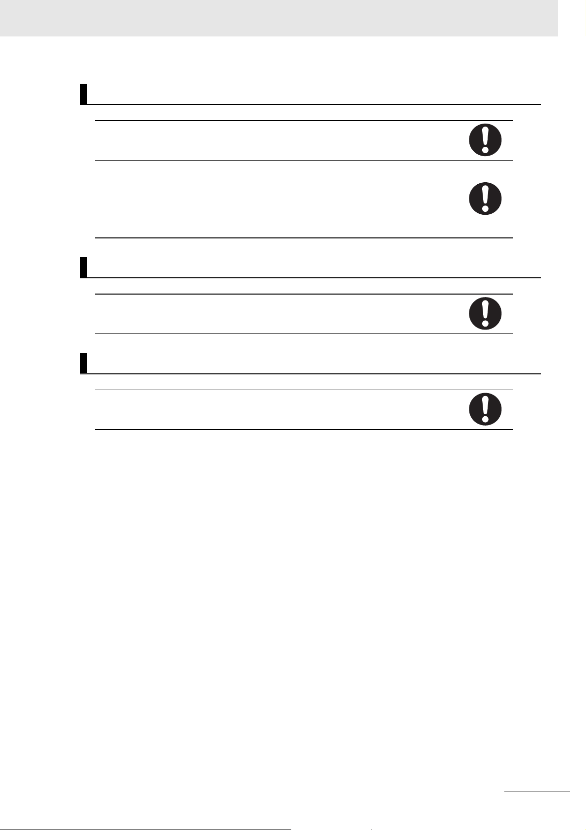
WARNING
During Power Supply
Do not attempt to take any Unit apart.
In particular, high-voltage parts are present in the product while power is supplied or immediately after power is turned OFF. Touching any of these parts may result in electric shock.
There are sharp parts inside the Unit that may cause injury.
Fail-safe Measures
Provide safety measures in external circuits to ensure safety in the system if an abnormality
occurs due to malfunction of the system due to other external factors affecting operation.
Not doing so may result in serious accidents due to incorrect operation.
Emergency stop circuits, interlock circuits, limit circuits, and similar safety measures must
be provided in external control circuits.
WARNING
You must take fail-safe measures to ensure safety in the event of incorrect, missing, or
abnormal signals caused by broken signal lines, momentary power interruptions, or other
causes. Not doing so may result in serious accidents due to incorrect operation.
The use of an Uninterruptible Power Supply (UPS) allows normal operation to continue
even if a momentary power interruption occurs, possibly resulting in the reception of an
erroneous signal from an external device affected by the momentary power failure. Take
external fail-safe measures. Where necessary, monitor the power supply voltage on the
system for external devices and use it as an interlock condition.
Unintended behavior may occur when an error occurs in internal memory of the product.
As a countermeasure for such problems, external safety measures must be provided to
ensure safe operation of the system.
The Controller will turn OFF all outputs from Output Units in the following cases. The slaves
will operate according to the settings in the slaves.
• If a power supply error occurs
• If the power supply connection becomes faulty
• When a CPU error (watchdog timer error) or CPU reset occurs
• If a Controller error in the major fault level occurs
• While the Controller is in startup status until RUN mode is entered after the power is
turned ON.
• If a system initialization error occurs
External safety measures must be provided to ensure safe operation of the system in such
cases.
10
CK3E-series Programmable Multi-Axis Controller Hardware User’s Manual (I610)
Page 13
Safety Precautions
Transferring
Always confirm the safety status at the destination before you transfer a user program, configuration data, or setup data from POWER PMAC IDE. The devices or machines may perform unexpected operations regardless of the operating mode of the Controller.
After you transfer the user program, the Controller is restarted and communications with
the EtherCAT slaves are cut off. During that period, the slave outputs behave according to
the slave specifications.
The time that communications are cut off depends on the EtherCAT network configuration.
Before you transfer the user program, confirm that the system will not be adversely
affected.
Test Run
Before you start a Test Run, make sure that the operation parameters are set correctly.
Actual Operation
Check the user program, data, and parameter settings for proper execution before you use
them for actual operation.
CK3E-series Programmable Multi-Axis Controller Hardware User’s Manual (I610)
11
Page 14

Precautions for Safe Use
Precautions for Safe Use
Transporting
• Do not drop the Controller or expose it to abnormal vibration or shock. Doing so may result in the
Controller malfunctioning or burning.
Mounting
• Be sure that the connectors and other items with locking devices are correctly locked into place.
Installation
• Always connect to a ground of 100 Ω or less when installing the Controller.
Wiring
• Follow the instructions in this manual to correctly perform connector wiring and insertion. Double-check all wiring and connector insertion before turning ON the power supply.
• If the external power supply to a slave has polarity, connect it with the correct polarity. If the polarity is
reversed, current may flow in the reverse direction and damage the connected devices regardless of
the operation of the Controller.
• Before you connect a computer to the Controller, disconnect the power supply plug of the computer
from the AC outlet. Also, if the computer has an FG terminal, make the connections so that the FG
terminal has the same electrical potential as the FG on the product. A difference in electrical potential
between the computer and Controller may cause a failure or malfunction.
• Do not pull on the cables or bend the cables beyond their natural limit.
• Do not place any objects on top of the cables or other wiring lines. Doing so may cause the cables to
break.
• Always use power supply wires with sufficient wire diameters to prevent voltage drop and burning.
Make sure that the current capacity of the wire is sufficient. Otherwise, excessive heat may be generated. When cross-wiring terminals, the total current for all the terminals will flow in the wire. When
wiring cross-overs, make sure that the current capacity of each of the wires is not exceeded.
Power Supply Design
• In the system, only use the power supply within the rated supply capacity range specified in this manual.
12
Turning ON the Power Supply
• It takes approximately several tens of seconds to enter RUN mode after the power supply is turned
ON. During that time, outputs will be OFF or the values will be as according to settings in the Unit or
slaves. Also, external communications will not be able to be performed. The outputs during this
period will behave according to the slave and Unit specifications. Implement fail-safe circuits so that
external devices do not operate incorrectly.
• Surge current occurs when the power supply is turned ON. When selecting fuses or breakers for
external circuits, consider the above precaution and allow sufficient margin in shut-off performance.
Refer to this manual for surge current specifications.
CK3E-series Programmable Multi-Axis Controller Hardware User’s Manual (I610)
Page 15

Precautions for Safe Use
Turning OFF the Power Supply
• Do not turn off the power supply or remove the USB memory device while the Controller is accessing
the USB memory device. Data may become corrupted, and the Controller will not operate correctly if
it uses corrupted data.
• Always turn OFF the power supply before you attempt any of the following.
Connecting cables or wiring the system
Connecting or disconnecting the connectors
• If the product experiences a sudden loss of power or disconnecting the cable while saving a setting
or transfer of data is underway, the changes may not be stored and unexpected behavior may occur.
Operation
Confirm that no adverse effects will occur in the system before you attempt any of the following.
• Changing the operating mode of the Controller (including changing the setting of the Startup Mode)
• Changing the user program or settings
• Changing set values or present values
EtherCAT Communications
• Make sure that the communications distance, number of nodes connected, and method of connection for EtherCAT are within specifications.
Do not connect EtherCAT communications to EtherNet/IP, a standard in-house LAN, or other networks. An overload may cause the network to fail or malfunction.
• If the Fail-soft Operation parameter is set to stop operations, process data communications will stop
for all slaves when an EtherCAT communications error is detected in a slave. For this reason, if
Servo Drives are connected, the Servos for all axes will be turned OFF. At that time, the Servo Drive
will operate according to the Servo Drive specifications. Make sure that the Fail-soft Operation
parameter setting results in safe operation when a device error occurs.
• If noise occurs or an EtherCAT slave is disconnected from the network, any current communications
frames may be lost. If frames are lost, slave I/O data is not communicated, and unintended operation
may occur. The slave outputs behave according to the slave specifications. For details, refer to relevant manuals for each slave.
• When an EtherCAT slave is disconnected or disabled, communications will stop and control of the
outputs will be lost not only for the disconnected slave, but for all slaves connected after it. Confirm
that the system will not be adversely affected before you disconnect or disable a slave.
• You cannot use standard Ethernet hubs or repeater hubs with EtherCAT communications. If you use
one of these, a major fault level error or other error may occur.
• EtherCAT communications are not always established immediately after the power supply is turned
ON. Use the system-defined variables and the EtherCAT Coupler Unit device variables in the user
program to confirm that I/O data communications are established before attempting control operations.
• If you need to disconnect the cable from an EtherCAT slave during operation, first reset the EtherCAT
and EtherCAT slaves that are connected after it to the Init state, then disconnect the EtherCAT slave.
• For EtherCAT and EtherNet, use the connection methods and cables that are specified in this manual. Otherwise, communications may be faulty.
• Make sure that all of the slaves to be restored are participating in the network before you reset the
EtherCAT Master Function Module. If any slave is not participating when any of these errors is reset,
the EtherCAT Master Function Module may access a slave with a different node address than the
specified node address, or the error may not be reset correctly.
CK3E-series Programmable Multi-Axis Controller Hardware User’s Manual (I610)
13
Page 16

Precautions for Safe Use
Motion Control
• The motor is stopped if communications are interrupted between POWER PMAC IDE and the Controller during a Test Run. Connect the communications cable securely and confirm that the system
will not be adversely affected before you perform a Test Run.
• EtherCAT communications are not always established immediately after the power supply is turned
ON. Use the system-defined variables in the user program to confirm that communications are established before attempting control operations.
Unit Replacement
• After replacing the Controller, make sure that the required data, including the user program, configurations, settings, and values of variables, has been transferred to the Controller that was replaced, as
well as to externally connected devices before restarting operation.
Maintenance
• Do not attempt to disassemble, repair, or modify the Controller. Doing so may result in a malfunction
or fire.
• Do not use corrosive chemicals to clean the Controller. Doing so may result in a failure or malfunction
of the Controller.
14
CK3E-series Programmable Multi-Axis Controller Hardware User’s Manual (I610)
Page 17

Precautions for Correct Use
Storage and Installation
• Follow the instructions in this manual to correctly perform installation.
• Do not operate or store the Controller in the following locations. Doing so may result in a malfunction
or halt operations.
a) Locations subject to direct sunlight
b) Locations subject to temperatures or humidity outside the range specified in the specifications
c) Locations subject to condensation as a result of severe changes in temperature
d) Locations subject to corrosive or flammable gases
e) Locations subject to dust (especially iron dust) or salts
f) Locations subject to exposure to water, oil, or chemicals
g) Locations subject to shock or vibration
• Take appropriate and sufficient countermeasures when installing the Controller in the following locations.
a) Locations subject to strong, high-frequency noise
b) Locations subject to static electricity or other forms of noise
c) Locations subject to strong electromagnetic fields
d) Locations subject to possible exposure to radioactivity.
e) Locations close to power lines
• Install the Controller away from sources of heat and ensure appropriate ventilation. Not doing so may
result in a malfunction, operations halting, or burning.
• Always touch a grounded piece of metal to discharge static electricity from your body before starting
an installation or maintenance procedure.
Precautions for Correct Use
Wiring
• Do not allow wire clippings, shavings, or other foreign material to enter the Controller. Otherwise, the
Controller may experience a failure, malfunction, or ignite. Cover the Controller or take other suitable
countermeasures, in particular when carrying out wiring work.
• Always ensure the rated supply voltage is connected to the Controller.
Task Settings
• If a Task Period Exceeded error occurs, shorten the programs to fit in the task or increase the setting
of the task period.
Operation
• Do not disconnect the communications cable while the system is running. Doing so may result in a
failure or malfunction of the system.
Motion Control
• Do not download motion control settings during a Test Run.
CK3E-series Programmable Multi-Axis Controller Hardware User’s Manual (I610)
15
Page 18

Precautions for Correct Use
EtherCAT Communications
• Set the Servo Drives to stop operation if an error occurs in EtherCAT communications between the
Controller and a Servo Drive.
• Always use the specified EtherCAT slave cables. If you use any other cable, the EtherCAT master or
the EtherCAT slaves may detect an error and one of the following may occur.
a) Continuous refreshing of process data communications will not be possible.
b) Continuous refreshing of process data communications will not end during the set cycle.
USB Device
• Always use USB memory devices that comply with the USB standards.
16
CK3E-series Programmable Multi-Axis Controller Hardware User’s Manual (I610)
Page 19

Regulations and Standards
Conformance to EU Directives
Applicable Directives
•EMC Directives
Concepts
z EMC Directives
OMRON devices that comply with EU Directives also conform to the related EMC standards so that
they can be more easily built into other devices or the overall machine. The actual products have
been checked for conformity to EMC standards.*1
Regulations and Standards
Whether the products conform to the standards in the system used by the customer, however, must
be checked by the customer. EMC-related performance of the OMRON devices that comply with EU
Directives will vary depending on the configuration, wiring, and other conditions of the equipment or
control panel on which the OMRON devices are installed. The customer must, therefore, perform
the final check to confirm that devices and the overall machine conform to EMC standards.
*1. Applicable EMC (Electromagnetic Compatibility) standards are as follows:
EMS (Electromagnetic Susceptibility): EN 61326
EMI (Electromagnetic Interference): EN 61326 (Radiated emission: 10-m regulations).
z Conformance to EU Directives
The CK3E-series Controllers comply with EU Directives. To ensure that the machine or device in
which the CK3E-series Controllers are used complies with EU Directives, the following precautions
must be observed.
• The CK3E-series Controllers must be installed within a control panel.
• You must use SELV power supply for the DC power supplies that are connected as the Unit power
supplies and I/O power supplies for the CK3E-series Controllers.
We recommend that you use the OMRON S8JX-series Power Supplies. EMC standard compliance was confirmed for the recommended Power Supplies.
• CK3E-series Controllers that comply with EU Directives also conform to the Common Emission
Standard (EN 61326). Radiated emission characteristics (10-m regulations) may vary depending
on the configuration of the control panel used, other devices connected to the control panel, wiring, and other conditions.
You must therefore confirm that the overall machine or equipment in which the CK3E-series Controllers are used complies with EU Directives.
• This is a Class A product (for industrial environments). In a residential environment, it may cause
radio interference. If radio interference occurs, the user may be required to take appropriate measures.
• Attach a clamp core to the Ethernet communications cable. Refer to Recommended Clamp Core
and Attachment Procedure on page 4-15 for details of the procedure to attach the clamp core.
Software Licenses and Copyrights
This product incorporates certain third party software. The license and copyright information associated
with this software is available at http://www.fa.omron.co.jp/nj_info_e/.
CK3E-series Programmable Multi-Axis Controller Hardware User’s Manual (I610)
17
Page 20

Related Manuals
Related Manuals
The following manuals are related. Contact your OMRON representative for information on how to procure these manuals. Use these manuals for reference.
Manual name Cat.No. Application Description
Power PMAC User’s
Manual
Power PMAC Software
Reference Manual
Power PMAC IDE User
Manual
Power PMAC-NC16 Quick
Start Manual
Power PMAC-NC16 .ini
Configuration Manual
Power PMAC-NC16
Software User Manual
Power PMAC-NC16 Mill
G-Code Manual
Acontis EC-Engineer
manual
O014 Learning the features and usage
examples of the CK3E-series Programmable Multi-Axis Controller.
O015 Learning how to program a
CK3E-series Programmable
Multi-Axis Controller.
O016 Learning how to operate Power
PMAC IDE, the integrated development environment of the Controller.
O017 Understanding the basic usage of
Power PMAC-NC16 quickly.
O018 Constructing an application for CNC
devices by using Power
PMAC-NC16.
O019 Learning about usage and features
of Power PMAC-NC16, Support Software required when using the Controller for CNC devices.
O020 Creating programs for CNC devices
by using Power PMAC-NC16.
--- Configuring an EtherCAT network by
using a CK3E-series Programmable
Multi-Axis Controller as the EtherCAT
master.
The following information is provided on
a CK3E-series Programmable Multi-Axis
Controller.
• Basic features of the motion controller
Power Programmable Multi-Axis Controller possessed by the Programmable Multi-Axis Controller.
• Setup examples
• Programming examples
The following information is provided on
a CK3E-series Programmable Multi-Axis
Controller.
• Details of commands
• Details of data structure
Describes the operating procedures of
Power PMAC IDE, and examples of how
to start the system.
Describes a Quick setup procedure to
run Power PMAC-NC16 on a desktop
PC by using an example.
Describes how to set up
“PowerPmacNC.ini”, the setup data file
to be loaded when Power PMAC-NC16
starts.
The following information is provided on
Power PMAC-NC16.
• How to use the software
• Features included in the software
• Features that can be customized
Describes the basic G-code set and the
instructions that can be used for Power
PMAC-NC16.
Operating procedure of Support Software used for EtherCAT network configuration is described.
18
CK3E-series Programmable Multi-Axis Controller Hardware User’s Manual (I610)
Page 21

Terms and Acronyms
Terms and Acronyms
Term or acronym Description
CNC The acronym for Computerized Numerical Control.
A method to numerically control machining processes in production by using computers.
CNC has been further automatized over conventional numerical control machine tools (NC
machine tools).
CPU Central Processing Unit. Core hardware mounted in computers that executes instructions
from computer programs.
ESI file ESI is the acronym for EtherCAT Slave Information. The ESI file contains information
unique to the EtherCAT slaves in XML format.
ENI file ENI is the acronym for EtherCAT Network Information. The ENI file contains the network
configuration information related to EtherCAT slaves.
Ethernet A network communications protocol used in TCP/IP networks.
EtherCAT The acronym for Ethernet for Control Automation Technology.
EtherCAT is the real-time Ethernet protocol standards.
EtherCAT master The EtherCAT master node that manages the EtherCAT network, monitors the status of
slaves, and exchanges I/O data with slaves. It has one output port.
G-code A type of language used to create NC programs.
Modbus/TCP A protocol used for the Modbus communication on TCP/IP.
PLC Programmable Logic Controller
PMAC The acronym for Programmable Multi-Axis Controller
USB Universal Serial Bus
Servo Drive/Encoder input
slave
Vision sensor A sensor that calculates the area, center of gravity, length, position, and other feature quan-
Axis A functional unit within the Motion Control Function Module. An axis is assigned to the drive
Node address The node address is used to identify Units connected to EtherCAT.
General-purpose slave Any of the EtherCAT slaves that cannot be assigned to an axis.
Programmable terminal A human-machine interface used to facilitate the operation and control of machines.
Motion control Motion control can achieve intended operation by providing a target value to the axis to be
Any of the EtherCAT slaves that is assigned to an axis.
tities of objects by processing images captured using a camera, and outputs the data and
judgment results.
mechanism in an external Servo Drive or the sensing mechanism in an external Encoder
Input Slave Unit.
controlled, or by controlling state transitions.
CK3E-series Programmable Multi-Axis Controller Hardware User’s Manual (I610)
19
Page 22
Revision History
Revision History
A manual revision code appears as a suffix to the catalog number on the front and back covers of the
manual.
I610-E1-01
Revision code
Revision
code
01 August 2016 Original production
Date Revised content
20
CK3E-series Programmable Multi-Axis Controller Hardware User’s Manual (I610)
Page 23
Sections in this Manual
Sections in this Manual
1
Features and System
1A
2I
3
4
5
6
Configuration
Specifications
Part Names and
Functions
Mounting and Wiring
Error Processing
Inspection and Maintenance
2
3
4
5
6
A
I
A
I
Appendices
Index
9
CK3E-series Programmable Multi-Axis Controller Hardware User’s Manual (I610)
9
21
Page 24

Sections in this Manual
22
CK3E-series Programmable Multi-Axis Controller Hardware User’s Manual (I610)
Page 25

1
Features and System Configuration
This section describes the features and system configuration of the Programmable
Multi-Axis Controller.
1-1 Features . . . . . . . . . . . . . . . . . . . . . . . . . . . . . . . . . . . . . . . . . . . . . . . . . . . . . 1-2
1-2 Introduction to the System Configurations . . . . . . . . . . . . . . . . . . . . . . . . . 1-3
1-3 Support Software . . . . . . . . . . . . . . . . . . . . . . . . . . . . . . . . . . . . . . . . . . . . . . 1-5
1-4 Application Procedure . . . . . . . . . . . . . . . . . . . . . . . . . . . . . . . . . . . . . . . . . . 1-6
1
CK3E-series Programmable Multi-Axis Controller Hardware User’s Manual (I610)
1 - 1
Page 26

1 Features and System Configuration
1-1 Features
The CK3E-series is the Programmable Multi-Axis Controller that supports the EtherCAT master functions.
The CK3E-series Programmable Multi-Axis Controller has the following features.
Fast Multi-Axis Control
The Controller uses Programmable Multi-Axis Controller, developed by Delta Tau Data Systems, Inc., a
manufacturer specializing in motion controllers.
It allows for multi-axis control of up to 32 axes per unit (when CK3E-1410 is used), and the fast control
which motion control period is 250 μs or more.
Constructing Systems with Greater Flexibility
Programs can be written in G-code, C language, or Programmable Multi-Axis Controller specific language for the Controller. Such function design flexibility allows you to create functions that are optimized for your equipment.
Various EtherCAT-compatible products such as vision sensors and I/O as well as motion controls can
be connected, allowing you to construct original systems to suit the equipment.
Compactness
The Controller is compact and has less wiring due to the use of the EtherCAT network, which helps to
downsize devices.
Additional Information
What is EtherCAT?
EtherCAT is an Ethernet (IEEE802.3) compliant, open, and super-fast industrial network system.
Each node achieves a short communications cycle time by transmitting Ethernet frames at high
speed. A mechanism that allows sharing of clock information enables high-precision synchronized control with low communications jitter.
1 - 2
CK3E-series Programmable Multi-Axis Controller Hardware User’s Manual (I610)
Page 27

1 Features and System Configuration
1-2 Introduction to the System
1-2 Introduction to the System Configu-
rations
The following shows the configurations of motion control systems using a Programmable Multi-Axis
Controller. The basic configurations include the EtherCAT network configuration, Ethernet network configuration, and Support Software.
EtherCAT Network Configuration
By using the EtherCAT master communications port on the Programmable Multi-Axis Controller, EtherCAT slaves such as servo drives, frequency inverters, machine vision systems, digital and analog I/O,
and other general-purpose slaves can be connected.
The Controller also supports EtherCAT Slave Terminals. The EtherCAT Slave Terminal helps you to
save space and construct flexible systems using a broad range of types of NX Units.
However, when OMRON NX-series EtherCAT Coupler Units are used for the EtherCAT Slave Terminal,
only limited models and unit versions of EtherCAT Coupler Units can be connected. Refer to A-2
Restrictions on Using the OMRON NX-Series EtherCAT Coupler Unit on page A-3.
Ethernet Network Configuration
Configurations
1
The Ethernet communications port on the Programmable Multi-Axis Controller supports the MODBUS-TCP protocol. It can be connected to devices such as a PLC or a programmable terminal that supports the MODBUS-TCP protocol.
Support Software
Connect a personal computer with the Support Software installed to the Programmable Multi-Axis Controller via the Ethernet network. Refer to 1-3 Support Software on page 1-5 for details of the Support
Software.
CK3E-series Programmable Multi-Axis Controller Hardware User’s Manual (I610)
1 - 3
Page 28

1 Features and System Configuration
Support Software
PLC
Programmable terminal
Programmable terminal
Modbus-TCP
Ethernet network
Industrial
Ethernet
switch
Slave
terminal
CK3E-series Programmable
Multi-Axis Controller
EtherCAT network
Servo drive/
Encoder
General-purpose
input slaves
slaves
1 - 4
CK3E-series Programmable Multi-Axis Controller Hardware User’s Manual (I610)
Page 29

1-3 Support Software
The following table shows the Support Software used to configure, monitor, program, and debug the
Programmable Multi-Axis Controller.
Software Name Application How to Procure
Power PMAC IDE
Power
PMAC-NC16
EC-Engineer This computer software is used to configure
*1. Use Power PMAC IDE Ver.2.2 or a later version.
*1
Power
PMAC-NC16
SDK
Power
PMAC-NC16
Runtime
This computer software is used to configure
the Controller, create user programs, and
debug the programs.
This computer software is used to control
working machines and other CNC machines
with the Controller. Use this software when you
want to customize the HMI screen. The product contains extension source codes used for
customization.
This computer software is used to control
working machines and other CNC machines
with the Controller. Use this software when you
do not customize the HMI screen.
and monitor the EtherCAT network by using
the Controller as the EtherCAT master.
1 Features and System Configuration
This is free software. Contact
your OMRON representative for information on how to
procure.
This is non-free software.
Contact your OMRON representative for information on
how to procure.
This is non-free software.
Contact your OMRON representative for information on
how to procure.
This is free software. Contact
your OMRON representative for information on how to
procure.
1-3 Support Software
1
CK3E-series Programmable Multi-Axis Controller Hardware User’s Manual (I610)
1 - 5
Page 30

1 Features and System Configuration
1-4 Application Procedure
This section describes the procedure to construct a motion control system by using the Multi-Axis Controller.
No. Step Description Reference
1 Preparation
before carrying
out work
2 Mounting and
wiring of the
Programmable Multi-Axis
Controller
3 Settings and
wiring of the
EtherCAT
slave hardware.
4 Wiring of the EtherCAT communi-
cation and grounding of the system
5 Preparation for
setting the
Programmable Multi-Axis
Controller
6 Turning the Power ON Turn on the power to the devices
Check for speci-
fication compati-
bility
Selection of
peripheral
devices
Preparation of
Support Soft-
ware
Mounting Mount the Programmable
Wiring Connect the unit power supply of
Node address
settings
Mounting Mount EtherCAT slaves. Refer to the manual for the Ether-
Wiring Wire EtherCAT slaves.
Creation of a
new project
Initialization of
the Controller
Check whether the system is
compatible with specifications of
the Programmable Multi-Axis
Controller.
• General specifications
• Mounting direction
Select peripheral devices to be
used for the Programmable
Multi-Axis Controller.
Procure and install the Support
Software required for the system.
Multi-Axis Controller.
the Programmable Multi-Axis
Controller.
Use the hardware switches on all
of the EtherCAT slaves in the network to set the node addresses.
• Wiring of the unit power supply
• I/O wiring
Ground and wire the EtherCAT
communication cable.
Connect the computer with the
Support Software installed to the
Programmable Multi-Axis Controller. Then start Power PMAC
IDE and create a new project.
Initialize the Programmable
Multi-Axis Controller by using
Power PMAC IDE.
configuring the system.
2-1-2 General Specifications on
page 2-3
2-2 Specifications of Peripherals
on page 2-5
1-3 Support Software on page 1-5
4-1 Mounting the Programmable
Multi-Axis Controller on page 4-2
4-2 Power Supply Wiring on page
4-4
Refer to the manual for the EtherCAT slave.
CAT slave.
Refer to the manual for the EtherCAT slave.
4-3 Laying the EtherCAT Network
on page 4-7
4-6 Grounding on page 4-17
Refer to “Power PMAC IDE User
Manual” for details.
Refer to “Power PMAC IDE User
Manual” for details.
---
1 - 6
CK3E-series Programmable Multi-Axis Controller Hardware User’s Manual (I610)
Page 31

1 Features and System Configuration
No. Step Description Reference
7 Construction
of the EtherCAT network
8 Settings of the
Programmable Multi-Axis
Controller
operation
9 Transferring project data and
checking the operation
Installation of
ESI files
EtherCAT slave
settings
Activation of the
EtherCAT network
Programming Create user programs on Power
Motor settings Set the motor operations for the
Install the ESI files of EtherCAT
slaves to be connected to
EC-Engineer.
Configure the EtherCAT communication settings by using
EC-Engineer. Then, create an
ENI file used to download the
configured settings to the Programmable Multi-Axis Controller.
Download the ENI file to the Programmable Multi-Axis Controller
by using Power PMAC IDE. Make
sure that the ENI file has been
correctly downloaded, and then
activate the EtherCAT network.
PMAC IDE.
Programmable Multi-Axis Controller by using Power PMAC IDE.
Transfer the created project data
and check that operations work
as expected.
Refer to “Acontis EC-Engineer
manual” for details.
For information on the ESI file,
refer to the manual for the EtherCAT slave.
Refer to “Acontis EC-Engineer
manual” for details.
Refer to “Power PMAC IDE User
Manual” for details.
Refer to “Power PMAC User’s
Manual” and “Power PMAC Software Reference Manual” for
details.
Refer to “Power PMAC IDE User
Manual” for details.
Refer to “Power PMAC IDE User
Manual” for details.
1-4 Application Procedure
1
CK3E-series Programmable Multi-Axis Controller Hardware User’s Manual (I610)
1 - 7
Page 32

1 Features and System Configuration
1 - 8
CK3E-series Programmable Multi-Axis Controller Hardware User’s Manual (I610)
Page 33

Specifications
This section describes the specifications of the Programmable Multi-Axis Controller
and configuration devices.
2-1 Programmable Multi-Axis Controller . . . . . . . . . . . . . . . . . . . . . . . . . . . . . . 2-2
2-1-1 Model . . . . . . . . . . . . . . . . . . . . . . . . . . . . . . . . . . . . . . . . . . . . . . . . . . . . . . . 2-2
2-1-2 General Specifications . . . . . . . . . . . . . . . . . . . . . . . . . . . . . . . . . . . . . . . . . . 2-3
2-1-3 Features and Performance Specifications . . . . . . . . . . . . . . . . . . . . . . . . . . . 2-4
2-2 Specifications of Peripherals . . . . . . . . . . . . . . . . . . . . . . . . . . . . . . . . . . . . 2-5
2-2-1 USB Memory Device . . . . . . . . . . . . . . . . . . . . . . . . . . . . . . . . . . . . . . . . . . . 2-5
2-2-2 Power Supply . . . . . . . . . . . . . . . . . . . . . . . . . . . . . . . . . . . . . . . . . . . . . . . . . 2-5
2
2
CK3E-series Programmable Multi-Axis Controller Hardware User’s Manual (I610)
2 - 1
Page 34

2 Specifications
2-1 Programmable Multi-Axis Controller
The following provides the models and major specifications of the Programmable Multi-Axis Controller
and configuration devices.
2-1-1 Model
Model Naming
CK3E-series Programmable Multi-Axis Controller model names are assigned according to the following
rule.
Maximum number of controlled axes
12 : 8 axes
13 : 16 axes
14 : 32 axes
Number of EtherCAT ports
1 : 1 port
Always 0
Model List
Specifications
Model
CK3E-1210 Main memory: 1 GB
CK3E-1310 16 axes
CK3E-1410 32 axes
Memory Port
Flash memory: 1 GB
Ethernet port: 1
EtherCAT port: 1
Maximum
number of
controlled axes
8 axes
2 - 2
CK3E-series Programmable Multi-Axis Controller Hardware User’s Manual (I610)
Page 35

2 Specifications
2-1-2 General Specifications
Item
Model CK3E-1210 Model CK3E-1310 Model CK3E-1410
Enclosure Mounted in a panel
Grounding methods Ground of 100 Ω or less
Dimensions (height × depth × width) 130.4 × 28.6 × 170.9 mm (H × D × W)
Weight 540 g or less
Unit power supply rated voltage 24 VDC (20.4 to 26.4 VDC)
Unit power current consumption 660 mA or less
Operating
environment
Ambient operating
temperature
Ambient operating
0 to 45°C
10 to 95% RH (without condensation and icing)
humidity
Atmosphere Must be free of corrosive gases.
Ambient storage tem-
-25 to +70°C (without condensation and icing)
perature
Vibration resistance Conforms to IEC 60068-2-6.
5 to 8.4 Hz with 3.5-mm amplitude, 8.4 to 150 Hz, acceleration of 9.8 m/s
X, Y, and Z directions
100 min (10 sweeps of 10 min each = 100 min total)
Shock resistance
Conforms to IEC 60068-2-27, 147 m/s
Applicable standards *1 EU: EN 61326, RCM
*1. For the latest applicable standards for each model, visit the OMRON website (www.fa.omron.co.jp or
www.ia.omron.com), or contact your OMRON representative.
Specifications
2
, 3 times each in X, Y, and Z directions
2
each in
2-1 Programmable Multi-Axis Controller
2
2-1-2 General Specifications
CK3E-series Programmable Multi-Axis Controller Hardware User’s Manual (I610)
2 - 3
Page 36

2 Specifications
2-1-3 Features and Performance Specifications
Item
Memory Main memory: 1 GB
External terminals [Communications connector]
Motion control
EtherCAT
communications
specifications
Ethernet
communications
specifications
USB port Physical layer USB 3.0 compliant, type A connector. Output voltage: 5 V, 0.9 A max.
Maximum number of
controlled axes
Motion control period 250 μs or more
Control method Issuing control commands using EtherCAT communications
Communications protocol
Baud rate 100 Mbps
Physical layer 100BASE-TX (IEEE 802.3)
Topology Line, daisy chain, and branching
Transmission media Twisted-pair cable of category 5 or higher (double-shielded cable with aluminum
Transmission distance Distance between nodes: 100 m or less
Maximum number of
slaves
Range of node
addresses that can be
set
Physical layer 1000BASE-T/100BASE-TX
Frame length 1,514 bytes max.
Media access method CSMA/CD
Modulation Baseband
Topology Star
Transmission media Twisted-pair cable of category 5, 5e, or higher (shielded cable)
Maximum transmission distance between
Ethernet switch and
node
Maximum number of
cascade connections
Transmission distance 3 m max.
Model CK3E-1210 Model CK3E-1310 Model CK3E-1410
Flash memory: 1 GB
For EtherCAT communications
•RJ45 × 1 (Shield supported)
For Ethernet communications
•RJ45 × 1 (Shield supported)
[Power supply input terminal]
For unit power supply × 1
[USB port]
For external memory connection, USB 3.0 host × 1 Type A
8 axes 16 axes 32 axes
EtherCAT protocol
tape and braiding)
32
1 to 32
100 m
There are no restrictions if an Ethernet switch is used.
Specifications
2 - 4
CK3E-series Programmable Multi-Axis Controller Hardware User’s Manual (I610)
Page 37

2-2 Specifications of Peripherals
2-2-1 USB Memory Device
The following shows details of the recommended USB memory device.
OMRON is not responsible for the operation, performance, or write life of any other USB memory
devices.
Recommended USB
memory
Model FZ-MEM2G OMRON USB memory device (2 GB)
Model FZ-MEM8G OMRON USB memory device (8 GB)
You can use the USB memory device for the following applications.
• Uploading data
• Downloading data
• Saving relevant data
Description
2 Specifications
2-2 Specifications of Peripherals
2
2-2-1 USB Memory Device
2-2-2 Power Supply
The following shows details of the recommended power supply.
Recommended power supply: Model S8JX series (OMRON)
For specifications and manuals of Model S8JX, visit the OMRON website
(http://www.fa.omron.co.jp/products/family/1989/lineup.html).
CK3E-series Programmable Multi-Axis Controller Hardware User’s Manual (I610)
2 - 5
Page 38

2 Specifications
2 - 6
CK3E-series Programmable Multi-Axis Controller Hardware User’s Manual (I610)
Page 39

3
Part Names and Functions
This section describes the names and functions of the Programmable Multi-Axis Controller.
3-1 Part Names . . . . . . . . . . . . . . . . . . . . . . . . . . . . . . . . . . . . . . . . . . . . . . . . . . . 3-2
3-2 Operation Indicators . . . . . . . . . . . . . . . . . . . . . . . . . . . . . . . . . . . . . . . . . . . 3-3
3-3 ID Information Indication Label . . . . . . . . . . . . . . . . . . . . . . . . . . . . . . . . . . 3-4
3
CK3E-series Programmable Multi-Axis Controller Hardware User’s Manual (I610)
3 - 1
Page 40

3 Part Names and Functions
3-1 Part Names
(C)
(B)
(A)
(D)
(E)
(J)
(I)
Letter Name Function
(A) USB 3.0 connector The connector of USB 3.0 interface, used to connect a USB
memory device.
(B) Maintenance mode LED Not used. Used for maintenance.
(C) Maintenance mode enter button Not used. Used to enter Maintenance mode. The user does
not use it.
(D) USB 2.0 connector Not used. Used for maintenance. The user does not use it.
(E) Power supply connector Connects to the Unit power supply.
(F) EtherCAT communications port opera-
tion indicators
(G) Ethernet communications port opera-
tion indicators
(H) Unit operation indicators Show the operation status of the Unit using multiple indicators.
(I) Ethernet communications connector Connects to an Ethernet network communications cable.
(J) EtherCAT communications connector Connects to an EtherCAT network communications cable.
Show the operation status of EtherCAT.
Show the operation status of Ethernet.
(F)
(G)
(H)
3 - 2
CK3E-series Programmable Multi-Axis Controller Hardware User’s Manual (I610)
Page 41

3-2 Operation Indicators
The Programmable Multi-Axis Controller is equipped with indicators to show the current operations status of the Unit.
(A)
(B)
3 Part Names and Functions
3-2 Operation Indicators
3
(C)
(D)
(E)
(F)
(G)
The operating statuses corresponding to colors and status of the indicators are shown below.
Letter Indicator Color Status Description
(A) DIAG.MODE Green Lit Not used.
(B) ECAT LINK Orange Lit The EtherCAT link is established.
Not lit The EtherCAT link is not established.
(C) ECAT ACT Yellow Lit The EtherCAT link is established.
Flashing Data communications are in progress after the
EtherCAT link is established.
Flashes every time data is sent or received.
Not lit The EtherCAT link is not established.
(D) Ethernet LINK Green/
Orange
(E) Ethernet ACT Yellow Lit The Ethernet link is established.
(F) PWR/ERR Green/Red Lit in green Power is supplied to the Unit.
(G) RDY Green Lit Power is supplied to the Unit, and the Unit is in
Lit in green The Ethernet link is established at 1 Gbps.
Lit in orange The Ethernet link is established at 100 Mbps.
Not lit The Ethernet link is not established.
Flashing Data communications are in progress after the
Ethernet link is established.
Flashes every time data is sent or received.
Not lit The Ethernet link is not established.
Lit in red Watchdog or another hardware error
Not lit Power is not supplied to the Unit.
operation-ready status.
Not lit Power is not supplied to the Unit, or initial pro-
cessing is in progress.
CK3E-series Programmable Multi-Axis Controller Hardware User’s Manual (I610)
3 - 3
Page 42

3 Part Names and Functions
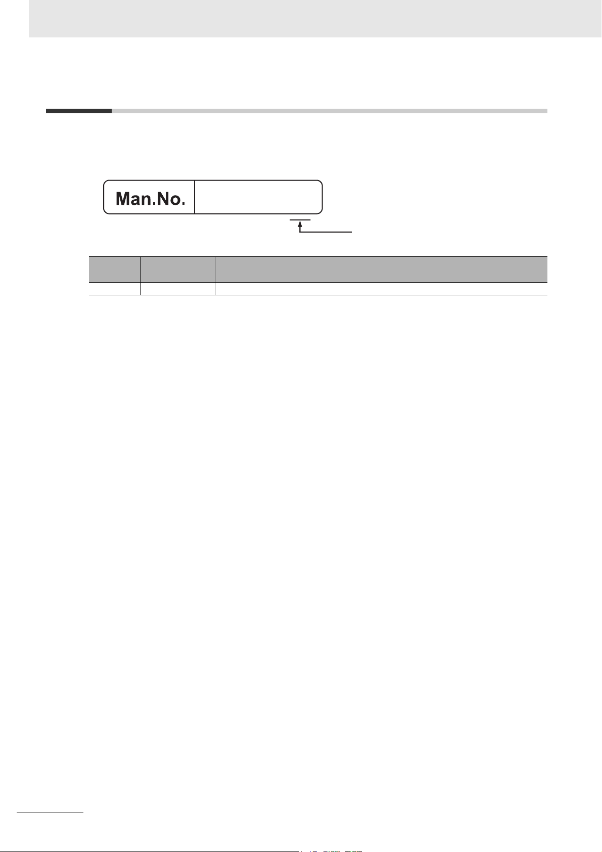
3-3 ID Information Indication Label
The ID information indication label provides information relevant to the Programmable Multi-Axis Controller.
(A)
(B)
(C)
(D)
(E)
Item Name Description
(A) Model Refer to 2-1-1 Model on page 2-2.
(B) Product name Motion Controller
(C) Power supply rat-
ing
(D) Standard logos Logos used to represent applicable standards
(E) Lot number Information on the date of manufacturing.
Details of power supply rating
The lot number of the C3KE-series Programmable Multi-Axis Controller is specified
in the form of DDMYY,where “DD” is the day, “M” is the month, and “YY” is the
year the product is manufactured. “” is a character used by OMRON. For “M”,
digits “1” to “9” respectively represent January to September, “X” represents October, “Y” November, and “Z” December.
3 - 4
CK3E-series Programmable Multi-Axis Controller Hardware User’s Manual (I610)
Page 43

Mounting and Wiring
This section describes the procedures for mounting the Programmable Multi-Axis Controller, wiring the power supply used for the Programmable Multi-Axis Controller, and
wiring the Programmable Multi-Axis Controller.
4-1 Mounting the Programmable Multi-Axis Controller . . . . . . . . . . . . . . . . . . 4-2
4-1-1 Mounting the Programmable Multi-Axis Controller . . . . . . . . . . . . . . . . . . . . . 4-2
4-1-2 Mounting Direction in Control Panels . . . . . . . . . . . . . . . . . . . . . . . . . . . . . . . 4-3
4-1-3 Mounting Method in Control Panels . . . . . . . . . . . . . . . . . . . . . . . . . . . . . . . . 4-3
4-2 Power Supply Wiring . . . . . . . . . . . . . . . . . . . . . . . . . . . . . . . . . . . . . . . . . . . 4-4
4-2-1 Power Supply Connector Specifications . . . . . . . . . . . . . . . . . . . . . . . . . . . . . 4-4
4-2-2 Wiring the Power Supply Connector . . . . . . . . . . . . . . . . . . . . . . . . . . . . . . . . 4-4
4-3 Laying the EtherCAT Network . . . . . . . . . . . . . . . . . . . . . . . . . . . . . . . . . . . . 4-7
4-3-1 Supported Network Topologies . . . . . . . . . . . . . . . . . . . . . . . . . . . . . . . . . . . . 4-7
4-3-2 Installation Precautions . . . . . . . . . . . . . . . . . . . . . . . . . . . . . . . . . . . . . . . . . 4-8
4-3-3 Installing EtherCAT Communications Cables . . . . . . . . . . . . . . . . . . . . . . . . . 4-9
4-4 Laying the Ethernet Network . . . . . . . . . . . . . . . . . . . . . . . . . . . . . . . . . . . 4-12
4-4-1 Installation Precautions . . . . . . . . . . . . . . . . . . . . . . . . . . . . . . . . . . . . . . . . 4-12
4-4-2 Installing Ethernet Networks . . . . . . . . . . . . . . . . . . . . . . . . . . . . . . . . . . . . . 4-13
4-5 USB Memory Device Connection . . . . . . . . . . . . . . . . . . . . . . . . . . . . . . . . 4-16
4
4
4-6 Grounding . . . . . . . . . . . . . . . . . . . . . . . . . . . . . . . . . . . . . . . . . . . . . . . . . . . 4-17
4-6-1 Considerations for Earthing Methods . . . . . . . . . . . . . . . . . . . . . . . . . . . . . . 4-17
4-6-2 Earthing Methods . . . . . . . . . . . . . . . . . . . . . . . . . . . . . . . . . . . . . . . . . . . . . 4-18
CK3E-series Programmable Multi-Axis Controller Hardware User’s Manual (I610)
4 - 1
Page 44
4 Mounting and Wiring
4-1 Mounting the Programmable
Multi-Axis Controller
4-1-1 Mounting the Programmable Multi-Axis Controller
z Installation in Cabinets or Control Panels
When installing the Programmable Multi-Axis Controller in a cabinet or control panel, consider the
ambient temperature, accessibility for operation and maintenance, noise immunity, as well as the
mounting direction.
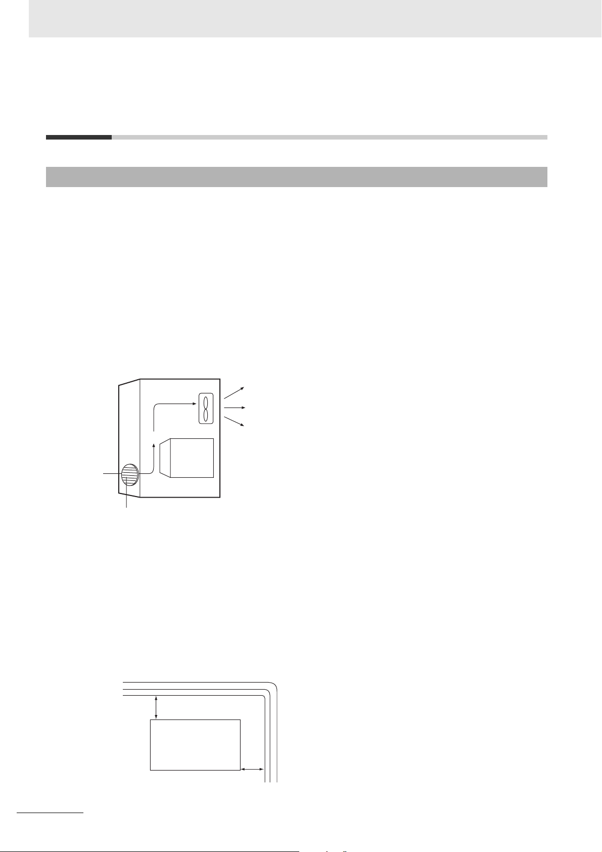
z Temperature Control
The allowable ambient operating temperature range of the Programmable Multi-Axis Controller is 0
to 45°C. When necessary, take the following steps to maintain the appropriate temperature.
• Provide sufficient space for adequate air flow.
• Do not install the Controller directly above equipment that generates a large amount of heat such
as heaters, transformers, or high-capacity resistors.
• If the ambient temperature exceeds 45°C, install a cooling fan or air conditioner.
Control
panel
Louver
Fan
CK3E-series
Programmable
Multi-Axis
Controller
z Accessibility for Operation and Maintenance
• To ensure safe access for operation and maintenance, move the Controller as far away as possible from high-voltage equipment and electrical machinery.
• It will be easy to operate the Controller if it is mounted at a height of 1,000 to 1,600 mm above the
floor.
z Improving Noise Resistance
• Do not mount the Controller in a control panel containing high-voltage equipment.
• Install the Controller at least 200 mm away from power lines.
Power lines
4 - 2
200 mm min.
CK3E-series
Programmable
Multi-Axis Controller
200 mm min.
• Ground the mounting plate between the Controller and the mounting surface.
CK3E-series Programmable Multi-Axis Controller Hardware User’s Manual (I610)
Page 45

4 Mounting and Wiring
4-1-2 Mounting Direction in Control Panels
The Programmable Multi-Axis Controller can be installed facing the front or sideways.
The Controller must be mounted in an upright position to provide appropriate cooling.
Front mounting Sideways mounting
4-1 Mounting the Programmable Multi-Axis Controller
4
4-1-2 Mounting Direction in Control Panels
4-1-3 Mounting Method in Control Panels
The following shows the mounting method of the Programmable Multi-Axis Controller. It is recommended that M4 screws be used for mounting.
1 Create holes for the screws used to mount the Programmable Multi-Axis Controller.
The screw positions are as follows.
Front mounting Sideways mounting
88±0.5
119±0.5
119±0.5
2 Insert the screws into the designated positions to mount the Programmable Multi-Axis Control-
ler.
3 Tighten the screws with 1.2 N-m torque to secure.
CK3E-series Programmable Multi-Axis Controller Hardware User’s Manual (I610)
4 - 3
Page 46

4 Mounting and Wiring
4-2 Power Supply Wiring
4-2-1 Power Supply Connector Specifications
The following power supply connector is used for the Programmable Multi-Axis Controller.
One power supply connector is included in the Programmable Multi-Axis Controller package.
Model Manufacturer
MVSTBW 2.5/3-ST-5,08 (1792760) Phoenix Contact
The following shows the pin assignment of the power supply connector used for the Programmable
Multi-Axis Controller.
123
Pin Description
124 VDC
20 VDC
3 Functional ground terminal
4-2-2 Wiring the Power Supply Connector
Compatible Wires
Wires that can be connected to terminal holes of the power supply connector are bar terminals attached
to twisted wires, twisted wires, and solid wires.
Select a power supply conductor by considering voltage drops and heat due to the cable length within
your installation environment. The following table provides information about the conductors that are
compatible with this connector.
Wire type
Solid wire
Twist ed wire
Twisted wire with bar terminal, without plastic sleeve
Twisted wire with bar terminal, with plastic sleeve
Conductor cross-sec-
tional area
0.2 to 2.5 mm
0.2 to 2.5 mm
0.25 to 2.5 mm
0.25 to 2.5 mm
2
2
2
2
Conductor length
(stripping length)
7 mm
7 mm
7 mm
7 mm
4 - 4
CK3E-series Programmable Multi-Axis Controller Hardware User’s Manual (I610)
Page 47

4 Mounting and Wiring
Grounding
The type of ground terminal on the Programmable Multi-Axis Controller is a functional ground terminal.
A functional ground terminal takes protective measures for device and system functions, including prevention of noises from external sources, and prevention of noises from devices or equipment that may
have harmful effects on other devices or equipment.
• Ground to 100 Ω or less, and as possible use a separate ground from those of other devices.
• If using an independent ground is not possible, then use a common ground. Connect to the ground
pole of the other device.
• Never use a common ground particularly with a motor, inverter, or other type of high-power equipment. Use an independent ground so that they do not affect each other.
• To reduce the risk of receiving an electric shock, do not connect devices to ground poles to which
multiple devices are connected.
• Use a ground pole as close to the Programmable Multi-Axis Controller as possible and keep the
ground line as short as possible.
4-2 Power Supply Wiring
Tools Used
Use a flat-head screwdriver to connect and remove wires.
The recommended screwdriver is as follows.
Model Manufacturer
SZF 0-0,4X2,5 Phoenix Contact
4
4-2-2 Wiring the Power Supply Connector
Procedure for Wiring the Power Supply Connector
The following shows the procedure for wiring the power supply connector.
1 Peel off the sheath from the power supply cable.
The stripping length is 7 mm if a bar terminal is not used.
If a bar terminal is used, the stripping length must be determined according to the specification
of the bar terminal.
7 mm
2 Loosen the screws securing wires on the top of the power supply connector to release the wire
insertion ports.
Screws securing wires
Wire insertion ports
CK3E-series Programmable Multi-Axis Controller Hardware User’s Manual (I610)
4 - 5
Page 48

4 Mounting and Wiring
3 Insert the wires and tighten the screws.
Tighten the screws with 0.5 to 0.6 N-m torque.
Do not apply force to the cable after connecting the wires.
4 - 6
CK3E-series Programmable Multi-Axis Controller Hardware User’s Manual (I610)
Page 49
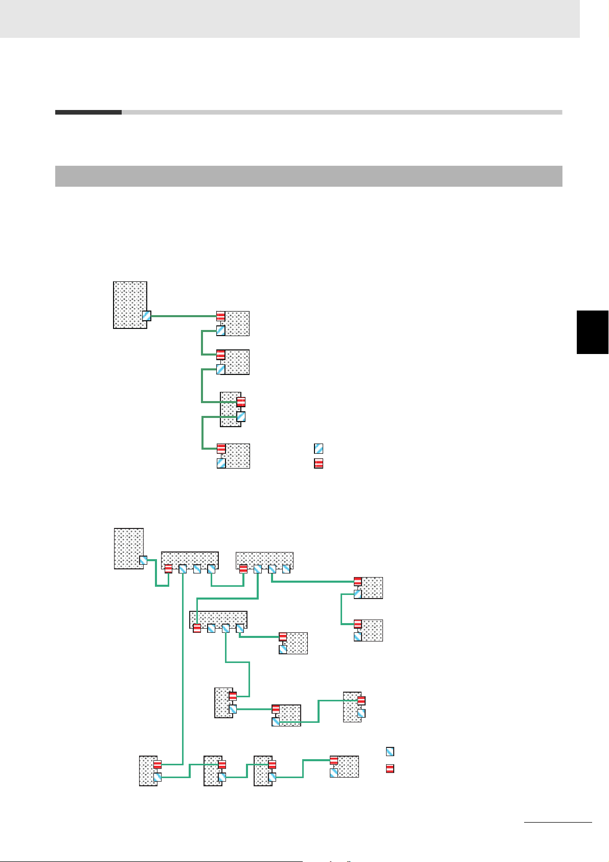
4 Mounting and Wiring
4-3 Laying the EtherCAT Network
This section describes how to install EtherCAT networks.
4-3-1 Supported Network Topologies
The Programmable Multi-Axis Controller can be connected using daisy chain connections with no
branching, or with branching connections using Junction Slaves. Examples of topology without branching and with branching (Junction Slaves) are shown below.
z No Branching
EtherCAT Master
Remote I/O Slave
Remote I/O Slave
Servo Drive Slave
Remote I/O Slave
4-3 Laying the EtherCAT Network
4
4-3-1 Supported Network Topologies
Output port
Input port
z Branching
EtherCAT Master
Junction Slave Junction Slave
Servo Drive
Slave
Junction Slave
Servo Drive
Slave
Servo Drive
Slave
Remote I/O
Slave
Remote I/O
Slave
Servo Drive
Slave
Remote I/O Slave
Remote I/O Slave
Servo Drive Slave
Remote I/O
Slave
Output port
Input port
CK3E-series Programmable Multi-Axis Controller Hardware User’s Manual (I610)
4 - 7
Page 50

4 Mounting and Wiring
4-3-2 Installation Precautions
Basic precautions for the installation of EtherCAT networks are provided below.
Precautions when Installing a Network
• When you install an EtherCAT network, take sufficient safety precautions and follow the standards
and specifications. (Refer to JIS X5252 or to electrical facility technical references.)
An expert well versed in safety measures and the standards and specifications should be asked to
perform the installation.
• Do not install EtherCAT network equipment near sources of noise. If the network must be installed in
an area with noise, take steps to address the noise, such as placing equipment in metal cases.
Precautions when Installing Communications Cables
• Check the following items on the communications cables that are used in the network.
a) Are there any breaks?
b) Are there any shorts?
c) Are there any connector problems?
• When you connect the cable to the communications connectors on devices, firmly insert the communications cable connector until it locks in place.
• Do not lay the communications cables together with high-voltage lines.
• Do not lay the communications cable near devices that generate noise.
• Do not lay the communications cables in locations subject to high temperatures or high humidity.
• Do not lay the communications cables in locations subject to excessive dirt and dust or to oil mist or
other contaminants.
• There are limitations on the bending radius of communications cables. Check the specifications of
the communications cable for the bending radius.
4 - 8
CK3E-series Programmable Multi-Axis Controller Hardware User’s Manual (I610)
Page 51

4-3-3 Installing EtherCAT Communications Cables
Ethernet communications cables and connectors are used to connect the EtherCAT port of Programmable Multi-Axis Controller with EtherCAT slaves.
Use a straight, shielded twisted-pair cable (double shielding with aluminum tape and braiding) of Ethernet category 5 (100BASE-TX) or higher. Following products are recommended.
Cable with Connectors
z Sizes and Conductor Pairs: AWG 27 × 4 Pairs
4 Mounting and Wiring
4-3 Laying the EtherCAT Network
Product name Manufacturer
Cable with Connectors on
Both Ends (RJ45/RJ45)
Standard RJ45 plugs type
*1. For the latest list of the Cables, refer to the Industrial Ethernet Connectors Catalog (Cat. No. G019).
*2. The Cables are single-shielded, but the communication and noise characteristics are ensured to satisfy the
standard values.
OMRON
Corporation
Cable length [m]
0.3 XS6W-6LSZH8SS30
0.5 XS6W-6LSZH8SS50
1 XS6W-6LSZH8SS100
10 XS6W-6LSZH8SS100
*1
CM-Y
CM-Y
CM-Y
0CM-Y
Model Contact information
OMRON Customer
*2
*2
*2
*2
Service Center
z Sizes and Conductor Pairs: AWG 22 × 2 Pairs
Product name Manufacturer
Cable with Connectors on
Both Ends (RJ45/RJ45)
Rugged RJ45 plugs type
Cable with Connectors on
Both Ends (M12/M12)
Shield Strengthening
Connector cable
M12/Smartclick Connectors
Cable with Connectors on
Both Ends (M12 /RJ45)
Shield Strengthening
Connector cable
M12/Smartclick Connectors
Rugged RJ45 plugs type
OMRON
Corporation
OMRON
Corporation
OMRON
Corporation
Cable length [m]
0.3 XS5W-T421-AMD-K OMRON Customer
0.5 XS5W-T421-BMD-K
1 XS5W-T421-CMD-K
2 XS5W-T421-DMD-K
5 XS5W-T421-GMD-K
10 XS5W-T421-JMD-K
0.5 XS5W-T421-BM2-SS
1 XS5W-T421-CM2-SS
2 XS5W-T421-DM2-SS
3 XS5W-T421-EM2-SS
5 XS5W-T421-GM2-SS
10 XS5W-T421-JM2-SS
0.5
1
2
3
5
10
*1
XS5W-T421-BMC-SS
XS5W-T421-CMC-SS
XS5W-T421-DMC-SS
XS5W-T421-EMC-SS
XS5W-T421-GMC-SS
XS5W-T421-JMC-SS
Model Contact information
Service Center
4
4-3-3 Installing EtherCAT Communications Cables
*1. For the latest list of the Cables, refer to the Industrial Ethernet Connectors Catalog (Cat. No. G019).
CK3E-series Programmable Multi-Axis Controller Hardware User’s Manual (I610)
4 - 9
Page 52

4 Mounting and Wiring
Cables and Connectors
z Sizes and Conductor Pairs: AWG 24 × 4 Pairs
Part name Manufacturer Model Contact information
Cables Hitachi Metals, Ltd. NETSTAR-C5E SAB
RJ45 Connectors Panduit Corporation
*1. We recommend that you use combinations of the above Cables and Connectors.
Kuramo Electric Co., Ltd.
SWCC Showa Cable
Systems Co., Ltd.
JMACS Japan Co., Ltd.
0.5 × 4P
KETH-SB
FAE-5004
IETP-SB
MPS588
Planning Department,
*1
*1
*1
Kanetsu Co., Ltd.
Kuramo Electric Co., Ltd.
SWCC Showa Cable
Systems Co., Ltd.
*1
*1
JMACS Japan Co., Ltd.
Panduit Corporation US
Headquarters
z Sizes and Conductor Pairs: AWG 22 × 2 Pairs
Part name Manufacturer Model Contact information
Cables Kuramo Electric Co., Ltd.
SWCC Showa Cable
KETH-PSB-OMR
FAE-5002
Systems Co., Ltd.
*1
RJ45 Assembly Connec-
JMACS Japan Co., Ltd.
OMRON Corporation
PNET/B
XS6G-T421-1
tors
*1. We recommend that you use combinations of the above Cables and Connectors.
*1
*1
*1
Kuramo Electric Co., Ltd.
SWCC Showa Cable
Systems Co., Ltd.
JMACS Japan Co., Ltd.
OMRON Customer Service Center
4 - 10
CK3E-series Programmable Multi-Axis Controller Hardware User’s Manual (I610)
Page 53

4 Mounting and Wiring
Attaching the Connectors to the Cable and Pin Assignments
Use straight wiring to attach the connectors to the communications cable.
Pin No. Wire color
1 White-Green
2Green
3 White-Orange
4Blue
5White-Blue
6Orange
7 White-Brown
8Brown
Hood Shield
*1. Connect the cable shield to the connector hood at both ends of the cable.
*2. There are two connection methods for Ethernet: T568A and T568B. The T568A connection method is shown
above, but the T568B connection method can also be used.
Wire color Pin No.
White-Green 1
Green 2
White-Orange 3
Blue 4
White-Blue 5
Orange 6
White-Brown 7
Brown 8
Shield Hood
z Connector Specifications
Item Specification
Electrical characteristics Conforms to IEEE 802.3 standards.
Connector structure RJ45 8-pin modular connector (Conforms to ISO 8877.)
z Pin Assignments
4-3 Laying the EtherCAT Network
4
4-3-3 Installing EtherCAT Communications Cables
Pin No. Signal name Abbreviation Signal direction
1 Transmission data + TD+ Output
2 Transmission data − TD− Output
3 Reception data + RD+ Input
8
1
4 Not used. --- ---
5 Not used. --- ---
6 Reception data − RD− Input
7 Not used. --- ---
8 Not used. --- ---
Hood Frame ground FG ---
CK3E-series Programmable Multi-Axis Controller Hardware User’s Manual (I610)
4 - 11
Page 54

4 Mounting and Wiring
4-4 Laying the Ethernet Network
4-4-1 Installation Precautions
Basic precautions for the installation of Ethernet networks are provided below.
Precautions when Installing a Network
• When you install an Ethernet network, take sufficient safety precautions and follow the standards and
specifications. (Refer to JIS X5252 or to electrical facility technical references.)
An expert who is well trained in safety measures, standards and specifications should be asked to
perform the installation.
• Do not install Ethernet network equipment near sources of noise.
If the network must be installed in an area subject to noise, take steps to address the noise, such as
placing equipment in metal cases.
Precautions when Installing Communications Cables
• Check the following items on the communications cables that are used in the network.
a) Are there any breaks?
b) Are there any shorts?
c) Are there any connector problems?
• When you connect the cable to the communications connectors on devices, firmly insert the communications cable connector until it locks into place.
• Do not lay the communications cables together with high-voltage lines.
• Do not lay the communications cable near devices that generate noise.
• Do not lay the communications cables in locations subject to high temperatures or high humidity.
• Do not lay the communications cables in locations subject to excessive dirt and dust or to oil mist or
other contaminants.
• There are limitations on the bending radius of communications cables. Check the specifications of
the communications cable for the bending radius.
4 - 12
CK3E-series Programmable Multi-Axis Controller Hardware User’s Manual (I610)
Page 55

4-4-2 Installing Ethernet Networks
The following products are recommended as devices to be used to configure an Ethernet network.
4 Mounting and Wiring
Ethernet Switches
Manufacturer Model Function
OMRON Corporation
Model W4S1-03B Priority control (QoS): Control data of EtherNet/IP is prioritized.
Model W4S1-05B
Model W4S1-05C
Failure detection: Broadcast storm, LSI error detection,
10/100BASE-TX, Auto negotiation
Number of ports
(Model W4S1-03B:3, Model W4S1-05B:5, Model W4S1-05C:5)
Cisco Systems Inc. Contact the manufacturer.
CONTEC Co., Ltd. Contact the manufacturer.
Phoenix Contact Contact the manufacturer.
4-4 Laying the Ethernet Network
4
Twisted-pair Cables, Connectors
4-4-2 Installing Ethernet Networks
z Sizes and Conductor Pairs: AWG 24 × 4 Pairs (for 1000BASE-T/100BASE-TX)
Part name Manufacturer Model Contact
Cables Hitachi Metals, Ltd. NETSTAR-C5ESAB 0.5 ×
*1
4P
Kuramo Electric Co., Ltd.
SWCC Showa Cable Systems
KETH-SB
FAE-5004
*1
*1
Co., Ltd.
RJ45 Connectors Panduit Corporation
MPS588
*1
*1. We recommend that you use combinations of the above-mentioned Cables and Connectors.
Planning Department, Kanetsu
Co., Ltd.
Kuramo Electric Co., Ltd.
SWCC Showa Cable Systems
Co., Ltd.
Panduit Corporation
Osaka office, Japan branch
z Sizes and Conductor Pairs: AWG 22 × 2 Pairs (for 100BASE-TX)
Part name Manufacturer Model Contact
Cables Kuramo Electric Co., Ltd.
SWCC Showa Cable Systems
Co., Ltd.
JMACS Japan Co., Ltd.
RJ45 Assembly
OMRON Corporation
Connectors
*1. We recommend that you use combinations of the above-mentioned Cables and Connectors.
CK3E-series Programmable Multi-Axis Controller Hardware User’s Manual (I610)
KETH-PSB-OMR
FAE-5002
PNET/B
*1
*1
Model XS6G-T421-1
*1
Kuramo Electric Co., Ltd.
SWCC Showa Cable Systems
Co., Ltd.
JMACS Japan Co., Ltd.
*1
OMRON Customer Service
Center
4 - 13
Page 56

4 Mounting and Wiring
z Size and conductor pairs: 0.5 mm × 4 Pairs (for 100BASE-TX)
Part name Manufacturer Model Contact
Cables Fujikura Ltd. F-LINK-E 0.5 mm × 4
RJ45 Connectors Panduit Corporation MPS588 Panduit Corporation
Attaching the Connectors to the Cable and Pin Assignments
Use straight wiring to attach the connectors to the communications cable.
Pairs
Planning Department, Kanetsu
Co., Ltd.
Osaka office, Japan branch
Pin No. Wire color
1 White-Green
2Green
3 White-Orange
4Blue
5White-Blue
6Orange
7 White-Brown
8Brown
Hood Shield
*1. Connect the cable shield to the connector hood at both ends of the cable.
*2. There are two connection methods for Ethernet: T568A and T568B. The T568A connection method is shown
above, but the T568B connection method can also be used.
Wire color Pin No.
White-Green 1
Green 2
White-Orange 3
Blue 4
White-Blue 5
Orange 6
White-Brown 7
Brown 8
Shield Hood
z Connector Specifications
Item Specification
Electrical characteristics Conforms to IEEE 802.3 standards.
Connector structure RJ45 8-pin modular connector (Conforms to ISO 8877.)
z Pin Assignments
4 - 14
Physical layer standards: 100BASE-TX
Pin No. Signal name
1 Transmission data + TD+ Output
2 Transmission data − TD- Output
8
1
3 Reception data + RD+ Input
4 Not used. --- --5 Not used. --- --6 Reception data − RD- Input
7 Not used. --- --8 Not used. --- ---
CK3E-series Programmable Multi-Axis Controller Hardware User’s Manual (I610)
Abbrevia-
tion
Signal direc-
tion
Page 57

Physical layer standards: 1000BASE-T
4 Mounting and Wiring
Pin No. Signal name
1 Communication data DA+ BI_DA+ Input/output
2 Communication data DA- BI_DA- Input/output
8
1
3 Communication data DB+ BI_DB+ Input/output
4 Communication data DC+ BI_DC+ Input/output
5 Communication data DC- BI_DC- Input/output
6 Communication data DB- BI_DB- Input/output
7 Communication data DD+ BI_DD+ Input/output
8 Communication data DD- BI_DD- Input/output
Abbrevia-
tion
Signal direc-
tion
4-4 Laying the Ethernet Network
Recommended Clamp Core and Attachment Procedure
An Ethernet communications error may occur even when the recommended cable and RJ45 connector
are used. In that case, attach a clamp core to the Ethernet communications cable.
The following shows the recommended clamp core and the procedure to attach it. The EU Directive
(EN 61326) ensures the compliance of the recommended clamp core in the state where it is attached
using the recommended procedure.
z Recommended Clamp Core Model
Manufacturer Product name Model
NEC TOKIN Clamp core ESD-SR-160
4
4-4-2 Installing Ethernet Networks
z Dimensions of the Recommended Product
20.0
~φ9
20.2 39.0
z Recommended Attachment Procedure
(a) Attaching the clamp core to the cable
Make one loop with the Ethernet communications cable as shown in the figure below.
(b) Attachment position
Secure the clamp core to the Ethernet communications cable close to the Ethernet communications
connector as shown in the figure below.
CK3E-series Programmable Multi-Axis Controller Hardware User’s Manual (I610)
4 - 15
Page 58

4 Mounting and Wiring
4-5 USB Memory Device Connection
Connect a USB memory device to the USB host port (Type A) on the Programmable Multi-Axis Controller to upload and download data as well as to save relevant data.
Refer to 2-2-1 USB Memory Device on page 2-5 for information on the recommended USB memory
devices.
4 - 16
CK3E-series Programmable Multi-Axis Controller Hardware User’s Manual (I610)
Page 59

4-6 Grounding
This section describes the earthing methods and precautions.
4-6-1 Considerations for Earthing Methods
Local potential fluctuations due to lightning or noise occurred by power devices will cause potential fluctuations between ground terminals of devices. This potential fluctuation may result in device malfunction or damage.To prevent this, it is necessary to suppress the occurrence of a difference in electrical
potential between ground terminals of devices. You need to consider the earthing methods to achieve
this objective.
4 Mounting and Wiring
4-6 Grounding
Earthing methods
Specification of communications cables
for EtherCAT and EtherNet
The cable shield connected to the connector
hood at both ends of the communications
cable
Equipoten-
tial bonding
system
Recommended
Star earthing
Connecting
devices and
noise sources
to separate
earth elec-
trodes
Recommended Not recom-
Connecting
devices and
noise sources
to a common
earth electrode
mended
Daisy chain
Not recommended
4
4-6-1 Considerations for Earthing Methods
Additional Information
• In a country or region where the earthing method is regulated, you must comply with the regulations. Refer to the applicable local and national ordinances of the place where you install
the system, or other international laws and regulations.
• When using Ethernet switches, ask the Ethernet switch manufacturer for information on the
environmental resistance of the Ethernet switch to use, the grounding between Ethernet
switches, or the specifications of cables.
The recommended earthing methods are given in the following table.
CK3E-series Programmable Multi-Axis Controller Hardware User’s Manual (I610)
4 - 17
Page 60

4 Mounting and Wiring
4-6-2 Earthing Methods
Each of these earthing methods is given below.
Equipotential Bonding System
Equipotential bonding is an earthing method in which steel frames and building structures, metal ducts
and pipes, and metal structures in floors are connected together and make connections to the earth
trunk line to achieve a uniform potential everywhere across the entire building. We recommend this
earthing method.
The following figure shows an example of an equipotential bonding system.
Connect the main earthing terminal and building structures together with equipotential bonding conductors and embed the mesh ground line in each floor.
Connect the ground line of each control panel to the equipotential bonding system.
Earth trunk line
Equipotential bonding conductor
Building structure
Power device
Information device
Control panel Control panelControl panel
Hub
Metal duct and pipe
Noise source
Metal structure in floor
Main earthing terminal
Earth electrode
4 - 18
CK3E-series Programmable Multi-Axis Controller Hardware User’s Manual (I610)
Page 61

4 Mounting and Wiring
Star Earthing
If the earthing method used for the building is not equipotential bonding or the earthing system is
unknown, choose (a) from among the earthing methods given below.
(a) Connecting devices and noise sources to separate earth electrodes
This is an earthing method to separately ground an earth electrode of the device that is connected
with a communications cable or other devices and an earth electrode of a high-power device that
could be a noise source, such as a motor or inverter.
Each earth electrode must be grounded to 100 Ω or less.
Connect the ground lines of the device that is connected with a communications cable and other
devices as a bundle to a single earth electrode. Be sure that the earth electrode is separated by a
minimum of 10 m from any other earth electrode of a device that could be a noise source.
4-6 Grounding
A device that could be
a noise source
PLC
Control panel
Other device
CK3E-series Programmable
Multi-Axis Controller
Hub
10 m min.
(b) Connecting devices and noise sources to a common earth electrode
This is an earthing method to connect the device that is connected with a communications cable,
other devices, and a device that could be a noise source, to a common earth electrode.
This earthing method is not recommended because the device that could be a noise source may
interfere electromagnetically with other devices.
A device that could be
a noise source
Control panel
Other device
CK3E-series Programmable
Multi-Axis Controller
4
4-6-2 Earthing Methods
Hub
CK3E-series Programmable Multi-Axis Controller Hardware User’s Manual (I610)
PLC
4 - 19
Page 62

4 Mounting and Wiring
Daisy Chain
This is an earthing method to connect the device that is connected with a communications cable, other
devices, and a device that could be a noise source using a daisy-chain topology to a common earth
electrode.
This earthing method is not recommended because the device that could be a noise source may interfere electromagnetically with other devices.
Control panel
Other device
CK3E-series Programmable
Multi-Axis Controller
Hub
A device that could be
a noise source
PLC
4 - 20
CK3E-series Programmable Multi-Axis Controller Hardware User’s Manual (I610)
Page 63

Error Processing
This section describes the procedures for checking errors that may occur during operation of the Programmable Multi-Axis Controller and taking corrective actions for the
errors.
5
5-1 Classification of Errors . . . . . . . . . . . . . . . . . . . . . . . . . . . . . . . . . . . . . . . . . 5-2
5-2 Using the Indicators to Check Errors . . . . . . . . . . . . . . . . . . . . . . . . . . . . . . 5-3
5-2-1 Indicator Types . . . . . . . . . . . . . . . . . . . . . . . . . . . . . . . . . . . . . . . . . . . . . . . . 5-3
5-2-2 Procedure for Determining Errors . . . . . . . . . . . . . . . . . . . . . . . . . . . . . . . . . . 5-4
5-3 Corrective Actions for Errors . . . . . . . . . . . . . . . . . . . . . . . . . . . . . . . . . . . . 5-5
5-3-1 Fatal Errors in the Programmable Multi-Axis Controller . . . . . . . . . . . . . . . . . 5-5
5-3-2 Non-fatal Errors in the Programmable Multi-Axis Controller . . . . . . . . . . . . . . 5-6
5
CK3E-series Programmable Multi-Axis Controller Hardware User’s Manual (I610)
5 - 1
Page 64

5 Error Processing
5-1 Classification of Errors
The errors in the Programmable Multi-Axis Controller are classified into the following two major categories.
z Fatal errors in the Programmable Multi-Axis Controller
Errors that occurred as the result of the Programmable Multi-Axis Controller being disabled.
z Non-fatal errors in the Programmable Multi-Axis Controller
Errors that can be detected and managed by the Programmable Multi-Axis Controller itself that is
still operating.
5 - 2
CK3E-series Programmable Multi-Axis Controller Hardware User’s Manual (I610)
Page 65

5 Error Processing
5-2 Using the Indicators to Check Errors
5-2-1 Indicator Types
The following shows the indicators on the Programmable Multi-Axis Controller and their functions.
5-2 Using the Indicators to Check Errors
Indicator Function
ECAT LINK Shows the link status of EtherCAT communications.
ECAT ACT Shows the data communications status of EtherCAT communications.
Ethernet LINK Shows the link status of Ethernet communications.
Ethernet ACT Shows the data communications status of Ethernet communications.
PWR/ERR Shows the power supply status to the Unit and the error status.
RDY Shows whether the Unit is in operation-ready status.
5
5-2-1 Indicator Types
CK3E-series Programmable Multi-Axis Controller Hardware User’s Manual (I610)
5 - 3
Page 66

5 Error Processing
5-2-2 Procedure for Determining Errors
When an error occurs in the Programmable Multi-Axis Controller, use the following flowchart to check
the indicators and determine whether the error is “fatal” or “non-fatal”.
Error occurs.
Fatal errors in the Programmable
Multi-Axis Controller
Lit in red.
Lit in green.
PWR/ERR
indicator (green/red)
RDY indicator
(green)
Lit.
ECAT LINK
Indicator (orange)
Lit.
Ethernet LINK
Indicator (orange)
Lit.
Not lit.
Not lit.
Not lit.
Not lit.
Power supply error
Watchdog timer error
Initial process error
Non-fatal errors in the Programmable Multi-Axis Controller
The EtherCAT physical layer link is
not established.
The Ethernet physical layer link is
not established.
The details of the error cannot be
determined solely by checking the indicators.
If communications between Power
PMAC IDE and Programmable
Multi-Axis Controller are not available,
refer to “Interrupted communications
between Power PMAC IDE and Programmable Multi-Axis Controller” in
5-3-2 Non-fatal Errors in the Programmable Multi-Axis Controller on page
5-6.
If the error state persists even after
communications are established, or if
errors other than the ones mentioned
above persist, use PMAC Power IDE
to check details. Refer to “Power
PMAC IDE User Manual” for details.
5 - 4
CK3E-series Programmable Multi-Axis Controller Hardware User’s Manual (I610)
Page 67

5 Error Processing
5-3 Corrective Actions for Errors
5-3-1 Fatal Errors in the Programmable Multi-Axis Controller
For fatal errors in the Programmable Multi-Axis Controller, take the following corrective actions depending on the nature of the error.
Details Cause Corrective action
Power supply error The unit’s input power is not supplied. Check the following items and adequately sup-
ply adequate power to the unit.
• Is the power turned on?
• Is the power cable wired correctly?
• Is the power cable free of damage?
The unit’s input power voltage is outside
the permissible range.
The power supply unit of the Programmable Multi-Axis Controller failed.
Watchdog timer
error
Initial process error Intrusion of noise Check the FG, power supply lines, communi-
Intrusion of noise Check the FG, power supply lines, communi-
Software watchdog trip caused by the
insufficient task processing time or failed
task interruption.
A momentary power interruption occurred
in the Programmable Multi-Axis Controller
during operation caused by a momentary
power interruption of the unit’s power supply.
The Programmable Multi-Axis Controller
failed.
The Programmable Multi-Axis Controller
failed.
Check the following items and adjust the voltage so that it falls within the permissible range.
• Is the power voltage within the specification
range?
• Is the power capacity sufficient?
• Is the power supply failing?
If the error still persists even after the above
corrective actions have been taken, replace
the Programmable Multi-Axis Controller.
cations lines, and other noise entry paths, and
implement noise-related countermeasures as
required.
For details, refer to the following manuals.
• Power PMAC User’s Manual
• Power PMAC Software Reference Manual
Take appropriate measures to ensure that the
specified power with the rated voltage and frequency is supplied in places where the power
supply is unstable.
Replace the Programmable Multi-Axis Controller.
cations lines, and other noise entry paths, and
implement noise-related countermeasures as
required.
Replace the Programmable Multi-Axis Controller.
5-3 Corrective Actions for Errors
5
5-3-1 Fatal Errors in the Programmable Multi-Axis Controller
CK3E-series Programmable Multi-Axis Controller Hardware User’s Manual (I610)
5 - 5
Page 68

5 Error Processing
5-3-2
Non-fatal Errors in the Programmable Multi-Axis Controller
For non-fatal errors in the Programmable Multi-Axis Controller, take the following corrective actions
depending on the nature of the error.
Details Cause Corrective action
The EtherCAT
physical layer link is
not established.
The Ethernet physical layer link is not
established.
Interrupted communications between
Power PMAC IDE
and Programmable
Multi-Axis Controller
The Ethernet cable used for EtherCAT communications is broken or the specified cable
is not being used.
A connector on the Ethernet cable used for
EtherCAT communications is disconnected,
the contact is faulty, or parts are faulty.
Noise Check noise entry paths, and implement
A slave within the EtherCAT network configuration failed.
The Programmable Multi-Axis Controller
failed.
The Ethernet cable used for Ethernet communications is broken or the specified cable
is not being used.
A connector on the Ethernet cable used for
Ethernet communications is disconnected,
the contact is faulty, or parts are faulty.
Noise Check noise entry paths, and implement
A device within the Ethernet network configuration failed.
The Programmable Multi-Axis Controller
failed.
The Ethernet cable used for Ethernet communications between Power PMAC IDE and
Programmable Multi-Axis Controller is disconnected and then reconnected while
communications are being established,
which caused communications to be interrupted.
The power to the Ethernet switch between
Power PMAC IDE and Programmable
Multi-Axis Controller is turned OFF and then
ON while communications are being established, which caused communications to be
interrupted.
The power to Programmable Multi-Axis
Controller is turned OFF and then ON while
communications are being established,
which caused communications to be interrupted.
Communications are temporarily interrupted
by noise.
If the Ethernet cable is broken or if the specified
cable was not used, replace the cable.
Reconnect the connector and check to ensure it
is mated correctly.
noise-related countermeasures as required.
Replace the slave.
Replace the Programmable Multi-Axis Controller.
If the Ethernet cable is broken or if the specified
cable was not used, replace the cable.
Reconnect the connector and check to ensure it
is mated correctly.
noise-related countermeasures as required.
Replace the device.
Replace the Programmable Multi-Axis Controller.
If communications are interrupted between
Power PMAC IDE and Programmable Multi-Axis
Controller while Ethernet communications are
established between them, the communications
cannot be reestablished simply by rectifying the
problem that interrupted the communications. To
reestablish the communication, you need to
restart Power PMAC IDE or reestablish the communications by using Power PMAC IDE. Refer
to “Power PMAC IDE User Manual” for details.
Check noise entry paths, and implement
noise-related countermeasures as required.
Then reestablish communications between
Power PMAC IDE and Programmable Multi-Axis
Controller.
To reestablish the communication, you need to
restart Power PMAC IDE or reestablish the communications by using Power PMAC IDE. Refer
to “Power PMAC IDE User Manual” for details.
5 - 6
CK3E-series Programmable Multi-Axis Controller Hardware User’s Manual (I610)
Page 69

6
Inspection and Maintenance
This section describes the procedures for the cleaning, inspection, and maintenance of
the Programmable Multi-Axis Controller.
6-1 Cleaning and Maintenance . . . . . . . . . . . . . . . . . . . . . . . . . . . . . . . . . . . . . . 6-2
6-1-1 Cleaning . . . . . . . . . . . . . . . . . . . . . . . . . . . . . . . . . . . . . . . . . . . . . . . . . . . . . 6-2
6-1-2 Periodic Inspections . . . . . . . . . . . . . . . . . . . . . . . . . . . . . . . . . . . . . . . . . . . . 6-2
6-2 Maintenance Procedures . . . . . . . . . . . . . . . . . . . . . . . . . . . . . . . . . . . . . . . . 6-4
6-2-1 Unit Replacement Precautions . . . . . . . . . . . . . . . . . . . . . . . . . . . . . . . . . . . . 6-4
6-2-2 Backup . . . . . . . . . . . . . . . . . . . . . . . . . . . . . . . . . . . . . . . . . . . . . . . . . . . . . . 6-4
6-2-3 Unit Replacement . . . . . . . . . . . . . . . . . . . . . . . . . . . . . . . . . . . . . . . . . . . . . . 6-4
6
CK3E-series Programmable Multi-Axis Controller Hardware User’s Manual (I610)
6 - 1
Page 70

6 Inspection and Maintenance
6-1 Cleaning and Maintenance
6-1-1 Cleaning
Perform the following cleaning procedures periodically to ensure the Programmable Multi-Axis Controller is maintained in optimum operating condition.
• During daily cleaning, wipe off dust and dirt using a soft, dry cloth.
• If any dust or dirt remains even after wiping using a soft, dry cloth, wipe over with a cloth that has
been wet with a sufficiently diluted detergent (2%) and wrung dry.
• Smudges may remain on the Unit from gum, vinyl, or tape that was left on for a long time. Remove
the smudges when cleaning.
6-1-2 Periodic Inspections
The Programmable Multi-Axis Controller can deteriorate under adverse environmental conditions. Periodic inspections are thus required to ensure that the required conditions are being maintained.
Inspection is recommended at least once every six months to a year, but more frequent inspections will
be necessary in adverse environments.
Take immediate steps to correct the situation if any of the conditions in the following table are not met.
Periodic Inspection Items
No. Item Inspection details Criteria Correction
1 External power sup-
ply
2 Ambient environment Check the ambient tem-
Check for voltage fluctuations at the power supply terminals.
perature.
(Inside the control panel
if the Controller is in a
control panel.)
Check the ambient
humidity. (Inside the control panel if the Controller
is in a control panel.)
Check that the Controller
is not in direct sunlight.
Check for accumulation
of dirt, dust, salt, metal
powder, etc.
The voltage must be
within the allowable voltage fluctuation range.
0 to 45°C Use a thermometer to
Relative humidity must
be 10% to 95% with no
condensation.
Not in direct sunlight Protect the Controller if
No accumulation Clean and protect the Con-
Take necessary steps to
bring the voltage of the
supplied power to within
the allowable voltage fluctuation range.
check the temperature and
ensure that the ambient
temperature remains within
the allowed range of 0 to
45°C.
Use a hygrometer to check
the humidity and ensure
that the ambient relative
humidity remains between
10% and 95%. Make sure
that no condensation forms
due to rapid changes in
temperature.
necessary.
troller if necessary.
6 - 2
CK3E-series Programmable Multi-Axis Controller Hardware User’s Manual (I610)
Page 71
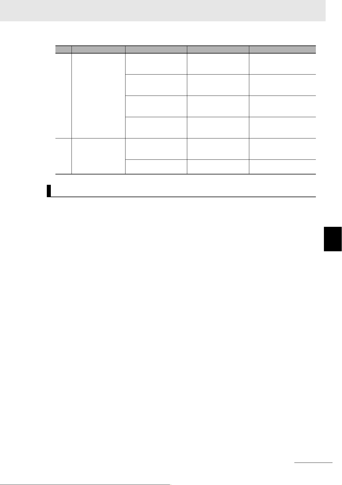
6 Inspection and Maintenance
No. Item Inspection details Criteria Correction
2 Ambient environment Check for water, oil, or
chemical sprays hitting
the Controller.
Check for corrosive or
flammable gases in the
area of the Controller.
Check the level of vibration or shock.
Check for noise sources
near the Controller.
3 Mounting and wiring
status
Check that cable connectors are fully inserted
and locked.
Check for damaged
external wiring cables.
No spray Clean and protect the Con-
troller if necessary.
No corrosive or flammable gases
Vibration resistance and
shock resistance must
be within specifications.
No significant noise
sources
No looseness Fully inserted and lock the
No visible damage Check visually and replace
Check by smell or use a
sensor.
Install cushioning or shock
absorbing equipment if
necessary.
Either separate the Controller and noise source or
protect the Controller.
connectors.
cables if necessary.
6-1 Cleaning and Maintenance
Tools Required for Inspections
z Required Tools
• Flat-head screwdriver
• Phillips screwdriver
• Voltage tester or digital voltmeter
• Industrial alcohol and clean cotton cloth
• Antistatic gas duster
z Tools Required Occasionally
• Oscilloscope
• Thermometer and hygrometer
6
6-1-2 Periodic Inspections
CK3E-series Programmable Multi-Axis Controller Hardware User’s Manual (I610)
6 - 3
Page 72

6 Inspection and Maintenance
6-2 Maintenance Procedures
This section describes the procedures for backing up the Programmable Multi-Axis Controller data and
replacing a Unit.
6-2-1 Unit Replacement Precautions
Note the following when replacing any faulty Unit.
• Do not replace a Unit until the power is turned OFF.
• Check the new Unit to ensure that there are no errors.
• If you return a faulty Unit for repair, describe the problem in as much detail as possible and enclose
this description with the Unit.
6-2-2 Backup
Back up the Programmable Multi-Axis Controller data so that the data can be restored when a failure or
other problems occur.
Use Power PMAC IDE to create a backup file. Power PMAC IDE is also used to restore the backup file
to the Programmable Multi-Axis Controller.
For details of the backup and restoration procedures, refer to “Power PMAC IDE User Manual”.
6-2-3 Unit Replacement
Procedure for Replacing the Programmable Multi-Axis Controller
The following describes the basic procedure for replacing the Programmable Multi-Axis Controller.
No. Step Description Reference
1 Creation of a backup
file
2 Deactivation of the cur-
rently connected network
3 Removal Turn OFF the power to the Programmable
4 Mounting Replace the Programmable Multi-Axis Controller
5 Connection with Power
PMAC IDE
Create a backup file for the Programmable
Multi-Axis Controller by using Power PMAC IDE.
The backup file can be saved on the computer
hard disk where Power PMAC IDE is installed or
on a USB memory device connected to the computer.
Deactivate the EtherCAT network.
If the Programmable Multi-Axis Controller has
been connected to the Ethernet network, take
appropriate measures so that disconnection of the
Controller from the network does not affect your
operations.
Multi-Axis Controller, and disconnect cables.
with a new one, connect the cables, and turn the
power ON.
Establish communications between Power PMAC
IDE and the new Programmable Multi-Axis Controller.
Refer to “Power PMAC
IDE User Manual” for
details.
Refer to “Power PMAC
IDE User Manual” for
details.
---
---
Refer to “Power PMAC
IDE User Manual” for
details.
6 - 4
CK3E-series Programmable Multi-Axis Controller Hardware User’s Manual (I610)
Page 73

6 Inspection and Maintenance
No. Step Description Reference
6 Restoration and verifi-
cation
7 Activation of the Ether-
CAT network
8 Checking operation By using Power PMAC IDE and the actual
Restore the backup file to the Programmable
Multi-Axis Controller by using Power PMAC IDE.
Then, verify the file restored to the Programmable
Multi-Axis Controller with the backup file to ensure
that the backup file has been adequately restored.
Activate the EtherCAT network by using Power
PMAC IDE and change the state of the connected
EtherCAT slaves to an operational state.
machine, check the motor settings and that the
program has been adequately restored.
Refer to “Power PMAC
IDE User Manual” for
details.
Refer to “Power PMAC
IDE User Manual” for
details.
Refer to “Power PMAC
IDE User Manual” for
details.
Procedure to Replace an EtherCAT Slave
To replace an EtherCAT slave connected to the Programmable Multi-Axis Controller, you can only disconnect the target slave and slaves connected after it from the EtherCAT network. This enables you to
replace slaves without interrupting the total communication system when performing maintenance or
replacement work in the case a slave malfunctions.
6-2 Maintenance Procedures
The following describes the basic procedure to replace a slave connected to the Programmable
Multi-Axis Controller.
No. Step Description Reference
1 State transition instruc-
tion
2 Disconnection of the
Unit to be replaced
3 Mounting of a Unit Connect a new slave to the EtherCAT network, and
4 Mounting and wiring of
the Programmable
Multi-Axis Controller
5 Confirmation of con-
nection
By using Power PMAC IDE, instruct the slave to be
replaced and slaves connected after it to change to
the init state. The init state is a state where communications cannot be carried out.
Then, ensure that the state transition of the slaves
has been completed successfully.
Turn OFF the unit power supply of the slave to be
replaced or remove the EtherCAT communications
cable to disconnect the slave from the EtherCAT
network.
turn ON the unit power supply of the slave. In
doing so, reconfigure the settings, if required, by
referring to the manual for the slave.
By using Power PMAC IDE, instruct the slave in
the init state to change to the communications status (pre-operational state, safe-operational state,
or operational state) and allow it to connect to the
EtherCAT network. Refer to “Power PMAC Software Reference Manual” for detailed instructions.
Make sure that the state transition of the slaves
has been completed successfully.
Refer to “Power PMAC
Software Reference Manual”.
---
Refer to the manual for
the EtherCAT slave.
Refer to “Power PMAC
Software Reference Manual”.
Refer to “Acontis EC-Engineer manual” and “Power
PMAC Software Reference Manual”.
6
6-2-3 Unit Replacement
CK3E-series Programmable Multi-Axis Controller Hardware User’s Manual (I610)
6 - 5
Page 74

6 Inspection and Maintenance
6 - 6
CK3E-series Programmable Multi-Axis Controller Hardware User’s Manual (I610)
Page 75

Appendices
The following provides the dimension diagram, and restrictions on using the OMRON
EtherCAT Coupler Unit.
A-1 Dimension Diagram . . . . . . . . . . . . . . . . . . . . . . . . . . . . . . . . . . . . . . . . . . . . . . . . . . . A-2
A-2 Restrictions on Using the OMRON NX-Series EtherCAT Coupler Unit . . . . . . . . . . A-3
A
A
CK3E-series Programmable Multi-Axis Controller Hardware User’s Manual (I610)
A - 1
Page 76

Appendices
A-1 Dimension Diagram
The following shows the dimension diagrams of the Programmable Multi-Axis Controller. The unit of
dimension is millimeter.
z Main Body Only
28.6
25.8
110
z With Power Connector
28.6
25.8
14.9
11.6
15.2
170.9
170.9
150.5
150.5
125
94.1
5.4
110
z Mounting Dimensions
Front mounting Sideways mounting
170.9
14.9
28.6
2-M4
PAN HEAD SCREW
119
125
4-M4
PAN HEAD SCREW
125
43.4 88
119
125
A - 2
CK3E-series Programmable Multi-Axis Controller Hardware User’s Manual (I610)
Page 77

A-2 Restrictions on Using the OMRON
NX-Series EtherCAT Coupler Unit
Appendices
When OMRON NX-series EtherCAT Coupler Units are used as slaves of the Programmable Multi-Axis
Controller as the EtherCAT master, the following models and unit versions of EtherCAT Coupler Units
can be connected.
Model Unit version Connectable/Unconnectable
Model NX-ECC203 Ver. 1.4 or later Connectable
Ver. 1.3 or earlier Unconnectable
Model NX-ECC202 All versions
Model NX-ECC201 All versions
A-2 Restrictions on Using the OMRON NX-Series EtherCAT Coupler Unit
A
CK3E-series Programmable Multi-Axis Controller Hardware User’s Manual (I610)
A - 3
Page 78

Appendices
A - 4
CK3E-series Programmable Multi-Axis Controller Hardware User’s Manual (I610)
Page 79

Index
I
I
CK3E-series Programmable Multi-Axis Controller Hardware User’s Manual (I610)
I - 1
Page 80

Index
Index
B
branching connections ................................................... 4-7
C
Compatible Wires ........................................................... 4-4
D
daisy chain connections with no branching .................... 4-7
DIAG.MODE ................................................................... 3-3
E
ECAT ACT ...................................................................... 3-3
ECAT LINK ..................................................................... 3-3
EC-Engineer ................................................................... 1-5
EtherCAT communications connector ............................ 3-2
EtherCAT communications port operation indicators ..... 3-2
EtherCAT master ............................................................ 1-2
Ethernet ACT .................................................................. 3-3
Ethernet communications connector .............................. 3-2
Ethernet communications port operation indicators ....... 3-2
Ethernet LINK ................................................................. 3-3
F
Fatal errors in the Programmable
Multi-Axis Controller .................................................... 5-2
Functional ground terminal ............................................. 4-4
G
Grounding ....................................................................... 4-5
I
Initial process error ......................................................... 5-5
N
Non-fatal errors in the Programmable
Multi-Axis Controller .................................................... 5-2
P
Power PMAC IDE ........................................................... 1-5
Power PMAC-NC16 Runtime ......................................... 1-5
Power PMAC-NC16 SDK ............................................... 1-5
Power supply connector ................................................. 3-2
Power supply error ......................................................... 5-5
Procedure for Wiring the Power Supply Connector ....... 4-5
Programmable Multi-Axis Controller .............................. 1-2
Programmable Multi-Axis Controller specific language .. 1-2
PWR/ERR ...................................................................... 3-3
R
RDY ................................................................................ 3-3
Recommended Clamp Core ......................................... 4-15
Recommended power supply ......................................... 2-5
recommended screwdriver ............................................. 4-5
recommended USB memory .......................................... 2-5
T
twisted-pair cable ........................................................... 4-9
U
Unit operation indicators ................................................ 3-2
USB 2.0 connector ......................................................... 3-2
USB 3.0 connector ......................................................... 3-2
W
Watchdog timer error ...................................................... 5-5
J
Junction Slaves .............................................................. 4-7
M
Maintenance mode enter button ..................................... 3-2
Maintenance mode LED ................................................. 3-2
Maximum number of controlled axes ............................. 2-2
MODBUS-TCP ............................................................... 1-3
I - 2
CK3E-series Programmable Multi-Axis Controller Hardware User’s Manual (I610)
Page 81

Page 82

OMRON Corporation Industrial Automation Company
Kyoto, JAPAN
Contact: www.ia.omron.com
Regional Headquarters
OMRON EUROPE B.V.
Wegalaan 67-69, 2132 JD Hoofddorp
The Netherlands
Tel: (31)2356-81-300/Fax: (31)2356-81-388
OMRON ASIA PACIFIC PTE. LTD.
No. 438A Alexandra Road # 05-05/08 (Lobby 2),
Alexandra Technopark,
Singapore 119967
Tel: (65) 6835-3011/Fax: (65) 6835-2711
OMRON ELECTRONICS LLC
2895 Greenspoint Parkway, Suite 200
Hoffman Estates, IL 60169 U.S.A.
Tel: (1) 847-843-7900/Fax: (1) 847-843-7787
OMRON (CHINA) CO., LTD.
Room 2211, Bank of China Tower,
200 Yin Cheng Zhong Road,
PuDong New Area, Shanghai, 200120, China
Tel: (86) 21-5037-2222/Fax: (86) 21-5037-2200
Authorized Distributor:
© OMRON Corporation 2016 All Rights Reserved.
In the interest of product improvement,
specifications are subject to change without notice.
Cat. No. I610-E1-01
0816
 Loading...